
E.. C.. Carter - Defense Technical Information Center · NORTH ATLANTIC TREATY ORGANIZATION ......
18
-------------------------------------', J AGARD-AR-81 E .. C .. Carter DISTRIBUTION AND AVAILABILITY ON BACK COVER- Fo:c'ce F40GOO-75-C-OOOl
-
Upload
truongdung -
Category
Documents
-
view
213 -
download
0
Transcript of E.. C.. Carter - Defense Technical Information Center · NORTH ATLANTIC TREATY ORGANIZATION ......

-------------------------------------',
J
AGARD-AR-81
E ..C..Carter
DISTRIBUTION AND AVAILABILITYON BACK COVER-
Fo:c'ce
F40GOO-75-C-OOOl

NORTH ATLANTIC TREATY ORGANIZATION
ADVISORY GROUP FOR AEROSPACE RESEARCH AND DEVELOPMENT
Introduction General Considerations
(ORGANISATION DU TRAITE DE L'ATLANTIQUE NORD)
AGARD Advisory Report No.81
TECHNICAL EVALUATION REPORT
ON FLUID DYNAMICS PANEL SYMPOSIUM ON
AIRFRAME/PROPULSION INTERFERENCE
by
E.C.Carter
Aircraft Research Association, Bedford, UK
CONTENTS
Air Intakes and Airframe/Inlet Interactions Nozzles/ Afterbodies Flow Field and Airframe Interference Wind Tunnel Testing and Correlation with Flight Data Integration Design and Accounting Procedures Conclusions and Recommendations Appendix Figures
Technical Evaluation of the Fluid Dynamics Panel Symposium held in Rome, Italy, 3-6 September 1974. The Proceedings are published as AGARD-CP-1S0.
Page 1 1 2 2 4 5 6 8
10
THE MISSION OF AGARD
The mission of AGARD is to bring together the leading personalities of the NATO nations in the fields of science and technology relating to aerospace for the following purposes:
- Exchanging of scientific and technical information;
- ContiilUously stimulating advances in the aerospace sciences relevant to strengthening the common defence posture;
- Improving t~e co-operation among member nations in aerospace research and development;
- Providing scientific and technical advice and assistance to the North Atlantic Military Committee in the field of aerospace research and development;
- Rendering scientific and technical assistance, as requested, to other NATO bodies and to member nations in connection with research and development problems in the aerospace field;
- Providing assistance to member nations for the purpose of increasing their scientific and technical potential;
- Recommending effective ways for the member nations to use their research and development capabilities for the common benefit of the NATO community.
The highest authority within AGARD is the National Delegates Board consisting of officially appointed senior representatives from each member nation. The mission of AGARD is carried out through the Panels which are composed of experts appointed by the National Delegates, the Consultant and Exchange Program and the Aerospace Applications Studies Program. The results of AGARD work are reported to the member nations and the NATO Authorities through the AGARD series of pUblications of which this is one.
Participation in AGARD activities is by invitation only and is normally limited to citizens of the NATO nations.
The content of this publication has been reproduced directly from material supplied by AGARD or the author.
.'%,
Published May 1975
Copyright © AGARD 1975
533.695.27: 533.6.07
Printed by Technical Editing and Reproduction Ltd Harford House, 7-9 Charlotte St, London. W iP iHD
ii
I!
TECHNICAL EVALUATION REPORT
by
E.C.CARTER Aircraft Research Assocn.Ltd. U.K.
1. INTRODUCTION
The AGARD Fluid Dynamics Panel organised a four-day Symposium on 'Airframe Propulsion Interference' from 3rd - 6th September 1974. The meeting was held in the Palazzo Aeronautica, Rome, Italy.
The Programme Committee, which was Chaired by Mr. P.P.Antonatos of Wright Patterson AFB, comprised Dr.J.Barche (Germany), Professor C.Buongiorno (Italy), M.P.Carriere (France), Mr.R.Dietz (USA), Mr.J.P.Hartzuiker (Netherlands), Dr.R.C.Pankhurst (UK) and Mr.R.J.Templin (Canada). The members of the Committee also acted as Chairmen for the four technical sessions. The Conference ended with a round-table discus~ion before a large audience for which the Panel consisted of Mr.Antonatos (Chairman), Dr.Barche, M.Carriere, Professor Ferri (USA) and Mr.Carter (UK).
-Section 2 of this report sets the scene for the need for this Symposium and its relation to the previous Lecture Series by the Propulsion and Energetics Panel on this subject. Sections 3 to 6 inclusive deal with the content and discussions on the four sessions. Section 7 presents the author's conclusions and recommendations to the Fluid Dynamics Panel.
This report contains detailed views and comments which are the responsibility of the author and does not necessarily represent the views of the Programme Committee.
2. GENERAL CONSIDERATIONS
The subject title 'interference' provides almost unlimited scope in the analysis of any aeronautical subject. There is a particular inevitability of interference in the 'engine airframe combination' which provides a challenge to the designer and the theoretician. Naturally the ultimate objective of the outcome of such a meeting as this is the provision of theoretical methods perhaps combined with empiricisms, to enable us to design intelligently to derive the maximum benefit obtainable from shapes which are dictated by other-than-fluid-dynamic considerations.
Engines have to be 'accommodated' on the airframe at a variety of posLtLons. To an extent the early families of subsonic civil transports have tried to wrap their engines in ideal slender bodies and place them at positions where they and their associated airframes are not aware of each other. The more recent designs however have had to accept the close wing/nacelle proximity imposed by high by-pass engines and ground clearance. Future designs are considering noise shielding configurations where the permission-to-fly becomes more important than the absolute economics. The fighter design has provided an amazing range of solutions to its particular problems where, as distinct from the transport, drag is not always of prime importance. For the fighter, the interference fields can strongly influence the intake flow giving benefits or losses to the intake recovery, distortion to the engine face and limits to the operating boundaries for the aircraft. The body, wing and tail interference fields can influence the afterbody recovery and separations to an extent that makes the results of theoretical solutions and Reynolds number effects insignificant by comparison.
A specialist meeting of this type has to be planned to illustrate the theoretical approaches to the problems, the experimental validation and the relative gains to be made in the many areas of study. The meeting was divided into four sessions considering the inlet, the afterbody, testing, and integration design and accounting procedures respectively. These divisions followed closely the title lectures of the AGARD PEP Lecture Series 53 on Airframe/Engine Integration and it is of interest to see what progress has been made in the past 2 years. At that time Professor Ferri, the Lecture Series Director, laid strong emphasis on the need for theoretical methods and new approaches. It was proposed that the present strong reliance on experimental data should be coordinated with numerical methods to provide data based on the best combination of both fields. The Lecture Series did not expand in any detail on this thesis; it is of interest to see whether any progress has been made along these lines.
It might have been questioned why the Fluid Dynamics Pinel should see the need to raise the subject of engine-airframe interference as soon as 2 years after the PEP Lecture Series. The number and range of papers, the specialist authors and the distinguished audience and visitors provided the answer of the wish of many workers to be informed and to take part in the discussions on the subject. The gains and losses associated with interference can be very large particularly when one is operating on improvements to gross thrust by way of either the inlet or exhaust performance. A poor high by-pass nozzle performance can soon eliminate the benefits of an exotic supercritical wing.
In retrospect, both for the benefit of the audience and the present authors, it would have helped to set the scene with an invited introductory paper for each of the four sessions. Only Session 1 had such an introduction to intake-airframe interaction by J.Leynaert~ the other sessions tended to dive straight into their subject on some particular facet which did not necessarily set the scene. Session IV was nevertheless adequately introduced by papers by Brazier and by Richey which were sufficiently wide to serve the introductory purpose.
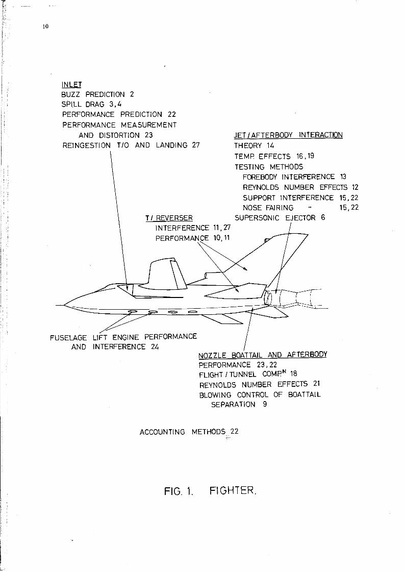
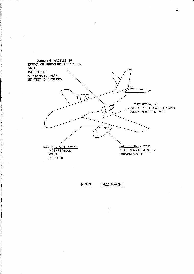
To assist the reader who may have specialist interests, Figs.l and 2 illustrate the particular areas of study treated by the numbered papers.
-

2
3. AIR INTAKES AND AIRFRAME/INLET INTERACTIONS
Somewhat surprisingly there were only 4 papers in this session although the first half of the paper by Richey23 and that of Krenz26 could well have found a place here. This is perhaps indicative of the efforts that are made to keep the inlets in a controlled environment and how this is much more in the designer's control than the nozzle region. Comprehensive measurements made by Richey23 show the effect of flight attitudes and speed on the intake approach flow. Other results2 ,3,4 obtained on models in the correct interference environment illustrate the effects on drag and inlet stability.
1 The introductory paper by Leynaert covers a wide range of inlet interaction problems including the
installation of subsonic nacelles on wings, ground effects and wing-interference on spanwise lift and induced drag. The Concorde installation is naturally discussed showing examples of wing and sideplate interference and mutual interference of the twin ducts. Leynaert also introduces theoretical methods of flow field calculation around supersonic and hypersonic bodies relating some of the results to experimental data; the references to this work should be of value to other workers in the field.
2 The paper by Hall considers the airframe interference effects associated with the distortion of the
total pressure flow field approaching the intake and the effects of this on the intake instability characteristics. A criterion is postulated that the condition where the approach total pressure in a stream tube combined with the inlet shock losses results in a total pressure which is less than the engine face static corresponds to the, buzz of that stream tube. Good agreement with experiment is shown at a Mach number of 2. This paper provides scope for further work using theoretical methods of flow-field prediction to deduce buzz boundaries.
3 4-The remaining two papers in this section ' consider the drag of two-dimensional inlets. Transonic
drag of supersonic inlets has an important place in the mission requirements of fighter aircraft and the high subsonic ,leg of the overland supersonic transport flight path. The paper by Thornley3 deals with the experimental technique of measuring the transonic spillage drag of a twin-duct inlet model. The paper deals with the detailed calibration necessary to obtain the high accuracy of definition of internal flow. To workers planning partial model measurements this paper is of value as a warning of the degree of definition needed at a momentum station to provide accurate drag. The paper by Callahan4- deals with inlet drag tests in the more general context of the whole mission; unfortunately this paper does not include any significant quantity of drag data nor an analysis of the drag accuracy. This latter would have been of interest as the method measures the drag on a part-inlet and consequently would have to deal with the difficult task of momentum definition at the engine face split line.
These three specialist papers have contributed to particular items associated with the performance of supersonic i~tegrated inlets. The interference aspects in these cases were associated with the fuselage viscous flow fields; the obvious missing link was a paper discussing current techniques - or lack of - for the calculation of the intake environment. Even if nothing new could be added, many workers would be interested in a review of current methods, their limitations and their success in relation to experimental results. References in Leynaert1 to papers by Antonatos, Babenko and Walitt deal with the supersonic problem; but subsonic and supercritical methods now being developed deserve mention. In the meeting discussions on the above papers on inlets no pleas were made for information in other areas of inlet/airframe interference so it would appear that the fundamental problems are recognised and only need theoretical and improved technique solutions.
4. NOZZLES/AFTERBODIES FLOW FIELD AND AIRFRAME INTERFERENCE
This session of the meeting covered 10 papers; they comprised a reasonable cross section of the problem areas with little overlap but the first of the papers 5 on model by-pass engine representation would have been better placed in the third session on testing techniques. Analytical papers discuss the mixing flows from a high by-pass fanS, the flow in the afterbody/jet region at transonic speed for normal 7 and very high pressure ratios l 4-. Two papers10,11 discuss thrust reversers, related particularly to the effects of forward speed onreingestion and the effects on aircraft stability. Experimental results showing the benefits of low velocity air injection on the supression of afterbody drag 9 at transonic speeds are given along with two papers on afterbody testing technique problems. The first of these by Aulehla12 gives a significant warning on the problems of part-body testing methods and on the use of tunnels for Reynolds number effects. The paper by Reid13 also spells out a warning on the use of correction methods for forebody interference, particularly for base pressures on cylindrical afterbodies.
On the whole the papers have covered interesting features, touched on many areas and reiterated how little is known about afterbody flow fields even in the simplest axi-symmetric cases. Theoretical methods are not making a lot of progress but the degree of aerodynamic interference in this area is so great that it must be doubted whether theoretical methods can ever be of any practical value other than as an indication of trends. What is perhaps disconcerting is the auspicion that can be cast on the experimental methods; without reliable experimental data analytical methods are not going to be supported and the cross feed between the two will not occur. Afterbody/nozzle test techniques have always been amongst the most difficult; many papers for many years have described' the multitude of methods used in the measu~ement and accounting of afterbody thrust and drag. Pressure distributions have mainly been used for diagnostic purposes on the more complex bodies where only force measurement can provide a satisfactory integration. Most methods of force measurement are associated with a metric (live) part-body only, usually with a metric to non-metric split line near the maximum cross section. Even in this most simple of cases it is shown that a part-body force can be seriously in error if the tunnel reference pressure is not known to a high order of accuracy. It is pointed out by Aulehla12 how part-bodies are particularly sensitive to wind tunnel static pressure errors and how it might be possible to interpret a measured force change as being associated with a model or flow parameter change when in reality it is associated with a tunnel wall interference or calibration change. It is to be hoped that most tunnel establishments are aware of these problems, although it is possible that an attitude of complacency associated with comparative testing could lead to the issue of absolute data which is not so reliable.
-

l It is very appropriate that there should at this moment be a Jo~nt FDP/PEP Working Group looking at
the whole problem of nozzle testing techniques. Their findings should be valuable and opportune.
Now dealing briefly with the individual papers, the theoretical work by Maria~Sube8 deals with the mixing of internal/external flows at an axi-symmetric nozzle exit. The two. cases of subsonic external flow with supersonic and subsonic jet respectively are considered. The external and internal flows are calculated by a finite difference or a small perturbation method in conjunction with a hodograph or characteristics method respectively for the jet. The calculations are compressible inviscid and comparison with experimental results is given for an AGARD and a NACA afterbody. The method shows reasonable comparisons but the trends with pressure ratio are not good~ the author attributes this to viscous effects although7results with two values of displacement thickness are slightly worse than the inviscid case. Quermann provides another solution to this problem, dealing with both a subsonic and supersonic jet from the base of an axi-symmetric body. The inviscid subsonic potential flow around a body with a defined jet boundary is obtained by the method of A.M.O.Smith and a Goethert compressibility correction is applied. The Korst method of supersonic base-flow analysis is adapted, by the use of elliptic base streamlines, to the subsonic case. Results of flight, wind tunnel, and calculation are presented showing varying degrees of correlation. An important feature of this method is the ability to allow for jet gas properties and temperature, base bleeds and other influencing parameters. Prediction of the interaction between jet expansion and afterbody pressures is a useful feature of this technique. The paper by Moulden and Wu14 provides a good background to the current theoretical situation. In attempting to highlight the solution of the mixed flow region on the boattail and base of the simple axi-symmetric body with completely frozen jet flow, many problems are presented. The use of large computers for exact solutions is reconnnended but difficulties as'sociated with the modelling of the turbulent boundary layer make the resultant solution for flow on viscous bodies far from 'exact'. The point is also made that detailed and fundamental experimental data should be available as a basis for the theoretical understanding. The discussion in section 5 of paper 14 is connnended to the reader requiring a brief sunnnary on the current analytical situation. As a connecting paper between the theoretical and practical, Piva9 describes experiments on the reduction of afterbody drag at transonic speeds by the use of low speed air injection to control the separation. An estimate of the cost of taking the injected air on board would have been worthy of mention as the use of low total pressure air from bleeds has often been shown to be difficult and impractical.
The two thrust reverser papers in this section deal with the effect of forward speed on reverser performance10,11 and with reingestion and aircraft handling. HardylO considers two types of Concorde 'reverser, the first comprising a reverser bucket in the ejector shroud with reverser jets passing through grills at the upstream end of the shroud, the second being a target type. reverser behind the shroud. It is shown that the performance of the two types is very similar.but the second is mechanically simpler and has better sup~rsonic performance. It is interesting to note how. the similar performance of the two reversers is obtained for different reasons. Hardy provides correlating parameters to convert static performance to forward speed performance. The paper by Wilmer11 is complementary to 10, and makes easy and interesting reading on testing techniques, reingestion speeds and aircraft handling. These two papers in conjunction with 27 on thrust-reverser optimisation provide a well documented section of the meeting. The work is specialised and the interference discussed is inevitable but there is basic data provided here which will be of value to the designer.
The two remaining papers of this session discuss wind tunnel techniques and form a link with Section III. Aulehla12 discusses the practical problems of part-body testing particularly in relation to afterbodies. It is often erroneously assumed that measurement of a part body improves the accuracy but Aulehla shows, by considering the longitudinal development of axial pressure force, the large changes in the size of the force measurement which will be made on a part body for given body split line positions. In particular it is shown how the afterbody drag is the difference between the much larger axial force due to the shoulder expansion and the thrust force due to the terminal recompression on the boattail.
3
The connnon assumption that afterbody drag changes are not transmitted to the forebody is also challenged -as it should be on the basis of potential flow. However for practical purposes it is probably only the fully subsonic case with separations that might see a significant reshaping of the pressure distribution on the forebody. The case of strong afterbody shocks will probably be quite adequately represented by afterbody measurements, as of course will the supersonic case. Perhaps the most important part of paper 12 is the examination of unexpected Reynolds number effects on afterbody drag which have been shown from a number of recent tunnel investigations. These results are contrary to flight measurements and indicate an increase in afterbody drag with Reynolds number. An analysis by Aulehla of his own results which also gave this trend, showed the effect to be due to an error in the true tunnel static pressure which varied with Reynolds number. It was suggested that other wind tunnels - transonic in particular - suffered from the same trends. It would seem to be a coincidence if all tunnels giving this drag trend with Reynolds number showed the same error between the reference and true static tunnel pressure, however Aulehla made a logically deduced point which needs to be refuted or answered - probably by the PEP/~ Working Party. These provocative arguments are partly refuted in the papei~'from Session III by Wilcox21 where his results of afterbody drag measurements show similar increases with Reynolds number. In Wilcox's results the pressure distributions and drag changes are more marked than those of Aulehla and these items can be rationalised in terms of the effect of Reynolds number on the boundary layer thickness and the effect of this on the afterbody separations and supersonic shoulder expansions. Flight data by Wilcox shows a decreasing afterbody drag with Reynolds number but unfortunately there is no flight data at low enough Reynolds number to correlate with the highest Reynolds number wind tunnel data. The related problem of the effect of different forebodies on afterbody drag has been considered by both Reid13 and Brazier22. The latter shows from potential flow calculations the effect of different forebodies on afterbody pressure drag and concludes that as much of the body as possible should be metric. Reid13 treats experimentally the case of the interference on afterbody drag due to forebody effects, assuming that forebody-supported afterbody rigs will inevitably continue to exist if for no other reason than practical simplicity. Reid shows that pressure measurements made on a cylindrical afterbody to determine the forebody interference flow field do not provide an adequate correction for base pressures. This is an extreme case and it would have been more interesting to see Reid's work extended to the correction of an afterbody pressure distribution. It is understood that this will be done. Reid also considered the forebody interference

4
on jet effects, this was shown to be negligible, and a novel method is provided correlating base drag due to the jet with a compressibility factor and the jet thrust coefficient.
S. WIND TUNNEL TESTING AND CORRELATION WITH FLIGHT DATA
This session contained 7 papers and for the purpose of this review paperS of Session II is also discussed here. The Programme Committee have had a difficult task in the allocation of the papers to this Session. Many of the Conference papers presented use and discuss experimental results but the Committee have rightly confined to this session those papers which set out to discuss and introduce techniques. As previously mentioned the air-intake content of the whole meeting was very low and so apart from the discussion of techniques in papers 3 and 4 the whole of Session III was devoted to afterbody and exhaust nozzle techniques. The papers usually consider their own particular problem areas in the presence of other problem areas. This is the natural process but it tends to leave the reader who has just been indoctrinated with the all-importance of say strut interference wondering how much the results of temperature interference discussed in the next paper say, might have been influenced by the strut. When considering the problems of strut interference, plume representation, temperature, etc. it is realised how important the engine simulator becomes. This was perhaps not the meeting to go into simulator methods but a review paper at the beginning of this session might have set the scene of its position in the inteiference testing problem. (Paper S makes a small contribution in this direction). The flight data presented, as previously mentioned, did not provide the Reynolds number overlap with wind tunnel results that might have been hoped for~ in fact to the contrary, the opposite trends of tunnel and flight data was a major talking point of the meeting - and an important suggestion was made that low R.No. flight techniques should be considered.
As previously mentioned the prOV1S10n of reliable experimental data is an essential adjunct to the development of theoretical methods. The papers in this session considered sup~ort interference, solid plume re~resentation, the effectiveness of annular jets15 , jet temperatures16 , 9 and flight pressure data18 ,2 ,21. The paper from Session 115 4iscusses the effect of not being able to experimentally represent inlet flows and blown exit flows at the same time - as is often the case with standard aero-force model testing. A wing mounted pod installation is tested for force and pressure data in (a) the free flow, (b) the faired inlet/blown nacelles, condition. Comparison of (a) and (b) gives the faired inlet spillage with (b) in the free-flow pressure ratio condition. Comparison of this free-flow pressure ratio (b) and a fully blown (b) gives the jet effects. It is shown that a fairing can give a satisfactory representation of the approach pressure distribution to the nozzles having an influence on only the front 30% of the cowl. The engine jet representation (c) in these tests was by compressed heated air for the fan and by decomposed H
202 for the core. This paper gives interesting
pressure distribution results showing the effect of the jets, but>no force results are presented although some are inferred from local pressure integrations. Results are quoted for the effect of the fan flow on the external surfaces of the core engine, for the effect of external flow on the net thrust, for the effect of the jets, and for the effect on wing induced drag due to wing lift changes. All these items were quoted as being worth 6 - 8 drag counts which sounds large but much of the interference comes from the fan jet interference on the core engine cowl which was not accounted in the engine performance in this installation. This paper sets the problem out well, defining the various interference terms fully; it would have been helpful to have a similar paper providing answers to the many practical problems associated with force rather than pressure measurements to the last drag count.
Jet temperature effects received fairly full treatment in the papers by Compton16 and Robinson19 • Compton using decomposed H
20
2 in varying concentrations provided jet compositions in the range of total
temperature from 6S00K to 1000 oK and y from 1.3 to 1.26. The reference end-point was cold air. In his flow structure model Compton tried to separate the entrainment effect of the jet from the plume blockage effect. Correlations from these carefully controlled experiments showed that the afterbody drag for a single-jet boattail model could be related to jet divergence angle for blockage and the jet/freestream ratio of RT for entrainment (R is the gas constant, T is total temperature). An important conclusion was that a cold jet representation can give up to 20% pessimistic values for the ~CD due to the correct jet. A similar conclusion can also be drawn from the results of Robinson19 who has made similar studies to Compton using an ethylene/air combuster with a jet temperature from cold to lSOOoK. Robinson relates the plume blockage effect to the initial expansion angle and concludes that cold jet data can be used at corrected pressure ratios to simulate the low y hot jet plumes. This of course is not a new approach, having been discussed much earlier by Goethert of AEDC. This paper however presents a good collection of boattail and afterbody pressure data which enables these approaches to be studied in detail. Corrected cold jet data shows very good agreement in general with the hot results, the correlation tending to be best for the higher pressure ratios. Free stream Mach number effects in the correlation can also be seen but it must be realised that the correction makes no allowance for the entrainment effects which Compton has shown to be significant. This paper19 also gives the variation of afterbody drag with Reynolds number and shows the usual increase with increase of Reynolds number. The rate of increase in this work however is very much smaller than that of Wilcox21 •
This latter paper sets out to explore the Reynolds number/afterbody drag problem by studying pressure distributions on the boattail of a flight model and two wind tunnel models. As paper 19 only gives total afterbody drag variation with Reynolds number and paper 21 gives boattail drag, it is perhaps not surprising that each may show different rates of change, as discussed by Aulehla12 • Wilcox21 describes a test programme that sets out to study Reynolds number effects on boattail drag. A Reynolds number range of 19:1 was obtained by two wind tunnel models and an airborne nacelle for Mach numbers 0.6 and 0.9. The study was on 3 different axisymmetric boattail shapes with final angles from 16
0 to 300 • The three sets
of tests were all with identical flow field interferences on the boattail and so should be comparative. The two tunnel results give a significant increase in boattail drag with Reynolds number whilst the flight data gives a decrease; results are plotted showing a maximum drag to occur on a smooth peaking curve at a point near the lowest flight Reynolds number. It is extremely unfortunate that an overlap could not have been produced. This paper sets out to explain the reasons for the peaky characteristic of the boattail drag with Reynolds number. It is demonstrated by pressure distributions that to a varying degree for all boattails, the balance of the axial force due to the shoulder expansion and the rear

1 recompression can explain the drag characteristics. At the highest flight Reynolds number the flow remains attached to the rear of the afterbody, at the lowest flight Reynolds number the shoulder suction remains with its pressure drag but because of a separation is not compensated by a rear compression. This it is argued represents the worst total pressure drag condition. For lower Reynolds numbers typical of the model scale tests the rear separation influences and reduces the shoulder expansion suctions thus reducing the overall balance of drag. For some afterbody shapes with weak shoulder expansions and rear separation it is shown that the resultant drag can be less than that in a fully attached flow on a strong expansion afterbody. This paper21 was the one substantial piece of evidence to show that increasing afterbody qrag as measured in wind tunnels is due to the afterbody flow, and not necessarily due to wind tunnel effects as previously suggested •
. ~ The paper by Glidewell15 reviews the model support problem related to afterbody testing, in a
concise manner providing quantitative evidence for several important test technique problems. It is shown for example that in relation to afterbody drag interference, a wing tip support system with a well-faired boom will give minimum interference whilst swept body support struts give varying degrees of increased interference. Transonically, even the best support can give up to 10 drag counts of interference. For a twin nozzle airframe a twin sting (through the nozzles) support is considered both for rear sting adaptor interference and for the representation of the jet. The results show the solid plume to be an inadequate jet representation but this should not necessarily be the case 'if' one knows how to shape the plume. The annular jet however is shown to give good afterbody drag representation as long as the jet maximum diameter, and not necessarily the pressure ratio, is represented. The twin sting support system however must be special to each application (as is indicated in two examples in this paper15) and so the results and comments by Glidewell can only be taken as a guide. The question of inlet flow effects a~d inlet fairings on the afterbody is also treated; as might be expected an influence on afterbody drag can be seen but the effects on other forces is negligible. This is a useful survey if for no other reason than to indicate the areas where care should be taken and where assumptions might be reasonably made. Brazier in the Session IV papers devotes some time to this subject of model support and testing technique. He advises caution in the use of part-models due to split line problems between metric and non-metric parts and cites an example of afterbody pressure distribution being significantly affected by the forebody shape and vice versa. This is an example of the type of mutual interference between fore and afterbody that was concerning Aulehla12 • It is all too easy to look at changes in pressure distributions on bodies which appear to be negligible without realising their significance in pressure drag.
6. INTEGRATION DESIGN AND ACCOUNTING PROCEDURES
Previous sections of the meeting discussed interference aspects of the main engine flow fields, i.e. the inlet and ~he exhaust. It has been seen that the inlet does not present any significant new interference problems whilst the nozzle and afterbody flow field even in relative isolation has been seen to present many problems. In this section the interaction of all the parts has been considered to provide an integrated fully-interfering whole. To this end the first paper by Brazier22 sets out to list a logical set of items in a drag/thrust equation. In doing this he discusses the use of various reference models relative to which incremental changes can be defined. The use of various reference conditions en route are shown to provide better break-down understanding of the performance, but are not essential to the calculation of the final performance of the airplane. The place of the aero-force
5
model and the special part-models (inlet and nozzle) are put into perspective. A second part of Brazier's paper deals with the collection of geometrical data and its use in performance prediction. Examples are given of afterbody drag prediction,and inlet recovery and drag prediction, all combined to give predicted overall propulsion system performance. The suggestions and results of this type of work could be very valuable in a general pool of data. Brazier refers to his predictions being made in relation to input data from recent parametric wind tunnel studies; there must be an enormous wealth of such data available from many sources. Perhaps this could form the basis of some ideas for a data sheet series in this work -other geometric correlation methods for inlets and nozzles have been found impossible to handle in the past.
A useful presentation of practical data on the integrated inlet and afterbody flows of current fighter types is given by Richey23. In presenting a selection from what must be a very large source of data, he shows how the flow losses and distortions associated with three types of front fuselage shapes develop to provide the flow into a basic rectangular sidemounted inlet, through the throat and finally at the compressor face. Effects of wing and fuselage shielding are then developed showing the very dramatic benefits to local flow upwash angles for both types of shielding. The effects of this reduced inlet flow distortion are again pursued through the inlet duct to show the benefits at the compressor face. In a similar, detailed manner, the build~up of the afterbody and nozzle drag is pursued, studying the effects of tailplane interference and nozzle spacing and interfairing shape. Comprehensive data is again presented showing the different nature of the. subsonic and supersonic performances. Some reservations should be put on the subsonic interference of 1;:he tail surfaces as the latter are not included in the total drag pressure integration. This collected data can be of considerable qualitative value to workers in this field, and serves to show the complexity of the afterbody flow field, confirming the feeling that there is only a limited distance one can go with generalised data for specific designs.
The use of a 'panel' method at subcritical speeds is described by Ahmed25 to optimise the spanwise and chordwise position of an overwing and underwing nacelle, on a straight and a swept wing. Experimental and theoretical pressure distributions agree well as does the spanwise lift distribution. For optimisation purposes the induced drag has been us·ed and very significant differences between above-and below-wing installations were found e.g. the upper wing installation showing a 60% higher induced drag factor compared with that for an underwing installation for the swept.wing case. It should be noted that the nacelle was represented by a body with faired inlet and exit; further calculations will probably be made with allowance for the stream tube.
It is interesting to note the conflict of results here25 with those of Krenz & Ewald26 , who have made measurements of nacelle and jet interference on the airframe with above-and below-wing installations and
-

6
also an integrated upper forward installation. Curves given by Ewald26 indicate that both upper wing installations have the lowest induced drag, followed at a significantly higher level by the clean wing and the lower surface nacelle installation. The basic drag level of the upper installation is also as low as that of the clean wing at low CL which is not necessarily surprising, as buoyancy effects between nacelle and wing will undoubtedly give an ultimate total pressure drag greater than that of the wing alone. Explanation of the difference in the experimental conclusions of 25 and 26 are given as lack of inlet and exit flow representation in the former and lack of pylon and nacelle forces in the latter. The first part of paper 26 by Krenz gives theoretical/experimental/flight results for this interesting overwing installation. The greatly reduced inlet distortion due to wing shielding is demonstrated from model tests, and "tunnel flight correlations of spanwise stall development is given. Much of the data is low speed but one result of speed instability with Mach number as illustrated by the elevator angle to trim, shows good correlation between tunnel and flight for the power-on condition. The low speed experimental methods used in the development of this overwing installation are discussed in the second part of the paper 26 by Ewald who considers inlet and jet representation methods. Some general results of the jet/wing pressure interference are presented demonstrating how the wing-jet influence significantly increases the local surface suctions. In the case of the above-wing installation, the presence of the jet is much more significant creating an approximately uniform upper surface suction increment; for the lower surface jet the suctions are more confined to the lower rear surface of the aerofoil. It is apparent from these low speed results that an upper nacelle installation is much more likely to develop early supercritical flow than a lower surface installation - as evidenced by the tendency to speed instability. The lower surface installation tested here of course is not very typical of the general jet position.
The final paper of the meeting by Lotter & Kurz27 reopened the subject of thrust reversers and as previously mentioned makes a useful complement to papers 10 and 11. Although nominally written to discuss the general aspects of thrust reverser installation problems on aircraft it draws its information from optimisation studies related to a twin jet fighter configuration. This is in no way a criticism but simply advice to the reader that this paper deals with similar problems to 10 and 11 and should be read in conjunction, whether it be in Session II or IV. The paper shows the development of a practical target type reverser. Emphasis is placed on the shape requirements imposed by the integration with the afterbody in the retracted position and the effect of this on the limited side turning of the flow and the ultimate reverser efficiency viz 40 - 50%. Optimisation results of lip shape and spacing distance are given. An interesting feature of the paper is the description of the reduced throttling programme needed to optimise the total landing pattern performance. Tunnel testing techniques are of interest here as is the evidence that a 15% decrease in re-ingestion cut-off speed is obtained with a moving ground belt. The traditional problem of hot gas re-ingestion is shown to be not always so all-important for the particular case considered here, as debris ingestion occurred at a higher ground speed. Structural heating is also shown to be of" importance. Considering the aerodynamic force interferences, the magnitude and sign of the pitch and lift increments is shown to be very dependent upon nozzle pressure ratio. For twin nozzle configurations the co-ordination of the twin reversers is obviously also of importance to the lateral stability in the ground roll. The paper makes a very useful contribution to the optimisation of thrust reverser operation in relation to all the conflicting requirements of airborne deployment, programmed throttling, pitch stability, heat and debris ingestion and structural heating.
7. CONCLUSIONS AND RECOMMENDATIONS
Perhaps the "easiest and most satisfactory conclusion to draw is that th"e meeting was very successful. A very wide spectrum of topics was covered and a large audience was kept interested and participating right to the end of the round-table discussion. Significant advances have not been made since the earlier PEP Lecture Series but the field has broadened and the results and techniques are being critically viewed by the authors. The number of papers on afterbody results and techniques are a strong justification for the existence of the joint PEP/PDP Working Group on Improved Nozzle Testing Techniques in Transonic Flow. At this meeting, particular criticism was levelled at the current methods of approach to afterbody testing including the arbitrary choice of metric/non-metric split lines at various positions along the afterbody. It is hoped that readers of these papers will learn, as did many of the audience, how misleading the trends on part-body measurements can be and it is hoped that the Working Party, who were well-represented at the meeting, will be able to provide some working rules for the use of common approaches and the magnitude of the errors that might occur.
The following recommendations are made:-
Techniques Operators of current test facilities with variable Reynolds number capabilities should be prepared to demonstrate that the buoyancy pressure gradients in the working section are insignificant or at least invariant with Reynolds number. Also, for pail:" body testing, that the reference tunnel pressures are correctly and consistently related to the true working section static pressure for all Reynolds numbers.
(2) There should be urgent attention to the provision of high quality afterbody pressure and force data for the development of theoretical methods.
(3) The current trend for wind tunnel data to demonstrate increasing afterbody drag with increasing Reynolds number in contradiction to the reducing drag trend of flight data should be satisfactorily explained by tests with an overlap of data from wind tunnel and flight.

(4) The solution to (3) could be readily applied if the proposed new high-Reyno Ids-number transonic tunnel were available - assuming of course that it meets the requirements of recommendation (1) above. Work on afterbodies can be as rewarding and justifying of the new facility as many other aerodynamic aspects. It is recommended that these points be noted as additional justification for the new tunnel.
(5) Work should be done to validate that engine simulators give representative flight results, and also practical recommendations should be provided for their use for the high accuracy requirements of the civil transport.
(6) Methods should be developed for the representation of correctly scaled approach boundary layers to the afterbody in low Reynolds number testing. Again this work could be greatly assisted by the existence of a high quality variable high Reynolds number transonic tunnel.
It has been apparent that many facets of the interference problems could be guided in the right direction by the use of a general method for computing the flow field. Present panel methods for inviscid flow calculations are inadequate and time-consuming and it is obvious from the papers that many authors would recommend urgent attention to the complete flow field solution. As progress in this objective is likely to be slow the following intermediate stages are recommended for attention.
(7) There is a need for the continuing development of theoretical methods for the solution of the m~x~ng of afterbody and jet flows; it would appear that only the fringe of this subject has been touched so far.
(8) In conjunction with (7) theoretical predictions of the limits of local afterbody distortion that can be permitted without drastic separation should be devised so as to optimise practical configurations.
(9) It has been suggested that the occurrence of buzz due to inlet approach flow distortion may be predicted from a quantitative knowledge of the distortion. To make use of this, theoretical methods for the calculation of the flow field due to the viscous flow past.forebodies at incidence should be developed. For buzz applications the supersonic solution will be necessary and may make the approach more tenable. However this cause of buzz will almost certainly be associated with viscous separations on the body ahead of the intake so the method can only aim at predicting 'safe' boundaries.
(10) The suggestion of correlation of data for inlet and afterbody performance from parametric wind tunnel information, as given in paper 22, should be investigated further with a view to ultimate publication of performance prediction information. The parametric data must however be of high quality.
7

r 8
APPENDIX
CONFERENCE PAPERS
SESSION I - AIR INTAKES AND AIRFRAME/INLET INTERACTIONS
l. J.Leynaert
2. G.R.Ha11
3. S.A.M.Thornley E.C;Carter
4. C.J.Ca11ahan
Intake-Airframe Interaction Problems
A Criterion for Prediction of Airframe Integration effects on Inlet Stability with application to advanced Fighter Aircraft
The Measurement of the Transonic Spillage Drag of a Supersonic Intake
An Experimental Investigation of the Component Drag Composition of a Two-Dimensional Inlet at Transonic and Supersonic Speeds
SESSION II - NOZZLE/AFTERBODY FLOW FIELDS AND AIRFRAME INTERFERENCE
5. B.Munniksma F.Jaarsma
6. G.de Richemont
7. J.K.Quermann
8. R.Maria-Sube et G.Gi11on
9. R.Piva
;1.0 • J.M.Hardy J.P.Carre
11. A.C.Wi11mer R.L.Scotland
12. F.Aulehla G.Besigk
13. J.Reid A.R.G.Munde11 J.F.W.Crane
14. T.H.Moulden J.M.Wu D.J.Spring
et J.Delery
Jet Interference on a Podded Engine Installation of a Twin-Engined wide body Aircraft at cruise conditions
Influence de L'Ecoulement Exterieur sur Ie Fonctionnement D'un Ejecteur Supersonique
Subsonic Base and Boattail Drag: An Analytical Approach
Etude de L'Ecoulement Subsonique sur un Fuseau Moteur en Presence des Jets Provenant D'Ecoulements internes
Low speed Injection Effects on the Aerodynamic Performance at Transonic Speed
Etude de L'Interference de L'Ecoulement Externe et des conditions D'Installation sur les Performances des Inverseurs de Poussee
Reverse Thrust experience on the Concorde
Reynolds Number Effects on Fore-and Afterbody Pressure Drag
The Subsonic Base Drag of Cylindrical Twin-jet and Single-jet Afterbodies
On some Problems encountered in a Theoretical Study of the External Flow over a Nozzle Configuration in Transonic Flight
SESSION III - WIND TUNNEL TESTING AND CORRELATION WITH FLIGHT TEST
15. R.J.G lidewe11 A.E.Fanning
16. W.B.Compton
17. T.D.Coombes
18. S.C. Walker
19. C.E.Robinson M.D.High E.R.Thompson
20. W.J.Rohling
2l. F.A.Wilcox R.Chamberlin
Twin Jet Exhaust System Test Techniques
An Experimental Study of Jet Exhaust Simulation
A Model Technique for Exhaust System Performance Testing
Isolating Nozzle-Afterbody Interaction Parameters and Size Effects - A New Approach
Exhaust Plume Temperature Effects on Nozzle Afterbody Performance over the Transonic Mach Number Range
The Influence of Nacelle Afterbody Shape on Airplane Drag
Reynolds Number Effects on Boattail Drag of Exhaust Nozzles from Wind Tunnel and Flight Tests

i , ,
I I"
SESSION IV - INTEGRATION DESIGN AND ACCOUNTING PROCEDURES
22. M.E.Brazier W.H.Ball
23. G.K.Richey L.E.Surber J .A.Laughrey
24. G.Schulz G.Viehweger
25. S.R.Ahmed
26.
G.Krenz
B.Ewald
27. K.Lotter W.Kurz
Accounting of Aerodynamic Forces on Airframe/Propulsion Systems
Airframe/Propulsion System Flow Field Interference and the Effect on Air Intake and Exhaust Nozzle Performance
Detailed Experimental and Theoretical Analysis of the Aerodynamic Interference between Lifting Jets and the Fuselage and Wing of V/STOL Aircraft
Prediction of the Optimum Location of a Nacelle Shaped Body on the Wing of a Wing-Body Configuration by Inviscid Flow Analysis
Airframe-Engine Interaction for Engine Configurations Mounted above the Wing
Part 1: Interference between wing and intake/jet
Part 2: Engine jet simulation problems in wind tunnel tests
Aerodynamic Aspects and Optimisation of Thrust Reverser Systems
-9
"Y -r
10
INLET
BUZZ PREDICTION 2
SPILL DRAG 3,4
PERFORMANCE PREDICTION 22
PERFORMANCE MEASUREMENT
AND DISTORTION 23
REINGESTION T/O AND LANDING 27
JET I AFTERBODY INTERACTION
THEORY 14
TEMP EFFECTS 16,19
TESTI NG METHODS FOREBODY INTERFERENCE 13
REYNOLDS NUMBER EFFECTS 12
SUPPORT INTERFERENCE 15.22
NOSE FAIRING 15,22
T I REVERSER SUPERSONIC EJECTOR 6
INTERFERENCE 11,27
PERFORMANCE 10. 11
FUSELAGE LIFT ENGINE PERFORMANCE AND INTERFERENCE 24
NOZZLE BOATTAIL AND AFTERBODY
PERFORMANCE 23, 22 FLIGHT I TUNNEL COMpN 18
REYNOLDS NUMBER EFFECTS 21
BLOWING CONTROL OF BOATTAIL SEPARATION 9
ACCOUNTING METHODS 22
FIG. 1. FIGHTER.
OVERWING NACELLE 26 EFFECT ON PRESSURE DISTRIBUTION
STALL INLET PERF AERODYNAMIC PERF JET TESTING METHODS.
/ NACELLE / PYLON / WING
INTERFERENCE MODEL 5 FLIGHT 20
FIG 2
THEORETICAL 25 ~INTERFERENCE NACELLE/WING ~ OVER I UNDER I ON WING
TWO STREAM NOZZLE PERF MEASUREMENT 17 THEORETICAL 8
TRANSPORT.
11

---------------.
REPORT DOCUMENTATION PAGE
l.Recipient's Reference 2. Originator's Reference 3. Further Reference 4.Security Classification of Document
S. Originator
6. Title
7. Presented at
8. Author(s)
AGARD-AR-81
Advisory Group for Aerospace Research and Development North Atlantic Treaty Organization 7 rue Ancelle 92200 Neuillv sur Seine France
UNCLASSIFIED
Technical Evaluation Report on the Fluid Dynamics Panel Symposium on Airframe/Propulsion Interference
Rome
9. Date
E.C.Carter May 1975
10.Author's Address l1.Pages
Aircraft Research Association, Bedford, U.K.
12.Distribution Statement
13. Keywords/Descriptors Airframes Jet flow
This document is distributed in accordance with AGARD policies and regulations, which are outlined on the Outside Back Covers of all AGARD publications.
14.UDC
14
Afterbodies Interactions Flight tests Correlations 533.695.27: 533_6.07
Air intakes Jet engines IS.Abstract
Nozzles Windtunnel models
The Symposium evaluated in this AR was held at Rome in September 1974. Areas covered are Air intakes and airframe inlet interactions; Nozzles/afterbodies flow field and airframe interference; Wind tunnel testing and correlation with flight data; Integration design and accounting procedures. Main recommendations are: There is urgent need for high quality afterbody pressure and force data; contradictory trends of drag with Reynolds number variation in windtunnel and flight must be resolved; the need for extended windtunnel Reynolds number capability is again demonstrated; engine simulator techniques require development and validation; theoretical treatment of mixing of afterbody and jet flows and of afterbody distortion effects must be extended; theoretical treatment of intake "buzz" requires development.
Technical Evaluation of the Fluid Dynamics Panel Symposium held in Rome, Italy, 3-6 September 1974. The Proceedings are published as AGARD-CP-150.

·f .~~-.-----~~-...
AGARD Advisory Report No.81 Advisory Group for Aerospace Research and Development, NATO
AGARD-AR-81 533.695.27: 533.6.07
TECHNlCAL EVALUATION REPORT ON THE f-I -----------l
FLUID DYNAMICS PANEL SYMPOSIUM ON AIRFRAME/PROPULSION INTERFERENCE E.C.Carter Published May 1975 14 pages
The Symposium evaluated in this AR was held at Rome in September 1974. Areas covered are Air intakes and airframe inlet interactions; Nozzles/ afterbodies flow field and airframe interference; Wind tunnel testing and correlation with flight. data;
P.T.O.
Airframes Afterbodies Air intakes Jet engines Jet flow Interactions Nozzles Wind tunnel models Flight tests Correlations
AGARD Advisory Report No.81 Advisory Group for Aerospace Research and Development, NATO TECHNICAL EVALUATION REPORT ON THE FLUID DYNAMICS PANEL SYMPOSIUM ON AIRFRAME/PROPULSION INTERFERENCE E.C.Carter Published May 1975 14 pages
The Symposium evaluated in this AR was held at Rome in September 1974. Areas covered are Air intakes and airframe inlet interactions; Nozzles/ afterbodies flow field and airframe interference; Wind tunnel testing and correlation with flight data;
P.T.O.
AGARD Advisory Report No.81 AGARD-AR-81 AGARD Advisory Report No.81 Advisory Group for A~J;ospace Research and 533.695.27:533.6.07 Advisory Group for Aerospace Research and Development, NATO ' Development, NATO
. AGARD-AR-81 533.695.27: 533.6.07
Airframes Afterbodies Air intakes Jet engines Jet flow Interactions Nozzles Windtunnel models Flight tests Correlations
AGARD-AR-81 533.695.27:533.6.07
TECHNICAL EVALUATION REPORT ON THE TECHNICAL EVALUATION REPORT ON THE f-I -----------;
FLUID DYNAMICS PANEL SYMPOSIUM ON. FLUID DYNAMICS PANEL SYMPOSIUM ON AIRFRAME/PROPULSION INTERFERENCE AiAfrtfram
b ed~ AlRFRAME/PROPULSION INTERFERENCE er 0 les
E.C.Carter Ai . t k E.C.Carter Published May 1975 J t
r m ~ es Published May 1975 e engmes
14 pages Jet flow 14 pages
The Symposium evaluated in this AR was held at Rome in September 1974. Areas covered are Air intakes and airframe inlet interactions; Nozzles/ afterbodies flow field and airframe interference; Windtunnel testing and correlation with flight data;
P.T.O.
Interactions Nozzles Wind tunnel models Flight tests Correlations
The Symposium evaluated in this AR was held at Rome in September 1974. Areas covered are Air intakes and airframe inlet interactions; Nozzles/ afterbodies flow field and airframe interference; Windtunnel testing and correlation with flight data;
P.T.O.
Airframes Afterbodies Air intakes Jet engines Jet flow Interactions Nozzles Windtunnel models Flight tests Correlations
J
Integration design and accounting procedures. Main recommendations are: There is urgent need for high quality afterbody pressure and force data; contradictory trends of drag with Reynolds number variation in windtunnel and flight must be resolved; the need for extended windtunnel Reynolds number capability is again demonstrated; engine simulator techniques require development and validation; theoretical treatment of mixing of afterbody and jet flows and of afterbody distortion effects must be extended; theoretical treatment of intake "buzz" requires development.
Technical Evaluation of the Fluid Dynamics Panel Symposium held in Rome, Italy, 3-6 September 1974. The Proceedings are published as AGARD-CP-lSO.
Integration design and accounting procedures. Main recommendations are: There is urgent need for high quality afterbody pressure and force data; contradictory trends of drag with Reynolds number variation in windtunnel and flight must be resolved; the need for extended windtunnel Reynolds number capability is again demonstrated; engine simulator techniques requireclevelopment and validation; theoretical treatment of mixing of afterbody and jet flows and of afterbody distortion effects must be extended; theoretical treatment of intake "buzz" requires development.
Technical Evaluation of the Fluid Dynamics Panel Symposium held in Rome, Italy, 3-6 September 1974. The Proceedings are published as AGARD-CP-lSO.
Integration design and accounting procedures. Main recommendations are: There is urgent need for high quality afterbody pressure and force data; contradictory trends of drag with Reynolds number variation in windtunnel and flight must be resolved; the need for extended windtunnel Reynolds number capability is again demonstrated; engine simulator techniques require development and validation; theoretical treatment of mixing of afterbody and jet flows and of afterbody distortion effects must be extended; theoretical treatment of intake "buzz" requires development.
Technical Evaluation of the Fluid Dynamics Panel Symposium held in Rome, Italy, 3-6 September 1974. The Proceedings are published as AGARD-CP-lSO.

,
NATO -@-OTAN DISTRIBUTION OF UNCLASSIFIED
AGARD PUBLICATIONS 7 RUE ANCELLE ·92200 NEUILL Y-SUR-SEINE
FRANCE
Telephone 722.28.00 . Telex 61176
AGARD does NOT hold stocks of AGARD publications at the above address for general distribution. Initial distribution of AGARD publications is made to AGARD Member Nations through the following National Distribution Centres. Further copies are sometimes available from . these Centres, but if not may be purchased in Microfiche or Photocopy form from the Purchase Agencies listed below.
BELGIUM Coordonnateur AGARD - VSL Etat-Major de la Force A6rienne Caserne Prince Baudouin Place Dailly, 1030 Bruxelles
CANADA
NATIONAL DISTRIBUTION CENTRES
ITALY Aeronautica Militare Ufficio del Delegato Nazionale all'AGARD 3, Piazzale Adenauer Roma/EUR
Defence Scientific Information Service Department of National Defence Ottawa, Ontario KIA OZ2
LUXEMBOURG See Belgium
NETHERLANDS Netherlands Delegation to AGARD National Aerospace Laboratory, NLR P.O. Box 126 DENMARK
Danish Defence Research Board <l>sterbrogades Kaserne Copenhagen <l>
FRANCE O.N.E.R.A. (Direction) 29 Avenue de la Division Leclerc 92 Chiitillon sous Bagneux
GERMANY
Delft NORWAY
Norwegian Defence Research Establishment Main Library P.O. Box 25 N-2007 Kjeller
PORTUGAL
Zentralstelle fUr Luft- und Raumfahrtdokumentation und -information
Direccao do Servico de Material da Forca Aerea Rua de Escola Politecnica 42 Lisboa D-8 Miinchen 86
Postfach 860880
GREECE Hellenic Armed Forces Command D Branch, Athens
ICELAND Director of Aviation c/o Flugrad Reykjavik
Attn: AGARD National Delegate TURKEY
Department of Research and Development (ARGE) Ministry of National Defence, Ankara
UNITED KINGDOM Defence Research ,Information Centre Station Square House St. Mary Cray Orpington, Kent BR5 3RE
UNITED STATES National Aeronautics and Space Administration (NASA), Langley Field, Virginia 23365 Attn: Report Distribution and Storage Unit
THE UNITED STATES NATIONAL DISTRIBUTION CENTRE (NASA) DOES NOT HOLD STOCKS OF AGARD PUBLICATIONS, AND APPLICATIONS FOR COPIES SHOULD BE MADE
DIRECT TO THE NATIO- ---"-~A.Y TTlJPORMATION SERVICE (NTIS) AT THE ADDRESS BELOW.
Microfiche or Photocopy National Technical Information Service (NTIS) 5285 Port Royal Road Springfield Virginia 22151, USA
Requests for microfiche or photoc publication date. Requests to NT)
Scientific and Technical Aerospac' published by NASA Scientific ane Information Facility Post Office Box 8757 BaltiI]1ore/Washington Internatior Maryland 21240, USA
National Aeronautics and S pace Ad - .. WASHINGTON, 0: C. 20546 mmJstration
0",",-" aUSlNE NA ';;'o'~~~1:'"6':"~~ PAOO ~ J Penalty For Private Use,.S$3
S00.00 SPAC v dCS AND ~
E ADMINISTRATION u.s.~ NASA-451
SPECIAL FOURTH CLASS M
7 BOOK ML. 85 001 C4 B
~EPT OF THE AI~4~75 5 A04829DU aF SYSTEMS w ~ORCE ARNOLD .. , 1. ND liT 'INEERIN(' T
.. - T·. HB ROBERT '1;' D~VELOprrENT CTE NOLD AF ST ~ DL.T4/DY
li T"J 37389
Printed by Technical Editing and Reproduction Ltd Harford House, 7-9 Charlotte St, London WIP IHD
-.