e-brick installation and user manual - DiMac Systemsdimacsystems.co.uk/GEW UV System v1.0.pdf ·...
71
GEW UV DRYING SYSTEM e-Brick (EC) INSTALLATION & OPERATING MANUAL …engineering UV GEW (EC) Limited Kings Mill Lane, South Nutfield REDHILL, Surrey RH1 5NB, England Telephone: +44 (0)1737 824500 Fax: +44 (0)1737 823822 Spares & Service telephone: +44 (0)1737 824510 [email protected] www.gewuv.com GEW UV e-Brick installation and operating manual 1 of 49
Transcript of e-brick installation and user manual - DiMac Systemsdimacsystems.co.uk/GEW UV System v1.0.pdf ·...
GEW UV DRYING SYSTEM
e-Brick (EC)
INSTALLATION & OPERATING MANUAL
…engineering UV
GEW (EC) Limited Kings Mill Lane, South Nutfield
REDHILL, Surrey RH1 5NB, England
Telephone: +44 (0)1737 824500 Fax: +44 (0)1737 823822
Spares & Service telephone: +44 (0)1737 824510
www.gewuv.com
GEW UV e-Brick installation and operating manual 1 of 49
Table of Contents
EC DECLARATION OF INCORPORATION ..................................................................................... 6 1. Product Description ................................................................................................................... 7
1.1. Related documentation....................................................................................................... 8 1.1.1. GEW Product manuals................................................................................................ 8 1.1.2. European (EN) Standards ........................................................................................... 8 1.1.3. British Standards ......................................................................................................... 8 1.1.4. Guidance notes ........................................................................................................... 8 1.1.5. Symbols used.............................................................................................................. 9
2. Transport, Handling, Storage................................................................................................... 10 2.1. Storage ............................................................................................................................. 10 2.2. Dimensions....................................................................................................................... 10 2.3. Handling ........................................................................................................................... 11
3. Installation & Commissioning................................................................................................... 12 3.1. Fixing / anchoring ............................................................................................................. 12
3.1.1. Freestanding applications ......................................................................................... 12 3.1.2. Fitment of optional feet.............................................................................................. 13 3.1.3. Permanent Mounting ................................................................................................. 14
3.2. Space needed for use and maintenance.......................................................................... 15 3.3. Environmental conditions ................................................................................................. 16
3.3.1. Temperature.............................................................................................................. 16 3.3.2. Humidity .................................................................................................................... 16 3.3.3. Altitude ...................................................................................................................... 16 3.3.4. Contaminants ............................................................................................................ 16 3.3.5. Vibration, shock and bump........................................................................................ 16 3.3.6. Electromagnetic compatibility.................................................................................... 16
3.4. Connection to power supply ............................................................................................. 17 3.4.1. Essential electrical installation data........................................................................... 17 3.4.2. Residual current devices ........................................................................................... 17
3.5. General recommendations ............................................................................................... 17 3.5.1. Installation ................................................................................................................. 17 3.5.2. Modifications ............................................................................................................. 18 3.5.3. Markings and tamper evident seals........................................................................... 18 3.5.4. Location of equipment ............................................................................................... 18
3.6. Waste removal & disposal ................................................................................................ 18 4. Product information.................................................................................................................. 19
4.1. Description of the e-Brick ............................................................................................... 19 4.2. Applications ...................................................................................................................... 19 4.3. Prohibited usages............................................................................................................. 19 4.4. Safety features ................................................................................................................. 19
4.4.1. Internal fuses............................................................................................................. 19 4.4.2. Indicators................................................................................................................... 20 4.4.3. System Emergency stop ........................................................................................... 20 4.4.4. Contactor................................................................................................................... 20 4.4.5. Temperature & cooling .............................................................................................. 20 4.4.6. Output protection....................................................................................................... 20
4.5. General Data .................................................................................................................... 21 4.5.1. Electrical supply ........................................................................................................ 21 4.5.2. Performance Ratings................................................................................................. 21 4.5.3. Noise & Vibration....................................................................................................... 21 4.5.4. Radiation ................................................................................................................... 22 4.5.5. Gases, Vapours, Dust ............................................................................................... 22
4.6. Electrical Data .................................................................................................................. 22 4.6.1. Block diagram............................................................................................................ 22 4.6.2. Interface details ......................................................................................................... 23 4.6.3. SELV ports ................................................................................................................ 23
GEW UV e-Brick installation and operating manual 2 of 49
4.7. Conformity ........................................................................................................................ 29 5. Product application .................................................................................................................. 30
5.1. Intended use of the e-Brick............................................................................................. 30 5.2. Manual controls ................................................................................................................ 30
5.2.1. Configuration switches .............................................................................................. 30 5.3. Setting and adjustment..................................................................................................... 31 5.4. Stop functions including emergency stop ......................................................................... 32 5.5. Sequence of operation ..................................................................................................... 32 5.6. Risk Reduction ................................................................................................................. 33
5.6.1. Remaining risks, Hazard reduction and safeguards.................................................. 33 5.6.2. Misuse and prohibited usages................................................................................... 34
5.7. Fault identification and repair ........................................................................................... 34 5.8. Personal Protective Equipment ........................................................................................ 34 5.9. Training required .............................................................................................................. 34
6. Maintenance information ......................................................................................................... 35 6.1. Safety inspections ............................................................................................................ 35 6.2. Functional Testing ............................................................................................................ 35 6.3. Specialist inspection & repair ........................................................................................... 35
6.3.1. Firmware update ....................................................................................................... 35 6.3.2. Safety devices ........................................................................................................... 35
6.4. Routine (operator) maintenance....................................................................................... 36 6.4.1. Air filter cleaning / replacement ................................................................................. 36
6.5. Fault finding guidelines..................................................................................................... 36 6.5.1. General faults ............................................................................................................ 37 6.5.2. Individual faults.......................................................................................................... 37
6.6. Parts list............................................................................................................................ 41 6.6.1. Recommended spares .............................................................................................. 41
7. End of life information .............................................................................................................. 42 7.1. De-commissioning, dismantling and disposal................................................................... 42
8. Emergency information............................................................................................................ 43 8.1. Fire fighting....................................................................................................................... 43 8.2. Potential hazards.............................................................................................................. 43
9. Maintenance procedures ......................................................................................................... 44 9.1. Unskilled ........................................................................................................................... 44
9.1.1. Visual inspection ....................................................................................................... 44 9.1.2. Intake filter change .................................................................................................... 44 9.1.3. Exhaust filter change................................................................................................. 45
9.2. Skilled ............................................................................................................................... 45 10. UV System Maintenance Schedule...................................................................................... 46
10.1. Filter service record ...................................................................................................... 47 11. Product Warranty Statement................................................................................................ 48
11.1. General ......................................................................................................................... 48 11.2. Installation and Commissioning .................................................................................... 48 11.3. Warranty Validation Certificate ( WVC )........................................................................ 48 11.4. Warranty terms ............................................................................................................. 48
Included: .................................................................................................................................. 48 Excluded: ................................................................................................................................. 48
11.5. Making a Claim ............................................................................................................. 49 11.6. Purchase of spare parts................................................................................................ 49
GEW UV e-Brick installation and operating manual 3 of 49
Figures
Figure 1: T-slot detail showing carry handles ................................................................................. 11 Figure 2: Stacking ........................................................................................................................... 12 Figure 3: Fitment of optional feet .................................................................................................... 13 Figure 4: Cabinet mounting............................................................................................................. 14 Figure 5: Installation clearances ..................................................................................................... 15 Figure 6: Tamper evident seal ........................................................................................................ 18 Figure 7: Rear panel connection details ......................................................................................... 24 Figure 8: Typical HMI settings screens........................................................................................... 31 Figure 9: Typical ‘Alarm Warning’ and 'Fault History' screens........................................................ 36 Figure 10: Intake air filter change procedure .................................................................................. 44 Figure 11: Exhaust air filter change procedure ............................................................................... 45
Tables Table 1: Glossary of symbols used................................................................................................... 9 Table 2: Power dissipation.............................................................................................................. 15 Table 3: Supply connection specification........................................................................................ 17 Table 4: Recycling standard packaging .......................................................................................... 18 Table 5: Electrical supply data ........................................................................................................ 21 Table 6: Performance data ............................................................................................................. 21
GEW UV e-Brick installation and operating manual 4 of 49

Document Issue Status Issue Date ECN Edited Checked Approved Notes 0.1 15 Dec 2006 BPB First release 1.0 16 January 2007 0605 BPB
GEW UV e-Brick installation and operating manual 5 of 49
EC DECLARATION OF INCORPORATION We hereby declare that the following machinery is intended to be incorporated into other machinery and must not be put into service until the machinery into which it is to be incorporated has been declared in conformity with essential health and safety requirements of the MACHINERY DIRECTIVE 98/37/EEC the LOW VOLTAGE DIRECTIVE 73/23/EEC and ELECTROMAGNETIC COMPATIBILITY DIRECTIVE 89/336/EEC.
Machinery Description Manufacturer
UV DRYER, TYPE VCP, ECP, HCP, XC
UV DRYER, TYPE NUVA, NUVAplus
CONTROL CABINET, TYPE e-Brick 3.6kW, 9kW, 12kW, 22kW and derivatives
CONTROL CABINET, TYPE p-Brick
CONTROL CABINET, TYPE HV
GEW (EC) Limited REDHILL Surrey RH1 5NB United Kingdom
This equipment has been designed and manufactured in accordance with the following European standards:
EN12100-1:2003 Safety of Machinery – Basic terminology, methodology EN12100-2:2003 Safety of Machinery – Technical principles EN1050:1997 Safety of Machinery – Principles of risk assessment EN954-1:1997 Safety of Machinery Safety related parts of control systems EN60204-1:1998 Safety of Machinery – Electrical equipment of machines EN61010-1:2001 Safety requirements for electrical equipment for measurement, control
and laboratory use EN61000-6-4:2001 Electromagnetic Compatibility – Emission Standard for industrial
environments EN61000-6-2:2001 Electromagnetic Compatibility – Immunity for industrial environments EN60529:1992 Degrees of protection provided by enclosures PrEN1010-1 Safety of Machinery – Safety requirements for the design and
construction of printing and paper converting machines An operating manual and other technical data has been supplied with the equipment. A technical construction file for this machinery is retained at GEW (EC) Limited. NAME: Mr. M. C. Rae B.Eng.; C.Eng; M.I.MECH.E.; POSITION: Managing Director. Being the responsible person appointed by the manufacturer established in the EC and employed by: GEW (EC) Limited, Kings Mill Lane, South Nutfield, REDHILL, Surrey RH1 5NB, England
GEW UV e-Brick installation and operating manual 6 of 49

1. Product Description The UV drying systems manufactured by GEW (EC) Limited are designed for the instantaneous drying of inks, varnishes and adhesives that are sensitive to ultra violet (UV) light. A typical web colour printing press comprises several printing stations in line, each station applying ink of a different colour. The ink printed on the first station must be thoroughly dry before entering the second station to avoid contaminating the press. A drying unit containing a high power UV lamp is located between print stations. The web passes through a ‘web slot' in the drier and travels past the lamp. UV drying is effectively instantaneous, allowing the press to be run at high speed. An extra drying unit may be located at the end of the web for drying varnish applied after the final printing. The e-Brick is a highly integrated power supply designed specifically for powering UV lamps in drying systems. The e-Brick features integrated controls and all necessary hardware to control the UV system including lamp cooling, safety interlock features, and a press interface allowing the UV curing to be controlled automatically. The e-Brick power supply is a component part of a GEW UV drying system. A complete system would also include GEW UV dryer(s) e.g. VCP, custom cabling, fan cooling, ducting and a human machine interface (HMI) to control the operation of the system. Systems vary in complexity and the scope of supply differs depending on the application; all systems require commissioning by trained personnel. This manual should be referred to alongside the user manuals and installation information for the other components in the system. This user manual has been prepared in accordance with the guidelines set out in EN12100 and EN60204.
GEW UV e-Brick installation and operating manual 7 of 49
1.1. Related documentation 1.1.1. GEW Product manuals
Document Title VCP user manual ECP user manual NUVA+ user manual e-Brick HMI Software Operating Manual
1.1.2. European (EN) Standards
Standard Title EN12100-1:2003 Safety of Machinery – Basic terminology, methodology EN12100-2:2003 Safety of Machinery – Technical principles EN1050:1997 Safety of Machinery – Principles of risk assessment EN12198-1:2000 Safety of Machinery – Assessment and reduction of risks
arising from radiation emitted by machinery EN12198-2:2002 Safety of Machinery – Assessment and reduction of risks
arising from radiation emitted by machinery EN12198-3:2002 Safety of Machinery – Assessment and reduction of risks
arising from radiation emitted by machinery EN954-1:1997 Safety of Machinery – Safety related parts of control
systems EN60204-1:1998 Safety of Machinery – Electrical equipment of machines EN61010-1:2001 Safety requirements for electrical equipment for
measurement, control and laboratory use EN61000-6-4:2001 Electromagnetic Compatibility – Emission Standard for
industrial environments EN61000-6-2:2001 Electromagnetic Compatibility – Immunity for industrial
environments EN60529:1992 Degrees of protection provided by enclosures PrEN1010-1 Safety of Machinery – Safety requirements for the design
and construction of printing and paper converting machines
1.1.3. British Standards
Reference Title BS7671:2001 Requirements for Electrical Installations
IEE Wiring Regulations Sixteenth Edition
1.1.4. Guidance notes
Reference Title URN04/1106 UK Government Department of Trade and Industry
Product Standards: Electrical Equipment (implementing the Low Voltage Directive)
URN95/650 UK Government Department of Trade and Industry Product Standards: Machinery
GEW UV e-Brick installation and operating manual 8 of 49

1.1.5. Symbols used The following markings are used on GEW e-Brick products and system components: Symbol Reference Description
ISO7000 – 0434
Caution, risk of danger. Note: Documentation must be consulted in all cases where this symbol is marked
Caution, risk of electric shock
IEC 60417 – 5019
Protective Conductor Terminal
IEC 60417 - 5041
Caution, hot surface
3~
Three phase alternating current
~
IEC 60417 - 5032
Alternating current
EN50419
Equipment should not be disposed of in normal waste stream
Table 1: Glossary of symbols used
GEW UV e-Brick installation and operating manual 9 of 49

2. Transport, Handling, Storage
2.1. Storage The standard packaging comprises a sealed polythene bag with silica gel pack to protect against condensation due to temperature variation; the e-Brick is fitted with preformed protective end caps and placed in a tri-wall cardboard container which provides transit and storage protection. A number of e-Brick packages may be palletised for ease of handling during shipment. 22kW products are packed in a sealed polythene bag with silica gel pack then secured to a pallet with a shock protection layer. During transportation and prior to installation the e-Brick shall be stored in its protective packaging. The recommended storage temperature range is –25°C to +55°C with up to 24h at 70°C.
2.2. Dimensions See following tables for dimensions of the e-Brick product variants, and standard packaging:
Standard packaging
e-Brick variant Length (mm) Width (mm) Height (mm) Weight (kg) 3.6kW 535 440 440 15 9kW 760 440 440 26 12kW 1010 440 440 37
e-Brick product
e-Brick variant Length (mm) Width (mm) Height (mm) Weight (kg) 3.6kW 400 280 275 12 9kW 625 280 275 22.5 12kW 875 280 275 33 22kW 875 560 275 85
GEW UV e-Brick installation and operating manual 10 of 49
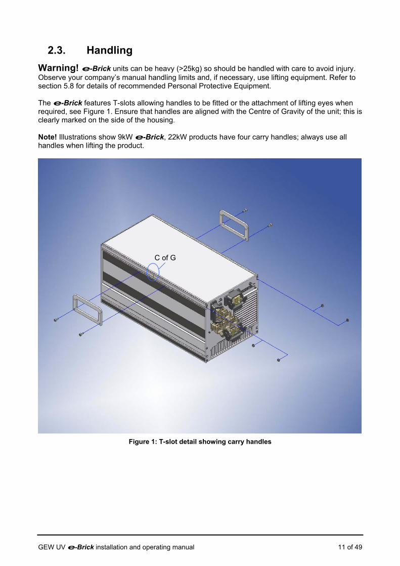
2.3. Handling Warning! e-Brick units can be heavy (>25kg) so should be handled with care to avoid injury. Observe your company’s manual handling limits and, if necessary, use lifting equipment. Refer to section 5.8 for details of recommended Personal Protective Equipment. The e-Brick features T-slots allowing handles to be fitted or the attachment of lifting eyes when required, see Figure 1. Ensure that handles are aligned with the Centre of Gravity of the unit; this is clearly marked on the side of the housing. Note! Illustrations show 9kW e-Brick, 22kW products have four carry handles; always use all handles when lifting the product.
G
Figure
GEW UV e-Brick installation and ope
C of
1: T-slot detail showing carry handles
rating manual 11 of 49

3. Installation & Commissioning During installation and throughout the working life of the UV system, observe the following:
• Avoid knocking or banging the e-Brick or UV dryers • Always keep service cables and ducting away from busy areas such as walkways, and
away from potential hazards such as forklifts • When moving the equipment, never strain cables or unscrew quick release plugs • Apply power to the system only when all connections have been made and tested.
Note! Illustrations show the 9kW e-Brick, 12 and 22kW products are installed in a similar manner but their additional size and mass must be taken in to account.
3.1. Fixing / anchoring Depending on the application the e-Brick can be freestanding or permanently mounted inside a cabinet, e.g. an individual print station.
3.1.1. Freestanding applications For freestanding use, the shelf or surface should be stable and capable of bearing the full weight of the e-Brick(s) and associated cabling. Units may be stacked a maximum of four high using the location features on the top and base of the housing. To ensure stability the carry handles act as fishplates to lock the units together, see Figure 2.
GEW UV e-Brick installation and operating manual 12 of 49
Figure 2: Stacking

3.1.2. Fitment of optional feet
To position an e-Brick stack off the ground, four of the ‘handle’ components (GEW part 24974) may be attached to the housing using the T-slots on the base of the unit.
Figure 3: Fitment of optional feet
GEW UV e-Brick installation and operating manual 13 of 49
3.1.3. Permanent Mounting
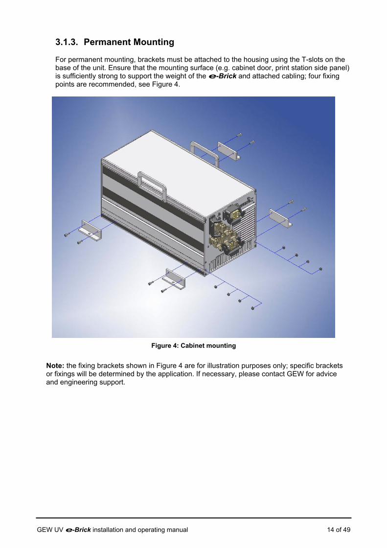
For permanent mounting, brackets must be attached to the housing using the T-slots on the base of the unit. Ensure that the mounting surface (e.g. cabinet door, print station side panel) is sufficiently strong to support the weight of the e-Brick and attached cabling; four fixing points are recommended, see Figure 4.
Figure 4: Cabinet mounting
Note: the fixing brackets shown in Figure 4 are for illustration purposes only; specific brackets or fixings will be determined by the application. If necessary, please contact GEW for advice and engineering support.
GEW UV e-Brick installation and operating manual 14 of 49

3.2. Space needed for use and maintenance The e-Brick requires little maintenance following installation but clearance is required to allow adequate cooling of the internal electronics. Allow the following clearances (see Figure 5):
>500mm from the air intake >300mm from the exhaust outlet >25mm from sides
If the e-Brick will be mounted in an enclosure rather than in free air, it is essential that adequate ventilation is provided. Refer to Table 2 for the rated power dissipation for each product variant; this figure should be taken in to account when calculating overall system cooling requirements.
e-Brick variant Power dissipation (W) 3.6kW 300 9kW 475 12kW 900 22kW 1500
Table 2: Power dissipation
Figure 5: Installation clearances
GEW UV e-Brick installation and operating manual 15 of 49
3.3. Environmental conditions 3.3.1. Temperature
Operating temperature range is +5°C to +40°C
3.3.2. Humidity
Relative Humidity (RH) <50% at +40°C, non-condensing
3.3.3. Altitude
To a maximum of 1000m above mean sea level
3.3.4. Contaminants
Filters are provided to protect the e-Brick against moisture and dust ingress to IP32 in accordance with EN60529.
3.3.5. Vibration, shock and bump
It is recommended that the e-Brick should be installed in a location where vibration is minimized and there is minimal risk of shock or bump forces. If vibration is excessive for a given installation, anti-shock mountings may be required.
3.3.6. Electromagnetic compatibility
The e-Brick is designed to comply with the relevant EMC legislation for industrial installations:
EN61000-6-4:2001 EMC – Emission Standard for industrial environments EN61000-6-2:2001 EMC – Immunity for industrial environments
GEW UV e-Brick installation and operating manual 16 of 49
3.4. Connection to power supply Warning! A qualified electrician must make the connection to the mains supply. The 9/12/22kW e-Brick requires a 3-Phase mains supply with a Protective Earth connection (3P+E); note that no neutral connection is made. The 3.6kW e-Brick requires a single-phase mains supply with a Protective Earth connection. All variants require: 1) Permanently installed wiring fed by a suitably rated Miniature Circuit Breaker (MCB) to protect each phase of the incoming mains supply cable and allow isolation of an individual e-Brick. For North America and Canada Moulded Case Circuit Breakers (MCCB) shall be used for branch circuit protection. 2) A suitably rated supply disconnection device to allow isolation of the mains supply to the e-Brick installation. It is recommended that this shall be easily accessible by the operator.
3.4.1. Essential electrical installation data
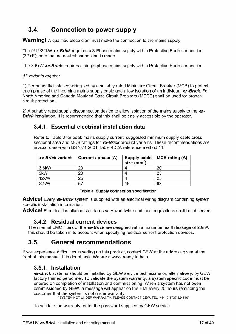
Refer to Table 3 for peak mains supply current, suggested minimum supply cable cross sectional area and MCB ratings for e-Brick product variants. These recommendations are in accordance with BS7671:2001 Table 4D2A reference method 11.
e-Brick variant Current / phase (A) Supply cable
size (mm2) MCB rating (A)
3.6kW 20 4 20 9kW 20 4 25 12kW 25 4 25 22kW 57 16 63
Table 3: Supply connection specification
Advice! Every e-Brick system is supplied with an electrical wiring diagram containing system specific installation information. Advice! Electrical installation standards vary worldwide and local regulations shall be observed.
3.4.2. Residual current devices The internal EMC filters of the e-Brick are designed with a maximum earth leakage of 20mA; this should be taken in to account when specifying residual current protection devices.
3.5. General recommendations If you experience difficulties in setting up this product, contact GEW at the address given at the front of this manual. If in doubt, ask! We are always ready to help.
3.5.1. Installation e-Brick systems should be installed by GEW service technicians or, alternatively, by GEW factory trained personnel. To validate the system warranty, a system specific code must be entered on completion of installation and commissioning. When a system has not been commissioned by GEW, a message will appear on the HMI every 20 hours reminding the customer that the system is not under warranty:
“SYSTEM NOT UNDER WARRANTY. PLEASE CONTACT GEW, TEL: +44 (0)1737 824510”
To validate the warranty, enter the password supplied by GEW service. GEW UV e-Brick installation and operating manual 17 of 49

3.5.2. Modifications
Each GEW UV system is engineered to meet the requirements of a given installation. Any change in requirements may require re-commissioning or modification of the system; always refer to GEW for advice before attempting to modify the UV system.
3.5.3. Markings and tamper evident seals GEW products are clearly marked with safety warnings to draw attention to specific hazards. Due to the hazardous voltages within the e-Brick, security screws are used to secure the housing; in addition, tamper evident seals (see Figure 6) are fitted to indicate that covers have been removed. If these seals are broken or damaged the GEW warranty will be void.
Figure 6: Tamper evident seal
3.5.4. Location of equipment The user should ensure that no electrical controls are obstructed. Always site equipment to allow reasonable access for servicing. The installer should ensure that clearances around the equipment fall within the safety regulations for use of electrical equipment. Impact from vehicles such as forklift trucks must be prevented, typically by installing a protective crash barrier. This is the responsibility of the customer.
Loose cables between distribution panels, the printing machine and the UV dryers must be protected by galvanized trunking. This is the responsibility of the customer.
3.6. Waste removal & disposal Refer to Table 4 for information on recycling e-Brick packaging materials.
Standard Packaging Material Recycle method Cardboard outer container Corrugated
tri-wall cardboard
Cardboard recycling facilities exist in most areas
Moulded end cap “Stratocell” Polyethylene foam
May be recycled where facilities exist Alternatively, dispose of in normal industrial waste stream
Plastic bag Polythene May be recycled where facilities exist Silica gel sachet Silica gel /
paper sachet Dispose of in normal industrial waste stream
Pallet Timber GEW pallets are suitable for reuse. Alternatively, recycling facilities exist in most areas
Table 4: Recycling standard packaging GEW UV e-Brick installation and operating manual 18 of 49
4. Product information
4.1. Description of the e-Brick The e-Brick is a highly integrated power supply designed specifically for powering GEW UV lamps in drying systems. The e-Brick features integrated controls and all necessary hardware to control the UV system including lamp cooling, safety interlock features, and a press interface allowing the UV curing to be controlled automatically.
4.2. Applications The e-Brick is specifically designed for powering GEW UV dryers and, in certain applications, IR dryers; contact GEW for details of compatible UV and IR dryers. Warning! System efficiency and safety may be compromised and/or the e-Brick may be damaged by the use of non-genuine GEW UV lamps or dryers.
4.3. Prohibited usages All applications, other than those specifically detailed in 4.2 above are prohibited. Please contact GEW for engineering support for all other applications.
4.4. Safety features Warning! To avoid accident or injury, do not attempt to bypass any safety function. The e-Brick is designed to be safe in normal operation and to ‘fail safe’ in the event of adverse operating conditions or internal failure. The following safety features are included:
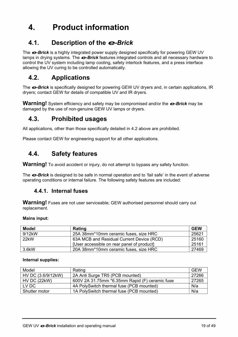
4.4.1. Internal fuses Warning! Fuses are not user serviceable; GEW authorised personnel should carry out replacement. Mains input: Model Rating GEW 9/12kW 25A 38mm*10mm ceramic fuses, size HRC 25621 22kW 63A MCB and Residual Current Device (RCD)
[User accessible on rear panel of product] 25160 25161
3.6kW 20A 38mm*10mm ceramic fuses, size HRC 27469 Internal supplies: Model Rating GEW HV DC (3.6/9/12kW) 2A Anti Surge TR5 (PCB mounted) 27266 HV DC (22kW) 600V 2A 31.75mm *6.35mm Rapid (F) ceramic fuse 27265 LV DC 4A PolySwitch thermal fuse (PCB mounted) N/a Shutter motor 1A PolySwitch thermal fuse (PCB mounted) N/a
GEW UV e-Brick installation and operating manual 19 of 49
4.4.2. Indicators The e-Brick has three LED indicators on the rear panel, “24V” is green when the internal 24V supply is on, “K1” is green when the main contactor in the e-Brick is enabled; the third LED, “OK”, is green in normal operation but red when a fault occurs.
4.4.3. System Emergency stop
The e-Brick can only be enabled if the system emergency stop (E-stop) contacts on the Press connector [P1] are closed, enabling the internal safety relay. The internal controls monitor the E-stop status using auxiliary contacts on the safety relay; as a safety measure, the relay can still disable the supply in the event of a control failure. Warning! Refer to 5.4 for essential safety information relating to E-stop usage.
4.4.4. Contactor
The 3phase power to the main converter in the e-Brick is switched on using an internal contactor. By design, the contactor coil can only be energised when the press E-stop is enabled and a second relay is switched on. The second relay is switched on by the embedded controller and is enabled from the HMI screen. 4.4.5. Temperature & cooling
Fan failure detection Generates warning to HMI Internal temperature warning Generates warning to HMI Over temperature trip Automatic shutdown of e-Brick
4.4.6. Output protection
Voltage limit Output voltage is limited to a specified maximum Current limit Output current is limited to specified maximum Short circuit protection Output circuitry will tolerate an indefinite short circuit Warning! Under no circumstances should either lamp output terminal be electrically connected to chassis ground; this will invalidate the e-Brick warranty and is likely to result in severe damage to the e-Brick.
GEW UV e-Brick installation and operating manual 20 of 49

4.5. General Data 4.5.1. Electrical supply
The 9/12/22kW e-Brick requires a 3-Phase mains supply with a Protective Earth connection (3P+E); note that no neutral connection is made. The 3.6kW e-Brick requires a single-phase mains supply with a Protective Earth connection. Refer to Table 5 for operating Voltage range and peak supply current per phase. Power factor is typically 0.9 for all e-Brick variants so no additional power factor correction is required.
e-Brick variant
Nominal Supply Voltage (V)
Supply Voltage (V)
Peak current / phase (A)
Supply Frequency
Maximum Power
3.6kW 240V 216-264V 20 50-60Hz <4kW 9kW 415V 374-528V 25 50-60Hz <9.6kW 12kW 415V 374-528V 25 50-60Hz <13.1kW 22kW 415V 374-528V 57 50-60Hz <24kW
Table 5: Electrical supply data
Advice! The actual current consumption of the e-Brick is dependent on the supply voltage and the power level demanded by the installation. Please contact GEW service for the actual running current for any specific UV system configuration.
4.5.2. Performance Ratings
Refer to GEW for e-Brick performance data; performance is maintained for the full operating voltage range detailed in Table 5
e-Brick variant
Output voltage (V)
Output current (A)
Efficiency (%)
3.6kW 9kW 12kW 22kW
Refer to GEW
Table 6: Performance data
4.5.3. Noise & Vibration
The e-Brick contains fans to cool the power electronics, these generate some noise but this is likely to be insignificant in the context of the environment the product is installed in.
e-Brick variant
Fans Noise level (dBA @ 1m)**
3.6kW 2 60.8dBA 9kW 2 60.8dBA 12kW 4 68.2dBA 22kW 6 71.7dBA
** Measured in open environment at 1m from air intake: ambient noise level ~48dBA
GEW UV e-Brick installation and operating manual 21 of 49
4.5.4. Radiation
In normal use, the e-Brick generates electromagnetic radiation within allowable limits; refer to 3.3.6 for relevant standards. Warning! The e-Brick forms part of a GEW UV drying system, providing essential safety functions. The UV dryer in the system presents some risk of exposure to UV radiation; this risk is minimised by application specific shielding. Refer to the relevant UV dryer user guides and system installation manuals for further information. 4.5.5. Gases, Vapours, Dust
The e-Brick power supply does not generate any gases, vapours or dust. Refer to 3.3.4 for recommended operating environment and exposure limits for contaminants. Note that UV dryers will generate some Ozone (O3) that is extracted to atmosphere by the cooling system. Refer to the relevant UV dryer user guides and system installation manuals for further information.
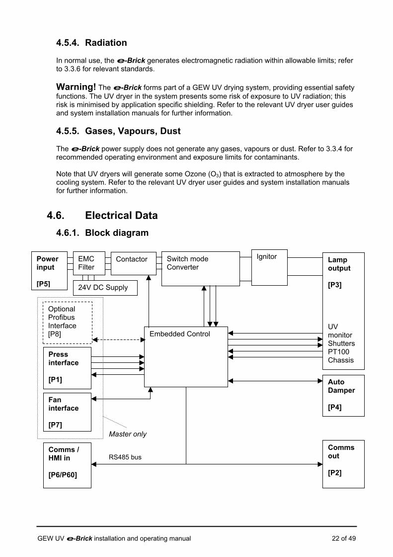
4.6. Electrical Data 4.6.1. Block diagram
Contactor Switch mode Converter
Ignitor Lamp output [P3] 24V DC Supply
EMC Filter
Power input [P5]
Embedded Control
Press interface [P1]
UV monitor Shutters PT100 Chassis
Auto Damper [P4]
Optional Profibus Interface [P8]
GE
Fan interface [P7]
Master only
RS485 bus Comms out [P2]
Comms / HMI in [P6/P60]
W UV e-Brick installation and operating manual 22 of 49
4.6.2. Interface details
Refer to sections 4.6.3.1 to 4.6.3.9 for connection details for P1 to P8 on the e-Brick; Figure 7 shows the positions of the connectors on the rear panel for the 3.6/9/12kW products. Connectors are arranged differently for the 22kW e-Brick, refer to Figure 7(a). P1, P2, P4, P6, P7, P8 are identical; P5 (Power input) and P3 (Lamp output) are functionally identical but have larger connectors and terminal inserts to handle higher voltages and currents. Please note the following: Note! These connections apply to e-Brick products with embedded control electronics 29328/29355 (3.6kW), 28496/28497 (9kW), 28524/28525 (12kW) and 9/12/22kW derivatives. Refer to e-brick user manual rev2.1 for 26365 & 26366 (12kW), 26367, 26368 & 26391 (9kW), 25158 & 26790 (22kW) and derivatives of these models. Refer to issue 1.0 of this manual for connection details of 23326 & 23329 (12kW), 24101, 24104 & 26376 (9kW). Warning! Where ‘Volt free’ outputs are specified, the maximum contact rating of the internal relay contact is provided in the tables below; if this rating is exceeded contact damage may occur and the GEW warranty will be void.
Warning! To ensure isolation of the e-Brick from external systems, where a ‘Volt free’ contact input is specified the externally connected equipment should be interfaced by a relay capable of switching 24Vdc at <0.5A. Applying voltages to these inputs may cause serious damage to the e-Brick and invalidate the GEW warranty.
4.6.3. SELV ports
The e-Brick internal 24V power supply is classified as Safety Extra Low Voltage (SELV) in accordance with clause 2.3 of EN60950. The e-Brick is designed for connection of GEW approved equipment only to ports P1-P8. With the exception of lamp output terminals [P3A-B] and mains input terminals [P5A (3.6/9/12kW) or P5 A-C (22kW)] interfaces are SELV; it is recommended that connections are only made to equipment that complies with the SELV safety classification. Certain ports may exceed SELV voltages (30VDC 60Vrms) within the specified ratings shown in 4.6.3.1 to 4.6.3.9.
GEW UV e-Brick installation and operating manual 23 of 49

P1,P6,P7 only fitted on master e-brick
6
7
LED: K1 24V OK DIPswitch cover plate
5
Figure 7: Rear pan
Figure 7(a): Rear panel (22k
GEW UV e-Brick installation and operating manual
P8
3
el connection details
8
P1 & P7 only fitted on master
W Master) connection details
P8 only fitted on Profibus master e-brick
P8 only fitted on Profibus master e-brick
PE
K1 24VP6
P2 P4P3
P5
P
P7
P1P1
P60P
P2 P4P
P
P
24 of 49
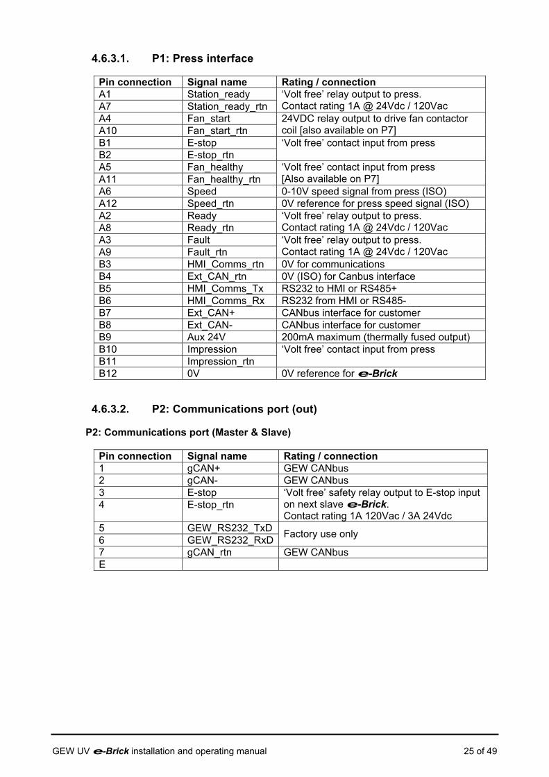
4.6.3.1. P1: Press interface
Pin connection Signal name Rating / connection A1 Station_ready A7 Station_ready_rtn
‘Volt free’ relay output to press. Contact rating 1A @ 24Vdc / 120Vac
A4 Fan_start A10 Fan_start_rtn
24VDC relay output to drive fan contactor coil [also available on P7]
B1 E-stop B2 E-stop_rtn
‘Volt free’ contact input from press
A5 Fan_healthy A11 Fan_healthy_rtn
‘Volt free’ contact input from press [Also available on P7]
A6 Speed 0-10V speed signal from press (ISO) A12 Speed_rtn 0V reference for press speed signal (ISO) A2 Ready A8 Ready_rtn
‘Volt free’ relay output to press. Contact rating 1A @ 24Vdc / 120Vac
A3 Fault A9 Fault_rtn
‘Volt free’ relay output to press. Contact rating 1A @ 24Vdc / 120Vac
B3 HMI_Comms_rtn 0V for communications B4 Ext_CAN_rtn 0V (ISO) for Canbus interface B5 HMI_Comms_Tx RS232 to HMI or RS485+ B6 HMI_Comms_Rx RS232 from HMI or RS485- B7 Ext_CAN+ CANbus interface for customer B8 Ext_CAN- CANbus interface for customer B9 Aux 24V 200mA maximum (thermally fused output) B10 Impression B11 Impression_rtn
‘Volt free’ contact input from press
B12 0V 0V reference for e-Brick
4.6.3.2. P2: Communications port (out)
P2: Communications port (Master & Slave)
Pin connection Signal name Rating / connection 1 gCAN+ GEW CANbus 2 gCAN- GEW CANbus 3 E-stop 4 E-stop_rtn
‘Volt free’ safety relay output to E-stop input on next slave e-Brick. Contact rating 1A 120Vac / 3A 24Vdc
5 GEW_RS232_TxD 6 GEW_RS232_RxD Factory use only
7 gCAN_rtn GEW CANbus E
GEW UV e-Brick installation and operating manual 25 of 49
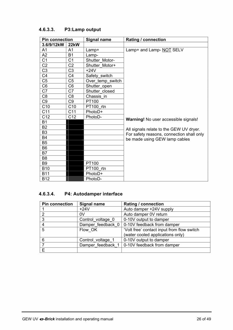
4.6.3.3. P3:Lamp output
Pin connection Signal name Rating / connection 3.6/9/12kW 22kW A1 A1 Lamp+ A2 B1 Lamp- C1 C1 Shutter_Motor- C2 C2 Shutter_Motor+ C3 C3 +24V C4 C4 Safety_switch C5 C5 Over_temp_switchC6 C6 Shutter_open C7 C7 Shutter_closed C8 C8 Chassis_in C9 C9 PT100 C10 C10 PT100_rtn C11 C11 PhotoD+ C12 C12 PhotoD- B1 B2 B3 B4 B5 B6 B7 B8 B9 PT100 B10 PT100_rtn B11 PhotoD+ B12 PhotoD-
Lamp+ and Lamp- NOT SELV Warning! No user accessible signals! All signals relate to the GEW UV dryer. For safety reasons, connection shall only be made using GEW lamp cables
4.6.3.4. P4: Autodamper interface
Pin connection Signal name Rating / connection 1 +24V Auto damper +24V supply 2 0V Auto damper 0V return 3 Control_voltage_0 0-10V output to damper 4 Damper_feedback_0 0-10V feedback from damper 5 Flow_OK ‘Volt free’ contact input from flow switch
(water cooled applications only) 6 Control_voltage_1 0-10V output to damper 7 Damper_feedback_1 0-10V feedback from damper E
GEW UV e-Brick installation and operating manual 26 of 49

4.6.3.5. P5: Power input
Pin connection Signal name Rating / connection 9/12kW 3.6kW 22kW A1 A1 A1 L1 A2 B1 L2 A3 C1 L3 A2 N
Mains supply input, for ratings see Table 5 L1-L3 & N connections NOT SELV
Frame Frame Frame PE B1 B1 F1 Fan_healthy B2 B2 F2 Fan_healthy_rtn
Volt free’ contact input from press [Also available on P7]
B3 B3 F3 Auxiliary_n/o B4 B4 F4 Auxiliary_n/o_rtn
‘Volt free’ auxiliary n/o contact output. Contact rating 1A @ 24Vdc / 120Vac
B5 B5 F5 Auxiliary_n/c B6 B6 F6
Auxiliary_n/c_rtn
‘Volt free’ auxiliary n/c contact output. Contact rating 1A @ 24Vdc / 120Vac
B7 B7 F7 Chiller_OK B8 B8 F8 Chiller_OK_rtn
‘Volt free’ contact input from chiller
4.6.3.6. Protective Earth terminal
An M6 stud is provided on the rear of the e-Brick housing to permit Protective Earth (PE) bonding during installation. Note that the mains supply earth is through P5.
4.6.3.7. P6(P60): Communication port (in)
P6: HMI (Master) Pin connection Signal name (Master) Rating / connection 1 24V 24V output to HMI 2 0V 0V output to HMI 3 HMI_Comms_Tx RS232 to HMI or RS485+ 4 HMI_Comms_Rx RS232 from HMI or RS485- 5 Ext_CAN+ CANbus interface for customer 6 Ext_CAN- CANbus interface for customer 7 HMI_Comms_rtn 0V for communications E
P60: Communications port (Slave, in) Pin connection Signal name (Slave) Rating / connection 1 gCAN+ GEW CANbus 2 gCAN- GEW CANbus 3 E-stop 4 E-stop_rtn
‘Volt free’ contact input from E-stop output on previous master / slave e-Brick.
5 N/c 6 N/c 7 gCAN_rtn GEW CANbus E
GEW UV e-Brick installation and operating manual 27 of 49

4.6.3.8. P7: System fan interface
Pin connection Signal name Rating / connection 1 Fan_healthy 2 Fan_healthy_rtn
‘Volt free’ contact input from fan overload auxiliary [Also available on P1,P5]
3 Fan_start out 7 Fan_start_rtn
24VDC relay output to drive fan contactor coil. [Also available on P1,P5]
4 N/c 5 Frame_safety_switch 6 Frame_safety_switch_rtn
‘Volt free’ contact input from optional frame safety switch
E
4.6.3.9. P8: Profibus interface
Where an e-Brick is supplied with an internal Profibus interface, connection to the external system is made by a standard 9 way ‘D’ type connector (not shown in Figure 7).
Pin connection Signal name (Slave) Rating / connection 1 MON_RS232_Tx 2 MON_RS232_Rx 7 MON_RS232_0V
Factory use only
3 Profibus_B 4 Profibus_RTS 5 Profibus_GND 6 Profibus_5V 8 Profibus_A 9 N/c Housing Profibus_cable_shield
Profibus network
GEW UV e-Brick installation and operating manual 28 of 49
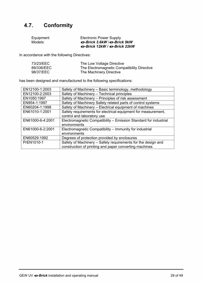
4.7. Conformity
Equipment Electronic Power Supply Models: e-Brick 3.6kW /e-Brick 9kW
e-Brick 12kW / e-Brick 22kW In accordance with the following Directives:
73/23/EEC The Low Voltage Directive 89/336/EEC The Electromagnetic Compatibility Directive 98/37/EEC The Machinery Directive
has been designed and manufactured to the following specifications:
EN12100-1:2003 Safety of Machinery – Basic terminology, methodology EN12100-2:2003 Safety of Machinery – Technical principles EN1050:1997 Safety of Machinery – Principles of risk assessment EN954-1:1997 Safety of Machinery Safety related parts of control systems EN60204-1:1998 Safety of Machinery – Electrical equipment of machines EN61010-1:2001 Safety requirements for electrical equipment for measurement,
control and laboratory use EN61000-6-4:2001 Electromagnetic Compatibility – Emission Standard for industrial
environments EN61000-6-2:2001 Electromagnetic Compatibility – Immunity for industrial
environments EN60529:1992 Degrees of protection provided by enclosures PrEN1010-1 Safety of Machinery – Safety requirements for the design and
construction of printing and paper converting machines
GEW UV e-Brick installation and operating manual 29 of 49
5. Product application
5.1. Intended use of the e-Brick The e-Brick is specifically designed for powering GEW UV dryers and, in certain applications, IR dryers; contact GEW for details of compatible UV and IR dryers. The e-Brick power supply is a component part of a GEW UV drying system. A complete system would also include GEW UV dryer(s) e.g. VCP, custom cabling, fan cooling, ducting and a human machine interface (HMI) to control the operation of the system. Systems vary in complexity and the scope of supply differs depending on the application. This manual should be referred to alongside the user manuals and installation information for the other components in the system.
5.2. Manual controls The e-Brick has no manual controls; operation is controlled by the GEW system HMI. In some applications an RS485 based serial data protocol may be implemented on the customers HMI.
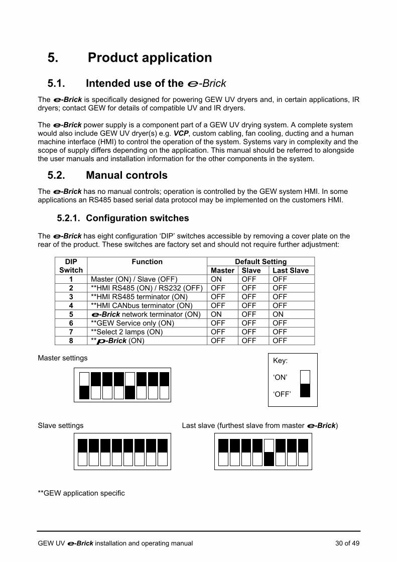
5.2.1. Configuration switches The e-Brick has eight configuration ‘DIP’ switches accessible by removing a cover plate on the rear of the product. These switches are factory set and should not require further adjustment:
Default Setting DIP Switch
Function Master Slave Last Slave
1 Master (ON) / Slave (OFF) ON OFF OFF 2 **HMI RS485 (ON) / RS232 (OFF) OFF OFF OFF 3 **HMI RS485 terminator (ON) OFF OFF OFF 4 **HMI CANbus terminator (ON) OFF OFF OFF 5 e-Brick network terminator (ON) ON OFF ON 6 **GEW Service only (ON) OFF OFF OFF 7 **Select 2 lamps (ON) OFF OFF OFF 8 **p-Brick (ON) OFF OFF OFF
Master settings Slave settings Last slave (furthest slave from master e-Brick)
Key: ‘ON’ ‘OFF’
**GEW application specific
GEW UV e-Brick installation and operating manual 30 of 49
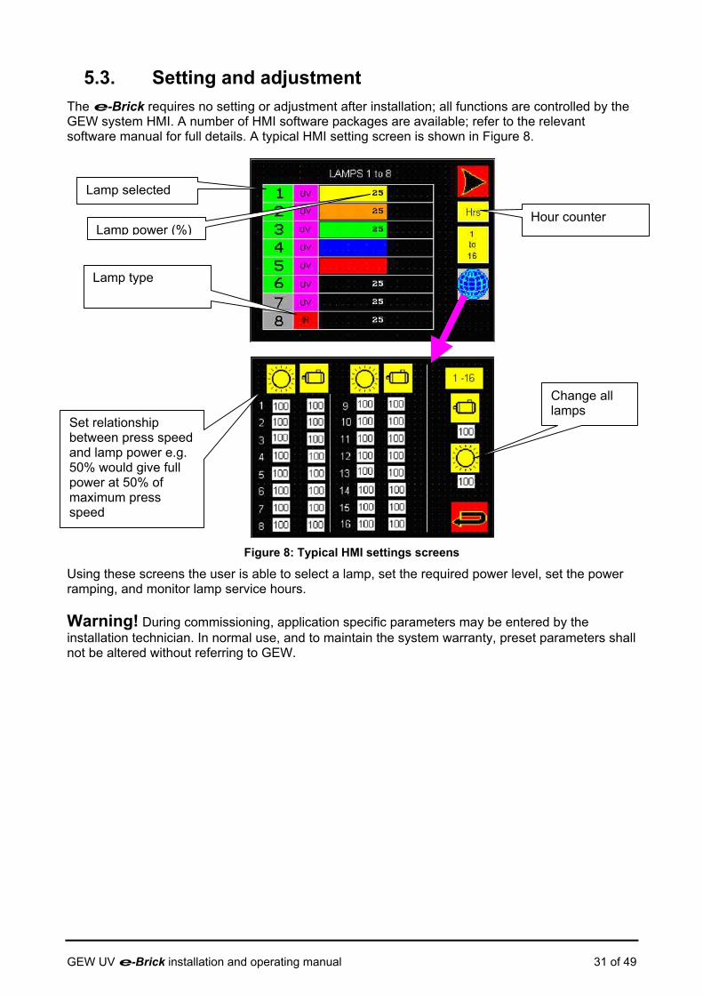
5.3. Setting and adjustment The e-Brick requires no setting or adjustment after installation; all functions are controlled by the GEW system HMI. A number of HMI software packages are available; refer to the relevant software manual for full details. A typical HMI setting screen is shown in Figure 8.
Lamp selected
Lamp power (%) Hour counter
Lamp type
Change all lamps
Set relationship between press speed and lamp power e.g. 50% would give full power at 50% of maximum press speed
Figure 8: Typical HMI settings screens
Using these screens the user is able to select a lamp, set the required power level, set the power ramping, and monitor lamp service hours. Warning! During commissioning, application specific parameters may be entered by the installation technician. In normal use, and to maintain the system warranty, preset parameters shall not be altered without referring to GEW.
GEW UV e-Brick installation and operating manual 31 of 49
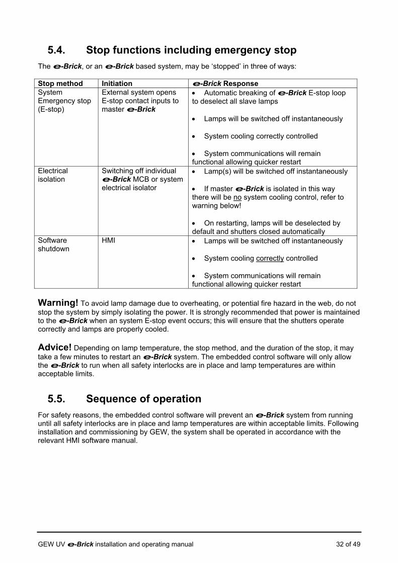
5.4. Stop functions including emergency stop The e-Brick, or an e-Brick based system, may be ‘stopped’ in three of ways: Stop method Initiation e-Brick Response System Emergency stop (E-stop)
External system opens E-stop contact inputs to master e-Brick
• Automatic breaking of e-Brick E-stop loop to deselect all slave lamps • Lamps will be switched off instantaneously • System cooling correctly controlled • System communications will remain functional allowing quicker restart
Electrical isolation
Switching off individual e-Brick MCB or system electrical isolator
• Lamp(s) will be switched off instantaneously • If master e-Brick is isolated in this way there will be no system cooling control, refer to warning below! • On restarting, lamps will be deselected by default and shutters closed automatically
Software shutdown
HMI • Lamps will be switched off instantaneously • System cooling correctly controlled • System communications will remain functional allowing quicker restart
Warning! To avoid lamp damage due to overheating, or potential fire hazard in the web, do not stop the system by simply isolating the power. It is strongly recommended that power is maintained to the e-Brick when an system E-stop event occurs; this will ensure that the shutters operate correctly and lamps are properly cooled. Advice! Depending on lamp temperature, the stop method, and the duration of the stop, it may take a few minutes to restart an e-Brick system. The embedded control software will only allow the e-Brick to run when all safety interlocks are in place and lamp temperatures are within acceptable limits.
5.5. Sequence of operation For safety reasons, the embedded control software will prevent an e-Brick system from running until all safety interlocks are in place and lamp temperatures are within acceptable limits. Following installation and commissioning by GEW, the system shall be operated in accordance with the relevant HMI software manual.
GEW UV e-Brick installation and operating manual 32 of 49

5.6. Risk Reduction The GEW engineering team has considered safety of the equipment at every stage of the design process. However, certain hazards remain because of the nature of the application. To avoid accident or injury, operators should be aware of the hazards associated with UV drying systems.
5.6.1. Remaining risks, Hazard reduction and safeguards
The remaining hazards are associated with Ozone, Mercury, Ultra-Violet Radiation (UVR), moving parts, high temperatures, and high voltages.
5.6.1.1. Ozone (O3)
Warning! The UV lamp generates Ozone; the gas is normally ducted to atmosphere along with the exhaust air. Alternatively, air may be safely discharged to the factory via an Ozone filter. Ozone irritates the lungs; if a pungent smell of Ozone is detected check the ducting for air tightness. Ensure that the ducting is correctly installed and in place at all times. If ozone filters are fitted, ensure they are changed according to the maintenance schedules set out in the installation manual.
5.6.1.2. Mercury (Hg)
Warning! UV lamps contain small quantities of Mercury, which is a toxic substance must be handled carefully. Always wash hands thoroughly after handling UV lamps. Dispose of broken lamps safely by the following means: Wear heavy rubber gloves at all times:
• Cover the mercury and broken glass with sand. • Collect the waste mixture with dustpan and brush, and transfer it to a cardboard box
or other expendable container. • To protect the refuse operator, put the container in a thick plastic bag.
Dispose of the bagged container with the normal industrial waste, or in accordance with local arrangements for disposal of mercury.
5.6.1.3. Ultra-Violet Radiation (UVR)
Warning! Ultra violet radiation (UVR) is harmful to skin and eyes. UV dryers have adequate shielding fitted to prevent accidental exposure of the operator to UVR, but it is essential to take care when operating the UV drying system. UVR is present in the ranges UV-A, UV-B, UV-C and UV-V. Observe the following:
• Ensure that the shielding is kept in place at all times and is properly adjusted • Do not look directly into the lamp head while the lamp is on • Avoid prolonged exposure of your hands in the area along the light shields • Wear protective clothing and eye protection if prolonged exposure is unavoidable
GEW UV e-Brick installation and operating manual 33 of 49

5.6.1.4. Moving parts
Warning! Cooling fans are supplied with inlet and outlet ports uncovered; take care when fitting ducting to these ports. Fans should never be run with ports uncovered; this may cause injury by ejecting loose objects at high speed or trapping the hands.
5.6.1.5. High temperatures
Warning! Hot surfaces and electrical energy can cause fires to break out. High temperatures occur inside the UV dryer. Allow the dryer to cool from full power for five minutes before attempting to remove or open any lamp head, then proceed with caution. Operators should always be vigilant. NEVER use flammable solvents near the UV dryers when the lamps are in operation. If a fire should break out, follow the procedure posted for the building.
Only fire extinguishers of the dry powder type should be used on this equipment.
5.6.1.6. High voltages
Warning! UV lamps operate at high voltages, typically 450V to 1400V depending on lamp type; additionally when striking the lamps, ignitor circuitry will generate pulses in excess of 2kV. These voltages present a possible danger of electric shock or fire. Do not mount other equipment so that it could interfere with the safe operation of the system. When testing or troubleshooting, all safety interlocks shall be in place and cables left intact.
5.6.2. Misuse and prohibited usages
The e-Brick is designed solely intended for powering specific GEW UV and IR dryers. All other applications are prohibited, unless prior written consent has been obtained from GEW.
5.7. Fault identification and repair Warning! There are no user serviceable parts inside the e-Brick; do not remove covers under any circumstances. Please note that if factory security seals are broken, the warranty is void. Refer to GEW or your local agent for service.
5.8. Personal Protective Equipment Due to their weight, it is advisable to wear safety shoes when installing e-Brick products. Warning! Other protective equipment may be required while installing an e-Brick system. If necessary, consult your local Health and Safety representative for advice.
5.9. Training required Although designed for ease of installation, GEW systems should be installed and commissioned by GEW service technicians. Alternatively some customers and OEMs have their own GEW trained personnel. Please contact GEW Customer Service for information on installation training for your GEW UV system.
GEW UV e-Brick installation and operating manual 34 of 49

6. Maintenance information
Warning! There are no user serviceable parts inside the e-Brick; do not remove covers under any circumstances. Please note that if factory security seals are broken, the warranty is void. Refer to GEW or your local agent for service.
6.1. Safety inspections The e-Brick forms part of a UV drying system which requires inspection operations in accordance with the schedule in section 10.
6.2. Functional Testing The e-Brick forms part of a UV drying system which requires functional testing in accordance with the schedule in section 10.
6.3. Specialist inspection & repair For attention of GEW (EC) Limited service department:
•
Warning ! Danger of electric shock or death Observe the following during service operations:
• Isolate the unit from the mains before attempting maintenance, removing covers, cables, or light shielding
• Ensure that the internal capacitors have been discharged by leaving the system switched off for 5 minutes before carrying out any maintenance.
• Isolation transformers shall be used at all times when working on live equipment. Alternatively a mains supply with appropriate earth leakage protection (30mA RCD) may be used.
• Use only approved, calibrated test equipment
• Use only approved components during maintenance
• Always replace security seals after service operations
6.3.1. Firmware update GEW service technicians may update the embedded software in an e-Brick system using a PC with suitable software and a data interface cable (GEW part 28628).
6.3.2. Safety devices Refer to section 4.4 for details of the safety devices designed in to the e-Brick. Advice! If any safety feature is compromised or failure suspected, always refer to GEW for service.
GEW UV e-Brick installation and operating manual 35 of 49
6.4. Routine (operator) maintenance The e-Brick forms part of a UV drying system which requires preventative maintenance operations in accordance with the schedule in section 10.
6.4.1. Air filter cleaning / replacement
Warning! Isolate power before changing or checking filters The only components of the e-Brick requiring regular maintenance are the air filters. Filters shall be checked in accordance with the system maintenance schedule in section 10; always follow the procedures in section 9. Advice! Record filter checks and changes for reference in the event of a warranty claim; see section 10.1 for a suggested format.
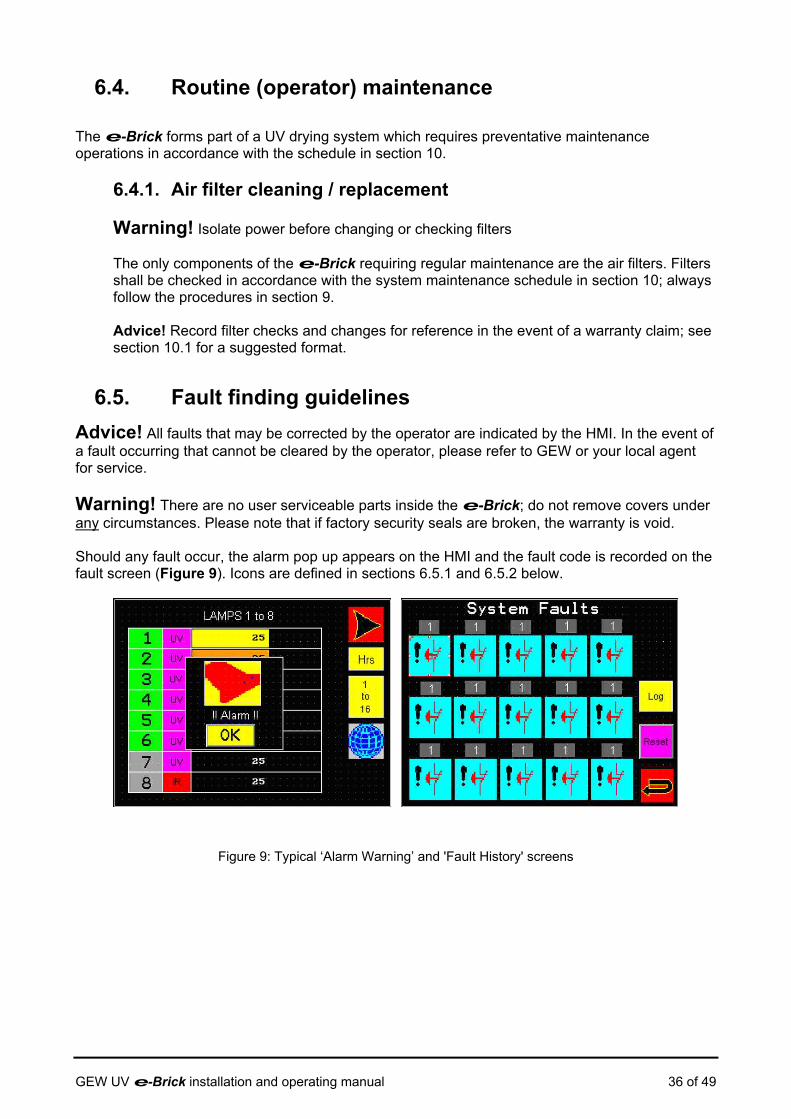
6.5. Fault finding guidelines Advice! All faults that may be corrected by the operator are indicated by the HMI. In the event of a fault occurring that cannot be cleared by the operator, please refer to GEW or your local agent for service. Warning! There are no user serviceable parts inside the e-Brick; do not remove covers under any circumstances. Please note that if factory security seals are broken, the warranty is void. Should any fault occur, the alarm pop up appears on the HMI and the fault code is recorded on the fault screen (Figure 9). Icons are defined in sections 6.5.1 and 6.5.2 below.
Figure 9: Typical ‘Alarm Warning’ and 'Fault History' screens
GEW UV e-Brick installation and operating manual 36 of 49

6.5.1. General faults
Water cooling unit (chiller) failure The cooling unit has failed while the printing machine is running.
• Check chiller MCB and reset if necessary • Ensure that the chiller is switched on • The chiller may have developed a fault; check the control panel to see if a fault is reported • Refer to the chiller manual for further fault finding suggestions
Emergency stop failure The operator may have triggered an emergency stop of the printing machine
• Check external emergency stop (e-stop) circuitry and switches • Check panel circuit breakers in external equipment • Check e-stop links between e-Brick units are intact (communications cables linking master-slave / slave/slave carry the e-Brick e-stop links)
Fan failure The fan fails to operate when a lamp is started. • Check the electrical supply to the fan • Check the MCB supplying power to the fan, reset if necessary • Check the thermal overload device on the fan. If the switch has been tripped, reset it
by pressing “1” button on the switch housing, then reset the fault on the touch screen On systems where an external air handling unit is used in place of the GEW system fan, this fault may show if the cooling air pressure does not reach a predetermined threshold within 90s of starting the cooling system
System Safety Switch
• Check the functionality of the system safety switch • Check integrity of wiring and connectors for the system safety switch
6.5.2. Individual faults
Burn in failure The lamp ‘burns in’ until it reaches a certain operating voltage and running temperature. If the lamp does not reach this voltage within 4 minutes, or achieve temperature within 10 minutes then the lamp will trip and the burn in failure will appear. This type of failure usually occurs if the lamp is overcooled.
• Check that orange damper unit is operating correctly • Check the supply voltage is within the operating voltage range of the e-Brick
and fan as specified on the rating plate
Flow switch failure Cooling water supply to the lamp head has failed.
• Check that water cooling is on • Check that all the hoses are connected to lampheads and cooler • Ensure that all valves are set to the open position • The water flow through the switch may be insufficient, check water hoses for
kinks and blockages
GEW UV e-Brick installation and operating manual 37 of 49
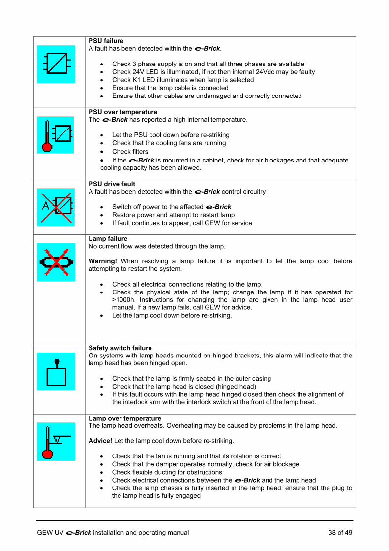
PSU failure A fault has been detected within the e-Brick.
• Check 3 phase supply is on and that all three phases are available • Check 24V LED is illuminated, if not then internal 24Vdc may be faulty • Check K1 LED illuminates when lamp is selected • Ensure that the lamp cable is connected • Ensure that other cables are undamaged and correctly connected
PSU over temperature The e-Brick has reported a high internal temperature.
• Let the PSU cool down before re-striking • Check that the cooling fans are running • Check filters • If the e-Brick is mounted in a cabinet, check for air blockages and that adequate cooling capacity has been allowed.
PSU drive fault A fault has been detected within the e-Brick control circuitry
• Switch off power to the affected e-Brick • Restore power and attempt to restart lamp • If fault continues to appear, call GEW for service
Lamp failure No current flow was detected through the lamp. Warning! When resolving a lamp failure it is important to let the lamp cool before attempting to restart the system.
• Check all electrical connections relating to the lamp. • Check the physical state of the lamp; change the lamp if it has operated for
>1000h. Instructions for changing the lamp are given in the lamp head user manual. If a new lamp fails, call GEW for advice.
• Let the lamp cool down before re-striking.
Safety switch failure On systems with lamp heads mounted on hinged brackets, this alarm will indicate that the lamp head has been hinged open.
• Check that the lamp is firmly seated in the outer casing • Check that the lamp head is closed (hinged head) • If this fault occurs with the lamp head hinged closed then check the alignment of
the interlock arm with the interlock switch at the front of the lamp head.
Lamp over temperature The lamp head overheats. Overheating may be caused by problems in the lamp head. Advice! Let the lamp cool down before re-striking.
• Check that the fan is running and that its rotation is correct • Check that the damper operates normally, check for air blockage • Check flexible ducting for obstructions • Check electrical connections between the e-Brick and the lamp head • Check the lamp chassis is fully inserted in the lamp head; ensure that the plug to
the lamp head is fully engaged
GEW UV e-Brick installation and operating manual 38 of 49
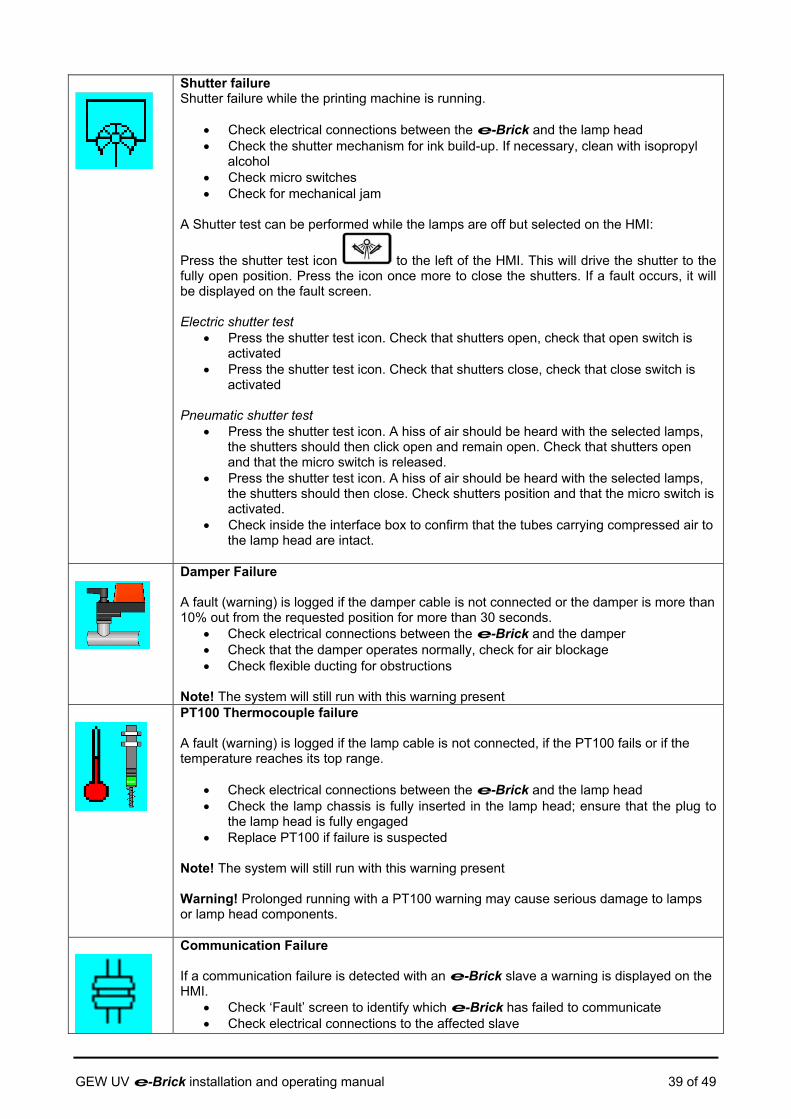
Shutter failure Shutter failure while the printing machine is running.
• Check electrical connections between the e-Brick and the lamp head • Check the shutter mechanism for ink build-up. If necessary, clean with isopropyl
alcohol • Check micro switches • Check for mechanical jam
A Shutter test can be performed while the lamps are off but selected on the HMI:
Press the shutter test icon to the left of the HMI. This will drive the shutter to the fully open position. Press the icon once more to close the shutters. If a fault occurs, it will be displayed on the fault screen. Electric shutter test
• Press the shutter test icon. Check that shutters open, check that open switch is activated
• Press the shutter test icon. Check that shutters close, check that close switch is activated
Pneumatic shutter test
• Press the shutter test icon. A hiss of air should be heard with the selected lamps, the shutters should then click open and remain open. Check that shutters open and that the micro switch is released.
• Press the shutter test icon. A hiss of air should be heard with the selected lamps, the shutters should then close. Check shutters position and that the micro switch is activated.
• Check inside the interface box to confirm that the tubes carrying compressed air to the lamp head are intact.
Damper Failure A fault (warning) is logged if the damper cable is not connected or the damper is more than 10% out from the requested position for more than 30 seconds.
• Check electrical connections between the e-Brick and the damper • Check that the damper operates normally, check for air blockage • Check flexible ducting for obstructions
Note! The system will still run with this warning present
PT100 Thermocouple failure A fault (warning) is logged if the lamp cable is not connected, if the PT100 fails or if the temperature reaches its top range.
• Check electrical connections between the e-Brick and the lamp head • Check the lamp chassis is fully inserted in the lamp head; ensure that the plug to
the lamp head is fully engaged • Replace PT100 if failure is suspected
Note! The system will still run with this warning present Warning! Prolonged running with a PT100 warning may cause serious damage to lamps or lamp head components.
Communication Failure If a communication failure is detected with an e-Brick slave a warning is displayed on the HMI.
• Check ‘Fault’ screen to identify which e-Brick has failed to communicate • Check electrical connections to the affected slave
GEW UV e-Brick installation and operating manual 39 of 49
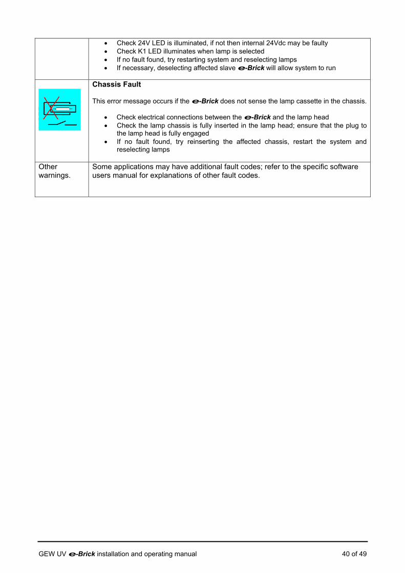
• Check 24V LED is illuminated, if not then internal 24Vdc may be faulty • Check K1 LED illuminates when lamp is selected • If no fault found, try restarting system and reselecting lamps • If necessary, deselecting affected slave e-Brick will allow system to run
Chassis Fault This error message occurs if the e-Brick does not sense the lamp cassette in the chassis.
• Check electrical connections between the e-Brick and the lamp head • Check the lamp chassis is fully inserted in the lamp head; ensure that the plug to
the lamp head is fully engaged • If no fault found, try reinserting the affected chassis, restart the system and
reselecting lamps
Other warnings.
Some applications may have additional fault codes; refer to the specific software users manual for explanations of other fault codes.
GEW UV e-Brick installation and operating manual 40 of 49

6.6. Parts list 6.6.1. Recommended spares
Item GEW part number Notes Intake filter medium 10485 Filter insert Exhaust filter medium 24504 Filter insert (3.6/9/12kW) Exhaust filter medium 25392 Filter insert (22kW)
GEW UV e-Brick installation and operating manual 41 of 49

7. End of life information GEW products are designed for reliability and will, with regular preventive maintenance, provide a long service life. However, in future the host press system and ancillary equipment, such as the UV system, may become surplus to requirement and will need to be dismantled or disposed of.
7.1. De-commissioning, dismantling and disposal Warning! Isolate power before dismantling the UV system. Warning! Before dismantling a UV system refer to section 5.6 on hazards. Having isolated the mains power, the equipment may be dismantled by unplugging connectors and unbolting fixings from the host equipment. As with any complex engineered product the e-Brick contains a number of materials requiring different disposal or recycling methods. In accordance with the European Waste Electrical and Electronic Equipment (WEEE) Directive these materials must be recovered by an approved recycling facility.
Please contact your local authority for details of the nearest licensed recycling facility. Where necessary, and only with prior written consent, equipment may be returned to GEW for recycling.
GEW UV e-Brick installation and operating manual 42 of 49

8. Emergency information
8.1. Fire fighting Warning! Only fire extinguishers of the dry powder type should be used on this equipment.
8.2. Potential hazards The e-Brick is a component of a UV drying system which, although designed for safety, presents some remaining hazards associated with Ozone, Mercury, Ultra-Violet Radiation (UVR), moving parts, high temperatures, and high voltages. As a component of the UV drying system, the specific hazards associated with the e-Brick are high internal voltages, high output voltages to the lamp head, and high internal temperatures resulting from normal heating of electronic components.
GEW UV e-Brick installation and operating manual 43 of 49
9. Maintenance procedures
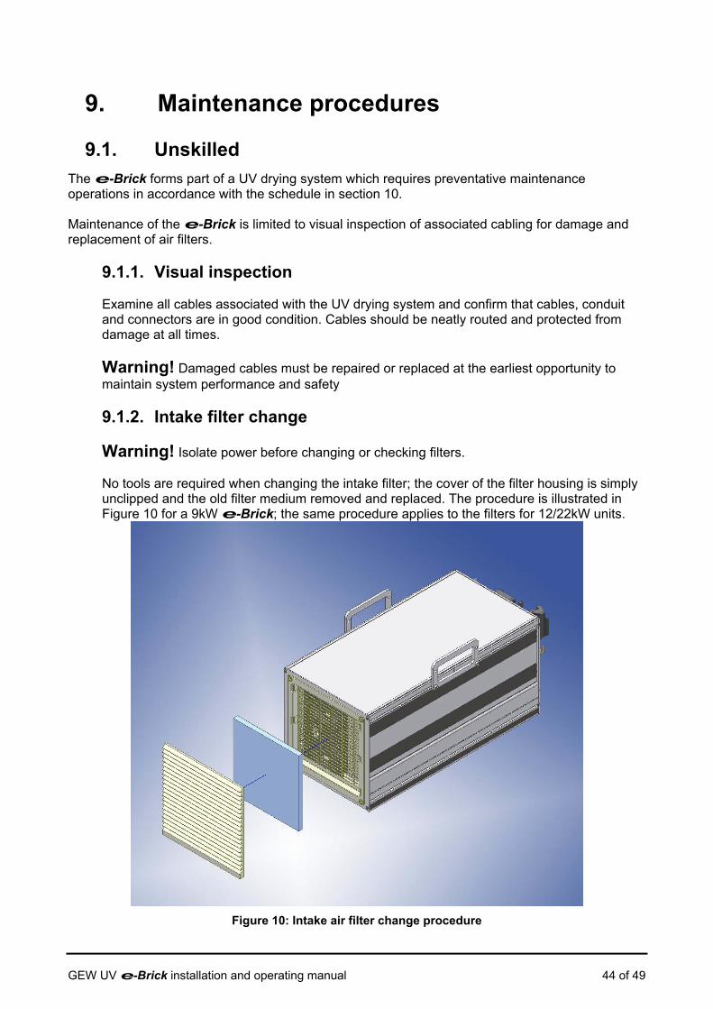
9.1. Unskilled The e-Brick forms part of a UV drying system which requires preventative maintenance operations in accordance with the schedule in section 10. Maintenance of the e-Brick is limited to visual inspection of associated cabling for damage and replacement of air filters.
9.1.1. Visual inspection
Examine all cables associated with the UV drying system and confirm that cables, conduit and connectors are in good condition. Cables should be neatly routed and protected from damage at all times.
Warning! Damaged cables must be repaired or replaced at the earliest opportunity to maintain system performance and safety
9.1.2. Intake filter change
Warning! Isolate power before changing or checking filters. No tools are required when changing the intake filter; the cover of the filter housing is simply unclipped and the old filter medium removed and replaced. The procedure is illustrated in Figure 10 for a 9kW e-Brick; the same procedure applies to the filters for 12/22kW units.
Figure 10: Intake air filter change procedure
GEW UV e-Brick installation and operating manual 44 of 49

9.1.3. Exhaust filter change Warning! Isolate power before changing or checking filters. A coarse filter medium is used in the exhaust port; this is unlikely to need changing unless it is contaminated in some way. The procedure is illustrated in Figure 11 for the 9kW and 12kW products. A similar procedure is followed for the two rectangular exhaust filters on the 22kW e-Brick.
Figure 11: Exhaust air filter change procedure
9.2. Skilled All other maintenance operations are considered skilled and shall be carried out by GEW service technicians or engineering personnel.
GEW UV e-Brick installation and operating manual 45 of 49

10. UV System Maintenance Schedule
Advice! To ensure consistent performance, GEW UV drying systems should be inspected at the intervals shown in the following schedule; more frequent checks may be necessary depending on operating conditions. Evidence of carrying out recommended maintenance procedures is required to validate claims under the GEW warranty (a suitable template is available from GEW for use by customers).
Maintenance Item Check
Clean
Replace
Frequency (hours)
General Drain air regulator (pneumatic shutters only) X 40 Straighten flexiduct X 40 Check air filters on Lamphead / Heatsink / Cabinet grilles & apertures X 500 Check reflector cassette for dust build-up X 500 Check and replace all air inlet filter media X X 1000 Check integrity of all cables, connectors and ducting X 1000 Check all connectors for evidence of contact wear or damage X 2000 UV Lamp Remove lamp chassis from lamphead, clean as required:
• Cold filter (where fitted) • UV lamp & reflector (use Isopropyl alcohol) • Heat sink base & shutter
X X X X
100
Check drying performance, replace UV lamp if necessary ** X X 1,000 ** When fitting a new lamp, examine the dichroic reflector (if fitted) and arrange for renewal if required.
X X 4000
Check cables to lamp/terminals X 2000 Lubricate shutter pivots (PTFE/silicone lubricant) X X 2000 Powerbrick and HV upright cabinets Clean or replace cabinet filter X X X 500 Clean out dust X 500 Check terminals, tighten if necessary; report any terminal damage X 4000 Check cabinet cooling fan X 4000 e-Brick Check filters X 40 Clean or replace intake and exhaust filters X X 500 If necessary, wipe down exterior surfaces of enclosure with a lint free cloth slightly dampened with water or Isopropyl Alcoho (lPA).
X 500
System cooling fan & Ozone filter (where applicable) Check duct inlet X 40 Check for vibration X 4000 Inspect Ozone filter; replace filter panels when the granules (coloured purple when new) have turned brown.
X X 4000
Water Chiller (where fitted) Drain and refill using the recommended amount of anticorrosion additive; see chiller manual for specific details.
X X 5000
GEW UV e-Brick installation and operating manual 46 of 49
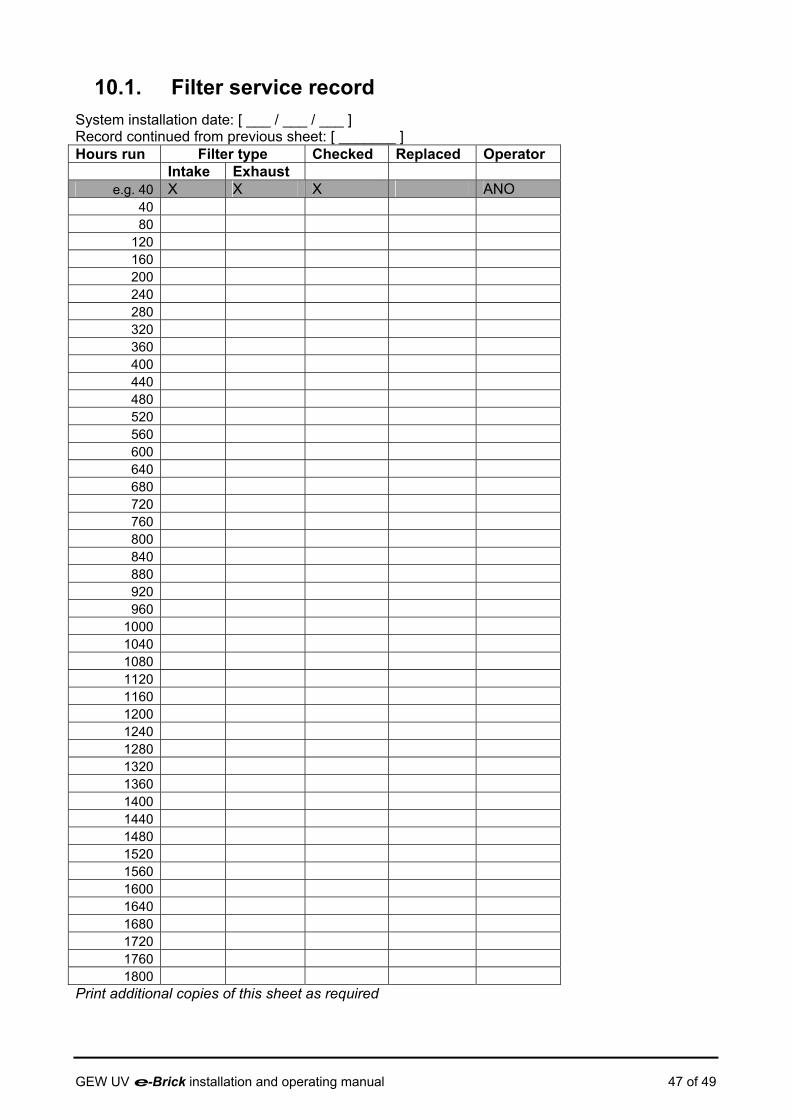
10.1. Filter service record System installation date: [ ___ / ___ / ___ ] Record continued from previous sheet: [ _______ ] Hours run Filter type Checked Replaced Operator
Intake Exhaust e.g. 40 X X X ANO
40 80
120 160 200 240 280 320 360 400 440 480 520 560 600 640 680 720 760 800 840 880 920 960
1000 1040 1080 1120 1160 1200 1240 1280 1320 1360 1400 1440 1480 1520 1560 1600 1640 1680 1720 1760 1800
Print additional copies of this sheet as required
GEW UV e-Brick installation and operating manual 47 of 49

11. Product Warranty Statement
11.1. General GEW products are manufactured to the highest standards of mechanical and electrical reliability. We support all our products with a comprehensive warranty. We treat all warranty issues seriously and will respond promptly to their resolution.
11.2. Installation and Commissioning It is essential that products are installed and commissioned correctly. Warranty is valid only when an installation is performed by:
• GEW engineers themselves • An engineer from an approved GEW agent or distributor • A certified GEW installer
Please check with GEW if you have any doubts about who is installing your system.
11.3. Warranty Validation Certificate ( WVC ) Each new system once commissioned is issued with a WVC, this is dated and validates the warranty start date and system specific details. Until this certificate is issued the warranty is not activated. The warranty applies to the specific system at a specific location. It is not transferable to other locations.
11.4. Warranty terms The following applies unless different terms and conditions of warranty have been agreed and confirmed in writing.
Included: a) All new products are covered by a 12 month parts and labour warranty from the date on the
WVC. b) Faulty parts will be replaced without charge c) Full technical support and help from our service hotline.
Excluded: a) Curing performance of the equipment (unless agreed in writing in advance). b) Products installed by unapproved personnel c) Products modified or adjusted in any way. d) Products moved or relocated to other locations after issue of the original WVC. e) Parts subject to fair wear and tear. f) All glass components g) Damage to power supplies and control by the use of non GEW spare lamps. h) Damage caused by products not maintained according to our instruction manual. i) Any consequential loss howsoever caused.
GEW UV e-Brick installation and operating manual 48 of 49
GEW UV e-Brick installation and operating manual 49 of 49
11.5. Making a Claim In the event of a problem becoming apparent contact the company who supplied the product, with a description of your claim. They will either deal with the problem themselves or contact GEW for assistance. In either event, if you do not get a prompt response, please contact us and we will help.
11.6. Purchase of spare parts All spare parts are subject to a 12 month return to base warranty, this applies only to the part itself. GEW keeps thousands of parts on stock to ensure a fast efficient response to any request for a spare part. We will ship any part to any destination. For identification of parts refer to the CD with your system. Our web site has more information www.gewuv.com GEW are dedicated to helping customers operate their systems at the lowest possible cost. We offer discounts on lamps, parts and service rates.

GEW UV DRYING SYSTEM
e-Brick (EC)
TOUCHSCREEN (TS8006 / EC) SOFTWARE OPERATING MANUAL
…engineering UV
GEW (EC) Limited Kings Mill Lane, South Nutfield
REDHILL, Surrey RH1 5NB, England
Telephone: +44 (0)1737 824500 Fax: +44 (0)1737 823822
Spares & Service telephone: +44 (0)1737 824510
www.gewuv.com
GEW UV e-Brick HMI software operating manual 1 of 18
Table of Contents
1. Scope......................................................................................................................................... 4 2. Product Description ................................................................................................................... 4
2.1. Related documentation....................................................................................................... 4 2.1.1. GEW Product manuals................................................................................................ 4 2.1.2. European (EN) Standards ........................................................................................... 4
3. Human Machine Interface.......................................................................................................... 5 3.1. Firmware update................................................................................................................. 5 3.2. Safety features ................................................................................................................... 5 3.3. Output power curve for e-Brick system ............................................................................ 5 3.4. Using the HMI..................................................................................................................... 7
3.4.1. Starting up the UV system........................................................................................... 7 3.4.2. Selecting lamps ........................................................................................................... 9 3.4.3. Setting power levels .................................................................................................... 9 3.4.4. Switching off .............................................................................................................. 10 3.4.5. Configuration, Shutter test, Lamp change function ................................................... 11 3.4.6. Production profiles..................................................................................................... 11 3.4.7. Consumable parts ..................................................................................................... 12 3.4.8. GEW Warranty .......................................................................................................... 12
3.5. Fault finding guidelines..................................................................................................... 13 3.5.1. Warning indicators..................................................................................................... 14 3.5.2. General faults ............................................................................................................ 14 3.5.3. Individual faults.......................................................................................................... 15
3.6. HMI Flow chart ................................................................................................................. 18
Figures Figure 1: Lamp output power curve .................................................................................................. 5
GEW UV e-Brick HMI software operating manual 2 of 18
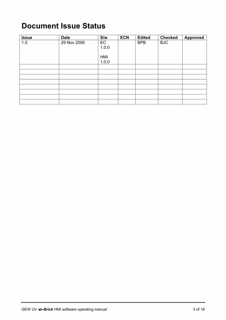
Document Issue Status Issue Date S/w ECN Edited Checked Approved 1.0 29 Nov 2006 EC
1.0.0 HMI 1.0.0
BPB BJC
GEW UV e-Brick HMI software operating manual 3 of 18
1. Scope This document describes the user interface for the e-Brick with a GEW TS8006 Colour LCD TouchScreen.
2. Product Description The UV drying systems manufactured by GEW (EC) Limited are designed for the instantaneous drying of inks, varnishes and adhesives that are sensitive to ultra violet (UV) light. A typical web colour printing press comprises several printing stations in line, each station applying ink of a different colour. The ink printed on the first station must be thoroughly dry before entering the second station to avoid contaminating the press. A drying unit containing a high power UV lamp is located between print stations. The web passes through a ‘web slot' in the drier and travels past the lamp. UV drying is effectively instantaneous, allowing the press to be run at high speed. An extra drying unit may be located at the end of the web for drying varnish applied after the final printing. The e-Brick is a highly integrated power supply designed specifically for powering UV lamps in drying systems. The e-Brick features integrated controls and all necessary hardware to control the UV system including lamp cooling, safety interlock features, and a press interface allowing the UV curing to be controlled automatically. The e-Brick power supply is a component part of a GEW UV drying system. A complete system would also include GEW UV dryer(s) e.g. VCP, custom cabling, fan cooling, ducting and a human machine interface (HMI) to control the operation of the system. Systems vary in complexity and the scope of supply differs depending on the application; all systems require commissioning by trained personnel. This manual should be referred to alongside the user manuals and installation information for the other components in the system.
2.1. Related documentation 2.1.1. GEW Product manuals
Document Title VCP user manual ECP user manual NUVA+ user manual TouchScreen HMI Software manual
2.1.2. European (EN) Standards
Standard Title EN12100-1:2003 Safety of Machinery – Basic terminology, methodology EN12100-2:2003 Safety of Machinery – Technical principles EN1050:1997 Safety of Machinery – Principles of risk assessment EN954-1:1997 Safety of Machinery – Safety related parts of control
systems EN60204-1:1998 Safety of Machinery – Electrical equipment of machines
GEW UV e-Brick HMI software operating manual 4 of 18

3. Human Machine Interface The e-Brick Human Machine Interface (HMI) has been designed for maximum ease of use. A single HMI screen enables monitoring and controlling of up to 16 lamps in a system. For a graphical overview of the HMI structure, please refer to section 3.6.
3.1. Firmware update GEW service technicians may update the embedded software in an e-Brick system using a PC with suitable software and a standard USB cable.
3.2. Safety features The HMI forms part of the safety features of the e-Brick UV drying system and should only be operated by suitably trained personnel. Advice! If any safety feature is compromised or failure suspected, always refer to GEW for service.
3.3. Output power curve for e-Brick system Lamp Power
Max power Set point adjustable
Min Power Stand by power
Press on speed Auto power
0Vdc Press speed 10Vdc
Figure 1: Lamp output power curve
The lamp output power is adjusted by 4 parameters: Max power (0-100%) This sets the maximum power supported by the lamp. The value is a % of the maximum power output of the e-Brick. For a 9kW e-Brick, a value of 80% limits the maximum power to 7.2kW. GEW UV e-Brick HMI software operating manual 5 of 18
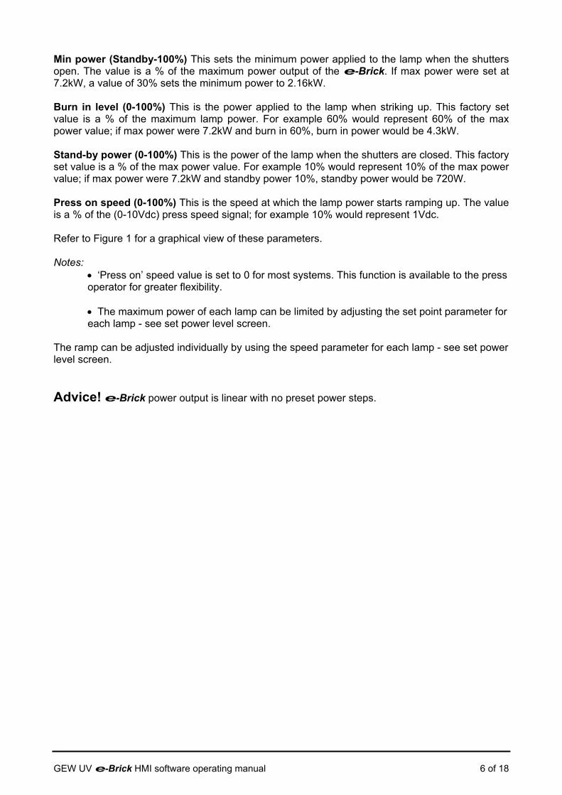
Min power (Standby-100%) This sets the minimum power applied to the lamp when the shutters open. The value is a % of the maximum power output of the e-Brick. If max power were set at 7.2kW, a value of 30% sets the minimum power to 2.16kW. Burn in level (0-100%) This is the power applied to the lamp when striking up. This factory set value is a % of the maximum lamp power. For example 60% would represent 60% of the max power value; if max power were 7.2kW and burn in 60%, burn in power would be 4.3kW. Stand-by power (0-100%) This is the power of the lamp when the shutters are closed. This factory set value is a % of the max power value. For example 10% would represent 10% of the max power value; if max power were 7.2kW and standby power 10%, standby power would be 720W. Press on speed (0-100%) This is the speed at which the lamp power starts ramping up. The value is a % of the (0-10Vdc) press speed signal; for example 10% would represent 1Vdc. Refer to Figure 1 for a graphical view of these parameters. Notes:
• ‘Press on’ speed value is set to 0 for most systems. This function is available to the press operator for greater flexibility. • The maximum power of each lamp can be limited by adjusting the set point parameter for each lamp - see set power level screen.
The ramp can be adjusted individually by using the speed parameter for each lamp - see set power level screen. Advice! e-Brick power output is linear with no preset power steps.
GEW UV e-Brick HMI software operating manual 6 of 18

3.4. Using the HMI 3.4.1. Starting up the UV system
Initialisation
When switching on the printing machine, the operator should: • Ensure three-phase (or, if applicable, single phase) supply is available. • Switch on the mains isolators for each e-Brick or print station cabinet. • Most e-Brick systems will have electric shutters but, for dryers with pneumatic shutters, switch on the compressed air supply. After initialising (30s delay), the touch screen should display the GEW logo. Press anywhere on the logo to display lamp information:
The first column indicates lamp selection:
• transparent = lamp deselected • solid green = lamp selected
The second column indicates the detected lamp type
• UV lamp cassette • IR lamp cassette
The third column is a bargraph display of the lamp power (%) and current status.
• transparent = lamp off • flashing yellow = burn in (Voltage) • flashing amber = burn in (temperature) • flashing green = ready with shutter closed • solid green = lamp on with shutter opened • solid blue = cooling • solid red = faulty lamp
Select lamps Select the required lamps, or accept the existing selection, as described in 3.4.2.
Preset power levels Preset the power levels of the selected lamps globally, or individually, as
described in 3.4.3.
Lamp hours
Lamp hours for each lamp are displayed by pressing the [H] icon on the lamp information screens. Two hour counts are maintained: total system hours run and a resettable hour count for each lamp. The hours run can be reset by pressing the hours figure. A message “reset lamp hour” will then appear as shown. The operator has to confirm by pressing “Y” to clear the figure. Press “N” to cancel.
Status and % Power
Selection Lamp type (UV or IR)
GEW UV e-Brick HMI software operating manual 7 of 18

Start the lamps
When the required lamps have been selected, and their power levels have been
preset, press the green button to start them. The exhaust fans will start up and a coloured bar will be displayed for each lamp; the colour of the bars is significant:
• transparent = lamp off • flashing yellow = burn in (Voltage) • flashing amber = burn in (temperature) • flashing green = ready with shutter closed • solid green = lamp on with shutter opened • solid blue = cooling • solid red = faulty lamp
Start running Start the printing machine, the lamp shutters will open and lamp power will be controlled in accordance with the preset parameters.
Monitor the lamps
To monitor the state of all lamps on a single screen, touch the ‘1 to 16’ icon to display the monitor screen:
The screen shows a numbered icon for each available lamp; the colour of the icons is significant. The first column indicates lamp selection:
• transparent = lamp deselected • solid green = lamp selected
The second column indicates the detected lamp type
• UV lamp cassette • IR lamp cassette
The third column displays the lamp power (%) and current status:
• transparent = lamp off • flashing yellow = burn in (voltage) • flashing amber = burn in (temperature) • flashing green = ready with shutter closed • solid green = lamp on with shutter opened • solid blue = cooling • solid red = faulty lamp
To return to the lamp-selection screen, touch or ‘1 to 8’ on the monitor
screen. Note that the button will turn off all the lamps.
Screen Saver To prolong the life of the LCD screen and backlight, the HMI will display a ‘Screen Saver’ message if it is not touched for ten minutes and, shortly afterwards, a blank screen. Touching the screen, or any key, will restore the display immediately.
Selection Lamp type (UV or IR)
Status and % Power
GEW UV e-Brick HMI software operating manual 8 of 18
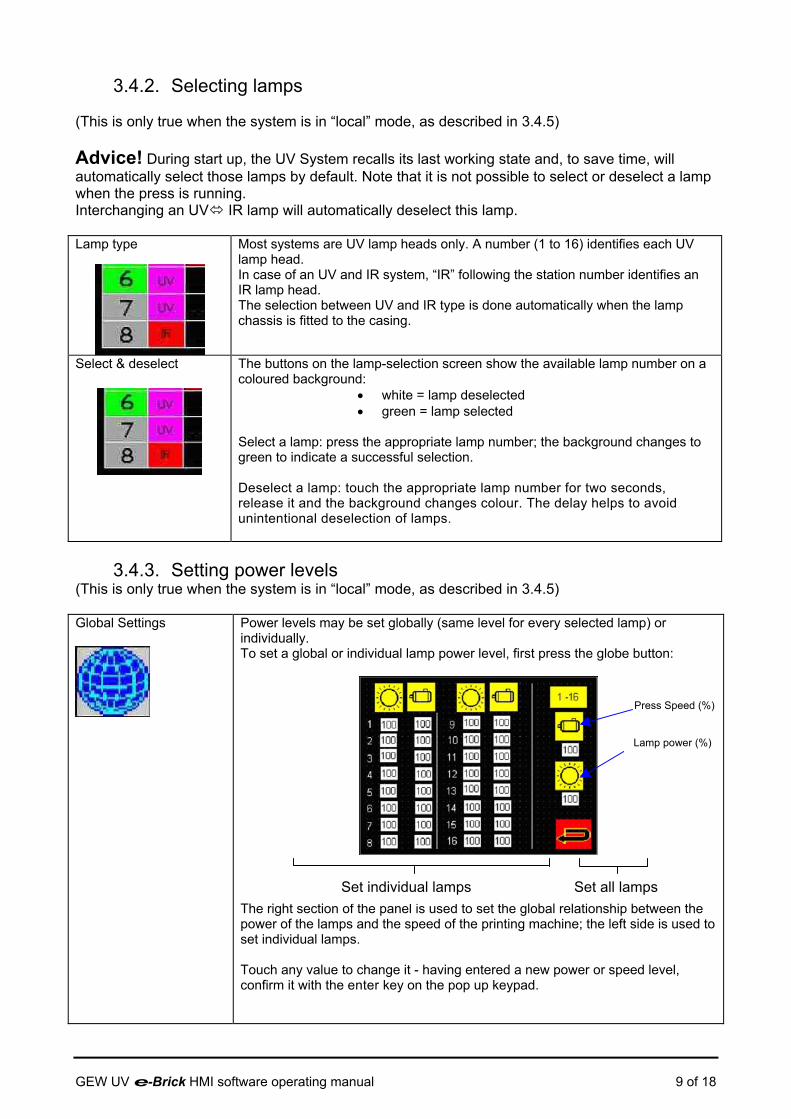
3.4.2. Selecting lamps (This is only true when the system is in “local” mode, as described in 3.4.5) Advice! During start up, the UV System recalls its last working state and, to save time, will automatically select those lamps by default. Note that it is not possible to select or deselect a lamp when the press is running. Interchanging an UV IR lamp will automatically deselect this lamp. Lamp type
Most systems are UV lamp heads only. A number (1 to 16) identifies each UV lamp head. In case of an UV and IR system, “IR” following the station number identifies an IR lamp head. The selection between UV and IR type is done automatically when the lamp chassis is fitted to the casing.
Select & deselect
The buttons on the lamp-selection screen show the available lamp number on a coloured background:
• white = lamp deselected • green = lamp selected
Select a lamp: press the appropriate lamp number; the background changes to green to indicate a successful selection. Deselect a lamp: touch the appropriate lamp number for two seconds, release it and the background changes colour. The delay helps to avoid unintentional deselection of lamps.
3.4.3. Setting power levels
(This is only true when the system is in “local” mode, as described in 3.4.5) Global Settings
Power levels may be set globally (same level for every selected lamp) or individually. To set a global or individual lamp power level, first press the globe button:
The right section of the panel is used to set the global relationship between the power of the lamps and the speed of the printing machine; the left side is used to set individual lamps. Touch any value to change it - having entered a new power or speed level, confirm it with the enter key on the pop up keypad.
Set individual lamps Set all lamps
Press Speed (%)
Lamp power (%)
GEW UV e-Brick HMI software operating manual 9 of 18
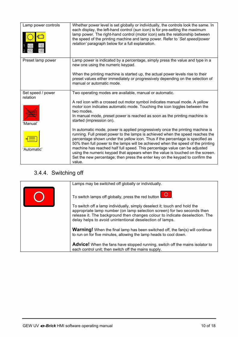
Lamp power controls
Whether power level is set globally or individually, the controls look the same. In each display, the left-hand control (sun icon) is for pre-setting the maximum lamp power. The right-hand control (motor icon) sets the relationship between the speed of the printing machine and lamp power. Refer to ‘Set speed/power relation’ paragraph below for a full explanation.
Preset lamp power Lamp power is indicated by a percentage, simply press the value and type in a new one using the numeric keypad. When the printing machine is started up, the actual power levels rise to their preset values either immediately or progressively depending on the selection of manual or automatic mode.
Set speed / power relation
‘Manual’
‘Automatic’
Two operating modes are available, manual or automatic. A red icon with a crossed out motor symbol indicates manual mode. A yellow motor icon indicates automatic mode. Touching the icon toggles between the two modes. In manual mode, preset power is reached as soon as the printing machine is started (impression on). In automatic mode, power is applied progressively once the printing machine is running. Full preset power to the lamps is achieved when the speed reaches the percentage shown under the yellow icon. Thus if the percentage is specified as 50% then full power to the lamps will be achieved when the speed of the printing machine has reached half full speed. This percentage value can be adjusted using the numeric keypad that appears when the value is touched on the screen. Set the new percentage; then press the enter key on the keypad to confirm the value.
3.4.4. Switching off
Lamps may be switched off globally or individually.
To switch lamps off globally, press the red button . To switch off a lamp individually, simply deselect it; touch and hold the appropriate lamp number (on lamp selection screen) for two seconds then release it. The background then changes colour to indicate deselection. The delay helps to avoid unintentional deselection of lamps. Warning! When the final lamp has been switched off, the fan(s) will continue to run on for five minutes, allowing the lamp heads to cool down. Advice! When the fans have stopped running, switch off the mains isolator to each control unit; then switch off the mains supply.
GEW UV e-Brick HMI software operating manual 10 of 18

3.4.5. Configuration, Shutter test, Lamp change function
Customer access to: Production Profiles, Consumable parts list for system and GEW Warranty validation screens Service technician access to: Configuration and Commissioning screens Shutter multi-function key (to left of touch screen)
Four symbols are displayed under the index page:
a. This icon displays the impression status. b. This icon shows the shutter status (shutter
symbol changes from open to closed). c. This button toggles between “local” and
“remote” mode. In local, the GEW screen drives the system, while in “remote” it is the manufacturer screen that controls the system; this feature may not be available on all systems.
d. These icons show the press interface ‘Ready’ and ‘Fault’ signal status; Speed shows the current (0-10V) press speed signal as a percentage.
Shutter multi-function key This key performs two functions. When the system is not running this key will open (close) all shutters. If the system is running this button operates the shutter of all de-selected lamps, allowing a quick change of lamp without stopping the press.
a c
b d
3.4.6. Production profiles
This screen is used to store and retrieve up to 10 production profiles.
- The operator can create and select profiles - Lamp power and auto power ramp settings
are listed for each station - Profiles can be downloaded or uploaded to /
from the UV system Upload Download Select stored/create new profile Save profile
GEW UV e-Brick HMI software operating manual 11 of 18
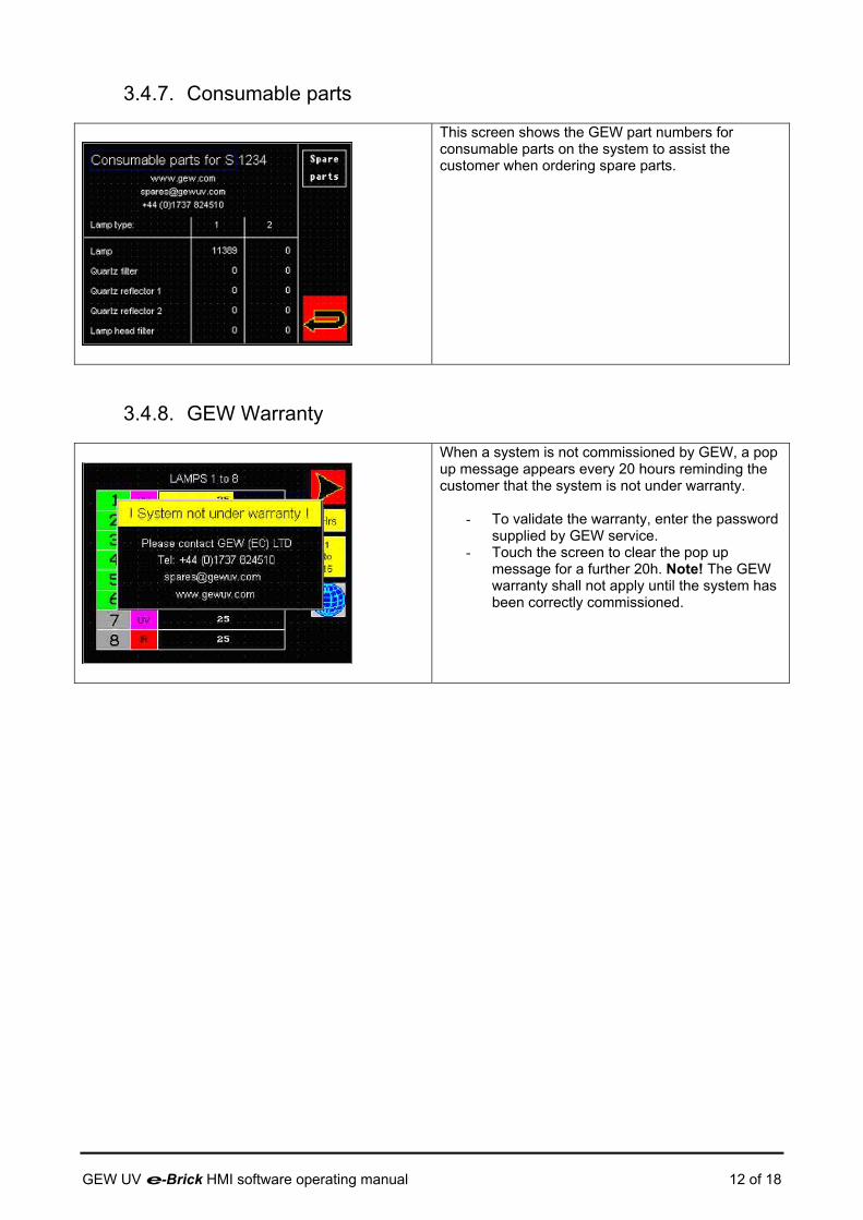
3.4.7. Consumable parts
This screen shows the GEW part numbers for consumable parts on the system to assist the customer when ordering spare parts.
3.4.8. GEW Warranty
When a system is not commissioned by GEW, a pop up message appears every 20 hours reminding the customer that the system is not under warranty.
- To validate the warranty, enter the password supplied by GEW service.
- Touch the screen to clear the pop up message for a further 20h. Note! The GEW warranty shall not apply until the system has been correctly commissioned.
GEW UV e-Brick HMI software operating manual 12 of 18
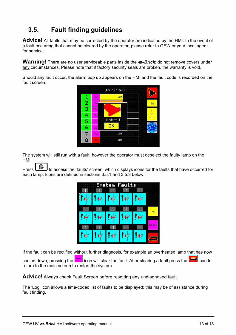
3.5. Fault finding guidelines Advice! All faults that may be corrected by the operator are indicated by the HMI. In the event of a fault occurring that cannot be cleared by the operator, please refer to GEW or your local agent for service. Warning! There are no user serviceable parts inside the e-Brick; do not remove covers under any circumstances. Please note that if factory security seals are broken, the warranty is void. Should any fault occur, the alarm pop up appears on the HMI and the fault code is recorded on the fault screen.
The system will still run with a fault, however the operator must deselect the faulty lamp on the HMI.
Press to access the ‘faults’ screen, which displays icons for the faults that have occurred for each lamp. Icons are defined in sections 3.5.1 and 3.5.3 below.
If the fault can be rectified without further diagnosis, for example an overheated lamp that has now
cooled down, pressing the icon will clear the fault. After clearing a fault press the icon to return to the main screen to restart the system. Advice! Always check Fault Screen before resetting any undiagnosed fault. The ‘Log’ icon allows a time-coded list of faults to be displayed; this may be of assistance during fault finding.
GEW UV e-Brick HMI software operating manual 13 of 18

3.5.1. Warning indicators The e-Brick has three indicator LEDs, one for the internal 24V supply status, a second to show the main contactor (K1) status, and a third to indicate fault status. If the K1 LED fails to light when the lamp is selected and no other fault is present, please refer to GEW for service support.
3.5.2. General faults
Water cooling unit (chiller) failure The cooling unit has failed while the printing machine is running.
• Check chiller MCB and reset if necessary • Ensure that the chiller is switched on • The chiller may have developed a fault; check the control panel to see if a fault is reported • Refer to the chiller manual for further fault finding suggestions
Emergency stop failure The operator may have triggered an emergency stop of the printing machine
• Check external emergency stop (e-stop) circuitry and switches • Check panel circuit breakers in external equipment • Check e-stop links between e-Brick units are intact (communications cables linking master-slave / slave/slave carry the e-Brick e-stop links)
Fan failure The fan fails to operate when a lamp is started. • Check the electrical supply to the fan • Check the MCB supplying power to the fan, reset if necessary • Check the thermal overload device on the fan. If the switch has been tripped, reset it
by pressing “1” button on the switch housing, then reset the fault on the touch screen On systems where an external air handling unit is used in place of the GEW system fan, this fault may show if the cooling air pressure does not reach a predetermined threshold within 90s of starting the cooling system
System Safety Switch
• Check the functionality of the system safety switch • Check integrity of wiring and connectors for the system safety switch
GEW UV e-Brick HMI software operating manual 14 of 18
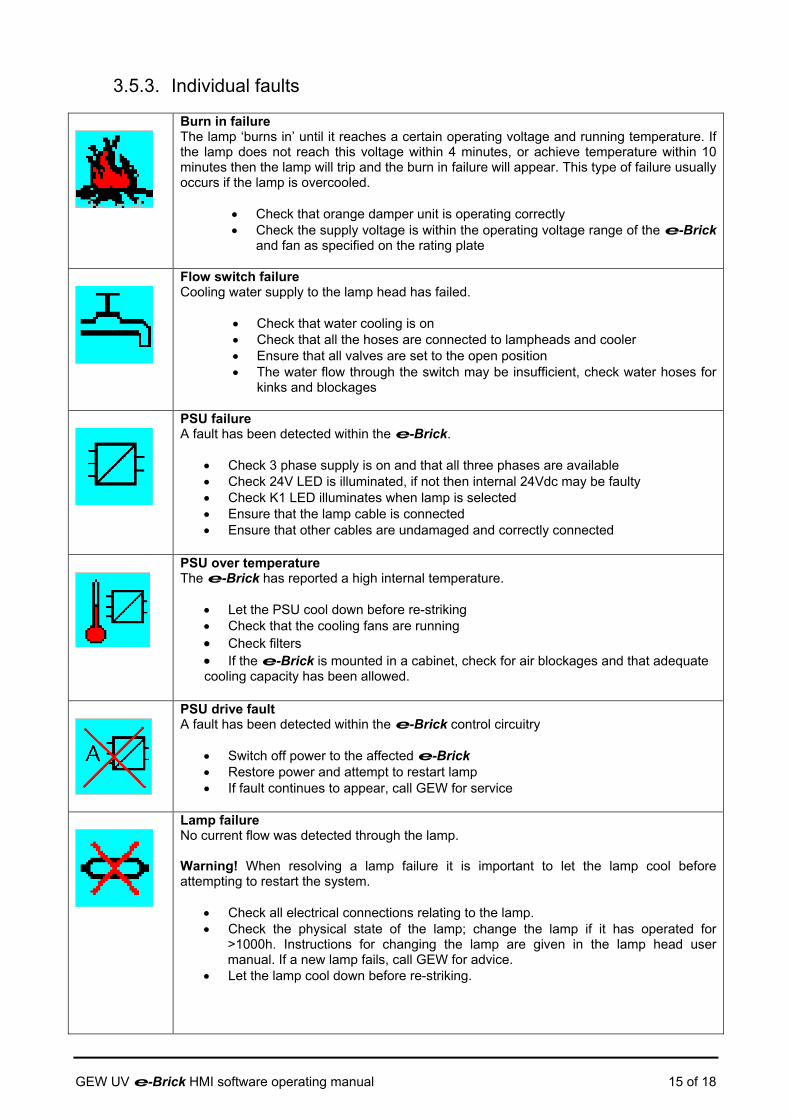
3.5.3. Individual faults
Burn in failure The lamp ‘burns in’ until it reaches a certain operating voltage and running temperature. If the lamp does not reach this voltage within 4 minutes, or achieve temperature within 10 minutes then the lamp will trip and the burn in failure will appear. This type of failure usually occurs if the lamp is overcooled.
• Check that orange damper unit is operating correctly • Check the supply voltage is within the operating voltage range of the e-Brick
and fan as specified on the rating plate
Flow switch failure Cooling water supply to the lamp head has failed.
• Check that water cooling is on • Check that all the hoses are connected to lampheads and cooler • Ensure that all valves are set to the open position • The water flow through the switch may be insufficient, check water hoses for
kinks and blockages
PSU failure A fault has been detected within the e-Brick.
• Check 3 phase supply is on and that all three phases are available • Check 24V LED is illuminated, if not then internal 24Vdc may be faulty • Check K1 LED illuminates when lamp is selected • Ensure that the lamp cable is connected • Ensure that other cables are undamaged and correctly connected
PSU over temperature The e-Brick has reported a high internal temperature.
• Let the PSU cool down before re-striking • Check that the cooling fans are running • Check filters • If the e-Brick is mounted in a cabinet, check for air blockages and that adequate cooling capacity has been allowed.
PSU drive fault A fault has been detected within the e-Brick control circuitry
• Switch off power to the affected e-Brick • Restore power and attempt to restart lamp • If fault continues to appear, call GEW for service
Lamp failure No current flow was detected through the lamp. Warning! When resolving a lamp failure it is important to let the lamp cool before attempting to restart the system.
• Check all electrical connections relating to the lamp. • Check the physical state of the lamp; change the lamp if it has operated for
>1000h. Instructions for changing the lamp are given in the lamp head user manual. If a new lamp fails, call GEW for advice.
• Let the lamp cool down before re-striking.
GEW UV e-Brick HMI software operating manual 15 of 18

Safety switch failure On systems with lamp heads mounted on hinged brackets, this alarm will indicate that the lamp head has been hinged open.
• Check that the lamp is firmly seated in the outer casing • Check that the lamp head is closed (hinged head) • If this fault occurs with the lamp head hinged closed then check the alignment of
the interlock arm with the interlock switch at the front of the lamp head.
Lamp over temperature The lamp head overheats. Overheating may be caused by problems in the lamp head. Advice! Let the lamp cool down before re-striking.
• Check that the fan is running and that its rotation is correct • Check that the damper operates normally, check for air blockage • Check flexible ducting for obstructions • Check electrical connections between the e-Brick and the lamp head • Check the lamp chassis is fully inserted in the lamp head; ensure that the plug to
the lamp head is fully engaged
Shutter failure Shutter failure while the printing machine is running.
• Check electrical connections between the e-Brick and the lamp head • Check the shutter mechanism for ink build-up. If necessary, clean with isopropyl
alcohol • Check micro switches • Check for mechanical jam
A Shutter test can be performed while the lamps are off but selected on the HMI:
Press the shutter test icon to the left of the HMI. This will drive the shutter to the fully open position. Press the icon once more to close the shutters. If a fault occurs, it will be displayed on the fault screen. Electric shutter test
• Press the shutter test icon. Check that shutters open, check that open switch is activated
• Press the shutter test icon. Check that shutters close, check that close switch is activated
Pneumatic shutter test
• Press the shutter test icon. A hiss of air should be heard with the selected lamps, the shutters should then click open and remain open. Check that shutters open and that the micro switch is released.
• Press the shutter test icon. A hiss of air should be heard with the selected lamps, the shutters should then close. Check shutters position and that the micro switch is activated.
• Check inside the interface box to confirm that the tubes carrying compressed air to the lamp head are intact.
Damper Failure A fault (warning) is logged if the damper cable is not connected or the damper is more than 10% out from the requested position for more than 30 seconds.
• Check electrical connections between the e-Brick and the damper • Check that the damper operates normally, check for air blockage • Check flexible ducting for obstructions
Note! The system will still run with this warning present
GEW UV e-Brick HMI software operating manual 16 of 18
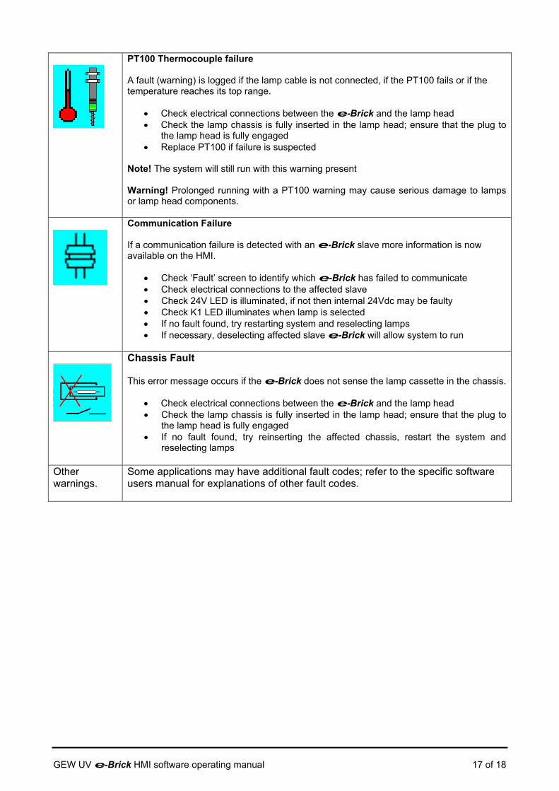
PT100 Thermocouple failure A fault (warning) is logged if the lamp cable is not connected, if the PT100 fails or if the temperature reaches its top range.
• Check electrical connections between the e-Brick and the lamp head • Check the lamp chassis is fully inserted in the lamp head; ensure that the plug to
the lamp head is fully engaged • Replace PT100 if failure is suspected
Note! The system will still run with this warning present Warning! Prolonged running with a PT100 warning may cause serious damage to lamps or lamp head components.
Communication Failure If a communication failure is detected with an e-Brick slave more information is now available on the HMI.
• Check ‘Fault’ screen to identify which e-Brick has failed to communicate • Check electrical connections to the affected slave • Check 24V LED is illuminated, if not then internal 24Vdc may be faulty • Check K1 LED illuminates when lamp is selected • If no fault found, try restarting system and reselecting lamps • If necessary, deselecting affected slave e-Brick will allow system to run
Chassis Fault This error message occurs if the e-Brick does not sense the lamp cassette in the chassis.
• Check electrical connections between the e-Brick and the lamp head • Check the lamp chassis is fully inserted in the lamp head; ensure that the plug to
the lamp head is fully engaged • If no fault found, try reinserting the affected chassis, restart the system and
reselecting lamps
Other warnings.
Some applications may have additional fault codes; refer to the specific software users manual for explanations of other fault codes.
GEW UV e-Brick HMI software operating manual 17 of 18

GEW UV e-Brick HMI software operating manual 18 of 18
3.6. HMI Flow chart General operation screens: Start up screen: Main operator screen:
Global screen:
Configuration menu: Alarm screen:
Start Stop Shutter Multi-key
Production profiles: Consumable parts: Validate warranty:

REPLACING THE UV LAMP
e-Systems This chapter explains how to fit a new UV lamp, including the removal and disposal of the
old UV lamp.
TOOLS
Set of hexagon allen keys and an 8mm socket required.
PREPARATION Deselect the required lamp number on the touch screen for the lamp you wish to change.
Allow the lamp to cool down and press the lamp change button on the touch screen so this
turns red.
This will open the shutter on all deselected lamps
GEW UV system operating manual Issue 1.00 –Sept 2005 E-systems Lamp Change - page 1 of 4
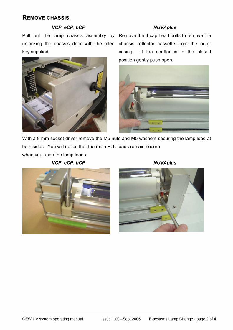
REMOVE CHASSIS VCP, eCP, hCP NUVAplus
Pull out the lamp chassis assembly by
unlocking the chassis door with the allen
key supplied.
Remove the 4 cap head bolts to remove the
chassis reflector cassette from the outer
casing. If the shutter is in the closed
position gently push open.
With a 8 mm socket driver remove the M5 nuts and M5 washers securing the lamp lead at
both sides. You will notice that the main H.T. leads remain secure
when you undo the lamp leads.
VCP, eCP, hCP NUVAplus
GEW UV system operating manual Issue 1.00 –Sept 2005 E-systems Lamp Change - page 2 of 4
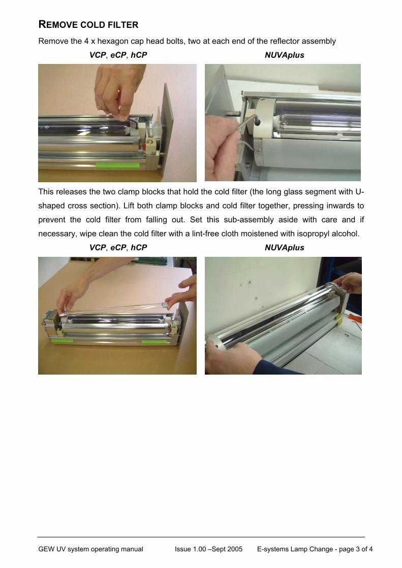
REMOVE COLD FILTER Remove the 4 x hexagon cap head bolts, two at each end of the reflector assembly
VCP, eCP, hCP NUVAplus
This releases the two clamp blocks that hold the cold filter (the long glass segment with U-
shaped cross section). Lift both clamp blocks and cold filter together, pressing inwards to
prevent the cold filter from falling out. Set this sub-assembly aside with care and if
necessary, wipe clean the cold filter with a lint-free cloth moistened with isopropyl alcohol.
VCP, eCP, hCP NUVAplus
GEW UV system operating manual Issue 1.00 –Sept 2005 E-systems Lamp Change - page 3 of 4

REMOVE OLD LAMP Holding the lamp by the ends the lamp can now be lifted out.
VCP, eCP, hCP NUVAplus
Ensure safe disposal of the old lamp.
CLEAN REFLECTOR The reflector assembly can be cleaned whilst the lamp is removed. Clean with a soft cloth
dampened with isopropyl alcohol (IPA).
FIT NEW LAMP Replacing a lamp is a reversal of the procedure above.
Unwrap a new lamp from its container, holding it by its ceramic end caps. Fit the lamp
carefully into the reflector assembly. The lamp has a slender neck at each end; take
particular care not to knock the lamp. If you touch the surface of the UV lamp, clean the
area with the wipe provided with the replacement lamp.
Ensuring an unobstructed path, refit the lamp cables, replace the cold filter and clamp
block sub-assembly, securing it with the 4 x hexagonal cap-head bolts. Before fully
tightening, check the lamp for freedom of movement, it should have a loose fit when the
screws are tight.
Insert the lamp chassis assembly into the lamphead body and re-tighten the locking
assembly.
GEW UV system operating manual Issue 1.00 –Sept 2005 E-systems Lamp Change - page 4 of 4