E-BAM PLUS PARTICULATE MONITOR OPERATION MANUAL · E-BAM PLUS-9800 Rev C Page 7 1.4 Beta Radiation...
83
Met One Instruments, Inc. 1600 NW Washington Blvd. Grants Pass, OR 97526 Telephone: (541) 471-7111 Facsimile: (541) 471-7116 www.metone.com E-BAM PLUS Particulate Monitor Operation Manual - © Copyright 2016 Met One Instruments, Inc. All Rights Reserved worldwide. No part of this publication may be reproduced, transmitted, transcribed, stored in a retrieval system, or translated into any other language in any form without the written permission of Met One Instruments, Inc. E-BAM PLUS PARTICULATE MONITOR OPERATION MANUAL E-BAM PLUS-9800 REV C
Transcript of E-BAM PLUS PARTICULATE MONITOR OPERATION MANUAL · E-BAM PLUS-9800 Rev C Page 7 1.4 Beta Radiation...

Met One Instruments, Inc. 1600 NW Washington Blvd. Grants Pass, OR 97526 Telephone: (541) 471-7111 Facsimile: (541) 471-7116 www.metone.com
E-BAM PLUS Particulate Monitor Operation Manual - © Copyright 2016 Met One Instruments, Inc. All Rights Reserved
worldwide. No part of this publication may be reproduced, transmitted, transcribed, stored in a retrieval system, or translated into any other language in any form without the written permission of Met One Instruments, Inc.
E-BAM PLUS PARTICULATE MONITOR
OPERATION MANUAL
E-BAM PLUS-9800 REV C

Page 2 E-BAM PLUS-9800 Rev C
E-BAM PLUS-9800 Rev C Page 3
Table of Contents
1 INTRODUCTION 6 1.1 About This Manual ........................................................................................................... 6
1.2 Technical Service ............................................................................................................. 6 1.3 E-BAM PLUS: Environmental Beta Attenuation Monitor .................................................. 6 1.4 Beta Radiation Safety Statement ..................................................................................... 7 1.5 The E-BAM PLUS and U.S. EPA Equivalent Methods ..................................................... 7 1.6 E-BAM PLUS Specifications ............................................................................................ 8
2 E-BAM PLUS INSTALLATION AND COMMISSIONING 9 2.1 Unpacking ........................................................................................................................ 9 2.2 Accessories ...................................................................................................................... 9 2.3 Assembling the E-BAM PLUS ........................................................................................ 10 2.4 Electrical Connections .................................................................................................... 13
2.5 Power-up and Automatic Operation ............................................................................... 16 2.6 Power-up Settings Verification and Automatic Self-Test ................................................ 16
2.7 Configuring External Sensors ......................................................................................... 18 2.7.1 Configuring the 597 Sensor ............................................................................................ 18
2.7.2 Changing Sensor Addresses .......................................................................................... 18 2.8 Filter Tape Loading ........................................................................................................ 19 2.9 Warm-up Period ............................................................................................................. 19
3 E-BAM PLUS USER INTERFACE and MENU SYSTEM 20 3.1 The User Interface - Touchscreen Display Functions ..................................................... 20
3.2 Main Operating Screen .................................................................................................. 20 3.3 Menu Hierarchy and Navigation ..................................................................................... 22 3.4 Operate Menu ................................................................................................................ 24
3.4.1 Start Sample .................................................................................................................. 24
3.4.2 Load Filter Tape ............................................................................................................. 24 3.4.3 Transfer Data ................................................................................................................. 24 3.4.4 About .............................................................................................................................. 25
3.4.5 Prepare Shipping............................................................................................................ 25 3.5 Test Menu ...................................................................................................................... 25 3.5.1 Leak Test ....................................................................................................................... 26
3.5.2 Ambient Temperature ..................................................................................................... 26 3.5.3 Ambient Pressure ........................................................................................................... 26 3.5.4 Flow Calibration.............................................................................................................. 26 3.5.5 Self-Test ......................................................................................................................... 27 3.5.6 Parameters ..................................................................................................................... 27
3.5.7 Filter Sensors ................................................................................................................. 27 3.5.8 Span Mass Audit ............................................................................................................ 28
3.5.9 Tape Test ....................................................................................................................... 28 3.5.10 Vane/Count Test ............................................................................................................ 28 3.5.11 Analog Output Calibration .............................................................................................. 28 3.5.12 Analog Output Test ........................................................................................................ 30 3.5.13 Inlet Heater ..................................................................................................................... 30 3.5.14 Relay Test ...................................................................................................................... 31 3.5.15 Digital Link ...................................................................................................................... 31 3.6 Setup Menu .................................................................................................................... 32

Page 4 E-BAM PLUS-9800 Rev C
3.6.1 Set Clock ........................................................................................................................ 32 3.6.2 Clear Memory ................................................................................................................. 32 3.6.3 Background .................................................................................................................... 33
3.6.4 Serial Port ...................................................................................................................... 33 3.6.5 Location .......................................................................................................................... 33 3.6.6 Data Average ................................................................................................................. 34 3.6.7 Real-Time Period ........................................................................................................... 34
3.6.8 Hourly Report ................................................................................................................. 35 3.6.9 Analog Outputs............................................................................................................... 35 3.6.10 Concentration Units ........................................................................................................ 35 3.6.11 Inlet Heater ..................................................................................................................... 36 3.6.12 Tape Advance ................................................................................................................ 36
3.6.13 Password ....................................................................................................................... 36 3.6.14 Sound Volume ................................................................................................................ 37 3.6.15 Touch Calibrate .............................................................................................................. 37 3.6.16 Standard Temp............................................................................................................... 37
3.6.17 PM Inlet .......................................................................................................................... 37 3.6.18 Cloud Data ..................................................................................................................... 38
3.7 Alarms Menu .................................................................................................................. 38
4 SAMPLE SITE SELECTION 39 4.1 Site Selection Requirements .......................................................................................... 39
4.2 Fall Hazard and Security Cautions ................................................................................. 40 4.3 Confined Sampling Locations ......................................................................................... 40
4.4 Smoke and Ash Monitoring ............................................................................................ 40
5 THE E-BAM PLUS MEASUREMENT CYCLE 41 5.1 The Hourly Measurement Cycle ..................................................................................... 41
6 MAINTENANCE, ALARMS and TROUBLESHOOTING 43
6.1 Met One Suggested Periodic Maintenance .................................................................... 43 6.2 Basic Leak Check ........................................................................................................... 44 6.3 Advanced Leak Checks .................................................................................................. 46
6.3.1 Lower System Leak Test ................................................................................................ 46 6.3.2 Upper System Leak Test ................................................................................................ 47
6.3.3 Filter Tape Leak Test ..................................................................................................... 48 6.4 Background Determination (Mass Offset) ...................................................................... 49 6.5 Nozzle/Vane Cleaning .................................................................................................... 51 6.5.1 Nozzle/Vane Cleaning .................................................................................................... 51
6.5.2 Nozzle Interior Cleaning ................................................................................................. 52 6.6 Ambient Temperature Sensor Audit ............................................................................... 53
6.7 Ambient Barometric Pressure Sensor Audit ................................................................... 53 6.8 Flow Audits and Calibrations .......................................................................................... 54 6.9 Span Mass Audit ............................................................................................................ 60 6.10 Filter Sensors Audit ........................................................................................................ 61 6.10.1 Filter Temperature Sensor Audit .................................................................................... 61
6.10.2 Relative Humidity Sensor Audit ...................................................................................... 62 6.10.3 Upper and Lower Pressure Sensors Audit ..................................................................... 62 6.11 Analog Output Audits ..................................................................................................... 63
6.12 E-BAM PLUS Error Displays, Error Logs, and Error Codes ........................................... 65 6.13 E-BAM PLUS Hardware Failure Screen ......................................................................... 66
E-BAM PLUS-9800 Rev C Page 5
6.13.1 Sensor Out of Range Event ........................................................................................... 66 6.14 Alarm Relay .................................................................................................................... 66 6.15 Basic Problem and Cause/Solution Table ...................................................................... 67
7 DATA RETRIEVAL and COMMUNICATIONS 69 7.1 Analog Voltage Output ................................................................................................... 69 7.2 Transfer Data to USB Flash Drive .................................................................................. 69 7.3 Comet™ Data Retrieval Software .................................................................................. 70
7.4 Downloading Data Using HyperTerminal or other Terminal Programs ........................... 70 7.4.1 User Communication ...................................................................................................... 71 7.4.2 Computer Communication .............................................................................................. 72
8 ACCESSORIES and PARTS 73 8.1 Consumables, Replacement Parts, and Accessories ..................................................... 73
9 THEORY OF OPERATION and MATHEMATICAL ANALYSIS 77
9.1 Converting Data Between EPA Standard and Actual Conditions ................................... 79
10 SPECIAL E-BAM PLUS CONFIGURATIONS 80 10.1 AIRSIS Satellite Uplink Option ....................................................................................... 80
10.2 Wind Sensor Options ..................................................................................................... 80 10.2.1 EX-MSO ......................................................................................................................... 80
10.2.2 EX-AIO ........................................................................................................................... 80
11 E-BAM PLUS AUDIT SHEET 81
Page 6 E-BAM PLUS-9800 Rev C
1 INTRODUCTION
1.1 About This Manual
This document is organized with the most important information toward the front of the manual, such as site selection, installation, setups, and field calibrations, which all E-BAM PLUS owners and operators should read and understand. Toward the back are sections that provide in-depth information on subjects such as theory, diagnostics, accessories, and alternate settings. These sections provide valuable information which should be consulted as needed. Electronic versions of this manual are also available.
1.2 Technical Service
This manual is structured by customer feedback to provide the required information for setup, operation, testing, maintaining, and troubleshooting your E-BAM PLUS unit. Should you still require support after consulting your printed documentation, we encourage you to contact one of our expert Technical Service representatives during normal business hours of 7:00 a.m. to 4:00 p.m. Pacific Standard Time, Monday through Friday. In addition, technical information and service bulletins are often posted on our website. Please contact us and obtain a Return Authorization (RA) number before sending any equipment back to the factory. This allows us to track and schedule service work and to expedite customer service. Please have your instrument serial number available when contacting the manufacturer.
Contact Information:
Tel: + 541 471 7111 Fax: + 541 471 7116 Web: http:/www.metone.com Email: [email protected]
Address: Met One Instruments, Inc. 1600 Washington Blvd Grants Pass, Oregon 97526 U.S.A.
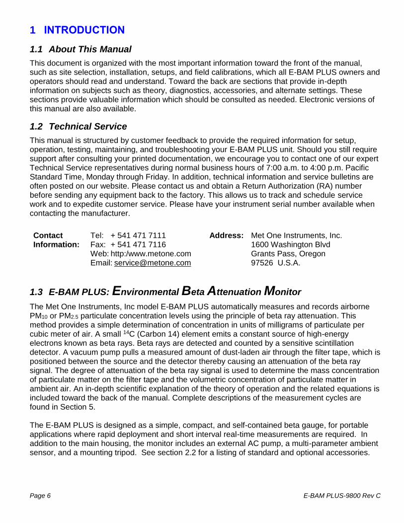
1.3 E-BAM PLUS: Environmental Beta Attenuation Monitor
The Met One Instruments, Inc model E-BAM PLUS automatically measures and records airborne PM10 or PM2.5 particulate concentration levels using the principle of beta ray attenuation. This method provides a simple determination of concentration in units of milligrams of particulate per cubic meter of air. A small 14C (Carbon 14) element emits a constant source of high-energy electrons known as beta rays. Beta rays are detected and counted by a sensitive scintillation detector. A vacuum pump pulls a measured amount of dust-laden air through the filter tape, which is positioned between the source and the detector thereby causing an attenuation of the beta ray signal. The degree of attenuation of the beta ray signal is used to determine the mass concentration of particulate matter on the filter tape and the volumetric concentration of particulate matter in ambient air. An in-depth scientific explanation of the theory of operation and the related equations is included toward the back of the manual. Complete descriptions of the measurement cycles are found in Section 5. The E-BAM PLUS is designed as a simple, compact, and self-contained beta gauge, for portable applications where rapid deployment and short interval real-time measurements are required. In addition to the main housing, the monitor includes an external AC pump, a multi-parameter ambient sensor, and a mounting tripod. See section 2.2 for a listing of standard and optional accessories.

E-BAM PLUS-9800 Rev C Page 7
1.4 Beta Radiation Safety Statement
The Met One Instruments E-BAM PLUS contains a small 14C (Carbon 14) beta radiation-emitting source. The nominal activity of the source is 60 microcuries, which is below the “Exempt Concentration Limit” as defined in 10 CFR Section 30.71 – Schedule B. The owner of an E-BAM PLUS is not required to obtain any license in the United States to own or operate the unit. The owner of an E-BAM PLUS may elect to return the entire unit to Met One Instruments for recycling of the 14C source when the unit has reached the end of its service life, although the owner is under no obligation to do so. Under no circumstances should anyone but factory technicians attempt to remove or access the beta source. The beta source has a half-life of about 5730 years, and should never need to be replaced unless it becomes damaged or corroded. Neither the 14C source nor the beta particle detector are serviceable in the field. Should these components require repair or replacement, the E-BAM PLUS must be returned to the factory for service and recalibration. The E-BAM PLUS is manufactured in compliance with the U.S. NRC safety criteria in 10 CFR 32.27.
1.5 The E-BAM PLUS and U.S. EPA Equivalent Methods
The E-BAM PLUS is US-EPA designated for PM10 under the following designation number:
• Designation Number: EQPM-1215-226 US-EPA designated methods using the E-BAM PLUS may be modified from time to time in order to reflect hardware or software improvements. These modifications do not impact previously designated configurations of the E-BAM PLUS but may provide the end user with a product upgrade path that will allow the monitor to continue to be operated as a US-EPA designated method. For further details, please contact our service department. Details concerning USEPA designated configurations of the E-BAM PLUS may be found on the US-EPA website: https://www3.epa.gov/ttnamti1/files/ambient/criteria/AMTIC%20List%20Dec%202016-2.pdf

Page 8 E-BAM PLUS-9800 Rev C
1.6 E-BAM PLUS Specifications
PARAMETER SPECIFICATION*
Measurement Principle Particulate Concentration by Beta Attenuation
U.S. EPA Designations Outdoor PM10 FEM Configuration
Measurement Range -15 g/m3 – 10,000 g/m3
Measurement Accuracy Exceeds US-EPA Class III PM10 FEM standards for additive and multiplicative bias
Measurement Resolution 1.0 g/m3
Lower Detection Limit (2σ) (1 hour) Less than 10 g/m3
(2σ) (24 hour) Less than 2 g/m3
Measurement Sample Time 1 Hour
Flow Rate 16.7 L/min inlet flow rate; actual volumetric flow
Filter Tape Continuous glass fiber filter; 30 mm x 21 m roll; > 60 days/roll
Span Check Manual
Beta Source C-14 (carbon-14); 60 µCi ±15 µCi (< 2.22 X 10⁶ Beq); Half-Life 5730 years
Beta Detector Type Photomultiplier tube with organic plastic scintillator
Operating Temperature Range
-25° to +50°C.
Operating Humidity Range 0 – 90% RH, noncondensing
Inlet Humidity Control Actively controlled inlet heater module; 0 - 50 C filter temperature set point
User Interface 4.3” graphical touch screen
Ambient Sensor Model 597 combination AT, RH, and BP serial sensor
AT: -50° to +70°C; RH: 0 to 98%; BP: 375 to 825 mmHg
Analog Outputs 2 channels; optically isolated; Voltage range 0–1 VDC, 0–2.5 VDC, 0–5 VDC
Current range 4–20 mA
Alarm Output 1 channel; dry NO contact; 1 A at 125 VAC or 60 VDC maximum.
7500 Digital Serial Interface 2 channels, half duplex RS-485
Serial Interface 1 channel; full duplex RS-232 and USB (Shared common serial output)
Baud rates 1200, 2400, 4800, 9600, 19200, 38400, 57600, 115200
Internal Data Storage 8 Days 1-minute average, 1.3 years 60-minute average
External Data Storage 1 USB Flash drive device
Compatible Software Air Plus 5, Comet™, HyperTerminal®
Power Supply AC Version: 100 - 230 VAC; 50/60 Hz; 150 W, 3 A @115 VAC / 2 A @230 VAC
Weight 75 lbs. (34 kg) (Top unit 35 lbs., Pump box 40 lbs.)
Dimensions (Without Tripod) Height: 18” (46 cm) Width: 16” (41 cm) Depth: 12” (31 cm) * Specifications may be subject to change without notice. † The hourly detection limit is defined as twice the standard deviation of the hourly zero noise of the instrument. The 24 hour detection limit is defined as the hourly detection limit divided by the square root of 24 (approximately 4.9).

E-BAM PLUS-9800 Rev C Page 9
2 E-BAM PLUS INSTALLATION AND COMMISSIONING This section describes assembly, start-up, and filter tape installation for the E-BAM PLUS unit.
2.1 Unpacking
Any damage incurred to the equipment during shipping are the responsibility of the carrier. If any damage to the shipment is noticed before unpacking, a claim must be filed with the commercial carrier immediately. You should follow any special unpacking instructions provided by the carrier as you then carefully remove all items from the containers and inspect each component. It is recommended to document and photograph all damaged packages and items before, during, and after unpacking them. Contact Met One Instruments (see section 1.2 of this manual) to arrange for any replacement items needed.
Unpack the mass monitor and accessories and compare them to the packing list to make sure all items are present.
The E-BAM PLUS is shipped with the plastic shipping shim installed under the nozzle which prevents the moving parts of the vane assembly from being damaged in transit. The shim must be replaced anytime the mass monitor is being transported in order to avoid damaging the vane control mechanism. Do not ship or transport the E-BAM PLUS with filter tape installed.
Please keep all of the special shipping items (box, foam packing material, etc.) used to ship your E-BAM PLUS. They should be re-used if you must transport your monitor (changing site locations, returning to the factory, etc.). Met One is not responsible for damage to the mass monitor if shipped in non-original packaging, or without the shim in place. Contact Met One Instruments (see section 1.2 of this manual) for replacement packing materials if necessary.
2.2 Accessories
Every E-BAM PLUS requires the use of ancillary components. The items supplied with a standard E-BAM PLUS PM10 FEM monitoring system are as follows:
Standard Components Part No.
Mounting Tripod EX-905
External AC Pump Box EX-225 (120 VAC) or EX-226 (230 VAC)
PM10 Size Selective Inlet BX-802
Inlet Tube (10 inches) 81183
Ambient Combination Sensor (AT, BP, RH) 597 w/ 82170 Cable Assembly
Filter Tape 460180
Accessory Kit* 82388
*See section 8 for a complete listing of all items contained in the Accessory Kit

Page 10 E-BAM PLUS-9800 Rev C
Application and installation dependent accessories for the E-BAM PLUS are available from Met One Instruments.
Common Optional Component Part No.
Wind Speed and Direction Sensor EX-MSO or EX-AIO
PM2.5 Very Sharp Cut Cyclone BX-807
Volumetric Flow Calibration Kit BX-307
Zero Filter Kit BX-302
2.3 Assembling the E-BAM PLUS
The E-BAM PLUS is designed to be field deployable by an average person in less than 15 minutes under normal conditions. Refer to the photos and diagrams below while performing the following steps to assemble the unit:
1. Deploy the tripod: Remove the three stainless steel detent pins from the tripod base by pulling the rings. Unfold the three tripod legs and reinsert the three pins so that each pin secures a leg in the open position. Make sure the erected tripod is rigid and stable.
Figure 2-1 Tripod Deployment
2. Install the E-BAM PLUS onto the tripod: Lift the E-BAM PLUS assembly and slide the slot on the back of the E-BAM PLUS over the tab on the top of the tripod. Insert the supplied ¼-20 bolt through the tab on the bottom of the E-BAM PLUS and through the hole in the body of the tripod (see Figure 2-2). Secure it with the supplied washers and nut. This prevents the E-BAM PLUS from shifting on the tripod.
3. Install the inlet components: Loosen the weatherproof fitting on top of the E-BAM PLUS and insert the short inlet tube into the top of the unit. The tube must go through the fitting and through two O-rings in the top of the E-BAM PLUS. Make sure the tube is fully seated by rotating it back and forth. Tighten the weatherproof fitting to secure the inlet tube. For PM10 monitoring, install the BX-802 PM10 inlet directly onto the top of the short inlet tube. If a BX-807 cyclone is to be used for PM2.5 monitoring, it must be installed under the PM10 head as shown in Figure 2-2. Lubricate the O-rings as necessary.
Detent Pins

E-BAM PLUS-9800 Rev C Page 11
Figure 2-2 Tripod Mounting of the E-BAM PLUS
4. Install 597 Sensor: Connect the 597 sensor to the post on the back of the tripod with the supplied mounting hardware (user supplied 7/16” wrench required). The 597 sensor should face away from the E-BAM PLUS as shown in Figure 2-3. Verify configuration after power-up as detailed in section 2.7.1.
Figure 2-3 Mounting the 597 Sensor
5. Optional Wind Sensor: If an optional wind speed/direction sensor (such as the EX-MSO or EX-AIO) is supplied (see section 10.2), then the E-BAM PLUS will come with a cross-arm tube to use for mounting the 597 and the wind sensor. Connect the cross-arm to the post on the back of the tripod with the supplied ¾” x ¾” fitting and set screws and then install the sensors at opposite ends of the arm as suggested in Figure 2-4. The wind sensor should be as far from the E-BAM PLUS unit as possible, and the wind vane must be able to rotate fully without hitting anything. Plug the wind sensor into the corresponding connector on the bottom of the E-BAM PLUS. Depending on the type of wind sensor, it may need to be oriented to the north. Consult the separate manual that comes with the wind sensor for details. Verify configuration after power-up as detailed in section 2.7.2.
Mounting Tab
Bolt
Short Inlet Tube
BX-802 PM10 Head
BX-807 PM2.5 Sharp Cut Cyclone
Weatherproof Fitting
597 Sensor
Page 12 E-BAM PLUS-9800 Rev C
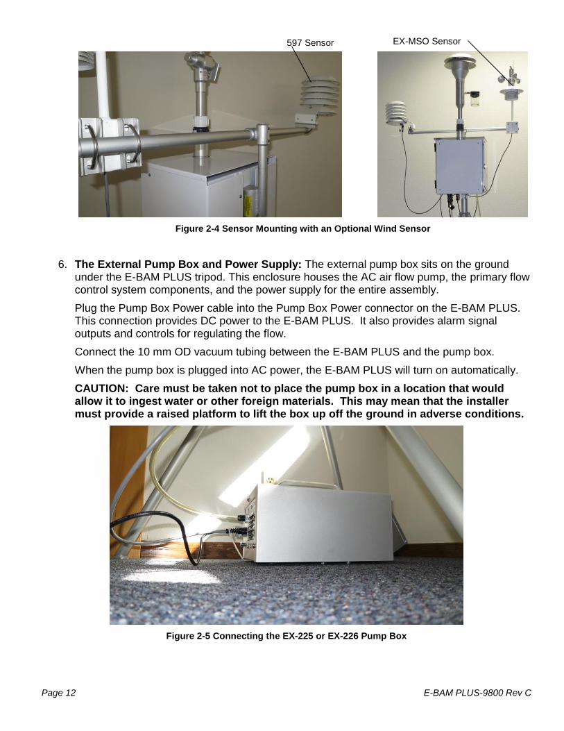
Figure 2-4 Sensor Mounting with an Optional Wind Sensor
6. The External Pump Box and Power Supply: The external pump box sits on the ground under the E-BAM PLUS tripod. This enclosure houses the AC air flow pump, the primary flow control system components, and the power supply for the entire assembly.
Plug the Pump Box Power cable into the Pump Box Power connector on the E-BAM PLUS. This connection provides DC power to the E-BAM PLUS. It also provides alarm signal outputs and controls for regulating the flow.
Connect the 10 mm OD vacuum tubing between the E-BAM PLUS and the pump box.
When the pump box is plugged into AC power, the E-BAM PLUS will turn on automatically.
CAUTION: Care must be taken not to place the pump box in a location that would allow it to ingest water or other foreign materials. This may mean that the installer must provide a raised platform to lift the box up off the ground in adverse conditions.
Figure 2-5 Connecting the EX-225 or EX-226 Pump Box
597 Sensor EX-MSO Sensor

E-BAM PLUS-9800 Rev C Page 13
2.4 Electrical Connections
The E-BAM PLUS has a set of weatherproof connectors on the bottom of the unit. These connectors provide the connections for the power supply, external sensors, communications, and control of the external pump box.
The E-BAM PLUS chassis ground lug should be connected to an earth ground whenever possible, to reduce electrical noise in the unit.
Figure 2-6 E-BAM PLUS Connectors
Figure 2-7 E-BAM PLUS Pump Box Connections

Page 14 E-BAM PLUS-9800 Rev C
Pump Box Power WS/WD Sensor Analog Output Pin Function Pin Function Pin Function
A PUMP + A +V IN A ANALOG 1 I/V
B PUMP - B PWR GND B ISO GND
C FLOW CONTROL+ C SIG GND C ANALOG 2 I/V
D FLOW CONTROL- D RS-485 B D ISO GND
E GND E RS-485 A E SHIELD
F PUMP SENSE F SHIELD
G +5 V
H GND
J ALARM IN
K ALARM OUT
L POWER
M/N N/C
597 Sensor Cloud Serial RS-232 Serial Pin Function Pin Function Pin Function
A +V IN A RX A DC PWR
B PWR GND B TX B RX
C SIG GND C SHIELD C TX
D RS-485 B D CTS D/E GND
E RS-485 A E DTR F SHIELD
F SHIELD F DC PWR G 485 A
G GND H 485 B
I/J N/C
Figure 2-8 Connector Pin-Outs

E-BAM PLUS-9800 Rev C Page 15
Figure 2-9 E-BAM PLUS Topology
597 Sensor(AT, RH, BP)
AC Pump Box(EX-225 or EX-226)
Total Height83" PM10
Inlet Tube(81183)
BX-802PM10 Head
9170 Tripod
OptionalEX-MSO or
EX-AIO
E-BAM PLUS
Page 16 E-BAM PLUS-9800 Rev C
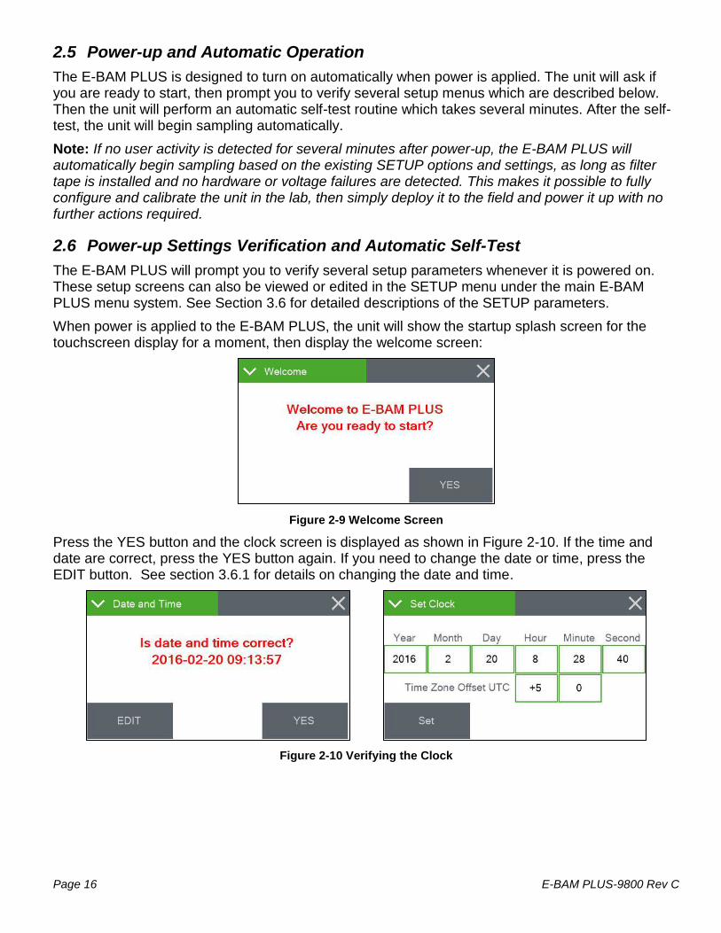
2.5 Power-up and Automatic Operation
The E-BAM PLUS is designed to turn on automatically when power is applied. The unit will ask if you are ready to start, then prompt you to verify several setup menus which are described below. Then the unit will perform an automatic self-test routine which takes several minutes. After the self-test, the unit will begin sampling automatically.
Note: If no user activity is detected for several minutes after power-up, the E-BAM PLUS will automatically begin sampling based on the existing SETUP options and settings, as long as filter tape is installed and no hardware or voltage failures are detected. This makes it possible to fully configure and calibrate the unit in the lab, then simply deploy it to the field and power it up with no further actions required.
2.6 Power-up Settings Verification and Automatic Self-Test
The E-BAM PLUS will prompt you to verify several setup parameters whenever it is powered on. These setup screens can also be viewed or edited in the SETUP menu under the main E-BAM PLUS menu system. See Section 3.6 for detailed descriptions of the SETUP parameters.
When power is applied to the E-BAM PLUS, the unit will show the startup splash screen for the touchscreen display for a moment, then display the welcome screen:
Figure 2-9 Welcome Screen
Press the YES button and the clock screen is displayed as shown in Figure 2-10. If the time and date are correct, press the YES button again. If you need to change the date or time, press the EDIT button. See section 3.6.1 for details on changing the date and time.
Figure 2-10 Verifying the Clock

E-BAM PLUS-9800 Rev C Page 17
After the time is verified, the unit will display the Settings screen shown in Figure 2-11 below. If the settings need to be changed, press the green bordered value box to be updated and the associated edit screen will be displayed.
This menu is important to understand. See Sections 3.6.5 and 3.6.6 for detailed descriptions of these parameters. Press OK if the settings are correct.
Figure 2-11 Verifying the Average Period
After confirming or setting the Location and Data Average settings, the E-BAM PLUS setup proceeds to the PM Inlet screen shown in Figure 2-12. If the settings need to be changed, press the green bordered value box to be updated and the associated edit screen will be displayed.
This menu is also important to understand. See Section 3.6.17 for detailed descriptions of these parameters. Press OK if the settings are correct.
Figure 2-12 Verifying the Concentration Type
After verifying the CONCENTRATION TYPE, the E-BAM PLUS will need to check whether or not a roll of filter tape installed. First, you will be instructed to remove the shipping vane protector if it is installed. Then the monitor will then check the tape installation. If no tape is detected, the unit will prompt you to install a new roll:
Figure 2-13 Verifying Filter Tape is Loaded
Install a roll of filter tape as described in Section 2.8. When the filter tape is installed, press MOVE. The unit will again try to detect the tape.
If tape is detected, the unit will proceed with a self-test. After a successful self-test, the monitor will wait for one minute and then begin sampling.

Page 18 E-BAM PLUS-9800 Rev C
2.7 Configuring External Sensors
The E-BAM PLUS must have a 597 sensor connected and properly configured for operation. If the 597 is not present, the E-BAM PLUS will not begin sampling. See section 10.2 for more details about available wind sensors.
2.7.1 Configuring the 597 Sensor
The E-BAM PLUS requires a 597 sensor at address 1 of its serial network to begin sampling. Once the physical connections are made (see section 2.3), the sensor is programmed using the Digital Link screen located in the Test menu (see section 3.5.15).
Upon entering the Digital Link screen, any digital sensor connected to the E-BAM PLUS with address 1 or 2 programmed in it will appear in either the Sensor 1 or Sensor 2 fields, as appropriate. In addition to the sensor type, the address fields on this screen also display the firmware currently installed in the sensor. Figure 2-14 shows a typical configuration.
Figure 2-14 The Digital Link Screen
The State field indicates that the E-BAM PLUS is either starting up digital communications or waiting for a response from the sensor. If either the sensor type or firmware revision is missing or incorrect, communications are not properly established with the sensor. The grey SETUP button in the lower left corner provides access to the Digital Setup screen for configuring the addresses of the digital sensors. See section 2.7.2 for details.
2.7.2 Changing Sensor Addresses
The default address for most digital sensors provided by Met One Instruments, Inc. is to set the address to 1.
If a connected sensor has an address other than 1 or 2, it can be located in the Digital Setup screen by pressing the grey SCAN button in the bottom left corner (see Figure 2-15). The E-BAM PLUS will scan through all potential network address nodes in an attempt to locate any connected devices. Progress of this scan can be seen in the third address field label (which displays Addr 3, by default) and the word “Scanning” will appear in the field itself.
Figure 2-15 Scanning for Sensors in the Digital Setup Screen
If a device is located at some other address, it can be changed by pressing the grey CHANGE button next to the third address field. In the example shown in Figure 2-16 , the 597 has been configured for address 43. Pressing the grey SET 1 button will update the address in the sensor to address number 1 and exit back to the main Digital Link screen. The Sensor 1 field will now display the 597 details similar to Figure 2-14.
Figure 2-16 The Change Address Screen
If two sensors share the same address, disconnect one of them and then use the CHANGE button to set the other one to a different address. Remember that the 597 must be configured for address number 1 and if an optional wind sensor is connected, it will need to be set to number 2.

E-BAM PLUS-9800 Rev C Page 19
2.8 Filter Tape Loading
Filter tape must be loaded into the E-BAM PLUS for sampling. One roll of tape will last anywhere from a few weeks to more than a year, depending on the Tape Advance setting (see section 3.6.12) and ambient particulate levels. It is important to have spare rolls of tape available to avoid data interruptions. Used filter tape should never be “flipped over” or re-used. This will result in inaccurate measurements! Loading a roll of filter tape is a simple matter using the following steps:
1. If the vane is in the up position, it will need to be lowered. Enter the Load Filter Tape screen in the Operate menu. The unit will lower the vane and prompt you to load the tape.
2. If you are replacing a used roll of tape. Remove the old roll, then thoroughly clean the nozzle and vane as described in Section 6.5.1.
3. An empty core tube must be installed on the left (take-up) reel hub. This provides a surface for the used tape to spool-up on. Met One supplies a plastic core tube to use with the first roll of tape. After that, you can use the empty cardboard core tube left over from your last roll to spool-up the new roll. Never fasten the filter tape directly to the aluminum hub!
4. Load the new roll of filter tape onto the right (supply) reel, and route the tape through the nozzle area as shown in Figure 2-17. Attach the loose end of the filter tape to the empty core tube with tape.
5. Rotate the tape roll to remove excess slack, then install the plastic spool covers tightly. The spool covers clamp the tape rolls to the hubs to prevent them from slipping.
6. Press the grey MOVE button to verify tape is properly loaded. 7. Press the X button to return to the Operate menu.
Figure 2-17 Proper Loading of the Filter Tape
2.9 Warm-up Period
The E-BAM PLUS must warm up for at least one hour before optimum accuracy of the concentration data can be obtained. This is because the beta detector contains a vacuum tube which must stabilize. This applies any time the unit is powered up after being off for more than a moment. Setups, tests, and flow calibrations can be performed during this warm up time. The first hour of data should often be discarded or ignored.

Page 20 E-BAM PLUS-9800 Rev C
3 E-BAM PLUS USER INTERFACE and MENU SYSTEM
This section describes the E-BAM PLUS user interface system, and describes the functions of the main menu options, including how to view data and errors.
Figure 3-1 The E-BAM PLUS User Interface
3.1 The User Interface - Touchscreen Display Functions
The E-BAM PLUS user interface is a touchscreen display used to control almost all of the features and functionality of the E-BAM PLUS. It is mounted on a fixed stainless steel plate inside the enclosure near in the upper left hand corner of the monitor.
3.2 Main Operating Screen
In addition to the last hourly concentration reading, this screen shows the current real-time values being measured and the operational state of the E-BAM PLUS. This image below on the left hand side is the screen that will normally be displayed.
Figure 3-2 The E-BAM PLUS Main Operating Screens
Note that the display has a limited amount of space and cannot show all of the real time data on one screen. Tap down arrow key in the lower left corner of the display to navigate between the four screens shown in Figure 3-2.

E-BAM PLUS-9800 Rev C Page 21
Table 3-1 describes the other parameters visible in the main sampling display as shown in Figure 3-2. In addition to the hourly and real-time average concentrations, these are all of the logged parameters in the E-BAM PLUS:
Parameter Description
FLOW Primary air flow rate in actual LPM.
AT Ambient temperature in degrees C.
RH Ambient RH.
BP External barometric pressure.
FT Filter temperature in degrees C.
FRH Internal filter RH.
BV DC power supply voltage.
WS Wind speed in meters per second (if equipped).
WD Wind direction in degrees (if equipped).
Table 3-1 Main Display Parameter Descriptions

Page 22 E-BAM PLUS-9800 Rev C
3.3 Menu Hierarchy and Navigation
The E-BAM PLUS menu structure is outlined in the following table.
Main Menu Sub Menu Options Overview
Operate
See section 3.4
Start Sample
Load Filter Tape
Transfer Data
About
Begin or resume monitoring.
Load and properly tension the filter tape
Download stored data to a USB memory stick
Details the current E-BAM PLUS firmware type and version number
Test
See section 3.4.5
Leak Test
Ambient Temperature
Ambient Pressure
Flow Calibration
Run Self-Test
Parameters
Filter Sensors
Span Mass Audit
Tape Test
Vane/Count Test
Analog Output Cal
Analog Output Test
Inlet Heater
Relay Test
Input Test
Digital Link
Perform the leak test
Calibrate ambient temperature or restore default settings
Calibrate ambient pressure or restore default settings
Calibrate flow rate or restore default settings
Run the E-BAM PLUS Self-Test
Review current settings
Calibrate filter temp, pressure, and RH or restore default settings
Run the zero and span foil tests
Verify tape travels expected distance
Test vane operation and verify beta counting
Calibrate the analog output
Test the analog output
Manually turn the inlet heater on and off
Manually open and close the alarm relay
Test the digital clock sync input
Test and configure communications with digital sensors
Setup
See section 3.6
Set Clock
Clear memory
Background
Serial Port
Location
Data Average
Real-Time Period
Hourly Report
Analog Outputs
Conc. Units
Inlet Heater
Tape Advance
Change Password
Sound Volume
Touch Calibrate
Standard Temp
PM Inlet
Set the date and time
Clear all stored data
Change the concentration offset
Set the baud rate and connection type for serial communications
Set the location number used to identify the E-BAM PLUS
Set the averaging interval for collecting other than hourly data
Set the averaging interval for collecting real time data
Set the type of time stamp to use for the hourly report
Set the parameters for both analog outputs
Set the concentration units
Set the RH threshold for the inlet heater to activate
Set the differential pressure threshold for advancing the filter tape
Change the master password
Adjust the volume of the touchscreen sounds
Calibrate the touch screen
Set the Standard Temp to use for standard conditions flow calculations
Set sampling (PM10/PM2.5) and flow calculation types
Alarms
See section 3.7
No sub menu View alarms
Table 3-2 Main Display Parameter Descriptions
Menu selections and instructions are detailed in the following sections of this operating manual as detailed in the Main Menu column Table 3-2 above.

E-BAM PLUS-9800 Rev C Page 23
To access the various main menus, press the three horizontal lines in the top left corner. A drop down menu will appear (Figure 3-3) to allow selection of any of the four main menus. This option is available on all main menu screens (such as the Setup Menu shown in Figure 3-4) and on the main operating screen.
Figure 3-3 Main Menu Drop Down Selections
Figure 3-4 Setup Menu
To return to the main operating screen (see section 3.2), press the Home icon located in the upper right corner of all main menu screens. This icon can clearly be seen in the Setup Menu image shown here on Figure 3-4.
To cancel and action and return to the previous menu screen, press the X icon located in the upper right corner of all sub menu screens. This icon can clearly be seen in the Set Clock screen image in Figure 3-5.
Figure 3-5 Set Clock Screen
Figure 3-6 Visual Keypad for Numeric Entry
Some parameters, such as the Date and Time settings (Figure 3-5) or a Location value, require numeric entry. When you press the button to edit such a field, a visual keypad (Figure 3-6) will open up and allow you to input the value. Press the OK key to accept the changes or the Cancel key to return to the previous screen. The X key on the far right performs a backspace operation.

Page 24 E-BAM PLUS-9800 Rev C
3.4 Operate Menu
The Operate Menu is the doorway to the most commonly used areas for normal operation of the E-BAM PLUS.
Figure 3-7 The Operate Menu
3.4.1 Start Sample
This screen allows users to both start and stop the E-BAM PLUS sampling process. Upon entering this screen, a warning will be displayed asking users if they would like to start or stop a sample, depending on the current state of the monitor. If there is no sample currently being taken, the grey button in the lower left corner will be labeled START. If there is a sample in progress, it will read STOP.
Figure 3-8 The Start Sample Screen
3.4.2 Load Filter Tape
This menu option is used for filter tape installation. Load the tape and press the MOVE key to go back to the main menu. See section 2.8 for details.
Figure 3-9 The Load Filter Tape Screen
3.4.3 Transfer Data
Copying data to a USB memory stick is performed from this screen. See section 7.2 for detailed instructions.

E-BAM PLUS-9800 Rev C Page 25
3.4.4 About
This screen shows the monitor’s serial number and installed firmware type and version number. It also provides the CPLD firmware type and version in the CPLD Version field.
Figure 3-10 The About Screen
3.4.5 Prepare Shipping
This screen provides a means of inserting the shipping shim and securing it in place for transporting the instrument. To use it, simply press the Prepare Shipping field on the main Operate Menu. The vane will lower and instruct users to insert the shipping device (see Figure 3-11). Once inserted, the vane will automatically raise and lock the shim in place. At this point, the display will change to indicate that the E-BAM PLUS may be shut down. Remove power from the monitor and it is now ready to be disassembled and relocated.
Figure 3-11 The Prepare Shipping Screens
3.5 Test Menu
The Test Menu provides a means of testing and calibrating individual sensor inputs and calculations. Because these settings directly impact flow and concentration values, most of these tests are password protected.

Page 26 E-BAM PLUS-9800 Rev C
Figure 3-12 The Test Menus
3.5.1 Leak Test
All flow regulation is disabled while in this screen!
This screen provides the options and indications needed to perform a leak test of the sampling system. The grey pump control button in the lower left corner will read PUMP ON which indicates that pressing it will turn on the pump. Similarly, when the pump is running, this button will display PUMP OFF.
Figure 3-13 The Leak Test Screen
The grey vane control button in the lower right corner will always be labeled as VANE when you first enter this test screen. Pressing it will cause the vane to change state from up to down or down to up. The button will now display what will happen if you press it again, just like the pump control button. This means that it will read VANE UP if the vane is in the down position or VANE DOWN if it is in the up position.
The flow and lower pressure sensor indications are provided for reference when performing the leak test. See section 6.2 for detailed instructions on performing a leak test.
3.5.2 Ambient Temperature
This screen provides the options and indications needed to default, verify, and calibrate the ambient temperature sensor as part of the flow audit and calibration. See section 6.6 for detailed instructions.
Figure 3-14 The Ambient Temperature Screen
3.5.3 Ambient Pressure
This screen provides the options and indications needed to default, verify, and calibrate the ambient pressure sensor as part of the flow audit and calibration. See section 6.7 for detailed instructions.
Figure 3-15 The Ambient Pressure Screen
3.5.4 Flow Calibration
These four screens provide the options and indications needed to default, verify, and calibrate the various flow sensors as part of the flow audit and calibration procedures. See section 6.8 for detailed instructions.
Figure 3-16 Flow Calibration Screen (1 of 4)
E-BAM PLUS-9800 Rev C Page 27
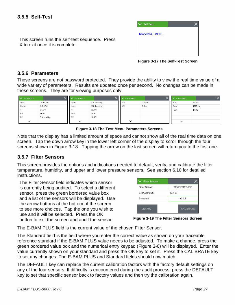
3.5.5 Self-Test
This screen runs the self-test sequence. Press X to exit once it is complete.
Figure 3-17 The Self-Test Screen
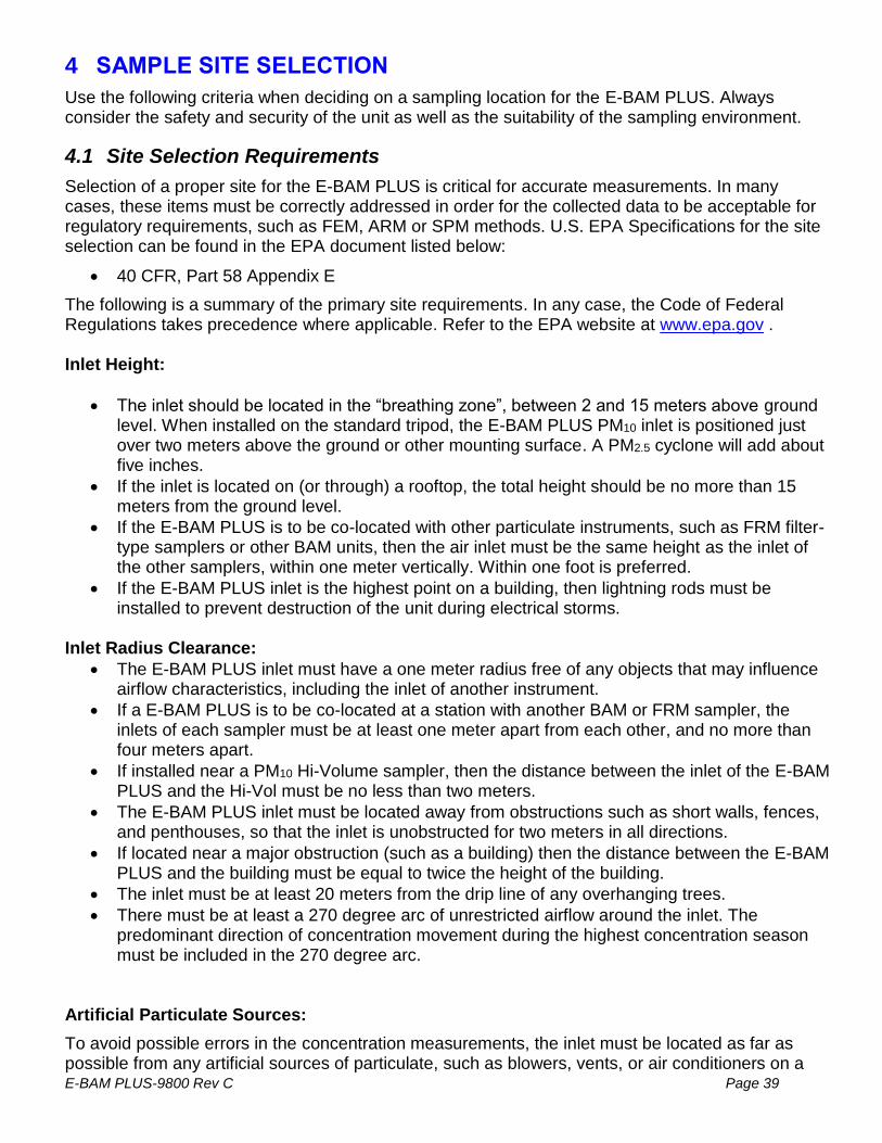
3.5.6 Parameters
These screens are not password protected. They provide the ability to view the real time value of a wide variety of parameters. Results are updated once per second. No changes can be made in these screens. They are for viewing purposes only.
Figure 3-18 The Test Menu Parameters Screens
Note that the display has a limited amount of space and cannot show all of the real time data on one screen. Tap the down arrow key in the lower left corner of the display to scroll through the four screens shown in Figure 3-18. Tapping the arrow on the last screen will return you to the first one.
3.5.7 Filter Sensors
This screen provides the options and indications needed to default, verify, and calibrate the filter temperature, humidity, and upper and lower pressure sensors. See section 6.10 for detailed instructions.
The Filter Sensor field indicates which sensor is currently being audited. To select a different sensor, press the green bordered value box and a list of the sensors will be displayed. Use the arrow buttons at the bottom of the screen to see more choices. Tap the one you wish to use and it will be selected. Press the OK button to exit the screen and audit the sensor.
Figure 3-19 The Filter Sensors Screen
The E-BAM PLUS field is the current value of the chosen Filter Sensor.
The Standard field is the field where you enter the correct value as shown on your traceable reference standard if the E-BAM PLUS value needs to be adjusted. To make a change, press the green bordered value box and the numerical entry keypad (Figure 3-6) will be displayed. Enter the value currently shown on your standard and press the OK key to set it. Press the CALIBRATE key to set any changes. The E-BAM PLUS and Standard fields should now match.
The DEFAULT key can replace the current calibration factors with the factory default settings on any of the four sensors. If difficulty is encountered during the audit process, press the DEFAULT key to set that specific sensor back to factory values and then try the calibration again.

Page 28 E-BAM PLUS-9800 Rev C
3.5.8 Span Mass Audit
This screen runs the Span Mass Audit. The sequence begins as soon as you enter it. See section 6.9 for detailed instructions.
3.5.9 Tape Test
This screen will allow you to verify proper installation and operation of the filter tape and motors. Press the grey TEST TAPE button to advance the tape. The pass criteria is ≥ 12 mm. The status of the tape, such as OK or if there is a Tape Break error, will be displayed to the right of the TEST TAPE button.
Figure 3-20 The Tape-Test Screen
3.5.10 Vane/Count Test
The Vane/Count Test screen provides the ability to manually raise and lower the vane. Pressing the grey VANE button will cause the vane to change state. When the vane is in the up position, you can also verify the monitor is beta counting correctly. The frequency for beta counts should be greater than 500 Hz.
Figure 3-21 The Vane/Count-Test Screen
Counting should only occur when the vane is in the up position. Figure 3-21 shows a typical count value for the Beta Count field. The 1-Minute Count test is for troubleshooting purposes with factory support technicians and will not commonly be used when deployed. Pressing the grey START button will begin the 1-Minute Count test. The counts displayed in the 1-Minute Count field will start from zero and begin counting up. A 60 second countdown timer will be shown in parenthesis next to the count value. In Figure 3-21, there are 41 seconds remaining in the 1-Minute Count test that is being performed.
3.5.11 Analog Output Calibration
This screen allows for calibration of the two analog output channels.
The channel field defines whether you are adjusting output number one or two. Tap the green bordered Channel selection box and pick the channel you need to test. The full scale range will be displayed in the Range value box. If you wish to change the full-scale value, see section 3.6.9.
Figure 3-22 The Analog Output Calibration Screen
After selecting the output channel, the measure field may be adjusted to maximum or minimum value and the output of the channel confirmed. Just tap the green bordered Measure box and select the desired test output. Verify the actual output using a voltmeter at the appropriate channel terminals on the bottom panel of the E-BAM PLUS (see section 2.4) or at the connected data logger input terminals.

E-BAM PLUS-9800 Rev C Page 29
If the output is not correct, use the up and down arrow keys to modify the Adjust field. When the FINE/COARSE selection is set to FINE, units will be incremented by one. If it is set to COARSE, the units will be incremented in tens. Tap the button to swap between the options.
Pressing the X key to exit the screen will save any adjustments that have been made. To clear any custom settings and restore the factory defaults, press the grey RESET button.

Page 30 E-BAM PLUS-9800 Rev C
3.5.12 Analog Output Test
To test the analog output channels, select channel number one or two on the top row marked Channel by pressing the green bordered Channel selection box. Using the Conc Output field, the output selection may now be set to any concentration value within the defined range (see section 3.6.9 and 3.6.10).
Figure 3-23 The Analog Output Test Screen
To make a change, press the Conc Output green bordered value box and the numerical entry keypad (Figure 3-6) will be displayed. Enter the desired concentration value to test and press the OK key to set it.
You’ll notice the Min Out and Max Out fields match the zero and full scale values for the selected output. Between them is the Set Out field, which will update with the expected output based on the concentration selected. See section 6.11 for instructions on performing an Analog Output audit.
3.5.13 Inlet Heater
This screen allows manual operation of the inlet heater assembly. Press ON to turn the heater on and verify the element heats up as expected. Press OFF to turn the heater off; verify it shuts off and then cools down. Exiting this test screen will also turn off the heater if you forget to turn it off when you are done testing.
Figure 3-24 The Inlet Heater Test Screen

E-BAM PLUS-9800 Rev C Page 31
3.5.14 Relay Test
This screen allows manual operation of the external alarm relay. Press CLOSE and the NO (normally opened) relay should close its contacts. Press OPEN to reverse its state back to normal conditions. The relay output terminals are located inside the pump box on the tan and violet leads (see Figure 3-26).
Figure 3-25 The Relay Test Screen
Figure 3-26 AC Pump Box Alarm Relay Terminal Locations
3.5.15 Digital Link
Test digital communications with the 597 by entering this screen. The 597 firmware version should be displayed when the proper link is established. See section 2.7 for details on how to configure the 597 sensor, as well as any optional wind sensors that may be connected.
Figure 3-27 The Digital Link Test Screen

Page 32 E-BAM PLUS-9800 Rev C
3.6 Setup Menu
The Setup Menu grants access to the configuration of the majority of the operating parameters for the E-BAM PLUS. It allows you to change offsets, clear the memory, set the date and time, and much more. Because of the changes able to be made, the Setup Menu is password protected.
Figure 3-28 The Setup Menus
Note that the display has a limited amount of space and cannot show all options on one screen. Tap the “>More…” and “>Back…” keys in the lower right corner of the display to navigate between the two screens shown in Figure 3-28.
3.6.1 Set Clock
3.6.2 Clear Memory
The alarm and data logs may be cleared from this screen. Press the green bordered file selection box and choose from the alarm log, data log, or all logs options. Press the Clear key in the lower left corner to erase the selection.
Figure 3-30 The Clear Memory Screen
The alarm and data logs may be cleared from this screen. Press the green bordered file selection box and choose from the alarm log, data log, or all logs options. Press the Clear key in the lower left corner to erase the selection.
Figure 3-31 The Clear Memory Screen
This is where you set the date and time. Press the green box of the field you wish to modify. The numerical entry keypad (Figure 3-6) will be displayed and allow you to enter the value for that parameter. Once all fields have been entered, press the grey Set button in the lower left corner to set them.
Figure 3-29 The Set Clock Screen

E-BAM PLUS-9800 Rev C Page 33
3.6.3 Background
The background value is the zero correction (offset) for the E-BAM PLUS concentrations. It is applied to all data collected to compensate for measured mass in the absence of any particulate matter. This screen allows you to edit your background zero correction factor after performing a zero test with the BX-302 Zero Filter. See section 6.4
Figure 3-32 The Background Screen
Press the green bordered value box and the numerical entry keypad (Figure 3-6) will be displayed. Enter the new calculated correction factor. Regardless of the concentration units setting (see section 3.6.10), the background is always entered in units of mg/m3.
Met One supplies the E-BAM PLUS with a factory-set background value. Use the BX-302 zero filter kit to audit the background value and set it for local conditions. See the BX-302-9800 manual for the zero test procedure or contact the Met One Instruments service department (see section 1.2) for more information.
WARNING: This calibration value may significantly affect the accuracy of the unit.
The grey ADVANCED button in the lower left corner provides access to the K factor setting for the E-BAM PLUS. This should NOT be adjusted unless directed by factory personnel. It is set at the factory and altering it will void the unit’s calibration.
3.6.4 Serial Port
This is where your serial communication settings are configured. You can set the baud rate, the type of flow control you wish to use, and whether or not the monitor is communicating with an Airsis satellite modem. Press the green bordered value box and a list of the settings available will be displayed.
Figure 3-33 The Serial Port Screen
Tap the setting you wish to use and it will be applied.
The baud rate options are 1200, 2400, 4800, 9600, 19200, 38400, 57600, and 115,200 while the flow control type can be either NONE or CTS/RTS. The CTS/RTS selection should ONLY be used when employing Ethernet port communications. All other modes should use the NONE flow control setting. The AIRSIS field can be set to ON or OFF. See section 10.1 for more details.
Press the OK key to lock in your choices. Section 7.4 has more details about serial communications.
3.6.5 Location
You may enter a four-digit location ID for the E-BAM PLUS. Press the green bordered value box and the numerical entry keypad (Figure 3-6) will be displayed. Enter the new location ID value.
Figure 3-34 The Location Screen

Page 34 E-BAM PLUS-9800 Rev C
3.6.6 Data Average
The default averaging period for the E-BAM PLUS is 60 minutes. If you would like to set an alternate averaging period, you may do so from this screen. Press the green bordered value box and the selection screen shown on the right of Figure 3-35 will be displayed. Not all choices are able to be presented at the same time. Use the up and down arrow keys under the displayed options to show additional selections Tap the one you wish to use and then press the OK button to set it. The available average periods are 1, 5, 10, 15, 30, and 60 minutes.
Figure 3-35 The Data Average Screens
3.6.6.1 Data Average Capacity
The E-BAM PLUS internal data logger can store 11,616 records. With a fixed number of records, the time until the internal logger is full will vary depending on the averaging period selected. The shorter the time interval, the faster the logger will fill up. Table 3-3 shows the approximate length of time in days, months, and years before the logger reaches full capacity. Once the circular memory is full, the E-BAM PLUS will begin overwriting the oldest data with the most recently collected data points.
Time Period in Minutes
Approximate Capacity in Days
Approximate Capacity in Months
Approximate Capacity in Years
1 8 0.3 0.0
5 40 1.3 0.1
10 81 2.7 0.2
15 121 4 0.3
30 242 8.1 0.7
60 484 16.1 1.3
Table 3-3 Approximate Data File Capacity in Time
3.6.7 Real-Time Period
The real-time concentration period is set on this screen. Press the green bordered value box and a list of the settings available will be displayed. Tap the one you wish to use and it will be applied. The available time periods are from 15 to 60 minutes in one minute increments. Contact the Met One Instruments service department for more details about the Real-Time measurement.
Figure 3-36 The Real-Time Period Screen

E-BAM PLUS-9800 Rev C Page 35
3.6.8 Hourly Report
The hourly report time stamp can be set to mark the data with the time from either the beginning or ending of the hour. For example, if set to BEGINNING, data collected during the hour from 8:00 to 9:00 would be marked as 8:00. Similarly, if that data were collected with ENDING as the choice, the data time stamp would be 9:00 instead.
Figure 3-37 The Hourly Report Screen
The factory default setting for this option is ENDING. Press the green bordered value box and a list of the settings available will be displayed. Tap the one you wish to use and it will be applied.
3.6.9 Analog Outputs
There are two analog output channels on the E-BAM PLUS. Analog Range 1 is the analog output for the real time concentration value (see section 3.6.7). Analog Range 2 is the analog output for the hourly concentration value (see section 5.1).
These are independently set to one of the following output ranges: 0-1.0 vdc, 0-2.5 vdc, 0-5.0 vdc, or 4-20 mA.
Figure 3-38 The Analog Outputs Screen
The span scale setting is applied to both channels. It can be set for 0-100 μg/m3, 0-200 μg/m3, 0-500 μg/m3, 0-1,000 μg/m3, 0-2,000 μg/m3, 0-5,000 μg/m3, or 0-10,000 μg/m3.
Similarly, there is only one Concentration offset value and it is also applied to both channels. It can be set from -15 μg/m3 to +5 μg/m3 in 5 μg/m3 increments.
No matter what is selected for the concentration units setting (see section 3.6.10), the scaling and offset is always entered in units of μg/m3.
To adjust the analog output settings, press the green bordered value box and a list of the settings available will be displayed. Tap the one you wish to use and it will be applied. See section 7.1 for information about connecting the analog output to an external data logger.
3.6.10 Concentration Units
For internal data logging purposes, the concentration units of the E-BAM PLUS can be set to either mg/m3 or μg/m3. To change this setting, press the green bordered value box and a list of the settings available will be displayed. Tap the one you wish to use and it will be applied.
Figure 3-39 The Conc Units Screen

Page 36 E-BAM PLUS-9800 Rev C
3.6.11 Inlet Heater
This screen affords users the opportunity to set the filter temperature at which the inlet heater will turn off. When the FT is below this threshold, it will activate. It can be set from 0 to 50 Deg C in one degree increments. Press the green bordered value box and the numerical entry keypad (Figure 3-6) will be displayed. Enter the new threshold value.
Figure 3-40 The Inlet Heater Screen
3.6.12 Tape Advance
The filter tape in the E-BAM PLUS will be automatically advanced at a specified time interval or whenever too much particulate has been deposited on it.
The automatic tape advance time is adjustable and can be set to 1, 2, 3, 4, 6, 8, 12, or 24 hours. It is recommended to use the greatest duration possible while avoiding an automatic advance due to a pressure drop error. This will allow for maximum tape usage over time. The shorter the advancement period is set, the faster the filter tape will be consumed.
Figure 3-41 The Tape Advance Screen
Heavy particulate buildup will result in an excessive pressure drop across the tape. If the pressure drop gets too large, the E-BAM PLUS will advance the filter tape to a clean spot and then continue sampling. This is to prevent straining the pump when sampling in air with higher contamination levels. The pressure threshold for this action can be set from 50 to 350 mmHg in one mmHg increments.
To change the Tape Period, press the green bordered value box and a list of the settings available will be displayed. Tap the one you wish to use and it will be applied.
To change the Tape Pressure, press the green bordered value box and the numerical entry keypad (Figure 3-6) will be displayed. Enter the new pressure threshold value and press the OK key to set it. Decimal values will be rounded up or down to the nearest whole number.
3.6.13 Password
Certain menus and options of the E-BAM PLUS are password protected. You may use any four digit password you would like and this is the screen you need to access to change it. Press the green bordered value box and the numerical entry keypad (Figure 3-6) will be displayed. Enter the new password.
Figure 3-42 The Password Screen
Setting the password to 0000 means no password is used.

E-BAM PLUS-9800 Rev C Page 37
3.6.14 Sound Volume
The touchscreen will beep every time a selection is made and that volume may be adjusted in this screen. Press the green bordered value box and the numerical entry keypad (Figure 3-6) will be displayed. You may enter a value from 0 – 100 with 100 being very loud and 0 being no beep at all.
Figure 3-43 The Sound Volume Screen
Any changes made here will not be active until exiting this screen.
3.6.15 Touch Calibrate
This screen allows for calibration of the touchscreen. Press the grey Calibrate button to begin and then simply follow the instructions on the screen to calibrate it. If each step is not completed within five seconds, the test will cancel itself and return to page two of the Setup menu.
Figure 3-44 The Touch Calibrate Screen
There is a countdown clock for this feature displayed on each step of the calibration process.
3.6.16 Standard Temp
The Standard Temperature setting is the value that will be used to calculate the flow volume whenever the monitor is set to STANDARD Conc Type (see section 3.6.17). This can be set to 25, 20, or 0 degrees C. In the United States, 25 degrees C is almost always used for standard temperature. Some other countries use 20 or zero degrees instead.
Figure 3-45 The Standard Temp Screen
If the E-BAM PLUS is set to ACTUAL concentration, the unit will ignore this setting and use the actual ambient temperature for the flow calculations.
3.6.17 PM Inlet
Use this screen to configure the E-BAM PLUS to identify the logged data as PM10 or PM2.5, or TSP particulate. To change either of these settings, press the green bordered value box you wish to edit and a list of the settings available will be displayed. Tap the one you wish to use and it will be applied.
Figure 3-46 The PM Inlet Screen
The concentration (Conc Type) determines whether the sample air volume is calculated using actual or standard conditions. Setting the concentration type to STANDARD will use the value set in the Standard Temp screen (see section 3.6.16) for temperature and the standard pressure of 760 mmHg. Setting the field to ACTUAL will use the actual ambient temperature and pressure values measured by the E-BAM PLUS for the flow calculations. This calculation then determines whether

Page 38 E-BAM PLUS-9800 Rev C
the concentration is recorded in Actual or Standard conditions. See section 9.1 for information about the conversion between Actual and Standard conditions.
3.6.18 Cloud Data
Data can be accessed remotely via a modem connection to the cloud.
Use this screen to configure the E-BAM PLUS modem communications. The Cloud Modem type can be set to either GSM or CDMA to provide compliance with most carriers worldwide. The modem type is set in the Cloud Modem field. The Clock Sync field provides an option to synchronize the clock in the E-BAM PLUS with the cloud clock, if needed.
Figure 3-47 The Cloud Data Screen
To change either of these settings, press the green bordered value box you wish to edit and a list of the settings available will be displayed. Tap the one you wish to use and it will be applied.
3.7 Alarms Menu
This screen is used to view time-stamped alarm events with the most recent alarm will be displayed first. Use the up and down arrow keys located at the bottom of the screen to scroll through the alarm log.
Figure 3-48 The Alarms Menu
E-BAM PLUS-9800 Rev C Page 39
4 SAMPLE SITE SELECTION
Use the following criteria when deciding on a sampling location for the E-BAM PLUS. Always consider the safety and security of the unit as well as the suitability of the sampling environment.
4.1 Site Selection Requirements
Selection of a proper site for the E-BAM PLUS is critical for accurate measurements. In many cases, these items must be correctly addressed in order for the collected data to be acceptable for regulatory requirements, such as FEM, ARM or SPM methods. U.S. EPA Specifications for the site selection can be found in the EPA document listed below:
• 40 CFR, Part 58 Appendix E
The following is a summary of the primary site requirements. In any case, the Code of Federal Regulations takes precedence where applicable. Refer to the EPA website at www.epa.gov . Inlet Height:
• The inlet should be located in the “breathing zone”, between 2 and 15 meters above ground level. When installed on the standard tripod, the E-BAM PLUS PM10 inlet is positioned just over two meters above the ground or other mounting surface. A PM2.5 cyclone will add about five inches.
• If the inlet is located on (or through) a rooftop, the total height should be no more than 15 meters from the ground level.
• If the E-BAM PLUS is to be co-located with other particulate instruments, such as FRM filter-type samplers or other BAM units, then the air inlet must be the same height as the inlet of the other samplers, within one meter vertically. Within one foot is preferred.
• If the E-BAM PLUS inlet is the highest point on a building, then lightning rods must be installed to prevent destruction of the unit during electrical storms.
Inlet Radius Clearance:
• The E-BAM PLUS inlet must have a one meter radius free of any objects that may influence airflow characteristics, including the inlet of another instrument.
• If a E-BAM PLUS is to be co-located at a station with another BAM or FRM sampler, the inlets of each sampler must be at least one meter apart from each other, and no more than four meters apart.
• If installed near a PM10 Hi-Volume sampler, then the distance between the inlet of the E-BAM PLUS and the Hi-Vol must be no less than two meters.
• The E-BAM PLUS inlet must be located away from obstructions such as short walls, fences, and penthouses, so that the inlet is unobstructed for two meters in all directions.
• If located near a major obstruction (such as a building) then the distance between the E-BAM PLUS and the building must be equal to twice the height of the building.
• The inlet must be at least 20 meters from the drip line of any overhanging trees.
• There must be at least a 270 degree arc of unrestricted airflow around the inlet. The predominant direction of concentration movement during the highest concentration season must be included in the 270 degree arc.
Artificial Particulate Sources:
To avoid possible errors in the concentration measurements, the inlet must be located as far as possible from any artificial sources of particulate, such as blowers, vents, or air conditioners on a

Page 40 E-BAM PLUS-9800 Rev C
rooftop, especially if any of these types of devices blow air across the inlet of the E-BAM PLUS. Even sources of filtered air must not blow across the inlet.
4.2 Fall Hazard and Security Cautions
If the E-BAM PLUS is to be installed more than three meters above ground level, then the tripod legs must be bolted down to prevent the unit from falling to the ground. An accidental fall of more than three meters may compromise the containment of the radioactive source and the unit will need to be returned to the factory for testing. In addition, dropping the E-BAM PLUS from any height will cause a potential safety hazard for those below, and may damage the unit beyond repair.
The E-BAM PLUS tripod should be secured to the mounting surface in windy conditions to prevent the unit from falling over, even at ground level. This is especially important in winds over 30 mph. If bolt-down is not possible, then the tripod legs may be weighted down with sand bags to secure the unit. Wind or fall damage is not covered under warranty.
The E-BAM PLUS should be secured from theft or vandalism to the extent possible. A limited-access rooftop or a fenced lot are often good places to deploy the unit. Solar panels and batteries are also highly susceptible to theft and should be secured.
4.3 Confined Sampling Locations
Because of the portable nature of the unit, the E-BAM PLUS is sometimes deployed in confined or non-ambient locations to monitor highly localized particulate sources, such as tunnels, mines, quarries, shopping malls, train stations, etc. Each of these applications are unique and present various challenges. We recommend that you contact a Met One Service representative to determine the suitability of the unit if you plan a custom deployment like this.
4.4 Smoke and Ash Monitoring
A primary design use for the standard E-BAM PLUS is for tracking smoke and ash plumes from wildfires, prescribed burns, agricultural burns, and even volcanic activity. In these cases, the unit is often sited at the outskirts of a populated area in the expected path of the smoke plume. The unit is usually equipped with an optional wind speed and direction sensor for these applications, in order to correlate changing wind patterns with particulate events. The wind sensor needs to be set up in the digital link interface (see section 3.5.15), and requires a cross-arm for the tripod mount. See section 2.3 step 5 for mounting details.
In smoke tracking applications, the filter tape may be consumed at a much faster rate than normal. This is because the E-BAM PLUS may automatically advance the filter to a new spot if the particulate loading becomes excessive, regardless of the user-defined tape advance setting. This is based on the measured pressure drop across the filter tape. This feature protects the pump, preserves accurate flow control, and prevents damage to the filter tape.

E-BAM PLUS-9800 Rev C Page 41
5 THE E-BAM PLUS MEASUREMENT CYCLE
This section describes the measurement and timing cycles of the E-BAM PLUS instrument. A clear understanding of the measurement is helpful for the effective operation of the unit and for data analysis. For advanced information on the underlying theory and mathematics of the measurement see Theory of Operation, Section 9.
Figure 5-1 The E-BAM PLUS Beta Measurement System
5.1 The Hourly Measurement Cycle
The E-BAM PLUS will always make an hourly concentration measurement regardless of how the real-time average is set. This hourly measurement is stored to the data array each hour, and is a fixed data parameter which cannot be modified or removed from the array. Daily averages are computed by taking the 24-hour mean of these hourly data points.
The example below provides an example of the timing of a measurement cycle with a COUNT TIME of 8 minutes.
1. Minute 00: At the beginning of an hour, the E-BAM PLUS advances the filter tape (if the hour coincides with the programmed tape advance time period) forward one sample space to the next fresh, unused spot on the tape. This takes a few seconds and then the monitor begins counting beta particles through this clean spot for four minutes to obtain the first four minute average.
2. Minute 01: The E-BAM PLUS begins counting beta particles through this clean spot for the second four minute average. This process continues every minute so that the E-BAM plus will always be counting a rolling four minute average throughout the hour.
Vane
BetaSource
AirflowPath
BetaDetector
FilterTape

Page 42 E-BAM PLUS-9800 Rev C
3. Minute 05: The first two four minute averages are now complete. The E-BAM PLUS stores these two averages and turns the vacuum pump on, pulling particulate-laden air through the filter tape for 55 minutes at 16.7 liters per minute.
4. Minute 59: The E-BAM PLUS completes the second to last four minute count average for the hour.
5. Minute 60: The E-BAM PLUS completes the final four minute count average for the hour and turns off the pump. The E-BAM PLUS uses the first two four minute averages and last two four minute averages to calculate the mass of the deposited particulate on the spot. It then uses the total volume of air sampled to calculate the concentration of the particulate in milligrams or micrograms per cubic meter of air and the calculated concentration value is stored in the data array. If appropriate per the programmed tape advance timing, the E-BAM PLUS advances a new fresh spot of tape to the beta measurement area and the measurement cycle starts again. If the tape is not scheduled to be advanced, the measurement cycle simply restarts without advancing the tape.
Note: The hourly E-BAM PLUS concentration measurement is not an hourly average of the real-time measurements! These are two completely separate measurements. For example, if the E-BAM PLUS is set for a real-time average of five minutes, then the unit will store 12 real-time values over the course of an hour. The average of these twelve real-time values may not exactly match the hourly value for that same hour, though they should be fairly close.
When the filter tape advances in the middle of a sample hour due to heavy particulate loading on the sample spot, the E-BAM PLUS is still able to make the hourly concentration measurement for that hour. This is known as a “split cycle” measurement, and is based on a time-weighted average of the concentration before and after the tape advance. This is because a tape advance could occur at any time during the sample hour. The hourly concentration data point will still appear in the data array, along with a pressure drop alarm flag. The hourly data points that occur during these tape advance hours are somewhat less reliable than normal hourly measurements because the original four minute beta count cannot be used as a baseline for the final four minute count at the end of the hour. For this reason, some agencies omit these points from their 24 hour averages. If the E-BAM PLUS records pressure-drop tape advances every day, it is advisable to simply shorten the automatic tape advance setting.

E-BAM PLUS-9800 Rev C Page 43
6 MAINTENANCE, ALARMS and TROUBLESHOOTING
This section describes the audit and calibration process for the E-BAM PLUS flow system, ambient temperature sensor, barometric pressure sensors, filter sensors, analog output, and span membrane. The most important maintenance parameters are the leak checks, nozzle/vane cleaning, and flow checks!
6.1 Met One Suggested Periodic Maintenance
Table 6-1 shows the Met One recommended periods for routine maintenance items. Some of these items will need to be performed more or less often depending on the exact characteristics of your location. The program administrator should review these items and establish SOPs appropriate for your application.
Maintenance Item Interval Reference
Replace the filter tape - U.S. EPA PM2.5 FEM Applications 8 Weeks Sec. 2.8
Replace the filter tape (for alternative tape advance settings) As needed Sec. 2.8
Basic leak check 8 Weeks Sec. 6.2
Nozzle and vane cleaning 8 Weeks Sec. 6.5.1
Flow audit (verify and/or calibrate flow system) 8 Weeks Sec. 6.8
Clean PM10 inlet particle trap 3 Months or Less BX-802 Manual
Clean PM2.5 cyclone particle trap 3 Months or Less BX-807 Manual
Verify or set the clock 8 Weeks Sec. 3.6.1
Mass Audit 6 Months Sec. 6.9
Background determination As needed Sec 6.4
Internal Nozzle Cleaning 6 Months Sec. 6.5.2
Replace the pump muffler 6 Months n/a
Test analog output voltage (if used) 6 Months Sec. 6.11
Rebuild AC pump 24 Months n/a
Table 6-1 Suggested Periodic Maintenance

Page 44 E-BAM PLUS-9800 Rev C
6.2 Basic Leak Check
The E-BAM PLUS flow system must be checked for leaks on a monthly basis, after every filter tape change, and before any flow calibrations are performed. Enter the Leak Test screen (see section 3.5.1). The tape will automatically advance to a clean spot and the vane will rise when this screen is entered.
Figure 6-1 The E-BAM PLUS Leak Test Menu
Under test conditions, vacuum in the flow system is several times greater than during normal sampling. This state exaggerates any leaks. If a leak found during this test is less than or equal to 1.0 lpm, there should not be a significant leak during normal operation. A leak of greater than 1.0 Lpm must be corrected immediately.
As-found leak checks (before cleaning the nozzle and vane) may be performed for data validation purposes. The recommended threshold for invalidating as-found leak values (before cleaning nozzle and vane) is 1.5 lpm or higher.
Agencies may choose to adopt tighter tolerances for leak testing, if desired. Restrictions such as requiring a leak value of 0.5 lpm or less after the nozzle and vane are cleaned or invalidating data if the as-found leak value is greater than 1.0 lpm are not unreasonable.
Routine cleaning of the Nozzle/Vane interface is recommended to prevent leaks from developing. See section 6.5.1 for cleaning instructions.
Important Notes About Leak Checks:
Leaks may be caused by degraded O-rings or an improper inlet tube to receiver connection, but almost all air leaks in the E-BAM PLUS occur where the nozzle contacts the filter tape. Because the airflow sensor is located downstream of the filter tape the E-BAM PLUS has no way of automatically detecting a leak at this interface.
There will normally be a small amount of leakage at the tape, but an excessive leak lets an unknown amount of air enter the system through the leak instead of the inlet. This will cause the air volume calculation and the concentration measurement to be incorrect. Allowing a leak to persist may cause data to be invalidated back to the last known good leak check.
Required Tools: Leak Check Valve (Part No. BX-305 or included as part of the BX-302)
Rubber Nozzle Seal Tool for advanced checks, if needed (see section 6.3)
Use the following steps to conduct the basic leak check:
1. Remove the PM10 head from the inlet tube. Install a BX-305 leak test valve, BX-302 zero filter, or equivalent valve for leak checking FRM samplers onto the inlet tube. Turn the valve to the OFF position to prevent any air from entering the inlet tube. If a PM2.5 inlet cyclone is used, it is usually best to install the leak valve above the cyclone in order to test it for leaks as well. See Figure 6-2

E-BAM PLUS-9800 Rev C Page 45
Figure 6-2 BX-305 Installed on Inlet Tube
2. Navigate to the TEST>LEAK TEST menu. See section 3.5.1 for details on how the buttons on this screen function.
3. Remove the internal flow system cover to expose the various flow filters and sheath air pre-filter inlet.
Figure 6-3 Flow System Cover Removed
4. Verify the vane is in the up position. If it is not, press the VANE control button to raise it. The E-BAM PLUS is ready to begin the leak test.
5. Cover the sheath air pre-filter inlet fitting with your finger as shown in Figure 6-4.
Figure 6-4 Sheath Air Inlet Covered

Page 46 E-BAM PLUS-9800 Rev C
6. Press grey pump control button in the lower left corner to turn on the pump begin drawing a vacuum on the sampling system. Monitor the flow rate on the E-BAM PLUS display. It will initially rise and then, as the sampling system is evacuated, it will drop.
7. If the flow rate falls below 1.0 lpm, the leak check is successful. Press the pump control button again to turn off the pump and proceed to step number 10.
8. If the flow rate does not fall below 1.0 lpm, a leak is present. Turn off the pump. Make sure the BAM nozzle and vane are completely clean of debris. Cleaning procedures are detailed in Section 6.5.1 of this manual. Also, make sure that the inlet tube is properly seated in the receiver, and that the leak test filter is correctly installed on the inlet tube.
9. Repeat steps 2 thru 8, as needed. If the leak is persistent, go to Section 6.3 of this operating manual and follow the Advanced Leak Check procedures to find the leak location.
10. Remove the leak check valve and replace the size selective inlet(s).
11. Return to the Operate Menu and select “Start Sample” to resume normal operations.
6.3 Advanced Leak Checks
If the basic leak check detailed in section 6.2 persistently fails, and the location of the leak cannot be identified, the following procedures will help isolate the problem.
Required Tools: Leak Check Valve (Met One Instruments Part No. BX-305 or BX-302)
Nozzle Seal Tool (Part No. 7440)
6.3.1 Lower System Leak Test
Use this procedure to identify leaks between the vane and flow sensor.
1. Navigate to the TEST>LEAK TEST menu and lower the vane, if needed.
2. Insert the Nozzle Seal Tool without the hole between the nozzle and vane. Note the proper alignment in the photo below.
Figure 6-5 Nozzle Sealing Tool Lower System Test Configuration
3. Press the vane control button to raise the vane up to the sealing tool.

E-BAM PLUS-9800 Rev C Page 47
4. Press pump control button to turn on the pump. Monitor the flow rate on the E-BAM PLUS display. Remember the flow will temporarily rise before it drops.
5. If the flow rate falls below 1.0 lpm, the leak is not in the lower system. Turn off the pump and proceed to section 6.3.2.
6. If the flow rate does not fall below 1.0 lpm, there is a leak located in the tubing or fittings between the vane and flow sensor. Contact the Met One service team for resolution.
7. Repeat steps 2 through 6 until the leak has been identified and corrected.
8. Remove the rubber sealing tool, remove the leak check valve, and replace the size selective inlet(s).
9. Return to the Operate Menu and select “Start Sample” to resume normal operations.
6.3.2 Upper System Leak Test
Use this procedure to identify leaks above the filter tape. The lower system leak test in section 6.3.1 should be performed first.
1. Navigate to the TEST>LEAK TEST menu and lower the vane, if needed.
2. Insert the Nozzle Seal Tool with the hole between the nozzle and vane. Note the proper alignment in the photo below.
Figure 6-6 Nozzle Sealing Tool Upper System Test Configuration
3. Press the nozzle control button to raise the vane up to the sealing tool.
4. Cover the sheath air pre-filter inlet fitting with your finger.
5. Press pump control button to turn on the pump. Monitor the flow rate on the E-BAM PLUS display. Remember the flow will temporarily rise before it drops.
6. If the flow rate falls below 1.0 lpm, the leak check is successful. Turn off the pump.
7. If the flow rate does not fall below 1.0 lpm (and the lower system leak test in section 6.3.1 was successful), there is a leak located above the nozzle. The issue is likely due to faulty or failed O-rings within the receiver, faulty O-rings in the PM2.5 size selector (if installed), or improper inlet tube connection.

Page 48 E-BAM PLUS-9800 Rev C
6.3.3 Filter Tape Leak Test
Use this procedure to identify a leak at the filter tape interface. The lower and upper system leak tests in sections 6.3.1 and 6.3.2 above should be performed first.
1. Navigate to the TEST>LEAK TEST menu and lower the vane, if needed.
2. Remove all tape from the nozzle area. Remove the size selective inlet(s) from the sample tube and install a calibration transfer standard (CTS), such as the BX-307 volumetric flow calibrator.
3. Insert the Nozzle Seal Tool With Hole between the nozzle and vane. Note the proper alignment shown in Figure 6-6. The rubber will guarantee a positive seal at the nozzle/vane interface, regardless of any debris or imperfections.
4. Press the nozzle control button to raise the vane up to the sealing tool.
5. Press pump control button to turn on the pump. Monitor the flow rate on the E-BAM PLUS display. Remember the flow will temporarily rise before it drops.
6. When the flow rate stabilizes, write down the CTS flow rate value. This is the “Without Tape” value.
7. Turn off the pump and lower the vane.
8. Remove the Nozzle Seal Tool.
9. Place a 3 inch long piece of filter tape directly below the nozzle and raise the vane again.
10. Press pump control button to turn on the pump. Monitor the flow rate on the E-BAM PLUS display.
11. When the flow rate stabilizes, write down the CTS flow rate value. This is the “With Tape” value.
12. Turn off the pump and then lower the vane.
13. Remove the strip of filter tape.
14. Subtract the “Without Tape” value from the “With Tape” value. If the difference is greater than 0.2 lpm (liters per minute) a leak exists at the nozzle / tape interface. To resolve this issue, refer to Section 6.5.1. Repeat steps 3 through 14 until the leak has been corrected.
15. Once the leak has been resolved, remove the CTS and replace the size selective inlets on the sample tube. Reinstall the tape (see section 2.8) and resume normal sampling operations.

E-BAM PLUS-9800 Rev C Page 49
6.4 Background Determination (Mass Offset)
It is recommended that the E-BAM PLUS undergo a background test annually and after any major repairs have been performed.
Required Tools: Zero Filter (Met One Instruments Part No. BX-302)
Use the following steps to conduct a zero filter background test and set the mass offset.
1. Ensure that the E-BAM PLUS has been calibrated and that leaks are not present.
2. Go to the Operate menu and select Stop Sample to stop the current sample.
3. Remove the size selective inlet(s) from the sample tube and install the zero filter.
Figure 6-7 BX-302 Zero Filter Assembly
4. Verify that the zero filter leak valve is in the open position.
5. Go to the Setup menu and select Background.
6. Set the Background value to zero (see section 3.6.3 for details).
7. Exit the Background menu, go to the Operate menu, select Start Sample, and begin sampling.
8. After no less than 76 hours, retrieve the E-BAM PLUS hourly concentration data. Confirm that the monitor ran without disruption. If errors, power outages or maintenance occurred, the test will have to be restarted.
9. Calculate the average of the most recent 72 hourly PM concentrations. This allows the first few hours of the test to be used for warming up the system and allowing it to stabilize before collecting data for the 72 hour average. Record this value.
10. Calculate the new Background value by determining the inverse of the 72 hour average calculated in Step 9. For example, if the 72 hour mean = 1.07 µg /m3, the new Background would be -1.07 µg/m3. Since all Background values are entered in units of mg/m3, you would round to the fourth decimal place and use -0.0011 mg/m3.
11. Return to the Setup menu and select Background.
12. Enter the new Background value.

Page 50 E-BAM PLUS-9800 Rev C
13. Go to the Operate menu and select Stop Sample to stop the current sample, if the monitor is still sampling.
14. Remove the zero filter from the inlet tube and install the size selective inlet(s)
15. Resume normal sampling.
NOTES:
For best results, the zero filter background test should be performed during a period of fairly stable weather.
The zero filter cartridge should be replaced if there are any obvious signs of discoloration due to aging or the aspiration of water. See section 8.1 for ordering details.
To determine the hourly zero noise and hourly lower detection limit, calculate the standard deviation of the most recent 72 hourly PM concentrations (the values used in step 9 above). The standard deviation (σ) should be less than 5 µg. The hourly detection limit is defined as two times the standard deviation (2σ).
If the standard deviation is greater than 5 µg, the cause should be investigated. Contact the Met One Instruments service department (see section 1.2) for assistance.

E-BAM PLUS-9800 Rev C Page 51
6.5 Nozzle/Vane Cleaning
The inside of the E-BAM PLUS sample nozzle should be periodically cleaned to remove any particulate which may have settled on the inside surfaces. This cleaning prevents any buildup of particulate which could result in artifacts falling out of the nozzle and onto the tape, causing undesired positive concentration spikes.
The nozzle and vane (located under the tape) must be cleaned regularly to prevent leaks and measurement errors. The cleaning must be done at least each time the filter tape is changed, though monthly cleaning is highly recommended. Some sites will require more frequent cleaning as determined by the site administrator. The worst environment for nozzle contamination is hot, humid environments. This is because damp filter tape fibers more easily stick to the nozzle and vane. The fibers can quickly build up, creating air leaks or punching small holes in the filter tape which will cause measurement errors.
6.5.1 Nozzle/Vane Cleaning
Use the following steps to clean the nozzle/vane interface:
1. It is advisable to perform an as-found leak check (section 6.2) before cleaning the nozzle, in order to validate past data as being leak-free.
2. If the vane is up, lower it by pressing the VANE button in the Leak Test screen. 3. Remove the filter tape (if installed) from the nozzle area so that you have access to the vane. 4. Thoroughly clean the nozzle sealing surface and the vane crosshairs with a cotton-tipped
applicator and isopropyl alcohol (see Figure 6-8). Any hardened deposits may have to be carefully scraped off with the wooden end of the applicator.
5. Inspect the nozzle lip and vane for any burrs which may cause leaks or tape damage. 6. After the cleaning process, it is recommended to use canned dusting air to blow down
through the vane crosshairs. This removes any filter debris from the face of the beta detector, which is located directly under the vane. Be careful not to damage the beta detector window!
7. Reinstall the filter tape and perform a final leak check.
Figure 6-8 Cleaning the E-BAM PLUS Nozzle and Vane with a Cotton-Tipped Applicator

Page 52 E-BAM PLUS-9800 Rev C
Figure 6-9 shows the difference between good and bad filter tape spots. The tape on the right is from an E-BAM PLUS with a clean nozzle and vane. The particulate spots have crisp edges, are perfectly round, and are evenly distributed. The tape on the left is from a unit with a dirty vane. A spot of debris has built up, and is punching a pin-hole at the edge of each spot. The spots also show a “halo” effect from an air leak because the debris has built up to the extent that the nozzle no longer seals correctly. These faults are easily prevented by keeping the nozzle and vane clean.
Figure 6-9 E-BAM PLUS Filter Tape Examples
6.5.2 Nozzle Interior Cleaning
Every six months, the inside of the nozzle assembly should be cleaned. This process simply involves blowing low pressure compressed air through the assembly.
CAUTION: Never attempt to remove or disassemble the nozzle assembly! The beta source is housed inside the nozzle.
1. Advance the filter tape to a fresh spot. 2. Remove the PM10 head (and the PM2.5 sharp cut cyclone, if installed) and the short inlet tube
from the top of the E-BAM PLUS. 3. Turn on the sample pump and, while the pump is running, use a can of dusting air with a long
plastic nozzle to blow through the inlet on top of the monitor. Three to four blasts at different angles should be sufficient. This will dislodge any particulate from the inside of the nozzle and sample tube walls and deposit it onto the tape.
4. Repeat the process until the tape spot no longer shows signs of particulate. You may need to advance the spot to determine this.
5. Replace the inlet tube and cyclones when finished.
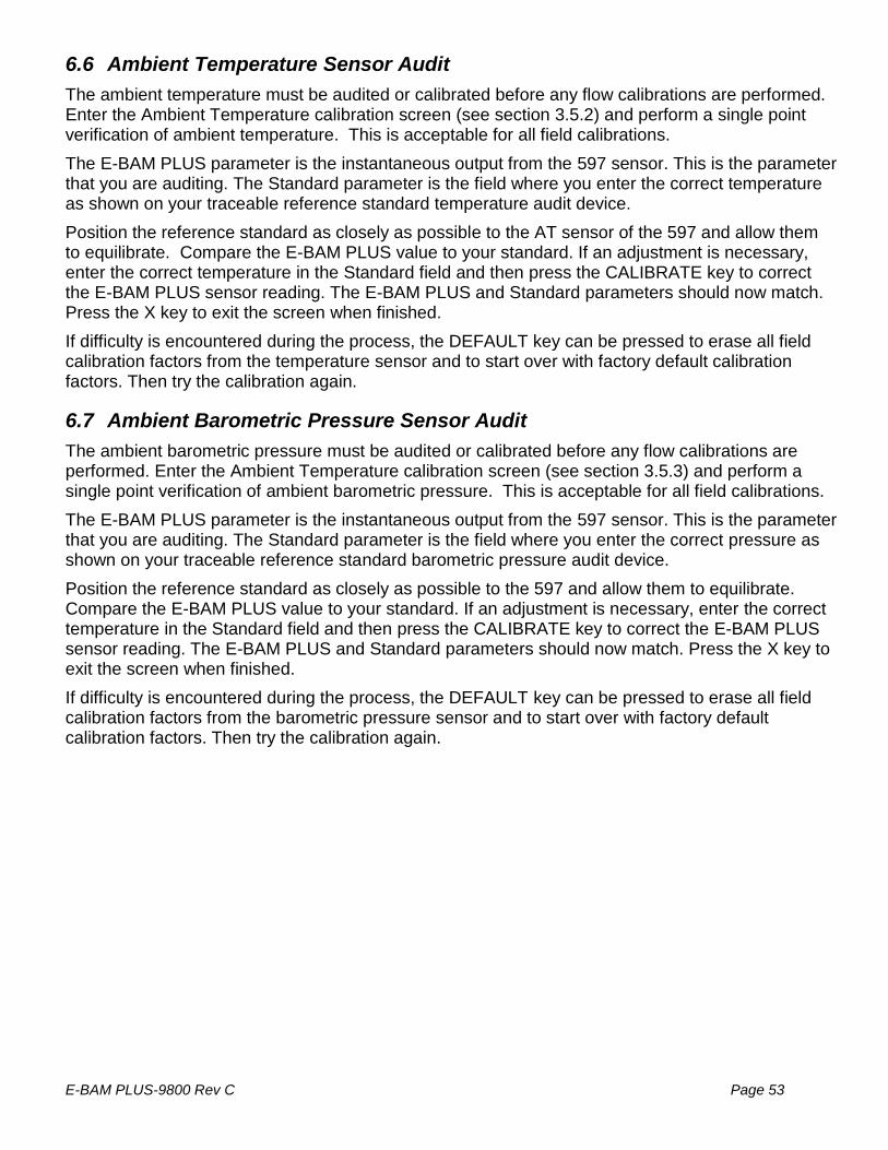
E-BAM PLUS-9800 Rev C Page 53
6.6 Ambient Temperature Sensor Audit
The ambient temperature must be audited or calibrated before any flow calibrations are performed. Enter the Ambient Temperature calibration screen (see section 3.5.2) and perform a single point verification of ambient temperature. This is acceptable for all field calibrations.
The E-BAM PLUS parameter is the instantaneous output from the 597 sensor. This is the parameter that you are auditing. The Standard parameter is the field where you enter the correct temperature as shown on your traceable reference standard temperature audit device.
Position the reference standard as closely as possible to the AT sensor of the 597 and allow them to equilibrate. Compare the E-BAM PLUS value to your standard. If an adjustment is necessary, enter the correct temperature in the Standard field and then press the CALIBRATE key to correct the E-BAM PLUS sensor reading. The E-BAM PLUS and Standard parameters should now match. Press the X key to exit the screen when finished.
If difficulty is encountered during the process, the DEFAULT key can be pressed to erase all field calibration factors from the temperature sensor and to start over with factory default calibration factors. Then try the calibration again.
6.7 Ambient Barometric Pressure Sensor Audit
The ambient barometric pressure must be audited or calibrated before any flow calibrations are performed. Enter the Ambient Temperature calibration screen (see section 3.5.3) and perform a single point verification of ambient barometric pressure. This is acceptable for all field calibrations.
The E-BAM PLUS parameter is the instantaneous output from the 597 sensor. This is the parameter that you are auditing. The Standard parameter is the field where you enter the correct pressure as shown on your traceable reference standard barometric pressure audit device.
Position the reference standard as closely as possible to the 597 and allow them to equilibrate. Compare the E-BAM PLUS value to your standard. If an adjustment is necessary, enter the correct temperature in the Standard field and then press the CALIBRATE key to correct the E-BAM PLUS sensor reading. The E-BAM PLUS and Standard parameters should now match. Press the X key to exit the screen when finished.
If difficulty is encountered during the process, the DEFAULT key can be pressed to erase all field calibration factors from the barometric pressure sensor and to start over with factory default calibration factors. Then try the calibration again.
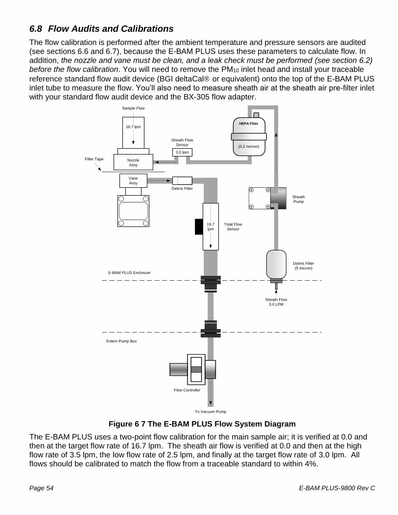
Page 54 E-BAM PLUS-9800 Rev C
6.8 Flow Audits and Calibrations
The flow calibration is performed after the ambient temperature and pressure sensors are audited (see sections 6.6 and 6.7), because the E-BAM PLUS uses these parameters to calculate flow. In addition, the nozzle and vane must be clean, and a leak check must be performed (see section 6.2) before the flow calibration. You will need to remove the PM10 inlet head and install your traceable
reference standard flow audit device (BGI deltaCal or equivalent) onto the top of the E-BAM PLUS inlet tube to measure the flow. You’ll also need to measure sheath air at the sheath air pre-filter inlet with your standard flow audit device and the BX-305 flow adapter.
Figure 6 7 The E-BAM PLUS Flow System Diagram
The E-BAM PLUS uses a two-point flow calibration for the main sample air; it is verified at 0.0 and then at the target flow rate of 16.7 lpm. The sheath air flow is verified at 0.0 and then at the high flow rate of 3.5 lpm, the low flow rate of 2.5 lpm, and finally at the target flow rate of 3.0 lpm. All flows should be calibrated to match the flow from a traceable standard to within 4%.
Debris Filter
Sheath Flow
Sensor
Total Flow
Sensor
Flow Controller
To Vacuum Pump
Vane
Assy
Nozzle
Assy
Filter Tape
Sample Flow
Sheath
Pump
16.7 lpm
3.0 lpm
19.7
lpm
Extern Pump Box
E-BAM PLUS Enclosure
Sheath Flow
3.0 LPM
HEPA Filter
460134
Debris Filter
(5 micron)
(0.2 micron)
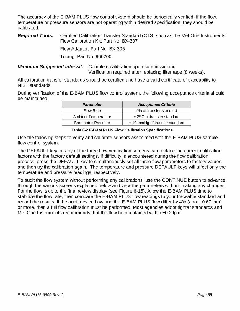
E-BAM PLUS-9800 Rev C Page 55
The accuracy of the E-BAM PLUS flow control system should be periodically verified. If the flow, temperature or pressure sensors are not operating within desired specification, they should be calibrated.
Required Tools: Certified Calibration Transfer Standard (CTS) such as the Met One Instruments Flow Calibration Kit, Part No. BX-307
Flow Adapter, Part No. BX-305
Tubing, Part No. 960200
Minimum Suggested Interval: Complete calibration upon commissioning. Verification required after replacing filter tape (8 weeks).
All calibration transfer standards should be certified and have a valid certificate of traceability to NIST standards.
During verification of the E-BAM PLUS flow control system, the following acceptance criteria should be maintained.
Parameter Acceptance Criteria
Flow Rate 4% of transfer standard
Ambient Temperature ± 2º C of transfer standard
Barometric Pressure ± 10 mmHg of transfer standard
Table 6-2 E-BAM PLUS Flow Calibration Specifications
Use the following steps to verify and calibrate sensors associated with the E-BAM PLUS sample flow control system.
The DEFAULT key on any of the three flow verification screens can replace the current calibration factors with the factory default settings. If difficulty is encountered during the flow calibration process, press the DEFAULT key to simultaneously set all three flow parameters to factory values and then try the calibration again. The temperature and pressure DEFAULT keys will affect only the temperature and pressure readings, respectively.
To audit the flow system without performing any calibrations, use the CONTINUE button to advance through the various screens explained below and view the parameters without making any changes. For the flow, skip to the final review display (see Figure 6-15). Allow the E-BAM PLUS time to stabilize the flow rate, then compare the E-BAM PLUS flow readings to your traceable standard and record the results. If the audit device flow and the E-BAM PLUS flow differ by 4% (about 0.67 lpm) or more, then a full flow calibration must be performed. Most agencies adopt tighter standards and Met One Instruments recommends that the flow be maintained within ±0.2 lpm.

Page 56 E-BAM PLUS-9800 Rev C
1. Allow the calibration transfer standard (CTS) and the E-BAM PLUS to equilibrate to ambient conditions.
2. Go to the Operate menu and select Stop Sample to stop the current sample.
3. Remove the size selective inlet(s) from the sample tube.
4. Remove the internal flow system cover to expose the various flow filters and sheath air pre-filter inlet.
Figure 6-10 Flow System Cover Removed
5. Enter the Test > Ambient Temperature screen.
6. Compare the E-BAM PLUS temperature measurement and CTS temperature reading.
a. If the E-BAM PLUS temperature sensor meets the criteria listed in Table 6-2, go to step 7.
b. If the temperature needs to be adjusted, press the green bordered value box and the numerical entry keypad will be displayed. Enter the CTS temperature value in the Standard field, and press OK to return to the Ambient Temperature screen. Press the grey CALIBRATE button to enter the new calibration offset.
7. Return to the TEST menu and go to the Ambient Pressure screen.
8. Compare the E-BAM PLUS pressure measurement and CTS pressure reading.
a. If the E-BAM PLUS pressure sensor meets the criteria listed in Table 6-2, go to step 9.
b. If the pressure needs to be adjusted, press the green bordered value box and the numerical entry keypad will be displayed. Enter the CTS pressure value in the Standard field, and press OK to return to the Ambient Pressure screen. Press the grey CALIBRATE button to enter the new calibration offset.
9. Return to the TEST menu and go to the Flow Calibration screen.
10. The first screen is for verifying the sample and sheath flows indicate zero flow when a no flow condition exists. Wait until both the sample and sheath values read 0.0 (this could take up to a minute if the pump was recently running) and then press the CONTINUE key to turn on the pump and move to the sheath air flow calibration screen. If 0.0 cannot be achieved, press the grey ZERO button to manually set both values to zero.

E-BAM PLUS-9800 Rev C Page 57
Figure 6-11 Zero Calibrate Screen and Sheath Air Pre-Filter Inlet Tubing Installation
11. Install one end of the 960200 adapter tubing to the sheath air pre-filter inlet (as shown in Figure 6-11) and the other end to the BX-305 fitting (see Figure 6-12).
Figure 6-12 Connecting the CTS to the Sheath Air Pre-Filter Inlet
12. Insert the short adapter of the BX-305 and then install the CTS as shown in Figure 6-12 and then press the grey CONTINUE button to advance to the Sheath Air calibration screen. The pump should start and adjust flow to 3.0 lpm.
CAUTION: It is important that the main sample inlet be free of all obstructions during this test. Any restrictions will affect the flow rate of the sheath air and will result in an inaccurate flow calibration.
Figure 6-13 Sheath Air Calibration Screens
13. The Sheath Air calibration consists of low, high, and target flow rate points (see Figure 6-13). Press the green bordered Set Point field and select 2.5 (the low flow rate) and then press the grey OK button to return to the Flow Calibration screen.
14. The Set Point field should now read 2.5; this is the current flow rate being tested. The E-BAM PLUS field is the current sheath air flow sensor reading. It should be changing as the E-

Page 58 E-BAM PLUS-9800 Rev C
BAM PLUS attempts to lower the flow rate to the new goal. Allow the flow sufficient time to stabilize (it could take a few minutes).
15. Press the green bordered Standard field and the numerical entry keypad will be displayed. Enter the CTS flow value and press OK to return to the Flow Calibration screen.
16. Press the grey SET button. This will temporarily set the low flow point without changing the flow calibration of the monitor. This button should be pressed even if no changes are made.
17. Do not press the grey CONTINUE button at this time. Press the green bordered Set Point field and select 3.5 (the high flow rate) and then press the grey OK button to return to the Flow Calibration screen.
18. The Set Point field should now read 3.5. The E-BAM PLUS field should be changing as the monitor attempts to raise the flow rate to the new goal. Allow the flow sufficient time to stabilize (it could take a few minutes).
19. Press the green bordered Standard field and the numerical entry keypad will be displayed. Enter the CTS flow value and press OK to return to the Flow Calibration screen.
20. Press the grey SET button. This will temporarily set the high flow point without changing the flow calibration of the monitor. This button should be pressed even if no changes are made.
21. Do not press the grey CONTINUE button at this time. Press the green bordered Set Point field and select 3.0 (the target flow rate) and then press the grey OK button to return to the Flow Calibration screen.
22. The Set Point field should now read 3.0. The E-BAM PLUS field should be changing as the monitor attempts to lower the flow rate to the target goal. Allow the flow sufficient time to stabilize (it could take a few minutes).
23. Press the green bordered Standard field and the numerical entry keypad will be displayed. Enter the CTS flow value and press OK to return to the Flow Calibration screen.
24. Press the grey CALIBRATE key. This will permanently set the instrument’s flow calculation.
25. Press the grey CONTINUE key to proceed to the sample air flow calibration (see Figure 6-15).
26. Remove the CTS, the BX-305, and the adapter tubing from the sheath air pre-filter inlet.
27. Install the CTS on the main sample inlet tube as shown in Figure 6-14.

E-BAM PLUS-9800 Rev C Page 59
Figure 6-14 Installing the CTS on the Main Sample Inlet
28. The expected target value for the sample air is 16.7. This is indicated in the Set Point field. The E-BAM PLUS field is the current sample air flow sensor reading. The Standard field is the field where you enter the correct flow as shown on your traceable reference standard if the E-BAM PLUS flow needs to be adjusted.
CAUTION: It is important that both sheath air inlet be free of all obstructions during this test. Any restrictions will affect the flow rate of the main sample air and will result in an inaccurate flow calibration.
Allow the flow sufficient time to stabilize (it could take a few minutes), verify the slow meets the criteria listed in Table 6-2, and enter any corrections needed. Press the CALIBRATE key to set any changes. The E-BAM PLUS and Standard fields should now match.
Figure 6-15 Main Sample Air Calibration and Final Review Screens
29. Press the CONTINUE key to continue on to the flow review screen shown in Figure 6-15. The final screen shows the current measured values for the sample (INLET) and sheath air flows.
30. Press the EXIT key to return to the Test Menu

Page 60 E-BAM PLUS-9800 Rev C
31. Return to the Main Operating Screen, remove the CTS from the inlet tube, and replace the size selective inlet(s).
32. Resume normal sampling operations
6.9 Span Mass Audit
The Mass Audit screen, located in the Test menu, is used to verify the performance of the E-BAM PLUS beta attenuation system. A zero and span foil (included in the E-BAM PLUS accessory kit) will be required to complete this procedure. When this screen is accessed, the vane will be lowered and you will be instructed to enter the zero calibration foil.
The filter tape must be loaded for this test! Insert the zero foil above the filter tape between the nozzle and vane, with the label facing up as shown in Figure 6-16. Note that the membrane is keyed and can only be inserted one way. Take care to minimize tape movement. When the zero foil is detected, the vane will automatically raise up to the foil and the four minute measurement will commence.
Figure 6-16 Starting the Zero Test
After four minutes, the vane will be lowered and the screen will instruct you to remove the zero foil. Remove the zero foil, taking care to minimize tape movement.
Figure 6-17 Completing the Zero Test
Once removed, the display will change to list the current span foil setting as shown in Figure 6-17. Compare this value to the value written on your span membrane tool. If the values do not match, tap the green bordered span value field and enter the value listed on the span tool. Press the grey CONTINUE button to continue to the next step.
The display will instruct you to insert the span foil. Insert the span foil above the filter tape, with the label facing up as shown in Figure 6-18. Note that this membrane is also keyed and can only be inserted one way. Take care to minimize tape movement. When the span foil is detected, the vane will automatically raise up to the foil and the four minute measurement will commence.
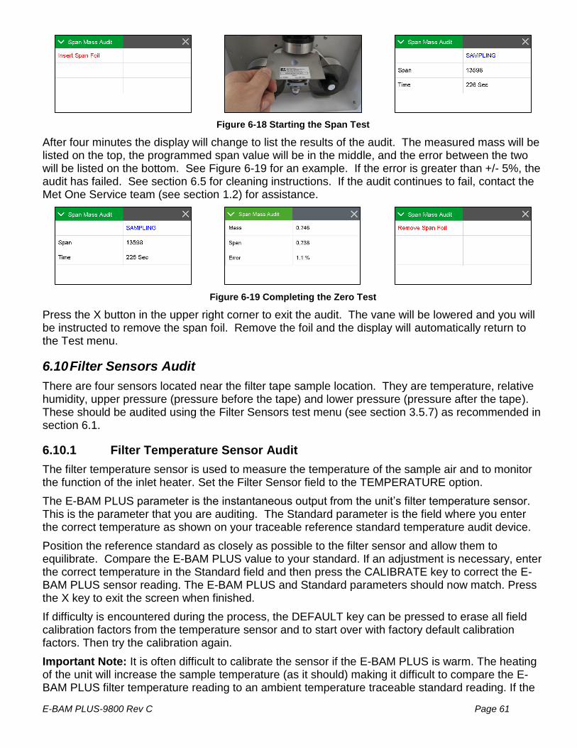
E-BAM PLUS-9800 Rev C Page 61
Figure 6-18 Starting the Span Test
After four minutes the display will change to list the results of the audit. The measured mass will be listed on the top, the programmed span value will be in the middle, and the error between the two will be listed on the bottom. See Figure 6-19 for an example. If the error is greater than +/- 5%, the audit has failed. See section 6.5 for cleaning instructions. If the audit continues to fail, contact the Met One Service team (see section 1.2) for assistance.
Figure 6-19 Completing the Zero Test
Press the X button in the upper right corner to exit the audit. The vane will be lowered and you will be instructed to remove the span foil. Remove the foil and the display will automatically return to the Test menu.
6.10 Filter Sensors Audit
There are four sensors located near the filter tape sample location. They are temperature, relative humidity, upper pressure (pressure before the tape) and lower pressure (pressure after the tape). These should be audited using the Filter Sensors test menu (see section 3.5.7) as recommended in section 6.1.
6.10.1 Filter Temperature Sensor Audit
The filter temperature sensor is used to measure the temperature of the sample air and to monitor the function of the inlet heater. Set the Filter Sensor field to the TEMPERATURE option.
The E-BAM PLUS parameter is the instantaneous output from the unit’s filter temperature sensor. This is the parameter that you are auditing. The Standard parameter is the field where you enter the correct temperature as shown on your traceable reference standard temperature audit device.
Position the reference standard as closely as possible to the filter sensor and allow them to equilibrate. Compare the E-BAM PLUS value to your standard. If an adjustment is necessary, enter the correct temperature in the Standard field and then press the CALIBRATE key to correct the E-BAM PLUS sensor reading. The E-BAM PLUS and Standard parameters should now match. Press the X key to exit the screen when finished.
If difficulty is encountered during the process, the DEFAULT key can be pressed to erase all field calibration factors from the temperature sensor and to start over with factory default calibration factors. Then try the calibration again.
Important Note: It is often difficult to calibrate the sensor if the E-BAM PLUS is warm. The heating of the unit will increase the sample temperature (as it should) making it difficult to compare the E-BAM PLUS filter temperature reading to an ambient temperature traceable standard reading. If the

Page 62 E-BAM PLUS-9800 Rev C
sensor is to be calibrated, it is best to do it when the E-BAM PLUS is cold (equilibrated to ambient) and the vane is lowered. It is recommended to leave the sensor at the factory default calibration. The E-BAM PLUS filter temperature sensor very rarely fails.
6.10.2 Relative Humidity Sensor Audit
The filter relative humidity sensor is used to measure the humidity of the sample air and to control the inlet heater to prevent moisture from being sampled as particulate mass. Set the Filter Sensor field to the HUMIDITY option.
The E-BAM PLUS parameter is the instantaneous output from the unit’s filter internal relative humidity (RH) sensor. This is the parameter that you are auditing. The Standard parameter is the field where you enter the correct RH as shown on your traceable reference standard RH audit device.
Position the reference standard as closely as possible to the filter sensor and allow them to equilibrate. Compare the E-BAM PLUS value to your standard. If an adjustment is necessary, enter the correct RH in the Standard field and then press the CALIBRATE key to correct the E-BAM PLUS sensor reading. The E-BAM PLUS and Standard parameters should now match. Press the X key to exit the screen when finished.
If difficulty is encountered during the process, the DEFAULT key can be pressed to erase all field calibration factors from the RH sensor and to start over with factory default calibration factors. Then try the calibration again.
Important Note: It is often difficult to calibrate the sensor if the E-BAM PLUS is warm, as the heating of the unit will reduce the sample RH (as it should) making it difficult to compare the E-BAM PLUS filter RH reading to an ambient RH traceable standard reading. If the sensor is to be calibrated, it is best to do it when the E-BAM PLUS is cold (equilibrated to ambient) and the vane is lowered. It is recommended to just leave the sensor at the factory default calibration. The E-BAM PLUS filter RH sensor is only a ±4% device when functioning properly, and will typically read a completely unreasonable value if it fails, such as 135% or -25%.
6.10.3 Upper and Lower Pressure Sensors Audit
The upper and lower pressure sensors are used to detect excessive tape loading due to heavy particulate sampling. If the user defined threshold is exceeded, the sample will be suspended and the tape advanced to prevent damage to the pump and the tape itself. See section 3.6.12 for details. To audit these sensors set the Filter Sensor field to the UPPER PRES or LOWER PRES option.
The E-BAM PLUS parameter is the instantaneous output from the unit’s upper or lower pressure sensor, as selected. This is the parameter that you are auditing. The Standard parameter is the field where you enter the correct pressure as shown on your traceable reference standard pressure audit device.
Position the reference standard near the E-BAM PLUS and verify both the standard and the E-BAM PLUS values are stable. Compare the E-BAM PLUS value to your standard. If an adjustment is necessary, enter the correct pressure in the Standard field and then press the CALIBRATE key to correct the E-BAM PLUS sensor reading. The E-BAM PLUS and Standard parameters should now match. Press the X key to exit the screen when finished.
If difficulty is encountered during the process, the DEFAULT key can be pressed to erase all field calibration factors from the selected pressure sensor and to start over with factory default calibration factors. Then try the calibration again.

E-BAM PLUS-9800 Rev C Page 63
Important Note: The pressure sensors must be audited individually and with the pump off. Selecting either pressure sensor for auditing should cause the pump to stop. If it does not, contact the Met One Instruments service department for assistance (see section 1.2).
6.11 Analog Output Audits
If the E-BAM PLUS is used with an external analog data logger, then the analog voltage output of the E-BAM PLUS must be periodically checked to ensure data integrity. Enter the Analog Output Test menu (see section 3.5.12). The screens shown in Figure 6-20 are for an analog output configuration of 0.000-5.000 VDC and 0-1,000 μg/m3. The following audit discussion will assume these values are selected for ease of explanation.
Figure 6-20 The E-BAM PLUS Analog Output Test Screens
The Conc Output field specifies the desired concentration level to test. When this test screen is first entered, the Conc Output will be set to minimum scale. In this example, that is 0 but if the range were offset to something like -15 to +985 μg/m3, then this field would be set to -15 instead. Verify that the voltmeter reads 0.000 VDC on the analog output wiring. Confirm that the connected data logger also reads either 0.000 VDC or the minimum concentration value of 0 μg/m3.
Next, set the Conc Output value to the full scale setting (1,000 μg/m3). Verify the voltmeter reads the expected full scale voltage value of 5.000 VDC on the analog output wiring. Confirm the data logger also reads either 5.000 VDC or the maximum concentration value of 1,000 μg/m3.
Finally, select at least one test value somewhere between the minimum and maximum concentrations. In Figure 6-21, a value of 500 μg/m3 was selected. This represents ½ of the full scale value of 1,000 μg/m3 so it would be expected to see 50% of the full scale voltage output. For the 5.000 VDC range, that is 2.500 VDC. Multiple points may be verified to comply with local requirements.
Setting the Conc Output to a value outside of the defined range will result in the Max Out or Min Out being clamped at the full scale or minimum scale value displayed. In Figure 6-22, the final image shows a value of 1,005 μg/m3 was selected. This setting exceeds the maximum range value of 1,000 μg/m3, so the Set Out field is set to the Max Out value instead of 5.025 VDC.
If a voltage or concentration range is used that is not 0-5.000 VDC or 0-1,000 μg/m3, the values for this audit will differ from what is stated above. For example, if the range were 0.000-1.000 VDC for -15 to +985 μg/m3, then the maximum voltage output would be 1.000 VDC instead of 5.000 VDC and the maximum concentration would be 985 μg/m3 instead of 1,000 μg/m3. Similarly, the 50% scale value would not be 500 μg/m3 at 2.500 VDC, but instead 485 μg/m3 at 0.500 VDC. Any voltage and concentration range combination that meets local requirements may be used.
Notes About the Analog Output Tests: Only a high quality voltmeter should be used for this test. Cheap voltmeters usually do not give accurate measurements at millivolt levels. The E-BAM PLUS analog output should also be checked with the external data logger connected, in order to make sure that the logger or cables are not affecting the voltage. The E-BAM PLUS analog outputs have their own connection on the bottom of the case. See Figure 2-6 and

Page 64 E-BAM PLUS-9800 Rev C
Figure 2-8 for location and pin out details. If a replacement analog output cable is needed, contact the Met One Service department (see section 1.2).

E-BAM PLUS-9800 Rev C Page 65
6.12 E-BAM PLUS Error Displays, Error Logs, and Error Codes
This section provides information about routine maintenance of the E-BAM PLUS, and for performing more detailed diagnostic tests if a problem is encountered. The E-BAM PLUS often generates error messages on the display or in the data log if a failure or other problem is detected. Many times there is a simple solution, but persistent errors often signify a failure which will require investigation. The E-BAM PLUS error codes are described in this section.
In the event a measured parameter or sequence is not within design specifications, the E-BAM PLUS will generate an alarm. These alarms can be monitored via the alarm log, output files or the alarm relay. A list of alarms is detailed in Table 6-3.
Code Description Cause
1 Tape Break No tape movement was detected during the tape move process.
2 Beta Detector The event occurs when the Beta detector count rate is less than 500 Hz during the sampling cycle.
4 Sensor Range The event occurs when an analog sensor reading (AT, RH, BP, UPPER, LOWER, FT, FRH) is outside the designated limits.
8 Tape Advance The event occurs when the pressure drop across the tape exceeded the Tape Advance Pressure setting.
16 Flow Failure
The event occurs when the total flow or sheath flow is less than 1.0 LPM for greater than 1 minute.
The event occurs when the sample flow is +/-10% out of regulation for 1 minute.
The event occurs when the sample flow is +/-5% out of regulation for 5 minutes.
32 Vane Failure
The event occurs when the vane failed to move and stop at the up or down position.
The event will also will occur when the foil device is still inserted at start of operation.
64 Digital Link Failure
The event occurs when communication with the 597 sensor has ceased for greater than 10-seconds.
128 Power Failure The event occurs for a power cycle or a micro-processor reset.
256 Short Sample The event occurs when the first sample cycle is less than 1-hour.
512 Maintenance The event occurs when the user stops normal operation.
Table 6-3 The E-BAM PLUS Alarm Conditions
An alarm is indicated and logged at the time it occurs. The resolution time is not recorded. See section 3.7 for an explanation of viewing alarms through the E-BAM PLUS panel display.
Note: If multiple errors or alarms occur in the same data period, then the logged alarm code will be the sum of the two individual code numbers. This is a rare occurrence.

Page 66 E-BAM PLUS-9800 Rev C
6.13 E-BAM PLUS Hardware Failure Screen
This screen is presented to the user when a hardware failure occurs with the type of alarm (Tape Break, Sensor Range, Flow Failure, etc.) indicated in red text. Pressing the grey ALARMS button will present the View Alarms screen. See section 3.7 for more information about viewing alarms.
Figure 6-23 Sample Alarm Screen
6.13.1 Sensor Out of Range Event
The sensor outside range alarm event occurs when one of the E-BAM PLUS sensors is reading outside of its designated limit. Each sensor, along with its upper and lower range limits, is shown in Table 6-4. The Stop column indicates whether or not the error will cause the E-BAM PLUS to stop sampling.
Sensor Minimum Maximum Stop
AT -50 70 Yes
RH 0 100 No
BP 375 825 Yes
UPPER 228 818 Yes
LOWER 228 818 Yes
FT -40 60 Yes
FRH 0 98.9 No
BOX -40 60 No
BETA 500 20000 Yes
Table 6-4 Sensor Ranges
6.14 Alarm Relay
There is one alarm relay on the E-BAM PLUS to indicate to an external device that an alarm has occurred. It is a normally open (NO) contact that closes whenever there is an alarming condition.
The short sample and tape advance alarms do not affect the alarm relay. See section 3.5.14 for testing details.

E-BAM PLUS-9800 Rev C Page 67
6.15 Basic Problem and Cause/Solution Table
The following table contains information on some of the more common problems that may be encountered, and some steps to identify and remedy the problems. Met One Instruments welcomes customer suggestions for new items to include in this section of future manual revisions. If the solution cannot be found in the following table, then contact one of our expert service technicians for help in resolving your problem.
Problem: The mass monitor won’t start a measurement cycle.
Cause/Solution: • The mass monitor will not start a measurement cycle if it detects a hardware failure, such as low beta count signal, pressure sensor failure, or pump failure.
• The mass monitor will not start a cycle if either the zero membrane plate or the shipping shim is inserted.
• The mass monitor will not start a cycle if the 597 sensor is not connected.
• The mass monitor will not start a cycle if the filter tape is not installed correctly.
• The mass monitor will usually display an error message on the display if it cannot start a cycle.
• If the mass monitor is left in a SETUP or FIELD CALIBRATION screen, it should still try to start a cycle after several minutes of inactivity, unless a failure is detected.
Problem: The analog output voltage concentration readings are full-scale.
Cause/Solution: • The mass monitor will force the analog output to the full scale voltage to indicate an error. Review the History / Alarm log to view any possible errors.
• If the configured full-scale analog output is recorded by a connected external data logger, then either there is an error in the mass monitor, or the particulate concentrations have exceeded the range of the analog output.
Problem: The mass monitor records frequent “Pressure Drop Excessive” errors.
Cause/Solution: • This usually indicates that the filter tape is automatically advancing in response to being clogged due to heavy particulate loading.
• If frequent pressure-drop errors are encountered, try setting the TAPE ADVANCE setting to a shorter interval. See section 3.6.12. When hourly PM readings are high, more frequent tape advance intervals may be required.
Problem: The concentration indicates negative values.
Cause/Solution: • It is possible for the mass monitor to occasionally record negative hourly values if the actual particulate concentration is extremely low. This is because the mass monitor has an hourly random noise band of several micrograms.
• The real-time averages of the mass monitor (especially the 1 and 5 minute averages) are considerably noisier than the hourly measurements. These noise spikes may indicate negative concentrations unless the true concentrations are high.
• The noise performance of the mass monitor may be audited. Met One Instruments supplies the BX-302 zero filter kit for auditing the zero readings of the mass monitor.

Page 68 E-BAM PLUS-9800 Rev C
Problem: The airflow won’t regulate at the correct rate of 16.7 lpm.
Cause/Solution: • This usually indicates that the air pump is losing vacuum capacity due to wear.
• Check for leaks at the nozzle. This will often cause the inlet flow to be low even though the flow sensor is measuring the correct flow rate. This is because the flow sensor is downstream of the filter tape and nozzle. Clean the nozzle and vane.
• Perform a flow calibration. If the flow regulates at the lower calibration point, but not the higher point, the pump is probably worn out or there is a leak.
• The grey plastic pump muffler used on the vacuum pump clogs up after several months. Replace it every six months.
• Check the inlet and PM heads for obstructions.
Problem: The mass monitor has flow leaks, even after cleaning the nozzle and vane.
Cause/Solution: • The vane may be sticking. Verify that the vane up/down motion is smooth and complete. If the vane movement is sticky or gritty, it will not seal properly.
• Check the O-rings on the sharp-cut cyclone (if used). These frequently leak.
• Check for bad O-rings on the inlet receiver.
• Check all of the push-in air fittings throughout the air flow system.
Problem: The mass monitor will not pass the span membrane test.
Cause/Solution: • This often just indicates the membrane foil surface is dirty or damaged. It can be cleaned with distilled water. Damaged membranes must be replaced.
• If the membrane is in good condition, but the mass monitor fails span tests, then the most common problem is debris on the beta detector window. Carefully blow through the vane with canned dusting air to blow debris off of the detector window and try again.
• If the detector is clean and the membrane is in good condition, then failed span tests can indicate that the detector is wearing out. Contact the Service Department.
Problem: The clock settings are lost when the mass monitor is powered down.
Cause/Solution: • There is a lithium coin cell battery inside the mass monitor that maintains the clock when the mass monitor is powered off. The battery may need to be replaced if the clock resets when the mass monitor is powered off.

E-BAM PLUS-9800 Rev C Page 69
7 DATA RETRIEVAL and COMMUNICATIONS
The E-BAM PLUS is capable of relaying information to and from external devices using analog outputs, digital inputs and outputs, RS-232 serial communications, USB serial, Ethernet and USB flash drive.
7.1 Analog Voltage Output
Cable connections on the bottom panel of the E-BAM PLUS are available for communicating with data acquisitions system by means of analog and digital inputs and outputs.
The E-BAM PLUS analog output can be set to 0-1, 0-2.5, or 0-5 volts, which represents a 1,000 µg concentration range. See Section 3.6.9 for details about how to set up and configure the various analog output scales and Section 6.11 for instructions about how to test the output voltage.
Figure 7-1 E-BAM PLUS Serial Cable Wiring, (with Analog Output)
The pump box cable connects to the PUMP BOX POWER port.
The optional wind sensor (see section 10.2) connects to the WS/WD SENSOR port.
The Alarm Relay output is rated for 1 A at 125 VAC or 60 VDC maximum.
Analog outputs 1 and 2 are connected to the ANALOG OUTPUT port.
The 597 Digital Sensor connects to the 597 SENSOR port.
The optional Airsis Satellite link (see section 10.1) connects to the CLOUD SERIAL port.
All other serial outputs use the RS-232 SERIAL port.
7.2 Transfer Data to USB Flash Drive
The E-BAM PLUS can copy data files directly to a user-supplied USB flash drive. This drive must be installed in the USB port located on the right hand side of the tape transport plate inside the monitor. This USB port is not used for any other purpose.

Page 70 E-BAM PLUS-9800 Rev C
Figure 7-2 Data Transfer Interface Screens
1. Enter the Operate > Transfer Data menu.
a. The Days field determines how many records you download. If you wish to change the number of days being copied, press the green bordered value box and the numerical entry keypad will be displayed. Enter the number of days between 001 and 999.
b. The FILES field determines whether you download all of the stored record types or only the user selected records. The USER files are ones which are used for all routine data collection purposes. The ALL option includes additional factory diagnostics files which are only used if data is being sent to Met One Instruments for factory support. The default setting is USER. If you need to change this field, press the green bordered value box and a list of the options available will be displayed. Tap the one you wish to use and it will be applied.
2. Locate the USB slot above the tape take up spool and insert a USB memory stick into it.
3. Press the grey COPY button to copy the selected data to the USB memory stick. When the COPY COMPLETE message is displayed, remove the USB memory stick and close the front door of the E-BAM PLUS.
7.3 Comet™ Data Retrieval Software
The E-BAM PLUS is supplied with a CD containing a free copy of the Comet™ program, which is a simple Windows-based communications terminal program developed by Met One Instruments. This is the recommended method for all E-BAM PLUS data retrieval, since Comet allows the user to easily download the data logs, error logs, and settings (EEPROM) files from the E-BAM PLUS without the user having to know any of the underlying communications protocols. The Comet CD also contains a very comprehensive pdf user’s manual for the program. Install the program onto the computer that you will be using for data retrieval, and review the manual for complete data examples.
Note: If you use Comet for E-BAM PLUS data retrieval, you will not need to use any of the terminal program setups or “AutoMet” commands shown in the following sections of this manual.
7.4 Downloading Data Using HyperTerminal or other Terminal Programs
The E-BAM PLUS is able to communicate via serial commands using RS-232, USB Serial, or Ethernet. The monitor only allows one of these connections at a time. These connections allow users to both download data and operate the instrument
The default RS-232 settings are as follows:
Baud Rate: 9600 Data Bits: 8

E-BAM PLUS-9800 Rev C Page 71
Parity: None Stop Bits: 1 Flow Control: None (should be set to CTS/RTS only when using Ethernet communications)
7.4.1 User Communication
In the User Communication (or Terminal) mode, commands are issued by entering a letter or number command and then pressing the Enter, <cr>, key. The <Esc> key is not used when sending commands in this mode.
Press the Enter key three times to enter User Communication mode. An asterisk character appears confirming you have entered the mode and that the instrument is ready for a new command. Commands will be echoed back from the instrument and an asterisk will appear after a command has completed.
COMMAND DESCRIPTION
1 Request settings report
2 Request All data report
3 Request New data report
4 Request Last data report
7 Request alarm event report
C Clear data log file – $
D Get/Set date part of the real time clock – $
H Help menu
Q Quit and exit terminal mode
T Get/Set time part of the real time clock
DT Get/Set the date and time of the real time clock
ID Get/Set location ID or address
OI Get/Set output interval
QH Report current readings header
RQ Report current readings without header
RV Report Model/Part/Revision
SS Get Met One serial number
Table 7-1 Common Serial Command Set
To issue one of the commands listed in Table 7-1, type the command listed and press the Enter key. The command will run and display the requested information or current setting, as appropriate.
For example, to view the current date setting type the letter D followed by the Enter key. The current date will be reported. The sequence would appear like this:
D<cr>
D 2013-01-18<cr><lf>
To change a setting, the typical sequence is to type the command, press the space bar one time, enter the new value in the same format that is displayed when checking the setting, and then pressing the Enter key.

Page 72 E-BAM PLUS-9800 Rev C
Continuing the example above, to change the date setting type the letter D, space, and then the current date in YYYY-MM-DD format followed by the Enter key. A confirmation of the new date will be reported. The sequence would appear like this:
D 2016-02-28<cr>
D 2016-02-28<cr><lf>
Pressing <Esc> or Q<cr> will exit terminal mode.
For a detailed listing of all commands and their formats, consult the E-BAM PLUS 7500 document contained on the CD included with your sampler or contact the Met One Instruments service department. See section 1.2.
7.4.2 Computer Communication
In the Computer Communication mode, character echo is suppressed. This means if you are issuing commands in this mode using a keyboard, you will not see what you are typing displayed on the screen. The command format includes a checksum to verify data integrity.
The mode is entered whenever an <Esc> character is sent to the instrument. Commands are issued using the following format:
<Esc>Cmd p1 p2*cs<cr>
Computer commands are prefaced with an <Esc> character followed directly by a command (Cmd).. After the command there can be zero or more parameter field (p1 and p2) where each field is separated by a space. The end of the message is signaled by the Checksum Delimiter character (*) followed by the checksum itself (cs). Finally, the command is terminated with a carriage return (<cr>).
A computer command example requesting the Model/Part/Revision numbers would look like this:
<Esc>RV*1234<cr>
All command responses are terminated with a checksum. The above command response would have this format:
E-BAM PLUS, 82102, R1.0.0*01402<cr><lf>
CPLD, 81699, R1.0.0*01035<cr><lf>
For a listing of all commands and their formats along with additional in depth Computer Communication details, consult the E-BAM PLUS 7500 document contained on the CD included with your sampler or contact the Met One Instruments service department. See section 1.2.

E-BAM PLUS-9800 Rev C Page 73
8 ACCESSORIES and PARTS
8.1 Consumables, Replacement Parts, and Accessories
The following parts are available from Met One for maintenance, replacement, service, and upgrades. If unsure about a part you need, please contact the Service department. Some of these parts require technical skills or special considerations before use or installation.
Description Part Number Graphic
Consumables
Filter Tape Roll, Glass Fiber, 30 mm x 21 m 460180
Filter Tape Core Tube, Grey Plastic 8150
Cotton-Tipped Applicators, nozzle cleaning, 100 pack Solon #362
995217
0.2 Micron Sheath Air Filter 460182
5 Micron Filter (Used for the Sheath Air Pre-Filter and Flow Sensor Debris Filter
580345
O-Ring, Nozzle, 1 required 720066
O-Ring, Inlet Tube Receiver, 4 required 720069
O-Ring Kit, for BX-807 Cyclone, set of 6 720097
O-Ring Kit, for BX-802 PM10 Head, set of 3 8965
Tools
Zero Filter Calibration Kit, with valve Same as BX-305 but with 0.2 micron filter
BX-302
Volumetric Flow Calibration Kit (BGI deltaCal™) Flow, Temp, and Pressure Reference Standards Met One recommended flow audit meter
BX-307

Page 74 E-BAM PLUS-9800 Rev C
Flow System Components
E-BAM PLUS External Pump Option, 115 VAC EX-225
E-BAM PLUS External Pump Option, 230 VAC EX-226
Flow Sensor, Mass, 0-200 LPM, Internal Assembly 970611
Filter RH Sensor, Replacement Only 8624
Filter Temperature Sensor, Replacement Only 8131
Inlet Components
PM10 Inlet Head, EPA Specified BX-802
TSP Sampling Inlet Cap, Harsh Environment with insect screen and rain cap
BX-803
PM2.5 Sharp Cut Cyclone BX-807
PM2.5 WINS Impactor BX-804
FRM Inlet Tube, E-BAM PLUS, Aluminum, 10 inches 81183 See Figure 8-1
Cross-arm Clamp, ¾” x ¾”, Aluminum Mounts cross-arms to the E-BAM PLUS tripod
1552

E-BAM PLUS-9800 Rev C Page 75
Meteorological Sensors
Combination Sensor for Ambient Temperature, Relative Humidity, and Barometric Pressure Standard E-BAM PLUS Accessory
597
Analog Wind Speed and Wind Direction Combination Sensor for use with E-BAM PLUS
EX-MSO
Sonic Wind Speed and Wind Direction Combination Sensor for use with E-BAM PLUS
EX-AIO
Miscellaneous Accessories
Gear Motor Assembly Used for vane and tape reel
81598
Tripod Assembly, E-BAM PLUS/E-SAMPLER EX-905
Tape Spool Cover, Replacement, 2 per unit 82148
External Serial Cable Assembly with DB-9 Connector 82165
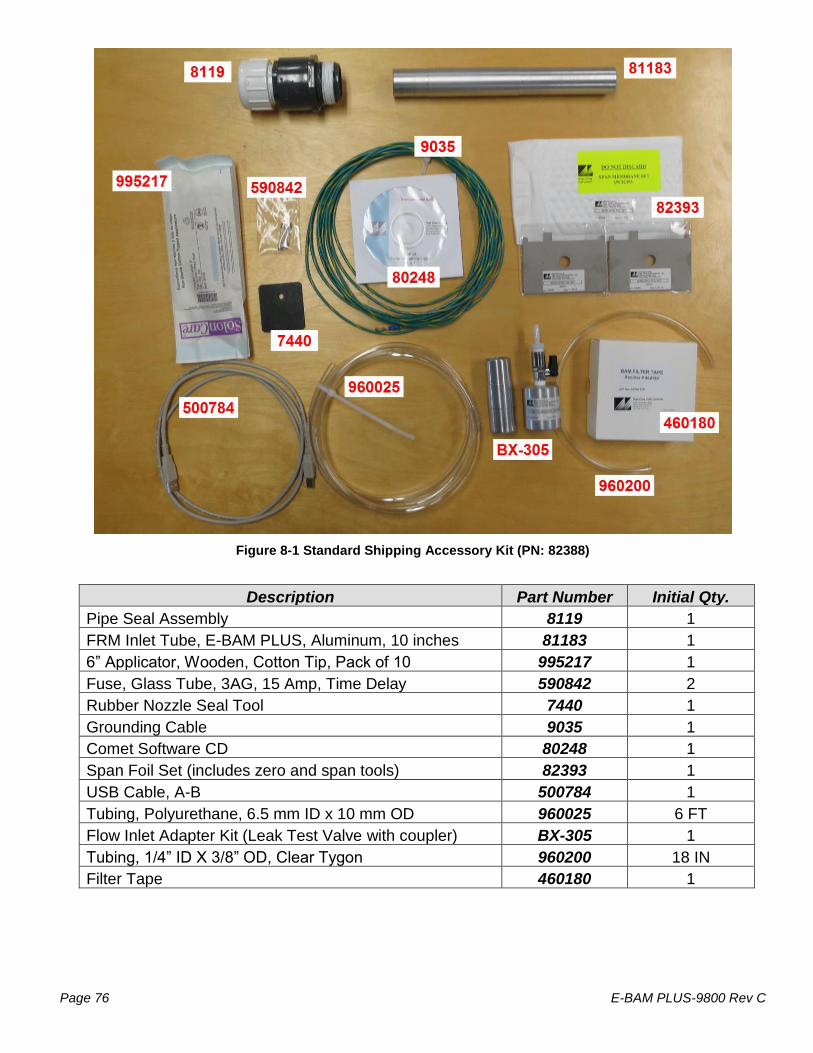
Page 76 E-BAM PLUS-9800 Rev C
Figure 8-1 Standard Shipping Accessory Kit (PN: 82388)
Description Part Number Initial Qty.
Pipe Seal Assembly 8119 1
FRM Inlet Tube, E-BAM PLUS, Aluminum, 10 inches 81183 1
6” Applicator, Wooden, Cotton Tip, Pack of 10 995217 1
Fuse, Glass Tube, 3AG, 15 Amp, Time Delay 590842 2
Rubber Nozzle Seal Tool 7440 1
Grounding Cable 9035 1
Comet Software CD 80248 1
Span Foil Set (includes zero and span tools) 82393 1
USB Cable, A-B 500784 1
Tubing, Polyurethane, 6.5 mm ID x 10 mm OD 960025 6 FT
Flow Inlet Adapter Kit (Leak Test Valve with coupler) BX-305 1
Tubing, 1/4” ID X 3/8” OD, Clear Tygon 960200 18 IN
Filter Tape 460180 1

E-BAM PLUS-9800 Rev C Page 77
9 THEORY OF OPERATION and MATHEMATICAL ANALYSIS When the high-energy electrons emanating from the radioactive decay of 14C (carbon-14) interact with nearby matter they lose their energy and, in some cases, are absorbed by the matter. These high-energy electrons emitted through radioactive decay are known as beta rays and the process is known as beta-ray attenuation. When matter is placed between the radioactive 14C source and a device designed to detect beta rays, the beta rays are absorbed and/or their energy diminished. This results in a reduction in the number of beta particles detected. The magnitude of the reduction in detected beta particles is a function of the mass of the absorbing matter between the 14C beta source and the detector. The number of beta particles passing through absorbing matter, such as dust deposited on a filter tape, decrease nearly exponentially with the mass through which they much pass. Equation 1 shows this relationship.
Equation 1
xeII 0
In Equation 1, I is the measured beta ray intensity (counts per unit time), of the attenuated beta ray (dust laden filter tape), I0 is the measured beta ray intensity of the un-attenuated beta ray (clean
filter tape), is the absorption cross section of the material absorbing the beta rays (cm2/g), and x is the mass density of the absorbing matter (g/cm2). Equation 1 very closely resembles the Lambert-Beers Law, which is used in spectrometric analysis. Just as the Lambert-Beers Law is an idealization of what is actually observed, Equation 1 is also an idealized simplification of the true processes occurring meant to simplify the corresponding mathematics. However, experimental measurement shows that in properly designed monitors, such as the E-BAM PLUS, the use of this equation introduces no substantial error. Equation 1 may be rearranged to solve for x, the mass density of the absorbing matter. This is shown in Equation 2.
Equation 2
x
I
Iln
μ
1
I
Iln
μ
1 0
0
In practice, the absorption cross section is experimentally determined during the calibration process. Once I and I0 are experimentally measured, it is a simple matter to calculate x, the predicted mass density.
In practice, ambient air is sampled at a constant flow rate (Q) for a specified time t. This sampled air is passed through a filter of surface area A. Once x, the mass density of collected particles, has
been determined, it is possible to calculate the ambient concentration of particulate matter (g/m3) with Equation 3.
Equation 3
g
cmΔt(min)μ
min
literQ
)A(cm10
m
μgc
2
26
3

Page 78 E-BAM PLUS-9800 Rev C
In Equation 3, c is the ambient particulate concentration (g/m3), A is the cross sectional area on the tape over which dust is being deposited (cm2), Q is the rate at which particulate matter is being
collected on the filter tape (liters/minute), and t is the sampling time (minutes). Combining these equations yields to the final expression for the ambient particulate concentration in terms of measured quantities. This is shown in Equation 4.
Equation 4
I
Iln
g
cmΔt(min)μ
min
literQ
)A(cm10
m
μgc 0
2
26
3
The key to the success of the beta attenuation monitor is due in part to the fact that , the absorption cross-section, is almost insensitive to the nature of the matter being measured. This makes the E-BAM PLUS very insensitive to the chemical composition of the material being collected. It is instructive to perform a conventional propagation of errors analysis on Equation 4. Doing so,
one can develop an equation for the relative measurement error (c/c) as a function of the uncertainty in each of the parameters comprising Equation 4. This leads to Equation 5.
Equation 5
2
0
2
0
2
I
2
0
2
2
I
2
2
μ
2
2
t
2
2
Q
2
2
Ac
IIlnI
σ
IIlnI
σ
μ
σ
t
σ
Q
σ
A
σ
c
σ0
Inspection of Equation 5 reveals several things. The relative uncertainty of the measurement (c/c) is decreased (improved) by increasing the cross sectional area of the filter tape (A), the flow rate
(Q), the sampling time (t), the absorption cross-section (), I and I0.
In practice, the uncertainty associated with the filter area (A/A), may be minimized by ensuring that the tape is in exactly the same position during the I0 measurement as in the I measurement phase. Careful design of the tape control mechanisms inside of the E-BAM PLUS results in minimal error here.
The uncertainty in the flow rate (Q/Q) may be minimized by properly controlling the flow of the
instrument. This value is on the order of 1%.
The relative error due to the uncertainly in the absorption cross section (/), is due to its slight variation as a function of the chemical composition of the matter being monitored. Generally, this
relative error is on the order of 2-3%, with judicious selection of the calibrated value of . The uncertainty associated with the measurement of I and I0 has to do with the physical nature of the process leading to the emission of beta particles from the decay of 14C. This process follows
Poisson statistics. Poisson statistics show the uncertainty in the measurement of I (I/I) and I0
(I0/I0) are minimized by increasing the sampling time. Mathematical analysis shows that doubling the sampling time and hence the measured intensity of I or I0 will reduce the uncertainty of the measurement by a factor of 1.41 (square root of 2).

E-BAM PLUS-9800 Rev C Page 79
9.1 Converting Data Between EPA Standard and Actual Conditions
As described in this manual, the E-BAM PLUS can obtain concentration data using either actual or standard values for ambient temperature and pressure. In some cases, it is necessary to convert past concentration data collected in standard conditions to actual conditions, or the other way around. Note: temperature is in degrees Kelvin (C+273) and pressure is in mmHg.
Equation 6
Equation 6 can be used to calculate the standard concentration (Cstd) from the ambient concentration (Camb) data using ambient barometric pressure and temperature data (Pamb and Tamb) from the same time period in which the ambient concentration was recorded. Pstd and Tstd are the values of standard barometric pressure and standard ambient temperature. These values are usually the EPA mandated 760 mmHg and 298 degrees Kelvin (25° C). Note: Some other countries use different values for standard temperature and pressure.
Equation 7
Equation 7 can be used to calculate the ambient concentration (Camb) from the standard concentration (Cstd) data using the ambient temperature and pressure. It is necessary to have access to valid data for the ambient temperature and pressure for the desired sample hour in order to be able to make the calculations. Example: You have a data value of 27µg from an E-BAM PLUS which was configured to report data in EPA Standard conditions (298 K and 760 mmHg), but you need to know what the concentration would have been in actual conditions. The actual average temperature for the hour in question was 303 K and the average pressure was 720 mmHg.
Cstd = Camb * (Pstd / Pamb) * (Tamb / Tstd)
Camb = Cstd * (Pamb / Pstd) * (Tstd / Tamb)
Camb = Cstd * (Pamb / Pstd) * (Tstd / Tamb) Camb = 27 * (720/760) * (298/303)
Camb = 27 * 0.9474 * 0.9835
Camb = 25.1 g

Page 80 E-BAM PLUS-9800 Rev C
10 SPECIAL E-BAM PLUS CONFIGURATIONS
The E-BAM PLUS can be supplied in custom configurations or with non-standard accessories in order to meet specific monitoring needs.
10.1 AIRSIS Satellite Uplink Option
The E-BAM PLUS can be equipped with an optional Iridium satellite communications module which can download digital data from the E-BAM PLUS serial port and upload it through a satellite system. The module is designed by AIRSIS specifically for use with the E-BAM PLUS, and mounts directly onto the tripod. The system is widely used for remote deployments.
Contact Met One for details about this configuration.
10.2 Wind Sensor Options
The E-BAM PLUS can be equipped with an optional combination wind speed and direction sensor. There are both analog and sonic type sensors available.
10.2.1 EX-MSO
The EX-MSO sensor provides traditional analog cup and vane wind measurements. It is mounted on a cross-arm assembly as shown in section 2.3 Figure 2-4.
It connects to the E-BAM PLUS through the WS/WD SENSOR connector on the bottom of the monitor. This connection both provides power to the sensor and collects its digital output string to provide wind speed and direction information.
This type of sensor must be manually oriented to the north. Consult the separate manual that comes with the wind sensor for details.
10.2.2 EX-AIO
The EX-AIO sensor provides sonic wind measurements. It is mounted using the same cross-arm assembly as shown for the EX-MSO in section 2.3 Figure 2-4. However, it has a different adapter to mate it to the cross-arm itself.
It connects to the E-BAM PLUS through the WS/WD SENSOR connector on the bottom of the monitor. This connection both provides power to the sensor and collects its digital output string to provide wind speed and direction information.
This type of sensor includes an internal compass for wind direction correction and does not require manual orientation when deployed. Consult the separate manual that comes with the wind sensor for details.

E-BAM PLUS-9800 Rev C Page 81
11 E-BAM PLUS AUDIT SHEET
Model: E-BAM PLUS
Serial Number:
Audit Date: Audited By:
Flow Audits
Flow Reference Standard Used: Model: Serial No:
Calibration Date:
Temperature Standard Used: Model: Serial No:
Calibration Date:
Barometric Pressure Standard Used:
Model: Serial No:
Calibration Date:
Leak Check Value: as found: lpm
as left: lpm
E-BAM PLUS
Ref. Std. E-BAM PLUS
Ref. Std.
Ambient Temperature: as
found: C C
as left:
C C
Barometric Pressure: as
found: mmHg mmHg
as left:
mmHg mmHg
16.7 lpm Flow Rate (Actual): as
found: lpm lpm
as left:
lpm lpm
3.0 lpm Sheath Flow Rate: as
found: lpm lpm
as left:
lpm lpm
19.7 lpm Total Flow Rate: as
found: lpm lpm
as left:
lpm lpm
Mechanical Audits
Sample nozzle clean: as found as left PM10 particle trap clean: as found
as left
Tape support vane clean: as found as left PM10 drip jar empty: as found
as left
Tape spool covers tight: as found as left PM10 bug screen clear: as found
as left
as found as left PM2.5 particle trap clean: as found
as left
Analog Voltage Output Audit N/A
Analog Output Test Screen
E-BAM PLUS Volt Output
Volts Volts
Volts Volts
Manual Span Membrane Test Flow Test Expected Span Mass
(mg/cm2: Flow Set
point E-BAM PLUS Flow
Measured Span Mass (mg/cm2):
Sheath 0.0 lpm
Difference (mg/cm2): Sample 0.0 lpm
% Difference: Sheath 3.0 lpm
Sample 16.7 lpm

Page 82 E-BAM PLUS-9800 Rev C
Setup and Calibration Values Parameter Expected Found Parameter Expected Found Parameter Expected Found
Clock Std Cond Temp
Location Baud Rate
Tape Advance RH Set point
Realtime Avg
Machine Type
Analog FS
Last 6 Errors in E-BAM PLUS Error Log
Error Date Time Error Date Time
1 4
2 5
3 6
Audit Notes:

E-BAM PLUS-9800 Rev C Page 83
OPERATOR NOTES: