Dyson Janzen ARCHITECTS, INC. - cityofselma.com Site Applications/Police Station Bid... · Mounting...
60
Transcript of Dyson Janzen ARCHITECTS, INC. - cityofselma.com Site Applications/Police Station Bid... · Mounting...


Dyson Janzen ARCHITECTS, INC.
1295 N. Wishon Ave
FRESNO, CA 93728
(559) 497-6370 FAX (559) 486-4909
Selma Police Department
ADDENDUM NO. 2 – 8/27/2018 AD-2 PAGE - 2
ADDENDUM NO. 2 (AD-2):
In accordance with instructions presented for Addenda, the following additions, deletions, or
modifications shall become part of the Contract Documents for this project and
incorporated in the bid.
ITEM NO. 01: SPECIFICATION SECTION 08 11 13 – HOLLOW METAL DOORS AND FRAMES
1. Under Article 2.2.D.2. Door Construction, a. Face 1:
a. Revise gauge of exterior face to 16 gauge where indicated 14 gauge.
ITEM NO. 02: SPECIFICATION SECTION 08 14 16 – FLUSH WOOD DOORS
1. Under Article 2.1.A.5.a.1.a.) 3.) Acoustical, add the following:
a. Provide at doors 16 & 37.
ITEM NO. 03: SPECIFICATION SECTION 08 71 00 –DOOR HARDWARE
1. Replace section 08 71 00 in its entirety with the new attached specification. Revised
specification includes the following changes:
a. Revisions to the Hardware Groups.
ITEM NO. 04: SPECIFICATION SECTION 11 98 12 – DETENTION DOOR AND FRAMES
1. Under Article 2.2.A. Detention Doors and Frames, revise the following:
a. Revise 5.b. to read “NS402E-04, 24VDC”
b. Revise 5.h. to read “214S Recessed Door Pull x2 per door”
ITEM NO. 05: SHEET A-002
1. Replace sheet A-002 Door Schedule with the attached revised sheet A-002.
ITEM NO. 06: SHEET A-101
1. Replace sheet A-101 Site Plan with the attached revised sheet A-101.
ITEM NO. 07: SHEET A-102
1. Replace sheet A-102 Dimensioned Fence and Gate Plan with the attached revised
sheet A-102.
ITEM NO. 08: SHEET C-302
1. Replace sheet C-302 Offsite Improvement Plans with the attached revised sheet C-
302.

Dyson Janzen ARCHITECTS, INC.
1295 N. Wishon Ave
FRESNO, CA 93728
(559) 497-6370 FAX (559) 486-4909
Selma Police Department
ADDENDUM NO. 2 – 8/27/2018 AD-2 PAGE - 3
ITEM NO. 09: SHEET C-401
1. Replace sheet C-401 Grading Addendum with the attached revised sheet C-401.
ITEM NO. 10: BID RFI RESPONSES
1. See attached Bidders Questions and Answers.
END OF ADDENDUM NO. 2

DOOR HARDWARE 08 71 00 - 1
164
New Selma Police Department Dyson & Janzen Architects, Inc.
Job No. 11507
SECTION 08 71 00 DOOR HARDWARE
PART 1 - GENERAL 1.01 RELATED DOCUMENTS
A. Drawings and general provisions of Contract, including General and Supplementary Conditions of Division 1 Specification Sections, apply to this Section.
1.02 SUMMARY A. This Section includes items known commercially as finish or door hardware that are required for
swing, sliding, and folding doors, except special types of unique hardware specified in the same sections as the doors and door frames on which they are installed.
B. This Section includes the following, but is not necessarily limited to: 1. Door Hardware, including electric hardware. 2. Storefront and Entrance door hardware. 3. Gate Hardware. 4. Digital keypad access control devices. 5. Hold-open closers with smoke detectors.
6. Wall or floor-mounted electromagnetic hold-open devices. 7. Power supplies for electric hardware. 8. Low-energy door operators plus sensors and actuators. 9. Thresholds, gasketing and weather-stripping. 10. Door silencers or mutes.
C. Related Sections: The following sections are noted as containing requirements that relate to
this Section, but may not be limited to this listing. 1. Division 8: Section - Steel Doors and Frames. 2. Division 8: Section - Wood Doors. 3. Division 8: Section - Aluminum Storefront 4. Division 28: Section - Fire/Life-Safety Systems & Security Access Systems.
1.03 REFERENCES
A. 2016 California Building Code, CCR, Title 24. B. BHMA – Builders’ Hardware Manufacturers Association C. CCR – California Code of Regulations, Title 24, Part 2, California State Accessibility
Standards. D. DHI – Door and Hardware Institute E. NFPA - National Fire Protection Association.
1. NFPA 80 - Fire Doors and Other Opening Protectives 2. NFPA 105 - Smoke and Draft Control Door Assemblies
F. UL - Underwriters Laboratories. 1. UL 10C - Fire Tests of Door Assemblies 2. UL 305 - Panic Hardware
G. WHI - Warnock Hersey Incorporated
H. SDI - Steel Door Institute 1.04 SUBMITTALS & SUBSTITUTIONS
A. General: Submit in accordance with Conditions of the Contract and Division 1 Specification sections.
B. Submit product data (catalog cuts) including manufacturers' technical product infor mation for each item of door hardware, installation instructions, maintenance of operating parts and finish, and other information necessary to show compliance with requirements.
C. Submit six (6) copies of schedule organized vertically into “Hardware Sets” with index of doors and headings, indicating complete designations of every item required for each door or opening. Include following information: 1. Include a Cover Sheet with;
a. Job Name, location, telephone number. b. Architects name, location and telephone number. c. Contractors name, location, telephone number and job number.

DOOR HARDWARE 08 71 00 - 2
165
New Selma Police Department Dyson & Janzen Architects, Inc.
Job No. 11507
d. Suppliers name, location, telephone number and job number. e. Hardware consultant's name, location and telephone number.
2. Job Index information included; a. Numerical door number index including; door number, hardware heading number and
page number.
b. Complete keying information (referred to DHI hand-book "Keying Systems and Nomenclature"). Provision should be made in the schedule to provide keying information when available; if it is not available at the time the preliminary schedule is submitted.
c. Manufacturers' names and abbreviations for all materials. d. Explanation of abbreviations, symbols, and codes used in the schedule. e. Mounting locations for hardware. f. Clarification statements or questions. g. Catalog cuts and manufacturer’s technical data and instructions.
3. Vertical schedule format sample:
Heading Number 1 (Hardware group or set number – HW -1)
(a) 1 Single Door #1 - Exterior from Corridor 101 (b) 90 (c) RH
(d) 3' 0"x7' 0" x 1-3/4" x (e) 20 Minute (f) WD x HM
(g) 1 (h) (i) ea (j) Hinges - (k) 5BB1HW 4.5 x 4.5 NRP (l) ½ TMS (m) 626 (n) IVE
2 6AA 1 ea Lockset - ND50PD x RHO x RH x 10-025 x JTMS 626 SCH
(a) - Single or pair with opening number and location. (b) - Degree of opening (c) - Hand of door(s) (d) - Door and frame dimensions and door thickness. (e) - Label requirements if any. (f) - Door by frame material. (g) - (Optional) Hardware item line #. (h) - Keyset Symbol. (i) - Quantity. (j) - Product description. (k) - Product Number. (l) - Fastenings and other pertinent information. (m) - Hardware finish codes per ANSI A156.18. (n) - Manufacture abbreviation.
D. Make substitution requests in accordance with Division 1. Substitution requests must be made prior to bid date. Include product data and indicate benefit to the project. Furnish samples of any proposed substitution.
E. Wiring Diagrams: Provide product data and wiring and riser diagrams for all electrical products listed in the Hardware Schedule portion of this section.
F. Keying Schedule: Submit separate detailed schedule indicating clearly how the Owner's final instructions on keying of locks has been fulfilled.
G. Templates for doors, frames, and other work specified to be factory prepared f or the installation of door hardware. Check shop drawings of other work to confirm that adequate provisions are made for locating and installing door hardware to comply with indicated requirements.
H. Furnish as-built/as-installed schedule with close-out documents, including keying schedule and transcript, wiring/riser diagrams, manufacturers’ installation and adjustment and maintenance information.
I. Fire Door Assembly Testing: Submit a written record of each fire door assembly to the Owner to be made available to the Authority Having Jurisdiction (AHJ) for future building inspections.
J. LEED Certification Points: Submit information and certifications necessary to achieve maximum points for LEED certification; coordinate and cooperate with Owner and Architect i n providing information necessary for required LEED rating.
1.05 QUALITY ASSURANCE A. Obtain each type of hardware (latch and lock sets, hinges, closers, exit devices, etc.) from a
single manufacturer.

DOOR HARDWARE 08 71 00 - 3
166
New Selma Police Department Dyson & Janzen Architects, Inc.
Job No. 11507
B. Supplier Qualifications: A recognized architectural door hardware supplier, with warehousing
facilities in the project's vicinity, that has a record of successful in-service performance for supplying door hardware similar in quantity, type, and quality to that indicated for this project and that employs an experienced architectural hardware consultant (AHC) who is available to Owner, Architect, and Contractor, at reasonable times during the course of the Work, for consultation. 1. Responsible for detailing, scheduling and ordering of finish hardware. 2. Meet with Owner to finalize keying requirements and to obtain final instructions in writing. 3. Stock parts for products supplied and are capable of repairing and replacing hardware
items found defective within warranty periods.
C. Hardware Installer: Company specializing in the installation of commercial door hardware with five years documented experience.
D. Fire-Rated Openings: Provide door hardware for fire-rated openings that complies with NFPA Standard No. 80 and requirements of authorities having jurisdiction. Provide only items of door hardware that are listed and tested by UL or Warnock Hersey for given type/size opening and degree of label. Provide proper latching hardware, door closers, approved-bearing hinges and seals whether listed in the Hardware Schedule or not. 1. Where emergency exit devices are required on fire-rated doors, (with supplementary
marking on doors' UL labels indicating "Fire Door to be Equipped with Fire Exit Hardware") provide UL label on exit devices indicating "Fire Exit Hardware".
E. Exit Doors: Operable from inside with single motion without the use of a key or special knowledge or effort.
1.06 DELIVERY, STORAGE AND HANDLING A. Coordinate delivery of packaged hardware items to the appropriate locations (shop or field)
for installation. B. Hardware items shall be individually packaged in manufacturers’ original containers,
complete with proper fasteners. Clearly mark packages on outside to indicate contents and locations in hardware schedule and in work.
C. Provide locked storage area for hardware, protect from moisture, sunlight, paint, chemicals, etc.
D. Contractor to inventory door hardware jointly with representatives of hardware supplier and hardware installer until each all are satisfied that count is correct.
1.07 WARRANTY A. Provide warranties of respective manufacturers’ regular terms of sale from day of final
acceptance as follows: 1. Locksets: “L” Series (3) years – “ND” Ten (10) years. 2. Electronic: One (1) year. 3. Closers: Thirty (30) years –1260 twenty (20) years –Concealed High Security fifteen (15)
years --except electronic closers shall be two (2) years. 4. Exit devices: Three (3) years.
5. All other hardware: Two (2) years. 1.08 MAINTENANCE
A. Maintenance Tools and Instructions: Furnish a complete set of specialized tools and maintenance instructions as needed for Owner's continued adjustment, maintenance, and removal and replacement of door hardware.
1.09 PRE-INSTALLATION CONFERENCE
A. Convene a pre-installation conference at least one week prior to beginning work of this section.
B. Attendance: Architect, Construction Manager, Contractor, Security Contractor, Hardware Supplier, Installer, and Key Owner Personnel.
C. Agenda: Review hardware schedule, products, installation procedures and coordination required with related work. Review Owner’s keying standards.

DOOR HARDWARE 08 71 00 - 4
167
New Selma Police Department Dyson & Janzen Architects, Inc.
Job No. 11507
PART 2 - PRODUCTS 2.01 MANUFACTURERS
Item Manufacturer Acceptable Substitutes Hinges Ives Hager, Stanley, McKinney
Locks, Latches & Cylinders Schlage Or Approved Equal Exit Devices Von Duprin Or Approved Equal Closers LCN Or Approved Equal Push, Pulls & Protection Plates Ives Trimco, BBW, DCI
Flush Bolts Ives Trimco, BBW, DCI Dust Proof Strikes Ives Trimco, BBW, DCI Coordinators Ives Trimco, BBW, DCI Stops Ives Trimco, BBW, DCI Overhead Stops Glynn-Johnson Or Approved Equal Thresholds Zero Pemko, National Guard
Seals & Bottoms Zero Pemko, National Guard 2.02 MATERIALS
A. Hinges: Exterior out-swinging door butts shall be non-ferrous material and shall have stainless steel hinge pins. All doors to have non-rising pins. 1. Hinges shall be sized in accordance with the following:
a. Height:
1) Doors up to 42" wide: 4-1/2" inches. 2) Doors 43" to 48" wide: 5 inches.
b. Width: Sufficient to clear frame and trim when door swings 180 degrees. c. Number of Hinges: Furnish 3 hinges per leaf to 7'-5" in height. Add one for each
additional 2 feet in height. 2. Furnish non-removable pins (NRP) at all exterior out-swing doors and interior key lock
doors with reverse bevels.
B. Floor Closers: Shall be equipped with compression springs, cam and roller operating mechanism and a one-piece spindle-cam for maximum operating performance and longevity.
C. Pivots: High strength forgings and castings with precision bearings for smooth operation. Positive locking vertical adjustment mechanism to allow installer to precisely position the door and balance the load.
D. Continuous Hinges: As manufactured by Ives, an Allegion Company. UL rated as required. E. : Schlage “L” Series as scheduled with “06” Style Lever and “A” Style Rose.
1. Locksets to comply with ANSI A156.13, Series 1000, Operational Grade 1 and Security Grade 1 with all standard trims. Locksets shall also comply with UL10C Positive Pressure requirements
2. Lock case shall be manufactured with heavy 12 gauge steel with fully wrapped design.
Lock cases with exposed edges are not acceptable. Lock case shall be multi-functional allowing transformation to a different function without opening lock case.
3. Latchbolt shall have ¾” throw and be non-handed, field reversible without opening the lock case. Solid latchbolts and / or plastic anti-friction devices are not acceptable.
4. The deadbolt, when used, shall be 1” throw stainless steel with a ¾” internal engagement when fully extended.
5. All trim shall be through-bolted with the spring cages supporting the trim attached to the lock cases to prevent torqueing.
6. Levers to have independent rotation in both directions. Exterior lever assembly to be one-piece design attached by threaded bushing. Interior lever assembly shall be attached by screwless shank
7. Thru-bolt lever assemblies through the door for positive interlock. Locks using a through the door spindle for attachment are not acceptable. Spindles shall be independent,
designed to “break-away” at a maximum of 75psi torque. 8. Hand of lock chassis to be changeable by simply moving one screw from one side to the
case to the other and pulling and reversing the latchbolt.

DOOR HARDWARE 08 71 00 - 5
168
New Selma Police Department Dyson & Janzen Architects, Inc.
Job No. 11507
9. Cylinders to be secured by a cast stainless steel, dual retainer. Locks utilizing screws
and / or stamped retainers are not acceptable. F. Deadlocks: Rotating cylinder trim rings of attack-resistant design. Mounting plates and
actuator shields of plated cold-rolled steel. Mounting screws of ¼” diameter steel and protected by drill-resistant ball bearings. Steel alloy deadbolt with hardened steel roller. Strike alloy deadbolt with reinforcer and two 3” long screws. ANSI A156.5, 2001 Grade 1 certified.
G. Exit devices: Von Duprin as scheduled. 1. Provide certificate by independent testing laboratory that device has completed over
1,000,000 cycles and can still meet ANSI/BHMA A156.3 - 2001 standards. 2. All internal parts shall be of cold-rolled steel with zinc dichromate coating. 3. Mechanism case shall have an average thickness of .140". 4. Compression spring engineering. 5. Non-handed basic device design with center case interchangeable with all functions. 6. All devices shall have quiet return fluid dampeners. 7. All latchbolts shall be deadlocking with ¾” throw and have a self-lubricating coating to
reduce friction and wear. 8. Device shall bear UL label for fire and or panic as may be required. 9. All surface strikes shall be roller type and utilize a plate underneath to prevent movement. 10. Lever Trim: “Breakaway” design, forged brass or bronze escutcheon with a minimum of
.130” thickness, match lockset lever design. 11. Removable Mullions: Removable with single turn of building key. Securely reinstalled
without need for key. 12. Furnish glass bead kits for vision lites where required. 13. All Exit Devices to be sex-bolted to the doors. 14. Panic Hardware shall comply with CBC Section 11B.404.2.7 and shall be mounted
between 34" and 44" above the finished floor surface. a. The unlatching force shall not exceed 15 lbs. applied in the direction of travel.
b. Provide exit devices UL certified to meet maximum 5 pound requirements according to the California Building Code section 11B-309.4, and UL listed for Panic Exterior Fire Exit Hardware.
H. Closers: LCN as scheduled. Place closers inside building, stairs, room, etc.
1. Door closer cylinders shall be of high strength cast iron construction with double heat treated pinion shaft to provide low wear operating capabilities of inter nal parts throughout the life of the installation. All door closers shall be tested to ANSI/BHMA A156.4 test requirements by a BHMA certified testing laboratory. A written certification showing successful completion of a minimum of 10,000,000 cycles must be provided.
2. All door closers shall be fully hydraulic and have full rack and pinion action with a shaft diameter of a minimum of 11/16 inch and piston diameter of 1 inch to ensure longevity
and durability under all closer applications. 3. All parallel arm closers shall incorporate one piece solid forged steel arms with bronze
bushings. 1-9/16” steel stud shoulder bolts, shall be incorporated in regular arms, hold- open arms, arms with hold open and stop built in. All other closers to have forged steel main arms for strength, durability, and aesthetics for versatility of trim accommodation, high strength and long life.
4. All parallel arm closers so detailed shall provide advanced backcheck for doors subject to severe abuse or extreme wind conditions. This advanced backcheck shall be located to begin cushioning the opening swing of the door at approximately 45 degrees. The intensity of the backcheck shall be fully adjustable by tamper resistant non-critical screw valve.
5. Closers shall be installed to permit doors to swing 180 degrees.
6. All closers shall utilize a stable fluid withstanding temperature range of 120 degrees F. to -30 degrees F. without requiring seasonal adjustment of closer speed to properly close the door.

DOOR HARDWARE 08 71 00 - 6
169
New Selma Police Department Dyson & Janzen Architects, Inc.
Job No. 11507
7. Provide the manufactures drop plates, brackets and spacers as required at narrow head
rails and special frame conditions. NO wood plates or spacers will be allowed. 8. Maximum effort to operate closers shall not exceed 5 lbs., such pull or push effort being
applied at right angles to hinged doors. Compensating devices or automatic door operators may be utilized to meet the above standards. When fire doors are required, the maximum effort to operate the closer may be increased but shall not exceed 15 lbs. when specifically approved by fire marshal. All closers shall be adjusted to operate with the minimum amount of opening force and still close and latch the door. These forces do not apply to the force required to retract latch bolts or disengage other devices that hold the door in a closed position. Per 11B-404.2.8.1, door shall take at least 5 seconds to move from an open position of 90 degrees to a position of 12 degrees from the latch jamb.
I. Flush Bolts & Dust Proof Strikes: Automatic Flush Bolts shall be of the low operating force design. Utilize the top bolt only model for interior doors where applicable and as permitted by testing procedures. 1. Manual flush bolts only permitted on storage or mechanical openings as scheduled.
2. Provide dust proof strikes at openings using bottom bolts. J. Door Stops:
1. Unless otherwise noted in Hardware Sets, provide floor type with appropriate fasteners. Where wall type cannot be used, provide floor type. If neither can be used, provide overhead type.
2. Do not install floor stops more than four (4) inches from the fac e of the wall or partition
(CBC Section 11B-307).
3. Overhead stops shall be made of stainless steel and non-plastic mechanisms and finished metal end caps. Field-changeable hold-open, friction and stop-only functions.
K. Protection Plates: Fabricate either kick, armor, or mop plates with four beveled edges. Provide kick plates 10" high and 2" LDW. Sizes of armor and mop plates shall be listed in the Hardware Schedule. Furnish with machine or wood screws of bronze or stainless to match other hardware.
L. Thresholds: As Scheduled and per details. 1. Thresholds shall not exceed 1/2" in height, with a beveled surface of 1:2 maximum slope. 2. Set thresholds in a full bed of butyl-rubber or polyisobutylene mastic sealant complying
with requirements in Division 7 “Thermal and Moisture Protection”. 3. Use ¼” fasteners, red-head flat-head sleeve anchors (SS/FHSL). 4. Thresholds shall comply with CBC Section 11B-404.2.5.
M. Seals: Provide silicone gasket at all rated and exterior doors. 1. Fire-rated Doors, Resilient Seals: UL10C Classified complies with NFPA 80 & NFPA 252.
Coordinate with selected door manufacturers' and selected frame manufacturer s' requirements.
2. Fire-rated Doors, Intumescent Seals: Furnished by selected door manufacturer. Furnish fire-labeled opening assembly complete and in full compliance with UL10C Classified complies with NFPA 80 & NFPA 252. Where required, intumescent seals vary in requirement by door type and door manufacture -- careful coordination required.
3. Smoke & Draft Control Doors, Provide UL10C Classified complies with NFPA 80 & NFPA 252 for use on “S” labeled Positive Pressure door assemblies.
N. Door Shoes & Door Top Caps: Provide door shoes at all exterior wood doors and top caps at
all exterior out-swing doors.
O. Silencers: Furnish silencers for interior hollow metal frames, 3 for single doors, 2 for pairs of doors. Omit where sound or light seals occurs, or for fire-resistive-rated door assemblies.
2.03 KEYING A. Furnish a Proprietary Schlage masterkey system as directed by the owner or architect. Key
system to be designated and combinated by the Schlage Master Key Department even if pinned by the Authorized Key Center, Authorized Security Center or a local authorized commercial dealer. Verify all keying requirements with the owner.
B. A detailed keying schedule is to be prepared by the owner and/or architect in consultation with a representative of Allegion or an Authorized Key Center or Authorized Security Center.
DOOR HARDWARE 08 71 00 - 7
170
New Selma Police Department Dyson & Janzen Architects, Inc.
Job No. 11507
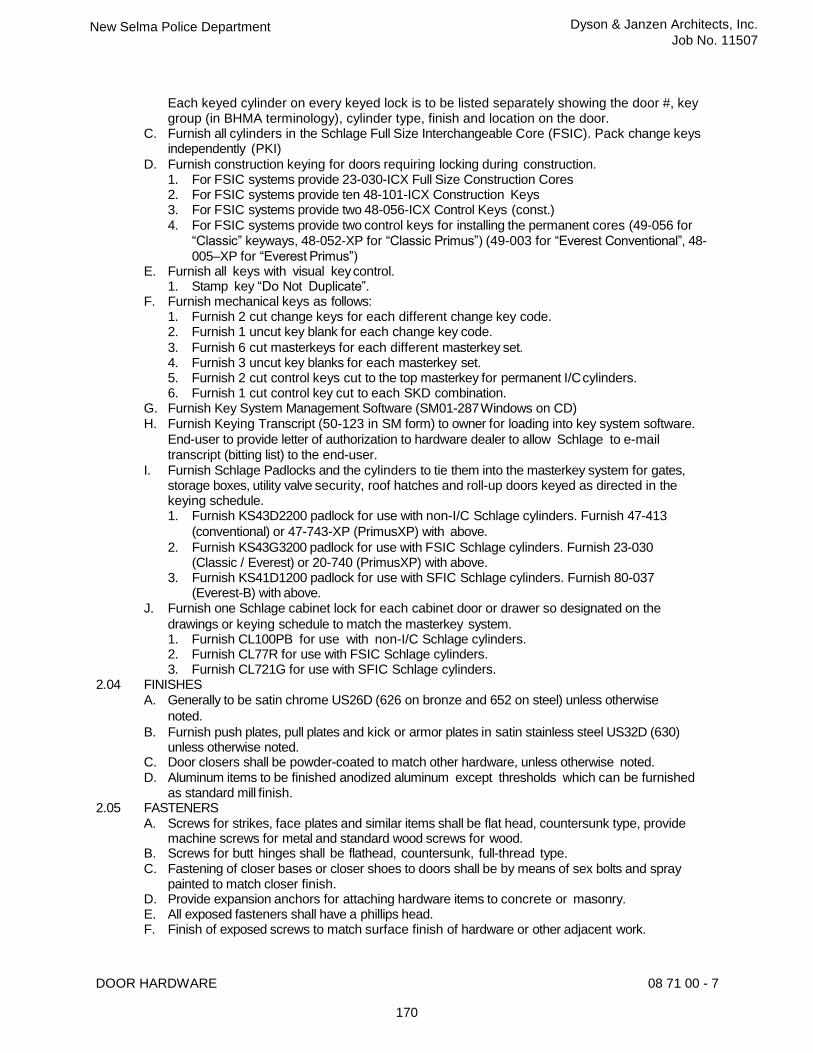
Each keyed cylinder on every keyed lock is to be listed separately showing the door #, key group (in BHMA terminology), cylinder type, finish and location on the door.
C. Furnish all cylinders in the Schlage Full Size Interchangeable Core (FSIC). Pack change keys independently (PKI)
D. Furnish construction keying for doors requiring locking during construction. 1. For FSIC systems provide 23-030-ICX Full Size Construction Cores 2. For FSIC systems provide ten 48-101-ICX Construction Keys 3. For FSIC systems provide two 48-056-ICX Control Keys (const.) 4. For FSIC systems provide two control keys for installing the permanent cores (49-056 for
“Classic” keyways, 48-052-XP for “Classic Primus”) (49-003 for “Everest Conventional”, 48-005–XP for “Everest Primus”)
E. Furnish all keys with visual key control. 1. Stamp key “Do Not Duplicate”.
F. Furnish mechanical keys as follows: 1. Furnish 2 cut change keys for each different change key code. 2. Furnish 1 uncut key blank for each change key code.
3. Furnish 6 cut masterkeys for each different masterkey set. 4. Furnish 3 uncut key blanks for each masterkey set. 5. Furnish 2 cut control keys cut to the top masterkey for permanent I/C cylinders. 6. Furnish 1 cut control key cut to each SKD combination.
G. Furnish Key System Management Software (SM01-287 Windows on CD) H. Furnish Keying Transcript (50-123 in SM form) to owner for loading into key system software.
End-user to provide letter of authorization to hardware dealer to allow Schlage to e-mail transcript (bitting list) to the end-user.
I. Furnish Schlage Padlocks and the cylinders to tie them into the masterkey system for gates, storage boxes, utility valve security, roof hatches and roll-up doors keyed as directed in the keying schedule. 1. Furnish KS43D2200 padlock for use with non-I/C Schlage cylinders. Furnish 47-413
(conventional) or 47-743-XP (PrimusXP) with above.
2. Furnish KS43G3200 padlock for use with FSIC Schlage cylinders. Furnish 23-030 (Classic / Everest) or 20-740 (PrimusXP) with above.
3. Furnish KS41D1200 padlock for use with SFIC Schlage cylinders. Furnish 80-037 (Everest-B) with above.
J. Furnish one Schlage cabinet lock for each cabinet door or drawer so designated on the
drawings or keying schedule to match the masterkey system. 1. Furnish CL100PB for use with non-I/C Schlage cylinders. 2. Furnish CL77R for use with FSIC Schlage cylinders. 3. Furnish CL721G for use with SFIC Schlage cylinders.
2.04 FINISHES A. Generally to be satin chrome US26D (626 on bronze and 652 on steel) unless otherwise
noted.
B. Furnish push plates, pull plates and kick or armor plates in satin stainless steel US32D (630) unless otherwise noted.
C. Door closers shall be powder-coated to match other hardware, unless otherwise noted. D. Aluminum items to be finished anodized aluminum except thresholds which can be furnished
as standard mill finish. 2.05 FASTENERS
A. Screws for strikes, face plates and similar items shall be flat head, countersunk type, provide machine screws for metal and standard wood screws for wood.
B. Screws for butt hinges shall be flathead, countersunk, full-thread type. C. Fastening of closer bases or closer shoes to doors shall be by means of sex bolts and spray
painted to match closer finish. D. Provide expansion anchors for attaching hardware items to concrete or masonry. E. All exposed fasteners shall have a phillips head. F. Finish of exposed screws to match surface finish of hardware or other adjacent work.

DOOR HARDWARE 08 71 00 - 8
171
New Selma Police Department Dyson & Janzen Architects, Inc.
Job No. 11507
G. All Exit Devices and Lock Protectors shall be fastened to the door by the means of sex bolts
or through bolts.
PART 3 - EXECUTION
3.01 INSPECTION A. Verify that doors and frames are square and plumb and ready to receive work and
dimensions are as instructed by the manufacturer. B. Beginning of installation means acceptance of existing conditions. C. Fire-Rated Door Assembly Inspection: Upon completion of the installation, all fire door
assemblies shall be inspected to confirm proper operation of the closing device and latching device and that only the manufacturer’s furnished fasteners are used for installation and that it meets all criteria of a fire door assembly per NFPA 80 (Standard for Fire Doors and Other Opening Protectives) 2013 Edition. A written record shall be maintained and transmitted to the Owner to be made available to the Authority Having Jurisdiction (AHJ). The inspection of the swinging fire doors shall be performed by a certified FDAI (Fire Door Assembly Inspector) with knowledge and understanding of the operating components of the type of door bei ng subjected to the inspection. The record shall list each fire door assembly throughout the project and include each door number, an itemized list of hardware set components at each door opening, and each door location in the facility.
3.02 INSTALLATION A. Install hardware in accordance with manufacturer's instructions and requirements of DHI. B. Use the templates provided by hardware item manufacturer.
C. Mounting heights for hardware shall be as recommended by the Door and Hardware Institute. Operating hardware will to be located between 34" and 44" AFF.
D. Set units level, plumb and true to line and location. Adjust and reinforce the attachment substrate as necessary for proper installation and operation.
E. Drill and countersink units that are not factory-prepared for anchorage fasteners. Space fasteners and anchors in accordance with industry standards.
F. Set thresholds for exterior doors in full bed of butyl-rubber sealant.
G. If hand of door is changed during construction, make necessary changes in hardware at no additional cost.
H. Hardware Installer shall coordinate with security contractor to route cable to connect electrified locks, panic hardware and fire exit hardware to power transfers or electric hinges at the time these items are installed so as to avoid disassembly and reinstallation of hardware.
I. Hardware Installer shall also be present with the security contractor when the power is turned on for the testing of the electronic hardware applications. Installer shall make adjustments to solenoids, latches, vertical rods and closers to insure proper and secure operation.
J. All wiring for electro-mechanical hardware mounted on the door shall be connected through the power transfer and terminated in the interface junction box specified for in the Electrical Section.
K. Conductors shall be minimum 18 gage stranded, multicolored. A minimum 12 in. loop of conductors shall be coiled in the interface junction box. Each conductor shall be permanently marked with its function.
L. If a power supply is specified in the hardware sets, all conductors shall be terminated in the power supply. Make all connections required for proper operation between the power supply and the electro-mechanical hardware. Provide the proper size conductors as specified in the manufacturer’s technical documentation.
3.03 ADJUST AND CLEAN A. Adjust and check each operating item of hardware and each door, to ensure proper operation
or function of every unit. Replace units which cannot be adjusted to operate freely and smoothly as intended for the application made.
B. Clean adjacent surface soiled by hardware installation.
C. Final Adjustment: Wherever hardware installation is made more than one month prior to acceptance or occupancy, return to that work area and make final check and adjustment of all hardware items in such space or area. Clean operating items as necessary to restore

DOOR HARDWARE 08 71 00 - 9
New Selma Police Department Dyson & Janzen Architects, Inc.
Job No. 11507
proper function and finish of hardware and doors. Adjust door control devices to compensate for final operation of heating and ventilating equipment.
D. Instruct Owner's Personnel in proper adjustment and maintenance of hardware finishes, during the final adjustment of hardware.
E. Continued Maintenance Service: Approximately six months after the completion of the project, the Contractor accompanied by the Architectural Hardware Consultant, shall return to the project and re-adjust every item of hardware to restore proper functions of doors and hardware. Consult with and instruct Owner's personnel in recommended additions to the maintenance procedures. Replace hardware items which have deteriorated or failed due to faulty design, materials or installation of hardware units. Prepare a written report of current and predictable problems (of substantial nature) in the performance of the hardware.
3.04 HARDWARE LOCATIONS A. Conform to CCR, Title 24, Part 2; and ADAAG; and the drawings for access-compliant
positioning requirements for the disabled. 3.05 FIELD QUALITY CONTROL
A. Contractor is responsible for providing the services of an Architectural Hardware Consultant (AHC) or a proprietary product technician to inspect installation and certify that hardware and its installation have been furnished and installed in accordance with manufacturers’ instructions and as specified herein.
3.06 SCHEDULE A. The items listed in the following schedule shall conform to the requirements of the foregoing
specifications.
B. While the hardware schedule is intended to cover all doors, and other movable parts of the building, and establish type and standard of quality, the contractor is responsible for examining the Plans and Specifications and furnishing proper hardware for all openings whether listed or not. If there are any omissions in hardware groups in regard to regular doors they shall be called to the attention of the Architect prior to bid opening for instruction; otherwise, list will be considered Complete. No extras will be allowed for omissions.
C. The Door Schedule on the Drawings indicates which hardware set is used with each door. Manufacturers Abbreviations (Mfr.) GLY IVE
= =
Glynn-Johnson Corporation Ives
Overhead Door Stops Hinges, Pivots, Bolts, Coordinators, Dust Proof Strikes, Push Pull & Kick Plates, Door Stops & Silencers
LCN = LCN Door Closers SCE = Schlage Electronics Electronic Door Components SCH = Schlage Lock Company Locks, Latches & Cylinders VON = Von Duprin Exit Devices ZER = Zero International Thresholds, Gasketing & Weather-stripping

DOOR HARDWARE 08 71 00 - 10
New Selma Police Department Dyson & Janzen Architects, Inc.
Job No. 11507
HARDWARE GROUPS
HARDWARE GROUP NO. 01 - EXTERIOR PAIR / PANIC HARDWARE
FOR USE ON MARK/DOOR #(S): 01
EACH TO HAVE: QTY DESCRIPTION CATALOG NUMBER FINISH MFR
2 EA CONT. HINGE 112XY 628 IVE 1 EA PANIC HARDWARE PA-9949-DT 626 VON 1 EA PANIC HARDWARE PA-9949-NL 626 VON 1 EA RIM CYLINDER 20-057-ICX 626 SCH 1 EA FSIC CORE 23-030 626 SCH 2 EA SURFACE CLOSER 4040XP EDA 689 LCN 2 EA KICK PLATE 8400 10" X 2" LDW 630 IVE 2 EA FLOOR STOP FS444 626 IVE 1 SET WEATHER SEAL SUPPLY WITH DOOR AND FRAME
ASSEMBLY
2 EA DOOR SWEEP 39A A ZER 1 EA THRESHOLD PER DETAIL
HARDWARE GROUP NO. 02 - ADD ALT. NO.1 / EXTERIOR / PANIC HARDWARE
FOR USE ON MARK/DOOR #(S): 63
EACH TO HAVE: QTY DESCRIPTION CATALOG NUMBER FINISH MFR
1 EA CONT. HINGE 112XY 628 IVE 1 EA PANIC HARDWARE PA-AX-99-NL 626 VON 1 EA RIM CYLINDER 20-057-ICX 626 SCH 1 EA FSIC CORE 23-030 626 SCH 1 EA SURFACE CLOSER 4040XP EDA 689 LCN 1 EA KICK PLATE 8400 10" X 2" LDW 630 IVE 1 EA FLOOR STOP FS444 626 IVE 1 EA GASKETING 188S-BK S-BK ZER 1 EA DOOR SWEEP 39A A ZER 1 EA THRESHOLD PER DETAIL
MRussell
Cloud
MRussell
Text Box
2
MRussell
PolyLine
MRussell
Text Box
2
MRussell
PolyLine
MRussell
Cloud
MRussell
Text Box
2
MRussell
PolyLine
MRussell
Cloud

DOOR HARDWARE 08 71 00 - 11
New Selma Police Department Dyson & Janzen Architects, Inc.
Job No. 11507
HARDWARE GROUP NO. 03 - EXTERIOR PAIR / ELEC. / ACCESS CONTROL
FOR USE ON MARK/DOOR #(S): 02
EACH TO HAVE: QTY DESCRIPTION CATALOG NUMBER FINISH MFR
5 EA HW HINGE 5BB1HW 4.5 X 4.5 NRP 630 IVE 1 EA ELECTRIC HW HINGE 5BB1HW 4.5 X 4.5 CON TW8 630 IVE 2 EA MANUAL FLUSH BOLT FB457 626 IVE 1 EA DUST PROOF STRIKE DP1 626 IVE 1 EA EU MORTISE LOCK L9092TEU 06A RX 626 SCH 1 EA FSIC CORE 23-030 626 SCH 1 EA OH STOP 100S 630 GLY 1 EA FLOOR STOP FS444 626 IVE 1 EA GASKETING 188S-BK S-BK ZER 1 EA ASTRAGAL 43SP
OR BY DOOR MFG ZER
2 EA DOOR SWEEP 39A A ZER 1 EA THRESHOLD PER DETAIL 1 EA POWER SUPPLY PS902 LGR VON
CARD READER AND WIRING FURNISHED BY ACCESS CONTROL SECTION
HARDWARE GROUP NO. 04 - EXTERIOR / ACCESS CONTROL
FOR USE ON MARK/DOOR #(S): 03
EACH TO HAVE: QTY DESCRIPTION CATALOG NUMBER FINISH MFR
1 EA CONT. HINGE 112XY TWP CON 628 IVE 1 EA EU MORTISE LOCK L9092TEU 06A RX 626 SCH 1 EA FSIC CORE 23-030 626 SCH 1 EA LOCK GUARD LG10 630 IVE 1 EA SURFACE CLOSER 4040XP EDA 689 LCN 1 EA FLOOR STOP FS444 626 IVE 1 EA GASKETING 188S-BK S-BK ZER 1 EA DOOR SWEEP 39A A ZER 1 EA THRESHOLD PER DETAIL 1 EA POWER SUPPLY PS902 LGR VON
CARD READER AND WIRING FURNISHED BY ACCESS CONTROL SECTION
MRussell
Text Box
2
MRussell
PolyLine
MRussell
Cloud
MRussell
Text Box
2
MRussell
PolyLine
MRussell
Cloud

DOOR HARDWARE 08 71 00 - 12
New Selma Police Department Dyson & Janzen Architects, Inc.
Job No. 11507
HARDWARE GROUP NO. 05 - EXTERIOR / PANIC HARDWARE / ACCESS CONTROL
FOR USE ON MARK/DOOR #(S): 04 08
EACH TO HAVE: QTY DESCRIPTION CATALOG NUMBER FINISH MFR
1 EA CONT. HINGE 112XY TWP CON 628 IVE 1 EA ELEC PANIC
HARDWARE RX-LD-PA-AX-99-L-E996-06-FSE-CON 626 VON
1 EA RIM CYLINDER 20-057-ICX 626 SCH 1 EA FSIC CORE 23-030 626 SCH 1 EA SURFACE CLOSER 4040XP EDA 689 LCN 1 EA KICK PLATE 8400 10" X 2" LDW 630 IVE 1 EA FLOOR STOP FS444 626 IVE 1 EA GASKETING 188S-BK S-BK ZER 1 EA DOOR SWEEP 39A A ZER 1 EA THRESHOLD PER DETAIL 1 EA POWER SUPPLY PS902 LGR VON
CARD READER AND WIRING FURNISHED BY ACCESS CONTROL SECTION
HARDWARE GROUP NO. 05A - EXTERIOR / ACCESS CONTROL / CARD READER BOTH SIDES OF OPENING
FOR USE ON MARK/DOOR #(S): 06
EACH TO HAVE: QTY DESCRIPTION CATALOG NUMBER FINISH MFR
1 EA CONT. HINGE 112XY TWP CON 628 IVE 1 EA EU MORTISE LOCK L9095TEU 06A RX 626 SCH 2 EA FSIC CORE 23-030 626 SCH 1 EA SURFACE CLOSER 4040XP EDA 689 LCN 1 EA KICK PLATE 8400 10" X 2" LDW 630 IVE 1 EA FLOOR STOP FS444 626 IVE 1 EA GASKETING 188S-BK S-BK ZER 1 EA DOOR SWEEP 39A A ZER 1 EA THRESHOLD PER DETAIL 1 EA POWER SUPPLY PS902 LGR VON
CARD READER AND WIRING FURNISHED BY ACCESS CONTROL SECTION
MRussell
Text Box
2
MRussell
PolyLine
MRussell
Cloud
MRussell
Text Box
2
MRussell
PolyLine
MRussell
Cloud

DOOR HARDWARE 08 71 00 - 13
New Selma Police Department Dyson & Janzen Architects, Inc.
Job No. 11507
HARDWARE GROUP NO. 06 - EXTERIOR / JAIL RELEASE / MAG-LOCK, E/O PANIC HARDWARE / CARD READER AT INTERIOR TO EXIT DOOR
FOR USE ON MARK/DOOR #(S): 05
EACH TO HAVE: QTY DESCRIPTION CATALOG NUMBER FINISH MFR
1 EA CONT. HINGE 112XY 628 IVE 1 EA PANIC HARDWARE LD-PA-AX-99-EO-SNB 626 VON 1 EA MAGNETIC LOCK M490P 628 SCE 1 EA SURFACE CLOSER 4040XP EDA 689 LCN 1 EA KICK PLATE 8400 10" X 2" LDW 630 IVE 1 EA FLOOR STOP FS444 626 IVE 1 EA GASKETING 188S-BK S-BK ZER 1 EA DOOR SWEEP 39A A ZER 1 EA THRESHOLD PER DETAIL 1 EA POWER SUPPLY PS902 LGR VON
NOTE: VERIFY FUNCTION WITH OWNER BEFORE ORDERING. CARD READER TO RELEASE MAG LOCK. CARD READER AND WIRING FURNISHED BY ACCESS CONTROL SECTION
HARDWARE GROUP NO. 07 - EXTERIOR / WATER HEATER
FOR USE ON MARK/DOOR #(S): 07
EACH TO HAVE: QTY DESCRIPTION CATALOG NUMBER FINISH MFR
3 EA HW HINGE 5BB1HW 4.5 X 4.5 NRP 630 IVE 1 EA STOREROOM LOCK L9080T 06A 626 SCH 1 EA FSIC CORE 23-030 626 SCH 1 EA SURFACE CLOSER 1461 RW/PA FC 689 LCN 1 EA FLOOR STOP FS444 626 IVE 1 EA GASKETING 188S-BK S-BK ZER 1 EA DOOR SWEEP 39A A ZER 1 EA THRESHOLD PER DETAIL
HARDWARE GROUP NO. 08 - INTERIOR / RATED / RESTROOM WITH "OCCUPIED" INDICATOR LOCK
FOR USE ON MARK/DOOR #(S): 09
EACH TO HAVE: QTY DESCRIPTION CATALOG NUMBER FINISH MFR
4 EA HW HINGE 5BB1HW 4.5 X 4.5 652 IVE 1 EA CORRIDOR LOCK L9456T 06A L583-363 L283-722 626 SCH 1 EA FSIC CORE 23-030 626 SCH 1 EA SURFACE CLOSER 4040XP RW/PA 689 LCN 1 EA KICK PLATE 8400 10" X 2" LDW 630 IVE 1 EA FLOOR STOP FS436 626 IVE 1 EA GASKETING 188S-BK S-BK ZER
MRussell
Text Box
2
MRussell
PolyLine
MRussell
Cloud
MRussell
Text Box
2
MRussell
PolyLine
MRussell
Cloud
MRussell
Text Box
2
MRussell
PolyLine
MRussell
Cloud

DOOR HARDWARE 08 71 00 - 14
New Selma Police Department Dyson & Janzen Architects, Inc.
Job No. 11507
HARDWARE GROUP NO. 09 - ADD ALT. NO.1 / INTERIOR / RATED / PANIC HARDWARE
FOR USE ON MARK/DOOR #(S): 64
EACH TO HAVE: QTY DESCRIPTION CATALOG NUMBER FINISH MFR
4 EA HW HINGE 5BB1HW 4.5 X 4.5 NRP 652 IVE 1 EA FIRE EXIT HARDWARE PA-AX-99-L-F-06 626 VON 1 EA RIM CYLINDER 20-057-ICX 626 SCH 1 EA FSIC CORE 23-030 626 SCH 1 EA SURFACE CLOSER 4040XP EDA 689 LCN 1 EA KICK PLATE 8400 10" X 2" LDW 630 IVE 1 EA FLOOR STOP FS444 626 IVE 1 EA GASKETING 188S-BK S-BK ZER EA THRESHOLD PER DETAIL
HARDWARE GROUP NO. 10 - INTERIOR / ACCESS CONTROL
FOR USE ON MARK/DOOR #(S): 10
EACH TO HAVE: QTY DESCRIPTION CATALOG NUMBER FINISH MFR
3 EA HW HINGE 5BB1HW 4.5 X 4.5 NRP 652 IVE 1 EA ELECTRIC HW HINGE 5BB1HW 4.5 X 4.5 CON TW8 652 IVE 1 EA EU MORTISE LOCK L9092TEU 06A RX 626 SCH 1 EA FSIC CORE 23-030 626 SCH 1 EA SURFACE CLOSER 4040XP RW/PA 689 LCN 1 EA FLOOR STOP FS436 626 IVE 1 EA GASKETING 188S-BK S-BK ZER 1 EA POWER SUPPLY PS902 LGR VON
CARD READER AND WIRING FURNISHED BY ACCESS CONTROL SECTION
MRussell
Text Box
2
MRussell
PolyLine
MRussell
Cloud
MRussell
Text Box
2
MRussell
PolyLine
MRussell
Cloud

DOOR HARDWARE 08 71 00 - 15
New Selma Police Department Dyson & Janzen Architects, Inc.
Job No. 11507
HARDWARE GROUP NO. 11 - INTERIOR / RATED / LIVE SCAN
FOR USE ON MARK/DOOR #(S): 12
EACH TO HAVE: QTY DESCRIPTION CATALOG NUMBER FINISH MFR
3 EA HW HINGE 5BB1HW 4.5 X 4.5 652 IVE 1 EA PASSAGE SET L9010 06A 626 SCH 1 EA OH STOP 100S 630 GLY 1 EA SURFACE CLOSER 4040XP RW/PA 689 LCN 1 EA KICK PLATE 8400 10" X 2" LDW 630 IVE 1 EA GASKETING 188S-BK S-BK ZER
HARDWARE GROUP NO. 12 - INTERIOR / RATED / PANIC HARDWARE / ACCESS CONTROL
FOR USE ON MARK/DOOR #(S): 11
EACH TO HAVE: QTY DESCRIPTION CATALOG NUMBER FINISH MFR
4 EA HW HINGE 5BB1HW 4.5 X 4.5 NRP 652 IVE 1 EA POWER TRANSFER EPT10 CON 689 VON 1 EA ELEC FIRE EXIT
HARDWARE RX-PA-AX-99-L-F-E996-06-FSE-CON 626 VON
1 EA RIM CYLINDER 20-057-ICX 626 SCH 1 EA FSIC CORE 23-030 626 SCH 1 EA SURFACE CLOSER 4040XP EDA 689 LCN 1 EA KICK PLATE 8400 10" X 2" LDW 630 IVE 1 EA FLOOR STOP FS444 626 IVE 1 EA GASKETING 188S-BK S-BK ZER 1 EA THRESHOLD PER DETAIL 1 EA POWER SUPPLY PS902 LGR VON
CARD READER AND WIRING FURNISHED BY ACCESS CONTROL SECTION
MRussell
Text Box
2
MRussell
PolyLine
MRussell
Cloud
MRussell
Text Box
2
MRussell
PolyLine
MRussell
Cloud

DOOR HARDWARE 08 71 00 - 16
New Selma Police Department Dyson & Janzen Architects, Inc.
Job No. 11507
HARDWARE GROUP NO. 13 - INTERIOR / RATED / CARD READER
FOR USE ON MARK/DOOR #(S): 13 14 29 30 33 34 36 37 38 44 45
EACH TO HAVE: QTY DESCRIPTION CATALOG NUMBER FINISH MFR
2 EA HW HINGE 5BB1HW 4.5 X 4.5 652 IVE 1 EA ELECTRIC HW HINGE 5BB1HW 4.5 X 4.5 CON TW8 652 IVE 1 EA EU MORTISE LOCK L9092TEU 06A RX 626 SCH 1 EA FSIC CORE 23-030 626 SCH 1 EA SURFACE CLOSER 1461 FC 689 LCN 1 EA KICK PLATE 8400 10" X 2" LDW 630 IVE 1 EA FLOOR STOP FS436 626 IVE 1 EA GASKETING 188S-BK S-BK ZER 1 EA POWER SUPPLY PS902 LGR VON
CARD READER AND WIRING FURNISHED BY ACCESS CONTROL SECTION
HARDWARE GROUP NO. 14 - INTERIOR / CARD READER
FOR USE ON MARK/DOOR #(S): 40
EACH TO HAVE: QTY DESCRIPTION CATALOG NUMBER FINISH MFR
2 EA HW HINGE 5BB1HW 4.5 X 4.5 NRP 652 IVE 1 EA ELECTRIC HW HINGE 5BB1HW 4.5 X 4.5 CON TW8 652 IVE 1 EA EU MORTISE LOCK L9092TEU 06A RX 626 SCH 1 EA FSIC CORE 23-030 626 SCH 1 EA SURFACE CLOSER 1461 FC 689 LCN 1 EA KICK PLATE 8400 10" X 2" LDW 630 IVE 1 EA FLOOR STOP FS436 626 IVE 1 EA GASKETING 188S-BK S-BK ZER 1 EA POWER SUPPLY PS902 LGR VON
CARD READER AND WIRING FURNISHED BY ACCESS CONTROL SECTION
HARDWARE GROUP NO. 15A - INTERIOR / RATED / INTERVIEW, CONF, EVIDENCE PROCESS, PATROL SQUAD ROOM, COPY, BREAK ROOM
FOR USE ON MARK/DOOR #(S): 16 17 25 32 41 42
EACH TO HAVE: QTY DESCRIPTION CATALOG NUMBER FINISH MFR
3 EA HW HINGE 5BB1HW 4.5 X 4.5 652 IVE 1 EA PASSAGE SET L9010 06A 626 SCH 1 EA SURFACE CLOSER 4040XP 689 LCN 1 EA KICK PLATE 8400 10" X 2" LDW 630 IVE 1 EA FLOOR STOP FS436 626 IVE 1 EA GASKETING 188S-BK S-BK ZER
MRussell
Text Box
2
MRussell
PolyLine
MRussell
Cloud
MRussell
Text Box
2
MRussell
PolyLine
MRussell
Cloud
MRussell
Text Box
2
MRussell
PolyLine
MRussell
Cloud

DOOR HARDWARE 08 71 00 - 17
New Selma Police Department Dyson & Janzen Architects, Inc.
Job No. 11507
HARDWARE GROUP NO. 16A - INTERIOR / CARD READER / POLICE CHIEF, SERGEANT
FOR USE ON MARK/DOOR #(S): 15 18 39
EACH TO HAVE: QTY DESCRIPTION CATALOG NUMBER FINISH MFR
2 EA HW HINGE 5BB1HW 4.5 X 4.5 NRP 652 IVE 1 EA ELECTRIC HW HINGE 5BB1HW 4.5 X 4.5 CON TW8 652 IVE 1 EA EU MORTISE LOCK L9092TEU 06A RX 626 SCH 1 EA FSIC CORE 23-030 626 SCH 1 EA FLOOR STOP FS436 626 IVE 3 EA SILENCER SR64 GRY IVE 1 EA POWER SUPPLY PS902 LGR VON
CARD READER AND WIRING FURNISHED BY ACCESS CONTROL SECTION
HARDWARE GROUP NO. 16B - INTERIOR / CARD READER / COMPUTER ROOM, COMM SUPV
FOR USE ON MARK/DOOR #(S): 43 47
EACH TO HAVE: QTY DESCRIPTION CATALOG NUMBER FINISH MFR
2 EA HW HINGE 5BB1HW 4.5 X 4.5 NRP 652 IVE 1 EA ELECTRIC HW HINGE 5BB1HW 4.5 X 4.5 CON TW8 652 IVE 1 EA EU MORTISE LOCK L9092TEU 06A RX 626 SCH 1 EA FSIC CORE 23-030 626 SCH 1 EA SURFACE CLOSER 4040XP 689 LCN 1 EA KICK PLATE 8400 10" X 2" LDW 630 IVE 1 EA FLOOR STOP FS436 626 IVE 3 EA SILENCER SR64 GRY IVE 1 EA POWER SUPPLY PS902 LGR VON
CARD READER AND WIRING FURNISHED BY ACCESS CONTROL SECTION
HARDWARE GROUP NO. 17 - INTERIOR / RESTROOM WITH "OCCUPIED" INDICATOR LOCK
FOR USE ON MARK/DOOR #(S): 46
EACH TO HAVE: QTY DESCRIPTION CATALOG NUMBER FINISH MFR
3 EA HW HINGE 5BB1HW 4.5 X 4.5 652 IVE 1 EA PRIVACY LOCK L9040 06A L583-363 L283-722 626 SCH 1 EA SURFACE CLOSER 1461 RW/PA FC 689 LCN 1 EA KICK PLATE 8400 10" X 2" LDW 630 IVE 1 EA FLOOR STOP FS436 626 IVE 1 EA GASKETING 188S-BK S-BK ZER
MRussell
Text Box
2
MRussell
PolyLine
MRussell
Cloud
MRussell
Text Box
2
MRussell
PolyLine
MRussell
Cloud
MRussell
Text Box
2
MRussell
PolyLine
MRussell
Cloud

DOOR HARDWARE 08 71 00 - 18
New Selma Police Department Dyson & Janzen Architects, Inc.
Job No. 11507
HARDWARE GROUP NO. 18 - INTERIOR / RATED / JANITOR
FOR USE ON MARK/DOOR #(S): 20
EACH TO HAVE: QTY DESCRIPTION CATALOG NUMBER FINISH MFR
3 EA HW HINGE 5BB1HW 4.5 X 4.5 NRP 652 IVE 1 EA STOREROOM LOCK L9080T 06A 626 SCH 1 EA FSIC CORE 23-030 626 SCH 1 EA SURFACE CLOSER 4040XP RW/PA 689 LCN 1 EA KICK PLATE 8400 10" X 2" LDW 630 IVE 1 EA FLOOR STOP FS436 626 IVE 1 EA GASKETING 188S-BK S-BK ZER 1 EA THRESHOLD PER DETAIL
HARDWARE GROUP NO. 18A - INTERIOR / JANITOR
FOR USE ON MARK/DOOR #(S): 50 59
EACH TO HAVE: QTY DESCRIPTION CATALOG NUMBER FINISH MFR
3 EA HW HINGE 5BB1HW 4.5 X 4.5 NRP 652 IVE 1 EA STOREROOM LOCK L9080T 06A 626 SCH 1 EA FSIC CORE 23-030 626 SCH 1 EA OH STOP 100S 630 GLY 1 EA SURFACE CLOSER 4040XP RW/PA 689 LCN 1 EA KICK PLATE 8400 10" X 2" LDW 630 IVE 3 EA SILENCER SR64 GRY IVE
HARDWARE GROUP NO. 19 - INTERIOR / RATED / MULTI-STALL RESTROOM
FOR USE ON MARK/DOOR #(S): 21 23
EACH TO HAVE: QTY DESCRIPTION CATALOG NUMBER FINISH MFR
3 EA HW HINGE 5BB1HW 4.5 X 4.5 652 IVE 1 EA PASSAGE SET L9010 06A 626 SCH 1 EA FSIC CORE 23-030 626 SCH 1 EA SURFACE CLOSER 4040XP 689 LCN 1 EA KICK PLATE 8400 10" X 2" LDW 630 IVE 1 EA MOP PLATE 8400 4" X 1" LDW B-CS 630 IVE 1 EA WALL STOP WS401/402CCV 626 IVE 1 EA GASKETING 188S-BK S-BK ZER
MRussell
Text Box
2
MRussell
PolyLine
MRussell
Cloud

DOOR HARDWARE 08 71 00 - 19
New Selma Police Department Dyson & Janzen Architects, Inc.
Job No. 11507
HARDWARE GROUP NO. 20 - INTERIOR / LOCKERS / CARD READER
FOR USE ON MARK/DOOR #(S): 22 24
EACH TO HAVE: QTY DESCRIPTION CATALOG NUMBER FINISH MFR
2 EA HW HINGE 5BB1HW 4.5 X 4.5 652 IVE 1 EA ELECTRIC HW HINGE 5BB1HW 4.5 X 4.5 CON TW8 652 IVE 1 EA EU MORTISE LOCK L9092TEU 06A RX 626 SCH 1 EA FSIC CORE 23-030 626 SCH 1 EA OH STOP 100S 630 GLY 1 EA SURFACE CLOSER 4040XP RW/PA 689 LCN 1 EA KICK PLATE 8400 10" X 2" LDW 630 IVE 1 EA MOP PLATE 8400 4" X 1" LDW B-CS 630 IVE 3 EA SILENCER SR64 GRY IVE 1 EA POWER SUPPLY PS902 LGR VON
CARD READER AND WIRING FURNISHED BY ACCESS CONTROL SECTION
HARDWARE GROUP NO. 22 - INTERIOR PAIR / RATED / EVIDENCE ROOM / ACCESS CONTROL
FOR USE ON MARK/DOOR #(S): 26
EACH TO HAVE: QTY DESCRIPTION CATALOG NUMBER FINISH MFR
5 EA HW HINGE 5BB1HW 4.5 X 4.5 652 IVE 1 EA ELECTRIC HW HINGE 5BB1HW 4.5 X 4.5 CON TW8 652 IVE 1 SET AUTO FLUSH BOLT FB41P 630 IVE 1 EA DUST PROOF STRIKE DP1 626 IVE 1 EA EU MORTISE LOCK L9092TEU 06A RX 626 SCH 1 EA FSIC CORE 23-030 626 SCH 1 EA COORDINATOR COR X FL 628 IVE 2 EA SURFACE CLOSER 1461 FC 689 LCN 2 EA KICK PLATE 8400 10" X 2" LDW 630 IVE 2 EA FLOOR STOP FS436 626 IVE 1 EA GASKETING 188S-BK S-BK ZER 1 EA THRESHOLD PER DETAIL 1 EA POWER SUPPLY PS902 LGR VON
CARD READER AND WIRING FURNISHED BY ACCESS CONTROL SECTION
MRussell
Text Box
2
MRussell
PolyLine
MRussell
Cloud
MRussell
Text Box
2
MRussell
PolyLine
MRussell
Cloud

DOOR HARDWARE 08 71 00 - 20
New Selma Police Department Dyson & Janzen Architects, Inc.
Job No. 11507
HARDWARE GROUP NO. 23 - INTERIOR / EVIDENCE ROOM / ACCESS CONTROL
FOR USE ON MARK/DOOR #(S): 27
EACH TO HAVE: QTY DESCRIPTION CATALOG NUMBER FINISH MFR
2 EA HW HINGE 5BB1HW 4.5 X 4.5 NRP 652 IVE 1 EA ELECTRIC HW HINGE 5BB1HW 4.5 X 4.5 CON TW8 652 IVE 1 EA EU MORTISE LOCK L9092TEU 06A RX 626 SCH 1 EA FSIC CORE 23-030 626 SCH 1 EA KICK PLATE 8400 10" X 2" LDW 630 IVE 1 EA FLOOR STOP FS436 626 IVE 3 EA SILENCER SR64 GRY IVE 1 EA POWER SUPPLY PS902 LGR VON
CARD READER AND WIRING FURNISHED BY ACCESS CONTROL SECTION
HARDWARE GROUP NO. 24 - INTERIOR / STORAGE
FOR USE ON MARK/DOOR #(S): 28
EACH TO HAVE: QTY DESCRIPTION CATALOG NUMBER FINISH MFR
3 EA HW HINGE 5BB1HW 4.5 X 4.5 652 IVE 1 EA STOREROOM LOCK L9080T 06A 626 SCH 1 EA FSIC CORE 23-030 626 SCH 1 EA SURFACE CLOSER 4040XP 689 LCN 1 EA KICK PLATE 8400 10" X 2" LDW 630 IVE 1 EA WALL STOP WS401/402CCV 626 IVE 3 EA SILENCER SR64 GRY IVE
HARDWARE GROUP NO. 25 - INTERIOR
FOR USE ON MARK/DOOR #(S): 54 55
EACH TO HAVE: QTY DESCRIPTION CATALOG NUMBER FINISH MFR
3 EA HW HINGE 5BB1HW 4.5 X 4.5 NRP 652 IVE 1 EA PASSAGE SET L9010 06A 626 SCH 1 EA SURFACE CLOSER 4040XP EDA 689 LCN 1 EA KICK PLATE 8400 10" X 2" LDW 630 IVE 1 EA FLOOR STOP FS436 626 IVE 3 EA SILENCER SR64 GRY IVE
MRussell
Text Box
2
MRussell
PolyLine
MRussell
Cloud
MRussell
Text Box
2
MRussell
PolyLine
MRussell
Cloud
DOOR HARDWARE 08 71 00 - 21
New Selma Police Department Dyson & Janzen Architects, Inc.
Job No. 11507
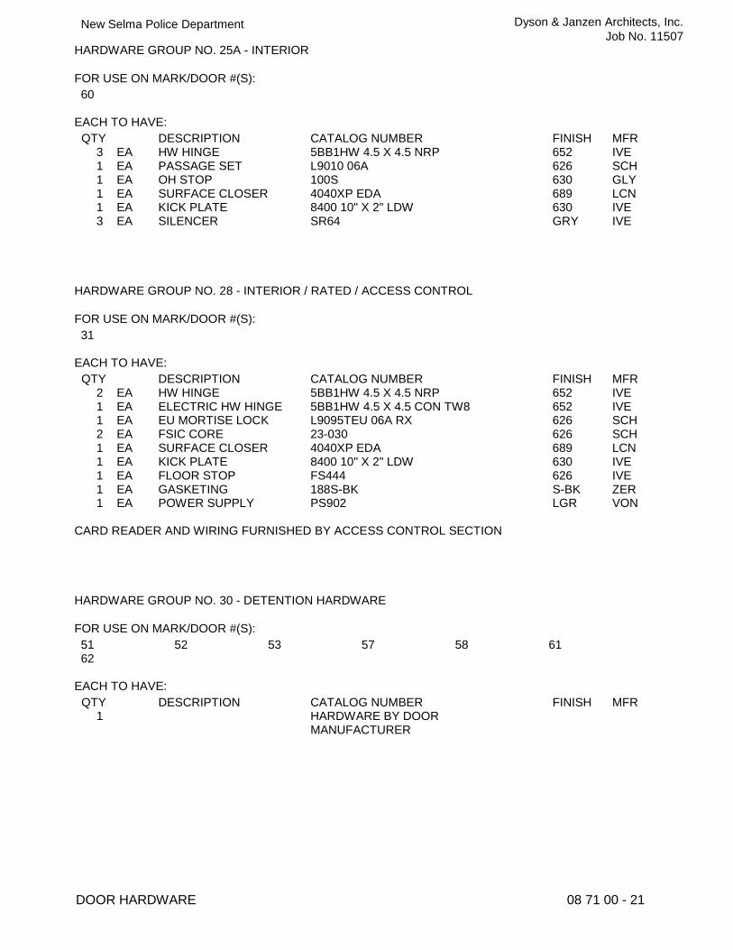
HARDWARE GROUP NO. 25A - INTERIOR
FOR USE ON MARK/DOOR #(S): 60
EACH TO HAVE: QTY DESCRIPTION CATALOG NUMBER FINISH MFR
3 EA HW HINGE 5BB1HW 4.5 X 4.5 NRP 652 IVE 1 EA PASSAGE SET L9010 06A 626 SCH 1 EA OH STOP 100S 630 GLY 1 EA SURFACE CLOSER 4040XP EDA 689 LCN 1 EA KICK PLATE 8400 10" X 2" LDW 630 IVE 3 EA SILENCER SR64 GRY IVE
HARDWARE GROUP NO. 28 - INTERIOR / RATED / ACCESS CONTROL
FOR USE ON MARK/DOOR #(S): 31
EACH TO HAVE: QTY DESCRIPTION CATALOG NUMBER FINISH MFR
2 EA HW HINGE 5BB1HW 4.5 X 4.5 NRP 652 IVE 1 EA ELECTRIC HW HINGE 5BB1HW 4.5 X 4.5 CON TW8 652 IVE 1 EA EU MORTISE LOCK L9095TEU 06A RX 626 SCH 2 EA FSIC CORE 23-030 626 SCH 1 EA SURFACE CLOSER 4040XP EDA 689 LCN 1 EA KICK PLATE 8400 10" X 2" LDW 630 IVE 1 EA FLOOR STOP FS444 626 IVE 1 EA GASKETING 188S-BK S-BK ZER 1 EA POWER SUPPLY PS902 LGR VON
CARD READER AND WIRING FURNISHED BY ACCESS CONTROL SECTION
HARDWARE GROUP NO. 30 - DETENTION HARDWARE
FOR USE ON MARK/DOOR #(S): 51 52 53 57 58 61 62
EACH TO HAVE: QTY DESCRIPTION CATALOG NUMBER FINISH MFR
1 HARDWARE BY DOOR MANUFACTURER
MRussell
Text Box
2
MRussell
PolyLine
MRussell
Cloud
MRussell
Text Box
2
MRussell
PolyLine
MRussell
Cloud
MRussell
Text Box
Refer To Section 11 98 12 - DETENTION DOORS AND FRAMES

DOOR HARDWARE 08 71 00 - 22
New Selma Police Department Dyson & Janzen Architects, Inc.
Job No. 11507
HARDWARE GROUP NO. 31 - EXTERIOR / UNEQUAL PAIR OF GATES / THE SMALLER LEAF IS THE ACTIVE GATE
FOR USE ON MARK/DOOR #(S): MG-1 MG-2
EACH TO HAVE: QTY DESCRIPTION CATALOG NUMBER FINISH MFR
1 EA VANDL STOREROOM LOCK
ND96TD RHO 626 SCH
1 EA FSIC CORE 23-030 626 SCH 1 BALANCE OF HARDWARE BY GATE
MANUFACTURER
HARDWARE GROUP NO. 32 - EXTERIOR GATE / EXIT ONLY PANIC HARDWARE
FOR USE ON MARK/DOOR #(S): MG-3
EACH TO HAVE: QTY DESCRIPTION CATALOG NUMBER FINISH MFR
1 EA PANIC HARDWARE PA-AX-99-EO-WH 626 VON 1 BALANCE OF HARDWARE BY GATE
MANUFACTURER
End of Section
MRussell
Text Box
2
MRussell
PolyLine
MRussell
Text Box
2
MRussell
PolyLine
MRussell
Cloud
MRussell
Cloud

DOOR SCHEDULENO. QTY. SIZE DOOR
TYPEDOORMAT'L.
FRAMEMAT'L. ELEV.
RATEDASSEMBLY HEAD
DETAILSJAMB THRSHLD
HDWR.GROUP
SEE SYMBOL ON FLOOR PLANS
EX
TER
IOR
INTE
RIO
R
TYPE FL TYPE FGTYPE VPTYPE FL-L
REMARKSSIGNAGE SCHEDULE
TYPE ROOM ID. SIGN TEXT
TYPE VP-D
DOOR / WINDOW
WINDOW
DOOR DESIGNATIONS
DOOR TYPES
FRAME DESIGNATIONS
HM FRAME TYPESDOOR SCHEDULE NOTES
VEHICLE GATE SCHEDULENO. QTY. SIZE GATE
TYPEGATEMAT'L.
FRAMEMAT'L. ELEV.
DETAIL HDWR.GROUP
SEE SYMBOL ON SITE PLANS
REMARKS
VEHICLE GATE SCHEDULE NOTES
TYPE MG-2
A A
TYPE MG: DETAIL A-ATYPE HM
TYPE VP-D-PT
GA
TES
DOOR SCHEDULENO. QTY. SIZE DOOR
TYPEDOORMAT'L.
FRAMEMAT'L. ELEV.
RATEDASSEMBLY HEAD
DETAILSJAMB THRSHLD
HDWR.GROUP
CONTINUED
REMARKSSIGNAGE SCHEDULETYPE
TYPE MG-1
1295 N. Wishon Ave.Fresno, CA 93728
Phone 559.497.6370Fax 559.486.4909
Web: dsjarchitects.com
Arthur DysonArchitect
A.I.A.C-16824
Douglas K. JanzenR.A.Architect C-14260
Dyson Siegrist JanzenArchitects, Inc.
AutoCAD SHX Text
LOCK BLOCKS PER GATE MGFR.
AutoCAD SHX Text
3/16" THK. G.I. PLATE. OR MGFR'S LOCK BLOCK AS REQUIRED TO MOUNT EXIT DEVICE
AutoCAD SHX Text
XX
AutoCAD SHX Text
01
AutoCAD SHX Text
W
AutoCAD SHX Text
1/A801
AutoCAD SHX Text
1/A-801
AutoCAD SHX Text
AL
AutoCAD SHX Text
1-PAIR
AutoCAD SHX Text
3' x 8' x 1-3/4"
AutoCAD SHX Text
FG
AutoCAD SHX Text
AL
AutoCAD SHX Text
01
AutoCAD SHX Text
--
AutoCAD SHX Text
ISA
AutoCAD SHX Text
NOTED ON SCHED.
AutoCAD SHX Text
EXIT
AutoCAD SHX Text
DEVICE
AutoCAD SHX Text
PULL
AutoCAD SHX Text
T
AutoCAD SHX Text
NOTE: FIELD VERIFY ALL DIMENSIONS
AutoCAD SHX Text
T
AutoCAD SHX Text
LOUVER. SEE
AutoCAD SHX Text
MECH. DRAWINGS
AutoCAD SHX Text
KICKPLATE AS
AutoCAD SHX Text
4/A802
AutoCAD SHX Text
--
AutoCAD SHX Text
SEE SHEET A-004 FOR A-004 FOR FOR SIGNAGE TYPES
AutoCAD SHX Text
02
AutoCAD SHX Text
03
AutoCAD SHX Text
B
AutoCAD SHX Text
1-PAIR
AutoCAD SHX Text
03
AutoCAD SHX Text
--
AutoCAD SHX Text
--
AutoCAD SHX Text
--
AutoCAD SHX Text
04
AutoCAD SHX Text
A
AutoCAD SHX Text
1
AutoCAD SHX Text
04
AutoCAD SHX Text
--
AutoCAD SHX Text
--
AutoCAD SHX Text
--
AutoCAD SHX Text
05
AutoCAD SHX Text
A
AutoCAD SHX Text
1
AutoCAD SHX Text
05
AutoCAD SHX Text
--
AutoCAD SHX Text
EXIT
AutoCAD SHX Text
--
AutoCAD SHX Text
06
AutoCAD SHX Text
A
AutoCAD SHX Text
1
AutoCAD SHX Text
06
AutoCAD SHX Text
--
AutoCAD SHX Text
--
AutoCAD SHX Text
--
AutoCAD SHX Text
07
AutoCAD SHX Text
A
AutoCAD SHX Text
1
AutoCAD SHX Text
05A
AutoCAD SHX Text
--
AutoCAD SHX Text
--
AutoCAD SHX Text
--
AutoCAD SHX Text
08
AutoCAD SHX Text
A
AutoCAD SHX Text
1
AutoCAD SHX Text
07
AutoCAD SHX Text
--
AutoCAD SHX Text
--
AutoCAD SHX Text
--
AutoCAD SHX Text
09
AutoCAD SHX Text
A
AutoCAD SHX Text
1
AutoCAD SHX Text
05
AutoCAD SHX Text
--
AutoCAD SHX Text
EXIT
AutoCAD SHX Text
--
AutoCAD SHX Text
FL-L
AutoCAD SHX Text
VP
AutoCAD SHX Text
FL
AutoCAD SHX Text
FL
AutoCAD SHX Text
CARD READER (HARDWIRED) & ASSOC. LOCKSET
AutoCAD SHX Text
CARD READER (HARDWIRED) & ASSOC. LOCKSET, CLOSER, KICKPLATE & ASSOC. LOCKSET, CLOSER, KICKPLATE& ASSOC. LOCKSET, CLOSER, KICKPLATE
AutoCAD SHX Text
CARD READER TO EXIT (HARDWIRED) & ASSOC. EXIT ONLY LOCK SET (NO ENTRY), CLOSER, KICKPLATE,
AutoCAD SHX Text
CARD READER BOTH SIDES (HARDWIRED) & ASSOC. LOCKSET, CLOSER, KICKPLATE,
AutoCAD SHX Text
LOCKSET
AutoCAD SHX Text
10
AutoCAD SHX Text
11
AutoCAD SHX Text
12
AutoCAD SHX Text
13
AutoCAD SHX Text
14
AutoCAD SHX Text
15
AutoCAD SHX Text
A
AutoCAD SHX Text
1
AutoCAD SHX Text
08
AutoCAD SHX Text
--
AutoCAD SHX Text
--
AutoCAD SHX Text
FL
AutoCAD SHX Text
PRIVACY LOCK, 90° CLOSER, KICKPLATE
AutoCAD SHX Text
16
AutoCAD SHX Text
A
AutoCAD SHX Text
1
AutoCAD SHX Text
10
AutoCAD SHX Text
20 min.
AutoCAD SHX Text
--
AutoCAD SHX Text
FL
AutoCAD SHX Text
CARD READER (HARDWIRED) & ASSOC. EXIT DEVICE, 90° CLOSER, KICKPLATE
AutoCAD SHX Text
HM
AutoCAD SHX Text
HM
AutoCAD SHX Text
HM
AutoCAD SHX Text
HM
AutoCAD SHX Text
HM
AutoCAD SHX Text
HM
AutoCAD SHX Text
HM
AutoCAD SHX Text
HM
AutoCAD SHX Text
HM
AutoCAD SHX Text
HM
AutoCAD SHX Text
HM
AutoCAD SHX Text
HM
AutoCAD SHX Text
HM
AutoCAD SHX Text
HM
AutoCAD SHX Text
17
AutoCAD SHX Text
18
AutoCAD SHX Text
19
AutoCAD SHX Text
20
AutoCAD SHX Text
A
AutoCAD SHX Text
1
AutoCAD SHX Text
12
AutoCAD SHX Text
--
AutoCAD SHX Text
CARD READER (HARDWIRED) & ASSOC. LOCKSET, 90° CLOSER, KICKPLATE
AutoCAD SHX Text
A
AutoCAD SHX Text
1
AutoCAD SHX Text
11
AutoCAD SHX Text
--
AutoCAD SHX Text
VP
AutoCAD SHX Text
CARD READER (HARDWIRED) & ASSOC. LOCKSET, CLOSER, KICKPLATE
AutoCAD SHX Text
A
AutoCAD SHX Text
1
AutoCAD SHX Text
13
AutoCAD SHX Text
--
AutoCAD SHX Text
LEVER HARDWARE (NO LOCK), 90° CLOSER, KICKPLATE
AutoCAD SHX Text
A
AutoCAD SHX Text
1
AutoCAD SHX Text
13
AutoCAD SHX Text
--
AutoCAD SHX Text
VP
AutoCAD SHX Text
21
AutoCAD SHX Text
A
AutoCAD SHX Text
1
AutoCAD SHX Text
15A
AutoCAD SHX Text
--
AutoCAD SHX Text
VP
AutoCAD SHX Text
22
AutoCAD SHX Text
23
AutoCAD SHX Text
24
AutoCAD SHX Text
A
AutoCAD SHX Text
1
AutoCAD SHX Text
16A
AutoCAD SHX Text
--
AutoCAD SHX Text
--
AutoCAD SHX Text
FL
AutoCAD SHX Text
25
AutoCAD SHX Text
A
AutoCAD SHX Text
1
AutoCAD SHX Text
16A
AutoCAD SHX Text
--
AutoCAD SHX Text
--
AutoCAD SHX Text
--
AutoCAD SHX Text
FL
AutoCAD SHX Text
26
AutoCAD SHX Text
27
AutoCAD SHX Text
28
AutoCAD SHX Text
A
AutoCAD SHX Text
1
AutoCAD SHX Text
15A
AutoCAD SHX Text
--
AutoCAD SHX Text
TBD
AutoCAD SHX Text
VP
AutoCAD SHX Text
A
AutoCAD SHX Text
1
AutoCAD SHX Text
19
AutoCAD SHX Text
MEN
AutoCAD SHX Text
--
AutoCAD SHX Text
FL
AutoCAD SHX Text
29
AutoCAD SHX Text
A
AutoCAD SHX Text
1
AutoCAD SHX Text
--
AutoCAD SHX Text
--
AutoCAD SHX Text
FL
AutoCAD SHX Text
CARD READER (HARD WIRED) & ASSOC. LOCKSET
AutoCAD SHX Text
30
AutoCAD SHX Text
A
AutoCAD SHX Text
1
AutoCAD SHX Text
19
AutoCAD SHX Text
--
AutoCAD SHX Text
FL
AutoCAD SHX Text
31
AutoCAD SHX Text
A
AutoCAD SHX Text
1
AutoCAD SHX Text
--
AutoCAD SHX Text
--
AutoCAD SHX Text
FL
AutoCAD SHX Text
32
AutoCAD SHX Text
33
AutoCAD SHX Text
A
AutoCAD SHX Text
1
AutoCAD SHX Text
15A
AutoCAD SHX Text
--
AutoCAD SHX Text
FL
AutoCAD SHX Text
34
AutoCAD SHX Text
B
AutoCAD SHX Text
1-PAIR
AutoCAD SHX Text
22
AutoCAD SHX Text
--
AutoCAD SHX Text
FL
AutoCAD SHX Text
35
AutoCAD SHX Text
A
AutoCAD SHX Text
1
AutoCAD SHX Text
23
AutoCAD SHX Text
--
AutoCAD SHX Text
--
AutoCAD SHX Text
FL
AutoCAD SHX Text
CARD READER (HARD WIRED) & ASSOC. LOCKSET, KICKPLATE
AutoCAD SHX Text
36
AutoCAD SHX Text
37
AutoCAD SHX Text
38
AutoCAD SHX Text
39
AutoCAD SHX Text
40
AutoCAD SHX Text
41
AutoCAD SHX Text
42
AutoCAD SHX Text
43
AutoCAD SHX Text
44
AutoCAD SHX Text
45
AutoCAD SHX Text
46
AutoCAD SHX Text
47
AutoCAD SHX Text
49
AutoCAD SHX Text
A
AutoCAD SHX Text
1
AutoCAD SHX Text
28
AutoCAD SHX Text
--
AutoCAD SHX Text
FL
AutoCAD SHX Text
50
AutoCAD SHX Text
51
AutoCAD SHX Text
52
AutoCAD SHX Text
A
AutoCAD SHX Text
1
AutoCAD SHX Text
13
AutoCAD SHX Text
--
AutoCAD SHX Text
FL
AutoCAD SHX Text
53
AutoCAD SHX Text
A
AutoCAD SHX Text
1
AutoCAD SHX Text
13
AutoCAD SHX Text
--
AutoCAD SHX Text
FL
AutoCAD SHX Text
54
AutoCAD SHX Text
A
AutoCAD SHX Text
1
AutoCAD SHX Text
13
AutoCAD SHX Text
--
AutoCAD SHX Text
FL
AutoCAD SHX Text
55
AutoCAD SHX Text
A
AutoCAD SHX Text
1
AutoCAD SHX Text
13
AutoCAD SHX Text
--
AutoCAD SHX Text
FL
AutoCAD SHX Text
56
AutoCAD SHX Text
A
AutoCAD SHX Text
1
AutoCAD SHX Text
13
AutoCAD SHX Text
--
AutoCAD SHX Text
VP
AutoCAD SHX Text
57
AutoCAD SHX Text
58
AutoCAD SHX Text
59
AutoCAD SHX Text
60
AutoCAD SHX Text
A
AutoCAD SHX Text
1
AutoCAD SHX Text
24
AutoCAD SHX Text
--
AutoCAD SHX Text
FL
AutoCAD SHX Text
LOCKSET, CLOSER, KICKPLATE
AutoCAD SHX Text
A
AutoCAD SHX Text
1
AutoCAD SHX Text
16A
AutoCAD SHX Text
--
AutoCAD SHX Text
--
AutoCAD SHX Text
FL
AutoCAD SHX Text
61
AutoCAD SHX Text
A
AutoCAD SHX Text
1
AutoCAD SHX Text
14
AutoCAD SHX Text
--
AutoCAD SHX Text
VP
AutoCAD SHX Text
62
AutoCAD SHX Text
A
AutoCAD SHX Text
1
AutoCAD SHX Text
--
AutoCAD SHX Text
VP
AutoCAD SHX Text
20 min.
AutoCAD SHX Text
20 min.
AutoCAD SHX Text
20 min.
AutoCAD SHX Text
20 min.
AutoCAD SHX Text
20 min.
AutoCAD SHX Text
20 min.
AutoCAD SHX Text
20 min.
AutoCAD SHX Text
20 min.
AutoCAD SHX Text
20 min.
AutoCAD SHX Text
20 min.
AutoCAD SHX Text
20 min.
AutoCAD SHX Text
--
AutoCAD SHX Text
20 min.
AutoCAD SHX Text
20 min.
AutoCAD SHX Text
20 min.
AutoCAD SHX Text
--
AutoCAD SHX Text
90 min.
AutoCAD SHX Text
20 min.
AutoCAD SHX Text
20 min.
AutoCAD SHX Text
HM
AutoCAD SHX Text
HM
AutoCAD SHX Text
HM
AutoCAD SHX Text
HM
AutoCAD SHX Text
HM
AutoCAD SHX Text
HM
AutoCAD SHX Text
HM
AutoCAD SHX Text
HM
AutoCAD SHX Text
HM
AutoCAD SHX Text
HM
AutoCAD SHX Text
HM
AutoCAD SHX Text
HM
AutoCAD SHX Text
HM
AutoCAD SHX Text
HM
AutoCAD SHX Text
HM
AutoCAD SHX Text
HM
AutoCAD SHX Text
HM
AutoCAD SHX Text
HM
AutoCAD SHX Text
HM
AutoCAD SHX Text
HM
AutoCAD SHX Text
HM
AutoCAD SHX Text
HM
AutoCAD SHX Text
HM
AutoCAD SHX Text
HM
AutoCAD SHX Text
HM
AutoCAD SHX Text
HM
AutoCAD SHX Text
HM
AutoCAD SHX Text
3' x 7' x 1-3/4"
AutoCAD SHX Text
3' x 7' x 1-3/4"
AutoCAD SHX Text
3' x 7' x 1-3/4"
AutoCAD SHX Text
3' x 7' x 1-3/4"
AutoCAD SHX Text
3' x 7' x 1-3/4"
AutoCAD SHX Text
3' x 7' x 1-3/4"
AutoCAD SHX Text
3' x 7' x 1-3/4"
AutoCAD SHX Text
3' x 7' x 1-3/4"
AutoCAD SHX Text
3' x 7' x 1-3/4"
AutoCAD SHX Text
3' x 7' x 1-3/4"
AutoCAD SHX Text
3' x 7' x 1-3/4"
AutoCAD SHX Text
3' x 7' x 1-3/4"
AutoCAD SHX Text
3' x 7' x 1-3/4"
AutoCAD SHX Text
3' x 7' x 1-3/4"
AutoCAD SHX Text
3' x 7' x 1-3/4"
AutoCAD SHX Text
3' x 8' x 1-3/4"
AutoCAD SHX Text
3' x 7' x 1-3/4"
AutoCAD SHX Text
3' x 7' x 1-3/4"
AutoCAD SHX Text
3' x 7' x 1-3/4"
AutoCAD SHX Text
3' x 7' x 1-3/4"
AutoCAD SHX Text
3' x 7' x 1-3/4"
AutoCAD SHX Text
3' x 7' x 1-3/4"
AutoCAD SHX Text
NOT USED
AutoCAD SHX Text
3' x 8' x 1-3/4"
AutoCAD SHX Text
3' x 8' x 1-3/4"
AutoCAD SHX Text
3' x 7' x 1-3/4"
AutoCAD SHX Text
3' x 7' x 1-3/4"
AutoCAD SHX Text
3' x 7' x 1-3/4"
AutoCAD SHX Text
3' x 7' x 1-3/4"
AutoCAD SHX Text
3' x 7' x 1-3/4"
AutoCAD SHX Text
3' x 7' x 1-3/4"
AutoCAD SHX Text
3' x 7' x 1-3/4"
AutoCAD SHX Text
3' x 7' x 1-3/4"
AutoCAD SHX Text
3' x 7' x 1-3/4"
AutoCAD SHX Text
3' x 7' x 1-3/4"
AutoCAD SHX Text
RM. ID SIGN
AutoCAD SHX Text
TBD
AutoCAD SHX Text
TBD
AutoCAD SHX Text
TBD
AutoCAD SHX Text
TBD
AutoCAD SHX Text
TBD
AutoCAD SHX Text
ALL GENDER
AutoCAD SHX Text
TBD
AutoCAD SHX Text
TBD
AutoCAD SHX Text
TBD
AutoCAD SHX Text
--
AutoCAD SHX Text
--
AutoCAD SHX Text
--
AutoCAD SHX Text
--
AutoCAD SHX Text
--
AutoCAD SHX Text
--
AutoCAD SHX Text
--
AutoCAD SHX Text
TBD
AutoCAD SHX Text
TBD
AutoCAD SHX Text
TBD
AutoCAD SHX Text
TBD
AutoCAD SHX Text
TBD
AutoCAD SHX Text
TBD
AutoCAD SHX Text
TBD
AutoCAD SHX Text
TBD
AutoCAD SHX Text
TBD
AutoCAD SHX Text
CARD READER (HARD WIRED) & ASSOC. LOCKSET, CLOSER, KICKPLATE, COORDINATOR
AutoCAD SHX Text
EXIT DEVICE, CLOSER, KICKPLATE
AutoCAD SHX Text
FL
AutoCAD SHX Text
EXIT
AutoCAD SHX Text
VP
AutoCAD SHX Text
VP
AutoCAD SHX Text
FL
AutoCAD SHX Text
FL
AutoCAD SHX Text
SC-WD
AutoCAD SHX Text
SC-WD
AutoCAD SHX Text
SC-WD
AutoCAD SHX Text
SC-WD
AutoCAD SHX Text
SC-WD
AutoCAD SHX Text
SC-WD
AutoCAD SHX Text
ACOUSTIC
AutoCAD SHX Text
SC-WD
AutoCAD SHX Text
SC-WD
AutoCAD SHX Text
SC-WD
AutoCAD SHX Text
SC-WD
AutoCAD SHX Text
SC-WD
AutoCAD SHX Text
SC-WD
AutoCAD SHX Text
SC-WD
AutoCAD SHX Text
SC-WD
AutoCAD SHX Text
SC-WD
AutoCAD SHX Text
SC-WD
AutoCAD SHX Text
SC-WD
AutoCAD SHX Text
SC-WD
AutoCAD SHX Text
SC-WD
AutoCAD SHX Text
SC-WD
AutoCAD SHX Text
SC-WD
AutoCAD SHX Text
SC-WD
AutoCAD SHX Text
SC-WD
AutoCAD SHX Text
SC-WD
AutoCAD SHX Text
SC-WD
AutoCAD SHX Text
SC-WD
AutoCAD SHX Text
SC-WD
AutoCAD SHX Text
2"
AutoCAD SHX Text
A
AutoCAD SHX Text
H.M. SINGLE DOOR
AutoCAD SHX Text
2"
AutoCAD SHX Text
B
AutoCAD SHX Text
H.M. DOUBLE DOOR
AutoCAD SHX Text
2"
AutoCAD SHX Text
2"
AutoCAD SHX Text
2"
AutoCAD SHX Text
2"
AutoCAD SHX Text
W
AutoCAD SHX Text
SEE WINDOW ELEVATIONS
AutoCAD SHX Text
AL ALUMINUM HM HOLLOW METAL SC-WD SOLID CORE WOOD DS-HM DETENTION SECURITY HOLLOW METAL GS GALVANIZED STEEL PLATE GALVANIZED STEEL PLATE
AutoCAD SHX Text
1. VERIFY EXACT SIZES IN FIELD PRIOR TO ORDERING FOR ALL DOORS / FRAMES. ADJUST SCHEDULE SIZES TO SUIT EXISTING CONDITIONS, MAINTAIN VERIFY EXACT SIZES IN FIELD PRIOR TO ORDERING FOR ALL DOORS / FRAMES. ADJUST SCHEDULE SIZES TO SUIT EXISTING CONDITIONS, MAINTAIN ACCESSIBILITY AND ADA MIN. REQUIREMENTS. 2. EXIT DOORS SHALL BE OPENABLE FROM THE INSIDE WITHOUT THE USE OF A KEY OR ANY SPECIAL KNOWLEDGE OR EFFORT. EXIT DOORS SHALL BE OPENABLE FROM THE INSIDE WITHOUT THE USE OF A KEY OR ANY SPECIAL KNOWLEDGE OR EFFORT. 3. ALL HOLLOW METAL (HM) DOORS AND FRAMES SHALL BE 16 GAGE MINIMUM (EXTERIOR FRAMES SHALL BE 14 GA.). ALL HOLLOW METAL (HM) DOORS AND FRAMES SHALL BE 16 GAGE MINIMUM (EXTERIOR FRAMES SHALL BE 14 GA.). 4. PAINT ALL HOLLOW METAL (HM) AND DETENTION SECURITY HOLLOW METAL (DS-HM) DOORS AND FRAMES, BOTH SIDES AND ALL EDGES w/ ENAMEL PAINT. PAINT ALL HOLLOW METAL (HM) AND DETENTION SECURITY HOLLOW METAL (DS-HM) DOORS AND FRAMES, BOTH SIDES AND ALL EDGES w/ ENAMEL PAINT. ACCENT COLORS AS SELECTED BY ARCHITECT. (SEE FINISH SCHEDULE). 5. CONTRACTOR SHALL BE RESPONSIBLE TO COUNT AND VERIFY NUMBER AND QUANTITIES OF DOORS. CONTRACTOR SHALL BE RESPONSIBLE TO COUNT AND VERIFY NUMBER AND QUANTITIES OF DOORS. 6. ALL FIRE-RATED DOORS SHALL BE POSITIVE LATCHING AND SELF- OR AUTO-CLOSING. ALL FIRE-RATED DOORS SHALL BE POSITIVE LATCHING AND SELF- OR AUTO-CLOSING. 7. ALL COMPONENTS OF FIRE-RATED ASSEMBLIES INCLUDING DOOR FRAME, LATCH & CLOSING DEVICES SHALL BEAR A LABEL OF AN APPROVED TESTING ALL COMPONENTS OF FIRE-RATED ASSEMBLIES INCLUDING DOOR FRAME, LATCH & CLOSING DEVICES SHALL BEAR A LABEL OF AN APPROVED TESTING AGENCY AS INDICATED BY CBC SECTION 716. 8. FIRE-RATED CORRIDOR DOORS AND DOORS REQUIRED TO BE PROTECTED AS REQUIRED FOR OCCUPANCY SEPARATION SHALL BE PROVIDED WITH FIRE-RATED CORRIDOR DOORS AND DOORS REQUIRED TO BE PROTECTED AS REQUIRED FOR OCCUPANCY SEPARATION SHALL BE PROVIDED WITH APPROVED GASKET. PROVIDE A SEAL WHERE THE DOOR MEETS THE STOP, AT BOTH SIDES AND THE TOP. SEE HARDWARE SCHEDULE. 9. FIRE-RATED DOOR (AND WINDOW) FRAMES SHALL BE INSTALLED IN ACCORDANCE WITH THE MANUFACTURER'S INSTRUCTIONS. MANUFACTURER'S FIRE-RATED DOOR (AND WINDOW) FRAMES SHALL BE INSTALLED IN ACCORDANCE WITH THE MANUFACTURER'S INSTRUCTIONS. MANUFACTURER'S INSTRUCTIONS SHALL BE MADE AVAILABLE TO INSPECTING AUTHORITIES. 10. SEE FINISH SCHEDULE ON SHEET A-001 FOR DOOR FINISHES. SEE FINISH SCHEDULE ON SHEET A-001 FOR DOOR FINISHES. A-001 FOR DOOR FINISHES. FOR DOOR FINISHES. 11. "T" AT GLAZING PANELS DENOTES THE PANEL TO BE TEMPERED, OR LAMINATED SAFETY GLAZING PER SPECIFICATIONS. "T" AT GLAZING PANELS DENOTES THE PANEL TO BE TEMPERED, OR LAMINATED SAFETY GLAZING PER SPECIFICATIONS. 12. REFER TO SIGNAGE TYPE DETAIL SHEET A-004 FOR SIGNAGE TYPE DESIGNATION AND INSTALLATION CRITERIA. REFER TO SIGNAGE TYPE DETAIL SHEET A-004 FOR SIGNAGE TYPE DESIGNATION AND INSTALLATION CRITERIA. A-004 FOR SIGNAGE TYPE DESIGNATION AND INSTALLATION CRITERIA. FOR SIGNAGE TYPE DESIGNATION AND INSTALLATION CRITERIA. 13. REFER TO HARDWARE SCHEDULE IN SPECIFICATIONS FOR COMPLETE HARDWARE GROUP DESCRIPTIONS. REFER TO HARDWARE SCHEDULE IN SPECIFICATIONS FOR COMPLETE HARDWARE GROUP DESCRIPTIONS. 14. REFER TO E-401 DATA/ COMMUNICATION PLAN FOR CARD READER, REQUEST EXIT, AND MAGNETIC DOOR CONTACT LOCATION. DOOR AND FRAME REFER TO E-401 DATA/ COMMUNICATION PLAN FOR CARD READER, REQUEST EXIT, AND MAGNETIC DOOR CONTACT LOCATION. DOOR AND FRAME TO BE PREPARED FOR POWER TRANSFER AND DRILL THROUGH TO LOCKSET.
AutoCAD SHX Text
GLASS
AutoCAD SHX Text
RM. ID SIGN
AutoCAD SHX Text
RM. ID SIGN
AutoCAD SHX Text
RM. ID SIGN
AutoCAD SHX Text
RM. ID SIGN
AutoCAD SHX Text
RM. ID SIGN
AutoCAD SHX Text
RM. ID SIGN
AutoCAD SHX Text
RM. ID SIGN
AutoCAD SHX Text
RM. ID SIGN
AutoCAD SHX Text
RM. ID SIGN
AutoCAD SHX Text
RM. ID SIGN
AutoCAD SHX Text
RM. ID SIGN
AutoCAD SHX Text
RM. ID SIGN
AutoCAD SHX Text
RM. ID SIGN
AutoCAD SHX Text
RM. ID SIGN
AutoCAD SHX Text
RM. ID SIGN
AutoCAD SHX Text
RM. ID SIGN
AutoCAD SHX Text
TBD
AutoCAD SHX Text
RM. ID SIGN
AutoCAD SHX Text
CARD READER (HARDWIRED) & ASSOC. EXIT DEVICE, CLOSER, KICKPLATE & ASSOC. EXIT DEVICE, CLOSER, KICKPLATE& ASSOC. EXIT DEVICE, CLOSER, KICKPLATE
AutoCAD SHX Text
CARD READER (HARDWIRED) & ASSOC. EXIT DEVICE, CLOSER, KICKPLATE
AutoCAD SHX Text
4/A802
AutoCAD SHX Text
4/A802
AutoCAD SHX Text
4/A802
AutoCAD SHX Text
4/A802
AutoCAD SHX Text
4/A802
AutoCAD SHX Text
4/A802
AutoCAD SHX Text
4/A802
AutoCAD SHX Text
2/A-802
AutoCAD SHX Text
2/A-802
AutoCAD SHX Text
2/A-802
AutoCAD SHX Text
2/A-802
AutoCAD SHX Text
2/A-802
AutoCAD SHX Text
2/A-802
AutoCAD SHX Text
2/A-802
AutoCAD SHX Text
2/A-802
AutoCAD SHX Text
2/A-802
AutoCAD SHX Text
2/A-802
AutoCAD SHX Text
2/A-802
AutoCAD SHX Text
2/A-802
AutoCAD SHX Text
2/A-802
AutoCAD SHX Text
2/A-802
AutoCAD SHX Text
2/A-802
AutoCAD SHX Text
2/A-802
AutoCAD SHX Text
3/A-802
AutoCAD SHX Text
3/A-802
AutoCAD SHX Text
3/A-802
AutoCAD SHX Text
3/A-802
AutoCAD SHX Text
3/A-802
AutoCAD SHX Text
3/A-802
AutoCAD SHX Text
3/A-802
AutoCAD SHX Text
3/A-802
AutoCAD SHX Text
3/A-802
AutoCAD SHX Text
3/A-802
AutoCAD SHX Text
3/A-802
AutoCAD SHX Text
3/A-802
AutoCAD SHX Text
3/A-802
AutoCAD SHX Text
3/A-802
AutoCAD SHX Text
2/A-802
AutoCAD SHX Text
2/A-802
AutoCAD SHX Text
2/A-802
AutoCAD SHX Text
2/A-802
AutoCAD SHX Text
2/A-802
AutoCAD SHX Text
2/A-802
AutoCAD SHX Text
2/A-802
AutoCAD SHX Text
2/A-802
AutoCAD SHX Text
2/A-802
AutoCAD SHX Text
2/A-802
AutoCAD SHX Text
2/A-802
AutoCAD SHX Text
2/A-802
AutoCAD SHX Text
2/A-802
AutoCAD SHX Text
2/A-802
AutoCAD SHX Text
2/A-802
AutoCAD SHX Text
2/A-802
AutoCAD SHX Text
2/A-802
AutoCAD SHX Text
2/A-802
AutoCAD SHX Text
2/A-802
AutoCAD SHX Text
2/A-802
AutoCAD SHX Text
2/A-802
AutoCAD SHX Text
2/A-802
AutoCAD SHX Text
1/A-802
AutoCAD SHX Text
1/A-802
AutoCAD SHX Text
2/A-802
AutoCAD SHX Text
2/A-802
AutoCAD SHX Text
2/A-802
AutoCAD SHX Text
2/A-802
AutoCAD SHX Text
2/A-802
AutoCAD SHX Text
2/A-802
AutoCAD SHX Text
2/A-802
AutoCAD SHX Text
2/A-802
AutoCAD SHX Text
2/A-802
AutoCAD SHX Text
2/A-802
AutoCAD SHX Text
2/A-802
AutoCAD SHX Text
2/A-802
AutoCAD SHX Text
2/A-802
AutoCAD SHX Text
2/A-802
AutoCAD SHX Text
XX
AutoCAD SHX Text
AG-1
AutoCAD SHX Text
--
AutoCAD SHX Text
AG-2
AutoCAD SHX Text
1
AutoCAD SHX Text
13'-8" x 9'-6"
AutoCAD SHX Text
SLIDE
AutoCAD SHX Text
AUTOMATIC
AutoCAD SHX Text
AG-3
AutoCAD SHX Text
AG-4
AutoCAD SHX Text
GS
AutoCAD SHX Text
HIGH-SECURITY SLIDE GATE, ENTRY/FREE EXIT/SAFETY LOOPS, REMOTE OPERATED
AutoCAD SHX Text
GS
AutoCAD SHX Text
13'-7" x 9'-6"
AutoCAD SHX Text
--
AutoCAD SHX Text
--
AutoCAD SHX Text
CHAINLINK
AutoCAD SHX Text
CHAINLINK
AutoCAD SHX Text
CHAINLINK
AutoCAD SHX Text
CHAINLINK
AutoCAD SHX Text
1
AutoCAD SHX Text
GS
AutoCAD SHX Text
GS
AutoCAD SHX Text
--
AutoCAD SHX Text
--
AutoCAD SHX Text
19'-4" x 6'
AutoCAD SHX Text
18'-4" x 6'
AutoCAD SHX Text
SLIDE
AutoCAD SHX Text
SLIDE
AutoCAD SHX Text
SLIDE
AutoCAD SHX Text
1
AutoCAD SHX Text
AUTOMATIC
AutoCAD SHX Text
AUTOMATIC
AutoCAD SHX Text
AUTOMATIC
AutoCAD SHX Text
1. AUTOMATIC GATES TO COMPLY WITH CBC 2016 AND UL325 SAFETY CODES. AUTOMATIC GATES TO COMPLY WITH CBC 2016 AND UL325 SAFETY CODES. 2. ALL GATE SIZES TO BE VERIFIED IN FIELD BEFORE MANUFACTURED. ALL GATE SIZES TO BE VERIFIED IN FIELD BEFORE MANUFACTURED. 3. PROVIDE SHOP DRAWINGS TO ARCHITECT / OWNER BEFORE MANUFACTURING GATES. PROVIDE SHOP DRAWINGS TO ARCHITECT / OWNER BEFORE MANUFACTURING GATES. 4. FENCES AND GATES SURROUNDING THE SALLY PORT AREA REQUIRE OPAQUE SLATS OR WINDSCREEN MATERIAL. FENCES AND GATES SURROUNDING THE SALLY PORT AREA REQUIRE OPAQUE SLATS OR WINDSCREEN MATERIAL. 5. ALL GATE AUTOMATIC OPERATORS WILL HAVE BATTERY BACKUP SYSTEMS. ALL GATE AUTOMATIC OPERATORS WILL HAVE BATTERY BACKUP SYSTEMS. 6. VEHICLE GATES SHALL BE EQUIPPED WITH MAG-LOCKS.VEHICLE GATES SHALL BE EQUIPPED WITH MAG-LOCKS.
AutoCAD SHX Text
--
AutoCAD SHX Text
--
AutoCAD SHX Text
--
AutoCAD SHX Text
G.I. CYCLONE FENCE/ GATE FRAME PER FENCE MGFR.
AutoCAD SHX Text
PANIC HARDWARE
AutoCAD SHX Text
G.I. FENCE POST
AutoCAD SHX Text
G.I. FENCE POST
AutoCAD SHX Text
G.I. CYCLONE FENCE
AutoCAD SHX Text
WELD 3/16" THK. G.I. PLATE AS REQUIRED TO MOUNT DOOR HARDWARE. EXPOSED EDGES TO BE CHAMFERED TO 1/8" RADIUS.
AutoCAD SHX Text
WELD 3/16" THK., G.I. PLATE BEHIND PANIC HARDWARE. PLATE TO BE 16" H x FULL WIDTH OF GATE.
AutoCAD SHX Text
G.I. GATE FRAME
AutoCAD SHX Text
20
AutoCAD SHX Text
20
AutoCAD SHX Text
15A
AutoCAD SHX Text
A
AutoCAD SHX Text
1
AutoCAD SHX Text
18A
AutoCAD SHX Text
--
AutoCAD SHX Text
--
AutoCAD SHX Text
FL
AutoCAD SHX Text
LOCKSET, CLOSER, KICKPLATE
AutoCAD SHX Text
3' x 7' x 1-3/4"
AutoCAD SHX Text
A
AutoCAD SHX Text
1
AutoCAD SHX Text
30
AutoCAD SHX Text
--
AutoCAD SHX Text
--
AutoCAD SHX Text
DETENTION HARDWARE, REMOTE RELEASE
AutoCAD SHX Text
A
AutoCAD SHX Text
1
AutoCAD SHX Text
30
AutoCAD SHX Text
--
AutoCAD SHX Text
--
AutoCAD SHX Text
A
AutoCAD SHX Text
1
AutoCAD SHX Text
30
AutoCAD SHX Text
--
AutoCAD SHX Text
--
AutoCAD SHX Text
A
AutoCAD SHX Text
1
AutoCAD SHX Text
25
AutoCAD SHX Text
--
AutoCAD SHX Text
--
AutoCAD SHX Text
VP
AutoCAD SHX Text
LEVER HARDWARE (NO LOCK), CLOSER, KICKPLATE
AutoCAD SHX Text
A
AutoCAD SHX Text
1
AutoCAD SHX Text
25
AutoCAD SHX Text
--
AutoCAD SHX Text
--
AutoCAD SHX Text
VP
AutoCAD SHX Text
A
AutoCAD SHX Text
17/A-802
AutoCAD SHX Text
1
AutoCAD SHX Text
--
AutoCAD SHX Text
--
AutoCAD SHX Text
VP-D
AutoCAD SHX Text
A
AutoCAD SHX Text
1
AutoCAD SHX Text
30
AutoCAD SHX Text
--
AutoCAD SHX Text
--
AutoCAD SHX Text
A
AutoCAD SHX Text
1
AutoCAD SHX Text
30
AutoCAD SHX Text
--
AutoCAD SHX Text
--
AutoCAD SHX Text
A
AutoCAD SHX Text
1
AutoCAD SHX Text
16B
AutoCAD SHX Text
--
AutoCAD SHX Text
FL
AutoCAD SHX Text
A
AutoCAD SHX Text
1
AutoCAD SHX Text
13
AutoCAD SHX Text
--
AutoCAD SHX Text
VP
AutoCAD SHX Text
A
AutoCAD SHX Text
1
AutoCAD SHX Text
13
AutoCAD SHX Text
--
AutoCAD SHX Text
VP
AutoCAD SHX Text
A
AutoCAD SHX Text
1
AutoCAD SHX Text
15A
AutoCAD SHX Text
--
AutoCAD SHX Text
FL
AutoCAD SHX Text
A
AutoCAD SHX Text
1
AutoCAD SHX Text
--
AutoCAD SHX Text
FL
AutoCAD SHX Text
A
AutoCAD SHX Text
1
AutoCAD SHX Text
16B
AutoCAD SHX Text
--
AutoCAD SHX Text
FL
AutoCAD SHX Text
A
AutoCAD SHX Text
1
AutoCAD SHX Text
13
AutoCAD SHX Text
--
AutoCAD SHX Text
FL
AutoCAD SHX Text
1
AutoCAD SHX Text
--
AutoCAD SHX Text
--
AutoCAD SHX Text
20 min.
AutoCAD SHX Text
20 min.
AutoCAD SHX Text
--
AutoCAD SHX Text
20 min.
AutoCAD SHX Text
--
AutoCAD SHX Text
A
AutoCAD SHX Text
SC-WD
AutoCAD SHX Text
FL
AutoCAD SHX Text
HM
AutoCAD SHX Text
DS-HM
AutoCAD SHX Text
HM
AutoCAD SHX Text
HM
AutoCAD SHX Text
HM
AutoCAD SHX Text
HM
AutoCAD SHX Text
HM
AutoCAD SHX Text
HM
AutoCAD SHX Text
HM
AutoCAD SHX Text
HM
AutoCAD SHX Text
HM
AutoCAD SHX Text
HM
AutoCAD SHX Text
DETENTION HARDWARE, REMOTE RELEASE
AutoCAD SHX Text
DETENTION HARDWARE, REMOTE RELEASE
AutoCAD SHX Text
DETENTION HARDWARE, REMOTE RELEASE
AutoCAD SHX Text
DETENTION HARDWARE, REMOTE RELEASE
AutoCAD SHX Text
3' x 7' x 2"
AutoCAD SHX Text
3' x 7' x 2"
AutoCAD SHX Text
3' x 7' x 2"
AutoCAD SHX Text
3' x 7' x 1-3/4"
AutoCAD SHX Text
3' x 7' x 1-3/4"
AutoCAD SHX Text
3' x 7' x 2"
AutoCAD SHX Text
3' x 7' x 2"
AutoCAD SHX Text
3' x 7' x 2"
AutoCAD SHX Text
3' x 7' x 1-3/4"
AutoCAD SHX Text
3' x 7' x 1-3/4"
AutoCAD SHX Text
3' x 7' x 1-3/4"
AutoCAD SHX Text
3' x 7' x 1-3/4"
AutoCAD SHX Text
3' x 7' x 1-3/4"
AutoCAD SHX Text
3' x 7' x 1-3/4"
AutoCAD SHX Text
3' x 7' x 1-3/4"
AutoCAD SHX Text
3' x 7' x 1-3/4"
AutoCAD SHX Text
TBD
AutoCAD SHX Text
TBD
AutoCAD SHX Text
TBD
AutoCAD SHX Text
TBD
AutoCAD SHX Text
TBD
AutoCAD SHX Text
ALL GENDER
AutoCAD SHX Text
TBD
AutoCAD SHX Text
--
AutoCAD SHX Text
TBD
AutoCAD SHX Text
TBD
AutoCAD SHX Text
TBD
AutoCAD SHX Text
TBD
AutoCAD SHX Text
TBD
AutoCAD SHX Text
TBD
AutoCAD SHX Text
TBD
AutoCAD SHX Text
--
AutoCAD SHX Text
SC-WD
AutoCAD SHX Text
SC-WD
AutoCAD SHX Text
SC-WD
AutoCAD SHX Text
SC-WD
AutoCAD SHX Text
SC-WD
AutoCAD SHX Text
SC-WD
AutoCAD SHX Text
HM
AutoCAD SHX Text
HM
AutoCAD SHX Text
HM
AutoCAD SHX Text
DS-HM
AutoCAD SHX Text
DS-HM
AutoCAD SHX Text
DS-HM
AutoCAD SHX Text
DS-HM
AutoCAD SHX Text
DS-HM
AutoCAD SHX Text
DS-HM
AutoCAD SHX Text
DS-HM
AutoCAD SHX Text
DS-HM
AutoCAD SHX Text
DS-HM
AutoCAD SHX Text
DS-HM
AutoCAD SHX Text
DS-HM
AutoCAD SHX Text
RM. ID SIGN
AutoCAD SHX Text
RM. ID SIGN
AutoCAD SHX Text
RM. ID SIGN
AutoCAD SHX Text
RM. ID SIGN
AutoCAD SHX Text
RM. ID SIGN
AutoCAD SHX Text
RM. ID SIGN
AutoCAD SHX Text
RM. ID SIGN
AutoCAD SHX Text
RM. ID SIGN
AutoCAD SHX Text
RM. ID SIGN
AutoCAD SHX Text
RM. ID SIGN
AutoCAD SHX Text
RM. ID SIGN
AutoCAD SHX Text
RM. ID SIGN
AutoCAD SHX Text
RM. ID SIGN
AutoCAD SHX Text
RM. ID SIGN
AutoCAD SHX Text
ALL GENDER
AutoCAD SHX Text
2/A-802
AutoCAD SHX Text
2/A-802
AutoCAD SHX Text
2/A-802
AutoCAD SHX Text
2/A-802
AutoCAD SHX Text
2/A-802
AutoCAD SHX Text
2/A-802
AutoCAD SHX Text
2/A-802
AutoCAD SHX Text
2/A-802
AutoCAD SHX Text
2/A-802
AutoCAD SHX Text
2/A-802
AutoCAD SHX Text
2/A-802
AutoCAD SHX Text
2/A-802
AutoCAD SHX Text
2/A-802
AutoCAD SHX Text
2/A-802
AutoCAD SHX Text
2/A-802
AutoCAD SHX Text
2/A-802
AutoCAD SHX Text
2/A-802
AutoCAD SHX Text
2/A-802
AutoCAD SHX Text
2/A-802
AutoCAD SHX Text
2/A-802
AutoCAD SHX Text
12/A-802
AutoCAD SHX Text
17/A-802
AutoCAD SHX Text
12/A-802
AutoCAD SHX Text
17/A-802
AutoCAD SHX Text
12/A-802
AutoCAD SHX Text
17/A-802
AutoCAD SHX Text
12/A-802
AutoCAD SHX Text
17/A-802
AutoCAD SHX Text
12/A-802
AutoCAD SHX Text
17/A-802
AutoCAD SHX Text
12/A-802
AutoCAD SHX Text
17/A-802
AutoCAD SHX Text
12/A-802
AutoCAD SHX Text
TBD
AutoCAD SHX Text
TBD
AutoCAD SHX Text
30
AutoCAD SHX Text
13
AutoCAD SHX Text
17
AutoCAD SHX Text
A
AutoCAD SHX Text
1
AutoCAD SHX Text
15A
AutoCAD SHX Text
LEVER HARDWARE (NO LOCK), CLOSER, KICKPLATE
AutoCAD SHX Text
HM
AutoCAD SHX Text
TBD
AutoCAD SHX Text
SC-WD
AutoCAD SHX Text
2/A-802
AutoCAD SHX Text
2/A-802
AutoCAD SHX Text
FL
AutoCAD SHX Text
--
AutoCAD SHX Text
A
AutoCAD SHX Text
1
AutoCAD SHX Text
30
AutoCAD SHX Text
--
AutoCAD SHX Text
--
AutoCAD SHX Text
VP-D
AutoCAD SHX Text
DETENTION HARDWARE, REMOTE RELEASE
AutoCAD SHX Text
DS-HM
AutoCAD SHX Text
3' x 7' x 2"
AutoCAD SHX Text
TBD
AutoCAD SHX Text
DS-HM
AutoCAD SHX Text
RM. ID SIGN
AutoCAD SHX Text
17/A-802
AutoCAD SHX Text
12/A-802
AutoCAD SHX Text
A
AutoCAD SHX Text
1
AutoCAD SHX Text
18A
AutoCAD SHX Text
--
AutoCAD SHX Text
--
AutoCAD SHX Text
FL
AutoCAD SHX Text
LOCKSET, CLOSER, KICKPLATE
AutoCAD SHX Text
3' x 7' x 1-3/4"
AutoCAD SHX Text
HM
AutoCAD SHX Text
TBD
AutoCAD SHX Text
HM
AutoCAD SHX Text
RM. ID SIGN
AutoCAD SHX Text
2/A-802
AutoCAD SHX Text
2/A-802
AutoCAD SHX Text
A
AutoCAD SHX Text
1
AutoCAD SHX Text
25A
AutoCAD SHX Text
--
AutoCAD SHX Text
--
AutoCAD SHX Text
VP
AutoCAD SHX Text
LEVER HARDWARE (NO LOCK), CLOSER, KICKPLATE
AutoCAD SHX Text
HM
AutoCAD SHX Text
3' x 7' x 1-3/4"
AutoCAD SHX Text
TBD
AutoCAD SHX Text
HM
AutoCAD SHX Text
EXIT ROUTE
AutoCAD SHX Text
2/A-802
AutoCAD SHX Text
2/A-802
AutoCAD SHX Text
NOT USED
AutoCAD SHX Text
THROUGH
AutoCAD SHX Text
PORTAL
AutoCAD SHX Text
PASS-
AutoCAD SHX Text
CARBONATE
AutoCAD SHX Text
B
AutoCAD SHX Text
1
AutoCAD SHX Text
09
AutoCAD SHX Text
--
AutoCAD SHX Text
FL
AutoCAD SHX Text
20 min.
AutoCAD SHX Text
HM
AutoCAD SHX Text
3' x 8' x 1-3/4"
AutoCAD SHX Text
--
AutoCAD SHX Text
SC-WD
AutoCAD SHX Text
EXIT
AutoCAD SHX Text
2/A-802
AutoCAD SHX Text
2/A-802
AutoCAD SHX Text
48
AutoCAD SHX Text
A
AutoCAD SHX Text
1
AutoCAD SHX Text
02
AutoCAD SHX Text
--
AutoCAD SHX Text
--
AutoCAD SHX Text
FL
AutoCAD SHX Text
HM
AutoCAD SHX Text
HM
AutoCAD SHX Text
3' x 7' x 1-3/4"
AutoCAD SHX Text
4/A802
AutoCAD SHX Text
3/A-802
AutoCAD SHX Text
3/A-802
AutoCAD SHX Text
A
AutoCAD SHX Text
1
AutoCAD SHX Text
18
AutoCAD SHX Text
--
AutoCAD SHX Text
--
AutoCAD SHX Text
FL
AutoCAD SHX Text
LOCKSET, CLOSER, KICKPLATE
AutoCAD SHX Text
20 min.
AutoCAD SHX Text
HM
AutoCAD SHX Text
3' x 7' x 1-3/4"
AutoCAD SHX Text
--
AutoCAD SHX Text
SC-WD
AutoCAD SHX Text
2/A-802
AutoCAD SHX Text
2/A-802
AutoCAD SHX Text
WOMEN
AutoCAD SHX Text
RM. ID SIGN
AutoCAD SHX Text
RM. ID SIGN
AutoCAD SHX Text
20 min.
AutoCAD SHX Text
20 min.
AutoCAD SHX Text
LEVER HARDWARE (NO LOCK), CLOSER, KICKPLATE
AutoCAD SHX Text
3' x 7' x 1-3/4"
AutoCAD SHX Text
63
AutoCAD SHX Text
64
AutoCAD SHX Text
NOT USED
AutoCAD SHX Text
DETENTION HARDWARE, REMOTE RELEASE
AutoCAD SHX Text
EXIT DEVICE, CLOSER, KICKPLATE
AutoCAD SHX Text
EXIT DEVICE, CLOSER, KICKPLATE
AutoCAD SHX Text
EXIT ROUTE
AutoCAD SHX Text
RM. ID SIGN
AutoCAD SHX Text
PRIVACY LOCK, CLOSER, KICKPLATE
AutoCAD SHX Text
RM. ID SIGN
AutoCAD SHX Text
RM. ID SIGN
AutoCAD SHX Text
20 min.
AutoCAD SHX Text
RM. ID SIGN
AutoCAD SHX Text
NOT USED
AutoCAD SHX Text
NOT USED
AutoCAD SHX Text
ADD ALT.
AutoCAD SHX Text
NO. 1
AutoCAD SHX Text
ADD ALT.
AutoCAD SHX Text
NO. 1
AutoCAD SHX Text
EXIT ROUTE/RM ID SIGN
AutoCAD SHX Text
EXIT ROUTE/RM ID SIGN
AutoCAD SHX Text
VP-D-PT
AutoCAD SHX Text
VP-D-PT
AutoCAD SHX Text
VP-D-PT
AutoCAD SHX Text
VP-D-PT
AutoCAD SHX Text
VP-D-PT
AutoCAD SHX Text
20 min.
AutoCAD SHX Text
LOCKSET
AutoCAD SHX Text
GS
AutoCAD SHX Text
GS
AutoCAD SHX Text
%%P 10'W x %%P 6'H
AutoCAD SHX Text
CHAINLINK
AutoCAD SHX Text
CHAINLINK
AutoCAD SHX Text
MG-1
AutoCAD SHX Text
MG-2
AutoCAD SHX Text
-
AutoCAD SHX Text
-
AutoCAD SHX Text
LOCKSET
AutoCAD SHX Text
1-PAIR
AutoCAD SHX Text
1-PAIR
AutoCAD SHX Text
MG-1
AutoCAD SHX Text
MG-1
AutoCAD SHX Text
-
AutoCAD SHX Text
-
AutoCAD SHX Text
31
AutoCAD SHX Text
--
AutoCAD SHX Text
31
AutoCAD SHX Text
--
AutoCAD SHX Text
--
AutoCAD SHX Text
--
AutoCAD SHX Text
--
AutoCAD SHX Text
--
AutoCAD SHX Text
-
AutoCAD SHX Text
-
AutoCAD SHX Text
A-A/A-102
AutoCAD SHX Text
POLY-
AutoCAD SHX Text
GLAZING,
AutoCAD SHX Text
SEE SECTION
AutoCAD SHX Text
088100
AutoCAD SHX Text
GLASS
AutoCAD SHX Text
CARBONATE
AutoCAD SHX Text
POLY-
AutoCAD SHX Text
GLAZING,
AutoCAD SHX Text
SEE SECTION
AutoCAD SHX Text
088100
AutoCAD SHX Text
2
AutoCAD SHX Text
2
AutoCAD SHX Text
2
AutoCAD SHX Text
CARD READER (HARDWIRED) & ASSOC. LOCKSET, CLOSER, KICKPLATE
AutoCAD SHX Text
CARD READER (HARDWIRED) & ASSOC. LOCKSET
AutoCAD SHX Text
CARD READER (HARDWIRED) & ASSOC. LOCKSET
AutoCAD SHX Text
CARD READER (HARD WIRED) & ASSOC. LOCKSET
AutoCAD SHX Text
CARD READER (HARDWIRED) & ASSOC. LOCKSET, CLOSER, KICKPLATE
AutoCAD SHX Text
CARD READER (HARDWIRED) & ASSOC. LOCKSET, CLOSER, KICKPLATE
AutoCAD SHX Text
CARD READER BOTH SIDES (HARDWIRED) & ASSOC. LOCKSET, CLOSER, KICKPLATE,
AutoCAD SHX Text
CARD READER (HARDWIRED) & ASSOC. LOCKSET, CLOSER, KICKPLATE
AutoCAD SHX Text
CARD READER (HARDWIRED) & ASSOC. LOCKSET, CLOSER, KICKPLATE
AutoCAD SHX Text
CARD READER (HARDWIRED) & ASSOC. LOCKSET, CLOSER, KICKPLATE
AutoCAD SHX Text
CARD READER (HARDWIRED) & ASSOC. LOCKSET, CLOSER, KICKPLATE
AutoCAD SHX Text
CARD READER (HARDWIRED) & ASSOC. LOCKSET, CLOSER, KICKPLATE
AutoCAD SHX Text
CARD READER (HARDWIRED) & ASSOC. LOCKSET, CLOSER, KICKPLATE
AutoCAD SHX Text
CARD READER FROM PATROL SQUAD ROOM (HARDWIRED) & ASSOC. LOCKSET, CLOSER, KICKPLATE
AutoCAD SHX Text
LEVER HARDWARE (NO LOCK), CLOSER, KICKPLATE
AutoCAD SHX Text
LEVER HARDWARE (NO LOCK), CLOSER, KICKPLATE
AutoCAD SHX Text
LEVER HARDWARE (NO LOCK), CLOSER, KICKPLATE
AutoCAD SHX Text
LEVER HARDWARE (NO LOCK), CLOSER, KICKPLATE
AutoCAD SHX Text
LEVER HARDWARE (NO LOCK), CLOSER, KICKPLATE
AutoCAD SHX Text
LEVER HARDWARE (NO LOCK), CLOSER, KICKPLATE
AutoCAD SHX Text
CARD READER (HARDWIRED) & ASSOC. LOCKSET, CLOSER, KICKPLATE
AutoCAD SHX Text
CARD READER (HARDWIRED) & ASSOC. LOCKSET, CLOSER, KICKPLATE
AutoCAD SHX Text
CARD READER (HARDWIRED) & ASSOC. LOCKSET, CLOSER, KICKPLATE
AutoCAD SHX Text
CARD READER (HARDWIRED) & ASSOC. LOCKSET, CLOSER, KICKPLATE
AutoCAD SHX Text
LEVER HARDWARE (NO LOCK), CLOSER, KICKPLATE
AutoCAD SHX Text
2
AutoCAD SHX Text
2
AutoCAD SHX Text
2
AutoCAD SHX Text
2
AutoCAD SHX Text
2
AutoCAD SHX Text
2
AutoCAD SHX Text
2
AutoCAD SHX Text
2
AutoCAD SHX Text
2
AutoCAD SHX Text
2
AutoCAD SHX Text
2
AutoCAD SHX Text
2
AutoCAD SHX Text
2
AutoCAD SHX Text
2
AutoCAD SHX Text
2
AutoCAD SHX Text
2
AutoCAD SHX Text
2
AutoCAD SHX Text
2
AutoCAD SHX Text
2
AutoCAD SHX Text
2
AutoCAD SHX Text
2
AutoCAD SHX Text
2
AutoCAD SHX Text
2
AutoCAD SHX Text
2
AutoCAD SHX Text
2
AutoCAD SHX Text
2
AutoCAD SHX Text
2
AutoCAD SHX Text
2
AutoCAD SHX Text
2
AutoCAD SHX Text
2
AutoCAD SHX Text
2
AutoCAD SHX Text
2
AutoCAD SHX Text
2
AutoCAD SHX Text
2
AutoCAD SHX Text
2
AutoCAD SHX Text
2
AutoCAD SHX Text
EXIT DEVICE (NO ENTRY)
AutoCAD SHX Text
GS
AutoCAD SHX Text
6'H x 3'-6"W
AutoCAD SHX Text
CHAINLINK
AutoCAD SHX Text
MG-3
AutoCAD SHX Text
-
AutoCAD SHX Text
1
AutoCAD SHX Text
MG-2
AutoCAD SHX Text
-
AutoCAD SHX Text
32
AutoCAD SHX Text
--
AutoCAD SHX Text
--
AutoCAD SHX Text
--
AutoCAD SHX Text
-
AutoCAD SHX Text
ACTIVE LEAF @ 4' MAX., INACTIVE LEAF @ %%P 6'
AutoCAD SHX Text
MATCH (E) WALL HEIGHT AND OPENIGN WIDTH
AutoCAD SHX Text
%%P 10'W x %%P 6'H
AutoCAD SHX Text
MATCH (E) WALL HEIGHT AND OPENING WIDTH
AutoCAD SHX Text
2
AutoCAD SHX Text
A-A/A-102
AutoCAD SHX Text
B-B/A-102
AutoCAD SHX Text
2
AutoCAD SHX Text
2
AutoCAD SHX Text
2
AutoCAD SHX Text
2
AutoCAD SHX Text
2
AutoCAD SHX Text
2
AutoCAD SHX Text
2
AutoCAD SHX Text
2
AutoCAD SHX Text
2
AutoCAD SHX Text
2
AutoCAD SHX Text
2
AutoCAD SHX Text
2
AutoCAD SHX Text
2
AutoCAD SHX Text
2
AutoCAD SHX Text
2
AutoCAD SHX Text
2
AutoCAD SHX Text
2
AutoCAD SHX Text
2
AutoCAD SHX Text
2
AutoCAD SHX Text
2
AutoCAD SHX Text
2
AutoCAD SHX Text
2
AutoCAD SHX Text
2
AutoCAD SHX Text
2
AutoCAD SHX Text
2
AutoCAD SHX Text
2
AutoCAD SHX Text
ACTIVE LEAF @ 4' MAX., INACTIVE LEAF @ %%P 6'
AutoCAD SHX Text
EXIT DEVICE
AutoCAD SHX Text
HINGE BY GATE MGFR, TYP.
AutoCAD SHX Text
SEE SITE PLAN FOR HANDING
AutoCAD SHX Text
SEE SITE PLAN FOR HANDING
AutoCAD SHX Text
3/16" THK. G.I. PLATE.
AutoCAD SHX Text
3/16" THK. G.I. PLATE., TYP.
AutoCAD SHX Text
CANE BOLT
AutoCAD SHX Text
HINGE BY GATE MGFR, TYP.
AutoCAD SHX Text
2
AutoCAD SHX Text
2
AutoCAD SHX Text
1
AutoCAD SHX Text
HIGH-SECURITY SLIDE GATE, ENTRY/FREE EXIT/SAFETY LOOPS, REMOTE OPERATED, WIRELESS RECEIVER
AutoCAD SHX Text
HIGH-SECURITY SLIDE GATE, ENTRY/FREE EXIT/SAFETY LOOPS, REMOTE OPERATED, WIRELESS RECEIVER
AutoCAD SHX Text
HIGH-SECURITY SLIDE GATE, ENTRY/FREE EXIT/SAFETY LOOPS, REMOTE OPERATED
AutoCAD SHX Text
2
AutoCAD SHX Text
2
AutoCAD SHX Text
2
AutoCAD SHX Text
SC-WD
AutoCAD SHX Text
ACOUSTIC
AutoCAD SHX Text
SC-WD
AutoCAD SHX Text
2
AutoCAD SHX Text
2
AutoCAD SHX Text
A-002
AutoCAD SHX Text
DOOR SCHEDULE
AutoCAD SHX Text
1710 Tucker Street, Selma, CA 93662
AutoCAD SHX Text
New Selma Police Department
AutoCAD SHX Text
2055 3RD STREET SELMA, CA 93662
AutoCAD SHX Text
City of Selma
AutoCAD SHX Text
Date:
AutoCAD SHX Text
REVISIONS
AutoCAD SHX Text
BY
AutoCAD SHX Text
Scale:
AutoCAD SHX Text
Drawn:
AutoCAD SHX Text
Job:
AutoCAD SHX Text
Sheet
AutoCAD SHX Text
3-9-18
AutoCAD SHX Text
11507
AutoCAD SHX Text
L
AutoCAD SHX Text
I
AutoCAD SHX Text
C
AutoCAD SHX Text
E
AutoCAD SHX Text
N
AutoCAD SHX Text
S
AutoCAD SHX Text
E
AutoCAD SHX Text
D
AutoCAD SHX Text
A
AutoCAD SHX Text
R
AutoCAD SHX Text
C
AutoCAD SHX Text
H
AutoCAD SHX Text
I
AutoCAD SHX Text
T
AutoCAD SHX Text
E
AutoCAD SHX Text
T
AutoCAD SHX Text
F
AutoCAD SHX Text
C
AutoCAD SHX Text
I
AutoCAD SHX Text
F
AutoCAD SHX Text
O
AutoCAD SHX Text
S
AutoCAD SHX Text
T
AutoCAD SHX Text
E
AutoCAD SHX Text
O
AutoCAD SHX Text
A
AutoCAD SHX Text
L
AutoCAD SHX Text
R
AutoCAD SHX Text
N
AutoCAD SHX Text
I
AutoCAD SHX Text
A
AutoCAD SHX Text
T
AutoCAD SHX Text
A
AutoCAD SHX Text
C-16824
AutoCAD SHX Text
A
AutoCAD SHX Text
R
AutoCAD SHX Text
T
AutoCAD SHX Text
H
AutoCAD SHX Text
U
AutoCAD SHX Text
R
AutoCAD SHX Text
9
AutoCAD SHX Text
1
AutoCAD SHX Text
8
AutoCAD SHX Text
2
AutoCAD SHX Text
2
AutoCAD SHX Text
0
AutoCAD SHX Text
N.
AutoCAD SHX Text
R
AutoCAD SHX Text
R
AutoCAD SHX Text
E
AutoCAD SHX Text
D
AutoCAD SHX Text
Y
AutoCAD SHX Text
S
AutoCAD SHX Text
O
AutoCAD SHX Text
N
AutoCAD SHX Text
C
AutoCAD SHX Text
architecture
AutoCAD SHX Text
planning
AutoCAD SHX Text
interiors
AutoCAD SHX Text
BACKCHECK 6-14-18
AutoCAD SHX Text
BID SET 7-20-18
AutoCAD SHX Text
1
AutoCAD SHX Text
ADDENDUM 8-23-18
AutoCAD SHX Text
2
AutoCAD SHX Text
ADDENDUM 8-27-18

⅊ ⅊ ⅊
⅊
⅊
⅊
⅊
SITE PLAN
KEYNOTES
NEW SELMA POLICEDEPARTMENT
9,792 S.F.
(E)CITY HALL
3RD STREET
MILL STR
EET
TUC
KE
R S
TRE
ET
SELMA STREET
(E)OFFICEBLDG.
SITE PLAN LEGEND
(11,425 S.F. w/ O.H.)
FLAGPOLE DETAIL
A
APIPE BOLLARD DETAIL
1
CONCRETE STRIP @ GATE TRACK2
SITE ACCESSIBILITY NOTES
EFH
10,175 S.F. w/ ALT. 1(11,722 S.F. w/ O.H.)
ALT. 1372 S.F.
GR
OV
E S
TRE
ET
GATED PARKING LOT FORPOLICE VEHICLES ONLY
- NO PERSONAL VEHICLES
PROPOSED LAYDOWN LOCATION
3
PROPOSED LAYDOWNAREA. VERIFY EXACTLOCATION w/ OWNER.
MILL STR
EET
3RD STREET
GR
OV
E S
TRE
ET
TUC
KE
R S
TRE
ET
SELMA STREET
PROPOSED NEWSELMA POLICEDEPARTMENT
(E)OFFICEBLDG.
(E) CITY HALL
MILL STR
EET
ORANGE AVE.
⅊ ⅊ ⅊
⅊
⅊
⅊
⅊
1295 N. Wishon Ave.Fresno, CA 93728
Phone 559.497.6370Fax 559.486.4909
Web: dsjarchitects.com
Arthur DysonArchitect
A.I.A.C-16824
Douglas K. JanzenR.A.Architect C-14260
Dyson Siegrist JanzenArchitects, Inc.
AutoCAD SHX Text
RAMP
AutoCAD SHX Text
RAMP
AutoCAD SHX Text
SCALE: 1" = 20'-0"
AutoCAD SHX Text
SYMBOL ON PLAN
AutoCAD SHX Text
1. (E) CONCRETE PAVED PUBLIC SIDEWALK, TO REMAIN. (E) CONCRETE PAVED PUBLIC SIDEWALK, TO REMAIN. 2. (E) ASPHALT PAVEMENT, TO REMAIN. (E) ASPHALT PAVEMENT, TO REMAIN. 3. (E) CONCRETE DRIVE APPROACH TO BE MODIFIED. SEE CIVIL DRAWINGS. (E) CONCRETE DRIVE APPROACH TO BE MODIFIED. SEE CIVIL DRAWINGS. 4. (E) CONCRETE GUTTER, TO REMAIN. (E) CONCRETE GUTTER, TO REMAIN. 5. MODIFY (E) C.M.U. TRASH ENCLOSURE. SAWCUT EAST WALL. MODIFY (E) C.M.U. TRASH ENCLOSURE. SAWCUT EAST WALL. (SEE DEMO. PLAN AND ADD CHAINLINK GATES ON 2 SIDES. 6. FUTURE LOCATION OF ELECTRICAL VEHICLE CHARGING STATION (EVCS). PROVIDE STUB FUTURE LOCATION OF ELECTRICAL VEHICLE CHARGING STATION (EVCS). PROVIDE STUB PER ELEC. DRAWINGS. 7. (E) MONUMENT SIGN, TO REMAIN. (E) MONUMENT SIGN, TO REMAIN. 8. (E) PG&E SECONDARY PULL BOX, TO REMAIN. (E) PG&E SECONDARY PULL BOX, TO REMAIN. 9. (E) ELECTRICAL TRANSFORMER, TO REMAIN. SEE ELECTRICAL DRAWINGS. (E) ELECTRICAL TRANSFORMER, TO REMAIN. SEE ELECTRICAL DRAWINGS. 10. (E) CHAINLINK FENCE, TO REMAIN. (E) CHAINLINK FENCE, TO REMAIN. 11. CONCRETE PAVED PUBLIC SIDE WALK w/ BROOMED FINISH. SEE CIVIL DRAWINGS. CONCRETE PAVED PUBLIC SIDE WALK w/ BROOMED FINISH. SEE CIVIL DRAWINGS. 12. CONCRETE WALK w/ SLOPES LESS THAN 1:20 W/ 2% MAX CROSS SLOPE, BROOMED CONCRETE WALK w/ SLOPES LESS THAN 1:20 W/ 2% MAX CROSS SLOPE, BROOMED FINISH. SEE CIVIL DRAWINGS. 13. CONCRETE DRIVEWAY. SEE CIVIL DRAWINGS. CONCRETE DRIVEWAY. SEE CIVIL DRAWINGS. 14. CONCRETE DRIVE APPROACH. SEE CIVIL DRAWINGS. CONCRETE DRIVE APPROACH. SEE CIVIL DRAWINGS. 15. CONCRETE CURB. SEE CIVIL DRAWINGS. CONCRETE CURB. SEE CIVIL DRAWINGS. 16. CONCRETE GUTTER. PER CITY OF SELMA STANDARD DETAILS (ST-2). CONCRETE GUTTER. PER CITY OF SELMA STANDARD DETAILS (ST-2). (ST-2). . 17. NEW FIRE HYDRANT SEE CIVIL PLANS C501. NEW FIRE HYDRANT SEE CIVIL PLANS C501. 18. PARKING STRIPING. PAINTED w/ 4" WIDE WHITE LINE. PARKING STRIPING. PAINTED w/ 4" WIDE WHITE LINE. 19. CURB RAMP, MAX. 5% SLOPE IN DIRECTION OF TRAVEL, 2% CROSS SLOPE w/ 3' MIN. x CURB RAMP, MAX. 5% SLOPE IN DIRECTION OF TRAVEL, 2% CROSS SLOPE w/ 3' MIN. x 2% CROSS SLOPE w/ 3' MIN. x CROSS SLOPE w/ 3' MIN. x 3' MIN. x MIN. x FULL WIDTH TRUNCATED DOMES. SEE TRUNCATED DOME DTL. 3 & SHEET A-102. 3 & SHEET A-102. & SHEET A-102. A-102. . 20. NOT USED. NOT USED. 21. NOT USED. NOT USED. 22. CHAINLINK FENCE w/ SLATS. SEE SHEET A-102 & CITY OF SELMA CHAINLINK FENCE w/ SLATS. SEE SHEET A-102 & CITY OF SELMA A-102 & CITY OF SELMA & CITY OF SELMA CITY OF SELMA STANDARDS DETAIL (M-2). 23. AUTOMATED CHAINLINK GATE w/ SLATS. SEE SHEET A-102 & VEHICLE GATE SCHEDULE. AUTOMATED CHAINLINK GATE w/ SLATS. SEE SHEET A-102 & VEHICLE GATE SCHEDULE. A-102 & VEHICLE GATE SCHEDULE. & VEHICLE GATE SCHEDULE. 24. CHAINLINK MAN GATE w/ SLATS. SEE SHEET A-102 & DOOR SCHEDULE. CHAINLINK MAN GATE w/ SLATS. SEE SHEET A-102 & DOOR SCHEDULE. A-102 & DOOR SCHEDULE. & DOOR SCHEDULE. 25. LINE OF ROOF O.H. LINE OF ROOF O.H. 26. BACK-FLOW PREVENTION DEVICE. SEE CIVIL DRAWINGS. BACK-FLOW PREVENTION DEVICE. SEE CIVIL DRAWINGS. 27. GAS METER. SEE PLUMING DRAWINGS. GAS METER. SEE PLUMING DRAWINGS. 28. FIRE SPRINKLER RISER. SEE PLUMING DRAWINGS. FIRE SPRINKLER RISER. SEE PLUMING DRAWINGS. 29. COMMERCIAL SLIDE GATE OPERATOR. SEE SHEET A-102 AND ELEC. DWGS. COMMERCIAL SLIDE GATE OPERATOR. SEE SHEET A-102 AND ELEC. DWGS. A-102 AND ELEC. DWGS. AND ELEC. DWGS. 30. MAIN SWITCHBOARD. SEE ELECTRICAL DRAWINGS. MAIN SWITCHBOARD. SEE ELECTRICAL DRAWINGS. 31. SALLY PORT BRACED WALL WITH STEEL SIDING. SEE PLANS & EXT. ELEVATIONS. SALLY PORT BRACED WALL WITH STEEL SIDING. SEE PLANS & EXT. ELEVATIONS. 32. NEW ASPHALT. NEW ASPHALT. 33. VALLEY GUTTER, SEE CIVIL DRAWINGS. VALLEY GUTTER, SEE CIVIL DRAWINGS. 34. ROUND STEEL COLUMN/FLAGPOLE. SEE R.C.P., EXT. ELEV., STRUCTURAL DRAWINGS AND ROUND STEEL COLUMN/FLAGPOLE. SEE R.C.P., EXT. ELEV., STRUCTURAL DRAWINGS AND DETAIL 3/ A-101. 35. RELOCATED COVERED BENCH SHELTER. BY OWNER. RELOCATED COVERED BENCH SHELTER. BY OWNER. 36. NEW BOLLARD 4" x4' HIGH. SEE DETAIL 1/A-101. NEW BOLLARD 4" x4' HIGH. SEE DETAIL 1/A-101. . 37. 2' WIDE x 6" DEEP CONCRETE STRIP. EMBED GATE "V" TRACK, FLUSH TOP WITH 2' WIDE x 6" DEEP CONCRETE STRIP. EMBED GATE "V" TRACK, FLUSH TOP WITH ADJACENT DRIVE/ASPHALT PAVEMENT. SEE DETAIL 2/A-101. 2/A-101. . 38. ACCESSIBLE ALL GENDER RESTROOM. SEE FLOOR PLANS SHT. A-201 & A-202. ACCESSIBLE ALL GENDER RESTROOM. SEE FLOOR PLANS SHT. A-201 & A-202. A-201 & A-202. & A-202. A-202. . 39. PROVIDE INDEPENDENT GATE POST AT INTERIOR SIDE OF EACH ENTRY GATE TO MOUNT PROVIDE INDEPENDENT GATE POST AT INTERIOR SIDE OF EACH ENTRY GATE TO MOUNT WIRELESS RECEVER (PROVIDED BY OWNER). PROVIDE CONDUIT, POWER AND LOW VOLTAGE PER ELECTRICAL DRAWINGS. SEE SHEET A-102. 40. CONC. PAVING, SEE CIVIL DWGS. CONC. PAVING, SEE CIVIL DWGS. 41. BLACKOUT (E) STRIPING, APPLY (1) LAYER OF SEAL COAT, WHERE HATCHED GREY. BLACKOUT (E) STRIPING, APPLY (1) LAYER OF SEAL COAT, WHERE HATCHED GREY. REMOVE ALL LOOSE DEBRIS ON SURFACE THAT REQUIRE RE-STRIPING AND REPAINTING. SEAL ALL CRACKS PER DETAIL AND SPECIFICATIONS PRIOR TO APPLYING ASPHALTIC SEAL COAT. ENSURE THAT ALL EXISTING STRIPING IS NOT VISIBLE AFTER APPLYING SEAL COAT AND PRIOR TO RE-STRIPING AND REPAINTING. OTHERWISE, ADDITION SEAL COAT APPLICATION MAY BE REQUIRED,
AutoCAD SHX Text
GROUPS I-3, B&A-3 MIXED USE TYPE IB CONSTRUCTION (SPRINKLERED). ZONED CBD
AutoCAD SHX Text
TRUE NORTH
AutoCAD SHX Text
EXISTING FIRE HYDRANT FIRE DEPARTMENT CONNECTION POST INDICATOR VALVE PLANTER EXISTING FIRE DEPARTMENT CONNECTION. WATER VALVE SURFACE CLEANOUT
AutoCAD SHX Text
EFH FDC PIV P EFDC WV CO
AutoCAD SHX Text
P
AutoCAD SHX Text
P
AutoCAD SHX Text
P
AutoCAD SHX Text
P
AutoCAD SHX Text
(E) BACK-UP GENERATOR
AutoCAD SHX Text
P
AutoCAD SHX Text
(E) COMMUNICATION TOWER
AutoCAD SHX Text
SALLY PORT
AutoCAD SHX Text
ENTRY
AutoCAD SHX Text
T
AutoCAD SHX Text
P
AutoCAD SHX Text
TYP. OF (2).
AutoCAD SHX Text
TYP. OF (4)
AutoCAD SHX Text
SCALE: N.T.S.
AutoCAD SHX Text
CUT TOP AT 45°
AutoCAD SHX Text
NORTH
AutoCAD SHX Text
TRUE NORTH
AutoCAD SHX Text
FLAG POLE
AutoCAD SHX Text
MOUNT SIDE TRUCK AND CLEAT ON THIS SIDE
AutoCAD SHX Text
SIDE MOUNT TRUCK: TRK-9160 (SEE NOTE)
AutoCAD SHX Text
CLEAT: TRK-9060 (SEE NOTE)
AutoCAD SHX Text
NOTE: SIDE MOUNT TRUCK AND CLEAT FROM 'CONCORD AMERICAN FLAG POLE' (TEL: 1-800-527-3902, WWW.CONCORDAMERICANFLAGPOLE.COM)
AutoCAD SHX Text
ENTRY STRUCTURE
AutoCAD SHX Text
4" STD. GALV. STEELPIPE FILLED w/ CONC. (APPY TO COATS YELLOW PAINT) MIN. 0.188" WALL THK.
AutoCAD SHX Text
A.C. PAVING.
AutoCAD SHX Text
CONC. FOOTING.
AutoCAD SHX Text
SCALE: N.T.S.
AutoCAD SHX Text
CONC. CAP.
AutoCAD SHX Text
(E) A.C. PAVING.
AutoCAD SHX Text
2' WIDE x 6" DEEP CONC. SLAB w/ DEPRESSED AREA FOR EMBEDDING "V" RAIL. COORDINATE w/ GATE MANUFACTURER FOR REQUIRED DIMENSIONS OF THE DEPRESSED AREA. PROVIDE SHOP DRAWINGS.
AutoCAD SHX Text
SCALE: N.T.S.
AutoCAD SHX Text
EMBEDED GATE "V" RAIL, GATE / FENCE CONTRACTOR TO PROVIDE SHOP DRAWING PRIOR TO CONSTRUCTION.
AutoCAD SHX Text
NEW CONCRETE DRIVEWAY APPROACH. PER CITY OF SELMA STANDARDS SHEET ST-8.
AutoCAD SHX Text
1/4" EXPANSION JOINT MATERIAL SHALL MEET ASTM DESIGNATION D-1751.
AutoCAD SHX Text
THIS SITE HAS BEEN VISITED BY THE ARCHITECT AND ALL AREAS, WITH THE EXCEPTION OF AREAS TO BE IMPROVED AND UPGRADED FOR ACCESSIBILITY ALONG PATH OF TRAVEL HAVE BEEN VERIFIED TO BE IN CONFORMANCE, WITH ACCESSIBILITY REQUIREMENTS PER ITEMS a. THRU f. BELOW. a. PROVIDE A CONTINUOUS COMMON BARRIER FREE PATH WHERE DESIGNATED BY DASHED PROVIDE A CONTINUOUS COMMON BARRIER FREE PATH WHERE DESIGNATED BY DASHED LINE SYMBOL THAT SHALL BE ACCESSIBLE TO PERSONS WITH DISABILITIES, w/ VERTICAL OFFSETS NOT GREATER THAN 1/2" AT 1:2 MAX SLOPE, AND LEVEL CHANGES 1/2" AT 1:2 MAX SLOPE, AND LEVEL CHANGES AT 1:2 MAX SLOPE, AND LEVEL CHANGES 1:2 MAX SLOPE, AND LEVEL CHANGES MAX SLOPE, AND LEVEL CHANGES NOT EXCEEDING 1/4" VERTICAL WITHIN THE SITE BOUNDARY FROM THE NEAREST PUBLIC WALKWAY AND ACCESSIBLE PARKING TO THE ENTRY. b. WALK-WAYS SHALL BE 48" (MIN.) IN WIDTH, 5% (MAX.) SLOPE IN THE DIRECTION OF WALK-WAYS SHALL BE 48" (MIN.) IN WIDTH, 5% (MAX.) SLOPE IN THE DIRECTION OF 48" (MIN.) IN WIDTH, 5% (MAX.) SLOPE IN THE DIRECTION OF (MIN.) IN WIDTH, 5% (MAX.) SLOPE IN THE DIRECTION OF 5% (MAX.) SLOPE IN THE DIRECTION OF (MAX.) SLOPE IN THE DIRECTION OF TRAVEL (EXCEPT APPROVED RAMPS) w/ NO STEPS WHERE ACCESS IS REQUIRED. CROSS SLOPE FOR WALKS SHALL NOT EXCEED 1:48. MAXIMUM DROP FROM PAVED 1:48. MAXIMUM DROP FROM PAVED MAXIMUM DROP FROM PAVED SURFACES ADJACENT TO P.O.T. SHALL BE NO GREATER THAN 4" VERTICAL UNLESS 4" VERTICAL UNLESS VERTICAL UNLESS PROTECTED BY A WARNING CURB (6" MIN.), GUARD RAIL OR HANDRAIL. 6" MIN.), GUARD RAIL OR HANDRAIL. .), GUARD RAIL OR HANDRAIL. c. THE PATH SURFACE SHALL BE SLIP-RESISTANT, STABLE, FIRM AND SMOOTH. THE PATH SURFACE SHALL BE SLIP-RESISTANT, STABLE, FIRM AND SMOOTH. d. PASSING SPACES AT LEAST 60"x60" ARE TO BE LOCATED NOT MORE THAN 200 FEET PASSING SPACES AT LEAST 60"x60" ARE TO BE LOCATED NOT MORE THAN 200 FEET 60"x60" ARE TO BE LOCATED NOT MORE THAN 200 FEET ARE TO BE LOCATED NOT MORE THAN 200 FEET APART, (CBC 11B-403.5.3) 11B-403.5.3) ) e. CONTINUOUS GRADIENTS SHALL HAVE 60" LEVEL AREAS NOT MORE THAN 400 FEET CONTINUOUS GRADIENTS SHALL HAVE 60" LEVEL AREAS NOT MORE THAN 400 FEET 60" LEVEL AREAS NOT MORE THAN 400 FEET LEVEL AREAS NOT MORE THAN 400 FEET 400 FEET 400 FEET FEET APART (CBC 11B-403.7) CBC 11B-403.7) ) f. MAINTAIN PATH FREE OF OVERHANG OBSTRUCTIONS TO 80" MIN. PROTRUDING OBJECTS MAINTAIN PATH FREE OF OVERHANG OBSTRUCTIONS TO 80" MIN. PROTRUDING OBJECTS 80" MIN. PROTRUDING OBJECTS MIN. PROTRUDING OBJECTS GREATER THAN A 4 INCH PROJECTION FROM WALL OR EDGE AND 27" ABOVE FINISH 4 INCH PROJECTION FROM WALL OR EDGE AND 27" ABOVE FINISH INCH PROJECTION FROM WALL OR EDGE AND 27" ABOVE FINISH 27" ABOVE FINISH ABOVE FINISH GRADE (CBC 11B-204 & 11B-307).CBC 11B-204 & 11B-307). & 11B-307).11B-307).).
AutoCAD SHX Text
ACCESSIBLE PATH OF TRAVEL
AutoCAD SHX Text
PROPERTY LINE
AutoCAD SHX Text
(FOR SITE DIMENSIONS SEE ENLARGED SITE PLAN A-102)
AutoCAD SHX Text
TYP.
AutoCAD SHX Text
P
AutoCAD SHX Text
AG-4
AutoCAD SHX Text
AG-3
AutoCAD SHX Text
AG-2
AutoCAD SHX Text
AG-1
AutoCAD SHX Text
ALT. 1
AutoCAD SHX Text
(DASHED)
AutoCAD SHX Text
MG-2
AutoCAD SHX Text
MG-1
AutoCAD SHX Text
SCALE: 1" = 50'-0"
AutoCAD SHX Text
TRUE NORTH
AutoCAD SHX Text
EFDC
AutoCAD SHX Text
PIV
AutoCAD SHX Text
FDC
AutoCAD SHX Text
WV
AutoCAD SHX Text
CO
AutoCAD SHX Text
MG-3
AutoCAD SHX Text
TYP. OF (2)
AutoCAD SHX Text
2
AutoCAD SHX Text
2
AutoCAD SHX Text
2
AutoCAD SHX Text
2
AutoCAD SHX Text
2
AutoCAD SHX Text
2
AutoCAD SHX Text
2
AutoCAD SHX Text
2
AutoCAD SHX Text
NOTE: TEMPORARY POWER TO BE LOCATED ADJACENT TO THE EXISTING TRANSFORMER. VERIFY EXACT LOCATION WITH OWNER AND PG&E.
AutoCAD SHX Text
1
AutoCAD SHX Text
2
AutoCAD SHX Text
2
AutoCAD SHX Text
2
AutoCAD SHX Text
RAMP
AutoCAD SHX Text
RAMP
AutoCAD SHX Text
A-101
AutoCAD SHX Text
SITE PLAN
AutoCAD SHX Text
1710 Tucker Street, Selma, CA 93662
AutoCAD SHX Text
New Selma Police Department
AutoCAD SHX Text
2055 3RD STREET SELMA, CA 93662
AutoCAD SHX Text
City of Selma
AutoCAD SHX Text
Date:
AutoCAD SHX Text
REVISIONS
AutoCAD SHX Text
BY
AutoCAD SHX Text
Scale:
AutoCAD SHX Text
Drawn:
AutoCAD SHX Text
Job:
AutoCAD SHX Text
Sheet
AutoCAD SHX Text
3-9-18
AutoCAD SHX Text
11507
AutoCAD SHX Text
L
AutoCAD SHX Text
I
AutoCAD SHX Text
C
AutoCAD SHX Text
E
AutoCAD SHX Text
N
AutoCAD SHX Text
S
AutoCAD SHX Text
E
AutoCAD SHX Text
D
AutoCAD SHX Text
A
AutoCAD SHX Text
R
AutoCAD SHX Text
C
AutoCAD SHX Text
H
AutoCAD SHX Text
I
AutoCAD SHX Text
T
AutoCAD SHX Text
E
AutoCAD SHX Text
T
AutoCAD SHX Text
F
AutoCAD SHX Text
C
AutoCAD SHX Text
I
AutoCAD SHX Text
F
AutoCAD SHX Text
O
AutoCAD SHX Text
S
AutoCAD SHX Text
T
AutoCAD SHX Text
E
AutoCAD SHX Text
O
AutoCAD SHX Text
A
AutoCAD SHX Text
L
AutoCAD SHX Text
R
AutoCAD SHX Text
N
AutoCAD SHX Text
I
AutoCAD SHX Text
A
AutoCAD SHX Text
T
AutoCAD SHX Text
A
AutoCAD SHX Text
C-16824
AutoCAD SHX Text
A
AutoCAD SHX Text
R
AutoCAD SHX Text
T
AutoCAD SHX Text
H
AutoCAD SHX Text
U
AutoCAD SHX Text
R
AutoCAD SHX Text
9
AutoCAD SHX Text
1
AutoCAD SHX Text
8
AutoCAD SHX Text
2
AutoCAD SHX Text
2
AutoCAD SHX Text
0
AutoCAD SHX Text
N.
AutoCAD SHX Text
R
AutoCAD SHX Text
R
AutoCAD SHX Text
E
AutoCAD SHX Text
D
AutoCAD SHX Text
Y
AutoCAD SHX Text
S
AutoCAD SHX Text
O
AutoCAD SHX Text
N
AutoCAD SHX Text
C
AutoCAD SHX Text
architecture
AutoCAD SHX Text
planning
AutoCAD SHX Text
interiors
AutoCAD SHX Text
BACKCHECK 6-14-18
AutoCAD SHX Text
BID SET 7-20-18
AutoCAD SHX Text
1
AutoCAD SHX Text
ADDENDUM 8-23-18
AutoCAD SHX Text
2
AutoCAD SHX Text
ADDENDUM 8-27-18
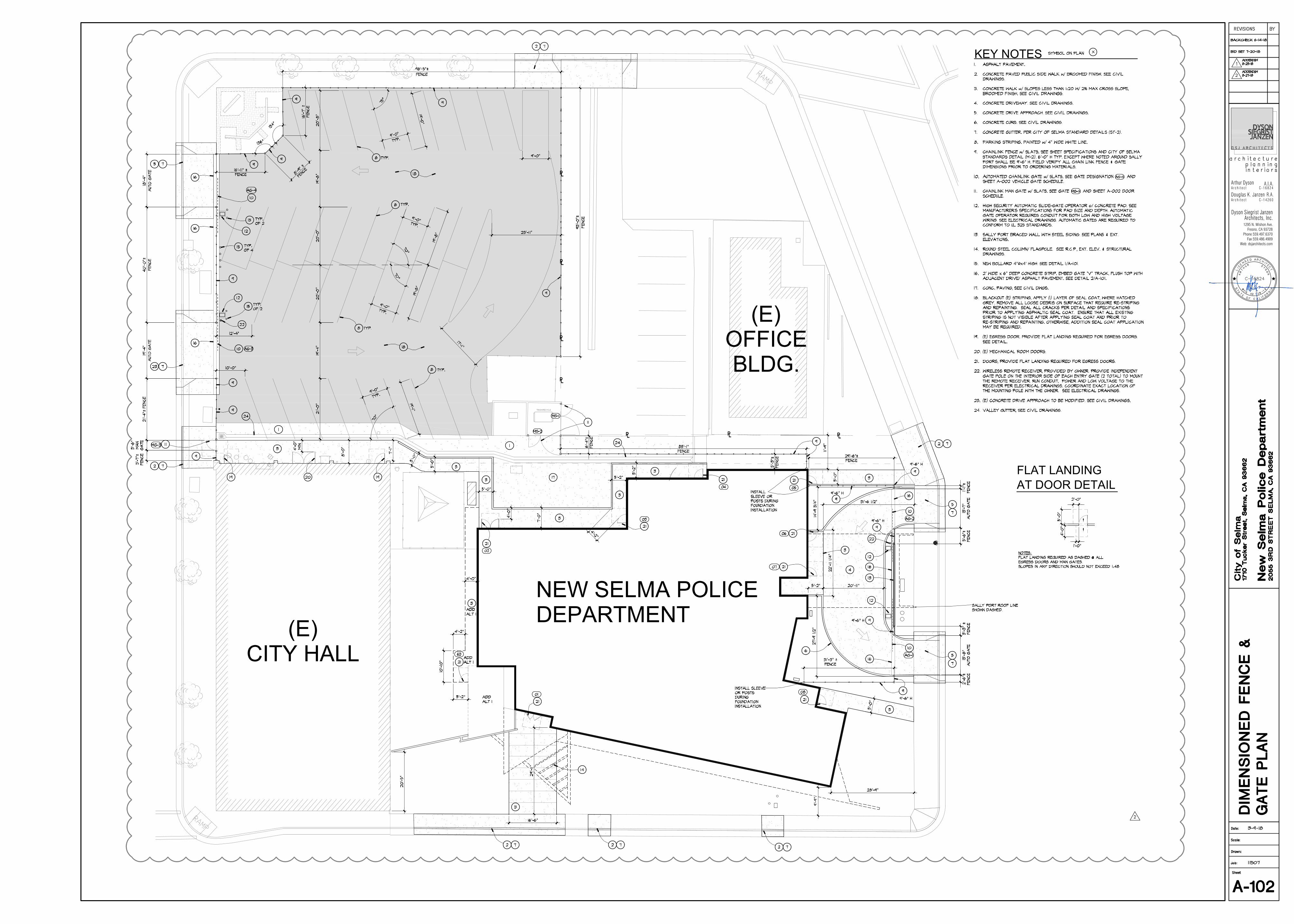
⅊ ⅊ ⅊
⅊
⅊
⅊
⅊
KEY NOTES
NEW SELMA POLICEDEPARTMENT(E)
CITY HALL
(E)OFFICEBLDG.
AT DOOR DETAILFLAT LANDING
1295 N. Wishon Ave.Fresno, CA 93728
Phone 559.497.6370Fax 559.486.4909
Web: dsjarchitects.com
Arthur DysonArchitect
A.I.A.C-16824
Douglas K. JanzenR.A.Architect C-14260
Dyson Siegrist JanzenArchitects, Inc.
AutoCAD SHX Text
RAMP
AutoCAD SHX Text
RAMP
AutoCAD SHX Text
96'-5"±
AutoCAD SHX Text
96'-5"±
AutoCAD SHX Text
96'-5"±
AutoCAD SHX Text
96'-5"±
AutoCAD SHX Text
96'-5"±
AutoCAD SHX Text
96'-5"±
AutoCAD SHX Text
96'-5"±
AutoCAD SHX Text
96'-5"±
AutoCAD SHX Text
SALLY PORT ROOF LINE SHOWN DASHED.
AutoCAD SHX Text
9'-6" H
AutoCAD SHX Text
93'-0"±
AutoCAD SHX Text
93'-0"±
AutoCAD SHX Text
93'-0"±
AutoCAD SHX Text
93'-0"±
AutoCAD SHX Text
93'-0"±
AutoCAD SHX Text
93'-0"±
AutoCAD SHX Text
93'-0"±
AutoCAD SHX Text
93'-0"±
AutoCAD SHX Text
9'-0"
AutoCAD SHX Text
9'-0"
AutoCAD SHX Text
9'-0"
AutoCAD SHX Text
18'-4"
AutoCAD SHX Text
18'-4"
AutoCAD SHX Text
18'-4"
AutoCAD SHX Text
18'-4"
AutoCAD SHX Text
18'-4"
AutoCAD SHX Text
18'-4"
AutoCAD SHX Text
18'-4"
AutoCAD SHX Text
18'-4"
AutoCAD SHX Text
18'-4"
AutoCAD SHX Text
18'-4"
AutoCAD SHX Text
9'-0"
AutoCAD SHX Text
9'-0"
AutoCAD SHX Text
9'-0"
AutoCAD SHX Text
9'-0"
AutoCAD SHX Text
9'-0"
AutoCAD SHX Text
9'-0"
AutoCAD SHX Text
9'-0"
AutoCAD SHX Text
9'-0"
AutoCAD SHX Text
9'-0"
AutoCAD SHX Text
01
AutoCAD SHX Text
63
AutoCAD SHX Text
02
AutoCAD SHX Text
03
AutoCAD SHX Text
04
AutoCAD SHX Text
05
AutoCAD SHX Text
06
AutoCAD SHX Text
07
AutoCAD SHX Text
08
AutoCAD SHX Text
MG-3
AutoCAD SHX Text
MG-1
AutoCAD SHX Text
MG-2
AutoCAD SHX Text
INSTALL SLEEVE OR POSTS DURING FOUNDATION INSTALLATION
AutoCAD SHX Text
INSTALL SLEEVE OR POSTS DURING FOUNDATION INSTALLATION
AutoCAD SHX Text
19'-4"
AutoCAD SHX Text
19'-4"
AutoCAD SHX Text
19'-4"
AutoCAD SHX Text
19'-4"
AutoCAD SHX Text
19'-4"
AutoCAD SHX Text
19'-4"
AutoCAD SHX Text
19'-4"
AutoCAD SHX Text
19'-4"
AutoCAD SHX Text
19'-4"
AutoCAD SHX Text
19'-4"
AutoCAD SHX Text
AG-4
AutoCAD SHX Text
AG-3
AutoCAD SHX Text
AG-2
AutoCAD SHX Text
AG-1
AutoCAD SHX Text
40'-0"±
AutoCAD SHX Text
40'-0"±
AutoCAD SHX Text
40'-0"±
AutoCAD SHX Text
40'-0"±
AutoCAD SHX Text
40'-0"±
AutoCAD SHX Text
40'-0"±
AutoCAD SHX Text
40'-0"±
AutoCAD SHX Text
40'-0"±
AutoCAD SHX Text
ADD ALT 1
AutoCAD SHX Text
9'-6" H
AutoCAD SHX Text
9'-6" H
AutoCAD SHX Text
NOTES: FLAT LANDING REQUIRED AS DASHED @ ALL EGRESS DOORS AND MAN GATES. SLOPES IN ANY DIRECTION SHOULD NOT EXCEED 1:48
AutoCAD SHX Text
1. ASPHALT PAVEMENT. ASPHALT PAVEMENT. 2. CONCRETE PAVED PUBLIC SIDE WALK w/ BROOMED FINISH. SEE CIVIL CONCRETE PAVED PUBLIC SIDE WALK w/ BROOMED FINISH. SEE CIVIL DRAWINGS. 3. CONCRETE WALK w/ SLOPES LESS THAN 1:20 W/ 2% MAX CROSS SLOPE, CONCRETE WALK w/ SLOPES LESS THAN 1:20 W/ 2% MAX CROSS SLOPE, BROOMED FINISH. SEE CIVIL DRAWINGS. 4. CONCRETE DRIVEWAY. SEE CIVIL DRAWINGS. CONCRETE DRIVEWAY. SEE CIVIL DRAWINGS. 5. CONCRETE DRIVE APPROACH. SEE CIVIL DRAWINGS. CONCRETE DRIVE APPROACH. SEE CIVIL DRAWINGS. 6. CONCRETE CURB. SEE CIVIL DRAWINGS. CONCRETE CURB. SEE CIVIL DRAWINGS. 7. CONCRETE GUTTER. PER CITY OF SELMA STANDARD DETAILS (ST-2). CONCRETE GUTTER. PER CITY OF SELMA STANDARD DETAILS (ST-2). (ST-2). . 8. PARKING STRIPING. PAINTED w/ 4" WIDE WHITE LINE. PARKING STRIPING. PAINTED w/ 4" WIDE WHITE LINE. 9. CHAINLINK FENCE w/ SLATS. SEE SHEET SPECIFICATIONS AND CITY OF SELMA CHAINLINK FENCE w/ SLATS. SEE SHEET SPECIFICATIONS AND CITY OF SELMA SPECIFICATIONS AND CITY OF SELMA STANDARDS DETAIL (M-2). 6'-0" H TYP. EXCEPT WHERE NOTED AROUND SALLY PORT SHALL BE 9'-6" H. FIELD VERIFY ALL CHAIN LINK FENCE & GATE DIMENSIONS PRIOR TO ORDERING MATERIALS. 10. AUTOMATED CHAINLINK GATE w/ SLATS. SEE GATE DESIGNATION AND AUTOMATED CHAINLINK GATE w/ SLATS. SEE GATE DESIGNATION AND SHEET A-002 VEHICLE GATE SCHEDULE. 11. CHAINLINK MAN GATE w/ SLATS. SEE GATE AND SHEET A-002 DOOR CHAINLINK MAN GATE w/ SLATS. SEE GATE AND SHEET A-002 DOOR A-002 DOOR DOOR SCHEDULE. 12. HIGH SECURITY AUTOMATIC SLIDE-GATE OPERATOR o/ CONCRETE PAD. SEE HIGH SECURITY AUTOMATIC SLIDE-GATE OPERATOR o/ CONCRETE PAD. SEE MANUFACTURER'S SPECIFICATIONS FOR PAD SIZE AND DEPTH. AUTOMATIC GATE OPERATOR REQUIRES CONDUIT FOR BOTH LOW AND HIGH VOLTAGE WIRING. SEE ELECTRICAL DRAWINGS. AUTOMATIC GATES ARE REQUIRED TO CONFORM TO UL 325 STANDARDS. 13. SALLY PORT BRACED WALL WITH STEEL SIDING. SEE PLANS & EXT. SALLY PORT BRACED WALL WITH STEEL SIDING. SEE PLANS & EXT. ELEVATIONS. 14. ROUND STEEL COLUMN/ FLAGPOLE. SEE R.C.P., EXT. ELEV. & STRUCTURAL ROUND STEEL COLUMN/ FLAGPOLE. SEE R.C.P., EXT. ELEV. & STRUCTURAL DRAWINGS. 15. NEW BOLLARD 4" x4' HIGH. SEE DETAIL 1/A-101. NEW BOLLARD 4" x4' HIGH. SEE DETAIL 1/A-101. . 16. 2' WIDE x 6" DEEP CONCRETE STRIP. EMBED GATE "V" TRACK, FLUSH TOP WITH 2' WIDE x 6" DEEP CONCRETE STRIP. EMBED GATE "V" TRACK, FLUSH TOP WITH ADJACENT DRIVE/ ASPHALT PAVEMENT. SEE DETAIL 2/A-101. 2/A-101. . 17. CONC. PAVING, SEE CIVIL DWGS. CONC. PAVING, SEE CIVIL DWGS. 18. BLACKOUT (E) STRIPING, APPLY (1) LAYER OF SEAL COAT, WHERE HATCHED BLACKOUT (E) STRIPING, APPLY (1) LAYER OF SEAL COAT, WHERE HATCHED GREY. REMOVE ALL LOOSE DEBRIS ON SURFACE THAT REQUIRE RE-STRIPING AND REPAINTING. SEAL ALL CRACKS PER DETAIL AND SPECIFICATIONS PRIOR TO APPLYING ASPHALTIC SEAL COAT. ENSURE THAT ALL EXISTING STRIPING IS NOT VISIBLE AFTER APPLYING SEAL COAT AND PRIOR TO RE-STRIPING AND REPAINTING. OTHERWISE, ADDITION SEAL COAT APPLICATION MAY BE REQUIRED. 19. (E) EGRESS DOOR. PROVIDE FLAT LANDING REQUIRED FOR EGRESS DOORS. (E) EGRESS DOOR. PROVIDE FLAT LANDING REQUIRED FOR EGRESS DOORS. SEE DETAIL. 20. (E) MECHANICAL ROOM DOORS. (E) MECHANICAL ROOM DOORS. 21. DOORS, PROVIDE FLAT LANDING REQUIRED FOR EGRESS DOORS. DOORS, PROVIDE FLAT LANDING REQUIRED FOR EGRESS DOORS. 22. WIRELESS REMOTE RECEIVER, PROVIDED BY OWNER. PROVIDE INDEPENDENT WIRELESS REMOTE RECEIVER, PROVIDED BY OWNER. PROVIDE INDEPENDENT GATE POLE ON THE INTERIOR SIDE OF EACH ENTRY GATE (2 TOTAL) TO MOUNT THE REMOTE RECEIVER. RUN CONDUIT, POWER AND LOW VOLTAGE TO THE RECEIVER PER ELECTRICAL DRAWINGS. COORDINATE EXACT LOCATION OF THE MOUNTING POLE WITH THE OWNER. SEE ELECTRICAL DRAWINGS. 23. (E) CONCRETE DRIVE APPROACH TO BE MODIFIED. SEE CIVIL DRAWINGS. (E) CONCRETE DRIVE APPROACH TO BE MODIFIED. SEE CIVIL DRAWINGS. 24. VALLEY GUTTER, SEE CIVIL DRAWINGS. VALLEY GUTTER, SEE CIVIL DRAWINGS.
AutoCAD SHX Text
2
AutoCAD SHX Text
AG-X
AutoCAD SHX Text
MG-X
AutoCAD SHX Text
9'-6" H
AutoCAD SHX Text
9'-6" H
AutoCAD SHX Text
ADD ALT 1
AutoCAD SHX Text
ADD ALT 1
AutoCAD SHX Text
TYP. OF 2
AutoCAD SHX Text
TYP. OF 2
AutoCAD SHX Text
TYP. OF 4
AutoCAD SHX Text
TYP.
AutoCAD SHX Text
TYP.
AutoCAD SHX Text
TYP.
AutoCAD SHX Text
TYP.
AutoCAD SHX Text
SYMBOL ON PLAN
AutoCAD SHX Text
A-102
AutoCAD SHX Text
DIMENSIONED FENCE & GATE PLAN
AutoCAD SHX Text
1710 Tucker Street, Selma, CA 93662
AutoCAD SHX Text
New Selma Police Department
AutoCAD SHX Text
2055 3RD STREET SELMA, CA 93662
AutoCAD SHX Text
City of Selma
AutoCAD SHX Text
Date:
AutoCAD SHX Text
REVISIONS
AutoCAD SHX Text
BY
AutoCAD SHX Text
Scale:
AutoCAD SHX Text
Drawn:
AutoCAD SHX Text
Job:
AutoCAD SHX Text
Sheet
AutoCAD SHX Text
3-9-18
AutoCAD SHX Text
11507
AutoCAD SHX Text
L
AutoCAD SHX Text
I
AutoCAD SHX Text
C
AutoCAD SHX Text
E
AutoCAD SHX Text
N
AutoCAD SHX Text
S
AutoCAD SHX Text
E
AutoCAD SHX Text
D
AutoCAD SHX Text
A
AutoCAD SHX Text
R
AutoCAD SHX Text
C
AutoCAD SHX Text
H
AutoCAD SHX Text
I
AutoCAD SHX Text
T
AutoCAD SHX Text
E
AutoCAD SHX Text
T
AutoCAD SHX Text
F
AutoCAD SHX Text
C
AutoCAD SHX Text
I
AutoCAD SHX Text
F
AutoCAD SHX Text
O
AutoCAD SHX Text
S
AutoCAD SHX Text
T
AutoCAD SHX Text
E
AutoCAD SHX Text
O
AutoCAD SHX Text
A
AutoCAD SHX Text
L
AutoCAD SHX Text
R
AutoCAD SHX Text
N
AutoCAD SHX Text
I
AutoCAD SHX Text
A
AutoCAD SHX Text
T
AutoCAD SHX Text
A
AutoCAD SHX Text
C-16824
AutoCAD SHX Text
A
AutoCAD SHX Text
R
AutoCAD SHX Text
T
AutoCAD SHX Text
H
AutoCAD SHX Text
U
AutoCAD SHX Text
R
AutoCAD SHX Text
9
AutoCAD SHX Text
1
AutoCAD SHX Text
8
AutoCAD SHX Text
2
AutoCAD SHX Text
2
AutoCAD SHX Text
0
AutoCAD SHX Text
N.
AutoCAD SHX Text
R
AutoCAD SHX Text
R
AutoCAD SHX Text
E
AutoCAD SHX Text
D
AutoCAD SHX Text
Y
AutoCAD SHX Text
S
AutoCAD SHX Text
O
AutoCAD SHX Text
N
AutoCAD SHX Text
C
AutoCAD SHX Text
architecture
AutoCAD SHX Text
planning
AutoCAD SHX Text
interiors
AutoCAD SHX Text
BACKCHECK 6-14-18
AutoCAD SHX Text
BID SET 7-20-18
AutoCAD SHX Text
1
AutoCAD SHX Text
ADDENDUM 8-23-18
AutoCAD SHX Text
2
AutoCAD SHX Text
ADDENDUM 8-27-18

1295 N. Wishon Ave.Fresno, CA 93728
Phone 559.497.6370Fax 559.486.4909
Web: dsjarchitects.com
Arthur Dyson Architect
A.I.A.C-16824
Robert C. Siegrist
Douglas K. Janzen
architectureplanninginteriors
Architect C-9651A.I.A.
R.A.Architect C-14260
Dyson Siegrist JanzenArchitects, Inc.

1295 N. Wishon Ave.Fresno, CA 93728
Phone 559.497.6370Fax 559.486.4909
Web: dsjarchitects.com
Arthur Dyson Architect
A.I.A.C-16824
Robert C. Siegrist
Douglas K. Janzen
architectureplanninginteriors
Architect C-9651A.I.A.
R.A.Architect C-14260
Dyson Siegrist JanzenArchitects, Inc.
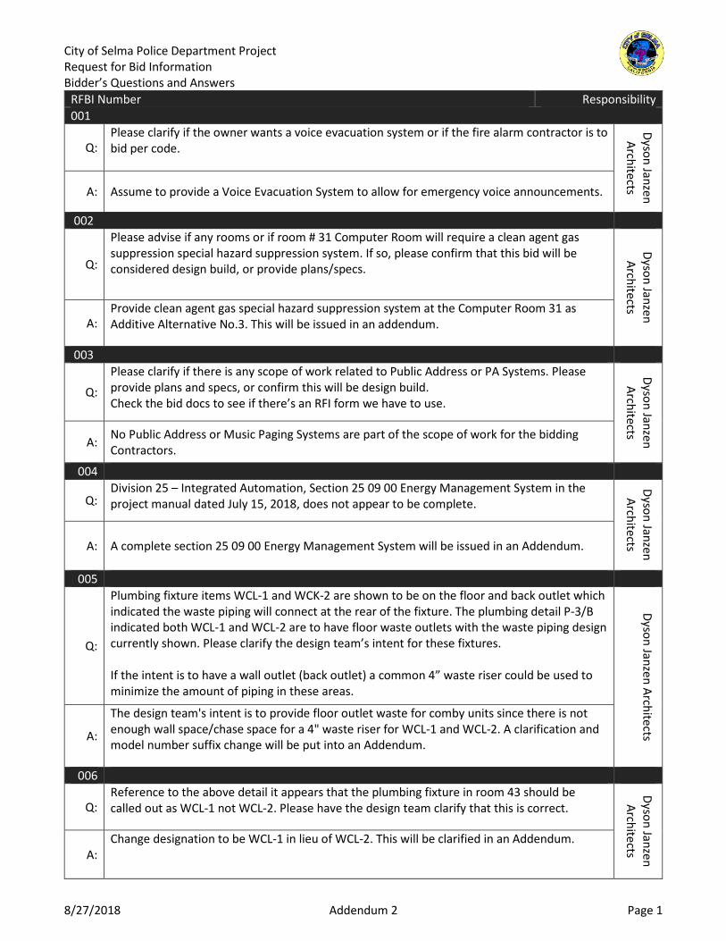
City of Selma Police Department Project Request for Bid Information Bidder’s Questions and Answers
8/27/2018 Addendum 2 Page 1
RFBI Number Responsibility 001
Q: Please clarify if the owner wants a voice evacuation system or if the fire alarm contractor is to bid per code.
Dyson Janzen Architects A: Assume to provide a Voice Evacuation System to allow for emergency voice announcements.
002
Q:
Please advise if any rooms or if room # 31 Computer Room will require a clean agent gas suppression special hazard suppression system. If so, please confirm that this bid will be considered design build, or provide plans/specs.
Dyson Janzen Architects
A: Provide clean agent gas special hazard suppression system at the Computer Room 31 as Additive Alternative No.3. This will be issued in an addendum.
003
Q:
Please clarify if there is any scope of work related to Public Address or PA Systems. Please provide plans and specs, or confirm this will be design build. Check the bid docs to see if there’s an RFI form we have to use.
Dyson Janzen Architects A: No Public Address or Music Paging Systems are part of the scope of work for the bidding
Contractors.
004
Q: Division 25 – Integrated Automation, Section 25 09 00 Energy Management System in the project manual dated July 15, 2018, does not appear to be complete.
Dyson Janzen Architects A: A complete section 25 09 00 Energy Management System will be issued in an Addendum.
005
Q:
Plumbing fixture items WCL-1 and WCK-2 are shown to be on the floor and back outlet which indicated the waste piping will connect at the rear of the fixture. The plumbing detail P-3/B indicated both WCL-1 and WCL-2 are to have floor waste outlets with the waste piping design currently shown. Please clarify the design team’s intent for these fixtures. If the intent is to have a wall outlet (back outlet) a common 4” waste riser could be used to minimize the amount of piping in these areas.
Dyson Janzen Architects A:
The design team's intent is to provide floor outlet waste for comby units since there is not enough wall space/chase space for a 4" waste riser for WCL-1 and WCL-2. A clarification and model number suffix change will be put into an Addendum.
006
Q: Reference to the above detail it appears that the plumbing fixture in room 43 should be called out as WCL-1 not WCL-2. Please have the design team clarify that this is correct.
Dyson Janzen Architects A:
Change designation to be WCL-1 in lieu of WCL-2. This will be clarified in an Addendum.

City of Selma Police Department Project Request for Bid Information Bidder’s Questions and Answers
8/27/2018 Addendum 2 Page 2
RFBI Number Responsibility 007
Q:
E101, Key Note #26: Please clarify existing cable types and quantities. Clarify number of conduits, conduit size, and length to be replaced. E-401, Key Note #4: Please provide specification for the telephone “Trunk Cable” to be installed. E-401, Key Note #28: Please provide clarification for “Security Monitoring Station” and what is to be provided in this contract. E-401, Key Note #29: Are CCTV Wall Monitors to be provided and installed in this contract? If so, provide specification.
Dyson Janzen Architects A: CCTV’s are provided by separate Vendor. Refer to revised Sheets E-101 and E-401, under Addendum No.1, for clarifications.
008
Q:
The plumbing fixture schedule on plan sheet P-5 indicates two individual drain receptors for both the roof and overflow drains. Reference to plan sheet A-401, keynote #15 indicates a combination roof and overflow drain receptor is to be used. Please clarify which drain specification is to be used. The combination roof and overflow drain receptor will be the most economical installation for the owner or budget concerns. See attached submittal cutsheet for acceptable combination roof drain receptor used on past projects.
Dyson Janzen Architects A: We take no exception to the Contractor's proposed solution to provide a combination roof and overflow drain assembly to match the Architectural plans. This will be clarified in an Addendum.
009
Q: Plan sheet P-5 (plumbing fixture schedule) references a specification for water hammer but the project plumbing drawings do not indicate any locations for these items. Please provide a detailed list of the locations that the design team intendent for these items to be installed.
Dyson Janzen Architects A: Water hammer arrestor locations will be clarified in an Addendum.
010
Q:
Following Plan sheets call for details that do not exist: - Keynote #25/A-202 Calls for 18/A-801 - KN#30/A-601 Calls for 18/A-108 - KN#29/A-601 Calls for 25/A-108 - KN#36/A-602 Calls for A-205 - 3/A-501 Calls for 3/A-803 - 3/A-501 Calls for 4/A-803 - 3/A-501 Calls for 11/A-804 - 8/S-703 Calls for 2/S-604 - 9/S-703 Calls for 1/S-604 - 7/S-800 Calls for 4/S-603
Dyson Janzen Architects
A:
Replace Keynote 25/A-202 reference to detail 18/A-801 with details A&25/A-801. Replace Keynote 30/A-601 reference to detail 18/A-108 with details A&25/A-801. Replace Keynote 29/A-601 reference to detail 25/A-108 with details A&25/A-801. Replace Keynote 36/A-602 reference to detail A/205 with detail B/A-602. Details 3/ A-803, 4/A-803, 11/A-804 are issued in an Addendum See Structural Responses clouded on next sheet.

City of Selma Police Department Project Request for Bid Information Bidder’s Questions and Answers
8/27/2018 Addendum 2 Page 3
RFBI Number Responsibility 011
Q:
Specifications Bid Proposal Form - 00 11 16; Sect. #3. Calls for an 'Agreement to Be Bound' to be included in the Long Bid Form. List of Subcontractors (page 12 0f 24) notes; 'The Bidder and all Subcontractors, at any and all tiers, shall be required to sign and submit to the City an Agreement to Be Bound to the CWA that is part of these Contract Documents. Come bid day, decision to select subcontractors comes 10-30 minutes before time of bid submission. Request to submit 'Agreement to Be Bound' documents 24 Hours after Bid day.
City of Selma
A: Yes, it is acceptable to submit 'Agreement to Be Bound' documents 24 hours after bid day; no later than 2:00 pm Friday, August 31, 2018
012
Q:
Bid Proposal Form 00 11 16 - Subcontractor List calls for the following Information to be included at time of Bid; Name: Address: City & State only. (Complete Address) Telephone Number: Email Address: State Contractor's License No. and Class: Department of Industrial Relations Registration No.: Portion of Work: Request to submit the information in RED [bold] 24 Hours after time of Bid.
City of Selma
A: The contractor’s suggestion is acceptable. 013
Q: Reference to detail on plan sheet X101 indicates that a protective enclosure is optional and in freeze prone areas freeze protection is recommended. Is either one of these requirements needed for the backflow preventers on this project?
Dyson Janzen Architects A:
The thermal expansion joint referenced in note 7 in detail [J/X101] IS required. The protective enclosure referenced in note 9 in detail [J/X101] is not required, since Selma is not a freeze-prone area.
014
Q: The plumbing fixture schedule item SH-1 indicates that a Kohler K-9136 shower drain is to be used for this fixture but, plan sheet detail A/P-4 also indicates a FD-1 floor drain for this fixture item. Please clarify the correct shower drain to be used for SH-1
Dyson Janzen Architects A: Provide the shower drain indicated under SH-1 and remove the FD-1. This will be clarified in
an Addendum. 015
Q:
There are several IDU equipment items that are shown on plan sheet M-1 but do not indicate the need for condensate piping on the plumbing drawings. Please show this piping and termination of same or confirm that IDU equipment items 19A, 19B, 19C, and 17 do not require any condensate piping.
Dyson Janzen Architects
A: IDU's require condensate piping. Provide condensate piping for IDU's 19A, 19B, 19C, and 17. This will be clarified in an Addendum.
016
Q:
With reference to the required utility fees and assessments (ex. Cal Water, SKF Sewer) will the owner be responsible for these costs? If not and it will be the responsibility of the contractor please provide a tabulation of these costs so all bidders can include this amount within their bid.
City of Selm
a
A: The City will pay those fees directly.

City of Selma Police Department Project Request for Bid Information Bidder’s Questions and Answers
8/27/2018 Addendum 2 Page 4
RFBI Number Responsibility 017
Q: Specifications Table of Contents lists Specification Section 12 4813 - Floor Mats and Frames. Specifications do not include a Section for 12 4813 - Floor Mats and Frames. Please advise if this Section applies to the project. If so, please provide Specification Section 12 4813.
Dyson Janzen Architects A:
Section 124813 Floor Mats and Frames have been removed from the project. Please remove the heading from Table of Contents.
018
Q: Plan sheet S-702 detail #6(attached) notes a C.J.P. Weld. However, the symbol represents a Fillet Weld. Please clarify.
Dyson Janzen Architects A: 2018-08-15 Disregard the C.J.P. note on the tail of the weld. 1/4" fillet all around will be
adequate.
019
Q: Plan sheet A703 Keynote #36 states Tapered Rigid Insulation Roof Cricket. Slope surface Min. 1/2" per Ft. Min. U.N.O. Slope Valleys 1/8" Per F.T. Secure w/Screws& Plates to Roof Deck. Anything greater than 6" of space will require Fire Sprinklers Please advise.
Dyson Janzen Architects A: Roof crickets are constructed entirely of non-combustible material.
020
Q:
The Salsbury Industries website for the 61000 series lockers notes "16-gauge", however it doesn't state what components are 16-gauge. We believe only the frame and the door surface are16 gauge with the intermediate side panels, back panels, top panels, and shelves being 24-gauge. It also appears that sloped tops are not required for this project. If that is confirmed, for this type of installation, we would typically see the very top shelf that forms the top exposed portion of the locker be 16-gauge.
• Please confirm gauge thickness of metal for locker sides, backs and shelves. • Please confirm gauge thickness of metal for the locker tops if sloped tops are not
required for this project.
Dyson Janzen Architects
A: All components of the locker to be made of 16ga. metal including intermediate side panels, back panels, top panels, shelves and tops.
021
Q:
Specification 07 5216 (SBS)Modified Bituminous Membrane Roofing Sect 3.3 - Field Quality Control; A. Notes - General: RCI Certified Roof Inspector shall be present at all times when roofing materials are being applied. Can this requirement be waived? An RRO or Inspector will add a lot of cost to this project(Min.$1,200/day). The roofing manufacturer will make Interim & Final Inspections. Based on these Inspections they will Issue a 20 year NDL Warranty. This should be adequate for a project this size. Please advise.
Dyson Janzen Architects A:
Revise specification section 075216, part 3.3-Field Quality Control, item A. General to read "Manufacturer's representative shall provide inspection at each phase of the installation and a comprehensive final inspection after completion of the roof system. All application errors must be addressed and final punch list completed." RCI Certified roof inspector is not required to be present at all times.

City of Selma Police Department Project Request for Bid Information Bidder’s Questions and Answers
8/27/2018 Addendum 2 Page 5
RFBI Number Responsibility 022
Q:
Site Plan Sheet A-101 Keynotes 3, 11-15, and 40 relating to On-Site Concrete Improvements indicate ' See Civil Drawings '. Civil Drawings do not call out by Keynote or Detail the On-Site Concrete Improvements. Please provide On-Site Improvement Plans with Details for the project.
Dyson Janzen Architects
A: Please refer to C-301, C-302, A-E&L/X102 and Selma City standard details.

REQUEST FOR BID INFORMATION
Page 1 of 1
Vanir Construction Management, Inc.2444 Main Street, Suite 130 Fresno, CA 93721 Phone: 559.496.0536 Fax: 559.860.0173 Owner’s Representative
To: Vanir Construction Management, Inc. RFBI No.: 001
From:(Contractor’s Name):
George San Mateo at HCI Systems Inc
3742 W Gettysburg Ave, Ste 102Fresno, Ca 93722 559-233-2008 Date: 7/23/18
Project: City of Selma Police Department
Subject: Fire Alarm
Drawings: N/A Specifications: N/A Division No.: N/A
Description Of Problem / Clarification / Information Required:
Please clarify if the owner wants a voice evacuation system or if the fire alarm contractor is to bid per code.
Contractor’s Proposed Solution:
By: George San Mateo
Name Signature
Answer required by:
Response:Assume to provide a Voice Evacuation System to allow for emergency voice announcements.
Respondent: Richard J Hardin
Name Signature
Firm: HDE Title: Date: 07/30/2018
Reviewed by: Stefanie Pedler, Project Coordinator Date: 8/3/18

REQUEST FOR BID INFORMATION
Page 1 of 1
Vanir Construction Management, Inc. 2444 Main Street, Suite 130 ׀ Fresno, CA 93721 Phone: 559.496.0536 ׀ Fax: 559.860.0173
Owner’s Representative
To: Vanir Construction Management, Inc. RFBI No.: 002
From: (Contractor’s Name):
George San Mateo at HCI Systems Inc
3742 W Gettysburg Ave, Ste 102 Fresno, Ca 93722 559-233-2008 Date: 7/23/18
Project: City of Selma Police Department
Subject: Clean Agent System
Drawings: N/A Specifications: N/A Division No.: N/A
Description Of Problem / Clarification / Information Required:
Please advise if any rooms or if room # 31 Computer Room will require a clean agent gas suppression special hazard suppression system. If so, please confirm that this bid will be considered design build, or provide plans/specs.
Contractor’s Proposed Solution:
By: George San Mateo
Name Signature
Answer required by:
Response:
Provide clean agent gas special hazard suppression system at the Computer Room 31 as Additive Alternative No.3.
Respondent: Mayuko Russell
Name Signature
Firm: Title: Date:
Reviewed by: Date:
ignature
Dyson Janzen Architects Project Manager 8-1-2018
This will be issued in an addendum.
Stefanie Pedler, Project Coordinator 8/20/18

REQUEST FOR BID INFORMATION
Page 1 of 1
Vanir Construction Management, Inc.2444 Main Street, Suite 130 Fresno, CA 93721 Phone: 559.496.0536 Fax: 559.860.0173 Owner’s Representative
To: Vanir Construction Management, Inc. RFBI No.: 003
From:(Contractor’s Name):
George San Mateo at HCI Systems Inc
3742 W Gettysburg Ave, Ste 102Fresno, Ca 93722 559-233-2008 Date: 7/23/18
Project: City of Selma Police Department
Subject: Public Address
Drawings: N/A Specifications: N/A Division No.: N/A
Description Of Problem / Clarification / Information Required:
Please clarify if there is any scope of work related to Public Address or PA Systems. Please provide plans and specs, or confirm this will be design build.Check the bid docs to see if there’s an RFI form we have to use.
Contractor’s Proposed Solution:
By: George San Mateo
Name Signature
Answer required by:
Response:No Public Address or Music Paging Systems are part of the scope of work for the bidding Contractors.
Respondent: Richard J Hardin
Name Signature
Firm: HDE Title: Date: 07/30/2018
Reviewed by: Stefanie Pedler, Project Coordinator Date: 8/3/18

REQUEST FOR BID INFORMATION
Page 1 of 1
Vanir Construction Management, Inc. 2444 Main Street, Suite 130 ׀ Fresno, CA 93721 Phone: 559.496.0536 ׀ Fax: 559.860.0173
Owner’s Representative
To: Vanir Construction Management, Inc. RFBI No.:
From: (Contractor’s Name): Bedard Controls, Inc. Date: July 27, 2018
Project: City of Selma Police Department
Subject: Project Manual – Division 25 – Integrated Automation
Drawings: Specifications: Division No.:
Description Of Problem / Clarification / Information Required: Division 25 – Integrated Automation, Section 25 09 00 Energy Management System in the project manual dated July 15, 2018, does not appear to be complete.
Contractor’s Proposed Solution: Please publish complete Division 25.
By: Keith Harris
Name Signature
Answer required by: August 1, 2018
Response:
Respondent:
Name Signature
Firm: Title: Date:
Reviewed by: Date:
004
A complete section 25 09 00 Energy Management System will be issued in anAddendum.
8-8-2018Dyson Janzen Architects Project Architect
Mayuko Russell
i t
Stefanie Pedler, Project Coordinator 8/20/18

005
The design team's intent is to provide floor outlet waste for comby units since there is notenough wall space/chase space for a 4" waste riser for WCL-1 and WCL-2. A clarificationand model number suffix change will be put into an Addendum.
Dave Oustad
Lawrence Engr. Group Sr. Mech. Engr. 8-13-18
Mayuko Russell 8-15-18

009
Change designation to be WCL-1 in lieu of WCL-2. This will beclarified in an Addendum.
Dave Oustad
Lawrence Engr. Group Sr. Mech Engr. 8-21-18
Stefanie Pedler, Project Coordinator 8/22/18

Request for Bid Information
RFBI # 007
CCTV’s are provided by separate Vendor.Refer to revised Sheets E-101 and E-401, under Addendum No.1, forclarifications.
Richard J Hardin P.E. 08/22/2018
Mayuko Russell, Dyson Janzen Architects8-22-18

008
We take no exception to the Contractor's proposed solution to provide a combination roof andoverflow drain assembly to match the Architectural plans. This will be clarified in anAddendum.
Dave Oustad
Lawrence Engr. Group Sr. Mech. Engr. 8-13-18
Mayuko Russell 8-15-18


009
Water hammer arrestor locations will be clarified in an Addendum.
Dave Oustad
Lawrence Engr. Group Sr. Mech. Engr. 8-13-18
Mayuko Russell 8-15-2018

REQUEST FOR BID INFORMATION
Page 1 of 1
Vanir Construction Management, Inc. 2444 Main Street, Suite 130 ׀ Fresno, CA 93721 Phone: 559.496.0536 ׀ Fax: 559.860.0173
Owner’s Representative
To: Vanir Construction Management, Inc. RFBI No.:
From: (Contractor’s Name): Date:
Project: City of Selma Police Department
Subject:
Drawings: Specifications: Division No.:
Description Of Problem / Clarification / Information Required:
Contractor’s Proposed Solution:
By:
Name Signature
Answer required by:
Response:
Respondent:
Name Signature
Firm: Title: Date:
Reviewed by: Date:
01
08/10/2018
Missing Details
Seals Construction
Architectural & Structutral
See attached.
Danny Orozco
08/15/2018
010
Responses to Architectural References:
Replace Keynote 25/A-202 reference to detail 18/A-801 with details A&25/A-801.Replace Keynote 30/A-601 reference to detail 18/A-108 with details A&25/A-801.Replace Keynote 29/A-601 reference to detail 25/A-108 with details A&25/A-801.Replace Keynote 36/A-602 reference to detail A/205 with detail B/A-602Details 3/ A-803, 4/A-803, 11/A-804 are issued in an Addendum
Mayuko Russell,Dyson Janzen Architects 8-15-2018
See Structural Responses clouded on next sheet.
re
Mayuko Russell
Dyson Janzen Architects Project Architect 8-27-2018
Stefanie Pedler, Project Coordinator 8/27/18

REFERENCE SHOULD BE 9/S-703
REFERENCE SHOULD BE 8/S-703
REFERENCE SHOULD BE 4/S-601
SEE CLOUDED CORRECTIONS ABOVE
Jim Hansen, SEOR
D CORRECTIONS ABOVE
EORORORORRORRRORORRRORORORRORORORRORORORORORORORRRRROROOOROOOOOOOOOROOOOOOOOOOOOOOOOOOOOOOOOOOOOOO

REQUEST FOR BID INFORMATION
Page 1 of 1
Vanir Construction Management, Inc. 2444 Main Street, Suite 130 ׀ Fresno, CA 93721 Phone: 559.496.0536 ׀ Fax: 559.860.0173
Owner’s Representative
To: Vanir Construction Management, Inc. RFBI No.:
From: (Contractor’s Name): Date:
Project: City of Selma Police Department
Subject:
Drawings: Specifications: Division No.:
Description Of Problem / Clarification / Information Required:
Contractor’s Proposed Solution:
By:
Name Signature
Answer required by:
Response:
Respondent:
Name Signature
Firm: Title: Date:
Reviewed by: Date:
02
08/13/2018
Agreement to Be Bound
00 11 16 - Bid Proposal Form
Specifications Bid Proposal Form - 00 11 16; Sect. #3. Calls for an 'Agreement to Be Bound' to beincluded in the Long Bid Form. List of Subcontractors (page 12 0f 24) notes; 'The Bidder and allSubcontractors, at any and all tiers, shall be required to sign and submit to the City an Agreementto Be Bound to the CWA that is part of these Contract Documents.Come bid day, decision to selectsubcontractors comes 10-30 minutes before timeof bid submission.Request to submit 'Agreement to BeBound' documents 24 Hours after Bid day.
Danny Orozco
08/15/2018
011
Yes, it is acceptable to submit 'Agreement to Be Bound' documents 24 hours after bid day.
Chief Greg Garner
City of Selma Chief of Police 8/20/18
Stefanie Pedler, Project Coordinator 8/21/18

REQUEST FOR BID INFORMATION
Page 1 of 1
Vanir Construction Management, Inc. 2444 Main Street, Suite 130 ׀ Fresno, CA 93721 Phone: 559.496.0536 ׀ Fax: 559.860.0173
Owner’s Representative
To: Vanir Construction Management, Inc. RFBI No.:
From: (Contractor’s Name): Date:
Project: City of Selma Police Department
Subject:
Drawings: Specifications: Division No.:
Description Of Problem / Clarification / Information Required:
Contractor’s Proposed Solution:
By:
Name Signature
Answer required by:
Response:
Respondent:
Name Signature
Firm: Title: Date:
Reviewed by: Date:
03
08/13/2018
List of Subcontractors
Seals Construction
Danny Orozco
08/15/2018
00 11 16
Name:Address:City & State only.(Complete Address)Telephone Number:Email Address:State Contractor's License No. and Class: Department of Industrial Relations Registration No.:Portion of Work:
Bid Proposal Form 00 11 16 - Subcontractor List calls for the following Information to be included at time of Bid;
Request to submit the information in RED 24 Hours after time of Bid.
012
The contractor’s suggestion is acceptable.
Chief Greg Garner
City of Selma Chief of Police 8/21/18
Stefanie Pedler, Project Coordinator 8/21/18

013
The thermal expansion joint referenced innote 7 in detail [J/X101] IS required.The protective enclosure referenced in note9 in detail [J/X101] is not required, sinceSelma is not a freeze-prone area.
Zachary Hockett
Blair, Church, & Flynn Project Engineer 8/21/18
Mayuko Russell 8-22-2018

014
Provide the shower drain indicated under SH-1 and remove the FD-1. This will be clarifiedin an Addendum.
Dave Oustad
LEG 8-21-18
Mayuko Russell 8-21-18

015
IDU's require condensate piping. Provide condensate piping for IDU's 19A, 19B, 19C,and 17. This will be clarified in an Addendum.
Dave Oustad
LEG 8-21-18
Mayuko Russell 8-21-18

016
The City will pay those fees directly.
Isaac Moreno
City of Selma Interim City Manager 8/27/18
Stefanie Pedler, Project Coordinator 8/27/18

REQUEST FOR BID INFORMATION
Page 1 of 1
Vanir Construction Management, Inc. 2444 Main Street, Suite 130 ׀ Fresno, CA 93721 Phone: 559.496.0536 ׀ Fax: 559.860.0173
Owner’s Representative
To: Vanir Construction Management, Inc. RFBI No.:
From: (Contractor’s Name): Date:
Project: City of Selma Police Department
Subject:
Drawings: Specifications: Division No.:
Description Of Problem / Clarification / Information Required:
Contractor’s Proposed Solution:
By:
Name Signature
Answer required by:
Response:
Respondent:
Name Signature
Firm: Title: Date:
Reviewed by: Date:
04
08/14/2018
12 4813 - Floor Mats and Frames
Seals Construction
Specifications Table of Contents lists Specification Section 12 4813 - Floor Mats and Frames.Specifications do not include a Section for 12 4813 - Floor Mats and Frames.
Please advise if this Section applies to the project. If so, please provideSpecification Section 12 4813.
Danny Orozco
08/16/2018
12 4813
017
Section 124813 Floor Mats and Frames have been removed from the project.Please remove the heading from Table of Contents.
Mayuko Russell
ature
Dyson Janzen Architects Project Architect 8-15-2018
Stefanie Pedler, Project Coordinator 8/20/18

REQUEST FOR BID INFORMATION
Page 1 of 1
Vanir Construction Management, Inc. 2444 Main Street, Suite 130 ׀ Fresno, CA 93721 Phone: 559.496.0536 ׀ Fax: 559.860.0173
Owner’s Representative
To: Vanir Construction Management, Inc. RFBI No.:
From: (Contractor’s Name): Date:
Project: City of Selma Police Department
Subject:
Drawings: Specifications: Division No.:
Description Of Problem / Clarification / Information Required:
Contractor’s Proposed Solution:
By:
Name Signature
Answer required by:
Response:
Respondent:
Name Signature
Firm: Title: Date:
Reviewed by: Date:
Structural Beam Detail
05
08/14/2018Kasco Fab Inc.
6/S-702
Plan sheet S-702 detail #6(attached) notes a C.J.P. Weld. However, the symbol represents a Fillet Weld.
Please clarify.
Charles Evans
08/16/2018
018
2018-08-15
Disregard the C.J.P. note on the tail of the weld. 1/4" fillet all around will be adequate.
Jim Hansen, SEOR
Mayuko Russell 8-15-2018


REQUEST FOR BID INFORMATION
Page 1 of 1
Vanir Construction Management, Inc. 2444 Main Street, Suite 130 ׀ Fresno, CA 93721 Phone: 559.496.0536 ׀ Fax: 559.860.0173
Owner’s Representative
To: Vanir Construction Management, Inc. RFBI No.:
From: (Contractor’s Name): Date:
Project: City of Selma Police Department
Subject:
Drawings: Specifications: Division No.:
Description Of Problem / Clarification / Information Required:
Contractor’s Proposed Solution:
By:
Name Signature
Answer required by:
Response:
Respondent:
Name Signature
Firm: Title: Date:
Reviewed by: Date:
06
08/16/2018Jerico Fire Protection, Inc.
KN#36/A-703
Plan sheet A703 Keynote #36 states Tapered Rigid Insulation Roof Cricket. Slope surface Min. 1/2" per Ft. Min. U.N.O.Slope Valleys 1/8" Per F.T.Secure w/Screws& Plates to Roof Deck. Anything greater than 6" of space will require FireSprinklers
Please advise.
Bruce Jordan
08/21/2018
Fire Sprinklers
019
Roof crickets are constructed entirely of non-combustible material.
Mayuko Russell
Dyson Janzen Architects Project Architect 8-27-2018
Stefanie Pedler, Project Coordinator 8/27/18

REQUEST FOR BID INFORMATION
Page 1 of 1
Vanir Construction Management, Inc. 2444 Main Street, Suite 130 ׀ Fresno, CA 93721 Phone: 559.496.0536 ׀ Fax: 559.860.0173
Owner’s Representative
To: Vanir Construction Management, Inc. RFBI No.:
From: (Contractor’s Name): Date:
Project: City of Selma Police Department
Subject:
Drawings: Specifications: Division No.:
Description Of Problem / Clarification / Information Required:
Contractor’s Proposed Solution:
By:
Name Signature
Answer required by:
Response:
Respondent:
Name Signature
Firm: Title: Date:
Reviewed by: Date:
07
08/16/2018SSEC
10 5113Metal Lockers
The Salsbury Industries website for the 61000 series lockers notes "16-gauge", however itdoesn't state what components are 16-gauge. We believe only the frame and the door surface are16 gauge with the intermediate side panels, back panels, top panels, and shelves being 24-gauge. It also appears that sloped tops are not required for this project. If that is confirmed, for this type of installation, we would typically see the very top shelf that forms the top exposedportion of the locker be 16-gauge.
Please confirm gauge thickness of metal for locker sides, backs and shelves.
Please confirm gauge thickness of metal for the locker tops if sloped tops arenot required for this project.
Tony Hellus
08/21/2018
Metal Locker Body Gauge Requirement
020
All components of the locker to be made of 16ga. metal including intermediate side panels,back panels, top panels, shelves and tops.
8-20-2018
Mayuko Russell
Signature
Dyson Janzen Architects Project Architect
Stefanie Pedler, Project Coordinator 8/20/18

REQUEST FOR BID INFORMATION
Page 1 of 1
Vanir Construction Management, Inc. 2444 Main Street, Suite 130 ׀ Fresno, CA 93721 Phone: 559.496.0536 ׀ Fax: 559.860.0173
Owner’s Representative
To: Vanir Construction Management, Inc. RFBI No.:
From: (Contractor’s Name): Date:
Project: City of Selma Police Department
Subject:
Drawings: Specifications: Division No.:
Description Of Problem / Clarification / Information Required:
Contractor’s Proposed Solution:
By:
Name Signature
Answer required by:
Response:
Respondent:
Name Signature
Firm: Title: Date:
Reviewed by: Date:
08
08/16/2018Graham Prewett, Inc.
07 5216
Specification 07 5216 (SBS)Modified Bituminous Membrane Roofing Sect 3.3 - Field Quality Control; A. Notes - General: RCI Certified Roof Inspector shall be present at all times when roofing materials are being applied.
Can this requirement be waived? An RRO or Inspector will add alot of cost to thisproject(Min.$1,200/day). The roofing manufacturer will make Interim & Final Inspections.Based on these Inspections they will Issue a 20 year NDL Warranty. This should be adequatefor a project this size.
Please advise.
Rick Chacon
08/21/2018
Certified Roofing Inspector
(SBS) Modified Bituminous Membrane Roofing
021
Revise specification section 075216, part 3.3-Field Quality Control, item A. General to read"Manufacturer's representative shall provide inspection at each phase of the installation and acomprehensive final inspection after completion of the roof system. All application errors must beaddressed and final punch list completed."
RCI Certified roof inspector is not required to be present at all times.
Signature
Mayuko Russell
Dyson Janzen Architects Project Architect 8-20-2018
Stefanie Pedler, Project Coordinator 8/20/18

REQUEST FOR BID INFORMATION
Page 1 of 1
Vanir Construction Management, Inc. 2444 Main Street, Suite 130 ׀ Fresno, CA 93721 Phone: 559.496.0536 ׀ Fax: 559.860.0173
Owner’s Representative
To: Vanir Construction Management, Inc. RFBI No.:
From: (Contractor’s Name): Date:
Project: City of Selma Police Department
Subject:
Drawings: Specifications: Division No.:
Description Of Problem / Clarification / Information Required:
Contractor’s Proposed Solution:
By:
Name Signature
Answer required by:
Response:
Respondent:
Name Signature
Firm: Title: Date:
Reviewed by: Date:
09
08/16/2018Seals Construction
Site Plan Sheet A-101 Keynotes 3, 11-15, and 40 relating to On-Site Concrete Improvementsindicate ' See Civil Drawings '. Civil Drawings do not call out by Keynote or Detail the On-Site Concrete Improvements.
Please provide On-Site Improvement Plans with Details for the project.
Nick Seals
08/21/2018
On-Site Concrete Improvements
A-101
022
Please refer to C-301, C-302, A-E&L/X102 and Selma City standard details.
gnature
Mayuko Russell
Dyson Janzen Architects Project Architect 8-20-2018
Stefanie Pedler, Project Coordinator 8/20/19