Dynex Directional Control Valves - wainbee.com · DIRECTIONAL CONTROL VALVES 3 Table of Contents...
52
www.dynexhydraulics.com DIRECTIONAL CONTROL VALVES
Transcript of Dynex Directional Control Valves - wainbee.com · DIRECTIONAL CONTROL VALVES 3 Table of Contents...
www.
dyne
xhyd
raul
ics.co
mDIRECTIONAL CONTROL VALVES
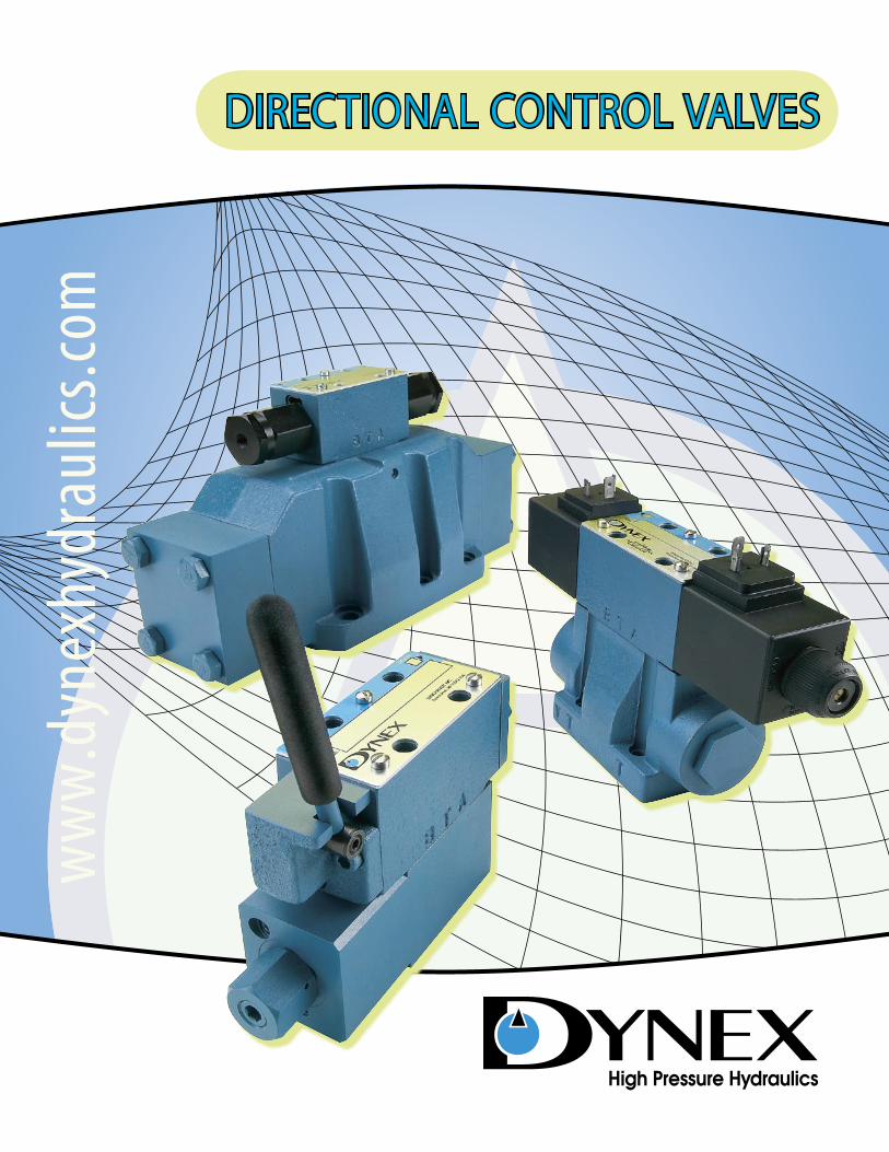
High-Pressure Spool Valves Control High-Torque WrenchesPortable hydraulic power packs use Dynex HP directional control valves at pressures to 10 000 psi (700 bar). A simple, sliding-spool design eliminates complex valve circuits for four-way control in high pressure circuits. A full range of actuators, spools and electrical options is available.
Aerospace Testing Requires High Pressure and Special FluidsDynex valves provide reliable shifting with extended life on R & D and production test stands. Pressure capability to 10 000 psi (700 bar) and compatibility with various water-based, phosphate ester and MIL-SPEC fluids makes these valves ideal for testing components used on commercial and military aircraft. Photo Copyright © Boeing
Valve Manifolds Facilitate Lighter, More Efficient Drill RigsRotary drill rigs use Dynex manifold-mounted valves to control the propel, feed-hoist and rotation circuits. The advanced hydraulic system improves operator control, eliminates high-pressure lines in the cab, and reduces connections for neater appearance, easier assembly and servicing. High-Pressure Operation on
Tunneling EquipmentDynex HP directional valves control cylinder movement on high-force pipe jacking equipment. The valves operate at pressures to 10 000 psi (700 bar), with reliable shifting in difficult, dirty conditions.
Valves for Improved Performance in Demanding Applications
DIRECTIONAL CONTROL VALVES
3
Table of Contents
Dynex Model – Mounting Pattern Page
Subplate Mounted Spool Valves
Internal Operators and Spool Descriptions . . . . . . . . . . . . . . . . . . . . . . . . . . . . . 4Application and Electrical Data . . . . . . . . . . . . . . . . . . . . . . . . . . . . . . . . . . . . . . . 6D03 – N .F .P .A . D03 (CETOP 3) . . . . . . . . . . . . . . . . . . . . . . . . . . . . . . . . . . . . . . . 9HP03 – High Pressure, Special Mounting Pattern . . . . . . . . . . . . . . . . . . . . . . . . 14D05 – N .F .P .A . D05 (CETOP 5) . . . . . . . . . . . . . . . . . . . . . . . . . . . . . . . . . . . . . . . 20HP05 – High Pressure, Special Mounting Pattern . . . . . . . . . . . . . . . . . . . . . . . . 25D05H – Modified N .F .P .A . D05 High Flow Pattern . . . . . . . . . . . . . . . . . . . . . . . . . 30D08 – N .F .P .A . D08 (CETOP 8) . . . . . . . . . . . . . . . . . . . . . . . . . . . . . . . . . . . . . . . 34D08H – Modified N .F .P .A . D08 High Flow Pattern . . . . . . . . . . . . . . . . . . . . . . . . . 39
Subplate Mounted Seated Valves
VST Series – HP03 Special Mounting Pattern . . . . . . . . . . . . . . . . . . . . . . . . . . . 43
High Pressure Sandwich Accessory Valves
VSW Series – HP03 and HP05 Special Mounting Pattern . . . . . . . . . . . . . . . . . . 48
USING THIS BROCHUREThis brochure contains specifications for Dynex directional control valves. Subplates and bolt kits are listed in the section for each specific valve model.
For subplate installation drawings, refer to separate Bulletin VES.SP.
Brochure NotesSpecifications shown were in effect when printed. Since errors or omissions are possible, contact your sales representative or the sales department for the most current specifications before ordering.
Dynex reserves the right to discontinue products or change designs at any time without incurring any obligation.
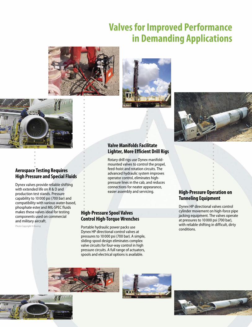
SMOOTH FLOW CONTROL AT PRESSURES TO 15 000 PSIDynex directional control valves provide a combination of high performance, efficiency and reliable operation .
N.F.P.A. (CETOP) Pattern ValvesSubplate mounted valves operate at pressures to 5000 psi (350 bar) . The valves provide low pressure drop, with large internal flow passages with uniform flow areas . High-force springs and solenoids, and tank return hydraulic boost passageways ensure reliable shifting . A four-land design provides smooth, balanced spool movement .
10 000 psi HP Series Spool Valves Simple sliding-spool valves eliminate complex valve circuits for four-way control in high pressure systems . A full range of actuators, spools and electrical options are available .
Seated Valves Operate to 15 000 psi VST valves provide high pressure venting or directional control . The ball-on-seat design eliminates silting for reliable shifting, even when unactuated for long periods at high pressure . Positive sealing makes them ideal for load holding functions .
Convenient Lever OperationFour handle positions on either end of valve allow convenient operator location . In-the-field changes are easy .
Explosion Proof OptionSolenoids with special enclosures are approved by UL and CSA for use in hazardous locations .
High-Pressure Sandwich ValvesVSW Series accessory valves simplify circuits and reduce installation costs . The valves mount under Dynex HP pattern control valves . This compact package reduces costs and assembly time with less piping and fittings .
LIGHTWEIGHT, DURABLE WIRING BOXEasy electrical connections with large wiring cavity
OPTIONAL ELECTRICAL CONNECTORSSimplifed wiring for error free installation and servicing
HIGH PRESSURE TUBESLong life with reliable shifting in high pressure “series” circuits
LOW HOLDING- CURRENT SOLENOIDSReduced energy use with low power requirement actuators
LARGE FLOW PASSAGES WITH UNIFORM FLOW AREASLow pressure-drop for reduced heat and increased efficiency
OPERATORS & SPOOLS
4
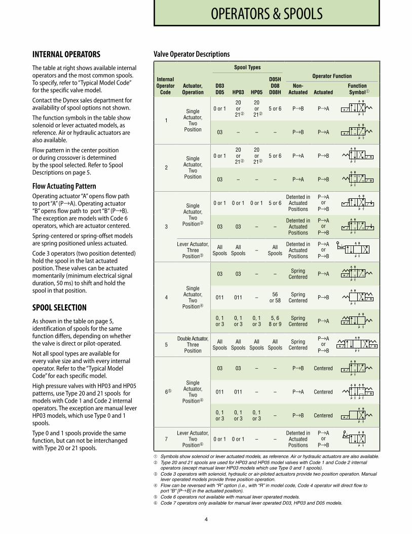
INTERNAL OPERATORSThe table at right shows available internal operators and the most common spools. To specify, refer to “Typical Model Code” for the specific valve model.
Contact the Dynex sales department for availability of spool options not shown.
The function symbols in the table show solenoid or lever actuated models, as reference. Air or hydraulic actuators are also available.
Flow pattern in the center position or during crossover is determined by the spool selected. Refer to Spool Descriptions on page 5.
Flow Actuating PatternOperating actuator “A” opens flow path to port “A” (P→A). Operating actuator “B” opens flow path to port “B” (P→B). The exception are models with Code 6 operators, which are actuator centered.
Spring-centered or spring-offset models are spring positioned unless actuated.
Code 3 operators (two position detented) hold the spool in the last actuated position. These valves can be actuated momentarily (minimum electrical signal duration, 50 ms) to shift and hold the spool in that position.
SPOOL SELECTIONAs shown in the table on page 5, identification of spools for the same function differs, depending on whether the valve is direct or pilot-operated.
Not all spool types are available for every valve size and with every internal operator. Refer to the “Typical Model Code” for each specific model.
High pressure valves with HP03 and HP05 patterns, use Type 20 and 21 spools for models with Code 1 and Code 2 internal operators. The exception are manual lever HP03 models, which use Type 0 and 1 spools.
Type 0 and 1 spools provide the same function, but can not be interchanged with Type 20 or 21 spools.
Valve Operator Descriptions
Internal Operator
Code
Spool Types
Actuator, Operation
D03 D05 HP03 HP05
D05H D08
D08H
Operator Function
Non- Actuated Actuated
Function Symbol
1
Single Actuator,
Two Position
0 or 120 or
21
20 or
215 or 6 P→B P→A
03 – – – P→B P→A
2
Single Actuator,
Two Position
0 or 120 or
21
20 or
215 or 6 P→A P→B
03 – – – P→A P→B
3
Single Actuator,
Two Position➂
0 or 1 0 or 1 0 or 1 5 or 6Detented in
Actuated Positions
P→A or
P→B
03 03 – –Detented in
Actuated Positions
P→A or
P→B
Lever Actuator, Three
Position➂
All Spools
All Spools – All
Spools
Detented in Actuated Positions
P→A or
P→B
4
Single Actuator,
Two Position➃
03 03 – – Spring Centered P→A
011 011 – 56 or 58
Spring Centered P→B
0, 1 or 3
0, 1 or 3
0, 1 or 3
5, 6 8 or 9
Spring Centered P→A
5Double Actuator,
Three Position
All Spools
All Spools
All Spools
All Spools
Spring Centered
P→A or
P→B
6➄
Single Actuator,
Two Position➃
03 03 – – P→B Centered
011 011 – – P→A Centered
0, 1 or 3
0, 1 or 3
0, 1 or 3 – P→B Centered
7Lever Actuator,
Two Position➅
0 or 1 0 or 1 – –Detented in
Actuated Positions
P→A or
P→B
Symbols show solenoid or lever actuated models, as reference. Air or hydraulic actuators are also available. Type 20 and 21 spools are used for HP03 and HP05 model valves with Code 1 and Code 2 internal
operators (except manual lever HP03 models which use Type 0 and 1 spools).➂ Code 3 operators with solenoid, hydraulic or air-piloted actuators provide two position operation. Manual
lever operated models provide three position operation.➃ Flow can be reversed with “R” option (i.e., with “R” in model code, Code 4 operator will direct flow to
port “B” [P→B] in the actuated position).➄ Code 6 operators not available with manual lever operated models.➅ Code 7 operators only available for manual lever operated D03, HP03 and D05 models.
A B
P T
A
A B
P T
B
A B
P T
A B
P T
A
A B
P T
A
A B
P T
A
A B
P T
B
B
A B
P T
B
A B
P T
A B
P T
A
A B
P T
B
A B
P T
A B
P T
A
A
P T
B
A
A
P T
B
A B
P T
OPERATORS & SPOOLS
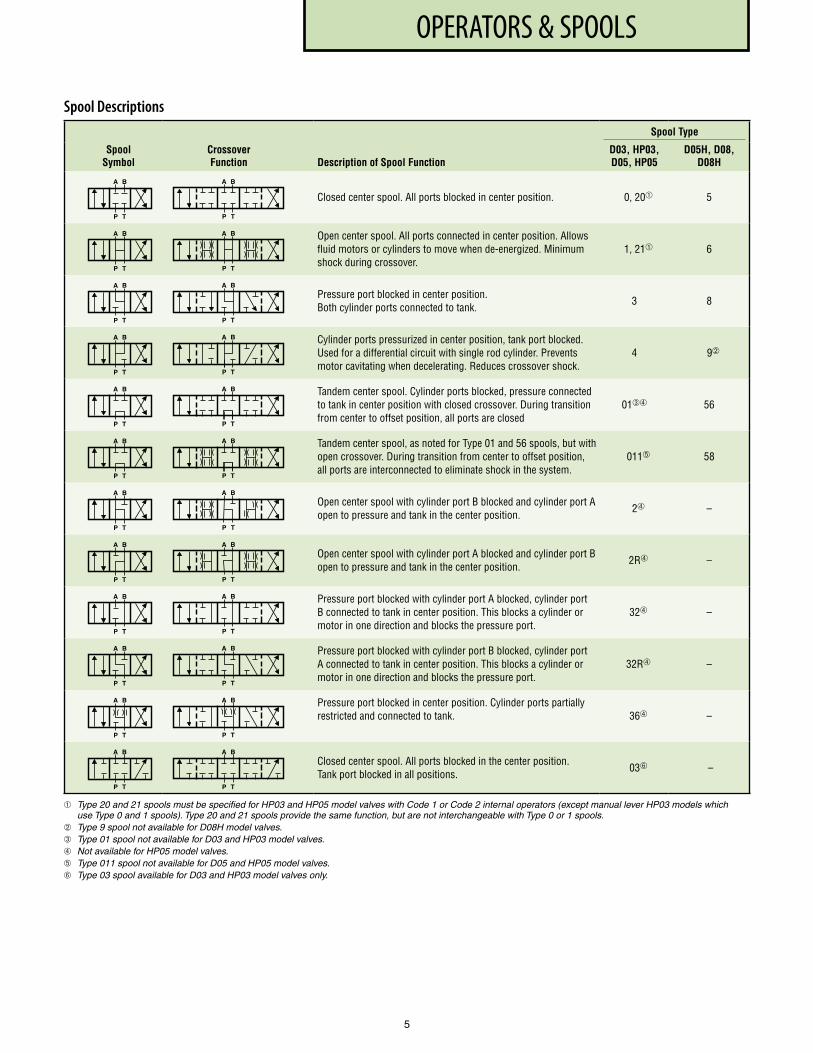
Spool Descriptions
Spool Symbol
Spool Type
Crossover Function Description of Spool Function
D03, HP03, D05, HP05
D05H, D08, D08H
Closed center spool . All ports blocked in center position . 0, 20 5
Open center spool . All ports connected in center position . Allows fluid motors or cylinders to move when de-energized . Minimum shock during crossover .
1, 21 6
Pressure port blocked in center position . Both cylinder ports connected to tank .
3 8
Cylinder ports pressurized in center position, tank port blocked . Used for a differential circuit with single rod cylinder . Prevents motor cavitating when decelerating . Reduces crossover shock .
4 9
Tandem center spool . Cylinder ports blocked, pressure connected to tank in center position with closed crossover . During transition from center to offset position, all ports are closed
01➂➃ 56
Tandem center spool, as noted for Type 01 and 56 spools, but with open crossover . During transition from center to offset position, all ports are interconnected to eliminate shock in the system .
011➄ 58
Open center spool with cylinder port B blocked and cylinder port A open to pressure and tank in the center position .
2➃ –
Open center spool with cylinder port A blocked and cylinder port B open to pressure and tank in the center position .
2R➃ –
Pressure port blocked with cylinder port A blocked, cylinder port B connected to tank in center position . This blocks a cylinder or motor in one direction and blocks the pressure port .
32➃ –
Pressure port blocked with cylinder port B blocked, cylinder port A connected to tank in center position . This blocks a cylinder or motor in one direction and blocks the pressure port .
32R➃ –
Pressure port blocked in center position . Cylinder ports partially restricted and connected to tank . 36➃ –
Closed center spool . All ports blocked in the center position . Tank port blocked in all positions .
03➅ –
Type 20 and 21 spools must be specified for HP03 and HP05 model valves with Code 1 or Code 2 internal operators (except manual lever HP03 models which use Type 0 and 1 spools). Type 20 and 21 spools provide the same function, but are not interchangeable with Type 0 or 1 spools.
Type 9 spool not available for D08H model valves.➂ Type 01 spool not available for D03 and HP03 model valves.➃ Not available for HP05 model valves.➄ Type 011 spool not available for D05 and HP05 model valves.➅ Type 03 spool available for D03 and HP03 model valves only.
A B
P T
A B
P T
A B
P T
A B
P T
A B
P T
A B
P T
A B
P T
A B
P T
A B
P T
A B
P T
A B
P T
A B
P T
A B
P T
A B
P T
A B
P T
A B
P T
A B
P T
A B
P T
A B
P T
A B
P T
A B
P T
A B
P T
A B
P T
A B
P T
5
APPLICATION
APPLICATION NOTES
Electrical DataThe tables list electrical specifications for Dynex directional valves.
D03 and HP03 valves use the same solenoids. High flow D05H, D08 and D08H valves also use this solenoid, with the D03 valve serving as a pilot valve.
D05, HP05 and VST valves use the same larger solenoid.
Mounting PositionUnrestricted for all valves.
Manual Operated ValvesLever operated models provide a choice of four positions on either port “A” end or port “B” end of valve.
To specify handle orientation, see “Typical Model Code” for the specific valve model.
Standard SealsAll valves use Fluorocarbon (Viton® or equivalent) o-rings, providing greater fluid compatibility and improved temperature range performance.
Fluid Recommendations50 to 1500 SUS (7 to 323 cSt) viscosity; -20° to 200° F (-29° to +93° C) temperature range.
Recommended FiltrationUse filtration to provide fluid which meets these ISO Code 4406 cleanliness values:
Standard N.F.P.A. (CETOP) Patterns, 18/16/13 to 5000 psi (350 bar);
HP03 and HP05 Patterns, 18/16/13 to 5000 psi (350 bar), 17/15/12 higher than 5000 psi (350 bar);
VST Series Seated Valves, 20/18/15.
Adequate filtration is critical for spool valves held in one position for long periods under pressure. Silting may cause spool valves to stick and not shift properly. Valves should also be cycled periodically.
Pressure Surges Consistent with standard practice, the system must be protected from pressure surges which can affect the shifting of any spool valve. In systems with multiple valves, a separate line to tank, or to another low pressure line, is recommended. This is especially critical with detented models.
Electrical Data – D03, HP03, D05H, D08 and D08H Valves
Solenoid Code
Input Voltage (Volts)
Frequency (Hz)
Inrush Current (Amps)
Holding Current (Amps)
Holding Power (Watts)
Coil Resistance
(Ohms + 10%)
24DF (Dual Frequency)
24 AC 50 9 .50 2 .60 27 1 .67
24 AC 60 8 .60 1 .75 22 1 .67
115DF (Dual Frequency)
110 AC 50 1 .65 0 .47 23 44 .2
115 AC 60 1 .55 0 .40 20 .5 44 .2
230DF (Dual Frequency)
220 AC 50 0 .86 0 .22 23 150
230 AC 60 0 .80 0 .18 20 .5 150
460DF (Dual Frequency)
440 AC 50 0 .41 0 .13 23 600
460 AC 60 0 .40 0 .10 21 600
12DC 12 DC – – – 28 5 .10
24DC 24 DC – – – 28 20 .60
12EP 12 DC – – – 33 4 .36
24EP 24 DC – – – 33 17 .50
110EP 110 AC 50 1 .86 0 .54 23 35 .20
115EP 115 AC 60 1 .90 0 .50 23 33 .50
Ordering codes listed are for standard wire leads. Plug-in Terminal solenoids (“Hirschmann” type) are also avaialble. See “Typical Model Code” for the specific valve model.
Electrical Data – D05, HP05 and VST Valves
Solenoid Code
Input Voltage (Volts)
Frequency (Hz)
Inrush Current (Amps)
Holding Current (Amps)
Holding Power (Watts)
Coil Resistance
(Ohms + 10%)
24DF (Dual Frequency)
24 AC 50 23 .00 4 .10 38 0 .56
24 AC 60 21 .00 3 .15 38 0 .56
115DF (Dual Frequency)
110 AC 50 4 .80 0 .88 37 10 .20
115 AC 60 4 .30 0 .72 35 10 .20
230DF (Dual Frequency)
220 AC 50 2 .40 0 .44 37 40 .80
230 AC 60 2 .20 0 .36 35 40 .80
460DF (Dual Frequency)
440 AC 50 1 .30 0 .23 37 188 .50
460 AC 60 1 .20 0 .20 35 188 .50
12DC 12 DC – – – 48 3 .00
24DC 24 DC – – – 48 12 .00
250DC 250 DC – – – 48 1300 .00
12EP 12 DC – – – 48 3 .00
24EP 24 DC – – – 48 12 .00
110EP 110 AC 50 4 .20 1 .00 43 10 .72
115EP 115 AC 60 3 .90 8 .90 43 10 .47
220EP 220 AC 50 2 .09 0 .50 43 43 .35
Ordering codes listed are for standard wire leads. Plug-in Terminal solenoids (“Hirschmann” type) are also avaialble. See “Typical Model Code” for the specific valve model.
Drain and Pilot ConnectionsOn pilot operated models, valves are supplied with external drain and internal pilot as standard.
Internal drain and external pilot are optional. See “Typical Model Code”
for each valve model. Also refer to the installation drawings, which indicate plug locations for various drain and pilot configurations.
External drain is recommended for applications with high tank pressure, to assure proper spool shifting.
6
7
ELECTRICAL OPTIONS
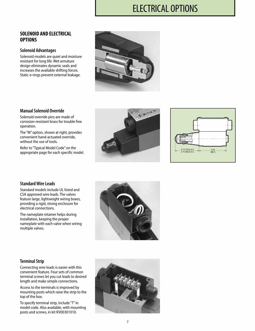
SOLENOID AND ELECTRICAL OPTIONS
Solenoid AdvantagesSolenoid models are quiet and moisture resistant for long life. Wet armature design eliminates dynamic seals and increases the available shifting forces. Static o-rings prevent external leakage.
Manual Solenoid OverrideSolenoid override pins are made of corrosion-resistant brass for trouble free operation.
The “M” option, shown at right, provides convenient hand-actuated override, without the use of tools.
Refer to “Typical Model Code” on the appropriate page for each specific model.
Terminal Strip Connecting wire leads is easier with this convenient feature. Four sets of common terminal screws let you cut leads to desired length and make simple connections.
Access to the terminals is improved by mounting posts which raise the strip to the top of the box.
To specify terminal strip, include “T” in model code. Also available, with mounting posts and screws, in kit KV00301010.
Standard Wire LeadsStandard models include UL listed and CSA approved wire leads. The valves feature large, lightweight wiring boxes, providing a rigid, strong enclosure for electrical connections.
The nameplate retainer helps during installation, keeping the proper nameplate with each valve when wiring multiple valves.
3 .13 (79,5) A .C .3 .74 (95,0) D .C .
3 .53(89,7)
8
ELECTRICAL OPTIONS
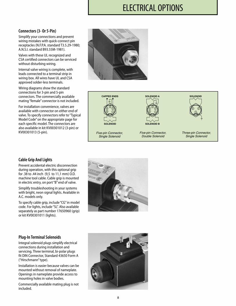
Connectors (3- Or 5-Pin)Simplify your connections and prevent wiring mistakes with quick-connect pin receptacles (N.F.P.A. standard T3.5.29-1980; A.N.S.I. standard B93.55M-1981).
Valves with these UL recognized and CSA certified connectors can be serviced without disturbing wiring.
Internal valve wiring is complete, with leads connected to a terminal strip in wiring box. All wires have UL and CSA approved solder-less terminals.
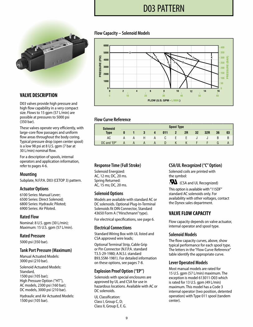
Wiring diagrams show the standard connections for 3-pin and 5-pin connectors. The commercially available mating “female” connector is not included.
For installation convenience, valves are available with connector on either end of valve. To specify connectors refer to “Typical Model Code” on the appropriate page for each specific model. The connectors are also available in kit KV00301012 (3-pin) or KV00301013 (5-pin).
1
43
2
5
CAPPED ENDS
SOLENOID
1
3
5
SOLENOID A
SOLENOID B
4 2
SOLENOID
3 2
1
Five-pin Connector, Single Solenoid
Five-pin Connector, Double Solenoid
Three-pin Connector, Single Solenoid
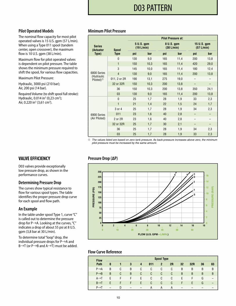
Cable Grip And LightsPrevent accidental electric discon nection during operation, with this optional grip for .38 to .44 inch (9,5 to 11,1 mm) O.D. machine tool cable. Cable grip is mounted in electric entry, on port “B” end of valve.
Simplify troubleshooting in your systems with bright, neon signal lights. Available in A.C. models only.
To specify cable grip, include “CG” in model code. For lights, include “SL”. Also available separately as part number 17650960 (grip) or kit KV00301011 (lights).
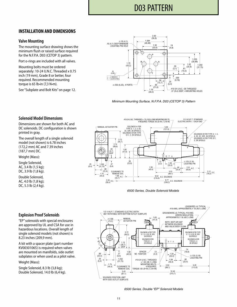
Plug-In Terminal SolenoidsIntegral solenoid plugs simplify electrical connections during installation and servicing. Three terminal, bi-polar plugs fit DIN Connector, Standard 43650 Form A (“Hirsch mann” type).
Installation is easier because valves can be mounted without removal of nameplate. Openings in nameplate provide access to mounting holes in valve bodies.
Commercially available mating plug is not included.
PF3000 SERIES, 10 DESIGND03 PATTERN
VALVE DESCRIPTIOND03 valves provide high pressure and high flow capability in a very compact size. Flows to 15 gpm (57 L/min) are possible at pressures to 5000 psi (350 bar).
These valves operate very efficiently, with large-core flow passages and uniform flow areas throughout the body coring. Typical pressure drop (open center spool) is a low 98 psi at 8 U.S. gpm (7 bar at 30 L/min) nominal flow.
For a description of spools, internal operators and application information, refer to pages 4-6.
MountingSubplate, N.F.P.A. D03 (CETOP 3) pattern.
Actuator Options6100 Series: Manual Lever; 6500 Series: Direct Solenoid; 6800 Series: Hydraulic Piloted; 6900 Series: Air Piloted.
Rated FlowNominal: 8 U.S. gpm (30 L/min); Maximum: 15 U.S. gpm (57 L/min).
Rated Pressure5000 psi (350 bar).
Tank Port Pressure (Maximum)Manual Actuated Models: 3000 psi (210 bar).
Solenoid Actuated Models: Standard, 1500 psi (105 bar); High Pressure Option (“HT”), AC models, 2300 psi (160 bar); DC models, 3000 psi (210 bar).
Hydraulic and Air Actuated Models: 1500 psi (105 bar).
Response Time (Full Stroke)Solenoid Energized: AC, 12 ms; DC, 20 ms. Spring Returned: AC, 15 ms; DC, 20 ms.
Solenoid OptionsModels are available with standard AC or DC solenoids. Optional Plug-In-Terminal Solenoids fit DIN Connector, Standard 43650 Form A (“Hirschmann” type).
For electrical specifications, see page 6.
Electrical ConnectionsStandard Wiring Box with UL listed and CSA approved wire leads;
Optional Terminal Strip, Cable Grip or Pin Connector (N.F.P.A. standard T3.5-29-1980; A.N.S.I. standard B93.55M-1981). For detailed information on these options, see pages 7-8.
Explosion Proof Option (“EP”)Solenoids with special enclosures are approved by UL and CSA for use in hazardous locations. Available with AC or DC solenoids.
UL Classification: Class I, Group C, D; Class II, Group E, F, G.
CSA/UL Recognized (“C” Option)Solenoid coils are printed with the symbol:
®C (CSA and UL Recognized)
This option is available with “115DF” standard AC solenoids only. For availability with other voltages, contact the Dynex sales department.
VALVE FLOW CAPACITYFlow capacity depends on valve actuator, internal operator and spool type.
Solenoid ModelsThe flow capacity curves, above, show typical performance for each spool type. The letters in the “Flow Curve Reference” table identify the appropriate curve.
Lever Operated ModelsMost manual models are rated for 15 U.S. gpm (57 L/min) maximum. The exception is model 613011-D03 which is rated for 13 U.S. gpm (49 L/min) maximum. This model has a Code 3 internal operator (two position, detented operation) with Type 011 spool (tandem center).
9
Flow Capacity – Solenoid Models
PR
ES
SU
RE
(P
SI)
FLOW (U.S. GPM - L/MIN.)
PR
ES
SU
RE
(B
AR
)
400
350
300
250
200
150
100
50
00 2 4 6 8 10 12 14 16
0
1000
2000
3000
4000
5000
6000
0 10 20 30 40 50 60
A
B C
F GD E
H J K
Flow Curve Reference
Solenoid Type
Spool Type
0 1 3 4 011 2 2R 32 32R 36 03
AC A A H A C E E J J B B DC and "EP" A A A A D K K F F G A
PF3000 SERIES, 10 DESIGND03 PATTERN
Minimum Pilot Pressure
Series (Actuator
Type)Spool Type
Pilot Pressure at:
5 U.S. gpm (19 L/min)
8 U.S. gpm (30 L/min)
15 U.S. gpm (57 L/min)
psi bar psi bar psi bar
6800 Series(Hydraulic Piloted)
0 130 9,0 165 11,4 200 13,8
1 150 10,3 165 11,4 420 29,0
3 145 10,0 165 11,4 180 12,4
4 130 9,0 165 11,4 200 13,8
011, 2 or 2R 190 13,1 275 19,0 – –
32 or 32R 150 10,3 200 13,8 – –
36 150 10,3 200 13,8 350 24,1
03 130 9,0 165 11,4 200 13,8
6900 Series (Air Piloted)
0 25 1,7 28 1,9 33 2,3
1 21 1,4 22 1,5 24 1,7
3 or 4 25 1,7 28 1,9 34 2,3
011 23 1,6 40 2,8 – –
2 or 2R 23 1,6 40 2,8 – –
32 or 32R 25 1,7 30 2,1 – –
36 25 1,7 28 1,9 34 2,3
03 25 1,7 28 1,9 33 2,3
The values listed are based on zero tank pressure. As back-pressure increases above zero, the minimum pilot pressure must be increased by the same amount.
Flow Curve Reference
Flow Path
Spool Type
0 1 3 4 011 2 2R 32 32R 36 03
P→A B C B C C C C B B B B P→B B C B C C C C B B B B A→T E F F E C C C E F G – B→T E F F E C C C F E G – P→T – D – – A A A – – – –
Pilot Operated ModelsThe nominal flow capacity for most pilot operated valves is 15 U.S. gpm (57 L/min). When using a Type 011 spool (tandem center, open cross over), the maximum flow is 10 U.S. gpm (38 L/min).
Maximum flow for pilot operated valves is dependent on pilot pressure. The table shows the minimum pressure required to shift the spool, for various flow capacities.
Maximum Pilot Pressure:
Hydraulic, 3000 psi (210 bar); Air, 200 psi (14 bar).
Required Volume (to shift spool full stroke): Hydraulic, 0.014 in3 (0,23 cm3); Air, 0.220 in3 (3,61 cm3).
VALVE EFFICIENCYD03 valves provide exceptionally low pressure drop, as shown in the performance curves.
Determining Pressure DropThe curves show typical resistance to flow for various spool types. The table identifies the proper pressure drop curve for each spool and flow path.
An ExampleIn the table under spool Type 1, curve “C” is called out to determine the pressure drop for P→A. Looking at the curves, “C” indicates a drop of about 55 psi at 8 U.S. gpm (3,8 bar at 30 L/min).
To determine total “loop” drop, the individual pressure drops for P→A and B→T (or P→B and A→T) must be added.
Pressure Drop (∆P)
10
PF3000 SERIES, 10 DESIGND03 PATTERN
P
AB
T
∅.16 (4,1),.16 (4,1) DEEP MINIMUM
LOCATING PIN HOLE
1.70(43,2)
∅.250 (6,35), 4 PORTS
1.30(33,0)
1.594(40,49)
2.00(50,8)
.19(4,8)
.25(6,4)
.030(0,76)
.20(5,1) .61
(15,5)
1.02(25,9)
1.220(30,99)
1.250(31,75)
.50(12,7)
.85(21,6)
1.19(30,2)
#10-24 U.N.C.–2B THREADED.37 (9,4) DEEP, 4 MOUNTING HOLES
.0004/4.0(0,010/102)
32(0,80)
Minimum Mounting Surface, N.F.P.A. D03 (CETOP 3) Pattern
.92 (23,4)
3.53 (89,7)
.13 (3,3)
1.59 (40,4)
1.30 (33,0)
3.12 (79,2) D.C.
2.51 (63,8)
A.C.
∅.125 (3,18) LOCATING PIN
9.77 (248,2)
D.C. SOLENOID
8.54 (216,9)
A.C. SOLENOID
.94 (23,9)
1.88 (47,8)
SOLENOID A FOR TYPE 0, 1, 3, 4, 03 ,
32, 32R, 36 SPOOLS; SOLENOID B FOR TYPE
011, 2, 2R SPOOLS SOLENOID B FOR TYPE 0, 1, 3, 4, 03, 32, 32R, 36 SPOOLS; SOLENOID A FOR TYPE 011, 2, 2R SPOOLS
5.00 (127,0)
1/2- 14 N.P.T. STANDARD ELECTRIC ENTRY, 1 EACH END
2.30 (58,4)
D.C.
CLEARANCE TO REMOVE COIL
.38 (9,7) GRIP
2.74 (69,6)
3.73 (94,7)
MANUAL ACTUATOR PI N
1.68 (42,7)
A.C.
#10-24 U.N.C. THREADED x .75 (19,0) LONG MOUNTING BOLTS, 4 REQUIRED; TORQUE: 65 LB • IN ( 7,3 N • M)
.37 (9,4)
.88 (22,4)
1.75 (44,4)
1.250 (31,75)
.25 (6,4)
6500 Series, Double Solenoid Models
6500 Series, Double “EP” Solenoid Models
SPACE R NO. 10591320
SOLENOID A FOR TYPE 0, 1, 3, 4, 03, 32, 32R,
36 SPOOLS
.92 (23,4)
3.53 (89,7)
.13 (3,3)
1.59 (40,4)
1.30 (33,0) ∅.125 (3,18)
LOCATING PIN
1.75 (44,4)
.88 (22,4)
1.13 (28,7) GRIP
#10-24 U.N.C. THREADEDx 1.50 (38,1) LONGMOUNTING BOLTS,
4 REQUIRED, TORQUE: 65 LB • IN (7,3 N • M)
1.69 (42,9)
.74 (18,8)
4.45 (113,0)
12.43 (315,7)
3.43 (87,1)
CLEARANCE TO REMOVE COIL
SOLENOID POSITION LIMIT WITH SIDE OUTLET SUBPLATE
MANUAL ACTUATOR PI N
3.72 (94,5)
∅ 2.88 (73.2)
1/2-14 N.P.T. STANDARD ELECTRIC ENTRY, 360 ̊ ROTATABLE WITH BOTTOM OUTLET SUBPLATE
NOTE: KEEP AIR GAP BETWEEN SOLENOI D AND VALVE BODY CLEAN
GROUNDWIRE (2) TYPICAL #18 AWG (GREEN INSULATION)
APPROXIMATELY 18 (457) LONG
LEADWIRES (4) TYPICAL #18 AWG, APPROXIMATELY 18 (457) LONG
1.63 (41,4)
45 ̊
SOLENOID B FOR TYPE 0, 1, 3, 4, 03, 32, 32R
36 SPOOLS
SOLENOID A FO R TYPE 011, 2, 2R SPOOLS
SOLENOID B FO R TYPE 011, 2, 2R SPOOLS
.37 (9,4)
1.250 (31,75)
.25 (6,4)
11
INSTALLATION AND DIMENSIONS
Valve MountingThe mounting surface drawing shows the minimum flush or raised surface required for the N.F.P.A. D03 (CETOP 3) pattern.
Port o-rings are included with all valves.
Mounting bolts must be ordered separately: 10-24 U.N.C. Threaded x 0.75 inch (19 mm), Grade 8 or better, four required. Recommended mounting torque is 65 lb•in (7,3 N•m).
See “Subplate and Bolt Kits” on page 12.
Solenoid Model DimensionsDimensions are shown for both AC and DC solenoids. DC configuration is shown printed in gray.
The overall length of a single solenoid model (not shown) is 6.78 inches (172,2 mm) AC and 7.39 inches (187,7 mm) DC.
Weight (Mass):
Single Solenoid, AC, 3.4 lb (1,5 kg); DC, 3.9 lb (1,8 kg).
Double Solenoid, AC, 4.0 lb (1,8 kg); DC, 5.3 lb (2,4 kg).
Explosion Proof Solenoids“EP” solenoids with special enclosures are approved by UL and CSA for use in hazardous locations. Overall length of single solenoid models (not shown) is 8.23 inches (209,9 mm).
A kit with a spacer plate (part number KV00301065) is required when valves are mounted on manifolds, side outlet subplates or when used as a pilot valve.
Weight (Mass):
Single Solenoid, 8.3 lb (3,8 kg); Double Solenoid, 14.0 lb (6,4 kg).
PF3000 SERIES, 10 DESIGND03 PATTERN
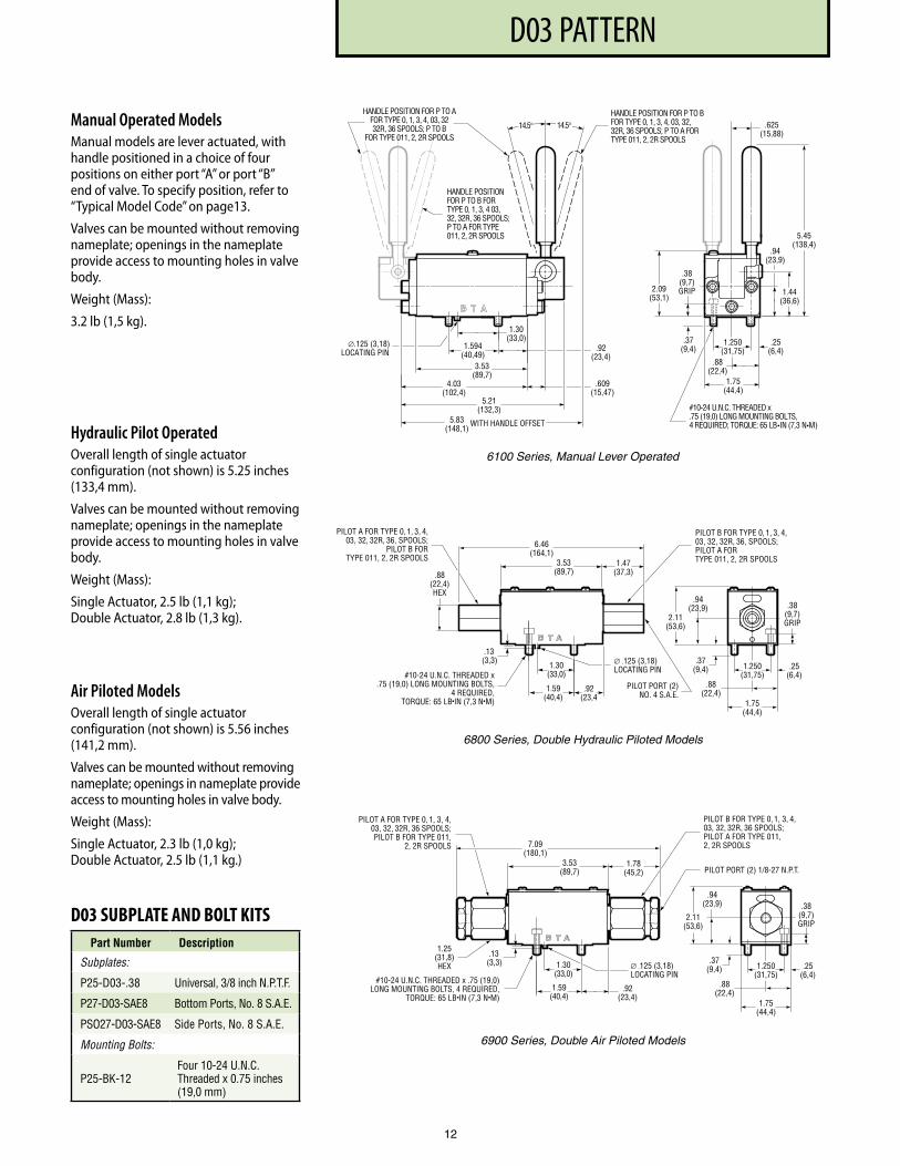
Manual Operated ModelsManual models are lever actuated, with handle positioned in a choice of four positions on either port “A” or port “B” end of valve. To specify position, refer to “Typical Model Code” on page13.
Valves can be mounted without removing nameplate; openings in the name plate provide access to mounting holes in valve body.
Weight (Mass):
3.2 lb (1,5 kg).
Hydraulic Pilot OperatedOverall length of single actuator configuration (not shown) is 5.25 inches (133,4 mm).
Valves can be mounted without removing nameplate; openings in the name plate provide access to mounting holes in valve body.
Weight (Mass):
Single Actuator, 2.5 lb (1,1 kg); Double Actuator, 2.8 lb (1,3 kg).
Air Piloted ModelsOverall length of single actuator configuration (not shown) is 5.56 inches (141,2 mm).
Valves can be mounted without removing nameplate; openings in name plate provide access to mounting holes in valve body.
Weight (Mass):
Single Actuator, 2.3 lb (1,0 kg); Double Actuator, 2.5 lb (1,1 kg.)
#10-24 U.N.C. THREADED x . 75 (19,0) LONG MOUNTING BOLTS , 4 REQUIRED; TORQUE: 65 LB•IN (7,3 N•M)
HANDLE POSITION FOR P TO B FOR TYPE 0, 1, 3, 4, 03, 32, 32R, 36 SPOOLS; P TO A FOR TYPE 011, 2, 2R SPOOLS
1.594 (40,49)
.92 (23,4)
.625 (15,88)
.37 (9,4)
.88 (22,4)
1.75 (44,4)
1.250 (31,75)
.25 (6,4)
HANDLE POSITION FOR P TO A FOR TYPE 0, 1, 3, 4, 03, 32 32R, 36 SPOOLS; P TO B
FOR TYPE 011, 2, 2R SPOOLS
.38 (9,7 ) GRIP 2.09
(53,1)
.94 (23,9)
1.44 (36,6)
5.45 (138,4)
14.5 ° 14.5 °
HANDLE POSITION FOR P TO B FOR TYPE 0, 1, 3, 4 03, 32, 32R, 36 SPOOLS; P TO A FOR TYPE 011, 2, 2R SPOOLS
1.30 (33,0)
.609 (15,47)
3.53 (89,7)
4.03 (102,4)
5.21 (132,3)
5.83 (148,1)
∅.125 (3,18) LOCATING PIN
WITH HANDLE OFFSET
6100 Series, Manual Lever Operated
PILOT PORT (2)NO. 4 S.A.E.
6.46(164,1)
1.47(37,3).88
(22,4)HEX
1.75(44,4)
.88(22,4)
2.11(53,6)
.94(23,9)
.37(9,4)
.92(23,4
.13(3,3) ∅ .125 (3,18)
LOCATING PIN
1.59(40,4)
1.30(33,0)
.38(9,7)GRIP
#10-24 U.N.C. THREADED x.75 (19,0) LONG MOUNTING BOLTS,
4 REQUIRED,TORQUE: 65 LB•IN (7,3 N•M)
PILOT A FOR TYPE 0, 1, 3, 4,03, 32, 32R, 36, SPOOLS;
PILOT B FORTYPE 011, 2, 2R SPOOLS
PILOT B FOR TYPE 0, 1, 3, 4,03, 32, 32R, 36, SPOOLS;PILOT A FORTYPE 011, 2, 2R SPOOLS3.53
(89,7)
1.250(31,75)
.25(6,4)
6800 Series, Double Hydraulic Piloted Models
PILOT PORT (2) 1/8-27 N.P.T.
.92(23,4)
.13(3,3) ∅ .125 (3,18)
LOCATING PIN
1.59(40,4)
1.25(31,8)HEX
7.09(180,1)
1.78(45,2)
2.11(53,6)
.94(23,9) .38
(9,7)GRIP
#10-24 U.N.C. THREADED x .75 (19,0)LONG MOUNTING BOLTS, 4 REQUIRED,
TORQUE: 65 LB•IN (7,3 N•M)
PILOT A FOR TYPE 0, 1, 3, 4,03, 32, 32R, 36 SPOOLS;PILOT B FOR TYPE 011,
2, 2R SPOOLS
PILOT B FOR TYPE 0, 1, 3, 4,03, 32, 32R, 36 SPOOLS;PILOT A FOR TYPE 011,2, 2R SPOOLS
3.53(89,7)
1.30(33,0)
1.75(44,4)
.88(22,4)
.37(9,4) 1.250
(31,75).25
(6,4)
6900 Series, Double Air Piloted Models
12
D03 SUBPLATE AND BOLT KITSPart Number Description
Subplates:
P25-D03- .38 Universal, 3/8 inch N .P .T .F .
P27-D03-SAE8 Bottom Ports, No . 8 S .A .E .
PSO27-D03-SAE8 Side Ports, No . 8 S .A .E .
Mounting Bolts:
P25-BK-12Four 10-24 U .N .C . Threaded x 0 .75 inches (19,0 mm)
PF3000 SERIES, 10 DESIGND03 PATTERN
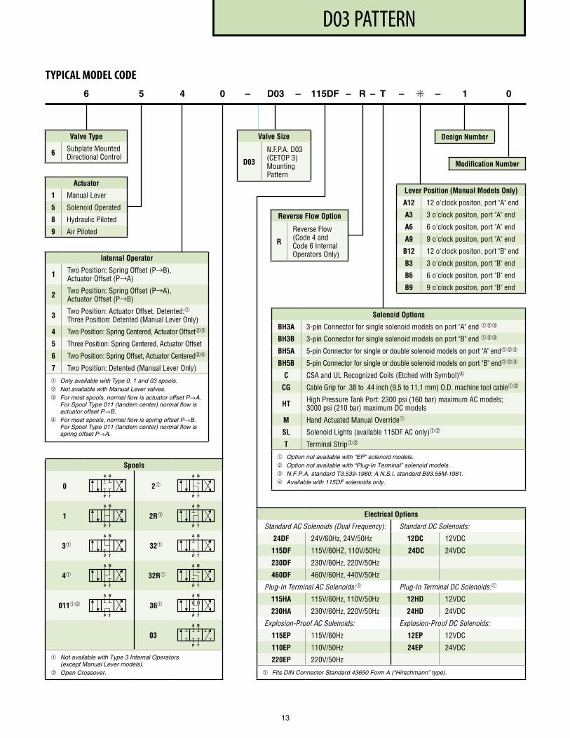
Actuator
1 Manual Lever
5 Solenoid Operated
8 Hydraulic Piloted
9 Air Piloted
6 5 4 0 – D03 – 115DF – R – T – ✳ – 1 0
Valve Type
6 Subplate Mounted Directional Control
Lever Position (Manual Models Only)
A12 12 o'clock positon, port "A" end
A3 3 o'clock positon, port "A" end
A6 6 o'clock positon, port "A" end
A9 9 o'clock positon, port "A" end
B12 12 o'clock positon, port "B" end
B3 3 o'clock positon, port "B" end
B6 6 o'clock positon, port "B" end
B9 9 o'clock positon, port "B" end
Design Number
Modification Number
TYPICAL MODEL CODE
Spools
0 2
1 2R
3 32
4 32R
011 36
03
Not available with Type 3 Internal Operators (except Manual Lever models).
Open Crossover.
Electrical Options
Standard AC Solenoids (Dual Frequency): Standard DC Solenoids:
24DF 24V/60Hz, 24V/50Hz 12DC 12VDC
115DF 115V/60HZ, 110V/50Hz 24DC 24VDC
230DF 230V/60Hz, 220V/50Hz
460DF 460V/60Hz, 440V/50Hz
Plug-In Terminal AC Solenoids: Plug-In Terminal DC Solenoids:
115HA 115V/60Hz, 110V/50Hz 12HD 12VDC
230HA 230V/60Hz, 220V/50Hz 24HD 24VDC
Explosion-Proof AC Solenoids: Explosion-Proof DC Solenoids:
115EP 115V/60Hz 12EP 12VDC
110EP 110V/50Hz 24EP 24VDC
220EP 220V/50Hz
Fits DIN Connector Standard 43650 Form A (“Hirschmann” type).
Reverse Flow Option
R
Reverse Flow (Code 4 and Code 6 Internal Operators Only)
A B
P T
A B
P T
A B
P T
A B
P T
A B
P T
A B
P T
A B
P T
A B
P T
A B
P T
A B
P T
A B
P T
Valve Size
D03
N .F .P .A . D03 (CETOP 3) Mounting Pattern
13
Internal Operator
1 Two Position: Spring Offset (P→B), Actuator Offset (P→A)
2 Two Position: Spring Offset (P→A), Actuator Offset (P→B)
3 Two Position: Actuator Offset, Detented;Three Position: Detented (Manual Lever Only)
4 Two Position: Spring Centered, Actuator Offset➂
5 Three Position: Spring Centered, Actuator Offset
6 Two Position: Spring Offset, Actuator Centered➃
7 Two Position: Detented (Manual Lever Only)
Only available with Type 0, 1 and 03 spools. Not available with Manual Lever valves.➂ For most spools, normal flow is actuator offset P→A.
For Spool Type 011 (tandem center) normal flow is actuator offset P→B.
➃ For most spools, normal flow is spring offset P→B. For Spool Type 011 (tandem center) normal flow is spring offset P→A.
Solenoid Options
BH3A 3-pin Connector for single solenoid models on port "A" end ➂
BH3B 3-pin Connector for single solenoid models on port "B" end ➂
BH5A 5-pin Connector for single or double solenoid models on port "A" end➂
BH5B 5-pin Connector for single or double solenoid models on port "B" end➂
C CSA and UL Recognized Coils (Etched with Symbol)➃
CG Cable Grip for .38 to .44 inch (9,5 to 11,1 mm) O .D . machine tool cable
HT High Pressure Tank Port: 2300 psi (160 bar) maximum AC models; 3000 psi (210 bar) maximum DC models
M Hand Actuated Manual Override
SL Solenoid Lights (available 115DF AC only)
T Terminal Strip
Option not available with “EP” solenoid models. Option not available with “Plug-In Terminal” solenoid models. ➂ N.F.P.A. standard T3.539-1980; A.N.S.I. standard B93.55M-1981. ➃ Available with 115DF solenoids only.
PF3000 SERIES, 10 DESIGNHIGH PRESSURE HP03 PATTERN
14
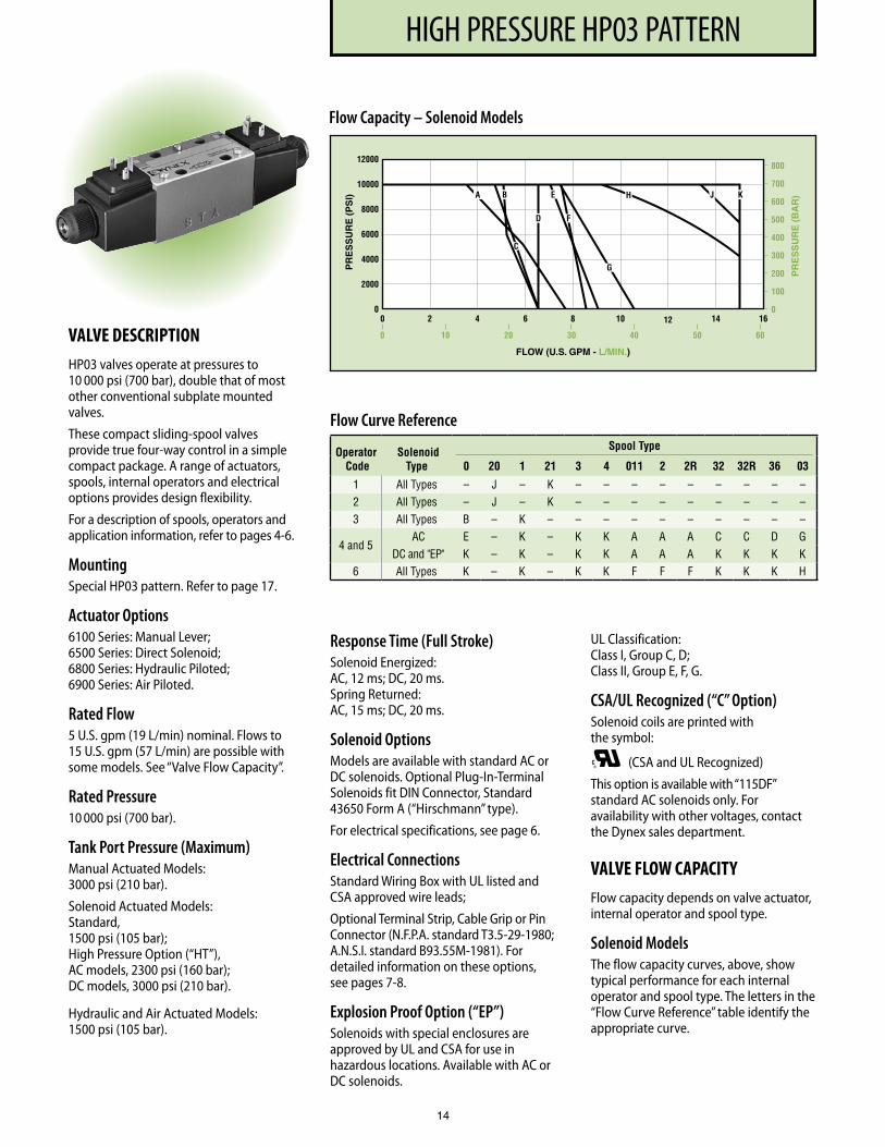
Flow Capacity – Solenoid Models
VALVE DESCRIPTIONHP03 valves operate at pressures to 10 000 psi (700 bar), double that of most other conventional subplate mounted valves.
These compact sliding-spool valves provide true four-way control in a simple compact package. A range of actuators, spools, internal operators and electrical options provides design flexibility.
For a description of spools, operators and application information, refer to pages 4-6.
MountingSpecial HP03 pattern. Refer to page 17.
Actuator Options6100 Series: Manual Lever; 6500 Series: Direct Solenoid; 6800 Series: Hydraulic Piloted; 6900 Series: Air Piloted.
Rated Flow5 U.S. gpm (19 L/min) nominal. Flows to 15 U.S. gpm (57 L/min) are possible with some models. See “Valve Flow Capacity”.
Rated Pressure10 000 psi (700 bar).
Tank Port Pressure (Maximum)Manual Actuated Models: 3000 psi (210 bar).
Solenoid Actuated Models: Standard, 1500 psi (105 bar); High Pressure Option (“HT”), AC models, 2300 psi (160 bar); DC models, 3000 psi (210 bar).
Hydraulic and Air Actuated Models: 1500 psi (105 bar).
Flow Curve Reference
Operator Code
Solenoid Type
Spool Type
0 20 1 21 3 4 011 2 2R 32 32R 36 03
1 All Types – J – K – – – – – – – – –2 All Types – J – K – – – – – – – – –3 All Types B – K – – – – – – – – – –
4 and 5AC E – K – K K A A A C C D G
DC and "EP" K – K – K K A A A K K K K6 All Types K – K – K K F F F K K K H
Response Time (Full Stroke)Solenoid Energized: AC, 12 ms; DC, 20 ms. Spring Returned: AC, 15 ms; DC, 20 ms.
Solenoid OptionsModels are available with standard AC or DC solenoids. Optional Plug-In-Terminal Solenoids fit DIN Connector, Standard 43650 Form A (“Hirschmann” type).
For electrical specifications, see page 6.
Electrical ConnectionsStandard Wiring Box with UL listed and CSA approved wire leads;
Optional Terminal Strip, Cable Grip or Pin Connector (N.F.P.A. standard T3.5-29-1980; A.N.S.I. standard B93.55M-1981). For detailed information on these options, see pages 7-8.
Explosion Proof Option (“EP”)Solenoids with special enclosures are approved by UL and CSA for use in hazardous locations. Available with AC or DC solenoids.
UL Classification: Class I, Group C, D; Class II, Group E, F, G.
CSA/UL Recognized (“C” Option)Solenoid coils are printed with the symbol:
®C (CSA and UL Recognized)
This option is available with “115DF” standard AC solenoids only. For availability with other voltages, contact the Dynex sales department.
VALVE FLOW CAPACITYFlow capacity depends on valve actuator, internal operator and spool type.
Solenoid ModelsThe flow capacity curves, above, show typical performance for each internal operator and spool type. The letters in the “Flow Curve Reference” table identify the appropriate curve.
PF3000 SERIES, 10 DESIGNHIGH PRESSURE HP03 PATTERN
15
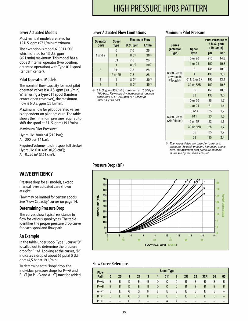
Lever Actuated ModelsMost manual models are rated for 15 U.S. gpm (57 L/min) maximum.
The exception is model 613011-D03 which is rated for 13 U.S. gpm (49 L/min) maximum. This model has a Code 3 internal operator (two position, detented operation) with Type 011 spool (tandem center).
Pilot Operated ModelsThe nominal flow capacity for most pilot operated valves is 8 U.S. gpm (30 L/min). When using a Type 011 spool (tandem center, open cross over), the maximum flow is 6 U.S. gpm (23 L/min).
Maximum flow for pilot operated valves is dependent on pilot pressure. The table shows the minimum pressure required to shift the spool at 5 U.S. gpm (19 L/min).
Maximum Pilot Pressure:
Hydraulic, 3000 psi (210 bar); Air, 200 psi (14 bar).
Required Volume (to shift spool full stroke): Hydraulic, 0.014 in3 (0,23 cm3); Air, 0.220 in3 (3,61 cm3).
Lever Actuated Flow Limitations
Operator Code
Spool Type
Maximum Flow
U.S. gpm L/min
1 and 20 7 .0 261 8 .0 30
03 7 .0 26
31 8 .0 30
011 7 .5 282 or 2R 7 .5 28
5 1 8 .0 30
7 1 8 .0 30
8 U.S. gpm (30 L/min) maximum at 10 000 psi (700 bar). Flow capacity increases at reduced pressure; i.e. 11 U.S. gpm (41 L/min) at 2000 psi (140 bar).
Minimum Pilot Pressure
Series (Actuator
Type)Spool Type
Pilot Pressure at 5 U.S. gpm (19 L/min)
psi bar
6800 Series(Hydraulic Piloted)
0 or 20 215 14,8
1 or 21 150 10,3
3 145 10,0
4 130 9,0
011, 2 or 2R 190 13,1
32 or 32R 150 10,3
36 150 10,3
03 130 9,0
6900 Series (Air Piloted)
0 or 20 25 1,7
1 or 21 21 1,4
3 or 4 25 1,7
011 23 1,6
2 or 2R 23 1,6
32 or 32R 25 1,7
36 25 1,7
03 35 2,4
The values listed are based on zero tank pressure. As back-pressure increases above zero, the minimum pilot pressure must be increased by the same amount.
Flow Curve Reference
Flow Path
Spool Type
0 20 1 21 3 4 011 2 2R 32 32R 36 03
P→A B B D E B D C C B B B B B P→B B B D E B D C C B B B B B A→T E E G G H E E E E E E E – B→T E E G G H E E E E E E E – P→T – – D D – – A A – – – – –
Pressure Drop (∆P)
VALVE EFFICIENCYPressure drop for all models, except manual lever actuated , are shown at right.
Flow may be limited for certain spools. See “Flow Capacity” curves on page 14.
Determining Pressure DropThe curves show typical resistance to flow for various spool types. The table identifies the proper pressure drop curve for each spool and flow path.
An ExampleIn the table under spool Type 1, curve “D” is called out to determine the pressure drop for P→A. Looking at the curves, “D” indicates a drop of about 65 psi at 5 U.S. gpm (4,5 bar at 19 L/min).
To determine total “loop” drop, the individual pressure drops for P→A and B→T (or P→B and A→T) must be added.
PF3000 SERIES, 10 DESIGNHIGH PRESSURE HP03 PATTERN
16
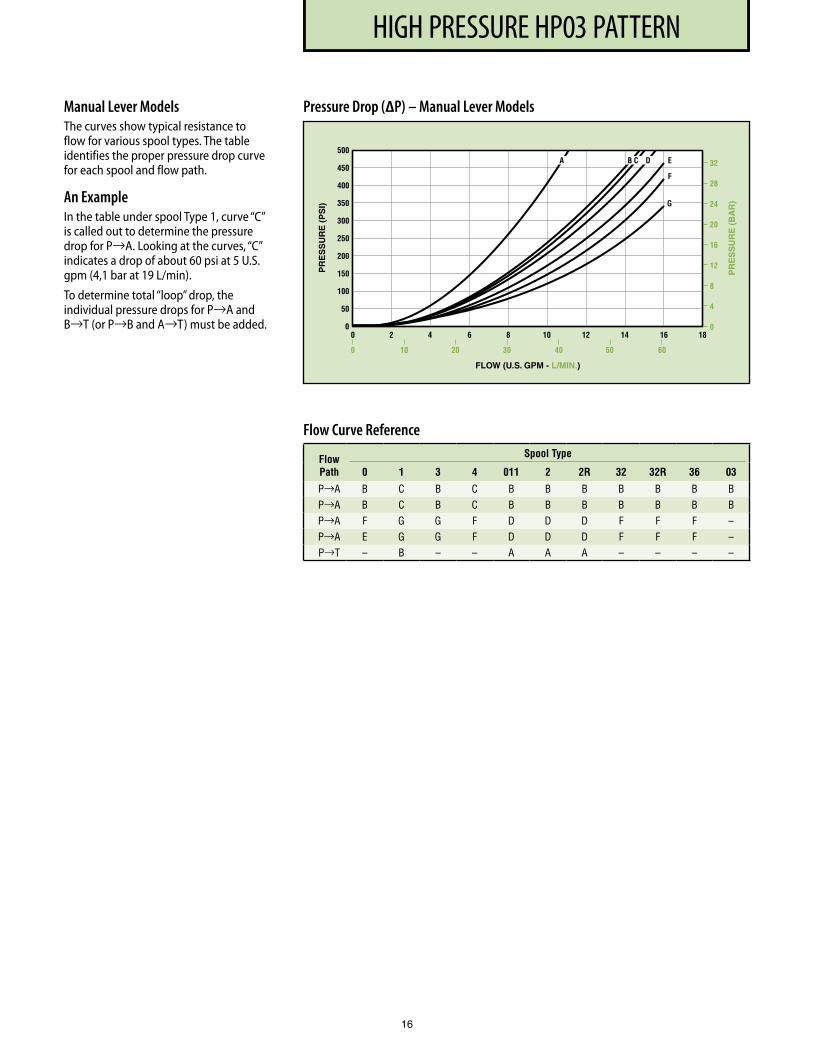
Flow Curve Reference
Flow Path
Spool Type
0 1 3 4 011 2 2R 32 32R 36 03
P→A B C B C B B B B B B B P→A B C B C B B B B B B B P→A F G G F D D D F F F – P→A E G G F D D D F F F – P→T – B – – A A A – – – –
Pressure Drop (∆P) – Manual Lever ModelsManual Lever ModelsThe curves show typical resistance to flow for various spool types. The table identifies the proper pressure drop curve for each spool and flow path.
An ExampleIn the table under spool Type 1, curve “C” is called out to determine the pressure drop for P→A. Looking at the curves, “C” indicates a drop of about 60 psi at 5 U.S. gpm (4,1 bar at 19 L/min).
To determine total “loop” drop, the individual pressure drops for P→A and B→T (or P→B and A→T) must be added.
PF3000 SERIES, 10 DESIGNHIGH PRESSURE HP03 PATTERN
17
.92 (23,4)
3.53 (89,7)
.13 (3,3)
1.59 (40,4)
1.30 (33,0)
3.12 (79,2) D.C. 2.51
(63,8) A.C.
.125 (3,18) LOCATING PIN
9.77 (248,2)
D.C. SOLENOID
8.54 (216,9)
A.C. SOLENOID
.94 (23,9)
1.88 (47,8)
SOLENOID A FOR TYPE 0, 1, 3, 4, 03,
32, 32R, 36 (20 OR 21 FOR CODE 1 OR 2
OPERATOR) SPOOLS; SOLENOID B FOR TYPE
011, 2, 2R SPOOLS
.250-20 U.N.C. THREADED x .75 (19,0) LONG MOUNTING BOLTS, 4 REQUIRED; TORQUE: 12 LB • FT (16,3 N • M)
5.00 (127,0)
1/2- 14 N.P.T. STANDARD ELECTRIC ENTRY, 1 EACH END
2.30 (58,4)
D.C.
CLEARANCE TO REMOVE COIL
.38 (9,7) GRIP
2.74 (69,6)
3.73 (94,7)
MANUAL ACTUATOR PI N
1.68 (42,7)
A.C.
.37 (9,4)
.88 (22,4)
1.75 (44,4)
1.250 (31,75)
.25 (6,4)
SOLENOID B FOR TYPE 0, 1, 3, 4, 03, 32, 32R, 36 (20 OR 21 FOR CODE 1 OR 2 OPERATOR) SPOOLS; SOLENOID A FOR TYPE 011, 2, 2R SPOOLS
6500 Series, Double Solenoid Models
SPACERNO. 10811320
SOLENOID A FOR TYPE0, 1, 3, 4, 03, 32, 32R, 36
(20 OR 21 FOR CODE 1 OR2 OPERATOR) SPOOLS
.92(23,4)
3.53(89,7)
.13(3,3)
1.59(40,4)
1.30(33,0) ∅.125 (3,18)
LOCATING PIN
1.13(28,7)GRIP
.250-20 U.N.C. THREADEDx 1.50 (38,1) LONGMOUNTING BOLTS,
4 REQUIRED;TORQUE: 12 LB •FT (16,3 N •M)
1.69(42,9)
.74(18,8)
4.45(113,0)
12.43(315,7)
MANUALACTUATOR PIN
3.72(94,5)
∅ 2.88(73.2)
1/2-14 N.P.T. STANDARD ELECTRIC ENTRY,360˚ ROTATABLE WITH BOTTOM OUTLET SUBPLATE
NOTE: KEEP AIR GAPBETWEEN SOLENOIDAND VALVE BODY CLEAN
GROUNDWIRE (2) TYPICAL #18 AWG(GREEN INSULATION)
APPROXIMATELY 18 (457) LONG
LEADWIRES (4) TYPICAL#18 AWG, APPROXIMATELY 18 (457) LONG
1.63(41,4)
45˚
SOLENOID B FOR TYPE0, 1, 3, 4, 03, 32, 32R, 36
(20 OR 21 FOR CODE 1 OR2 OPERATOR) SPOOLS
SOLENOID A FORTYPE 011, 2,2R SPOOLS
SOLENOID B FORTYPE 011, 2,2R SPOOLS
1.75(44,4)
.88(22,4)
3.43(87,1)
CLEARANCE TOREMOVE COIL
SOLENOID POSITION LIMITWITH SIDE OUTLET SUBPLATE
.37(9,4)
1.250(31,75)
.25(6,4)
6500 Series, Double “EP” Solenoid Models
INSTALLATION AND DIMENSIONS
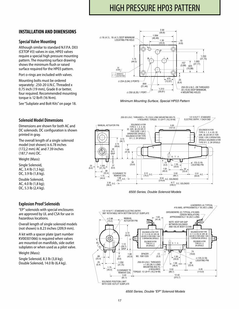
Special Valve MountingAlthough similar to standard N.F.P.A. D03 (CETOP #3) valves in size, HP03 valves require a special high pressure mounting pattern. The mounting surface drawing shows the minimum flush or raised surface required for the HP03 pattern.
Port o-rings are included with valves.
Mounting bolts must be ordered separately: .250-20 U.N.C. Threaded x 0.75 inch (19 mm), Grade 8 or better, four required. Recommended mounting torque is 12 lb•ft (16 N•m).
See “Subplate and Bolt Kits” on page 18.
Solenoid Model DimensionsDimensions are shown for both AC and DC solenoids. DC configuration is shown printed in gray.
The overall length of a single solenoid model (not shown) is 6.78 inches (172,2 mm) AC and 7.39 inches (187,7 mm) DC.
Weight (Mass):
Single Solenoid, AC, 3.4 lb (1,5 kg); DC, 3.9 lb (1,8 kg).
Double Solenoid, AC, 4.0 lb (1,8 kg); DC, 5.3 lb (2,4 kg).
Explosion Proof Solenoids“EP” solenoids with special enclosures are approved by UL and CSA for use in hazardous locations.
Overall length of single solenoid models (not shown) is 8.23 inches (209,9 mm).
A kit with a spacer plate (part number KV00301066) is required when valves are mounted on manifolds, side outlet subplates or when used as a pilot valve.
Weight (Mass):
Single Solenoid, 8.3 lb (3,8 kg); Double Solenoid, 14.0 lb (6,4 kg).
Minimum Mounting Surface, Special HP03 Pattern
∅.16 (4,1); .16 (4,1) DEEP MINIMUMLOCATING PIN HOLE
1.75(44,5)
∅.234 (5,94) 3 PORTS
1.30(33,0)
1.594(40,49)
2.00(50,8)
.19(4,8)
.25(6,4)
.157(3,99) .625
(15,88)
1.093(27,77)
1.250(31,75)
.475(12,07)
.844(21,44)
1.213(30,81)
.250-20 U.N.C.–2B THREADED
.43 (10,9) DEEP MINIMUM,4 MOUNTING HOLES∅.250 (6,35) 1 PORT
P
AB
T.0004/4.0(0,010/102)
32(0,80)
PF3000 SERIES, 10 DESIGNHIGH PRESSURE HP03 PATTERN
18
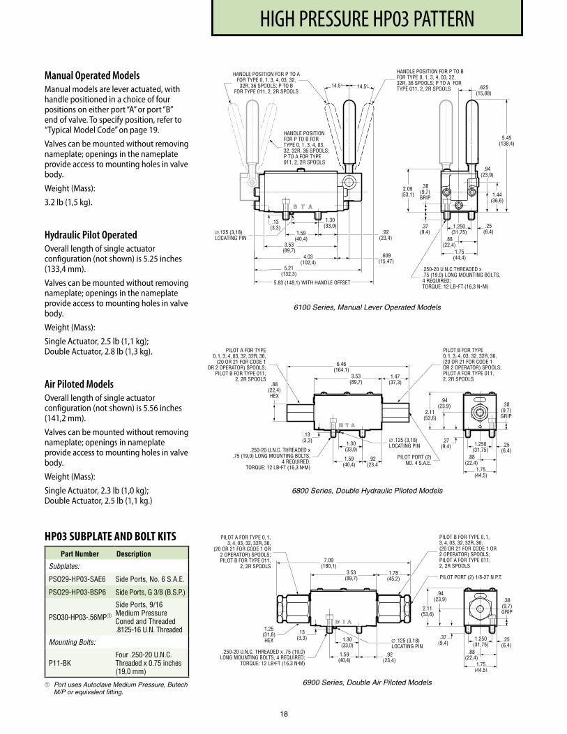
Manual Operated ModelsManual models are lever actuated, with handle positioned in a choice of four positions on either port “A” or port “B” end of valve. To specify position, refer to “Typical Model Code” on page 19.
Valves can be mounted without removing nameplate; openings in the name plate provide access to mounting holes in valve body.
Weight (Mass):
3.2 lb (1,5 kg).
Hydraulic Pilot OperatedOverall length of single actuator configuration (not shown) is 5.25 inches (133,4 mm).
Valves can be mounted without removing nameplate; openings in the name plate provide access to mounting holes in valve body.
Weight (Mass):
Single Actuator, 2.5 lb (1,1 kg); Double Actuator, 2.8 lb (1,3 kg).
Air Piloted ModelsOverall length of single actuator configuration (not shown) is 5.56 inches (141,2 mm).
Valves can be mounted without removing nameplate; openings in name plate provide access to mounting holes in valve body.
Weight (Mass):
Single Actuator, 2.3 lb (1,0 kg); Double Actuator, 2.5 lb (1,1 kg.)
PILOT PORT (2) 1/8-27 N .P .T .
.92(23,4)
.13(3,3) ∅ .125 (3,18)
LOCATING PIN1 .59
(40,4)
1 .25(31,8)HEX
7 .09(180,1)
1 .78(45,2)
1 .75(44,5)
.88(22,4)
2 .11(53,6)
.94(23,9)
.37(9,4)
.38(9,7)GRIP
.250-20 U .N .C . THREADED x .75 (19,0)LONG MOUNTING BOLTS, 4 REQUIRED;
TORQUE: 12 LB•FT (16,3 N•M)
PILOT A FOR TYPE 0, 1, 3, 4, 03, 32, 32R, 36,
(20 OR 21 FOR CODE 1 OR2 OPERATOR) SPOOLS;PILOT B FOR TYPE 011,
2, 2R SPOOLS
PILOT B FOR TYPE 0, 1,3, 4, 03, 32, 32R, 36,(20 OR 21 FOR CODE 1 OR2 OPERATOR) SPOOLS;PILOT A FOR TYPE 011,2, 2R SPOOLS
3 .53(89,7)
1 .30(33,0)
.25(6,4)
1 .250(31,75)
6900 Series, Double Air Piloted Models
HANDLE POSITION FOR P TO A FOR TYPE 0, 1, 3, 4, 03, 32,
32R, 36 SPOOLS; P TO B FOR TYPE 011, 2, 2R SPOOL S
HANDLE POSITION F OR P TO B F OR TYPE 0, 1, 3, 4, 03, 32, 32R, 36 SPOOLS; P TO A FO R TYPE 011, 2, 2R SPOOLS
2.09 (53,1)
1.75 (44,4)
.94 (23,9)
1.44 (36,6)
5.45 (138,4)
.250-20 U.N.C.THREADED x
.75 (19,0) LONG MOUNTING BOLTS, 4 REQUIRED; TORQUE: 12 LB • FT (16,3 N • M)
.38 (9,7) GRIP
.37 (9,4 )
.88 (22,4)
14.5 ° 14.5 °
HANDLE POSITION FOR P TO B FOR TYPE 0, 1, 3, 4, 03, 32, 32R, 36 SPOOLS; P TO A FOR TYPE 011, 2, 2R SPOOLS
1.30 (33,0)
1.59 (40,4)
3.53 (89,7)
4.03 (102,4)
5.21 (132,3)
5.83 (148,1) WITH HANDLE OFFSET
∅.125 (3,18) LOCATING PIN
.13 (3,3)
.92 (23,4)
.25 (6,4 )
1.250 (31,75)
.609 (15,47)
.625 (15,88)
6100 Series, Manual Lever Operated Models
PILOT PORT (2)NO. 4 S.A.E.
6.46(164,1)
1.47(37,3).88
(22,4)HEX
2.11(53,6)
.94(23,9)
.37(9,4)
.92(23,4
.13(3,3) ∅ .125 (3,18)
LOCATING PIN
1.59(40,4)
1.30(33,0)
.38(9,7)GRIP
.250-20 U.N.C. THREADED x.75 (19,0) LONG MOUNTING BOLTS,
4 REQUIRED;TORQUE: 12 LB•FT (16,3 N•M)
PILOT A FOR TYPE0, 1, 3, 4, 03, 32, 32R, 36,
(20 OR 21 FOR CODE 1OR 2 OPERATOR) SPOOLS;
PILOT B FOR TYPE 011,2, 2R SPOOLS
PILOT B FOR TYPE0, 1, 3, 4, 03, 32, 32R, 36,(20 OR 21 FOR CODE 1OR 2 OPERATOR) SPOOLS;PILOT A FOR TYPE 011,2, 2R SPOOLS3.53
(89,7)
1.75(44,5)
.88(22,4)
.25(6,4)
1.250(31,75)
6800 Series, Double Hydraulic Piloted Models
HP03 SUBPLATE AND BOLT KITSPart Number Description
Subplates:
PSO29-HP03-SAE6 Side Ports, No . 6 S .A .E .
PSO29-HP03-BSP6 Side Ports, G 3/8 (B .S .P .)
PSO30-HP03- .56MP
Side Ports, 9/16 Medium Pressure Coned and Threaded .8125-16 U .N . Threaded
Mounting Bolts:
P11-BKFour .250-20 U .N .C . Threaded x 0 .75 inches (19,0 mm)
Port uses Autoclave Medium Pressure, Butech M/P or equivalent fitting.
PF3000 SERIES, 10 DESIGNHIGH PRESSURE HP03 PATTERN
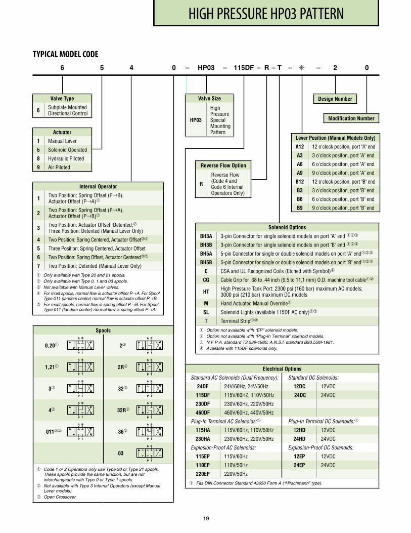
Actuator
1 Manual Lever
5 Solenoid Operated
8 Hydraulic Piloted
9 Air Piloted
6 5 4 0 – HP03 – 115DF – R – T – ✳ – 2 0
Valve Type
6 Subplate Mounted Directional Control
Design Number
Modification Number
TYPICAL MODEL CODE
Electrical Options
Standard AC Solenoids (Dual Frequency): Standard DC Solenoids:
24DF 24V/60Hz, 24V/50Hz 12DC 12VDC
115DF 115V/60HZ, 110V/50Hz 24DC 24VDC
230DF 230V/60Hz, 220V/50Hz
460DF 460V/60Hz, 440V/50Hz
Plug-In Terminal AC Solenoids: Plug-In Terminal DC Solenoids:
115HA 115V/60Hz, 110V/50Hz 12HD 12VDC
230HA 230V/60Hz, 220V/50Hz 24HD 24VDC
Explosion-Proof AC Solenoids: Explosion-Proof DC Solenoids:
115EP 115V/60Hz 12EP 12VDC
110EP 110V/50Hz 24EP 24VDC
220EP 220V/50Hz
Fits DIN Connector Standard 43650 Form A (“Hirschmann” type).
Reverse Flow Option
R
Reverse Flow (Code 4 and Code 6 Internal Operators Only)
19
Spools
0,20 2
1,21 2R
3 32
4 32R
011➂ 36
03
Code 1 or 2 Operators only use Type 20 or Type 21 spools. These spools provide the same function, but are not interchangeable with Type 0 or Type 1 spools.
Not available with Type 3 Internal Operators (except Manual Lever models).
➂ Open Crossover.
A B
P T
A B
P T
A B
P T
A B
P T
A B
P T
A B
P T
A B
P T
A B
P T
A B
P T
A B
P T
A B
P T
Valve Size
HP03
High Pressure Special Mounting Pattern
Internal Operator
1 Two Position: Spring Offset (P→B), Actuator Offset (P→A)
2 Two Position: Spring Offset (P→A), Actuator Offset (P→B)
3 Two Position: Actuator Offset, Detented;Three Position: Detented (Manual Lever Only)
4 Two Position: Spring Centered, Actuator Offset➂➃
5 Three Position: Spring Centered, Actuator Offset
6 Two Position: Spring Offset, Actuator Centered➂➄
7 Two Position: Detented (Manual Lever Only)
Only available with Type 20 and 21 spools. Only available with Type 0, 1 and 03 spools.➂ Not available with Manual Lever valves.➃ For most spools, normal flow is actuator offset P→A. For Spool
Type 011 (tandem center) normal flow is actuator offset P→B. ➄ For most spools, normal flow is spring offset P→B. For Spool
Type 011 (tandem center) normal flow is spring offset P→A.
Lever Position (Manual Models Only)
A12 12 o'clock positon, port "A" end
A3 3 o'clock positon, port "A" end
A6 6 o'clock positon, port "A" end
A9 9 o'clock positon, port "A" end
B12 12 o'clock positon, port "B" end
B3 3 o'clock positon, port "B" end
B6 6 o'clock positon, port "B" end
B9 9 o'clock positon, port "B" end
Solenoid Options
BH3A 3-pin Connector for single solenoid models on port "A" end ➂
BH3B 3-pin Connector for single solenoid models on port "B" end ➂
BH5A 5-pin Connector for single or double solenoid models on port "A" end➂
BH5B 5-pin Connector for single or double solenoid models on port "B" end➂
C CSA and UL Recognized Coils (Etched with Symbol)➃
CG Cable Grip for .38 to .44 inch (9,5 to 11,1 mm) O .D . machine tool cable
HT High Pressure Tank Port: 2300 psi (160 bar) maximum AC models; 3000 psi (210 bar) maximum DC models
M Hand Actuated Manual Override
SL Solenoid Lights (available 115DF AC only)
T Terminal Strip
Option not available with “EP” solenoid models. Option not available with “Plug-In Terminal” solenoid models. ➂ N.F.P.A. standard T3.539-1980; A.N.S.I. standard B93.55M-1981. ➃ Available with 115DF solenoids only.
PF3000 SERIES, 10 DESIGND05 PATTERN
20
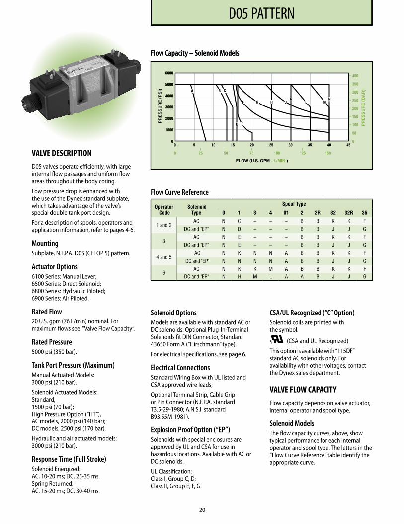
VALVE DESCRIPTIOND05 valves operate efficiently, with large internal flow passages and uniform flow areas throughout the body coring.
Low pressure drop is enhanced with the use of the Dynex standard subplate, which takes advantage of the valve’s special double tank port design.
For a description of spools, operators and application information, refer to pages 4-6.
MountingSubplate, N.F.P.A. D05 (CETOP 5) pattern.
Actuator Options6100 Series: Manual Lever; 6500 Series: Direct Solenoid; 6800 Series: Hydraulic Piloted; 6900 Series: Air Piloted.
Rated Flow20 U.S. gpm (76 L/min) nominal. For maximum flows see “Valve Flow Capacity”.
Rated Pressure5000 psi (350 bar).
Tank Port Pressure (Maximum)Manual Actuated Models: 3000 psi (210 bar).
Solenoid Actuated Models: Standard, 1500 psi (70 bar); High Pressure Option (“HT”), AC models, 2000 psi (140 bar); DC models, 2500 psi (170 bar).
Hydraulic and air actuated models: 3000 psi (210 bar).
Response Time (Full Stroke)Solenoid Energized: AC, 10-20 ms; DC, 25-35 ms. Spring Returned: AC, 15-20 ms; DC, 30-40 ms.
Flow Curve Reference
Operator Code
Solenoid Type
Spool Type
0 1 3 4 01 2 2R 32 32R 36
1 and 2AC N C – – – B B K K F
DC and "EP" N D – – – B B J J G
3AC N E – – – B B K K F
DC and "EP" N E – – – B B J J G
4 and 5AC N K N N A B B K K F
DC and "EP" N N N N A B B J J G
6AC N K K M A B B K K F
DC and "EP" N H M L A A B J J G
Solenoid OptionsModels are available with standard AC or DC solenoids. Optional Plug-In-Terminal Solenoids fit DIN Connector, Standard 43650 Form A (“Hirschmann” type).
For electrical specifications, see page 6.
Electrical ConnectionsStandard Wiring Box with UL listed and CSA approved wire leads;
Optional Terminal Strip, Cable Grip or Pin Connector (N.F.P.A. standard T3.5-29-1980; A.N.S.I. standard B93,55M-1981).
Explosion Proof Option (“EP”)Solenoids with special enclosures are approved by UL and CSA for use in hazardous locations. Available with AC or DC solenoids.
UL Classification: Class I, Group C, D; Class II, Group E, F, G.
CSA/UL Recognized (“C” Option)Solenoid coils are printed with the symbol:
®C (CSA and UL Recognized)
This option is available with “115DF” standard AC solenoids only. For availability with other voltages, contact the Dynex sales department.
VALVE FLOW CAPACITYFlow capacity depends on valve actuator, internal operator and spool type.
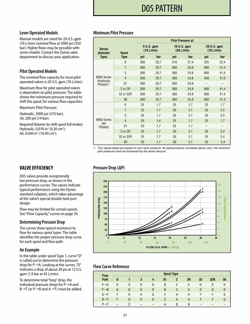
Solenoid ModelsThe flow capacity curves, above, show typical performance for each internal operator and spool type. The letters in the “Flow Curve Reference” table identify the appropriate curve.
Flow Capacity – Solenoid ModelsFlow Capacity – Solenoid Models
PR
ES
SU
RE
(P
SI)
FLOW (U.S. GPM - L/MIN.)
PR
ES
SU
RE
(B
AR
)
400
350
300
250
200
150
100
50
00 5 10 15 20 25 30 35 40 45
0
1000
2000
3000
4000
5000
6000
0 25 50 75 100 125 150
A B C
F G H J L MN
ED
K
PF3000 SERIES, 10 DESIGND05 PATTERN
21
Minimum Pilot Pressure
Series (Actuator
Type)Spool Type
Pilot Pressure at:
5 U.S. gpm (19 L/min)
10 U.S. gpm (38 L/min)
20 U.S. gpm (76 L/min)
psi bar psi bar psi bar
6800 Series(Hydraulic Piloted)
0 300 20,7 310 21,4 325 22,4
1 300 20,7 360 24,8 600 41,4
3 300 20,7 360 24,8 600 41,4
4 300 20,7 360 24,8 450 31,0
01 300 20,7 360 24,8 – –
2 or 2R 300 20,7 360 24,8 600 41,4
32 or 32R 300 20,7 360 24,8 600 41,4
36 300 20,7 360 24,8 600 41,4
6900 Series (Air
Piloted)
0 25 1,7 25 1,7 25 1,7
1 25 1,7 30 2,1 35 2,4
3 25 1,7 30 2,1 35 2,4
4 20 1,4 25 1,7 25 1,7
01 23 1,7 25 1,7 – –
2 or 2R 23 1,7 30 2,1 35 2,4
32 or 32R 25 1,7 30 2,1 35 2,4
36 25 1,7 30 2,1 35 2,4
The values listed are based on zero tank pressure. As back-pressure increases above zero, the minimum pilot pressure must be increased by the same amount.
Lever Operated ModelsManual models are rated for 20 U.S. gpm (76 L/min) nominal flow at 5000 psi (350 bar). Higher flows may be possible with some models. Contact the Dynex sales department to discuss your application.
Pilot Operated ModelsThe nominal flow capacity for most pilot operated valves is 20 U.S. gpm (76 L/min).
Maximum flow for pilot operated valves is dependent on pilot pressure. The table shows the minimum pressure required to shift the spool, for various flow capacities.
Maximum Pilot Pressure:
Hydraulic, 3000 psi (210 bar); Air, 200 psi (14 bar).
Required Volume (to shift spool full stroke): Hydraulic, 0.018 in3 (0,30 cm3); Air, 0.640 in3 (10,49 cm3).
Flow Curve Reference
Flow Path
Spool Type
0 1 3 4 01 2 2R 32 32R 36
P→A D D D D B C C D D D P→B D D D D B C C D D D A→T F H H G E H H F F G B→T F H H G E H H F F G P→T – D – – A B B – – –
VALVE EFFICIENCYD05 valves provide exceptionally low pressure drop, as shown in the performance curves. The values indicate typical performance using the Dynex standard subplate, which takes advantage of the valve’s special double tank port design.
Flow may be limited for certain spools. See “Flow Capacity” curves on page 20.
Determining Pressure DropThe curves show typical resistance to flow for various spool types. The table identifies the proper pressure drop curve for each spool and flow path.
An ExampleIn the table under spool Type 1, curve “D” is called out to determine the pressure drop for P→A. Looking at the curves, “D” indicates a drop of about 28 psi at 12 U.S. gpm (1,9 bar at 45 L/min).
To determine total “loop” drop, the individual pressure drops for P→A and B→T (or P→B and A→T) must be added.
Pressure Drop (∆P)
PF3000 SERIES, 10 DESIGND05 PATTERN
22
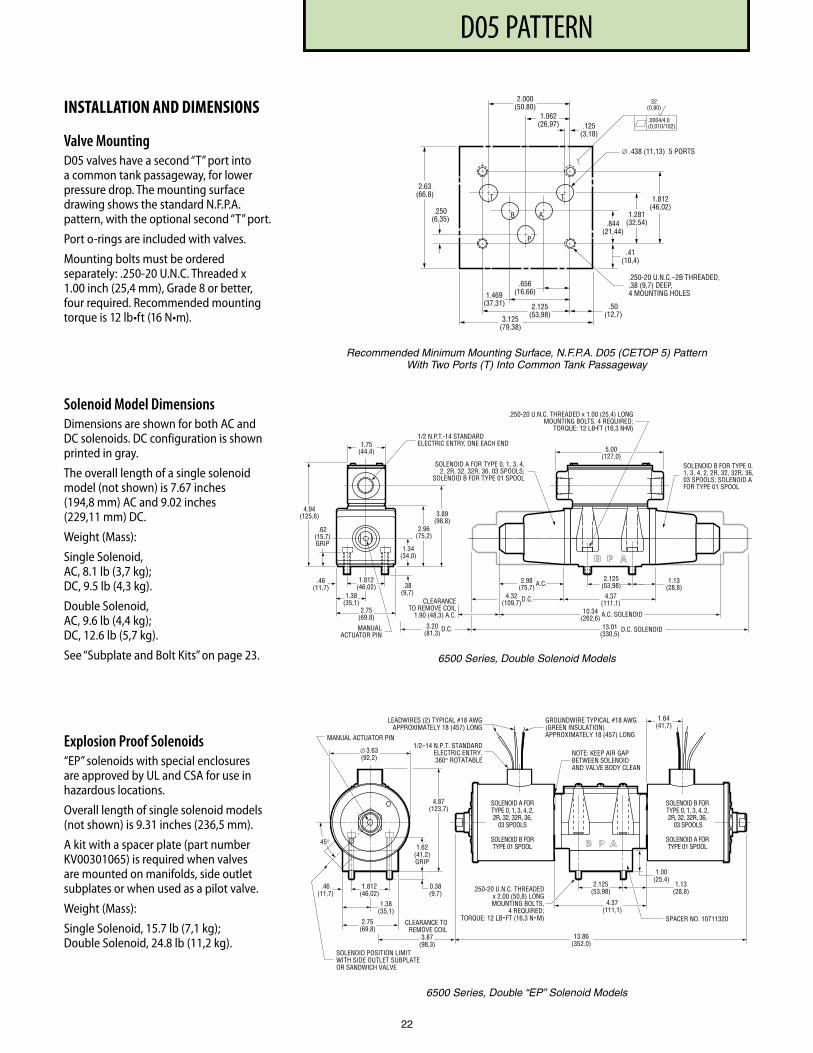
INSTALLATION AND DIMENSIONS
Valve MountingD05 valves have a second “T” port into a common tank passageway, for lower pressure drop. The mounting surface drawing shows the standard N.F.P.A. pattern, with the optional second “T” port.
Port o-rings are included with valves.
Mounting bolts must be ordered separately: .250-20 U.N.C. Threaded x 1.00 inch (25,4 mm), Grade 8 or better, four required. Recommended mounting torque is 12 lb•ft (16 N•m).
Solenoid Model DimensionsDimensions are shown for both AC and DC solenoids. DC configuration is shown printed in gray.
The overall length of a single solenoid model (not shown) is 7.67 inches (194,8 mm) AC and 9.02 inches (229,11 mm) DC.
Weight (Mass):
Single Solenoid, AC, 8.1 lb (3,7 kg); DC, 9.5 lb (4,3 kg).
Double Solenoid, AC, 9.6 lb (4,4 kg); DC, 12.6 lb (5,7 kg).
See “Subplate and Bolt Kits” on page 23.
Explosion Proof Solenoids“EP” solenoids with special enclosures are approved by UL and CSA for use in hazardous locations.
Overall length of single solenoid models (not shown) is 9.31 inches (236,5 mm).
A kit with a spacer plate (part number KV00301065) is required when valves are mounted on manifolds, side outlet subplates or when used as a pilot valve.
Weight (Mass):
Single Solenoid, 15.7 lb (7,1 kg); Double Solenoid, 24.8 lb (11,2 kg).
Recommended Minimum Mounting Surface, N.F.P.A. D05 (CETOP 5) Pattern With Two Ports (T) Into Common Tank Passageway
6500 Series, Double Solenoid Models
6500 Series, Double “EP” Solenoid Models
1 .062(26,97) .125
(3,18)
∅ .438 (11,13) 5 PORTS
.41(10,4)
.844(21,44)
1 .281(32,54)
1 .812(46,02)
.250-20 U .N .C .–2B THREADED, .38 (9,7) DEEP,4 MOUNTING HOLES
T T
B A
P
2 .000(50 .80)
.250(6,35)
2 .63(66,8)
.656(16,66)
.50(12,7)
1 .469(37,31) 2 .125
(53,98)3 .125(79,38)
.0004/4 .0(0,010/102)
32(0,80)
4.37(111,1)
2.125(53,98)
1.13(28,8)
SOLENOID A FORTYPE 0, 1, 3, 4, 2,2R, 32, 32R, 36,
03 SPOOLS
SOLENOID B FORTYPE 01 SPOOL
SOLENOID B FORTYPE 0, 1, 3, 4, 2,2R, 32, 32R, 36,
03 SPOOLS
SOLENOID A FORTYPE 01 SPOOL
13.86(352,0)
45°
0.38(9,7)
1.00(25,4)
1.62(41,2)GRIP
4.87(123,7)
SOLENOID POSITION LIMITWITH SIDE OUTLET SUBPLATEOR SANDWICH VALVE
1.812(46,02)
MANUAL ACTUATOR PIN1/2–14 N.P.T. STANDARD
ELECTRIC ENTRY,360° ROTATABLE
NOTE: KEEP AIR GAPBETWEEN SOLENOIDAND VALVE BODY CLEAN
GROUNDWIRE TYPICAL #18 AWG(GREEN INSULATION)APPROXIMATELY 18 (457) LONG
LEADWIRES (2) TYPICAL #18 AWGAPPROXIMATELY 18 (457) LONG
∅ 3.63(92,2)
1.64(41,7)
3.87(98,3)
CLEARANCE TOREMOVE COIL
.250-20 U.N.C. THREADEDx 2.00 (50,8) LONGMOUNTING BOLTS,
4 REQUIRED;TORQUE: 12 LB • FT (16,3 N • M) SPACER NO. 10711320
1.38(35,1)
2.75(69,8)
.46(11,7)
1.13 (28,8)
2.125 (53,98)
4.37 (111,1)
2.98 (75,7)
4.32 (109,7)
3.20 (81,3)
CLEARANCE TO REMOVE COIL
1.90 (48,3) A.C. 10.34 (262,6)
13.01 (330,5)
5.00 (127,0)
1/2 N.P .T .-14 ST ANDARD ELECTRIC ENTR Y, ONE EACH END
2.96 (75,2)
.38 (9,7)
.62 (15,7) GRIP
1.34 (34,0)
3.89 (98,8)
.250-20 U.N.C. THREADED x 1.00 (25,4) LONG MOUNTING BOL TS, 4 REQUIRED;
TORQUE: 12 LB • FT (16,3 N • M)
MANUAL ACTUA TOR PIN
4.94 (125,6)
D.C.
A.C.
D.C.
A.C. SOLENOID
1.75 (44,4)
2.75 (69,8)
1.38 (35,1)
D.C. SOLENOID
SOLENOID A FOR TYPE 0, 1, 3, 4, 2, 2R, 32, 32R, 36, 03 SPOOLS;
SOLENOID B FOR TYPE 01 SPOOL
SOLENOID B FOR TYPE 0, 1, 3, 4, 2, 2R, 32, 32R, 36, 03 SPOOLS; SOLENOID A FOR TYPE 01 SPOOL
.46 (11,7)
1.812 (46,02)

PF3000 SERIES, 10 DESIGND05 PATTERN
23
D05 SUBPLATE AND BOLT KITSPart Number Description
Subplates:
P23-D05- .50 Bottom Ports, 1/2-14 N .P .T .F .
P28-D05- .75 Bottom Ports, 3/4-14 N .P .T .F .
P28-D05-SAE12 Bottom Ports, No . 12 S .A .E .
PSO11-D05- .50 Side Ports, 1/2-14 N .P .T .F .
PSO28-D05- .75 Side Ports, 3/4-14 N .P .T .F .
PSO11-D05-SAE8 Side Ports, No . 8 S .A .E .
PSO28-D05-SAE12 Side Ports, No . 12 S .A .E .
Bolt Kit:
P22-BKFour .250-20 U .N .C . Threaded x 1 .00 inch (25,4 mm)
Manual Operated ModelsManual models are lever actuated, with handle positioned in a choice of four positions on either port “A” or port “B” end of valve. To specify position, refer to “Typical Model Code” on page 24.
The location of the handle can be changed by removing the bracket and handle assembly and rotating it to the desired position.
Weight (Mass):
7.8 lb (3,5 kg).
Hydraulic Pilot OperatedOverall length of single actuator configuration (not shown) is 6.60 inches (167,6 mm).
Weight (Mass):
Single Actuator, 7.1 lb (3,2 kg); Double Actuator, 7.8 lb (3,5 kg).
Air Piloted ModelsOverall length of single actuator configuration (not shown) is 7.13 inches (167,6 mm).
Weight (Mass):
Single Actuator, 8.0 lb (3,6 kg); Double Actuator, 9.5 lb (4,3 kg).
4.37(111,1)
.62(15,7)GRIP
.38(9,7)
.46(11,7)
1.38(35,1)
2.75(69,8)
1.34(34,0)
3.19(81,0)
2.125(53,98)
1.13(28,8)
9.49(241,0)
2.56(65,0)
PILOT A FOR TYPE 0, 1, 3, 4,2, 2R, 32, 32R, 36, 03 SPOOLS;
PILOT B FOR TYPE 01 SPOOL
PILOT B FOR TYPE 0, 1, 3, 4,2, 2R, 32, 32R, 36, 03 SPOOLS;
PILOT A FOR TYPE 01 SPOOL1.88
(47,8)HEX
PILOT PORTS (2)NO. 6 S.A.E.
.250-20 U.N.C. THREADED x 1.00(25,4) LONG MOUNTING BOLTS,
4 REQUIRED; TORQUE:12 LB • IN (16,3 N • M)
1.812(46,02)
6900 Series, Double Air Piloted Models
4.37(111,1)
.62(15,7)GRIP
1.34(34,0)
3.19(81,0)
2.125(53,98)
1.13(28,8)
8.43(214,1)
2.03(51,6)
PILOT A FOR TYPE 0, 1, 3, 4,2, 2R, 32, 32R, 36, 03 SPOOLS;
PILOT B FOR TYPE 01 SPOOL
PILOT B FOR TYPE 0, 1, 3, 4,2, 2R, 32, 32R, 36, 03 SPOOLS;
PILOT A FOR TYPE 01 SPOOL1.25
(31,8)HEX
PILOT PORTS (2)NO. 6 S.A.E.
.250-20 U.N.C. THREADED x1.00 (25,4) LONG MOUNTING BOLTS,
4 REQUIRED;TORQUE: 12 LB • IN ( 16,3 N • M)
.38(9,7)
.46(11,7)
1.38(35,1)
2.75(69,8)
1.812(46,02)
6800 Series, Double Hydraulic Piloted Models
HANDLE POSITION FOR P TO B FOR TYPE 0, 1, 3, 4, 2, 2R, 32, 32R, 36, 03 SPOOLS; P TO A FOR TYPE 01 SPOOL
19 º 19 º
7º
1.13 (28,8)
4.37 (111,1)
8.41 (213,7)
6.26 (159,1)
.71 (18,0)
7.80 (198,1)
.62 (15,7) GRIP
.38 (9,7)
1.34 (34,0)
1.84 (46,7)
3.19 (81,0)
.84 (21,3)
.250-20 U.N.C. THREADED x 1.0 (25,4) LONG
MOUNTING BOL TS, 4 REQUIRED;
TORQUE: 12 LB • FT (16,3 N • M)
HANDLE POSITION FOR P TO A FOR TYPE 0, 1, 3, 4, 2, 2R, 32, 32R, 36, 03 SPOOLS; P TO B FOR TYPE 01 SPOOLS
HANDLE POSITION FOR CENTER
FLOW FUNCTIONS
HANDLE POSITION FOR P TO B FOR TYPE 0, 1, 3, 4, 2, 2R, 32, 32R, 36, 03 SPOOLS; P TO A FOR TYPE 01 SPOOL
2.75 (69,8)
1.38 (35,1)
.46 (11,7)
1.812 (46,02)
2.125 (53,98)
6100 Series, Manual Lever Operated

PF3000 SERIES, 10 DESIGND05 PATTERN
Actuator
1 Manual Lever
5 Solenoid Operated
8 Hydraulic Piloted
9 Air Piloted
6 5 4 0 – D05 – 115DF – R – T – ✳ – 1 0
Valve Type
6 Subplate Mounted Directional Control
Design Number
Modification Number
TYPICAL MODEL CODE
Spools
0 2
1 2R
3 32
4 32R
01 36
03
Not available with Type 3 Internal Operators (except Manual Lever models).
Closed Crossover.
Electrical (Solenoid Options)
Standard AC Solenoids (Dual Frequency): Standard DC Solenoids:
24DF 24V/60Hz, 24V/50Hz 12DC 12VDC
115DF 115V/60HZ, 110V/50Hz 24DC 24VDC
230DF 230V/60Hz, 220V/50Hz 250DC 250VDC
460DF 460V/60Hz, 440V/50Hz
Plug-In Terminal AC Solenoids: Plug-In Terminal DC Solenoids:
115HA 115V/60Hz, 110V/50Hz 12HD 12VDC
230HA 230V/60Hz, 220V/50Hz 24HD 24VDC
Explosion-Proof AC Solenoids: Explosion-Proof DC Solenoids:
115EP 115V/60Hz 12EP 12VDC
110EP 110V/50Hz 24EP 24VDC
220EP 220V/50Hz
Fits DIN Connector Standard 43650 Form A (“Hirschmann” type).
Reverse Flow Option
R
Reverse Flow (Code 4 and Code 6 Internal Operators Only)
A B
P T
A B
P T
A B
P T
A B
P T
A B
P T
A B
P T
A B
P T
A B
P T
A B
P T
A B
P T
A B
P T
Valve Size
D05
N .F .P .A . D05 (CETOP 5) Mounting Pattern
24
Internal Operator
1 Two Position: Spring Offset (P→B), Actuator Offset (P→A)
2 Two Position: Spring Offset (P→A), Actuator Offset (P→B)
3 Two Position: Actuator Offset, Detented;Three Position: Detented (Manual Lever Only)
4 Two Position: Spring Centered, Actuator Offset➂
5 Three Position: Spring Centered, Actuator Offset
6 Two Position: Spring Offset, Actuator Centered➃
7 Two Position: Detented (Manual Lever Only)
Only available with Type 0, 1 and 03 spools. Not available with Manual Lever valves.➂ For most spools, normal flow is actuator offset P→A.
For Spool Type 01 (tandem center) normal flow is actuator offset P→B.
➃ For most spools, normal flow is spring offset P→B. For Spool Type 01 (tandem center) normal flow is spring offset P→A.
Lever Position (Manual Models Only)
A12 12 o'clock positon, port "A" end
A3 3 o'clock positon, port "A" end
A6 6 o'clock positon, port "A" end
A9 9 o'clock positon, port "A" end
B12 12 o'clock positon, port "B" end
B3 3 o'clock positon, port "B" end
B6 6 o'clock positon, port "B" end
B9 9 o'clock positon, port "B" end
Solenoid Options
BH3A 3-pin Connector for single solenoid models on port "A" end ➂
BH3B 3-pin Connector for single solenoid models on port "B" end ➂
BH5A 5-pin Connector for single or double solenoid models on port "A" end➂
BH5B 5-pin Connector for single or double solenoid models on port "B" end➂
C CSA and UL Recognized Coils (Etched with Symbol)➃
CG Cable Grip for .38 to .44 inch (9,5 to 11,1 mm) O .D . machine tool cable
HT High Pressure Tank Port: 2300 psi (160 bar) maximum AC models; 3000 psi (210 bar) maximum DC models
M Hand Actuated Manual Override
SL Solenoid Lights (available 115DF AC only)
T Terminal Strip
Option not available with “EP” solenoid models. Option not available with “Plug-In Terminal” solenoid models. ➂ N.F.P.A. standard T3.539-1980; A.N.S.I. standard B93.55M-1981. ➃ Available with 115DF solenoids only.
PF3000 SERIES, 10 DESIGNHIGH PRESSURE HP05 PATTERN
25
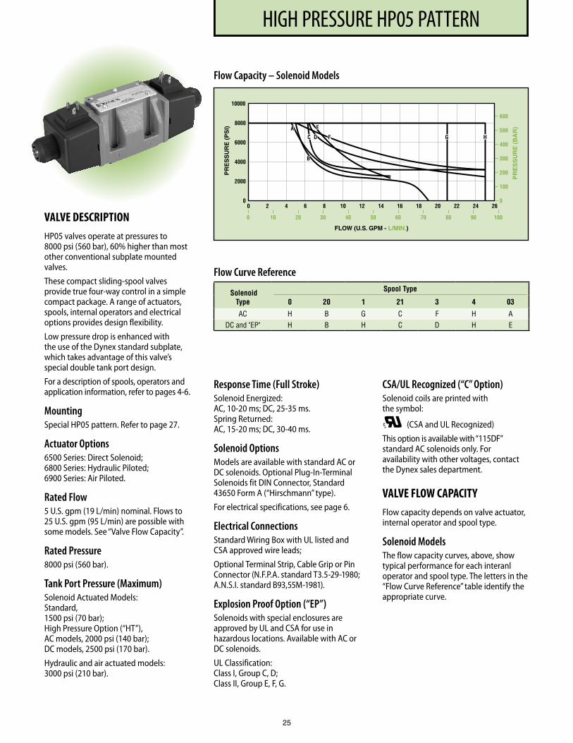
VALVE DESCRIPTIONHP05 valves operate at pressures to 8000 psi (560 bar), 60% higher than most other conventional subplate mounted valves.
These compact sliding-spool valves provide true four-way control in a simple compact package. A range of actuators, spools, internal operators and electrical options provides design flexibility.
Low pressure drop is enhanced with the use of the Dynex standard subplate, which takes advantage of this valve’s special double tank port design.
For a description of spools, operators and application information, refer to pages 4-6.
MountingSpecial HP05 pattern. Refer to page 27.
Actuator Options6500 Series: Direct Solenoid; 6800 Series: Hydraulic Piloted; 6900 Series: Air Piloted.
Rated Flow5 U.S. gpm (19 L/min) nominal. Flows to 25 U.S. gpm (95 L/min) are possible with some models. See “Valve Flow Capacity”.
Rated Pressure8000 psi (560 bar).
Tank Port Pressure (Maximum)Solenoid Actuated Models: Standard, 1500 psi (70 bar); High Pressure Option (“HT”), AC models, 2000 psi (140 bar); DC models, 2500 psi (170 bar).
Hydraulic and air actuated models: 3000 psi (210 bar).
Response Time (Full Stroke)Solenoid Energized: AC, 10-20 ms; DC, 25-35 ms. Spring Returned: AC, 15-20 ms; DC, 30-40 ms.
Solenoid OptionsModels are available with standard AC or DC solenoids. Optional Plug-In-Terminal Solenoids fit DIN Connector, Standard 43650 Form A (“Hirschmann” type).
For electrical specifications, see page 6.
Electrical ConnectionsStandard Wiring Box with UL listed and CSA approved wire leads;
Optional Terminal Strip, Cable Grip or Pin Connector (N.F.P.A. standard T3.5-29-1980; A.N.S.I. standard B93,55M-1981).
Explosion Proof Option (“EP”)Solenoids with special enclosures are approved by UL and CSA for use in hazardous locations. Available with AC or DC solenoids.
UL Classification: Class I, Group C, D; Class II, Group E, F, G.
CSA/UL Recognized (“C” Option)Solenoid coils are printed with the symbol:
®C (CSA and UL Recognized)
This option is available with “115DF” standard AC solenoids only. For availability with other voltages, contact the Dynex sales department.
VALVE FLOW CAPACITYFlow capacity depends on valve actuator, internal operator and spool type.
Solenoid ModelsThe flow capacity curves, above, show typical performance for each interanl operator and spool type. The letters in the “Flow Curve Reference” table identify the appropriate curve.
Flow Capacity – Solenoid Models
PR
ES
SU
RE
(P
SI)
FLOW (U.S. GPM - L/MIN.)
PR
ES
SU
RE
(B
AR
)
600
500
400
300
200
100
00 2 4 6 8 10 12 14 16 18 20 22 24 26
0
2000
4000
6000
8000
10000
0 10 20 30 40 50 60 70 80 90 100
HD F
A
B
C G
E
Flow Curve Reference
Solenoid Type
Spool Type
0 20 1 21 3 4 03
AC H B G C F H ADC and "EP" H B H C D H E
PF3000 SERIES, 10 DESIGNHIGH PRESSURE HP05
26
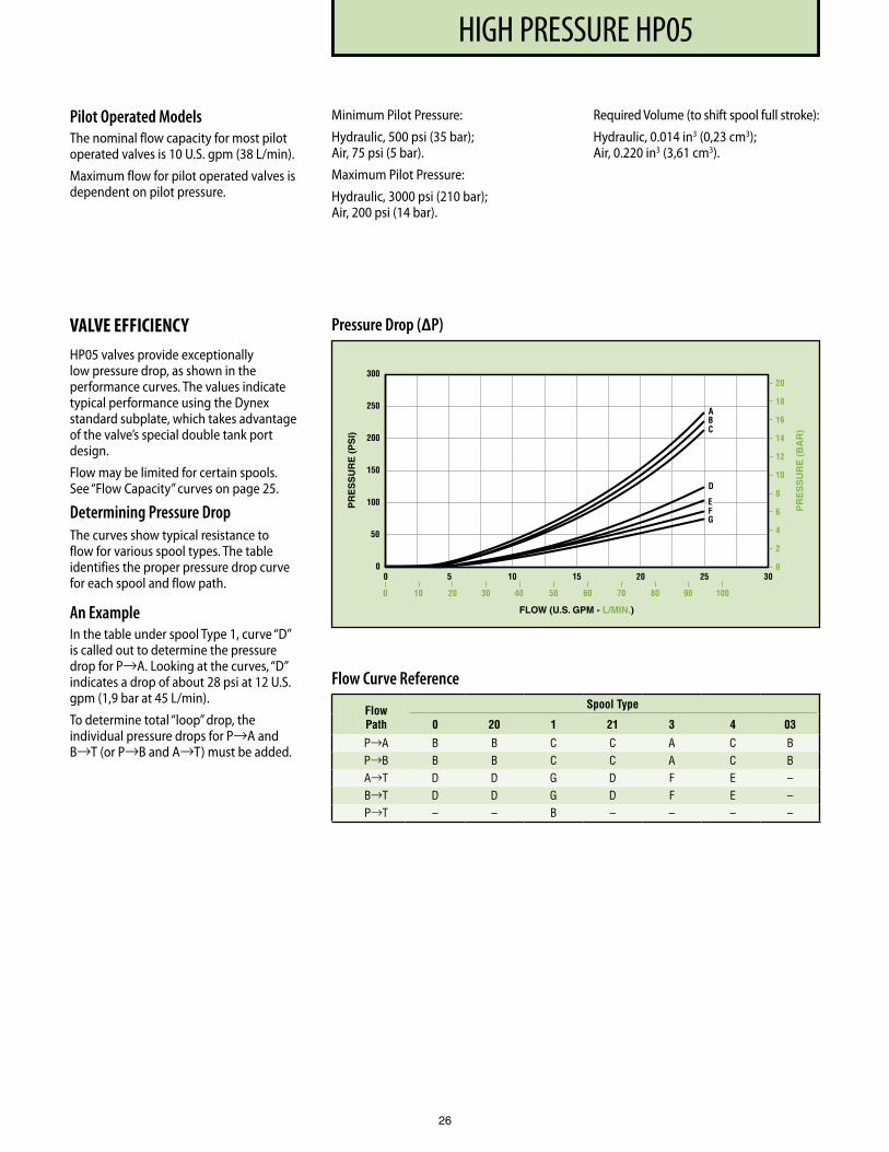
Pilot Operated ModelsThe nominal flow capacity for most pilot operated valves is 10 U.S. gpm (38 L/min).
Maximum flow for pilot operated valves is dependent on pilot pressure.
VALVE EFFICIENCYHP05 valves provide exceptionally low pressure drop, as shown in the performance curves. The values indicate typical performance using the Dynex standard subplate, which takes advantage of the valve’s special double tank port design.
Flow may be limited for certain spools. See “Flow Capacity” curves on page 25.
Determining Pressure DropThe curves show typical resistance to flow for various spool types. The table identifies the proper pressure drop curve for each spool and flow path.
An ExampleIn the table under spool Type 1, curve “D” is called out to determine the pressure drop for P→A. Looking at the curves, “D” indicates a drop of about 28 psi at 12 U.S. gpm (1,9 bar at 45 L/min).
To determine total “loop” drop, the individual pressure drops for P→A and B→T (or P→B and A→T) must be added.
Flow Curve Reference
Flow Path
Spool Type
0 20 1 21 3 4 03
P→A B B C C A C B P→B B B C C A C B A→T D D G D F E – B→T D D G D F E – P→T – – B – – – –
Pressure Drop (∆P)P
RE
SS
UR
E (
PS
I)
FLOW (U.S. GPM - L/MIN.)
PR
ES
SU
RE
(B
AR
)
20
18
16
14
12
10
8
6
4
2
00 5 10 15 20 25 30
0
50
100
150
200
250
300
0 10 20 30 40 50 7060 80 90 100
C
D
AB
FG
E
Minimum Pilot Pressure:
Hydraulic, 500 psi (35 bar); Air, 75 psi (5 bar).
Maximum Pilot Pressure:
Hydraulic, 3000 psi (210 bar); Air, 200 psi (14 bar).
Required Volume (to shift spool full stroke):
Hydraulic, 0.014 in3 (0,23 cm3); Air, 0.220 in3 (3,61 cm3).
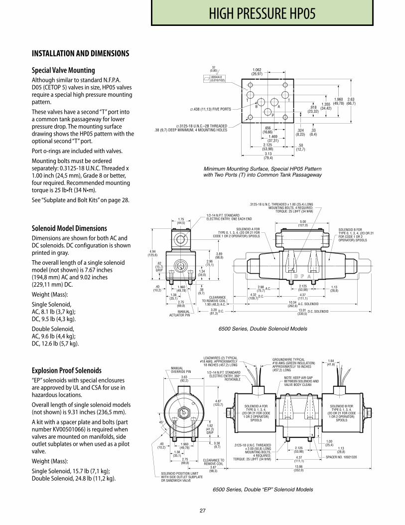
PF3000 SERIES, 10 DESIGNHIGH PRESSURE HP05
27
INSTALLATION AND DIMENSIONS
Special Valve MountingAlthough similar to standard N.F.P.A. D05 (CETOP 5) valves in size, HP05 valves require a special high pressure mounting pattern.
These valves have a second “T” port into a common tank passageway for lower pressure drop. The mounting surface drawing shows the HP05 pattern with the optional second “T” port.
Port o-rings are included with valves.
Mounting bolts must be ordered separately: 0.3125-18 U.N.C. Threaded x 1.00 inch (24,5 mm), Grade 8 or better, four required. Recommended mounting torque is 25 lb•ft (34 N•m).
See “Subplate and Bolt Kits” on page 28.
Solenoid Model DimensionsDimensions are shown for both AC and DC solenoids. DC configuration is shown printed in gray.
The overall length of a single solenoid model (not shown) is 7.67 inches (194,8 mm) AC and 9.02 inches (229,11 mm) DC.
Weight (Mass):
Single Solenoid, AC, 8.1 lb (3,7 kg); DC, 9.5 lb (4,3 kg).
Double Solenoid, AC, 9.6 lb (4,4 kg); DC, 12.6 lb (5,7 kg).
Explosion Proof Solenoids“EP” solenoids with special enclosures are approved by UL and CSA for use in hazardous locations.
Overall length of single solenoid models (not shown) is 9.31 inches (236,5 mm).
A kit with a spacer plate and bolts (part number KV00501066) is required when valves are mounted on manifolds, side outlet subplates or when used as a pilot valve.
Weight (Mass):
Single Solenoid, 15.7 lb (7,1 kg); Double Solenoid, 24.8 lb (11,2 kg).
1.13(28,8)
2.125(53,98)
4.37(111,1)
2.98(75,7)
4.32(109,7)
3.20(81,3)
CLEARANCETO REMOVE COIL
1.90 (48,3) A.C. 10.34(262,6)
13.01(330,5)
5.00(127,0)
1/2-14 N.P.T. STANDARDELECTRIC ENTRY, ONE EACH END
2.96(75,1)
.38(9,7)
.62(15,7)GRIP 1.34
(34,0)
3.89(98,8)
.3125-18 U.N.C. THREADED x 1.00 (25,4) LONGMOUNTING BOLTS, 4 REQUIRED;
TORQUE: 25 LB•FT (34 N•M)
MANUALACTUATOR PIN
4.94(125,6)
D.C.
A.C.
D.C.
A.C. SOLENOID
1.75(44,5)
2.75(69,8)
1.38(35,1)
D.C. SOLENOID
SOLENOID A FORTYPE 0, 1, 3, 4, (2O OR 21 FOR
CODE 1 OR 2 OPERATOR) SPOOLS
SOLENOID B FORTYPE 0, 1, 3, 4, (2O OR 21FOR CODE 1 OR 2OPERATOR) SPOOLS
1.960(49,78)
.40(10,2)
2.63(66,7)
3.13(79,4)
.324(8,23)
.918(23,32)
1.355(34,42)
P
T
∅.438 (11,13) FIVE PORTS
∅.3125-18 U.N.C.–2B THREADED.38 (9,7) DEEP MINIMUM, 4 MOUNTING HOLES .33
(8,4)
1.960(49,78)
AB
2.125(53,98)
1.469(37,31)
.656(16,66)
.50(12,7)
1.062(26,97)
T
.0004/4.0(0,010/102)
32(0,80)
13.86(352,0)
45°
0.38(9,7)
1.00(25,4)
1.62(41,2)GRIP
4.87(123,7)
SOLENOID POSITION LIMITWITH SIDE OUTLET SUBPLATEOR SANDWICH VALVE
MANUALOVERRIDE PIN 1/2–14 N.P.T. STANDARD
ELECTRIC ENTRY, 360°ROTATABLE NOTE: KEEP AIR GAP
BETWEEN SOLENOID ANDVALVE BODY CLEAN
GROUNDWIRE TYPICAL#18 AWG (GREEN INSULATION)APPROXIMATELY 18 INCHES(457,2) LONG
LEADWIRES (2) TYPICAL#18 AWG, APPROXIMATELY
18 INCHES (457,2) LONG
3.63(92,2)
1.64(41,6)
3.87(98,3)
CLEARANCE TOREMOVE COIL
SPACER NO. 10921320
2.125(53,98)
4.37(111,1)
1.13(28,8)
.3125-18 U.N.C. THREADEDx 2.00 (50,8) LONGMOUNTING BOLTS,
4 REQUIRED;TORQUE: 25 LB•FT (34 N•M)
SOLENOID A FORTYPE 0, 1, 3, 4,
(2O OR 21 FOR CODE1 OR 2 OPERATOR)
SPOOLS
SOLENOID B FORTYPE 0, 1, 3, 4,
(2O OR 21 FOR CODE1 OR 2 OPERATOR)
SPOOLS
2.75(69,8)
1.38(35,1)
1.960(49,78)
.40(10,2)
6500 Series, Double Solenoid Models
6500 Series, Double “EP” Solenoid Models
Minimum Mounting Surface, Special HP05 Pattern with Two Ports (T) into Common Tank Passageway
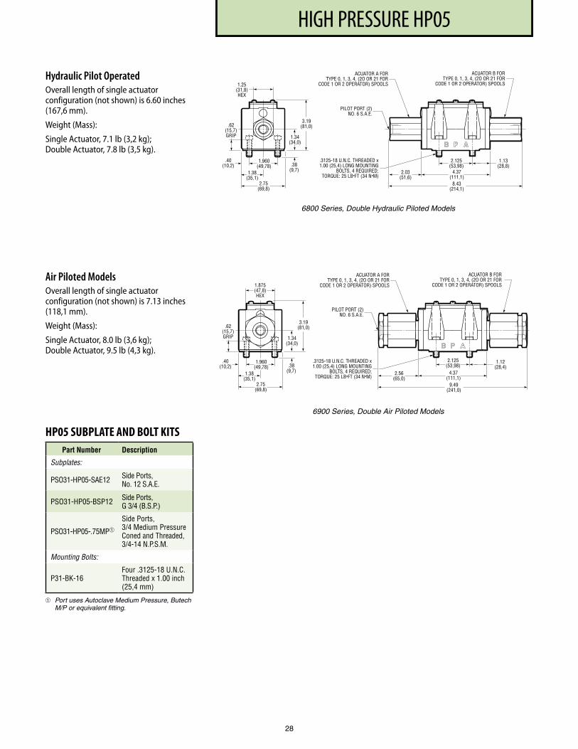
PF3000 SERIES, 10 DESIGNHIGH PRESSURE HP05
28
Hydraulic Pilot OperatedOverall length of single actuator configuration (not shown) is 6.60 inches (167,6 mm).
Weight (Mass):
Single Actuator, 7.1 lb (3,2 kg); Double Actuator, 7.8 lb (3,5 kg).
Air Piloted ModelsOverall length of single actuator configuration (not shown) is 7.13 inches (118,1 mm).
Weight (Mass):
Single Actuator, 8.0 lb (3,6 kg); Double Actuator, 9.5 lb (4,3 kg).
ACUATOR A FORTYPE 0, 1, 3, 4, (2O OR 21 FOR
CODE 1 OR 2 OPERATOR) SPOOLS
1.12(28,4)
2.125(53,98)
4.37(111,1)
2.56(65,0)
9.49(241,0)
3.19(81,0)
.38(9,7)
.62(15,7)GRIP 1.34
(34,0)
.3125-18 U.N.C. THREADED x1.00 (25,4) LONG MOUNTING
BOLTS, 4 REQUIRED;TORQUE: 25 LB•FT (34 N•M)
2.75(69,8)
1.875(47,8)HEX
ACUATOR B FORTYPE 0, 1, 3, 4, (2O OR 21 FOR
CODE 1 OR 2 OPERATOR) SPOOLS
PILOT PORT (2)NO. 6 S.A.E.
1.38(35,1)
1.960(49,78)
.40(10,2)
6900 Series, Double Air Piloted Models
1.13(28,8)
2.125(53,98)
4.37(111,1)
2.03(51,6)
8.43(214,1)
3.19(81,0).62
(15,7)GRIP 1.34
(34,0)
1.25(31,8)HEX
ACUATOR A FORTYPE 0, 1, 3, 4, (2O OR 21 FOR
CODE 1 OR 2 OPERATOR) SPOOLS
ACUATOR B FORTYPE 0, 1, 3, 4, (2O OR 21 FOR
CODE 1 OR 2 OPERATOR) SPOOLS
PILOT PORT (2)NO. 6 S.A.E.
.3125-18 U.N.C. THREADED x1.00 (25,4) LONG MOUNTING
BOLTS, 4 REQUIRED;TORQUE: 25 LB•FT (34 N•M)
.38(9,7)
2.75(69,8)
1.38(35,1)
1.960(49,78)
.40(10,2)
6800 Series, Double Hydraulic Piloted Models
HP05 SUBPLATE AND BOLT KITSPart Number Description
Subplates:
PSO31-HP05-SAE12 Side Ports, No . 12 S .A .E .
PSO31-HP05-BSP12 Side Ports, G 3/4 (B .S .P .)
PSO31-HP05- .75MP
Side Ports, 3/4 Medium Pressure Coned and Threaded, 3/4-14 N .P .S .M .
Mounting Bolts:
P31-BK-16Four .3125-18 U .N .C . Threaded x 1 .00 inch (25,4 mm)
Port uses Autoclave Medium Pressure, Butech M/P or equivalent fitting.
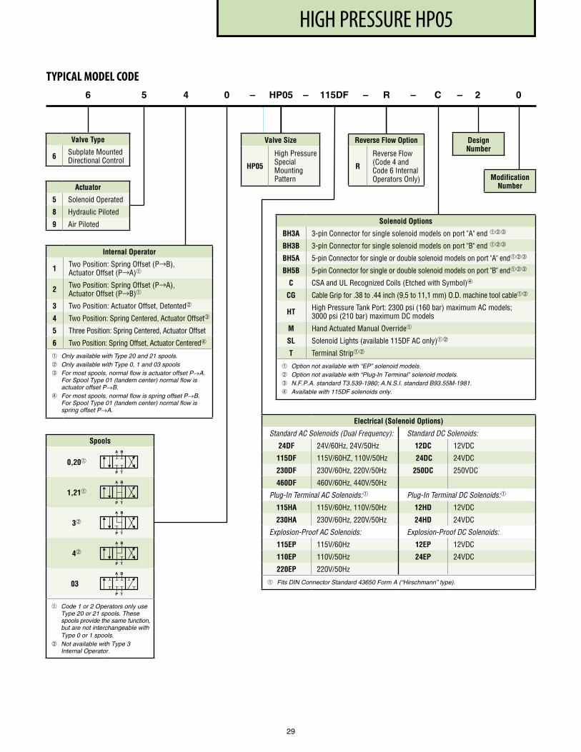
PF3000 SERIES, 10 DESIGNHIGH PRESSURE HP05
29
Actuator
5 Solenoid Operated
8 Hydraulic Piloted
9 Air Piloted
6 5 4 0 – HP05 – 115DF – R – C – 2 0
Valve Type
6 Subplate Mounted Directional Control
TYPICAL MODEL CODE
Spools
0,20
1,21
3
4
03
Code 1 or 2 Operators only use Type 20 or 21 spools. These spools provide the same function, but are not interchangeable with Type 0 or 1 spools.
Not available with Type 3 Internal Operator.
Electrical (Solenoid Options)
Standard AC Solenoids (Dual Frequency): Standard DC Solenoids:
24DF 24V/60Hz, 24V/50Hz 12DC 12VDC
115DF 115V/60HZ, 110V/50Hz 24DC 24VDC
230DF 230V/60Hz, 220V/50Hz 250DC 250VDC
460DF 460V/60Hz, 440V/50Hz
Plug-In Terminal AC Solenoids: Plug-In Terminal DC Solenoids:
115HA 115V/60Hz, 110V/50Hz 12HD 12VDC
230HA 230V/60Hz, 220V/50Hz 24HD 24VDC
Explosion-Proof AC Solenoids: Explosion-Proof DC Solenoids:
115EP 115V/60Hz 12EP 12VDC
110EP 110V/50Hz 24EP 24VDC
220EP 220V/50Hz
Fits DIN Connector Standard 43650 Form A (“Hirschmann” type).
Reverse Flow Option
R
Reverse Flow (Code 4 and Code 6 Internal Operators Only)
A B
P T
A B
P T
A B
P T
A B
P T
A B
P T
Valve Size
HP05
High Pressure Special Mounting Pattern
Design Number
Modification Number
Internal Operator
1 Two Position: Spring Offset (P→B), Actuator Offset (P→A)
2 Two Position: Spring Offset (P→A), Actuator Offset (P→B)
3 Two Position: Actuator Offset, Detented
4 Two Position: Spring Centered, Actuator Offset➂
5 Three Position: Spring Centered, Actuator Offset
6 Two Position: Spring Offset, Actuator Centered➃
Only available with Type 20 and 21 spools. Only available with Type 0, 1 and 03 spools➂ For most spools, normal flow is actuator offset P→A.
For Spool Type 01 (tandem center) normal flow is actuator offset P→B.
➃ For most spools, normal flow is spring offset P→B. For Spool Type 01 (tandem center) normal flow is spring offset P→A.
A B
P T
A B
P T
A B
P T
A B
P T
A B
P T
A B
P T
Solenoid Options
BH3A 3-pin Connector for single solenoid models on port "A" end ➂
BH3B 3-pin Connector for single solenoid models on port "B" end ➂
BH5A 5-pin Connector for single or double solenoid models on port "A" end➂
BH5B 5-pin Connector for single or double solenoid models on port "B" end➂
C CSA and UL Recognized Coils (Etched with Symbol)➃
CG Cable Grip for .38 to .44 inch (9,5 to 11,1 mm) O .D . machine tool cable
HT High Pressure Tank Port: 2300 psi (160 bar) maximum AC models; 3000 psi (210 bar) maximum DC models
M Hand Actuated Manual Override
SL Solenoid Lights (available 115DF AC only)
T Terminal Strip
Option not available with “EP” solenoid models. Option not available with “Plug-In Terminal” solenoid models. ➂ N.F.P.A. standard T3.539-1980; A.N.S.I. standard B93.55M-1981. ➃ Available with 115DF solenoids only.
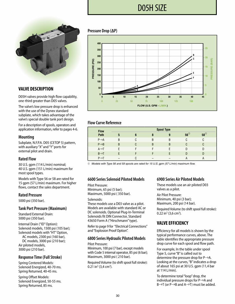
PF3000 SERIES, 10 DESIGND05H SIZE
30
VALVE DESCRIPTIOND05H valves provide high flow capability, one-third greater than D05 valves.
The valve’s low pressure drop is enhanced with the use of the Dynex standard subplate, which takes advantage of the valve’s special double tank port design.
For a description of spools, operators and application information, refer to pages 4-6.
MountingSubplate, N.F.P.A. D05 (CETOP 5) pattern, with auxiliary “X” and “Y” ports for external pilot and drain.
Rated Flow30 U.S. gpm (114 L/min) nominal; 40 U.S. gpm (151 L/min) maximum for most spool types.
Models with Type 56 or 58 are rated for 15 gpm (57 L/min) maximum. For higher flows, contact the sales department.
Rated Pressure5000 psi (350 bar).
Tank Port Pressure (Maximum)Standard External Drain: 5000 psi (350 bar).
Internal Drain (“ID” Option): Solenoid models, 1500 psi (105 bar); Solenoid models with “HT” Option, AC models, 2300 psi (160 bar), DC models, 3000 psi (210 bar); Air piloted models, 3000 psi (210 bar).
Response Time (Full Stroke)Spring Centered Models: Solenoid Energized, 40-70 ms. Spring Returned, 40-45 ms.
Spring Offset Models: Solenoid Energized, 50-55 ms. Spring Returned, 85 ms.
6600 Series Solenoid Piloted ModelsPilot Pressure: Minimum, 65 psi (5 bar); Maximum, 5000 psi ( 350 bar).
Solenoids: These models use a D03 valve as a pilot. Models are available with standard AC or DC solenoids. Optional Plug-In-Terminal Solenoids fit DIN Connector, Standard 43650 Form A (“Hirschmann” type).
Refer to page 9 for “Electrical Connections” and “Explosion Proof Option”.
6800 Series Hydraulic Piloted ModelsPilot Pressure: Minimum, 100 psi (7 bar), except models with Code 5 internal operator, 85 psi (6 bar); Maximum, 3000 psi ( 210 bar).
Required Volume (to shift spool full stroke): 0.21 in3 (3,4 cm3).
6900 Series Air Piloted ModelsThese models use an air piloted D03 valves as a pilot.
Air Pilot Pressure: Minimum, 40 psi (3 bar); Maximum, 200 psi (14 bar).
Required Volume (to shift spool full stroke): 0.22 in3 (3,6 cm3).
VALVE EFFICIENCYEfficiency for all models is shown by the typical performance curves, above. The table identifies the appropriate pressure drop curve for each spool and flow path.
For example, In the table under spool Type 5, curve “B” is called out to determine the pressure drop for P→A. Looking at the curves, “B” indicates a drop of about 165 psi at 30 U.S. gpm (11,4 bar at 114 L/min).
To determine total “loop” drop, the individual pressure drops for P→A and B→T (or P→B and A→T) must be added.
Pressure Drop (∆P)
Flow Curve Reference
Flow Path
Spool Type
5 6 8 9 56 58
P→A B C B B C C P→B B C B B C C A→T E F F E D D B→T E F F E D D P→T – C – – A A
Models with Type 56 and 59 spools are rated for 15 U.S. gpm (57 L/min) maximum flow.
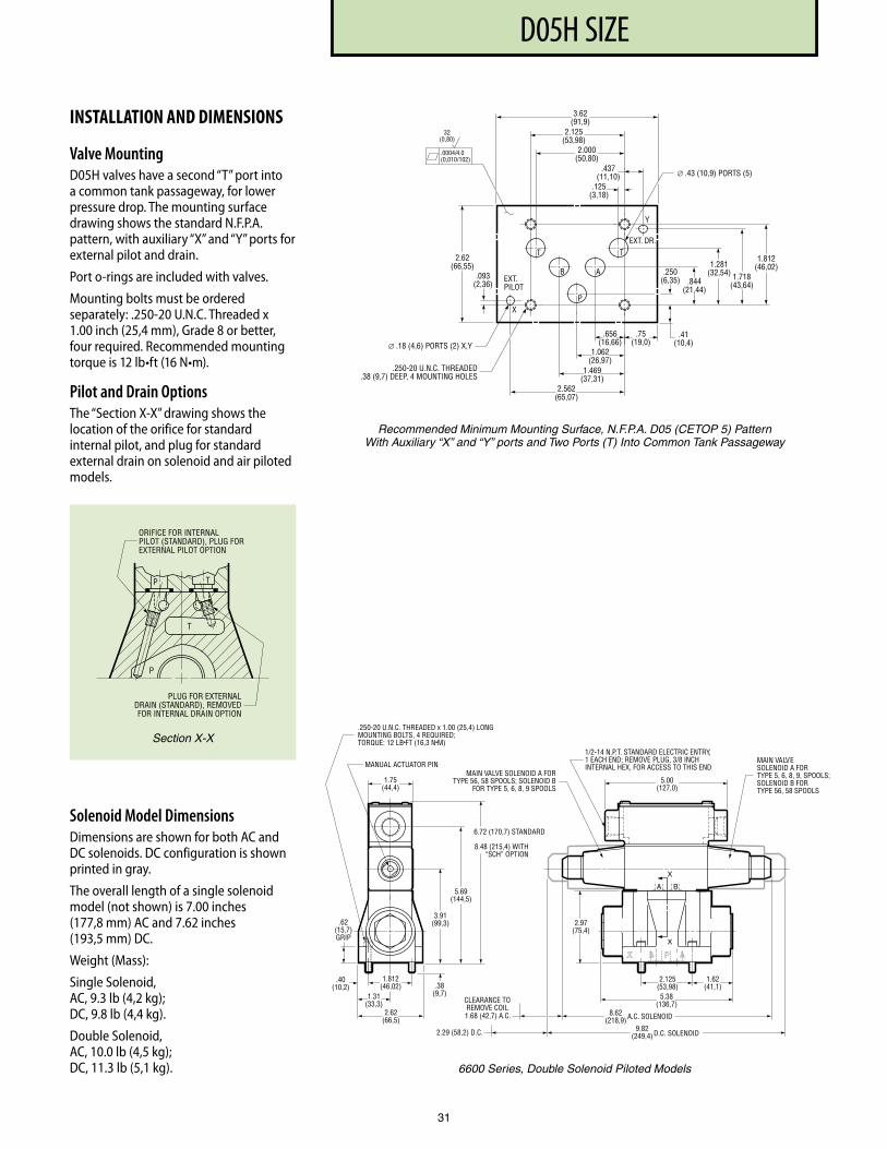
PF3000 SERIES, 10 DESIGND05H SIZE
31
INSTALLATION AND DIMENSIONS
Valve MountingD05H valves have a second “T” port into a common tank passageway, for lower pressure drop. The mounting surface drawing shows the standard N.F.P.A. pattern, with auxiliary “X” and “Y” ports for external pilot and drain.
Port o-rings are included with valves.
Mounting bolts must be ordered separately: .250-20 U.N.C. Threaded x 1.00 inch (25,4 mm), Grade 8 or better, four required. Recommended mounting torque is 12 lb•ft (16 N•m).
Pilot and Drain OptionsThe “Section X-X” drawing shows the location of the orifice for standard internal pilot, and plug for standard external drain on solenoid and air piloted models.
∅ .18 (4,6) PORTS (2) X,Y
EXT.PILOT
EXT. DR.
.656(16,66)
1.062(26,97)
1.469(37,31)
2.562(65,07)
.75(19,0)
.41(10,4)
1.718(43,64)
.250(6,35)
1.812(46,02)
.437(11,10)
.125(3,18)
2.125(53,98)
2.000(50,80)
3.62(91,9)
1.281(32,54)
.844(21,44)
.093(2,36)
2.62(66,55)
.0004/4.0(0,010/102)
32(0,80)
∅ .43 (10,9) PORTS (5)
.250-20 U.N.C. THREADED.38 (9,7) DEEP, 4 MOUNTING HOLES
X
Y
T
B
P
A
T
Recommended Minimum Mounting Surface, N.F.P.A. D05 (CETOP 5) Pattern With Auxiliary “X” and “Y” ports and Two Ports (T) Into Common Tank Passageway
6600 Series, Double Solenoid Piloted Models
.250-20 U.N.C. THREADED x 1.00 (25,4) LONGMOUNTING BOLTS, 4 REQUIRED;TORQUE: 12 LB•FT (16,3 N•M)
.62(15,7)GRIP
1.812(46,02) .38
(9,7)
2.97(75,4)
2.125(53,98)5.38
(136,7)
1.62(41,1)
1.31(33,3)
2.62(66,5)
3.91(99,3)
5.69(144,5)
X
.40(10,2)
BA
A.C. SOLENOID
D.C. SOLENOID2.29 (58,2) D.C.
1.68 (42,7) A.C.
MAIN VALVE SOLENOID A FORTYPE 56, 58 SPOOLS; SOLENOID B
FOR TYPE 5, 6, 8, 9 SPOOLS
1/2-14 N.P.T. STANDARD ELECTRIC ENTRY,1 EACH END; REMOVE PLUG, 3/8 INCHINTERNAL HEX, FOR ACCESS TO THIS END
5.00(127,0)
9.82(249,4)
MANUAL ACTUATOR PIN
1.75(44,4)
6.72 (170,7) STANDARD
8.48 (215,4) WITH“SCH” OPTION
MAIN VALVESOLENOID A FORTYPE 5, 6, 8, 9, SPOOLS;SOLENOID B FORTYPE 56, 58 SPOOLS
8.62(218,9)
CLEARANCE TOREMOVE COIL
X
TP
P
T
ORIFICE FOR INTERNALPILOT (STANDARD), PLUG FOREXTERNAL PILOT OPTION
PLUG FOR EXTERNALDRAIN (STANDARD), REMOVEDFOR INTERNAL DRAIN OPTION
Section X-X
Solenoid Model DimensionsDimensions are shown for both AC and DC solenoids. DC configuration is shown printed in gray.
The overall length of a single solenoid model (not shown) is 7.00 inches (177,8 mm) AC and 7.62 inches (193,5 mm) DC.
Weight (Mass):
Single Solenoid, AC, 9.3 lb (4,2 kg); DC, 9.8 lb (4,4 kg).
Double Solenoid, AC, 10.0 lb (4,5 kg); DC, 11.3 lb (5,1 kg).
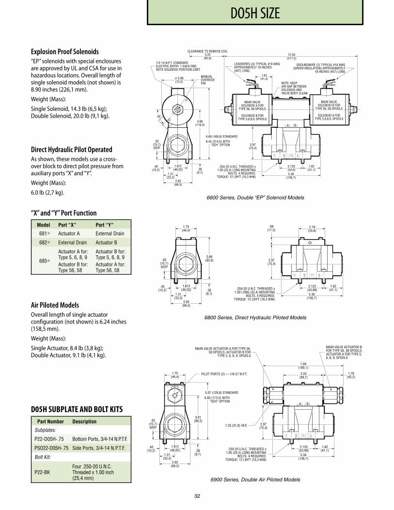
PF3000 SERIES, 10 DESIGNDO5H SIZE
32
MANUALOVERRIDEPIN
12.50(317,5)
.250-20 U.N.C. THREADED x1.00 (25,4) LONG MOUNTING
BOLTS, 4 REQUIRED;TORQUE: 12 LB•FT (16,3 N•M)
1/2-14 N.P.T. STANDARDELECTRIC ENTRY, 1 EACH END;NOTE SOLENOID POSITION LIMIT
.62(15,7)GRIP
2.97(75,4)
2.125(54,0)5.38
(136,7)
1.62(41,1)
4.66(118,4)
1.812(46,02) .38
(9,7)1.31(33,3)
2.62(66,5)
.40(10,2)
6.69 (169,9) STANDARD8.45 (214,6) WITH
“SCH” OPTION
BA
∅ 2.88(73.2)
45˚
1.63(41,4)
CLEARANCE TO REMOVE COIL3.25
(82,6)
LEADWIRES (4) TYPICAL #18 AWGAPPROXIMATELY 18 INCHES(457) LONG
GROUNDWIRE (2) TYPICAL #18 AWG(GREEN INSULATION) APPROXIMATELY
18 INCHES (457) LONG
NOTE: KEEPAIR GAP BETWEENSOLENOID ANDVALVE BODY CLEAN
MAIN VALVESOLENOID B FOR
TYPE 56, 58 SPOOLS
SOLENOID A FORTYPE 5,6,8,9, SPOOLS
MAIN VALVESOLENOID A FOR
TYPE 56, 58 SPOOLS
SOLENOID B FORTYPE 5,6,8,9, SPOOLS
.250-20 U.N.C. THREADED x1.00 LONG (25,4) MOUNTING
BOLTS, 4 REQUIRED;TORQUE: 12 LB•FT (16,3 N•M)
.62(15,7)GRIP
1.812(46,02) .38
(9,7)
2.97(75,4)
2.125(53,98)5.38
(136,7)
1.62(41,1)
1.31(33,3)
2.62(66,5)
3.66(93,0)
.69(17,5)
.40(10,2)
1.75(44,4)
2.19(55,6)
.250-20 U.N.C. THREADED x1.00 (25,4) LONG MOUNTING
BOLTS, 4 REQUIRED;TORQUE: 12 LB•FT (16,3 N•M)
.62(15,7)GRIP
2.97(75,4)
2.125(53,98)5.38
(136,7)
1.62(41,1)
3.91(99,3)
1.812(46,02) .38
(9,7)1.31(33,3)
2.62(66,5)
.40(10,2)
5.07 (128,8) STANDARD6.83 (173,5) WITH
“SCH” OPTION
PILOT PORTS (2) — 1/8-27 N.P.T.
BA
1.75(44,4)
7.09(180,1)
3.53(89,7)
1.78(45,2)
1.25 (31,8) HEX
MAIN VALVE ACTUATOR A FOR TYPE 56,58 SPOOLS; ACTUATOR B FOR
TYPE 5, 6, 8, 9, SPOOLS
MAIN VALVE ACTUATOR BFOR TYPE 56, 58 SPOOLS;ACTUATOR A FOR TYPE 5,6, 8, 9, SPOOLS
6600 Series, Double “EP” Solenoid Models
6800 Series, Direct Hydraulic Piloted Models
6900 Series, Double Air Piloted Models
Explosion Proof Solenoids“EP” solenoids with special enclosures are approved by UL and CSA for use in hazardous locations. Overall length of single solenoid models (not shown) is 8.90 inches (226,1 mm).
Weight (Mass):
Single Solenoid, 14.3 lb (6,5 kg); Double Solenoid, 20.0 lb (9,1 kg).
Direct Hydraulic Pilot OperatedAs shown, these models use a cross-over block to direct pilot pressure from auxiliary ports “X” and “Y”.
Weight (Mass):
6.0 lb (2,7 kg).
“X” and “Y” Port Function Model Port “X” Port “Y”
681✳ Actuator A External Drain
682✳ External Drain Actuator B
685✳
Actuator A for: Type 5, 6, 8, 9Actuator B for: Type 56, 58
Actuator B for: Type 5, 6, 8, 9Actuator A for: Type 56, 58
Air Piloted ModelsOverall length of single actuator configuration (not shown) is 6.24 inches (158,5 mm).
Weight (Mass):
Single Actuator, 8.4 lb (3,8 kg); Double Actuator, 9.1 lb (4,1 kg).
D05H SUBPLATE AND BOLT KITSPart Number Description
Subplates:
P22-D05H- .75 Bottom Ports, 3/4-14 N .P .T .F .
PSO22-D05H- .75 Side Ports, 3/4-14 N .P .T .F .
Bolt Kit:
P22-BKFour .250-20 U .N .C . Threaded x 1 .00 inch (25,4 mm)
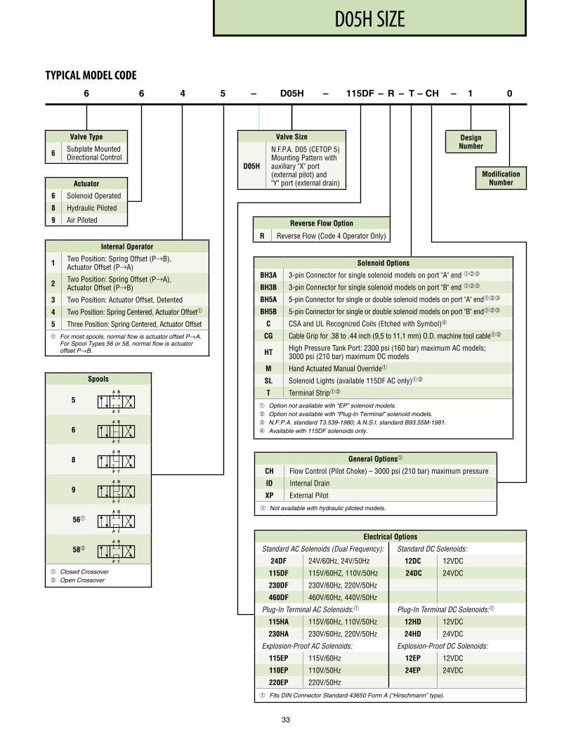
PF3000 SERIES, 10 DESIGND05H SIZE
33
Actuator
6 Solenoid Operated
8 Hydraulic Piloted
9 Air Piloted
6 6 4 5 – D05H – 115DF – R – T – CH – 1 0
Valve Type
6 Subplate Mounted Directional Control
Design Number
Modification Number
TYPICAL MODEL CODE
Valve Size
D05H
N .F .P .A . D05 (CETOP 5) Mounting Pattern with auxiliary "X" port (external pilot) and "Y" port (external drain)
Internal Operator
1 Two Position: Spring Offset (P→B), Actuator Offset (P→A)
2 Two Position: Spring Offset (P→A), Actuator Offset (P→B)
3 Two Position: Actuator Offset, Detented
4 Two Position: Spring Centered, Actuator Offset
5 Three Position: Spring Centered, Actuator Offset
For most spools, normal flow is actuator offset P→A. For Spool Types 56 or 58, normal flow is actuator offset P→B.
Spools
5
6
8
9
56
58
Closed Crossover Open Crossover
A B
P T
A B
P T
A B
P T
A B
P T
A B
P T
A B
P T
Solenoid Options
BH3A 3-pin Connector for single solenoid models on port "A" end ➂
BH3B 3-pin Connector for single solenoid models on port "B" end ➂
BH5A 5-pin Connector for single or double solenoid models on port "A" end➂
BH5B 5-pin Connector for single or double solenoid models on port "B" end➂
C CSA and UL Recognized Coils (Etched with Symbol)➃
CG Cable Grip for .38 to .44 inch (9,5 to 11,1 mm) O .D . machine tool cable
HT High Pressure Tank Port: 2300 psi (160 bar) maximum AC models; 3000 psi (210 bar) maximum DC models
M Hand Actuated Manual Override
SL Solenoid Lights (available 115DF AC only)
T Terminal Strip
Option not available with “EP” solenoid models. Option not available with “Plug-In Terminal” solenoid models. ➂ N.F.P.A. standard T3.539-1980; A.N.S.I. standard B93.55M-1981. ➃ Available with 115DF solenoids only.
Electrical Options
Standard AC Solenoids (Dual Frequency): Standard DC Solenoids:
24DF 24V/60Hz, 24V/50Hz 12DC 12VDC
115DF 115V/60HZ, 110V/50Hz 24DC 24VDC
230DF 230V/60Hz, 220V/50Hz
460DF 460V/60Hz, 440V/50Hz
Plug-In Terminal AC Solenoids: Plug-In Terminal DC Solenoids:
115HA 115V/60Hz, 110V/50Hz 12HD 12VDC
230HA 230V/60Hz, 220V/50Hz 24HD 24VDC
Explosion-Proof AC Solenoids: Explosion-Proof DC Solenoids:
115EP 115V/60Hz 12EP 12VDC
110EP 110V/50Hz 24EP 24VDC
220EP 220V/50Hz
Fits DIN Connector Standard 43650 Form A (“Hirschmann” type).
Reverse Flow Option
R Reverse Flow (Code 4 Operator Only)
General Options
CH Flow Control (Pilot Choke) – 3000 psi (210 bar) maximum pressure
ID Internal Drain
XP External Pilot
Not available with hydraulic piloted models.
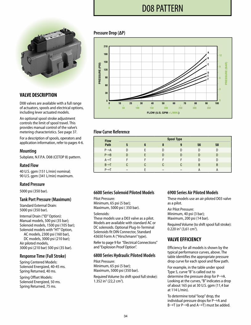
PF3000 SERIES, 10 DESIGND08 PATTERN
34
VALVE DESCRIPTIOND08 valves are available with a full range of actuators, spools and electrical options, including lever actuated models.
An optional spool stroke adjustment controls the limit of spool travel. This provides manual control of the valve’s metering characteristics. See page 37.
For a description of spools, operators and application information, refer to pages 4-6.
MountingSubplate, N.F.P.A. D08 (CETOP 8) pattern.
Rated Flow40 U.S. gpm (151 L/min) nominal; 90 U.S. gpm (341 L/min) maximum.
Rated Pressure5000 psi (350 bar).
Tank Port Pressure (Maximum)Standard External Drain: 5000 psi (350 bar).
Internal Drain (“ID” Option): Manual models, 500 psi (35 bar); Solenoid models, 1500 psi (105 bar); Solenoid models with “HT” Option, AC models, 2300 psi (160 bar), DC models, 3000 psi (210 bar); Air piloted models, 3000 psi (210 bar) 500 psi (35 bar).
Response Time (Full Stroke)Spring Centered Models: Solenoid Energized, 40-45 ms. Spring Returned, 40 ms.
Spring Offset Models: Solenoid Energized, 50 ms. Spring Returned, 75 ms.
6600 Series Solenoid Piloted ModelsPilot Pressure: Minimum, 65 psi (5 bar); Maximum, 5000 psi ( 350 bar).
Solenoids: These models use a D03 valve as a pilot. Models are available with standard AC or DC solenoids. Optional Plug-In-Terminal Solenoids fit DIN Connector, Standard 43650 Form A (“Hirschmann” type).
Refer to page 9 for “Electrical Connections” and “Explosion Proof Option”.
6800 Series Hydraulic Piloted ModelsPilot Pressure: Minimum, 65 psi (5 bar); Maximum, 5000 psi (350 bar).
Required Volume (to shift spool full stroke): 1.352 in3 (22,2 cm3).
6900 Series Air Piloted ModelsThese models use an air piloted D03 valve as a pilot.
Air Pilot Pressure: Minimum, 40 psi (3 bar); Maximum, 200 psi (14 bar).
Required Volume (to shift spool full stroke): 0.220 in3 (3,61 cm3).
VALVE EFFICIENCYEfficiency for all models is shown by the typical performance curves, above. The table identifies the appropriate pressure drop curve for each spool and flow path.
For example, in the table under spool Type 5, curve “B” is called out to determine the pressure drop for P→A. Looking at the curves, “B” indicates a drop of about 165 psi at 30 U.S. gpm (11,4 bar at 114 L/min).
To determine total “loop” drop, the individual pressure drops for P→A and B→T (or P→B and A→T) must be added.
Flow Curve Reference
Flow Path
Spool Type
5 6 8 9 56 58
P→A D E D D D D P→B D E D D D D A→T F F F F D D B→T C C C C B B P→T – E – – A A
Pressure Drop (∆P)
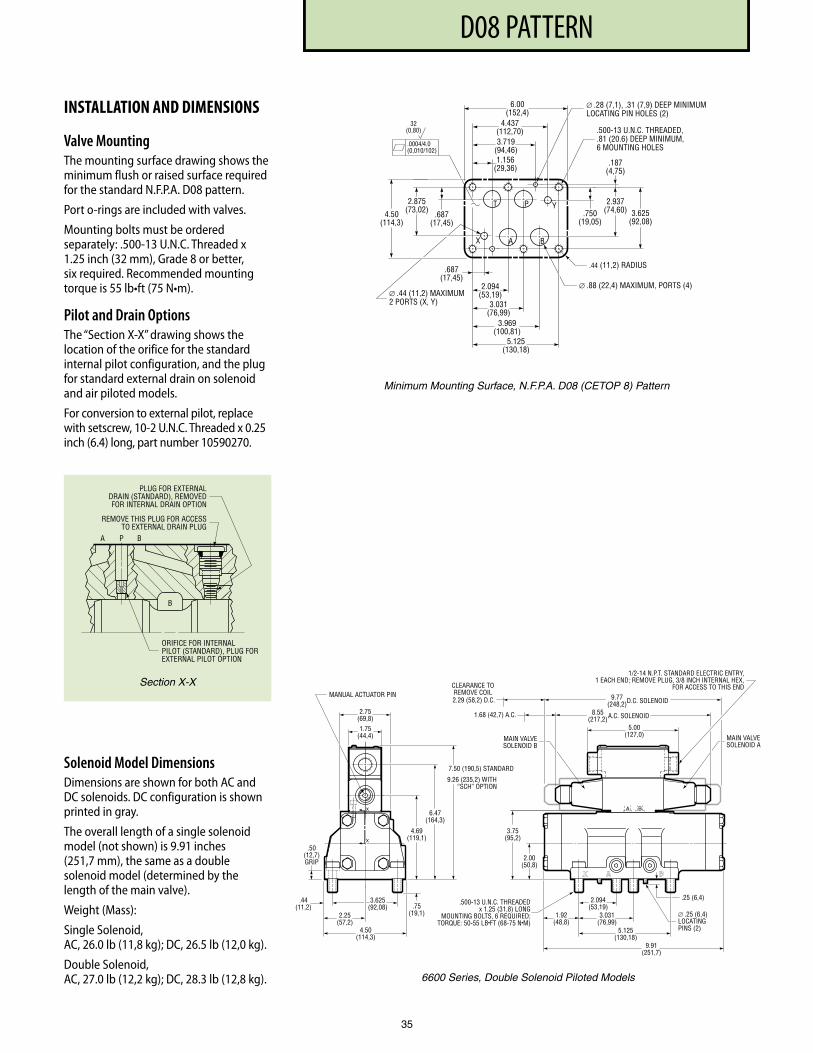
PF3000 SERIES, 10 DESIGND08 PATTERN
INSTALLATION AND DIMENSIONS
Valve MountingThe mounting surface drawing shows the minimum flush or raised surface required for the standard N.F.P.A. D08 pattern.
Port o-rings are included with valves.
Mounting bolts must be ordered separately: .500-13 U.N.C. Threaded x 1.25 inch (32 mm), Grade 8 or better, six required. Recommended mounting torque is 55 lb•ft (75 N•m).
Pilot and Drain OptionsThe “Section X-X” drawing shows the location of the orifice for the standard internal pilot configuration, and the plug for standard external drain on solenoid and air piloted models.
For conversion to external pilot, replace with setscrew, 10-2 U.N.C. Threaded x 0.25 inch (6.4) long, part number 10590270.
6.00 (152,4)
3.719 (94,46) 1.156
(29,36)
4.437 (112,70)
.750 (19,05)
2.937 (74,60)
.187 (4,75)
.687 (17,45)
3.969 (100,81)
2.094 (53,19)
A B
T P Y
X
∅ .88 (22,4) MAXIMUM, POR TS (4)
3.625 (92,08)
5.125 (130,18)
3.031 (76,99)
.687 (17,45)
2.875 (73,02) 4.50
(114,3)
.44 (11,2) RADIUS
.0004/ 4. 0 (0,010/102)
32 (0,80)
∅ .28 (7,1), .31 (7,9) DEEP MINIMUMLOCA TING PIN HOLES (2)
.500-13 U.N.C. THREADED,
.81 (20.6) DEEP MINIMUM, 6 MOUNTING HOLES
∅ .44 (11,2) MAXIMUM 2 POR TS (X, Y)
Minimum Mounting Surface, N.F.P.A. D08 (CETOP 8) Pattern
3.75 (95,2)
2.00 (50,8)
1.92 (48,8)
2.094 (53,19)
3.031 (76,99)
5.125 (130,18)
9.91 (251,7)
.25 (6,4)
2.75 (69,8)
MANUAL ACTUA TOR PIN
B A
A.C. SOLENOID
D.C. SOLENOID 2.29 (58,2) D.C.
1.68 (42,7) A.C.
MAIN VA LV E SOLENOID B
MAIN VA LV E SOLENOID A
1/2-14 N.P .T . ST ANDARD ELECTRIC ENTR Y, 1 EACH END; REMOVE PLUG, 3/8 INCH INTERNAL HEX,
FOR ACCESS TO THIS END
8.55 (217,2)
5.00 (127,0)
9.77 (248,2)
1.75 (44,4)
CLEARANCE TO REMOVE COIL
3.625 (92,08)
2.25 (57,2)
4.50 (114,3)
.44 (11,2)
.50 (12,7) GRIP
4.69 (119,1)
6.47 (164,3)
7.50 (190,5) ST ANDARD
9.26 (235,2) WITH “SCH” OPTION
.75 (19,1) ∅ .25 (6,4)
LOCA TING PINS (2)
.500-13 U.N.C. THREADEDx 1.25 (31,8) LONG
MOUNTING BOL TS, 6 REQUIRED; TORQUE: 50-55 LB • FT (68-75 N • M)
X
X
6600 Series, Double Solenoid Piloted Models
35
Section X-X
Solenoid Model DimensionsDimensions are shown for both AC and DC solenoids. DC configuration is shown printed in gray.
The overall length of a single solenoid model (not shown) is 9.91 inches (251,7 mm), the same as a double solenoid model (determined by the length of the main valve).
Weight (Mass):
Single Solenoid, AC, 26.0 lb (11,8 kg); DC, 26.5 lb (12,0 kg).
Double Solenoid, AC, 27.0 lb (12,2 kg); DC, 28.3 lb (12,8 kg).
PLUG FOR EXTERNALDRAIN (STANDARD), REMOVEDFOR INTERNAL DRAIN OPTION
REMOVE THIS PLUG FOR ACCESSTO EXTERNAL DRAIN PLUG
PA
B
B
ORIFICE FOR INTERNALPILOT (STANDARD), PLUG FOREXTERNAL PILOT OPTION
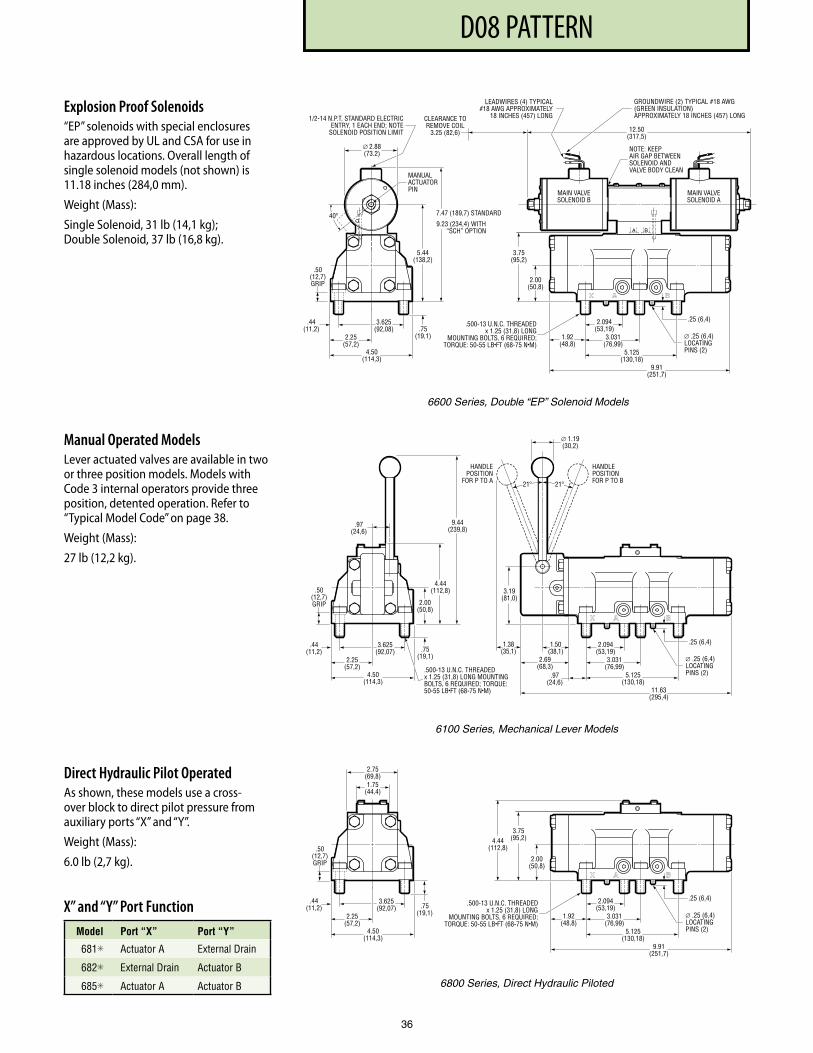
PF3000 SERIES, 10 DESIGND08 PATTERN
36
Explosion Proof Solenoids“EP” solenoids with special enclosures are approved by UL and CSA for use in hazardous locations. Overall length of single solenoid models (not shown) is 11.18 inches (284,0 mm).
Weight (Mass):
Single Solenoid, 31 lb (14,1 kg); Double Solenoid, 37 lb (16,8 kg).
Manual Operated Models Lever actuated valves are available in two or three position models. Models with Code 3 internal operators provide three position, detented operation. Refer to “Typical Model Code” on page 38.
Weight (Mass):
27 lb (12,2 kg).
Direct Hydraulic Pilot OperatedAs shown, these models use a cross-over block to direct pilot pressure from auxiliary ports “X” and “Y”.
Weight (Mass):
6.0 lb (2,7 kg).
X” and “Y” Port Function Model Port “X” Port “Y”
681✳ Actuator A External Drain
682✳ External Drain Actuator B
685✳ Actuator A Actuator B
3.75(95,2)
2.00(50,8)
1.92(48,8)
2.094(53,19)
3.031(76,99)
5.125(130,18)
9.91(251,7)
.25 (6,4)
∅ .25 (6,4)LOCATINGPINS (2)
.500-13 U.N.C. THREADEDx 1.25 (31,8) LONG
MOUNTING BOLTS, 6 REQUIRED;TORQUE: 50-55 LB•FT (68-75 N•M)
BA
MAIN VALVESOLENOID B
MAIN VALVESOLENOID A
CLEARANCE TOREMOVE COIL
3.25 (82,6) 12.50(317,5)
3.625(92,08)
2.25(57,2)
4.50(114,3)
.44(11,2) .75
(19,1)
.50(12,7)GRIP
5.44(138,2)
7.47 (189,7) STANDARD
9.23 (234,4) WITH“SCH” OPTION
40º
MANUALACTUATORPIN
NOTE: KEEPAIR GAP BETWEENSOLENOID ANDVALVE BODY CLEAN
GROUNDWIRE (2) TYPICAL #18 AWG(GREEN INSULATION)APPROXIMATELY 18 INCHES (457) LONG
LEADWIRES (4) TYPICAL#18 AWG APPROXIMATELY
18 INCHES (457) LONG1/2-14 N.P.T. STANDARD ELECTRICENTRY, 1 EACH END; NOTE
SOLENOID POSITION LIMIT
∅ 2.88(73.2)
6600 Series, Double “EP” Solenoid Models
2.094(53,19)
3.031(76,99)
5.125(130,18)
11.63(295,4)
.25 (6,4)
∅ .25 (6,4)LOCATINGPINS (2).500-13 U.N.C. THREADED
x 1.25 (31,8) LONG MOUNTINGBOLTS, 6 REQUIRED; TORQUE:50-55 LB•FT (68-75 N•M)
.97(24,6)
2.69(68,3)
1.50(38,1)
3.19(81,0)
1.38(35,1)
∅ 1.19(30,2)
3.625(92,07)
2.25(57,2)
4.50(114,3)
.44(11,2) .75
(19,1)
.50(12,7)GRIP
4.44(112,8)
9.44(239,8)
HANDLEPOSITION
FOR P TO A
HANDLEPOSITIONFOR P TO B
.97(24,6)
21º 21º
2.00(50,8)
6100 Series, Mechanical Lever Models
3.75(95,2)
2.00(50,8)
1.92(48,8)
2.094(53,19)
3.031(76,99)
5.125(130,18)
9.91(251,7)
.25 (6,4)
∅ .25 (6,4)LOCATINGPINS (2)
.500-13 U.N.C. THREADED x 1.25 (31,8) LONG
MOUNTING BOLTS, 6 REQUIRED;TORQUE: 50-55 LB•FT (68-75 N•M)
.50(12,7)GRIP
2.75(69,8)1.75
(44,4)
3.625(92,07)
2.25(57,2)
4.50(114,3)
.44(11,2) .75
(19,1)
4.44(112,8)
6800 Series, Direct Hydraulic Piloted
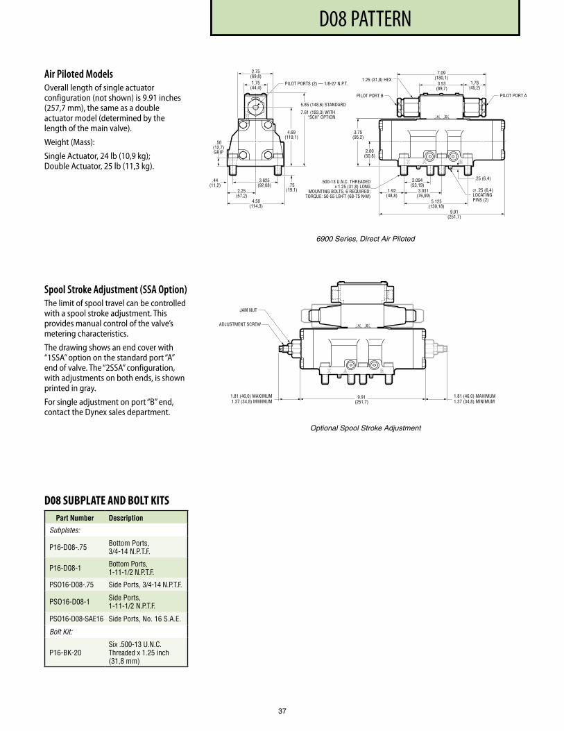
PF3000 SERIES, 10 DESIGND08 PATTERN
37
Air Piloted ModelsOverall length of single actuator configuration (not shown) is 9.91 inches (257,7 mm), the same as a double actuator model (determined by the length of the main valve).
Weight (Mass):
Single Actuator, 24 lb (10,9 kg); Double Actuator, 25 lb (11,3 kg).
Spool Stroke Adjustment (SSA Option)The limit of spool travel can be controlled with a spool stroke adjustment. This provides manual control of the valve’s metering characteristics.
The drawing shows an end cover with “1SSA” option on the standard port “A” end of valve. The “2SSA” configuration, with adjustments on both ends, is shown printed in gray.
For single adjustment on port “B” end, contact the Dynex sales department.
9.91(251,7)
1.81 (46,0) MAXIMUM1.37 (34,8) MINIMUM
JAM NUT
ADJUSTMENT SCREW
1.81 (46,0) MAXIMUM1.37 (34,8) MINIMUM
BA
Optional Spool Stroke Adjustment
3.75(95,2)
2.00(50,8)
1.92(48,8)
2.094(53,19)
3.031(76,99)
5.125(130,18)
9.91(251,7)
.25 (6,4)
∅ .25 (6,4)LOCATINGPINS (2)
.500-13 U.N.C. THREADEDx 1.25 (31,8) LONG
MOUNTING BOLTS, 6 REQUIRED;TORQUE: 50-55 LB•FT (68-75 N•M)
2.75(69,8)
PILOT PORTS (2) — 1/8-27 N.P.T.
BA
1.75(44,4)
PILOT PORT A
7.09(180,1)
3.53(89,7)
1.78(45,2)
PILOT PORT B
1.25 (31,8) HEX
3.625(92,08)
2.25(57,2)
4.50(114,3)
.44(11,2) .75
(19,1)
.50(12,7)GRIP
4.69(119,1)
5.85 (148,6) STANDARD
7.61 (193,3) WITH“SCH” OPTION
6900 Series, Direct Air Piloted
D08 SUBPLATE AND BOLT KITSPart Number Description
Subplates:
P16-D08- .75 Bottom Ports, 3/4-14 N .P .T .F .
P16-D08-1 Bottom Ports, 1-11-1/2 N .P .T .F .
PSO16-D08- .75 Side Ports, 3/4-14 N .P .T .F .
PSO16-D08-1 Side Ports, 1-11-1/2 N .P .T .F .
PSO16-D08-SAE16 Side Ports, No . 16 S .A .E .
Bolt Kit:
P16-BK-20Six .500-13 U .N .C . Threaded x 1 .25 inch (31,8 mm)
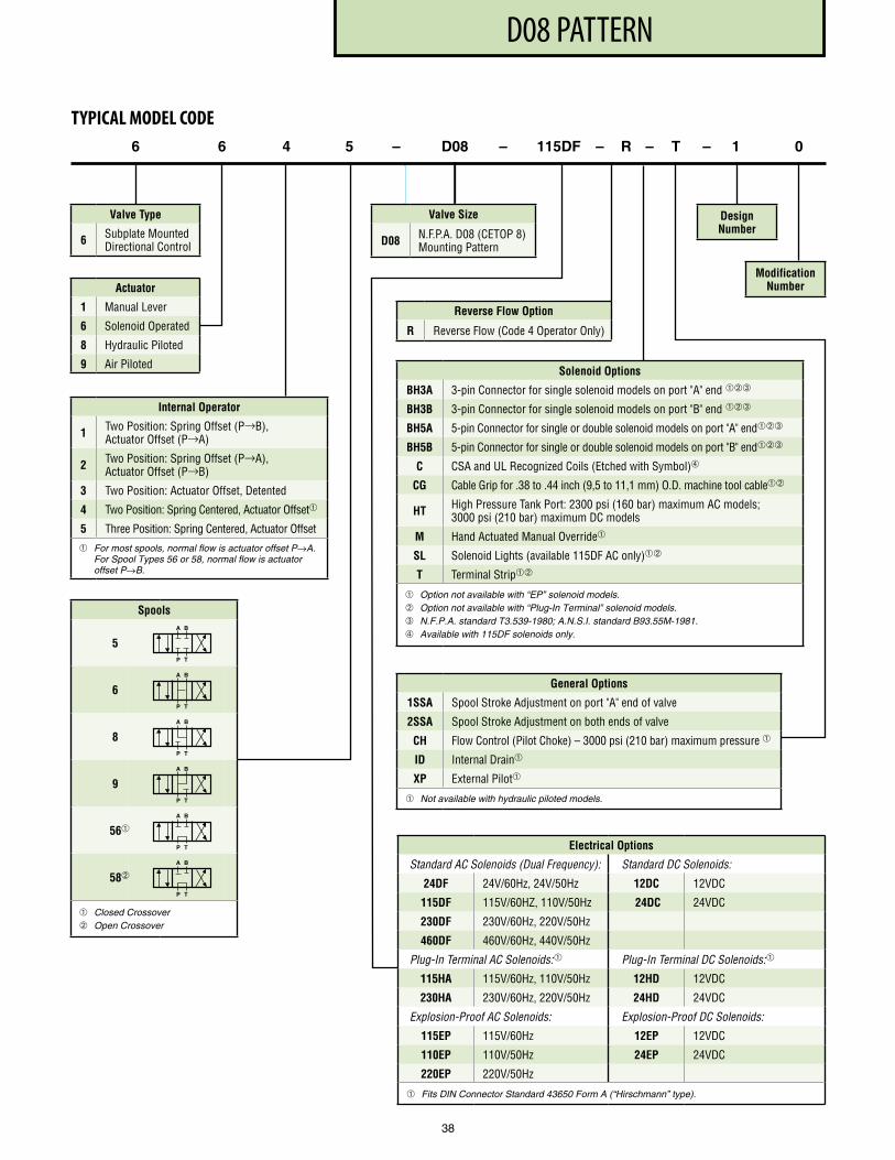
PF3000 SERIES, 10 DESIGND08 PATTERN
38
Actuator
1 Manual Lever
6 Solenoid Operated
8 Hydraulic Piloted
9 Air Piloted
6 6 4 5 – D08 – 115DF – R – T – 1 0
Valve Type
6 Subplate Mounted Directional Control
Design Number
Modification Number
TYPICAL MODEL CODE
Valve Size
D08 N .F .P .A . D08 (CETOP 8) Mounting Pattern
Internal Operator
1 Two Position: Spring Offset (P→B), Actuator Offset (P→A)
2 Two Position: Spring Offset (P→A), Actuator Offset (P→B)
3 Two Position: Actuator Offset, Detented
4 Two Position: Spring Centered, Actuator Offset
5 Three Position: Spring Centered, Actuator Offset
For most spools, normal flow is actuator offset P→A. For Spool Types 56 or 58, normal flow is actuator offset P→B.
Spools
5
6
8
9
56
58
Closed Crossover Open Crossover
A B
P T
A B
P T
A B
P T
A B
P T
A B
P T
A B
P T
Reverse Flow Option
R Reverse Flow (Code 4 Operator Only)
Solenoid Options
BH3A 3-pin Connector for single solenoid models on port "A" end ➂
BH3B 3-pin Connector for single solenoid models on port "B" end ➂
BH5A 5-pin Connector for single or double solenoid models on port "A" end➂
BH5B 5-pin Connector for single or double solenoid models on port "B" end➂
C CSA and UL Recognized Coils (Etched with Symbol)➃
CG Cable Grip for .38 to .44 inch (9,5 to 11,1 mm) O .D . machine tool cable
HT High Pressure Tank Port: 2300 psi (160 bar) maximum AC models; 3000 psi (210 bar) maximum DC models
M Hand Actuated Manual Override
SL Solenoid Lights (available 115DF AC only)
T Terminal Strip
Option not available with “EP” solenoid models. Option not available with “Plug-In Terminal” solenoid models. ➂ N.F.P.A. standard T3.539-1980; A.N.S.I. standard B93.55M-1981. ➃ Available with 115DF solenoids only.
Electrical Options
Standard AC Solenoids (Dual Frequency): Standard DC Solenoids:
24DF 24V/60Hz, 24V/50Hz 12DC 12VDC
115DF 115V/60HZ, 110V/50Hz 24DC 24VDC
230DF 230V/60Hz, 220V/50Hz
460DF 460V/60Hz, 440V/50Hz
Plug-In Terminal AC Solenoids: Plug-In Terminal DC Solenoids:
115HA 115V/60Hz, 110V/50Hz 12HD 12VDC
230HA 230V/60Hz, 220V/50Hz 24HD 24VDC
Explosion-Proof AC Solenoids: Explosion-Proof DC Solenoids:
115EP 115V/60Hz 12EP 12VDC
110EP 110V/50Hz 24EP 24VDC
220EP 220V/50Hz
Fits DIN Connector Standard 43650 Form A (“Hirschmann” type).
General Options
1SSA Spool Stroke Adjustment on port "A" end of valve
2SSA Spool Stroke Adjustment on both ends of valve
CH Flow Control (Pilot Choke) – 3000 psi (210 bar) maximum pressure
ID Internal Drain
XP External Pilot
Not available with hydraulic piloted models.
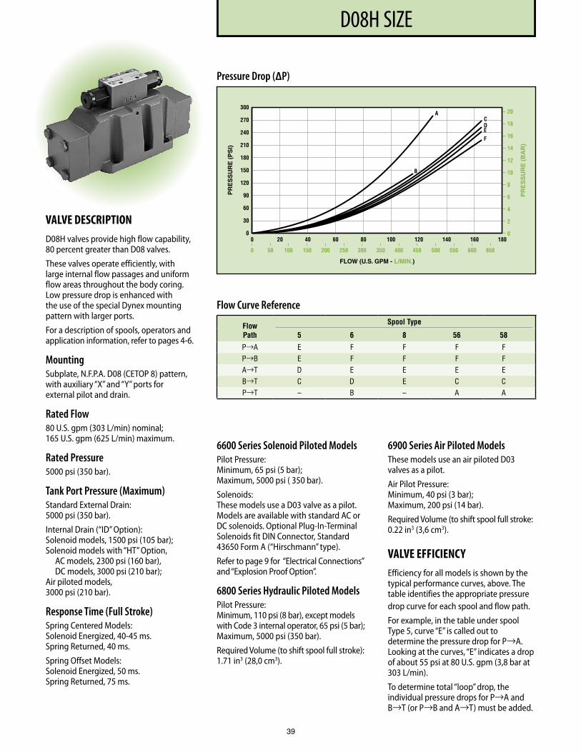
PF3000 SERIES, 10 DESIGND08H SIZE
39
VALVE DESCRIPTIOND08H valves provide high flow capability, 80 percent greater than D08 valves.
These valves operate efficiently, with large internal flow passages and uniform flow areas throughout the body coring.Low pressure drop is enhanced with the use of the special Dynex mounting pattern with larger ports.
For a description of spools, operators and application information, refer to pages 4-6.
MountingSubplate, N.F.P.A. D08 (CETOP 8) pattern, with auxiliary “X” and “Y” ports for external pilot and drain.
Rated Flow80 U.S. gpm (303 L/min) nominal; 165 U.S. gpm (625 L/min) maximum.
Rated Pressure5000 psi (350 bar).
Tank Port Pressure (Maximum)Standard External Drain: 5000 psi (350 bar).
Internal Drain (“ID” Option): Solenoid models, 1500 psi (105 bar); Solenoid models with “HT” Option, AC models, 2300 psi (160 bar), DC models, 3000 psi (210 bar); Air piloted models, 3000 psi (210 bar).
Response Time (Full Stroke)Spring Centered Models: Solenoid Energized, 40-45 ms. Spring Returned, 40 ms.
Spring Offset Models: Solenoid Energized, 50 ms. Spring Returned, 75 ms.
6600 Series Solenoid Piloted ModelsPilot Pressure: Minimum, 65 psi (5 bar); Maximum, 5000 psi ( 350 bar).
Solenoids: These models use a D03 valve as a pilot. Models are available with standard AC or DC solenoids. Optional Plug-In-Terminal Solenoids fit DIN Connector, Standard 43650 Form A (“Hirschmann” type).
Refer to page 9 for “Electrical Connections” and “Explosion Proof Option”.
6800 Series Hydraulic Piloted ModelsPilot Pressure: Minimum, 110 psi (8 bar), except models with Code 3 internal operator, 65 psi (5 bar); Maximum, 5000 psi (350 bar).
Required Volume (to shift spool full stroke): 1.71 in3 (28,0 cm3).
6900 Series Air Piloted ModelsThese models use an air piloted D03 valves as a pilot.
Air Pilot Pressure: Minimum, 40 psi (3 bar); Maximum, 200 psi (14 bar).
Required Volume (to shift spool full stroke: 0.22 in3 (3,6 cm3).
VALVE EFFICIENCYEfficiency for all models is shown by the typical performance curves, above. The table identifies the appropriate pressure drop curve for each spool and flow path.
For example, in the table under spool Type 5, curve “E” is called out to determine the pressure drop for P→A. Looking at the curves, “E” indicates a drop of about 55 psi at 80 U.S. gpm (3,8 bar at 303 L/min).
To determine total “loop” drop, the individual pressure drops for P→A and B→T (or P→B and A→T) must be added.
Flow Curve Reference
Flow Path
Spool Type
5 6 8 56 58
P→A E F F F F P→B E F F F F A→T D E E E E B→T C D E C C P→T – B – A A
Pressure Drop (∆P)
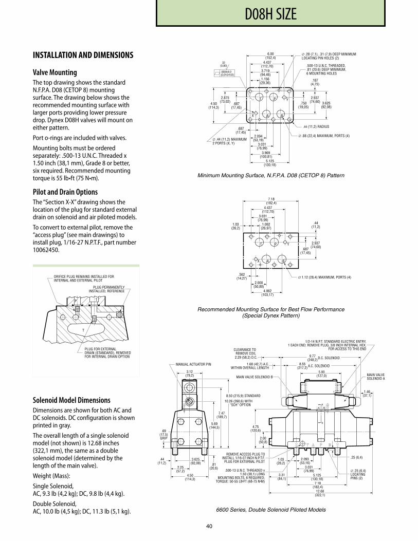
PF3000 SERIES, 10 DESIGND08H SIZE
40
INSTALLATION AND DIMENSIONS
Valve MountingThe top drawing shows the standard N.F.P.A. D08 (CETOP 8) mounting surface. The drawing below shows the recommended mounting surface with larger ports providing lower pressure drop. Dynex D08H valves will mount on either pattern.
Port o-rings are included with valves.
Mounting bolts must be ordered separately: .500-13 U.N.C. Threaded x 1.50 inch (38,1 mm), Grade 8 or better, six required. Recommended mounting torque is 55 lb•ft (75 N•m).
Pilot and Drain OptionsThe “Section X-X” drawing shows the location of the plug for standard external drain on solenoid and air piloted models.
To convert to external pilot, remove the “access plug” (see main drawings) to install plug, 1/16-27 N.P.T.F., part number 10062450.
Section X-X
PLUG FOR EXTERNALDRAIN (STANDARD), REMOVEDFOR INTERNAL DRAIN OPTION
P
T
T
ORIFICE PLUG REMAINS INSTALLED FORINTERNAL AND EXTERNAL PILOT
PLUG PERMANENTLYINSTALLED, REFERENCE
6.00 (152,4)
3.719 (94,46) 1.156
(29,36)
4.437 (112,70)
.750 (19,05)
2.937 (74,60)
.187 (4,75)
.687 (17,45)
3.969 (100,81)
2.094 (53,19)
A B
T P Y
X
∅ .88 (22,4) MAXIMUM, POR TS (4)
3.625 (92,08)
5.125 (130,18)
3.031 (76,99)
.687 (17,45)
2.875 (73,02) 4.50
(114,3)
.44 (11,2) RADIUS
.0004/ 4. 0 (0,010/102)
32 (0,80)
∅ .28 (7,1), .31 (7,9) DEEP MINIMUMLOCA TING PIN HOLES (2)
.500-13 U.N.C. THREADED,
.81 (20.6) DEEP MINIMUM, 6 MOUNTING HOLES
∅ .44 (11,2) MAXIMUM 2 POR TS (X, Y)
5.69(144,5)
7.47(189,7)
8.50 (215,9) STANDARD
.81(20,6)
.69(17,5)GRIP 2.00
(50,8)
4.75(120,6)
4.50(114,3)
2.25(57,2)
3.625(92,08)
.44(11,2)
5.125(130,18)
3.031(76,99)
3.31(84,1)
12.68(322,1)
7.18(182,4)
1.03(26,2)
8.55(217,2)
5.00(127,0)
9.77(248,2)
1.46(37,1)
3.12(79,2)
10.26 (260,6) WITH“SCH” OPTION
2.093(53,16)
X
XBA
A.C. SOLENOID
D.C. SOLENOID2.29 (58,2) D.C.
1.68 (42,7) A.C.WITHIN OVERALL LENGTH
MANUAL ACTUATOR PIN
MAIN VALVE SOLENOID B MAIN VALVESOLENOID A
∅ .25 (6,4)LOCATINGPINS (2)
.25 (6,4)REMOVE ACCESS PLUG TO
INSTALL 1/16-27 INCH N.P.T.F.PLUG FOR EXTERNAL PILOT
.500-13 U.N.C. THREADED x1.50 (38,1) LONG
MOUNTING BOLTS, 6 REQUIRED;TORQUE: 50-55 LB•FT (68-75 N•M)
1/2-14 N.P.T. STANDARD ELECTRIC ENTRY,1 EACH END; REMOVE PLUG, 3/8 INCH INTERNAL HEX,
FOR ACCESS TO THIS ENDCLEARANCE TOREMOVE COIL
Minimum Mounting Surface, N.F.P.A. D08 (CETOP 8) Pattern
6600 Series, Double Solenoid Piloted Models
7 .18(182,4)
1 .03(26,2)
3 .031(76,99)
1 .062(26,97)
4 .437(112,70)
.687(17,45)
2 .937(74,60)
.44(11,2)
.562(14,27)
4 .062(103,17)
2 .000(50,80)
A B
T P Y
X
∅ 1 .12 (28,4) MAXIMUM, PORTS (4)
Recommended Mounting Surface for Best Flow Performance (Special Dynex Pattern)
Solenoid Model DimensionsDimensions are shown for both AC and DC solenoids. DC configuration is shown printed in gray.
The overall length of a single solenoid model (not shown) is 12.68 inches (322,1 mm), the same as a double solenoid model (determined by the length of the main valve).
Weight (Mass):
Single Solenoid, AC, 9.3 lb (4,2 kg); DC, 9.8 lb (4,4 kg).
Double Solenoid, AC, 10.0 lb (4,5 kg); DC, 11.3 lb (5,1 kg).
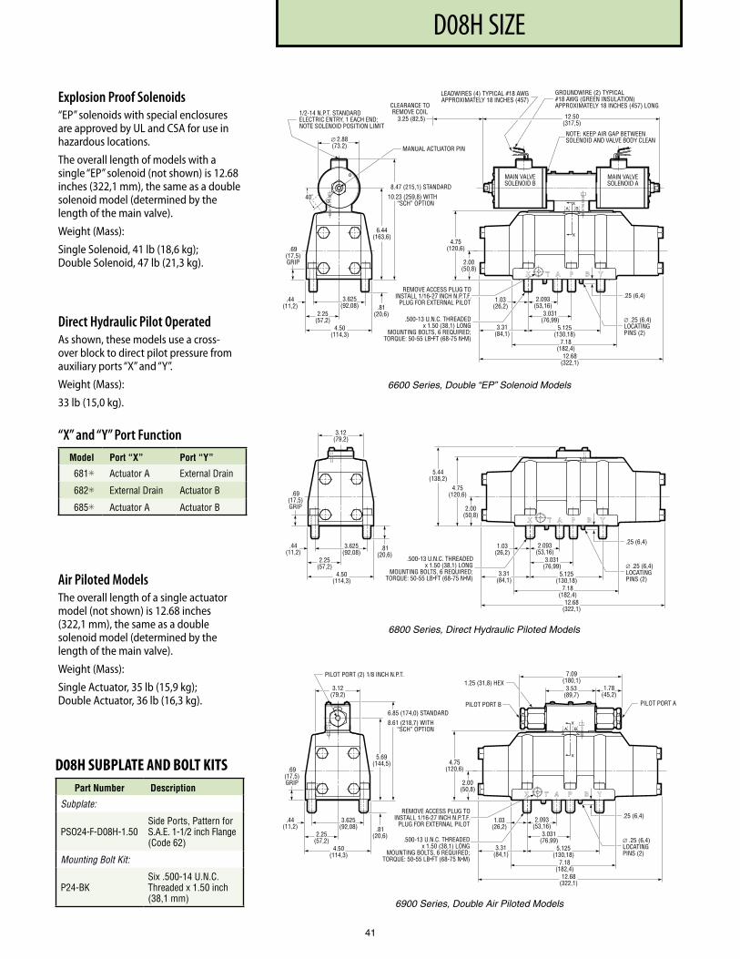
PF3000 SERIES, 10 DESIGND08H SIZE
41
Explosion Proof Solenoids“EP” solenoids with special enclosures are approved by UL and CSA for use in hazardous locations.
The overall length of models with a single “EP” solenoid (not shown) is 12.68 inches (322,1 mm), the same as a double solenoid model (determined by the length of the main valve).
Weight (Mass):
Single Solenoid, 41 lb (18,6 kg); Double Solenoid, 47 lb (21,3 kg).
Direct Hydraulic Pilot OperatedAs shown, these models use a cross-over block to direct pilot pressure from auxiliary ports “X” and “Y”.
Weight (Mass):
33 lb (15,0 kg).
“X” and “Y” Port Function Model Port “X” Port “Y”
681✳ Actuator A External Drain
682✳ External Drain Actuator B
685✳ Actuator A Actuator B
Air Piloted ModelsThe overall length of a single actuator model (not shown) is 12.68 inches (322,1 mm), the same as a double solenoid model (determined by the length of the main valve).
Weight (Mass):
Single Actuator, 35 lb (15,9 kg); Double Actuator, 36 lb (16,3 kg).
D08H SUBPLATE AND BOLT KITSPart Number Description
Subplate:
PSO24-F-D08H-1 .50Side Ports, Pattern for S .A .E . 1-1/2 inch Flange (Code 62)
Mounting Bolt Kit:
P24-BKSix .500-14 U .N .C . Threaded x 1 .50 inch (38,1 mm)
6.44(163,6)
8.47 (215,1) STANDARD
.81(20,6)
.69(17,5)GRIP 2.00
(50,8)
4.75(120,6)
4.50(114,3)
2.25(57,2)
3.625(92,08)
.44(11,2)
5.125(130,18)
3.031(76,99)
3.31(84,1)
12.68(322,1)
7.18(182,4)
1.03(26,2)
12.50(317,5)
10.23 (259,8) WITH“SCH” OPTION
2.093(53,16)
NOTE: KEEP AIR GAP BETWEENSOLENOID AND VALVE BODY CLEAN
GROUNDWIRE (2) TYPICAL#18 AWG (GREEN INSULATION)APPROXIMATELY 18 INCHES (457) LONG
LEADWIRES (4) TYPICAL #18 AWGAPPROXIMATELY 18 INCHES (457)
X
XBA
CLEARANCE TOREMOVE COIL
MANUAL ACTUATOR PIN
MAIN VALVESOLENOID B
MAIN VALVESOLENOID A
∅ .25 (6,4)LOCATINGPINS (2)
.25 (6,4)
.500-13 U.N.C. THREADEDx 1.50 (38,1) LONG
MOUNTING BOLTS, 6 REQUIRED;TORQUE: 50-55 LB•FT (68-75 N•M)
1/2-14 N.P.T. STANDARDELECTRIC ENTRY, 1 EACH END;NOTE SOLENOID POSITION LIMIT
40˚
3.25 (82,5)
∅ 2.88(73.2)
REMOVE ACCESS PLUG TO INSTALL 1/16-27 INCH N.P.T.F.
PLUG FOR EXTERNAL PILOT
5.69(144,5)
6.85 (174,0) STANDARD
.81(20,6)
.69(17,5)GRIP 2.00
(50,8)
4.75(120,6)
4.50(114,3)
2.25(57,2)
3.625(92,08)
.44(11,2)
5.125(130,18)
3.031(76,99)
3.31(84,1)
12.68(322,1)
7.18(182,4)
1.03(26,2)
7.09(180,1)
3.53(89,7)
1.78(45,2)
3.12(79,2)
8.61 (218,7) WITH“SCH” OPTION
2.093(53,16)
PILOT PORT (2) 1/8 INCH N.P.T.
X
XBA
PILOT PORT B PILOT PORT A
∅ .25 (6,4)LOCATINGPINS (2)
.25 (6,4)
.500-13 U.N.C. THREADEDx 1.50 (38,1) LONG
MOUNTING BOLTS, 6 REQUIRED;TORQUE: 50-55 LB•FT (68-75 N•M)
1.25 (31,8) HEX
REMOVE ACCESS PLUG TO INSTALL 1/16-27 INCH N.P.T.F.
PLUG FOR EXTERNAL PILOT
6600 Series, Double “EP” Solenoid Models
6900 Series, Double Air Piloted Models
5.44(138,2)
.81(20,6)
.69(17,5)GRIP 2.00
(50,8)
4.75(120,6)
4.50(114,3)
2.25(57,2)
3.625(92,08)
.44(11,2)
5.125(130,18)
3.031(76,99)
3.31(84,1)
12.68(322,1)
7.18(182,4)
1.03(26,2)
3.12(79,2)
2.093(53,16)
∅ .25 (6,4)LOCATINGPINS (2)
.25 (6,4)
.500-13 U.N.C. THREADED x 1.50 (38,1) LONG
MOUNTING BOLTS, 6 REQUIRED;TORQUE: 50-55 LB•FT (68-75 N•M)
6800 Series, Direct Hydraulic Piloted Models
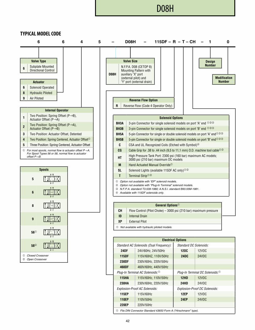
PF3000 SERIES, 10 DESIGND08H
42
Actuator
6 Solenoid Operated
8 Hydraulic Piloted
9 Air Piloted
6 6 4 5 – D08H – 115DF – R – T – CH – 1 0
Valve Type
6 Subplate Mounted Directional Control
Solenoid Options
BH3A 3-pin Connector for single solenoid models on port "A" end ➂
BH3B 3-pin Connector for single solenoid models on port "B" end ➂
BH5A 5-pin Connector for single or double solenoid models on port "A" end➂
BH5B 5-pin Connector for single or double solenoid models on port "B" end➂
C CSA and UL Recognized Coils (Etched with Symbol)➃
CG Cable Grip for .38 to .44 inch (9,5 to 11,1 mm) O .D . machine tool cable
HT High Pressure Tank Port: 2300 psi (160 bar) maximum AC models; 3000 psi (210 bar) maximum DC models
M Hand Actuated Manual Override
SL Solenoid Lights (available 115DF AC only)
T Terminal Strip
Option not available with “EP” solenoid models. Option not available with “Plug-In Terminal” solenoid models. ➂ N.F.P.A. standard T3.539-1980; A.N.S.I. standard B93.55M-1981. ➃ Available with 115DF solenoids only.
Design Number
Modification Number
TYPICAL MODEL CODE
Electrical Options
Standard AC Solenoids (Dual Frequency): Standard DC Solenoids:
24DF 24V/60Hz, 24V/50Hz 12DC 12VDC
115DF 115V/60HZ, 110V/50Hz 24DC 24VDC
230DF 230V/60Hz, 220V/50Hz
460DF 460V/60Hz, 440V/50Hz
Plug-In Terminal AC Solenoids: Plug-In Terminal DC Solenoids:
115HA 115V/60Hz, 110V/50Hz 12HD 12VDC
230HA 230V/60Hz, 220V/50Hz 24HD 24VDC
Explosion-Proof AC Solenoids: Explosion-Proof DC Solenoids:
115EP 115V/60Hz 12EP 12VDC
110EP 110V/50Hz 24EP 24VDC
220EP 220V/50Hz
Fits DIN Connector Standard 43650 Form A (“Hirschmann” type).
Reverse Flow Option
R Reverse Flow (Code 4 Operator Only)
Valve Size
D08H
N .F .P .A . D08 (CETOP 8) Mounting Pattern with auxiliary "X" port (external pilot) and "Y" port (external drain)
Internal Operator
1 Two Position: Spring Offset (P→B), Actuator Offset (P→A)
2 Two Position: Spring Offset (P→A), Actuator Offset (P→B)
3 Two Position: Actuator Offset, Detented
4 Two Position: Spring Centered, Actuator Offset
5 Three Position: Spring Centered, Actuator Offset
For most spools, normal flow is actuator offset P→A. For Spool Types 56 or 58, normal flow is actuator offset P→B.
Spools
5
6
8
9
56
58
Closed Crossover Open Crossover
A B
P T
A B
P T
A B
P T
A B
P T
A B
P T
A B
P T
General Options
CH Flow Control (Pilot Choke) – 3000 psi (210 bar) maximum pressure
ID Internal Drain
XP External Pilot
Not available with hydraulic piloted models.
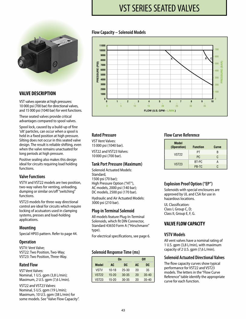
PF3000 SERIES, 10 DESIGNVST SERIES SEATED VALVES
43
VALVE DESCRIPTIONVST valves operate at high pressures: 10 000 psi (700 bar) for directional valves, and 15 000 psi (1040 bar) for vent functions.
These seated valves provide critical advantages compared to spool valves.
Spool lock, caused by a build-up of fine ‘silt’ particles, can occur when a spool is held in a fixed position at high pressure. Silting does not occur in this seated valve design. The result is reliable shifting, even when the valve remains unactuated for long periods at high pressure.
Positive sealing also makes this design ideal for circuits requiring load holding functions.
Valve FunctionsVSTV and VST22 models are two position, two-way valves for venting, unloading, dumping or similar on/off “switching” functions.
VST23 models for three-way directional control are ideal for circuits which require locking of acutuators used in clamping systems, presses and load-holding applications.
MountingSpecial HP03 pattern. Refer to page 44.
OperationVSTV: Vent Valve; VST22: Two Position, Two-Way; VST23: Two Position, Three-Way.
Rated FlowVST Vent Valves: Nominal, 1 U.S. gpm (3,8 L/min); Maximum, 2 U.S. gpm (7,6 L/min).
VST22 and VST23 Valves: Nominal, 5 U.S. gpm (19 L/min); Maximum, 10 U.S. gpm (38 L/min) for some models. See “Valve Flow Capacity”.
Rated PressureVST Vent Valves: 15 000 psi (1040 bar).
VST22 and VST23 Valves: 10 000 psi (700 bar).
Tank Port Pressure (Maximum)Solenoid Actuated Models: Standard, 1500 psi (70 bar); High Pressure Option (“HT”), AC models, 2000 psi (140 bar); DC models, 2500 psi (170 bar).
Hydraulic and Air Actuated Models: 3000 psi (210 bar).
Plug-in Terminal SolenoidAll models feature Plug-In-Terminal Solenoids, which fit DIN Connector, Standard 43650 Form A (“Hirschmann” type).
For electrical specifications, see page 6.
Explosion Proof Option (“EP”)Solenoids with special enclosures are approved by UL and CSA for use in hazardous locations.
UL Classification: Class I, Group C, D; Class II, Group E, F, G.
VALVE FLOW CAPACITY
VSTV ModelsAll vent valves have a nominal rating of 1 U.S. gpm (3,8 L/min), with maximum capacity of 2 U.S. gpm (7,6 L/min).
Solenoid Actuated Directional ValvesThe flow capacity curves show typical performance for VST22 and VST23 models. The letters in the “Flow Curve Reference” table identify the appropriate curve for each function.
Flow Capacity – Solenoid Models
Solenoid Response Time (ms) On Off
Model AC DC AC DC
VSTV 10-18 25-30 20 35VST22 15-20 30-35 20 35-40VST23 15-20 30-35 20 35-40
Flow Curve Reference
Model (Operation) Function Curve
VST22PT BPC C
VST23BT-PC APB-TC C
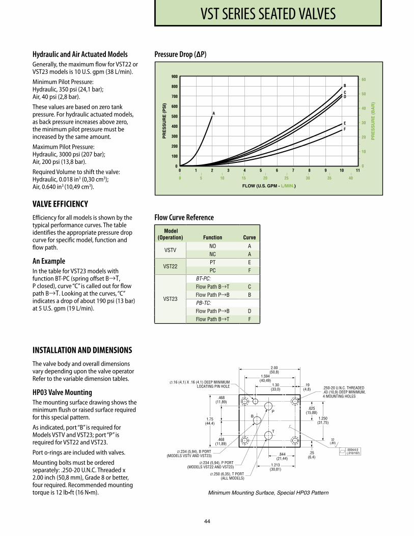
PF3000 SERIES, 10 DESIGNVST SERIES SEATED VALVES
44
Hydraulic and Air Actuated ModelsGenerally, the maximum flow for VST22 or VST23 models is 10 U.S. gpm (38 L/min).
Minimum Pilot Pressure: Hydraulic, 350 psi (24,1 bar); Air, 40 psi (2,8 bar).
These values are based on zero tank pressure. For hydraulic actuated models, as back pressure increases above zero, the minimum pilot pressure must be increased by the same amount.
Maximum Pilot Pressure: Hydraulic, 3000 psi (207 bar); Air, 200 psi (13,8 bar).
Required Volume to shift the valve: Hydraulic, 0.018 in3 (0,30 cm3); Air, 0.640 in3 (10,49 cm3).
VALVE EFFICIENCYEfficiency for all models is shown by the typical performance curves. The table identifies the appropriate pressure drop curve for specific model, function and flow path.
An ExampleIn the table for VST23 models with function BT-PC (spring offset B→T, P closed), curve “C” is called out for flow path B→T. Looking at the curves, “C” indicates a drop of about 190 psi (13 bar) at 5 U.S. gpm (19 L/min).
INSTALLATION AND DIMENSIONSThe valve body and overall dimen sions vary depending upon the valve operator Refer to the variable dimension tables.
HP03 Valve MountingThe mounting surface drawing shows the minimum flush or raised surface required for this special pattern.
As indicated, port “B” is required for Models VSTV and VST23; port “P” is required for VST22 and VST23.
Port o-rings are included with valves.
Mounting bolts must be ordered separately: .250-20 U.N.C. Threaded x 2.00 inch (50,8 mm), Grade 8 or better, four required. Recommended mounting torque is 12 lb•ft (16 N•m).
∅.16 (4,1) X .16 (4,1) DEEP MINIMUM LOCATING PIN HOLE
.0004/ 4. 0 (,010/102)
32 (,80)
1.75 (44,4)
1.30 (33,0)
1.594 (40,49)
2.00 (50,8)
.19 (4,8 )
.25 (6,4 )
.625 (15,88)
1.250 (31,75)
.844 (21,44)
.250-20 U.N.C. THREADED
.43 (10,9) DEEP MINIMUM,4 MOUNTING HOLES
P
T
.468 (11,89)
.468 (11,89)
∅.234 (5,94), P PORT (MODELS VST22 AND VST23)
∅.250 (6,35), T PORT (ALL MODELS)
∅.234 (5,94), B PORT (MODELS VSTV AND VST23)
B
1.213 (30,81)
Minimum Mounting Surface, Special HP03 Pattern
Pressure Drop (∆P)
Flow Curve Reference
Model (Operation) Function Curve
VSTVNO ANC A
VST22PT EPC F
VST23
BT-PC:Flow Path B→T CFlow Path P→B B
PB-TC:Flow Path P→B DFlow Path B→T F
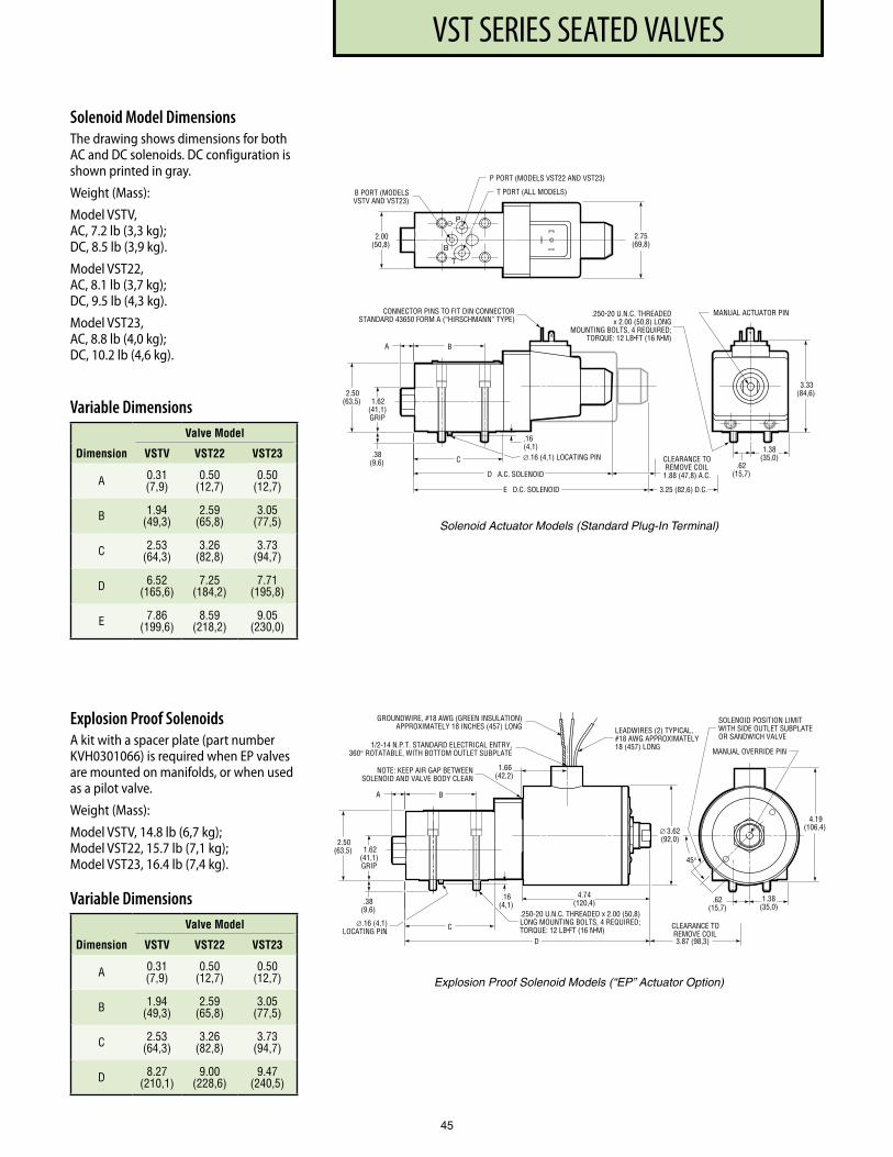
PF3000 SERIES, 10 DESIGNVST SERIES SEATED VALVES
45
Solenoid Model DimensionsThe drawing shows dimensions for both AC and DC solenoids. DC configuration is shown printed in gray.
Weight (Mass):
Model VSTV, AC, 7.2 lb (3,3 kg); DC, 8.5 lb (3,9 kg).
Model VST22, AC, 8.1 lb (3,7 kg); DC, 9.5 lb (4,3 kg).
Model VST23, AC, 8.8 lb (4,0 kg); DC, 10.2 lb (4,6 kg).
Variable Dimensions Valve Model
Dimension VSTV VST22 VST23
A 0 .31 (7,9)
0 .50 (12,7)
0 .50 (12,7)
B 1 .94 (49,3)
2 .59 (65,8)
3 .05 (77,5)
C 2 .53 (64,3)
3 .26 (82,8)
3 .73 (94,7)
D 6 .52 (165,6)
7 .25 (184,2)
7 .71 (195,8)
E 7 .86 (199,6)
8 .59 (218,2)
9 .05 (230,0)
Explosion Proof SolenoidsA kit with a spacer plate (part number KVH0301066) is required when EP valves are mounted on manifolds, or when used as a pilot valve.
Weight (Mass):
Model VSTV, 14.8 lb (6,7 kg); Model VST22, 15.7 lb (7,1 kg); Model VST23, 16.4 lb (7,4 kg).
.38(9,6)
.16(4,1)
2.50(63,5)
A B
C
D
∅.16 (4,1) LOCATING PIN
1.62(41,1)GRIP
3.87 (98,3)
CLEARANCE TO REMOVE COIL
LEADWIRES (2) TYPICAL,#18 AWG APPROXIMATELY18 (457) LONG
GROUNDWIRE, #18 AWG (GREEN INSULATION) APPROXIMATELY 18 INCHES (457) LONG
1/2-14 N.P.T. STANDARD ELECTRICAL ENTRY, 360° ROTATABLE, WITH BOTTOM OUTLET SUBPLATE
1.66(42,2)
NOTE: KEEP AIR GAP BETWEEN SOLENOID AND VALVE BODY CLEAN
∅ 3.62(92,0)
4.74(120,4)
SOLENOID POSITION LIMITWITH SIDE OUTLET SUBPLATEOR SANDWICH VALVE
45°
MANUAL OVERRIDE PIN
.62(15,7)
1.38(35,0)
4.19(106,4)
.250-20 U.N.C. THREADED x 2.00 (50,8)LONG MOUNTING BOLTS, 4 REQUIRED;TORQUE: 12 LB•FT (16 N•M)
Explosion Proof Solenoid Models (“EP” Actuator Option)
.
.38 (9,6) .62
(15,7)
.16 (4,1) 1.38
(35,0)
2.50 (63,5)
A B
CONNECTOR PINS TO FIT DIN CONNECTOR STANDARD 43650 FORM A (“HIRSCHMANN” TYPE)
C
D A.C. SOLENOI D
E D.C. SOLENOI D 3.25 (82,6) D.C.
CLEARANCE TO REMOVE COIL 1.88 (47,8) A.C.
MANUAL ACTUATOR PI N
3.3 3 (84,6)
∅.16 (4,1) LOCATING PIN
2.00 (50,8)
2.75 (69,8)
1.62 (41,1) GRIP
P
T
P PORT (MODELS VST22 AND VST23)
T PORT (ALL MODELS) B PORT (MODELS VSTV AND VST23)
B
.250-20 U.N.C. THREADED x 2.00 (50,8) LONG
MOUNTING BOLTS, 4 REQUIRED; TORQUE: 12 LB • FT (16 N • M)
Solenoid Actuator Models (Standard Plug-In Terminal)
Variable Dimensions Valve Model
Dimension VSTV VST22 VST23
A 0 .31 (7,9)
0 .50 (12,7)
0 .50 (12,7)
B 1 .94 (49,3)
2 .59 (65,8)
3 .05 (77,5)
C 2 .53 (64,3)
3 .26 (82,8)
3 .73 (94,7)
D 8 .27 (210,1)
9 .00 (228,6)
9 .47 (240,5)
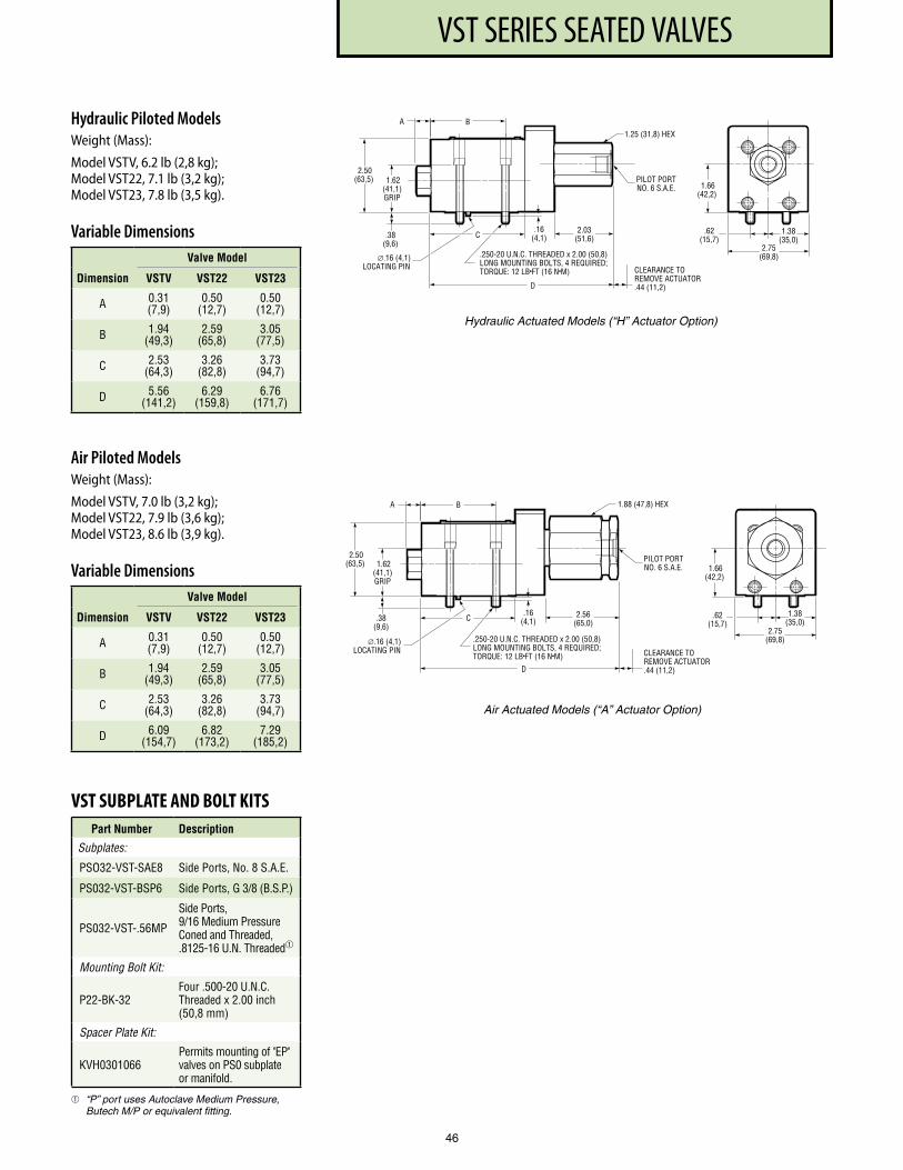
PF3000 SERIES, 10 DESIGNVST SERIES SEATED VALVES
46
Hydraulic Piloted ModelsWeight (Mass):
Model VSTV, 6.2 lb (2,8 kg); Model VST22, 7.1 lb (3,2 kg); Model VST23, 7.8 lb (3,5 kg).
Variable Dimensions Valve Model
Dimension VSTV VST22 VST23
A 0 .31 (7,9)
0 .50 (12,7)
0 .50 (12,7)
B 1 .94 (49,3)
2 .59 (65,8)
3 .05 (77,5)
C 2 .53 (64,3)
3 .26 (82,8)
3 .73 (94,7)
D 5 .56 (141,2)
6 .29 (159,8)
6 .76 (171,7)
Air Piloted ModelsWeight (Mass):
Model VSTV, 7.0 lb (3,2 kg); Model VST22, 7.9 lb (3,6 kg); Model VST23, 8.6 lb (3,9 kg).
Variable Dimensions Valve Model
Dimension VSTV VST22 VST23
A 0 .31 (7,9)
0 .50 (12,7)
0 .50 (12,7)
B 1 .94 (49,3)
2 .59 (65,8)
3 .05 (77,5)
C 2 .53 (64,3)
3 .26 (82,8)
3 .73 (94,7)
D 6 .09 (154,7)
6 .82 (173,2)
7 .29 (185,2)
.38(9,6)
.16(4,1)
.
2.50(63,5)
A B
C
D
CLEARANCE TOREMOVE ACTUATOR.44 (11,2)
1.62(41,1)GRIP
.250-20 U.N.C. THREADED x 2.00 (50,8)LONG MOUNTING BOLTS, 4 REQUIRED;TORQUE: 12 LB•FT (16 N•M)
2.56(65,0)
∅.16 (4,1) LOCATING PIN
1.88 (47,8) HEX
PILOT PORTNO. 6 S.A.E.
2.75(69,8)
.62(15,7)
1.38(35,0)
1.66(42,2)
Air Actuated Models (“A” Actuator Option)
2.75(69,8)
.62(15,7)
1.38(35,0)
1.66(42,2)
.38(9,6)
.16(4,1)
.
2.50(63,5)
A B
C
D
CLEARANCE TOREMOVE ACTUATOR.44 (11,2)
1.62(41,1)GRIP
.250-20 U.N.C. THREADED x 2.00 (50,8)LONG MOUNTING BOLTS, 4 REQUIRED;TORQUE: 12 LB•FT (16 N•M)
2.03(51,6)
∅.16 (4,1) LOCATING PIN
1.25 (31,8) HEX
PILOT PORTNO. 6 S.A.E.
Hydraulic Actuated Models (“H” Actuator Option)
VST SUBPLATE AND BOLT KITSPart Number Description
Subplates:
PSO32-VST-SAE8 Side Ports, No . 8 S .A .E .
PS032-VST-BSP6 Side Ports, G 3/8 (B .S .P .)
PS032-VST- .56MP
Side Ports, 9/16 Medium Pressure Coned and Threaded, .8125-16 U .N . Threaded
Mounting Bolt Kit:
P22-BK-32Four .500-20 U .N .C . Threaded x 2 .00 inch (50,8 mm)
Spacer Plate Kit:
KVH0301066Permits mounting of "EP" valves on PS0 subplate or manifold .
“P” port uses Autoclave Medium Pressure, Butech M/P or equivalent fitting.
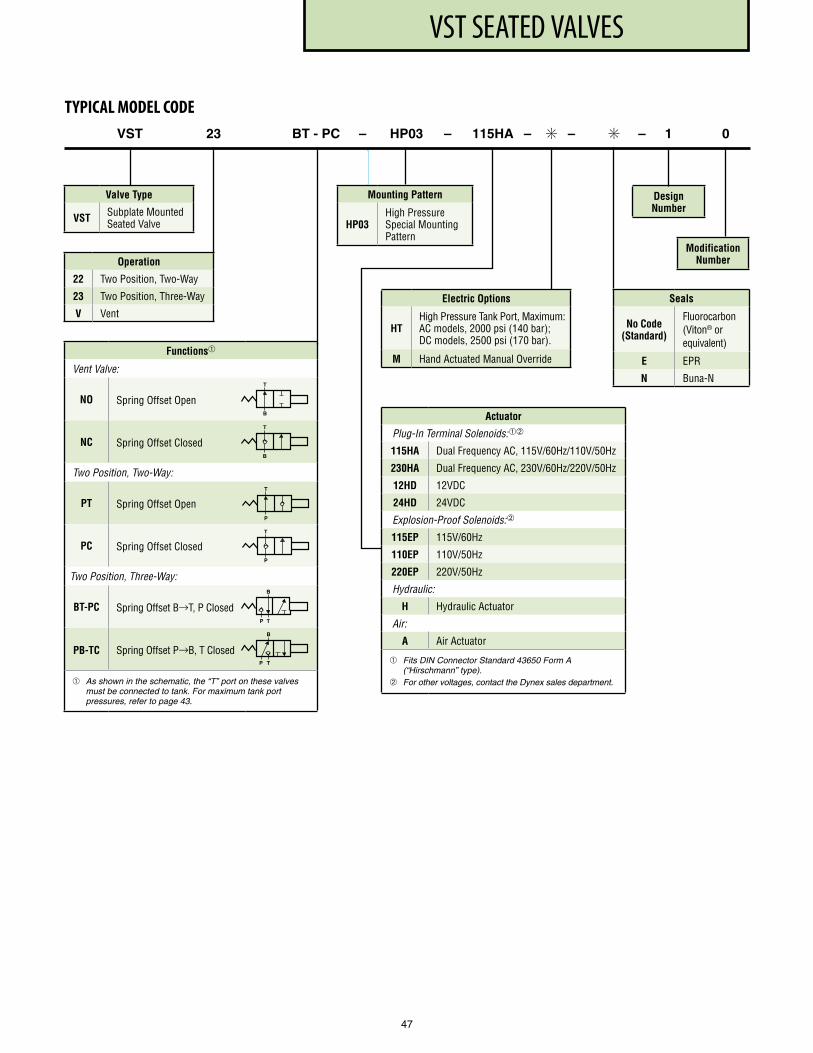
VST SEATED VALVES
Operation
22 Two Position, Two-Way
23 Two Position, Three-Way
V Vent
VST 23 BT - PC – HP03 – 115HA – ✳ – ✳ – 1 0
Valve Type
VST Subplate Mounted Seated Valve
TYPICAL MODEL CODE
Functions
Vent Valve:
NO Spring Offset Open
NC Spring Offset Closed
Two Position, Two-Way:
PT Spring Offset Open
PC Spring Offset Closed
Two Position, Three-Way:
BT-PC Spring Offset B→T, P Closed
PB-TC Spring Offset P→B, T Closed
As shown in the schematic, the “T” port on these valves must be connected to tank. For maximum tank port pressures, refer to page 43.
Actuator
Plug-In Terminal Solenoids:
115HA Dual Frequency AC, 115V/60Hz/110V/50Hz
230HA Dual Frequency AC, 230V/60Hz/220V/50Hz
12HD 12VDC
24HD 24VDC
Explosion-Proof Solenoids:
115EP 115V/60Hz
110EP 110V/50Hz
220EP 220V/50Hz
Hydraulic:
H Hydraulic Actuator
Air:
A Air Actuator
Fits DIN Connector Standard 43650 Form A (“Hirschmann” type).
For other voltages, contact the Dynex sales department.
Electric Options
HTHigh Pressure Tank Port, Maximum: AC models, 2000 psi (140 bar); DC models, 2500 psi (170 bar) .
M Hand Actuated Manual Override
B
T
B
T
P
P
T
T
B
T
B
T
P
P
Seals
No Code (Standard)
Fluorocarbon (Viton® or equivalent)
E EPR
N Buna-N
Mounting Pattern
HP03High Pressure Special Mounting Pattern
Design Number
Modification Number
47
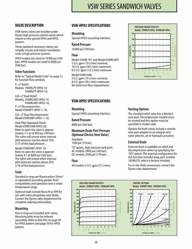
VSW SERIES SANDWICH VALVES
48
PRESSURE CHARACTERISTICS Models: VSWRLPT-HP03, VSWRLABT-HP03
PRESSURE CHARACTERISTICS Models: VSWRLPT-HP05, VSWRLABT-HP05
CONTROL SETTINGS Models: VSWDPT-HP05, VSWDABT-HP05
VALVE DESCRIPTIONVSW Series valves are installed under Dynex high pressure control valves which mount on the special HP03 and HP05 pattern.
These sandwich accessory valves can simplify circuits and reduce installation costs in high pressure systems.
HP03 models are rated to 10 000 psi (700 bar). HP05 models are rated to 8000 psi (560 bar).
Valve FunctionsRefer to “Typical Model Code” on page 51 for function flow symbols.
P→T Relief: Models, VSWRLPT-HP03-10 VSWRLPT-HP05-10;
A,B→T Dual Relief: Models, VSWRLABT-HP03-10 VSWRLABT-HP05-10; P→T Decompression: Model VSWDPT-HP05-✳-10;
A,B→T Dual Decompression: Model VSWDABT-HP05-✳-10;
Dual Pilot Operated Check: Model VSWCHAB-HP03-20; Ratio to open the valve is approx- imately 7:1 at 10 000 psi (700 bar). The valve will unseat when internal pilot pressure reaches about 14% (1/7) of the load pressure.
Model VSWDABT-HP05-10; Ratio to open the valve is approxi - mately 4:1 at 8000 psi (560 bar). The valve will unseat when internal pilot pressure reaches about 25% (1/4) of the load pressure.
SealsStandard o-rings are fluorocarbon (Viton® or equivalent) providing greater fluid compatibility and operation over a wider temperature range.
Optional seals include Buna-N or EPR for use with some phosphate ester fluids. Contact the Dynex sales depart ment for complete ordering information.
MountingPort o-rings are included with valves. Mounting bolts must be ordered separately. Refer to Bolt Kits on page 49 for HP03 pattern and page 50 for HP05 pattern.
VSW-HP03 SPECIFICATIONS
MountingSpecial HP03 mounting interface.
Rated Pressure10 000 psi (700 bar).
FlowModel VSWRL1PT and Model VSWRLABT: 5 U.S. gpm (19 L/min) nominal; 10 U.S. gpm (38 L/min) max imum; 0.5 U.S. gpm (1,9 L/min) minimum.
Model VSWCHAB: 5 U.S. gpm (19 L/min) nominal; 8 U.S. gpm (30 L/min) maximum; No minimum flow requirements.
VSW-HP05 SPECIFICATIONS
MountingSpecial HP05 mounting interface.
Rated Pressure8000 psi (560 bar).
Maximum Drain Port Pressure (Optional Electric Vent Valve)Standard: 1500 psi (70 bar);
“D” option, high pressure tank port: AC models, 2000 psi (140 bar); DC models, 2500 psi (170 bar).
FlowAll models: 5 U.S. gpm (57 L/min).
Venting OptionsThe standard relief valve has a blocked vent port. Decompression models must be vented and this option must be specified in model code.
Options for both valves include a remote vent port adapter or an integral vent valve (electric, air or hydraulic actuator).
External DrainExternal drain is available on relief and decompression valves by specifying the “XD” option. The internal configuration for this function includes plug, part number 10590270, which is factory installed.
For in-the-field conversions, contact the Dynex sales department.
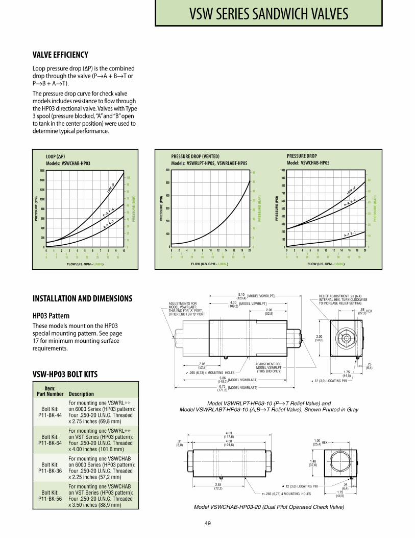
VSW SERIES SANDWICH VALVES
49
LOOP (∆P) Models: VSWCHAB-HP03
PRESSURE DROP (VENTED) Models: VSWRLPT-HP05, VSWRLABT-HP05
PRESSURE DROP Model: VSWCHAB-HP05
VALVE EFFICIENCYLoop pressure drop (∆P) is the combined drop through the valve (P→A + B→T or P→B + A→T).
The pressure drop curve for check valve models includes resistance to flow through the HP03 directional valve. Valves with Type 3 spool (pressure blocked, “A” and “B” open to tank in the center position) were used to determine typical performance.
INSTALLATION AND DIMENSIONS
HP03 PatternThese models mount on the HP03 special mounting pattern. See page 17 for minimum mounting surface requirements.
VSW-HP03 BOLT KITSItem:
Part Number Description
Bolt Kit: P11-BK-44
For mounting one VSWRL✳✳ on 6000 Series (HP03 pattern): Four .250-20 U .N .C . Threaded x 2 .75 inches (69,8 mm)
Bolt Kit: P11-BK-64
For mounting one VSWRL✳✳ on VST Series (HP03 pattern): Four .250-20 U .N .C . Threaded x 4 .00 inches (101,6 mm)
Bolt Kit: P11-BK-36
For mounting one VSWCHAB on 6000 Series (HP03 pattern): Four .250-20 U .N .C . Threaded x 2 .25 inches (57,2 mm)
Bolt Kit: P11-BK-56
For mounting one VSWCHAB on VST Series (HP03 pattern): Four .250-20 U .N .C . Threaded x 3 .50 inches (88,9 mm)
1 .00(25,4)
.31(8,0)
4 .00(101,6)
4 .63(117,6)
2 .84(72,2)
.265 (6,73) 4 MOUNTING HOLES
.25(6,4)
1 .75(44,5)
1 .48(37,6)
.12 (3,0) LOCATING PIN
HEX
Model VSWCHAB-HP03-20 (Dual Pilot Operated Check Valve)
Model VSWRLPT-HP03-10 (P→T Relief Valve) and Model VSWRLABT-HP03-10 (A,B→T Relief Valve), Shown Printed in Gray
[MODEL VSWRLPT]
[MODEL VSWRLPT]
ADJUSTMENT FOR MODEL VSWRLPT(THIS END ONLY)
2.08(52,9)
[MODEL VSWRLABT]
[MODEL VSWRLABT]
ADJUSTMENTS FORMODEL VSWRLABT;THIS END FOR "A" PORT,OTHER END FOR "B" PORT
.265 (6,73) 4 MOUNTING HOLES
.12 (3,0) LOCATING PIN
.25(6,4)
1.75(44,5)
4.30(109,2)
5.10(129,4)
.88(22,2)HEX
2.00(50,8)
RELIEF ADJUSTMENT .25 (6,4)INTERNAL HEX. TURN CLOCKWISETO INCREASE RELIEF SETTING
5.86(148,7)6.75
(171,6)
2.08(52,9)
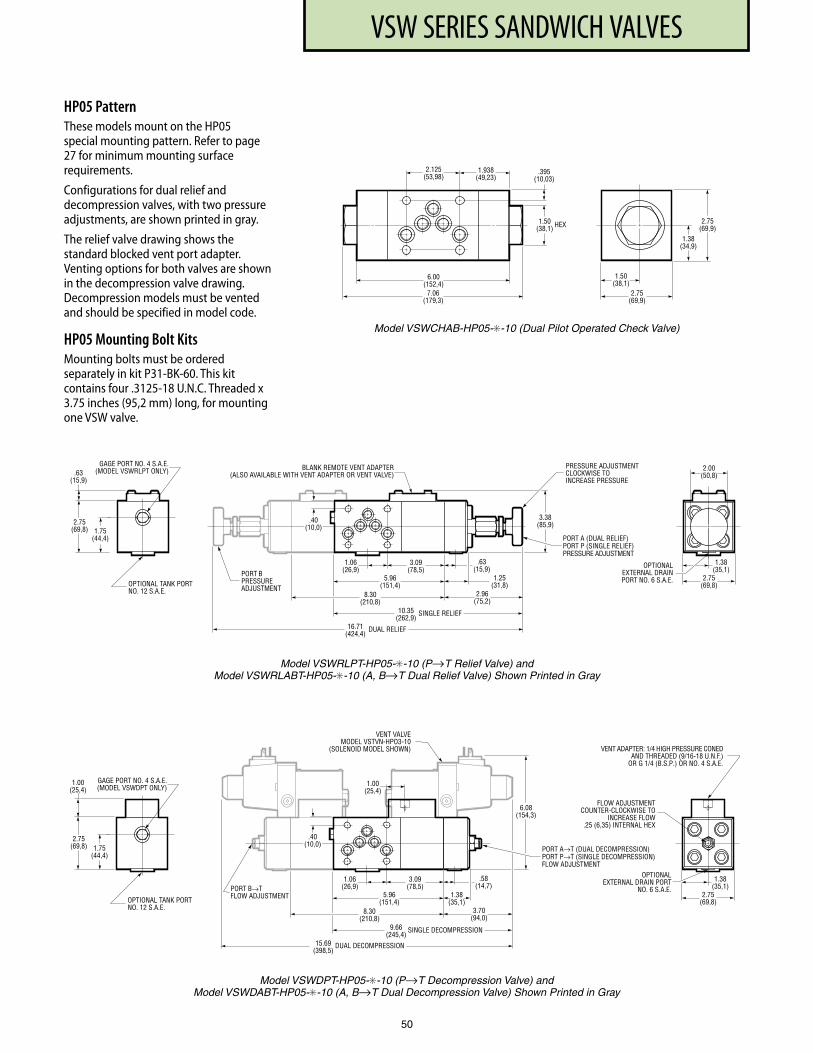
VSW SERIES SANDWICH VALVES
50
HP05 PatternThese models mount on the HP05 special mounting pattern. Refer to page 27 for minimum mounting surface requirements.
Configurations for dual relief and decompression valves, with two pressure adjust ments, are shown printed in gray.
The relief valve drawing shows the standard blocked vent port adapter. Venting options for both valves are shown in the decompression valve drawing. Decompression models must be vented and should be specified in model code.
HP05 Mounting Bolt KitsMounting bolts must be ordered separately in kit P31-BK-60. This kit contains four .3125-18 U.N.C. Threaded x 3.75 inches (95,2 mm) long, for mounting one VSW valve.
6 .00(152,4)
7 .06(179,3)
1 .938(49,23)
2 .125(53,98)
.395(10,03)
1 .38(34,9)
2 .75(69,9)
1 .50(38,1)
2 .75(69,9)
1 .50(38,1) HEX
Model VSWCHAB-HP05-✳-10 (Dual Pilot Operated Check Valve)
Model VSWRLPT-HP05-✳-10 (P→T Relief Valve) and Model VSWRLABT-HP05-✳-10 (A, B→T Dual Relief Valve) Shown Printed in Gray
8.30(210,8)
3.09(78,5)
5.96(151,4)
1.25(31,8)
.63(15,9)
2.96(75,2)
16.71(424,4)
DUAL RELIEF
10.35(262,9)
SINGLE RELIEF
1.38(35,1)
2.75(69,8)
3.38(85,9)
1.75(44,4)
2.75(69,8)
BLANK REMOTE VENT ADAPTER(ALSO AVAILABLE WITH VENT ADAPTER OR VENT VALVE).63
(15,9)
PRESSURE ADJUSTMENTCLOCKWISE TOINCREASE PRESSURE
PORT BPRESSUREADJUSTMENT
PORT A (DUAL RELIEF)PORT P (SINGLE RELIEF)PRESSURE ADJUSTMENT
2.00(50,8)
OPTIONAL TANK PORTNO. 12 S.A.E.
GAGE PORT NO. 4 S.A.E.(MODEL VSWRLPT ONLY)
OPTIONALEXTERNAL DRAINPORT NO. 6 S.A.E.
1.06(26,9)
.40(10,0)
Model VSWDPT-HP05-✳-10 (P→T Decompression Valve) and Model VSWDABT-HP05-✳-10 (A, B→T Dual Decompression Valve) Shown Printed in Gray
8.30(210,8)
3.09(78,5)
5.96(151,4)
.58(14,7)
3.70(94,0)
15.69(398,5)
DUAL DECOMPRESSION
9.66(245,4)
SINGLE DECOMPRESSION
1.38(35,1)
1.38(35,1)
2.75(69,8)
6.08(154,3)
1.75(44,4)
2.75(69,8)
.40
VENT ADAPTER: 1/4 HIGH PRESSURE CONEDAND THREADED (9/16-18 U.N.F.)
OR G 1/4 (B.S.P.) OR NO. 4 S.A.E.
1.00(25,4)
FLOW ADJUSTMENTCOUNTER-CLOCKWISE TO
INCREASE FLOW.25 (6,35) INTERNAL HEX
OPTIONAL TANK PORTNO. 12 S.A.E.
PORT B→TFLOW ADJUSTMENT
PORT A→T (DUAL DECOMPRESSION)PORT P→T (SINGLE DECOMPRESSION)FLOW ADJUSTMENT
OPTIONALEXTERNAL DRAIN PORT
NO. 6 S.A.E.
VENT VALVEMODEL VSTVN-HPO3-10
(SOLENOID MODEL SHOWN)
1.00(25,4)
1.06(26,9)
GAGE PORT NO. 4 S.A.E.(MODEL VSWDPT ONLY)
(10,0)
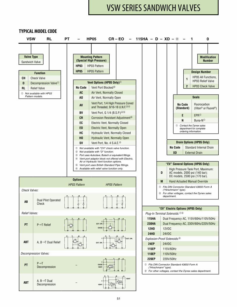
VSW SERIES SANDWICH VALVES
Function
CH Check Valve
D Decompression Valve
RL Relief Valve
Not available with HP03 Pattern models.
VSW RL PT – HP05 CR – EO – 115HA – D – XD – ✳ – 1 0
Valve Type
Sandwich Valve
TYPICAL MODEL CODE
“EV” Electric Options (HP05 Only)
Plug-In Terminal Solenoids:
115HA Dual Frequency AC, 115V/60Hz/110V/50Hz
230HA Dual Frequency AC, 230V/60Hz/220V/50Hz
12HD 12VDC
24HD 24VDC
Explosion-Proof Solenoids:
24EP 24VDC
115EP 115V/60Hz
110EP 110V/50Hz
220EP 220V/50Hz
Fits DIN Connector Standard 43650 Form A (“Hirschmann” type).
For other voltages, contact the Dynex sales department.
Design Number
1HP05 All Functions, HP03 Relief Valve
2 HP03 Check Valve
Mounting Pattern (Special High Pressure)
HP03 HP03 Pattern
HP05 HP05 Pattern
Modification Number
Seals
No Code(Standard)
Fluorocarbon (Viton® or Fluorel®)
E EPR
N Buna-N
Contact the Dynex sales department for complete ordering information.
Options
HP03 Pattern HP05 Pattern
Check Valves:
AB Dual Pilot Operated Check
Relief Valves:
PT P→T Relief
ABT A, B→T Dual Relief
Decompression Valves:
PT P→T Decompression –
ABT A, B→T Dual Decompression –
T B
EXT. DR.
P A
T
GAGE
T B
GAGE
P A
T
VENT
T BP A
T
VENT
VENT
T B
EXT. DR.
EXT. DR.
P AT
T BP A
T BP A
T BP A
T BP A
Vent Options (HP05 Only)
No Code Vent Port Blocked
AC Air Vent, Normally Closed
AO Air Vent, Normally Open
AVVent Port, 1/4 High Pressure Coned and Threaded, 9/16-18 U.N.F.➂➃
BV Vent Port, G 1/4 (B.S.P.)➃➄
CR Corrosion Resistant Adjustment➅
EC Electric Vent, Normally Closed
EO Electric Vent, Normally Open
HC Hydraulic Vent, Normally Closed
HO Hydraulic Vent, Normally Open
SV Vent Port, No. 4 S.A.E.➃
Not available with "CH" check valve function. Not available with "D" function. ➂ Port uses Autoclave, Butech or equivalent fittings.➃ Vent port adaptor block not offered with Electric,
Air or Hydraulic Vent function options.➄ Vent port uses British Standard Pipe fittings.➅ Available with relief valve function only.
Drain Options (HP05 Only)
No Code Standard Internal Drain
XD External Drain
51
“EV” General Options (HP05 Only)
DHigh Pressure Tank Port, Maximum: AC models, 2000 psi (140 bar); DC models, 2500 psi (170 bar).
M Hand Actuated Manual Override
Fits DIN Connector Standard 43650 Form A (“Hirschmann” type).
For other voltages, contact the Dynex sales department.
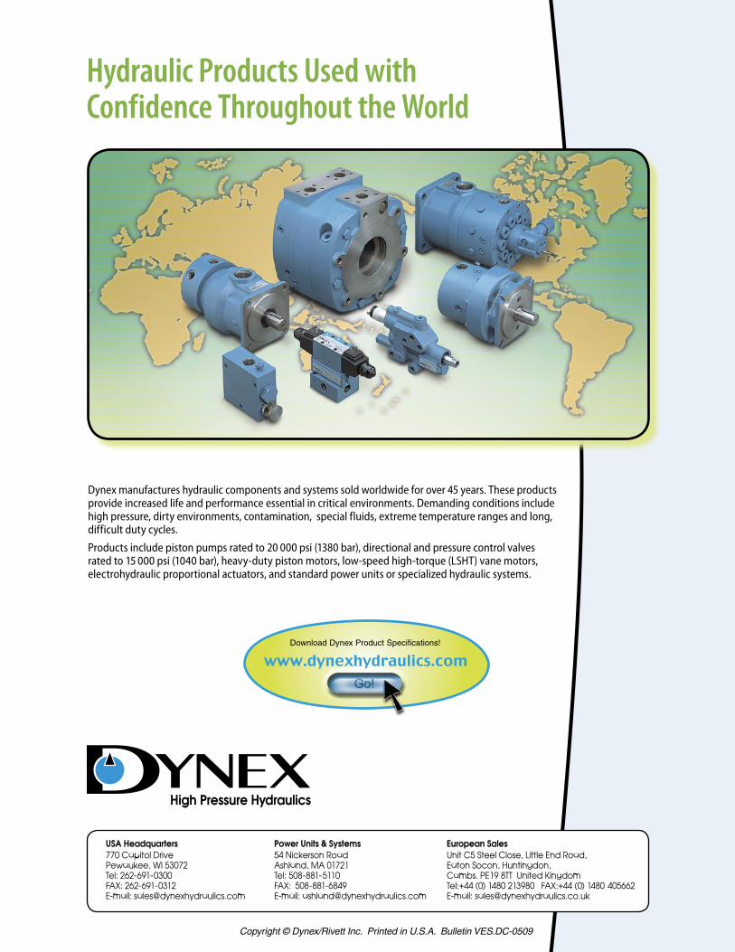
Copyright © Dynex/Rivett Inc. Printed in U.S.A. Bulletin VES.DC-0509
Hydraulic Products Used with Confidence Throughout the World
Dynex manufactures hydraulic components and systems sold worldwide for over 45 years. These products provide increased life and performance essential in critical environments. Demanding conditions include high pressure, dirty environments, contamination, special fluids, extreme temperature ranges and long, difficult duty cycles.
Products include piston pumps rated to 20 000 psi (1380 bar), directional and pressure control valves rated to 15 000 psi (1040 bar), heavy-duty piston motors, low-speed high-torque (LSHT) vane motors, electrohydraulic proportional actuators, and standard power units or specialized hydraulic systems.
Download Dynex Product Specifications!
European SalesUnit C5 Steel Close, Little End Road, Eaton Socon, Huntingdon, Cambs. PE19 8TT United KingdomTel:+44 (0) 1480 213980 FAX:+44 (0) 1480 405662 E-mail: [email protected]
USA Headquarters770 Capitol DrivePewaukee, WI 53072Tel: 262-691-0300FAX: 262-691-0312E-mail: [email protected]
Power Units & Systems54 Nickerson RoadAshland, MA 01721Tel: 508-881-5110FAX: 508-881-6849 E-mail: [email protected]