Dynamics of Prestressed Concrete Railway Bridges
81
Dynamics of Prestressed Concrete Railway Bridges by Sergio Ruiz Melendez B. Tech (Structural Engineering) 1998, U.P.V. Bilbao, Spain B. Tech (Industrial Engineering) 2000, U.A.X. Madrid, Spain SUBMITTED TO THE DEPARTMENT OF CIVIL AND ENVIRONMENTAL ENGINEERING IN PARTIAL FULFILLMENT OF THE REQUIREMENTS FOR THE DEGREE OF MASTER OF ENGINEERING IN CIVIL AND ENVIRONMENTALMASSACHUSETTS INSTITUTE ENGINEERING OF TECHNOLOGY at the JUNiiili ? i1 MASSACHUSETTS INSTITUTE OF TECHNOLOGY LIBRARIES June 2001 © 2001 Sergio Ruiz Melendez. All rights reserved. The author hereby grants to MIT permission to reproduce and to distribute publicly paper and electronic copies of this thesis document in whole or in part A utho r ............ ............................................................. .. Department of Civil and Environmental Engineering n r\ a Mav1 1h ,2001 C e rtifie d b y .................... .... ..... ..... ......... . .. ....... I........ ................ Cri b Jerome Connor Professor of Civil and Environmental Engineering Thesis Supervisor Accepted by ..................... Oral Buyukozturk Chairman, Department Committee on Graduate Students
Transcript of Dynamics of Prestressed Concrete Railway Bridges
Dynamics of Prestressed Concrete Railway Bridges
by
Sergio Ruiz Melendez
B. Tech (Structural Engineering) 1998, U.P.V. Bilbao, SpainB. Tech (Industrial Engineering) 2000, U.A.X. Madrid, Spain
SUBMITTED TO THE DEPARTMENT OF CIVIL AND ENVIRONMENTALENGINEERING IN PARTIAL FULFILLMENT OF THE REQUIREMENTS FOR
THE DEGREE OF
MASTER OF ENGINEERING IN CIVIL AND ENVIRONMENTALMASSACHUSETTS INSTITUTEENGINEERING OF TECHNOLOGY
at the JUNiiili ? i1
MASSACHUSETTS INSTITUTE OF TECHNOLOGY LIBRARIES
June 2001
© 2001 Sergio Ruiz Melendez. All rights reserved.
The author hereby grants to MIT permission to reproduce and to distributepublicly paper and electronic copies of this thesis document in whole or in part
A utho r ............ ............................................................. . .Department of Civil and Environmental Engineering
n r\ a Mav1 1h ,2001
C e rtifie d b y .................... .... ..... ..... ......... . . . ....... I........ ................Cri b Jerome Connor
Professor of Civil and Environmental EngineeringThesis Supervisor
Accepted by .....................Oral Buyukozturk
Chairman, Department Committee on Graduate Students

DYNAMICS OF PRESTRESSED CONCRETE RAILWAY BRIDGES
by
Sergio Ruiz Melendez
Submitted to the Department of Civil and Environmental Engineering on May 11, 2001in partial fulfillment of the requirements for the degree of
Master of Engineering in Civil and Environmental Engineering
Abstract
The purpose of this thesis is to evaluate the dynamic displacement effects of a
Prestressed concrete bridge while a high-velocity train is traveling along it.
High Speed Railways require a high linearity, with large radius of curvature on
curves and limited slope. In order to satisfy these requirements, large percentages of
the total projects have to be done with the rails lying on bridges, viaducts or just
elevated.
Prestressed concrete has been proved, from many projects constructed all over
the world for the last 20 years, to be one of the most effective structural design choices
in terms of economy, constructibility, maintainability and expected life cycle. Because of
it, this structural system will be the one to be used in order to perform the current study
on the effects that the dynamic loadings, from high-speed trains, would produce on such
bridge type structures.
Basic principles of prestressed concrete will be covered in order to be able to
perform the dynamic analysis as well as to determine the dynamic impact that the train
traveling along a bridge would produce on it by doing a motion based design.

Basic concepts of bridge dynamic analysis will also be covered. Since the
vehicle speed is the most important parameter influencing the dynamic stresses and
deflections, and because they generally increase with increasing speed, the analysis of
its effects on bridges is extremely important in order to be able to upgrade the
performance of the structures.
Once all the required concepts for the prestressed concrete beam dynamic
analysis have been reviewed a case study will be performed. Since the large
deflections caused by the dynamic load impact can increase environmental noise and
the track maintenance required and decrease the ride comfort quality for the
passengers, is the purpose of the above mentioned study to determine those
deflections at all times so that we may determine when, where, and why should we take
actions in order to limit them.
Thesis Supervisor: Jerome Connor
Title: Professor of Civil and Environmental Engineering

To Neretxo
DYNAMIC OF PRESTRESSED CONCRETE RAILWAY BRIDGES
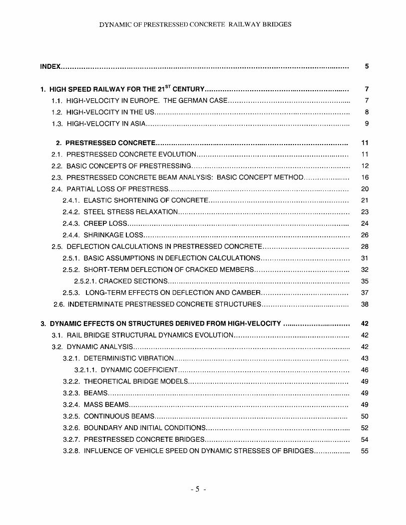
INDEX................................................................................................................................. 5
1. HIGH SPEED RAILW AY FOR THE 2 1ST CENTURY................................................................ 7
1.1. HIGH-VELOCITY IN EUROPE. THE GERMAN CASE...................................................... 7
1.2. HIGH-VELOCITY IN THE US........................................................................................ 8
1.3. HIGH-VELOCITY IN ASIA............................................................................................ 9
2. PRESTRESSED CONCRETE....................................................................................... 11
2.1. PRESTRESSED CONCRETE EVOLUTION................................................................... 11
2.2. BASIC CONCEPTS OF PRESTRESSING....................................................................... 12
2.3. PRESTRESSED CONCRETE BEAM ANALYSIS: BASIC CONCEPT METHOD..................... 16
2.4. PARTIAL LOSS OF PRESTRESS ................................................................................. 20
2.4.1. ELASTIC SHORTENING OF CONCRETE.............................................................. 21
2.4.2. STEEL STRESS RELAXATION............................................................................. 23
2.4.3. CREEP LOSS.................................................................................................... 24
2.4.4. SHRINKAGE LOSS............................................................................................. 26
2.5. DEFLECTION CALCULATIONS IN PRESTRESSED CONCRETE....................................... 28
2.5.1. BASIC ASSUMPTIONS IN DEFLECTION CALCULATIONS........................................ 31
2.5.2. SHORT-TERM DEFLECTION OF CRACKED MEMBERS........................................... 32
2.5.2.1. CRACKED SECTIONS................................................................................. 35
2.5.3. LONG-TERM EFFECTS ON DEFLECTION AND CAMBER....................................... 37
2.6. INDETERMINATE PRESTRESSED CONCRETE STRUCTURES........................................ 38
3. DYNAMIC EFFECTS ON STRUCTURES DERIVED FROM HIGH-VELOCITY ............................... 42
3.1. RAIL BRIDGE STRUCTURAL DYNAMICS EVOLUTION.................................................... 42
3.2. DYNAMIC ANALYSIS.................................................................................................. 42
3.2.1. DETERMINISTIC VIBRATION.............................................................................. 43
3.2.1.1. DYNAMIC COEFFICIENT............................................................................. 46
3.2.2. THEORETICAL BRIDGE MODELS........................................................................ 49
3 .2 .3 . B E A M S ............................................................................................................. 4 9
3.2.4. MASS BEAMS................................................................................................... 49
3.2.5. CONTINUOUS BEAMS...................................................................................... 50
3.2.6. BOUNDARY AND INITIAL CONDITIONS................................................................. 52
3.2.7. PRESTRESSED CONCRETE BRIDGES................................................................. 54
3.2.8. INFLUENCE OF VEHICLE SPEED ON DYNAMIC STRESSES OF BRIDGES................. 55
- 5 -
DYNAMIC OF PRESTRESSED CONCRETE RAILWAY BRIDGES
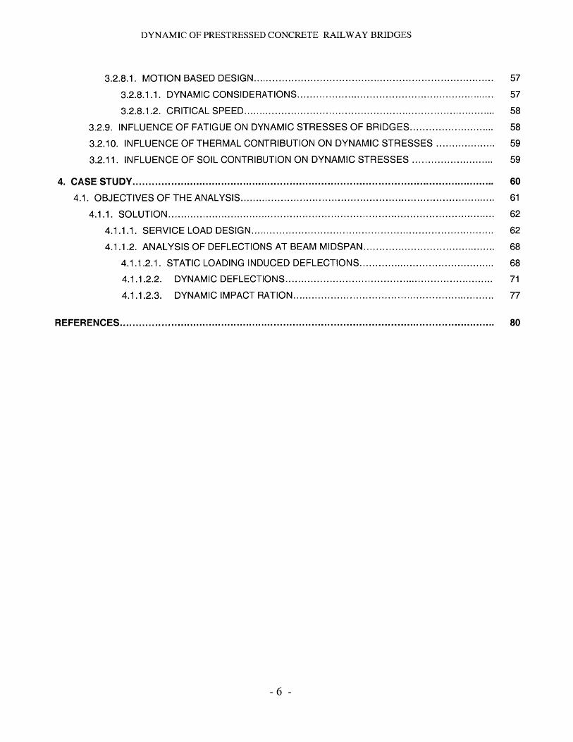
3.2.8.1. MOTION BASED DESIGN............................................................................ 57
3.2.8.1.1. DYNAMIC CONSIDERATIONS............................................................... 57
3.2.8.1.2. CRITICAL SPEED................................................................................ 58
3.2.9. INFLUENCE OF FATIGUE ON DYNAMIC STRESSES OF BRIDGES........................... 58
3.2.10. INFLUENCE OF THERMAL CONTRIBUTION ON DYNAMIC STRESSES ................... 59
3.2.11. INFLUENCE OF SOIL CONTRIBUTION ON DYNAMIC STRESSES .......................... 59
4. CASE STUDY................................................................................................................... 60
4.1. OBJECTIVES OF THE ANALYSIS................................................................................. 61
4 .1.1. S O L U T IO N ........................................................................................................ 62
4.1.1.1. SERVICE LOAD DESIGN............................................................................. 62
4.1.1.2. ANALYSIS OF DEFLECTIONS AT BEAM MIDSPAN.......................................... 68
4.1.1.2.1. STATIC LOADING INDUCED DEFLECTIONS........................................... 68
4.1.1.2.2. DYNAMIC DEFLECTIONS.................................................................. 71
4.1.1.2.3. DYNAMIC IMPACT RATION................................................................ 77
REFERENCES....................................................................................................................... 80
- 6 -
DYNAMIC OF PRESTRESSED CONCRETE RAILWAY BRIDGES
1. High Speed Railway for the 21st Century.
Hundreds of miles of high velocity railways have been constructed all over world
in the past 20 years, and many others are projected for a nearby future. The reason
why the transportation authorities are looking in this direction is the search of several
important purposes like the improvement the overcrowded traffic condition along the
areas they cover, the increase of the value of the land use and development, the
upgrade of the living quality and standard, and the acceleration of the economic
development, growth, etc.
Moreover this technologically advanced transportation system ables passenger
trains to reach speeds up to 250 km/h (155 mph). However it is expected that railway
traffic based on the principle of wheels rolling along rails has a maximum speed of 500
km/h (315 mph). Therefore, further development includes magnetically levitated
(MAGLEV) vehicles which will attain even higher speeds.
1.1. High-Velocity in Europe. The German case.
France, Italy, United Kingdom, Spain and Germany are some of the countries
that more invested in this technologically advanced transportation system in Europe in
the last 20 years.
In the German case, 250 km/h (155mph) passenger trains have been designed
with the result of maximum slopes of 12.5% minimum radius of 7,000 m.
We may appreciate the important role bridges play for this type of infrastructures
taking a look to the first two railways connecting Hannover with Wurzburg, of 327 km
and Manheim with Stuttgart, of 99 km, both crossing mountainous areas, and in which
-7 -
DYNAMIC OF PRESTRESSED CONCRETE RAILWAY BRIDGES
130 km of tunnels were built and 35 km were bridges, what represents an 8% of the
total.
In Germany, prestressed concrete has been chosen most of the times for the
construction of high-speed line bridges and viaducts because of its economy comparing
to its equivalent in steel for approximate spans. It was considered the possibility of
replacing the decks in a period of time between 80 and 150 years after construction by
removing them transversally, what made them to limit the span of the continuous
viaducts. In order to do this, they have often been using isostatic beams. The average
span used was 44 m and the maximum spans constructed were of 58 m. However, in
many cases, they have taken the aesthetical, structural and the constructibility
advantages of the continuous beam bridges. This advantages are between others
hiperstaticity, lower deformations, possibility of high quality construction by using the
bridge launching procedure, slimmer piles and decks that would make the structure to
be more integrated in the landscape. However, it will be described in much more detail
the advantages of both, simple span and continuous bridges, in terms of design and
constructibility.
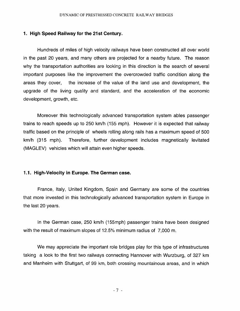
1.2. High-Velocity in the US.
Figure 1.1
-8 -
DYNAMIC OF PRESTRESSED CONCRETE RAILWAY BRIDGES
In the United States, after many decades of decline, the rail industry is gathering
steam again. Although this is mostly due to the increase on the construction of light-rail
networks in many metropolitan areas all over the country, it is also because of the many
high-speed rail lines already constructed, being constructed of just projected.
An example of an already constructed high-speed line is the one called Northeast
Corridor, which connects Boston with New York City, and that will continue to
Washington DC in a nearby future. Examples of projected high-velocity lines are the
one named Northwest Corridor, which will revamp track between Seattle, Vancouver
and British Columbia or the Alameda Corridor in California, connecting Los Angeles with
Long Beach.
Because the US has a high geographical diversity, the design and construction
options vary significantly for each case. Hence, the line connecting Boston with New
York only had to be adapted to the high-velocity circulation while in the Northwest
corridor, because it is a highly mountainous area, similar design and construction
options, like the ones taken in Germany, should be taken as the optimal in terms of
economy, constructibility and maintainability.
1.3. High-Velocity in Asia.
There are many high-speed rails already constructed in Asia, most of them in
Japan. One example of the magnitude of the projects done in Japan is the Kojima-
Sakaide Route, a 13.1 km series of bridges across the Inland Sea. The route connects
two of Japan's four main islands, Honshu and Shikoku. The route skips between five
islands and contains five double decker bridges. It took 20 years to design and nine
years to build and was opened on 1989.
-9 -
DYNAMIC OF PRESTRESSED CONCRETE RAILWAY BRIDGES
Design had to counter earthquake movements and typhoon winds. The upper deck
contains four highway lanes and the lower deck carries two high speed rail lines.
Moreover, design of the route required writing construction standards, as Japan had no
long-span bridges in the 1950s.
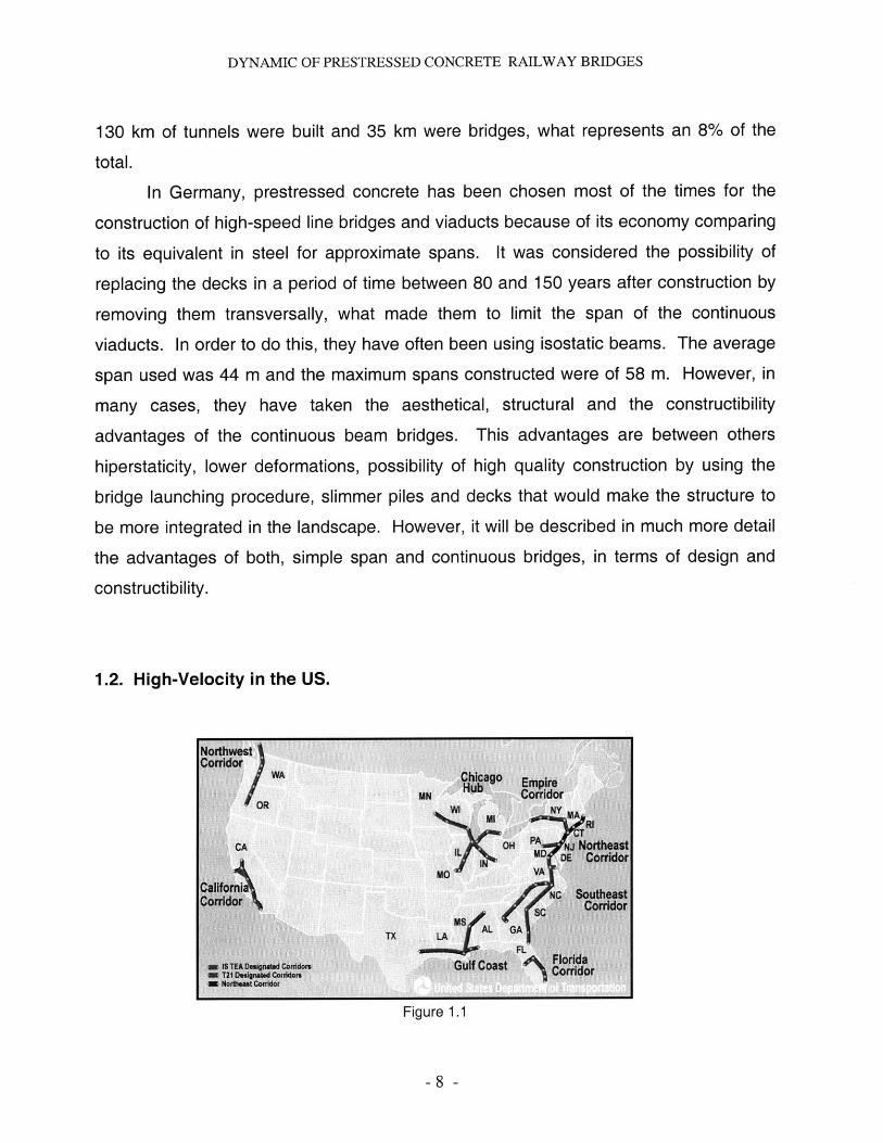
In Taiwan, the total length of the route of the high-speed railway being constructed
at the moment from Taipei, at the North of the country, to Kaohsiung, and industrial and
harbor city in the south, is of about 345 km. In order to save money for land and time
for construction, most parts of the route are on elevated railway. Simple-span beams
and three-equal-span continuous reinforced-concrete beams supported on piers are the
two most important standard design types used.
DepotfNorth Yard
Taipei
TaoyuanHsinchu
TaichungCentral YarChaiyi
TainanWorkshop HSR AligementSouth Yard Q HSR Station
Kaohslung ~Q Stabling YardQ Workshop
Figure 1.2
- 10 -
DYNAMIC OF PRESTRESSED CONCRETE RAILWAY BRIDGES
2. Prestressed Concrete.
2.1. Prestressed Concrete evolution.
Prestressed concrete began to acquire importance about right after the Second
World War. Perhaps the shortage of steel in Europe during the war had given it some
impetus, since much less steel is required for prestressed concrete than for
conventional types of construction. But it must also be realized that time was needed to
prove and improve the serviceability, economy, and safety of prestressed concrete as
well as to acquaint engineers and builders with a new method of design and
construction.
Although France and Belgium led the development of prestressed concrete,
England, Germany, Switzerland, Holland, Soviet Russia, and Italy quickly followed.
Since 1965, about 47% of all bridges built in Germany were of prestressed concrete.
Since the late 1960s and 1970s most medium-span bridges (100-300 ft, 30-90 m) and
many long-span bridges up to about 1000 ft (305 m) were built of prestressed concrete
in all parts of the world.
Prestressed concrete in the United States did not start until 1949 and since 1960,
the use of prestressed concrete bridges has become a standard practice. In many of
the states almost all bridges in the span range 60 to 120 ft (18-36 m) have been
constructed with prestressed concrete. Since the late 1970s, post-tensioned bridges of
medium spans (150-650 ft, 45-200 m) have gained momentum, in the form of
continuous or cantilever construction.
- 11 -
DYNAMIC OF PRESTRESSED CONCRETE RAILWAY BRIDGES
2.2. Basic concepts of prestressing
Prestressed concrete construction systems are those in which an internally or externally
compressive force p is induced on the structural element in order to maximize the
utilization of reinforced concrete, weak in tension but strong in compression. This
compressive force is applied through the use of stressed high-strength prestressing
wires or tendons prior to loading and because of this, the concrete section is generally
stressed only in compression under service and sometimes overload conditions.
It is important for the designer to fully understand the different prestressed
concrete design concepts so that he or she can proportion and design those structures
with intelligence and efficiency.
The Prestressing to transform concrete into an elastic material is a very extended
concept, which is the one to be considered at the case study, is explained as follows.
Prestressing to Transform Concrete into an Elastic Material. This concept
considers concrete as an elastic material and is probably still the most commonly
adopted viewpoint among engineers. Was Eugene Freyssinet who visualized
prestressed concrete as essentially concrete which is transformed from a brittle material
into an elastic one by a previous compression applied to it. Concrete which is weak in
tension and strong in compression is compressed (generally by steel under high
tension) so that the brittle concrete would be able to withstand tensile stresses. From
this concept the criterion of no tensile stresses was born. It is generally believed that if
there are no tensile stresses in the concrete, there can be no cracks, and the concrete
is no longer a brittle material but becomes an elastic material.
From this standpoint concrete is visualized as being subject to two systems of
forces: internal prestress and external load, with the tensile stresses due to the external
load counteracted by the compressive stresses due to the prestress. Similarly, the
12 -
DYNAMIC OF PRESTRESSED CONCRETE RAILWAY BRIDGES
cracking of concrete due to load is prevented or delayed by the precompression
produced by the tendons. So long as there are no cracks, the stresses, strains, and
deflections of the concrete due to the two systems of forces can be considered
separately and superimposed if necessary.
In prestressed concrete, high-tensile steel is used which will have to be
elongated a great deal before its strength is fully utilized. If the high-tensile steel is
simply buried in the concrete, as in ordinary concrete reinforcement, the surrounding
concrete will have to crack very seriously before the full strength of steel is developed.
Hence it is necessary to prestretch the steel with respect to the concrete. By
prestretching and anchoring the steel against the concrete, we produce desirable
stresses and stains in both materials: compressive stresses and strains in concrete, and
tensile stresses and stains in steel. This combined action permits the safe and
economical utilization of the two materials which cannot be achieved by simply burying
steel in the concrete as is done for ordinary reinforced concrete. In isolated instances,
medium-strength steel has been used as simple reinforcement without prestressing,
and the steel was specially corrugated for bond, in order to distribute the cracks. This
process avoids the expenses for prestretching and anchoring high-tensile steel but does
not have the desirable effects of precompressing the concrete and of controlling the
deflections.
From this point of view, prestressed concrete is no longer a strange type of
design. It is rather an extension and modification of the applications of reinforced
concrete to include steels of higher strength. Because of this, prestressed concrete
cannot perform miracles beyond the capacity of the strength of its materials. Although
much ingenuity can be exercised in the proper and economic design of prestressed-
concrete structures, there is absolutely no magic method to avoid the eventual
necessity of carrying an external moment by an internal couple. And that internal
- 13 -
DYNAMIC OF PRESTRESSED CONCRETE RAILWAY BRIDGES
resisting couple must be supplied by the steel in tension and the concrete in
compression, whether it be prestressed or reinforced concrete.
The prestressing force P that satisfies the particular conditions of geometry and
loading of a given element is determined from the principles of mechanics and of stress-
strain relationships. Sometimes simplification is necessary, as when a prestressed
beam is assumed to be homogeneous and elastic. A comprehensive treatment of the
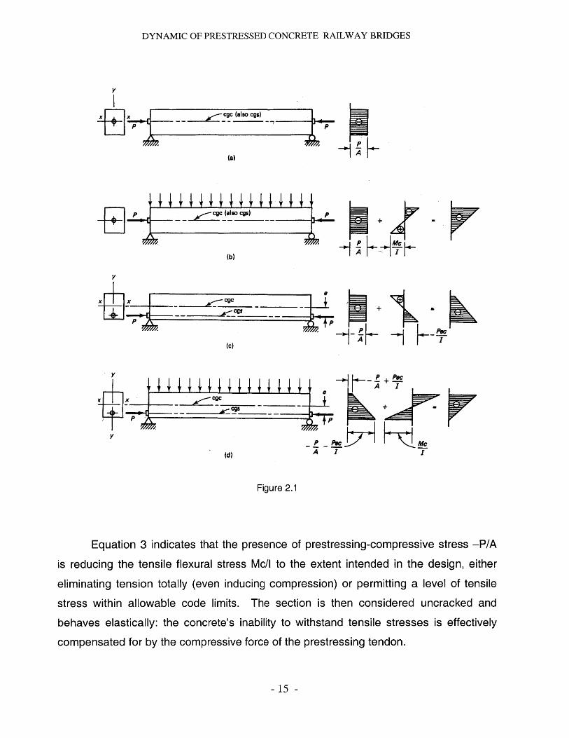
subject of prestressed concrete may be found in Equation 1. Consider, then, a simply
supported rectangular beam subjected to a concentric prestressing force P, as shown in
Figure 2.1. The compressive stress on the beam cross section is uniform and has an
intensity
Pf (1)
where A, = b -h is the cross-sectional area of a beam section of width b and total depth
h. A minus sign is used for compression and a plus sign for tension throughout the text.
Also, bending moments are drawn on the tensile side of the member. If external
transverse loads are applied to the beam, causing a maximum moment M at midspan,
the resulting stress becomes
f t PMC (2)AlIP Mc
fb P+ MC (3)A I,
where
= stress at the top fibers
f = stress at the bottom fibers
c = h for the rectangular section
/= gross moment of inertia of the section (bh3/1 2 in this case)
- 14 -
DYNAMIC OF PRESTRESSED CONCRETE RAILWAY BRIDGES
X cgc (also cgs)
(a)
cgc (also cgs)
(b) P
V
F cg
g-- 0 r- cgs__ __
(d)A II
Figure 2.1
Equation 3 indicates that the presence of prestressing-compressive stress -P/A
is reducing the tensile flexural stress Mc/l to the extent intended in the design, either
eliminating tension totally (even inducing compression) or permitting a level of tensile
stress within allowable code limits. The section is then considered uncracked and
behaves elastically: the concrete's inability to withstand tensile stresses is effectively
compensated for by the compressive force of the prestressing tendon.
- 15 -
DYNAMIC OF PRESTRESSED CONCRETE RAILWAY BRIDGES
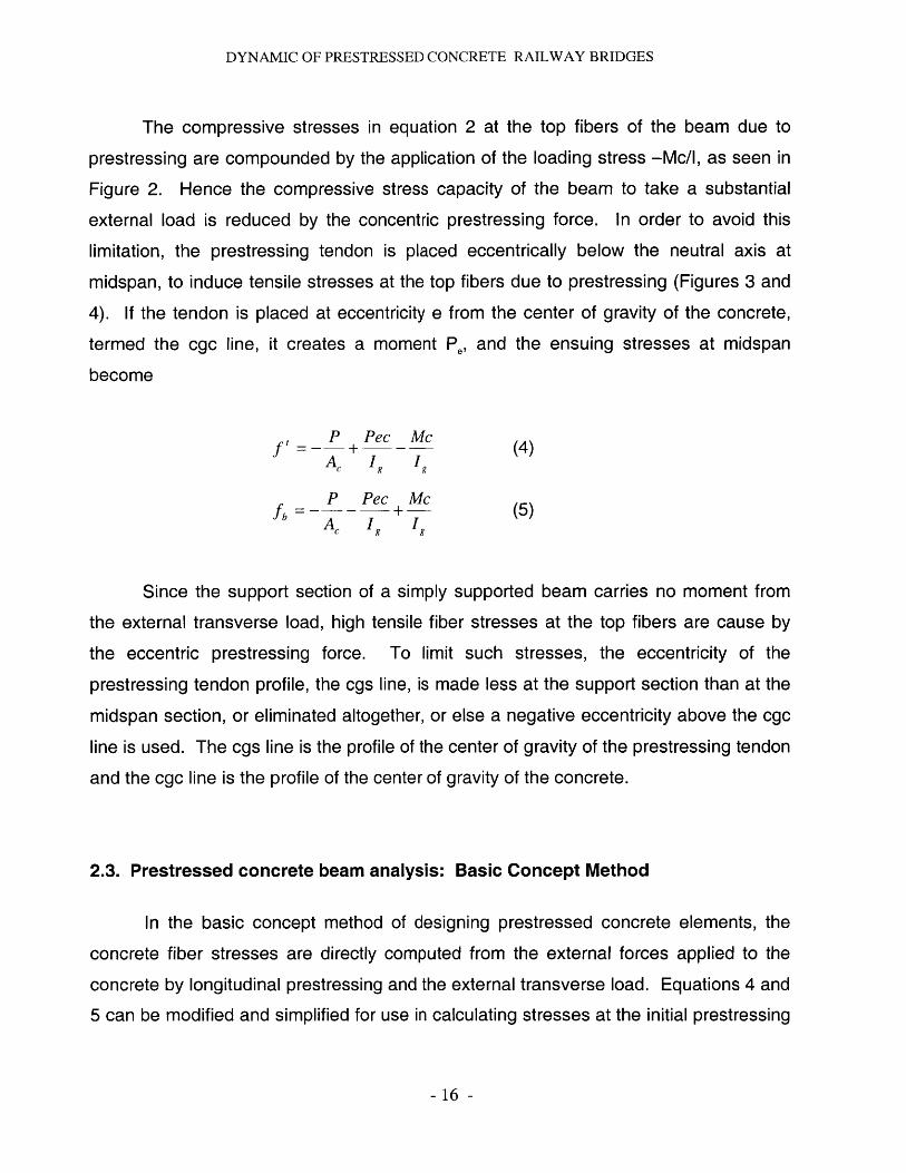
The compressive stresses in equation 2 at the top fibers of the beam due to
prestressing are compounded by the application of the loading stress -Mc/l, as seen in
Figure 2. Hence the compressive stress capacity of the beam to take a substantial
external load is reduced by the concentric prestressing force. In order to avoid this
limitation, the prestressing tendon is placed eccentrically below the neutral axis at
midspan, to induce tensile stresses at the top fibers due to prestressing (Figures 3 and
4). If the tendon is placed at eccentricity e from the center of gravity of the concrete,
termed the cgc line, it creates a moment Pe, and the ensuing stresses at midspan
become
P Pec Mc (4)
AC Ig Ig
_ P Pec Mc (5)
Since the support section of a simply supported beam carries no moment from
the external transverse load, high tensile fiber stresses at the top fibers are cause by
the eccentric prestressing force. To limit such stresses, the eccentricity of the
prestressing tendon profile, the cgs line, is made less at the support section than at the
midspan section, or eliminated altogether, or else a negative eccentricity above the cgc
line is used. The cgs line is the profile of the center of gravity of the prestressing tendon
and the cgc line is the profile of the center of gravity of the concrete.
2.3. Prestressed concrete beam analysis: Basic Concept Method
In the basic concept method of designing prestressed concrete elements, the
concrete fiber stresses are directly computed from the external forces applied to the
concrete by longitudinal prestressing and the external transverse load. Equations 4 and
5 can be modified and simplified for use in calculating stresses at the initial prestressing
- 16 -
DYNAMIC OF PRESTRESSED CONCRETE RAILWAY BRIDGES
stage and at service load levels. If P, is the initial prestressing force before stress
losses, and P. is the effective prestressing force after losses, then
can be defined as the residual prestress factor. Substituting r2 for l/A, in Equations 4
and 5, where r is the radius of gyration of the gross section, the expressions for stress
can be rewritten as follows:
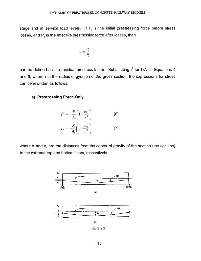
a) Prestressing Force Only
f' P - ec'AC r 2
Pi= 1- ~
(6)
(7)
where c, and cb are the distances from the center of
to the extreme top and bottom fibers, respectively.
gravity of the section (the cgc line)
- cg
(a)
6*
~A 1Y. - cTs
-v(b)
Figure 2.2
- 17 -
DYNAMIC OF PRESTRESSED CONCRETE RAILWAY BRIDGES
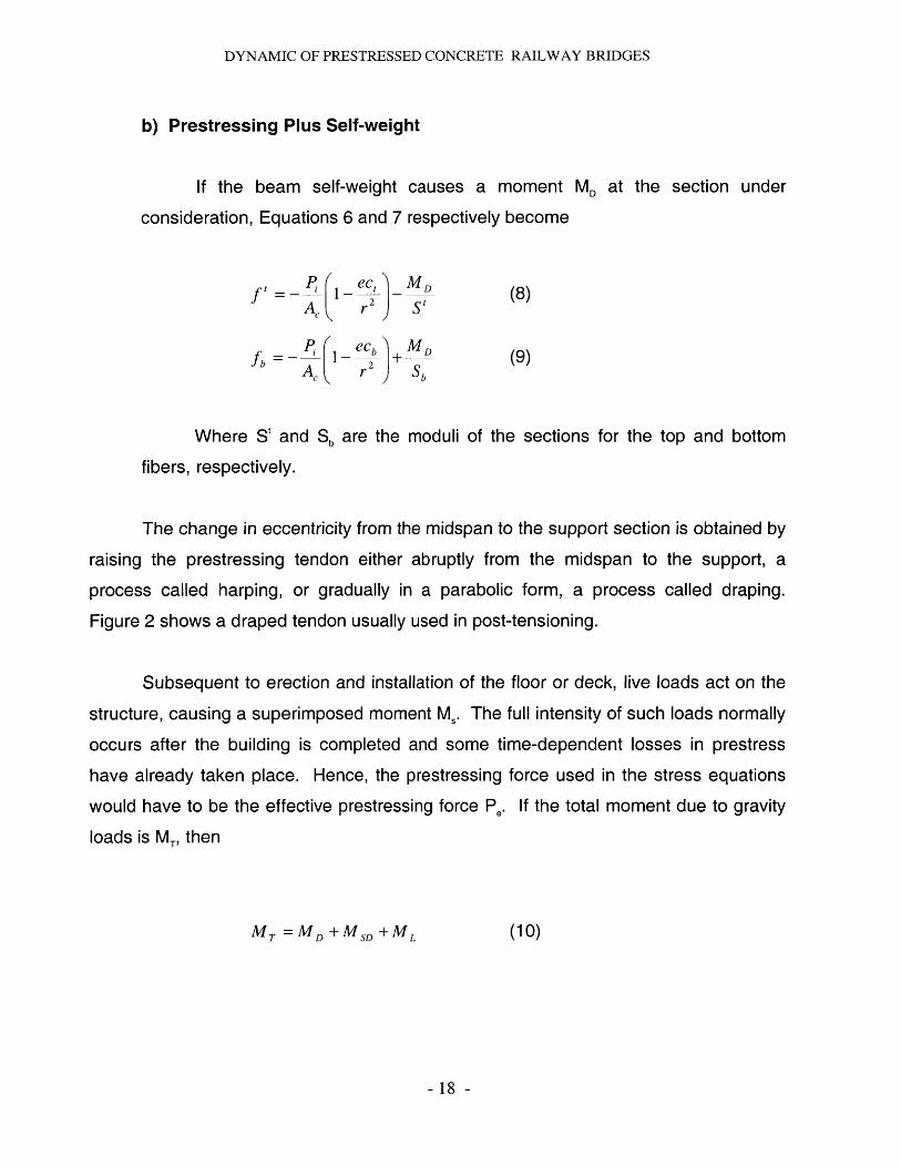
b) Prestressing Plus Self-weight
If the beam self-weight causes a moment MD at the section under
consideration, Equations 6 and 7 respectively become
ft (8 )1 ec, M,Ac r 2 S t
Pi= (1_ e+ M1(9)fb A, (2
Where St and Sb are the moduli of the sections for the top and bottom
fibers, respectively.
The change in eccentricity from the midspan to the support section is obtained by
raising the prestressing tendon either abruptly from the midspan to the support, a
process called harping, or gradually in a parabolic form, a process called draping.
Figure 2 shows a draped tendon usually used in post-tensioning.
Subsequent to erection and installation of the floor or deck, live loads act on the
structure, causing a superimposed moment M.. The full intensity of such loads normally
occurs after the building is completed and some time-dependent losses in prestress
have already taken place. Hence, the prestressing force used in the stress equations
would have to be the effective prestressing force P,. If the total moment due to gravity
loads is MT, then
MT = MD +MSD +ML (10)
- 18 -
DYNAMIC OF PRESTRESSED CONCRETE RAILWAY BRIDGES
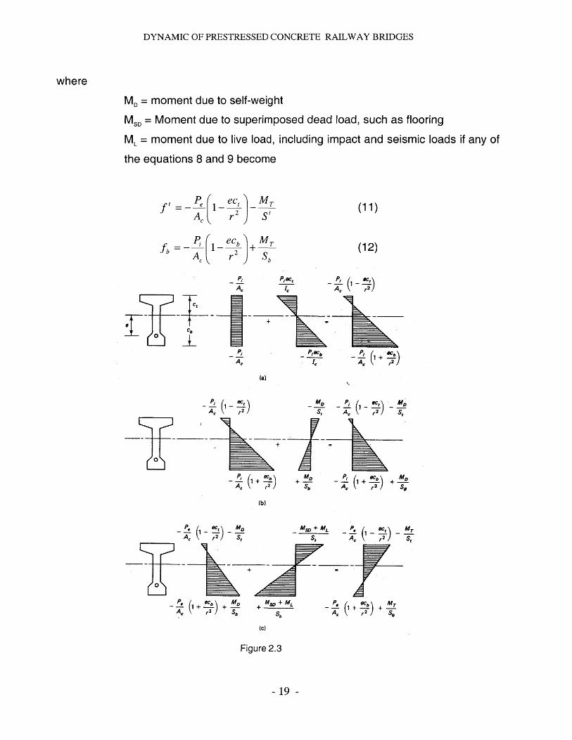
where
MD = moment due to self-weight
MSD = Moment due to superimposed dead load, such as flooring
ML = moment due to live load, including impact and seismic loads if any of
the equations 8 and 9 become
f ( 11ec,
M,A C r2 S I
_ Pf=- (12)
P1At
CbA I
0
'pc 2A rA19r)
+1
Piacb P
A\ r2
(a)
- -_ 1 -ec - M,r2 A r 2) s,
- 1+ + MD Pi +'4 + 'A \ r2 sb T,\ r2 SA
D
(b)
MT
St
- 19 -
- M+ML P.-(es,+A,S S, A 62
0+T
-f (1+.b) + + Ms,+M -+{ (+b) +±MA,\ r2; oS , r2;Sb Sb +~ r) S6
(c)
Figure 2.3
y
1c + M
r 2 )
DYNAMIC OF PRESTRESSED CONCRETE RAILWAY BRIDGES
Some typical elastic concrete stress distributions at the critical section of a
prestressed flanged section are shown in Figure 4. The tensile stress in the concrete in
part c permitted at the extreme fibers of the section cannot exceed the maximum
permissible in the code, e.g. f, = 64 f in the ACI code. If it is exceeded, bonded non-
prestressed reinforcement proportioned to resist the total tensile force has to be
provided to control cracking at service loads.
2.4. Partial Loss of prestress
Prestressing force applied to the concrete elements undergoes a progressive
process of reduction over a period of approximately five years. For this reason it is
important to determine the level of the prestressing force at each loading stage, form
the stage of transfer of the prestressing force to the concrete, to the various stages of
prestressing available at service load, up to the ultimate.
The reduction in the prestressing force may happen immediately or time
dependant. The first ones corresponds to an immediate elastic loss during the
fabrication or construction process, including elastic shortening of the concrete,
anchorage losses, and frictional losses. The second ones corresponds to the losses
due to creep, shrinkage, and the ones originated by temperature effects and steel
relaxation. All these losses may be determined at the service-load limit state of stress
in the prestressed concrete element.
It is not feasible to determine with exactitude the magnitude of the mentioned
above prestress losses, specially the time dependent ones. However, a very high
degree of refinement of loss estimation is not desirable, because of the multiplicity of
the many factors affecting the estimate.
- 20 -
DYNAMIC OF PRESTRESSED CONCRETE RAILWAY BRIDGES
For the case of post-tensioned members the total loss in prestressed can be
calculated as follows:
AfPT = AfpA +AfpF + AfpES + ApR + AfpCR +AfpSH
where AfpES is applicable only when tendons are jacked sequentially, and not
simultaneously.
In the
transfer time
post-tensioned case, computation of relaxation loss starts between the
t, = ttr and the end of the time interval t2 under consideration. Hence
= - AfP - AfPfpi = pi fpA fpF
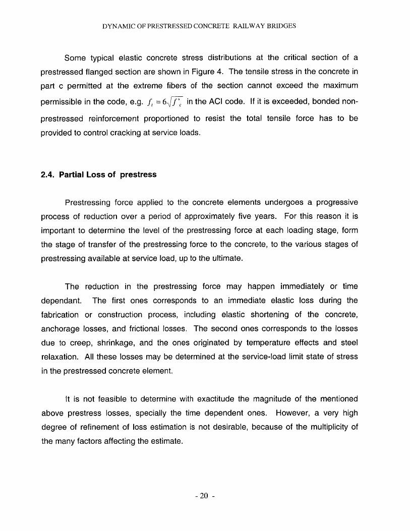
2.4.1. Elastic shortening of concrete (ES)
Concrete shortens when a prestressing force is applied. As the tendons that are
bonded to the adjacent concrete simultaneously shorten, they lose part of the
prestressing force that they carry.
The compressive force imposed on the beam by the tendon result in the
longitudinal shortening of the beam. The unit shortening in concrete isEES = A ES IL, so
EES fc _ j:Ec AcEc
(13)
Since the prestressing tendon suffers the same magnitude shortening,
-21 -
DYNAMIC OF PRESTRESSED CONCRETE RAILWAY BRIDGES
ERPAfpES =EEES
ACEC
nP
As
If the tendon has an eccentricity e at the beam midspan and the self-weight moment MD
is taken into account, the stress the concrete undergoes at the midspan section at the
level of the prestressing steel becomes
P e2 M efcs = ' 1+,
(16)
where Pi has a lower value after transfer of prestress. The small reduction in the value
of Pi to P, occurs because the force in the prestressing steel immediately after transfer
is less than the initial jacking prestress force PJ. However, since it is difficult to
accurately determine the reduce value of P,, and since observations indicate that the
reduction is only a few percentage points, it is possible to use the initial valued of P,
before transfer in Equations 13 to 16, or reduce it by about 10 percent for refinement if
desired.
Tendon
r ~ : ~ 6 4 ~__Q
L
-r
Figure 2.4
- 22 -
(14)
(15)
do
. '.2
a|
Ac
I
DYNAMIC OF PRESTRESSED CONCRETE RAILWAY BRIDGES
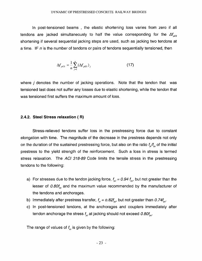
In post-tensioned beams , the elastic shortening loss varies from zero if all
tendons are jacked simultaneously to half the value corresponding for the AfpES
shortening if several sequential jacking steps are used, such as jacking two tendons at
a time. IF n is the number of tendons or pairs of tendons sequentially tensioned, then
=f~ I-L(fPn ) (17)Af PES I pES jnj=
where j denotes the number of jacking operations. Note that the tendon that was
tensioned last does not suffer any losses due to elastic shortening, while the tendon that
was tensioned first suffers the maximum amount of loss.
2.4.2. Steel Stress relaxation ( R)
Stress-relieved tendons suffer loss in the prestressing force due to constant
elongation with time. The magnitude of the decrease in the prestress depends not only
on the duration of the sustained prestressing force, but also on the ratio f,/f, of the initial
prestress to the yield strength of the reinforcement. Such a loss in stress is termed
stress relaxation. The ACI 318-89 Code limits the tensile stress in the prestressing
tendons to the following:
a) For stresses due to the tendon jacking force, fP = 0.94 f,, but not greater than the
lesser of 0.80f,, and the maximum value recommended by the manufacturer of
the tendons and anchorages.
b) Immediately after prestress transfer, fp, = o. 82f,,, but not greater than 0. 74f,.
c) In post-tensioned tendons, at the anchorages and couplers immediately after
tendon anchorage the stress fP at jacking should not exceed 0.80f, .
The range of values of f,, is given by the following:
- 23 -
DYNAMIC OF PRESTRESSED CONCRETE RAILWAY BRIDGES
Prestressing bars: f,, = 0.80f,
Stress-relieved tendons: f,, = 0.85fp,
Low-relaxation tendons: f, = 0.90fp
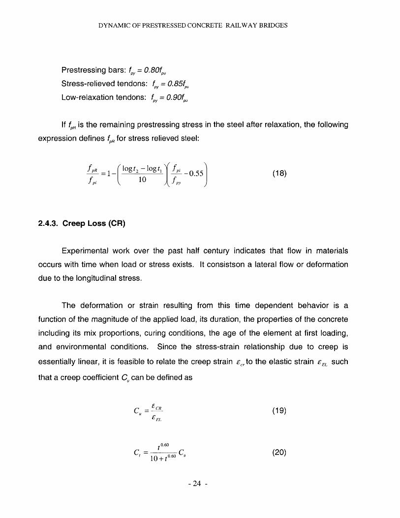
1f fR is the remaining prestressing stress in the steel after relaxation, the following
expression defines f, for stress relieved steel:
=1- -0.55 (18)fpi 10 fpy
2.4.3. Creep Loss (CR)
Experimental work over the past half century indicates that flow in materials
occurs with time when load or stress exists. It consistson a lateral flow or deformation
due to the longitudinal stress.
The deformation or strain resulting from this time dependent behavior is a
function of the magnitude of the applied load, its duration, the properties of the concrete
including its mix proportions, curing conditions, the age of the element at first loading,
and environmental conditions. Since the stress-strain relationship due to creep is
essentially linear, it is feasible to relate the creep strain Ecto the elastic strain EEL such
that a creep coefficient C, can be defined as
C, = CR (19)EEL
0 .60
10 + t0 0 ()
- 24 -
DYNAMIC OF PRESTRESSED CONCRETE RAILWAY BRIDGES
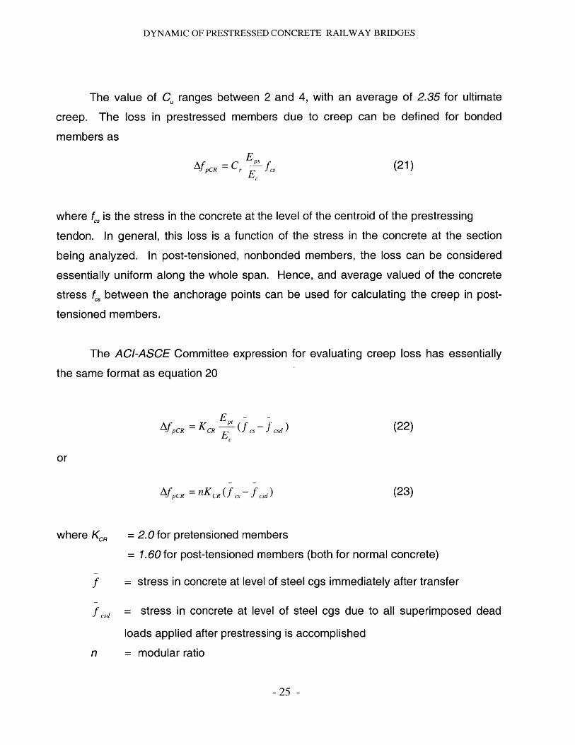
The value of C, ranges between 2 and 4, with an average of 2.35 for ultimate
creep. The loss in prestressed members due to creep can be defined for bonded
members as
AfPCR r cs (21)
where f., is the stress in the concrete at the level of the centroid of the prestressing
tendon. In general, this loss is a function of the stress in the concrete at the section
being analyzed. In post-tensioned, nonbonded members, the loss can be considered
essentially uniform along the whole span. Hence, and average valued of the concrete
stress f., between the anchorage points can be used for calculating the creep in post-
tensioned members.
The ACI-ASCE Committee expression for evaluating creep loss has essentially
the same format as equation 20
AfP CR = KCR pt cs csdEC
or
Af CR = nKCR(fes-f sd) (23)
where KCR = 2.0 for pretensioned members
= 1.60 for post-tensioned members (both for normal concrete)
f = stress in concrete at level of steel cgs immediately after transfer
f cd = stress in concrete at level of steel cgs due to all superimposed dead
loads applied after prestressing is accomplished
n = modular ratio
- 25 -
DYNAMIC OF PRESTRESSED CONCRETE RAILWAY BRIDGES
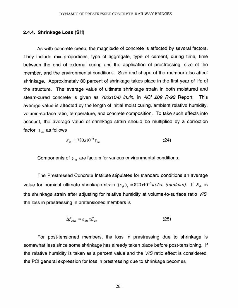
2.4.4. Shrinkage Loss (SH)
As with concrete creep, the magnitude of concrete is affected by several factors.
They include mix proportions, type of aggregate, type of cement, curing time, time
between the end of external curing and the application of prestressing, size of the
member, and the environmental conditions. Size and shape of the member also affect
shrinkage. Approximately 80 percent of shrinkage takes place in the first year of life of
the structure. The average value of ultimate shrinkage strain in both moistured and
steam-cured concrete is given as 780x10-6 in./in. in ACI 209 R-92 Report. This
average value is affected by the length of initial moist curing, ambient relative humidity,
volume-surface ratio, temperature, and concrete composition. To take such effects into
account, the average value of shrinkage strain should be multiplied by a correction
factor Ysh as follows
Esh =78Ox10 6 h (24)
Components of ,sh are factors for various environmental conditions.
The Prestressed Concrete Institute stipulates for standard conditions an average
value for nominal ultimate shrinkage strain (esh ) 820x 0- 6 iflin. (mm/mm). if 8sh is
the shrinkage strain after adjusting for relative humidity at volume-to-surface ratio VIS,
the loss in prestressing in pretensioned members is
AfPSH = e SHxEPS (25)
For post-tensioned members, the loss in prestressing due to shrinkage is
somewhat less since some shrinkage has already taken place before post-tensioning. If
the relative humidity is taken as a percent value and the V/S ratio effect is considered,
the PCI general expression for loss in prestressing due to shrinkage becomes
- 26 -

DYNAMIC OF PRESTRESSED CONCRETE RAILWAY BRIDGES
Af PSH = 8.2A - 6 KSHEPj 1- 0.06 V (100 - RH)
where KSH = 1.0 for pretensioned members. The table 1 gives the
for post-tensioned members.
values of KSH
time 1 3 5 7 10 20 30 60
Ksh 0.92 0.85 0.80 0.77 0.73 0.64 0.58 0.45
Table 1
Adjustment of shrinkage losses for standard conditions as a function of time t in
days after seven days for moist curing and three days for steam curing can be obtained
from the following expressions
a) Moist curing, after seven days
(Esh,)t = t35t +35
(27)
where (Eh),, is the ultimate shrinkage strain, t - time in days after shrinkage is
considered.
b) Steam curing, after one to three days
(Fsh )t = t (Csh)Ut + 55
(28)
It should be noted that significant variations occur in the creep and shrinkage
values due to variations in the properties of the constituent materials form the various
sources, even if the products are plant-produced such as pretensioned beams. Hence
- 27 -
(26)
DYNAMIC OF PRESTRESSED CONCRETE RAILWAY BRIDGES
it is recommended that information for actual tests be obtained especially on
manufactured products, large span-to-depth ratio cases and/or if loading is unusually
heavy, like may be the present case of study.
2.5. Deflection calculations in prestressed concrete
Deflection and cracking behavior are very important factors in the design of
prestressed concrete members. Prestressed concrete elements are typically more
slender than their counterparts in reinforced concrete, and their behavior more affected
by flexural cracking, makes it more critical to control their deflection and cracking.
Before cracking, the deflections of prestressed-concrete beams can be predicted with
greater precision than that of reinforced-concrete beams. Under working loads,
prestressed-concrete beams do not crack; reinforced ones do.
For a typical beam, application of prestress force will produce upward camber. The
effect of concrete shrinkage, creep, and steel relaxation is gradually to reduce the
camber produced by the initial force as that force is diminished. However, the creep
effect is twofold. Although it produces loss of prestress force, tending to reduce the
camber, creep strains in the concrete usually increase the negative curvature
associated with prestress and, hence, increase the camber. Either of these time-
dependent effects may predominate, depending on the details of the design and the
material properties.
Dead and live loads usually produce downward deflections that superimpose on the
upward deflection due to prestress. In the case of sustained loads, these too are time-
dependent because of concrete creep.
By prestressing, it is possible to control deflections to a remarkable degree. In fact,
it is only through deflection control that the high span-to-depth ratios typical of
-28 -
DYNAMIC OF PRESTRESSED CONCRETE RAILWAY BRIDGES
prestressed concrete can be achieved. A prestressed beam of a given cross section is
considerably stiffer than a reinforced concrete beam of the same section, because
cracking is reduced or eliminated by prestressing. Thus, all of nearly all of the cross
section contributes to the moment of inertia and the flexural rigidity.
The primary design involves proportioning the structural member for the limit state
of flexural stresses at service load and for limit states of failure in flexure, shear, and
torsion, including anchorage development strength. Such a design can only become
complete if the magnitudes of long-term deflection, camber (reverse deflection), and
crack width are determined to be within allowable serviceability values.
As usually encountered for any concrete member, two difficulties still stand in the
way when we wish to get an accurate prediction of the deflections. First, it is difficult to
determine the value of E, within an accuracy of 10% or even 20%. Besides, the value of
E, varies for different stress levels and changes with the age of concrete. The second
difficulty lies in estimating the effect of creep on deflections. The value of creep
coefficient as well as the duration and magnitude of the applied load cannot always be
known in advance. However, for practical purposes, an accuracy of 10% or 20% is
often sufficient, and that can be attained if all factors are carefully considered.
Deflections of prestressed beams differ from those of ordinary reinforced beams in
the effect of prestress.
If the prestress force is accurately known, if the materials are stressed only within
their elastic ranges, and if the concrete remains uncracked, then the calculation of
deflection of a prestressed flexural member presents no special difficulty.
The difficulty of predicting very accurately the total long-term prestress losses
makes it more difficult in partially prestressed concrete systems, where limited cracking
is allowed through the use of additional nonprestressed reinforcement. Creep strain in
- 29 -
DYNAMIC OF PRESTRESSED CONCRETE RAILWAY BRIDGES
the concrete increases camber, as it causes a negative increase in curvature which is
usually more dominant than the decrease produced by the decrease in prestress losses
due to creep, shrinkage, and stress relaxation. A best estimate of camber increase
should be based on accumulated experience, span-to-depth ratio code limitations, and
a correct choice of the modulus EX of the concrete. Calculation of the moment-curvature
relationships at the major incremental stages of loading up to the limit state at failure
would also assist in giving a more accurate evaluation of the stress-related load
deflection of the structural element.
The cracking aspect of serviceability behavior in prestressed concrete is also
critical. Allowance for limited cracking in "partial prestressing" through the additional
use of nonprestressed steel is prevalent. Because of the high stress levels in the
prestressing steel, corrosion due to cracking can become detrimental to the service life
of the structure.
Partial prestressing consists on subjecting the beam to an intermediate solution
between fully prestressed and reinforced concrete. Although full prestressing offers the
possibility of complete elimination of cracks at full service load, it may at the same time
produce members with objectionably large camber, or negative deflection, at more
typical loads less than the full value. A smaller amount of prestress force may produce
improved deflection characteristics at load stages of interest. While cracks will usually
form in partially prestressed beams should the specified full service load be applied
these cracks are small and will close completely when the load is reduced.
In addition to improved deflection characteristics, partial prestressing may result in
significant economy by reducing the amount of prestressed reinforcement and by
permitting the use of cross-section configurations with certain practical advantages
compared with those required by full prestressing.
- 30 -

DYNAMIC OF PRESTRESSED CONCRETE RAILWAY BRIDGES
Even though the amount of prestress force may be reduced through use of partial
prestressing, a beam must still have an adequate factor of safety against failure. This
will often require the addition of ordinary reinforcing bars in the tension zone.
Alternatives are to provide the total steel area needed for strength by high strength
tendons, but to stress those tendons to less than their full permitted value, or to leave
some of the strands unstressed.
2.5.1. Basic assumptions in deflection calculations:
Deflection calculations can be made either from the moment diagrams of the
prestressing force and the external transverse loading, or form the moment-curvature
relationships. In either case, the following basic assumptions have to be made:
1. The concrete gross cross-sectional area is accurate enough to compute the
moment of inertia except when refined computations are necessary.
2. The modulus of concrete EC = 33w"5 f'; , where the value of f' corresponds to
the cylinder compressive strength of concrete at the age at which Ec is to be
evaluated.
3. The principle of superposition applies in calculating deflections due to transverse
load and camber due to prestressing.
4. All computations of deflection can be based on the center of gravity of the
prestressing strands (cgs), where the strands are treated as a single tendon.
5. Deflections due to shear deformations are disregarded.
6. Sections can be treated as totally elastic up to the decompression load.
Thereafter the cracked moment of inertia Icr can give a more accurate
determination of deflection and camber.
-31 -
DYNAMIC OF PRESTRESSED CONCRETE RAILWAY BRIDGES
2.5.2. Short-term (instantaneous) deflection of cracked members
Short-term deflections in prestressed concrete members are calculated on the
assumption that the sections are homogeneous, isotropic, and elastic. Such an
assumption is an approximation of actual behavior, particularly that the modulus Ec of
concrete varies with the age of the concrete and the moment of inertia varies with the
stage of loading, i.e., whether the section is uncracked or cracked.
Ideally, the load-deflection relationship is trilinear. The three regions prior to
rupture are:
Region /. Precracking stage, where a structural member is crack fee.
Region /. Postcracking stage, where the structural member develops acceptable
controlled cracking in both distribution and width.
Region ///. Postserviceability cracking stage, where the stress in the tensile
reinforcement reaches the limit state of yielding.
At the precracking region the segment of the load-deflection curve is essentially a
straight line defining full elastic behavior. The maximum tensile stress in the beam in
this region is less than its tensile strength in flexure, i.e., it is less than the modulus of
rupture f, of concrete. The flexural stiffness El of the beam can be estimated using
Young's modulus E, of concrete and the moment of inertia of the uncracked concrete
cross section.
The value of E. can be estimated using the ACI empirical expression
EC = 33w" ' (29)
or
EC = 57,000 f'; for normal-weight concrete (30)
-32 -
DYNAMIC OF PRESTRESSED CONCRETE RAILWAY BRIDGES
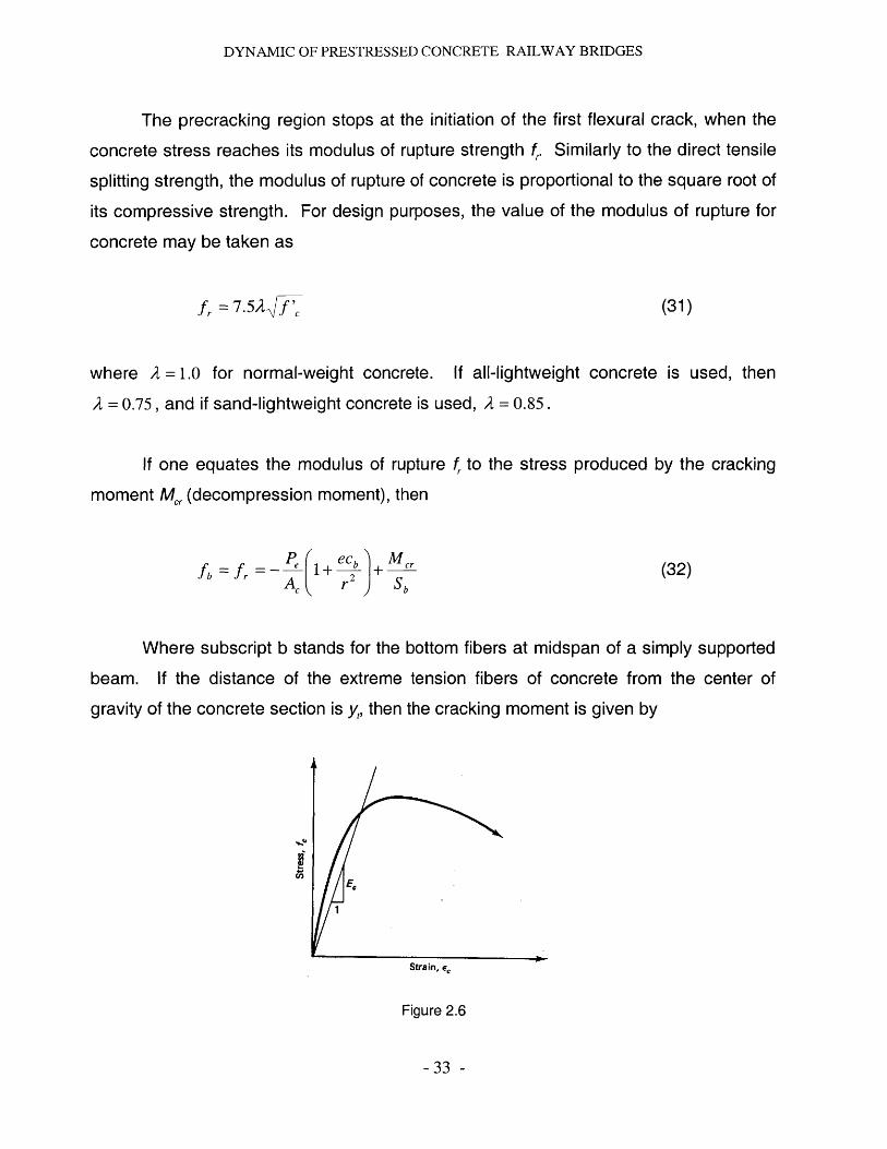
The precracking region stops at the initiation of the first flexural crack, when the
concrete stress reaches its modulus of rupture strength f, Similarly to the direct tensile
splitting strength, the modulus of rupture of concrete is proportional to the square root of
its compressive strength. For design purposes, the value of the modulus of rupture for
concrete may be taken as
f, = 7.52f (31)
where A = 1.0 for normal-weight concrete. If all-lightweight concrete is used, then
A = 0.75, and if sand-lightweight concrete is used, A = 0.85.
If one equates the modulus of rupture fr to the stress produced by the cracking
moment M, (decompression moment), then
fb = fr = P(+ejJMcr (32)Ac r 2 Sb
Where subscript b stands for the bottom fibers at midspan of a simply supported
beam. If the distance of the extreme tension fibers of concrete from the center of
gravity of the concrete section is y,, then the cracking moment is given by
E,
Strain, e,
Figure 2.6
- 33 -

DYNAMIC OF PRESTRESSED CONCRETE RAILWAY BRIDGES
f'c (33)Mc,. = 9 [p (1+b + 7.5A f (3y, AC r
Mcr = SL7.5 { + K 1 )+ 1 (34)AC r2
when S, = section modulus at the bottom fibers. More conservatively, from the equation
shown below, the cracking moment due to that portion of the applied live load that
causes cracking is
Mcr =S[7.5A + fc+fcefd (35)
where
fce = compressive stress at the center of gravity of concrete section due to
effective prestress only after losses when tensile stress is cause by applied
external load
f= concrete stress at extreme tensile fibers due to unfactored dead load when
tensile stresses and cracking are caused by the external load.
Equation 35 can be transformed to the PCI format giving identical results:
M =1- ft fr (36)Ma fL
where
Ma = maximum service unfactored live load moment
fe = final calculated total service load concrete stress in the member
f, = modulus of rupture
fL = service live load concrete stress in the member
- 34 -
DYNAMIC OF PRESTRESSED CONCRETE RAILWAY BRIDGES
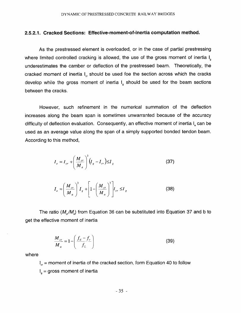
2.5.2.1. Cracked Sections: Effective-moment-of-inertia computation method.
As the prestressed element is overloaded, or in the case of partial prestressing
where limited controlled cracking is allowed, the use of the gross moment of inertia 1g
underestimates the camber or deflection of the prestressed beam. Theoretically, the
cracked moment of inertia Icr should be used foe the section across which the cracks
develop while the gross moment of inertia 1 should be used for the beam sections
between the cracks.
However, such refinement in the numerical summation of the deflection
increases along the beam span is sometimes unwarranted because of the accuracy
difficulty of deflection evaluation. Consequently, an effective moment of inertia le can be
used as an average value along the span of a simply supported bonded tendon beam.
According to this method,
M3
Ie = Ic, + "c (I, - Ij, i , (37)Ma
Ie = " Ig + I g I (38)
The ratio (M/M) from Equation 36 can be substituted into Equation 37 and b to
get the effective moment of inertia
Ma =1- ft, fr (39)Ma fL
where
cr = moment of inertia of the cracked section, form Equation 40 to follow
9= gross moment of inertia
- 35 -

DYNAMIC OF PRESTRESSED CONCRETE RAILWAY BRIDGES
Note that both M, and M, are the unfactored moments due to live load only such
that Mc, is taken as that portion of the live load moment which causes cracking. The
effective moment of inertia /, in Equations 37 and b thus depends on the maximum
moment M, along the span in relation to the cracking moment capacity M, of the
section.
The cracking moment of inertia can be calculated by the PCI approach.
For fully prestressed members
Ic, =n Ad 2(1-1.6 n4p))
For partial prestressing
Ic, =(nAd 2+ nAd 2 )(1-1.6)np, + nsp) (41)
In the case of uncracked continuous beams with both ends continuous,
Avg.Ie = 0.70Im +0.15(Ie + Ie2) (42)
and for continuous uncracked beams with one end continuous,
Avg.I = 0.851m +0.1 5 (Itd) (43)
where /,, is midspan section moment of inertia and 1,, and 1,2 are the end-section
moments of inertia.
- 36 -
(40)

DYNAMIC OF PRESTRESSED CONCRETE RAILWAY BRIDGES
2.5.3. Long-term effects on deflection and camber: PCI Multipliers Method
The ACI Code provides the following equation for estimating the time-dependent
factor for deflection of nonprestressed concrete members:
A = 4 -(44)1 + 50p'
where
= time-dependent factor for sustained load
p'= compressive reinforcement ratio
A = multiplier for additional log-term deflection
In a similar manner, the PCI multipliers method provides a multiplier C, which takes
account of long-term effects in prestressed concrete members. C, differs from A in
Equation 44, because the determination of long-term cambers and deflections in
prestressed members is more complex due to the following factors:
1. The log-term effect of the prestressing force and the prestress losses.
2. The increase in strength of the concrete after release of prestress due to losses.
3. The camber and deflection effect during erection.
Because of these factors, Equation 44 cannot be readily used.
From tabuled it can provided reasonable multipliers of immediate deflection and
camber are separated in order to take into account the effects of loss of prestress,
which only apply to the upward component.
- 37 -
DYNAMIC OF PRESTRESSED CONCRETE RAILWAY BRIDGES
Shaikh and Branson propose that substantial reduction can be achieved in long-term
camber by the addition of nonprestressed steel. In that case, a reduced multiplier C
can be used given by
_C 1 + As I A~C2 1+AA (45)
1 + As / AS
where
C= multiplier form Table 7.1
A= area of nonprestressed reinforcement
A = area of prestressed strands
2.6. Indeterminate prestressed concrete structures: Continuous beams
Prestressed concrete has been largely used for the design of continuous multiple
spans bridges in the past. One of the main reasons why it may be chosen despite
single span is because there is a reduction of moments and stresses at midspans
through the design of continuous systems resulting on shallower members. This
members are stiffer than simply supported members of equal span and of comparable
loading and are of lesser deflection.
Therefore, lighter structures will require smaller foundations both leading to a
reduction in the cost of materials and construction. Moreover, it usually improves the
resistance to longitudinal and lateral loads. As a result of this, the span-to-depth ratio is
also improved, depending on the type of continuous system being considered. For
continuous flat plates, a ratio of 40 to 45 is reasonable and for box girders this ratio can
be 25 to 30.
- 38 -

DYNAMIC OF PRESTRESSED CONCRETE RAILWAY BRIDGES
Another advantage of continuous systems is the elimination of anchorages at
intermediate supports through continuous post-tensioning over several spans, thereby
reducing further the cost of materials and labor.
Continuous prestressed concrete is widely for the construction of long-span
prestressed concrete bridges, particularly situ-cast post-tensioned spans. Cantilevered
box girder bridges, widely used in Europe as segmental bridges, are increasingly being
used in the United States.
The success of prestressed concrete construction is in an important part due to
the economy of using precast elements, with the associated high quality control during
fabrication. This desirable feature has been widely achieved by imposing continuity on
the precast elements through placement of situ-cast reinforced concrete at the
intermediate supports. The situ-cast concrete tends to resist the superimposed dead
load and the live load that act on the spans after the concrete hardens.
However, there are several disadvantages of using continuity in prestressing and
that must be taken to account for through appropriate design and construction of the
final system:
1. Higher frictional losses due to the larger number of bends and longer
tendons.
2. Concurrence of moment and shear at the support sections, which reduces the
moment strength of those sections.
3. Excessive lateral forces and moments in the supporting columns, particularly
if the y are rigidly connected to the beams. These forces are caused by the
elastic shortening of the long-span beams under prestress.
4. Effects of higher secondary stresses due to shrinkage, creep temperature
variations, and settlement of the supports.
- 39 -
DYNAMIC OF PRESTRESSED CONCRETE RAILWAY BRIDGES
5. Secondary moments due to induced reactions at the supporting columns
caused by the prestressing force.
6. Possible serious reversal of moments due to alternate loading of spans.
7. Moment values at the interior supports that require additional reinforcement at
these supports, which might otherwise no be needed in simply supported
beams.
The construction system used, the length of the adjacent spans, and the
engineering judgment along with the ingenuity of the design engineer determine the
type of layout and method of framing to be used for achieving continuity. There are
two categories of continuity in beams:
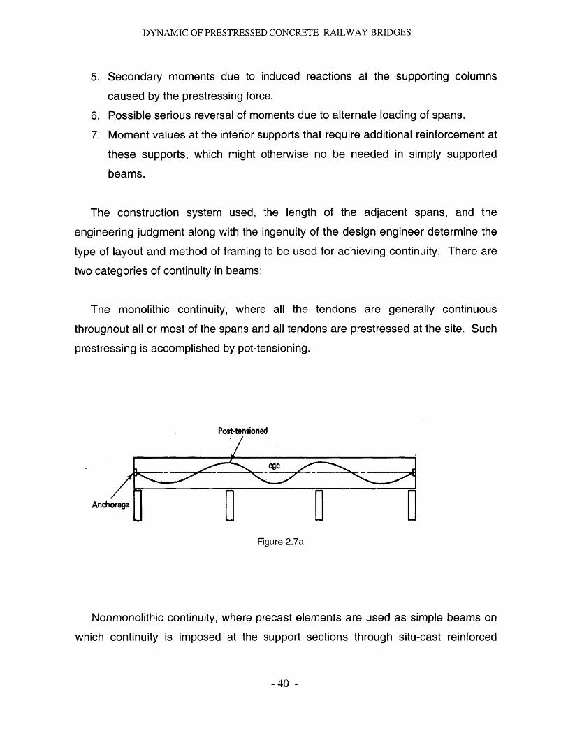
The monolithic continuity, where all the tendons are generally continuous
throughout all or most of the spans and all tendons are prestressed at the site. Such
prestressing is accomplished by pot-tensioning.
Post-tensioned
Anchorage
Figure 2.7a
Nonmonolithic continuity, where precast elements are used as simple beams on
which continuity is imposed at the support sections through situ-cast reinforced
-40 -
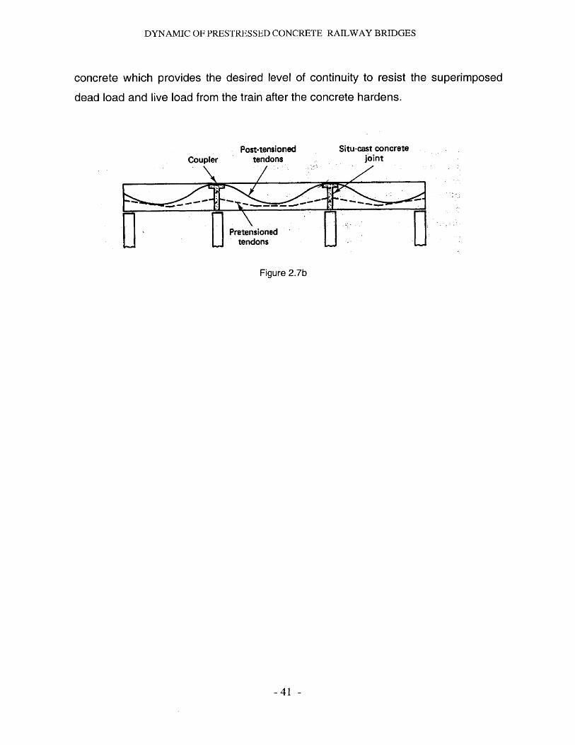
DYNAMIC OF PRESTRESSED CONCRETE RAILWAY BRIDGES
concrete which provides the desired level of continuity to resist the superimposed
dead load and live load from the train after the concrete hardens.
Post-tensionedtendons
Situ-cast concretejoint
Figure 2.7b
-41 -
Coupler
Pretensionedtendons
DYNAMIC OF PRESTRESSED CONCRETE RAILWAY BRIDGES
3. Dynamic effects on structures derived from High-Velocity.
3.1. Rail bridge structural dynamics evolution.
The discipline of railway bridge dynamics has a rich history and great attention
has been paid to the study of bridge dynamics all over the world. During the
construction of the first railways in England in the first half of the 19th century, the
engineers were split into two groups. One believed that the passage of a railway
locomotive along the bridge would generate enough time to become deformed during
the engine passage. For this reason, this very early period gave rise to the first
experiments an to the first theoretical studies which suggested that the actual effect of a
moving railway locomotive on the bridge would lie somewhere between those two
extreme opinions mentioned above Since that time the dynamics of railway bridges has
received consistent attention in most technically developed countries all over the world.
Between the two World Wars the dynamics of railway bridges was given greatest
attention in the former USSR and in Great Britain. It was in this period of time when the
two fundamental problems of motion of a constant and of an harmonically variable force
along a beam were solved as well as the effects of steam railway locomotives on the
statically indeterminate continuous, frame and arch railway bridges. For decades, many
schools all over the world focus on the study of this discipline both theoretically and
experimentally.
3.2. Dynamic Analysis
The dynamics of railway bridges is concerned with the study of deflections and
stresses in railway bridges. The loads that participate in this scientific discipline are
represented by the moving wheel and axle forces, by means of which railway vehicles
transmit their load and inertia actions to railway bridges.
- 42 -
DYNAMIC OF PRESTRESSED CONCRETE RAILWAY BRIDGES
There are numerous parameters which may influence the magnitude of dynamic
strains and stresses. The most important parameters influencing the dynamic stresses
for this structures are the frequency characteristics of bridge structures (length, mass,
and rigidity of individual members), the frequency characteristic of vehicles, the
damping in bridges and in vehicles, the velocity of vehicle movement, the track
irregularities, as well as others.
The vehicles affect the bridges not only by vertical forces, but also by movements
which generate longitudinal and transverse horizontal forces. This effects results in an
increase or decrease of bridge deformations comparing to the ones from the static
loading effects. In engineering design practice the procedure is to consider a static
effect multiplier factor which states how many times it has to be increased in order to
cover the additional dynamic loads. This factor is very simple and does not take into
account most of the parameters which influence the dynamic behavior of the structure.
However, the factor is accurate enough as for ensuring the safety and reliability of this
types of bridges.
Other factor to be taken into account is the fatigue of the structure. Because of the
large number of vibration effects that a railway bridge may be subjected to during its life-
cycle this may be a serious problem. A new approach may be followed which assumes
that the magnitude and number of stress cycles generated in the bridge by the passage
of all trains during its service life. Although this approach is closer to reality it will not be
considered for the present study.
3.2.1. Deterministic vibration
The response of a railway bridge to the passage of a vehicle manifests itself as
vibration. By deterministic vibration we understand the motion which can be predicted
at all times. The basic model from the field of vibrations is a system with one degree of
-43 -

DYNAMIC OF PRESTRESSED CONCRETE RAILWAY BRIDGES
freedom whose motion is described, according
D'Alembert's principle, by the differential equation
d 2v(t)
dt 2+b dv(t) + kv(t) = F(t)
dt
to Newton's second law and
(46)
where
v(t) = displacement of body of mass m at time t
m = lumped mass of the system
b = 2mwb damping force at unit velocity
k= stiffness or rigidity of the spring, assumed constant
F(t) = external force dependent on time t
The fundamental concepts in the field of vibrations are the natural circular
frequency of the system as (Equation 46).
c00 = (k (47)
the circular frequency of damped vibrations with subcritical damping
(48)() = t)2 _ )2d 00 6 b
the natural frequencies of undamped or damped vibrations derived from it
2)
f - 2fd 2)7
(49)
(50)
-44 -

DYNAMIC OF PRESTRESSED CONCRETE RAILWAY BRIDGES
respectively, and the period of natural vibrations
1T, =
1fd
(51)
(52)
respectively, this being the shortest time after which the vibration repeats.
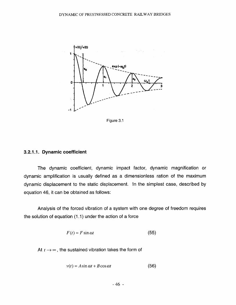
The damping of the system, as shown in equation 46, is characterized most
frequently by the logarithmic decrement of damping, , which is defined as the natural
logarithm of the ratio of any two successive amplitudes of like sign after time Td. In the
case of damping proportional to vibration velocity, this ratio is constant. In practice, it is
often determined on the basis of n successive vibrations.
In sn sn
(53)
where s, is the amplitude after the nth cycle as shown in figure 3.1.
The relation of the logarithmic decrement of damping to the constant b or wb in
equation (46) is
(= = b
fd 2mfd(54)
-45 -
DYNAMIC OF PRESTRESSED CONCRETE RAILWAY BRIDGES
01
v(t)/v(0)
i xp K12
Figure 3.1
3.2.1.1. Dynamic coefficient
The dynamic coefficient, dynamic impact factor, dynamic magnification or
dynamic amplification is usually defined as a dimensionless ration of the maximum
dynamic displacement to the static displacement. In the simplest case, described by
equation 46, it can be obtained as follows:
Analysis of the forced vibration of a system with one degree of freedom requires
the solution of equation (1.1) under the action of a force
F(t) = F sin wt (55)
At t - oo , the sustained vibration takes the form of
v(t) = Asin wt + Bcoswt (56)
- 46 -
/T!,\ &Jd
t

DYNAMIC OF PRESTRESSED CONCRETE RAILWAY BRIDGES
After the substitution of equations (55) and (56) in equation (46) and a
comparison of coefficients of the individual terms we obtain the following expressions
for the constants A and B:
F(0)2-0)2 )A= ( - ow (57)m[()2 -w 2 ) 2 +4t 2a ] '
B =-M(t0 - 2F&>tob (58)m[ 't )2)2 +40> 2 )
The maximum amplitude of forced stationary vibrations is the vector sum of A
and B, so
S = (A 2 +B 2)1 2 = F kw) 2 2 )2 +4w02112/ (59)
The static displacement of a mass on the spring of stiffness k subjected to the
force F, according to the definition of the spring stiffness (equation (47), is
F FVS F (60)
k m_ 2
The dynamic coefficient for the simplest case of forced vibration of a system with
one degree of freedom is the defined as the ratio of the maximum dynamic
displacement (59) and the static displacement (60)
_- 2 _(-_)2_+ (61)St 0
-47 -
DYNAMIC OF PRESTRESSED CONCRETE RAILWAY BRIDGES
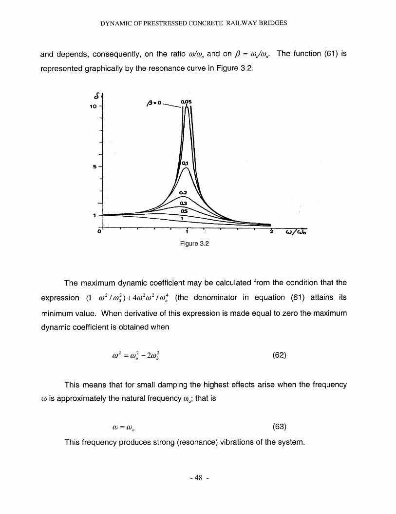
and depends, consequently, on the ratio co, and on 8 = (o/c,.
represented graphically by the resonance curve in Figure 3.2.
10 -I
5
I
a
The function (61) is
0.1o
0.2
0.3
~J/~jo*1
Figure 3.2
The maximum dynamic coefficient may be calculated from the condition that the
expression (1-)2 /w 2 )+4(0 269 2 / (the denominator in equation (61) attains its
minimum value. When derivative of this expression is made equal to zero the maximum
dynamic coefficient is obtained when
(0 2 =2 -22 (62)
This means that for small damping the highest effects arise when the frequency
w is approximately the natural frequency o.; that is
0 = 0 0 (63)
This frequency produces strong (resonance) vibrations of the system.
-48 -
CJ/66
DYNAMIC OF PRESTRESSED CONCRETE RAILWAY BRIDGES
If we substitute the excitation frequency (62) into equation (61), we obtain the
maximum values of the dynamic coefficient (see also equations (54) and (55).
02 (0 1 z imax = " = = (64)
2 Ob (d 2Cwb 2,8 j
Equation (64) shows that maximum dynamic effect in resonance conditions
depends chiefly on the damping characteristics of the system (it is indirectly proportional
to the logarithmic decrement of damping).
3.2.2. Theoretical Bridge models
Railway bridges are generally long structures which is reflected also in the
theoretical models used in their analysis. In principle, theoretical models of railway
bridges are of two types: those with continuously distributed mass and those with mass
concentrated in material points (lumped masses), or their combinations. The choice of
an adequate model depends on the particular case and on the purpose of the analysis.
3.2.3. Beams
The railway bridge model most frequently used is a beam which models well and
simply the linear character of the structure which has small transverse dimension when
compared with its length.
3.2.4. Mass Beams
If the mass of the bridge structure is comparable with or considerably higher than
the mass of the vehicles, it cannot be neglected. This is the case for medium and large
- 49 -
DYNAMIC OF PRESTRESSED CONCRETE RAILWAY BRIDGES
span bridges. In this way the mass beam is necessary which is used most frequently of
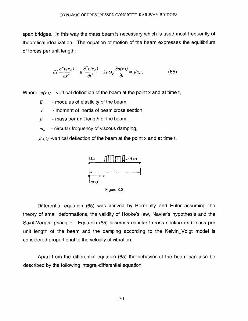
theoretical idealization. The equation of motion of the beam expresses the equilibrium
of forces per unit length:
a4 v(x, t) 2v(x, t) a(X t)EI 4' + p 2' + 2p(t> '= f(xat)
ax4 at2 at(65)
Where v(xt) - vertical deflection of the beam at the point x and at time t,
E - modulus of elasticity of the beam,
I - moment of inertia of beam cross section,
p- mass per unit length of the beam,
01a - circular frequency of viscous damping,
f(x,t) -vertical deflection of the beam at the point x and at time t,
E ,lu f(x
X
V X't)
Figure 3.3
Differential equation (65) was derived by Bernoully and Euler assuming the
theory of small deformations, the validity of Hooke's law, Navier's hypothesis and the
Saint-Venant principle. Equation (65) assumes constant cross section and mass per
unit length of the beam and the damping according to the KelvinVoigt model is
considered proportional to the velocity of vibration.
Apart from the differential equation (65) the behavior of the beam can also be
described by the following integral-differential equation
- 50 -
DYNAMIC OF PRESTRESSED CONCRETE RAILWAY BRIDGES
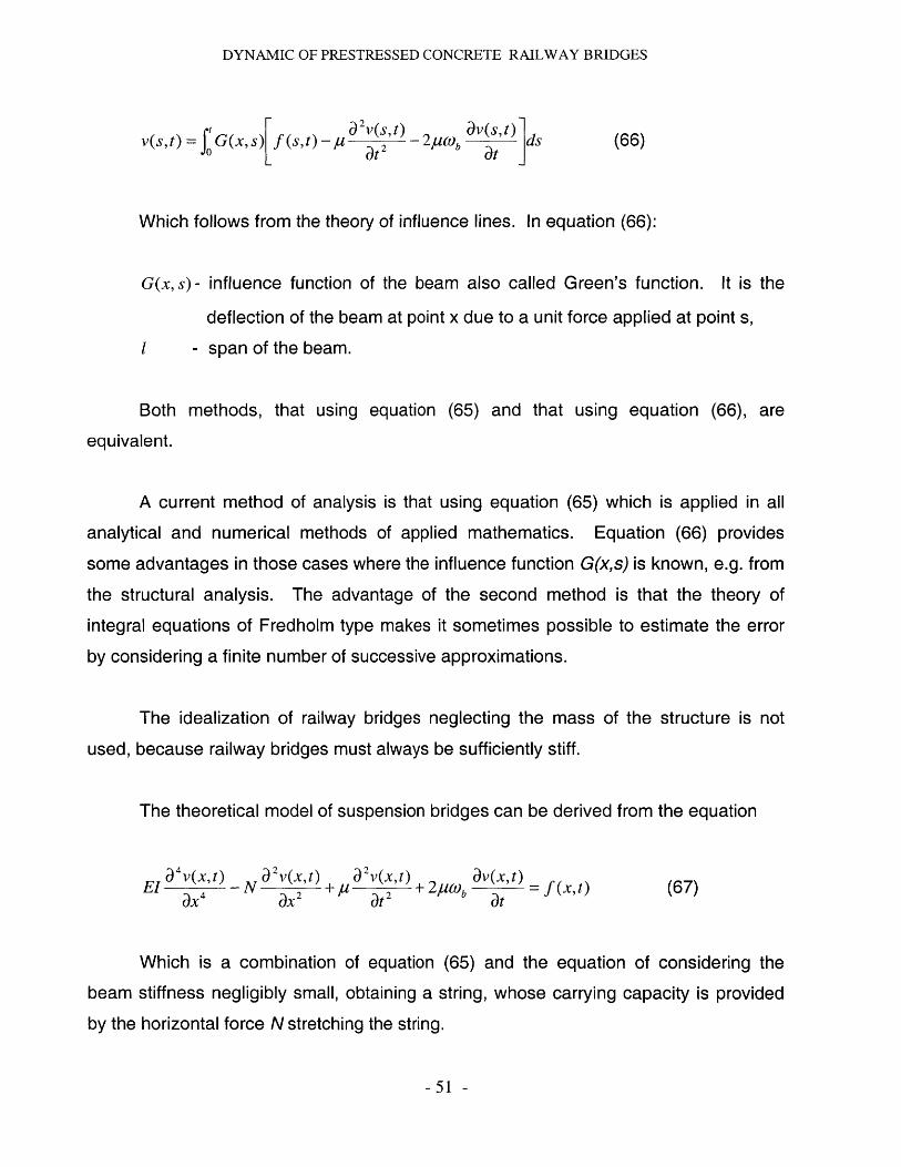
v(s, t)=f IG(x,s) f(s,t)-pl a2t 29b 2a>, ds (66)
Which follows from the theory of influence lines. In equation (66):
G(x, s) - influence function of the beam also called Green's function. It is the
deflection of the beam at point x due to a unit force applied at point s,
1 - span of the beam.
Both methods, that using equation (65) and that using equation (66), are
equivalent.
A current method of analysis is that using equation (65) which is applied in all
analytical and numerical methods of applied mathematics. Equation (66) provides
some advantages in those cases where the influence function G(xs) is known, e.g. from
the structural analysis. The advantage of the second method is that the theory of
integral equations of Fredholm type makes it sometimes possible to estimate the error
by considering a finite number of successive approximations.
The idealization of railway bridges neglecting the mass of the structure is not
used, because railway bridges must always be sufficiently stiff.
The theoretical model of suspension bridges can be derived from the equation
EI a 4 v(xt) _ N a 2 v(x,t) a 2v(x,t) + 2po av' (x t) (67)
ax 4 ax at 2 at
Which is a combination of equation (65) and the equation of considering the
beam stiffness negligibly small, obtaining a string, whose carrying capacity is provided
by the horizontal force N stretching the string.
-51 -
DYNAMIC OF PRESTRESSED CONCRETE RAILWAY BRIDGES
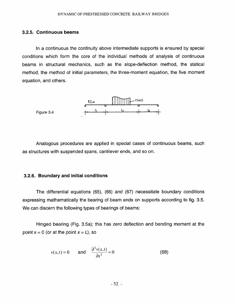
3.2.5. Continuous beams
In a continuous the continuity above intermediate supports is ensured by special
conditions which form the core of the individual methods of analysis of continuous
beams in structural mechanics, such as the slope-deflection method, the statical
method, the method of initial parameters, the three-moment equation, the five moment
equation, and others.
ELMV
JJITh2Lf (xt)U2
V
Figure 3.4
Analogous procedures are applied in special cases of continuous beams, such
as structures with suspended spans, cantilever ends, and so on.
3.2.6. Boundary and initial conditions
The differential equations (65), (66) and (67) necessitate boundary conditions
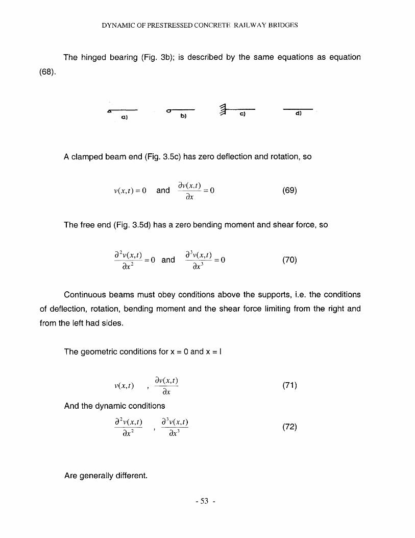
expressing mathematically the bearing of beam ends on supports according to fig. 3.5.
We can discern the following types of bearings of beams:
Hinged bearing (Fig. 3.5a); this has zero deflection and bending moment at the
point x = 0 (or at the point x = L), so
v(x,t) = 0 and a2V(x, t) = 0ax2
- 52 -
(68)
-
DYNAMIC OF PRESTRESSED CONCRETE RAILWAY BRIDGES
The hinged bearing (Fig. 3b); is described by the same equations as equation
(68).
C) b) d)
A clamped beam end (Fig. 3.5c) has zero deflection and rotation, so
av(x,t )v(x,t) = 0 and = 0ax
(69)
The free end (Fig. 3.5d) has a zero bending moment and shear force, so
a2v(x,t) = aa dt) =
ax2 -0 and aX 3(70)
Continuous beams must obey conditions above the supports, i.e. the conditions
of deflection, rotation, bending moment and the shear force limiting from the right and
from the left had sides.
The geometric conditions for x = 0 and x = I
v(x, t)av(x, t)
ax(71)
And the dynamic conditions
a 2v(x,t)
ax 2
a3V(Xt)ax3
(72)
Are generally different.
- 53 -
-+ -C)
DYNAMIC OF PRESTRESSED CONCRETE RAILWAY BRIDGES
In the integral-differential equation (66) the boundary conditions are already
included in the influence functions G(x, s) which must satisfy them.
The initial conditions express the initial deformation and velocity of the structure
at the time t = 0 from which we begin the analysis. Naturally, they can also be functions
of spatial coordinates, such as for t = 0.
v(x, t)= g, (x) and aV(X t)g(x) (73)at
3.2.7. Prestressed concrete bridges
In prestressed concrete bridges, there are two principal cases: the prestressing
tendons are either perfectly grouted or are entirely free.
In prestressed concrete railway bridges the reinforcement is bounded with
concrete along the whole tendon length both in pre-tensioned and in post-tensioned
beams. Thus the state approaches the first case. In this case the prestress in the
tendons has no influence on the potential energy of the beam and, therefore, it does not
cause any changes in its natural frequencies. The overall forces applied to the element
of length do not vary, because the prestressing force is in equilibrium with the forces
compressing concrete. Therefore, in the case of grouted tendons, we proceed with the
dynamic analysis of the beam according to equation (65) as if the beam were not
subjected to an axial force. We include the concrete cross section in full and the ideal
cross section of reinforcement into the cross section area of the beam and prestress.
This procedure is applied, whether the beam is pre-tensioned or post-tensioned.
- 54 -
DYNAMIC OF PRESTRESSED CONCRETE RAILWAY BRIDGES
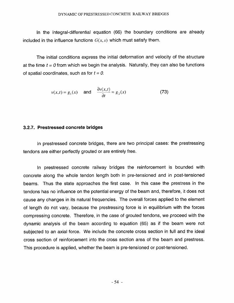
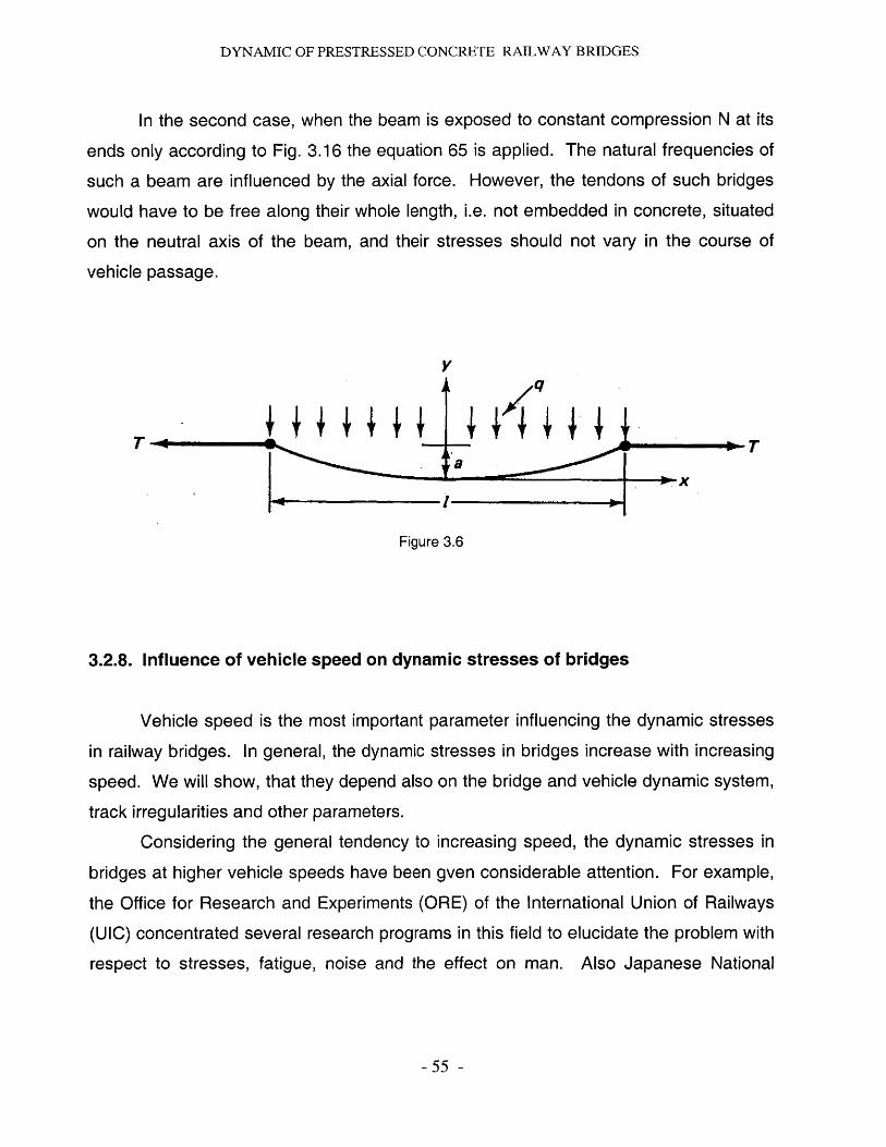
In the second case, when the beam is exposed to constant compression N at its
ends only according to Fig. 3.16 the equation 65 is applied. The natural frequencies of
such a beam are influenced by the axial force. However, the tendons of such bridges
would have to be free along their whole length, i.e. not embedded in concrete, situated
on the neutral axis of the beam, and their stresses should not vary in the course of
vehicle passage.
y
yq
T Ta
Figure 3.6
3.2.8. Influence of vehicle speed on dynamic stresses of bridges
Vehicle speed is the most important parameter influencing the dynamic stresses
in railway bridges. In general, the dynamic stresses in bridges increase with increasing
speed. We will show, that they depend also on the bridge and vehicle dynamic system,
track irregularities and other parameters.
Considering the general tendency to increasing speed, the dynamic stresses in
bridges at higher vehicle speeds have been gven considerable attention. For example,
the Office for Research and Experiments (ORE) of the International Union of Railways
(UIC) concentrated several research programs in this field to elucidate the problem with
respect to stresses, fatigue, noise and the effect on man. Also Japanese National
-55 -
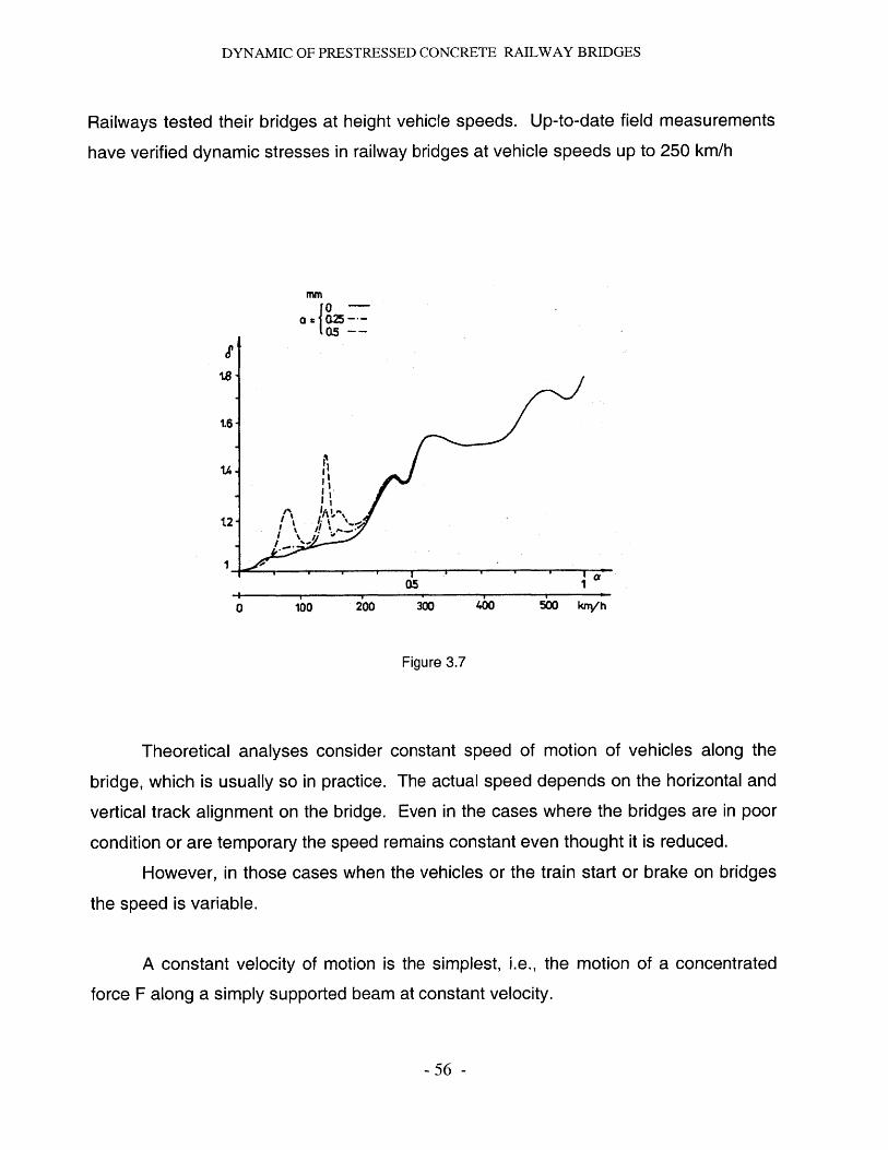
DYNAMIC OF PRESTRESSED CONCRETE RAILWAY BRIDGES
Railways tested their bridges at height vehicle speeds. Up-to-date field measurements
have verified dynamic stresses in railway bridges at vehicle speeds up to 250 km/h
rnn
S0-05
1.6
U.
I'I
0 1bo 20o 300 40 50 krn/h
Figure 3.7
Theoretical analyses consider constant speed of motion of vehicles along the
bridge, which is usually so in practice. The actual speed depends on the horizontal and
vertical track alignment on the bridge. Even in the cases where the bridges are in poor
condition or are temporary the speed remains constant even thought it is reduced.
However, in those cases when the vehicles or the train start or brake on bridges
the speed is variable.
A constant velocity of motion is the simplest, i.e., the motion of a concentrated
force F along a simply supported beam at constant velocity.
- 56 -
DYNAMIC OF PRESTRESSED CONCRETE RAILWAY BRIDGES
3.2.8.1. Motion based design.
3.2.8.1.1. Dynamic Considerations.
It is the main purpose of this paper to perform a dynamic analysis of a railway
track under moving vibratory masses will as well be studied in this thesis. In such
problems the critical velocity is an important parameter. This is influenced by the
dynamical characteristics of the moving load. The track is modeled as an infinitely long
Euler-Bernoulli beam on Winkler foundation. A novel approach to obtain the steady-
state response of the track subjected to N equispaced in-phase oscillatory moving
masses. Effects of mass spacing and number of masses on the resonant frequency and
critical velocity will be studied. Track response due to a moving oscillatory line mass
will also presented.
The loads are represented by the moving wheel and axle forces, by means of
which the railway vehicles transmit their load and inertia actions to the bridges. Thus
the dynamics of railway bridges involves the response of bridges to the movement of
vehicles and to the influence of a number of parameters which increase dynamic strains
or stresses. The most important parameters influencing the dynamic stresses in railway
bridges are: the frequency characteristics of bridge structures (i.e. the length, mass, and
rigidity of individual members), the frequency characteristic of vehicles (i.e. the sprung
and unsprung masses, the stiffness of springs), the damping in bridges and in vehicles,
the velocity of the vehicle movement, the track irregularities, and so on.
3.2.8.1.2. Critical speed.
It will be discussed in this paper, as mentioned before, the critical speed, the
'bow-wave' effect and how it is influenced by soil stiffness. In order to reach the centers
of major conurbation, modern high-speed rail lines are increasingly utilizing marginal
land avoiding previously built housing areas. This land often has low soil stiffness. The
critical speed of waves across such soils can approach the speed of modern high-speed
- 57 -

DYNAMIC OF PRESTRESSED CONCRETE RAILWAY BRIDGES
trains. The large deflections caused can increase environmental noise and the track
maintenance required and decrease ride quality. This paper discusses how.
The modeling of possible remedies to the problem will be discussed. A
convolution technique is used to model axles travelling at different speeds and the
effects of multiple axles. The resulting displacements are highly dependent on the
amount of damping introduced into the system modeled. In-situ testing, laboratory
testing and finite element modeling are compared and are shown to provide consistent
results. The conclusion is that a powerful analytical tool for the prediction of the 'bow-
wave' effect has been devised.
3.2.9. Influence of fatigue on dynamic stresses of bridges
The vehicles affect the bridges not only by vertical forces, but also by movements
which generate longitudinal and transverse horizontal forces. This results in an
increase or decrease of bridge deformations when compared to that due to static forces.
In design practice, these effects are described by the dynamic coefficient (or dynamic
impact factor) which, however, only states how many times the static effects must be
multiplied in order to cover the additional dynamic loads.
The fatigue assessment of bridges has resulted in the derivation of a new
approach. This assumes the magnitude and number of stress cycles generated in the
bridge by the passage of all trains during its service life. This approach, which is closer
to reality, has yielded valuable data for the fatigue assessment of bridges, for the
estimation of their fatigue life and for the determination of inspection intervals.
- 58 -
DYNAMIC OF PRESTRESSED CONCRETE RAILWAY BRIDGES
3.2.10. Influence of thermal contribution on dynamic stresses of bridges
Therefore, it will not be necessary to go over the problem of thermal interaction.
Although the temperature changes also depend on time the thermal effects do not
generate any vibration in bridges.
3.2.11. Influence of soil contribution on dynamic stresses of bridges
We have to take into account that the modern high-speed rail lines are being built
increasingly on marginal land, in order to reach city centers while avoiding housing
areas. Often this land is composed of soft alluvial soils, which exhibit a low resilient
modulus. The measurement, prediction, modeling, and implications of resilient modulus
values for such subgrades are being discussed. Measurement must consider the use of
repeated, load triaxial testing, resonant column, and in situ methods, illustrating these
with sample data. Prediction draws must be done on both analytical and finite-element
techniques to illustrate the critical speed, the bow-wave effect, in order to show how it is
influenced by resilient modulus. Modeling reveals the available relationships, and their
limitations, for deriving subgrade stiffness in this dynamic situation. Afterwards, this
data may be used to define the relevant effects of resilient modulus values on design
problems.
- 59 -
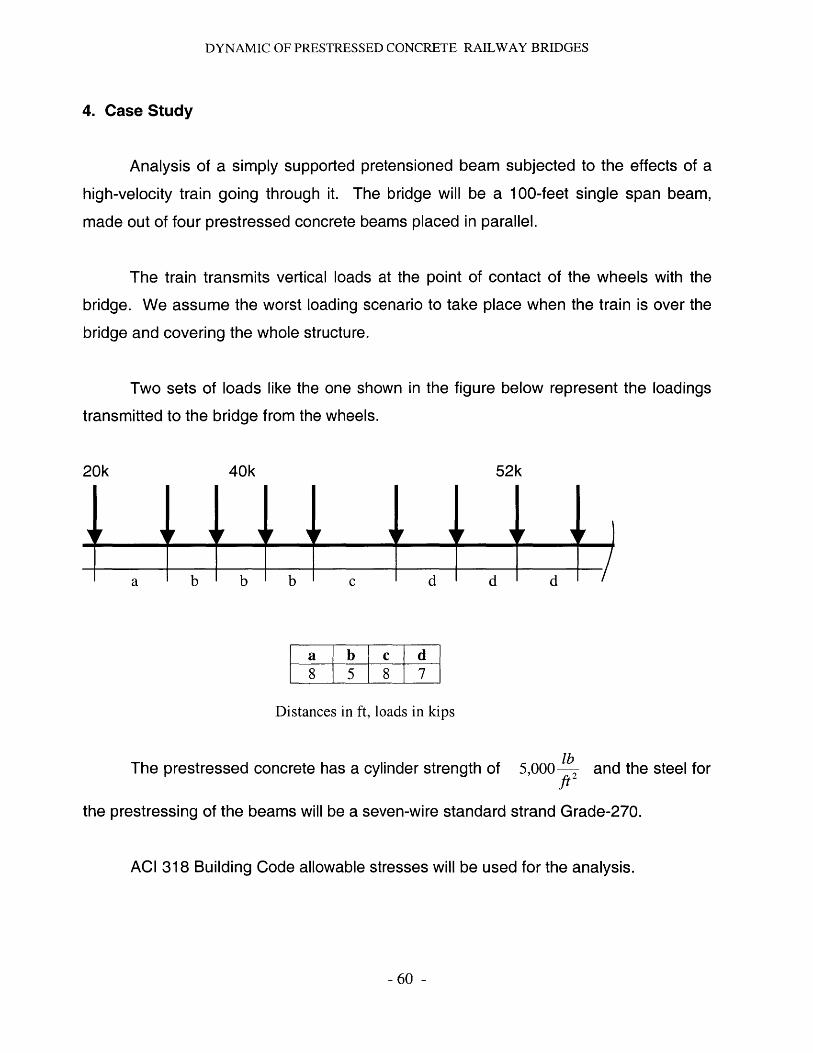
DYNAMIC OF PRESTRESSED CONCRETE RAILWAY BRIDGES
4. Case Study
Analysis of a simply supported pretensioned beam subjected to the effects of a
high-velocity train going through it. The bridge will be a 100-feet single span beam,
made out of four prestressed concrete beams placed in parallel.
The train transmits vertical loads at the point of contact of the wheels with the
bridge. We assume the worst loading scenario to take place when the train is over the
bridge and covering the whole structure.
Two sets of loads like the one shown in the figure below represent the loadings
transmitted to the bridge from the wheels.
20k 40k
I1
52k
__111(__111Z7a b b b c d d d I
a b c d8 5 8 7
Distances in ft, loads in kips
The prestressed concrete has a cylinder strength of 5,000 lbft2
and the steel for
the prestressing of the beams will be a seven-wire standard strand Grade-270.
ACI 318 Building Code allowable stresses will be used for the analysis.
- 60 -
I
DYNAMIC OF PRESTRESSED CONCRETE RAILWAY BRIDGES
4.1. The objectives of the analysis are:
1. Service Load Design of the pretensioned beam
2. Service Deflection Design
The study of the deflections, the simply supported beam is subjected to, is the main
purpose of this study. Two different analysis will be performed:
" Static loading induced deflections, at the beam midpoint, from the
element self-weight and the railway instrumentation related dead load.
" Dynamic deflections induced by the train moving over the bridge will also
be determined. The loading from the high-speed vehicle is transmitted to
the structure in different places, corresponding to the wheel locations
when the whole train is over the system. Those vertical displacements, at
the beam midpoint, will be statically determined and increased by a
dynamic impact ratio that takes into consideration the effects of the train
moving loads.
Since the study of the dynamic effect of the train moving over the bridge is
the main purpose of this thesis, a more detailed analysis of it will be
performed taking into consideration the sensitivity of behavior influencing
variables such as the velocity of the train, the span of the bridge and the
frequency of the loading induced by the vehicle.
4.1.1. Solution
4.1.1.1. Service Load Design
-61 -

DYNAMIC OF PRESTRESSED CONCRETE RAILWAY BRIDGES
The span of each of the four beams of the bridge will be as mentioned above
L =75ft =900in
The loads that the structure will be carrying are
The assumed load corresponding to the weight of the railway infrastructure
WL =100 lb = 25.0 lbft in
The living load transmitted to the bridge through the train wheels is described in the
figure 1.1. Each beam will be carrying half of every concentrated load.
The properties of the concrete to be used for the beam are the following:
The concrete cylinder strength f'c
The concrete strength at transfer f' I
The stress relieved tendons
lb=5,000 .l2
in
lb lb=0.75 -f' =0.75-5,000 i = 3,750 . 2
in in
lbf= 270,000 .2in
Time dependent losses of the initial prestress - is assumed to be approximately
18%
Then the ratio of initial prestress remaining after time dependent losses will be
100-18 = 0.82100
- 62 -
DYNAMIC OF PRESTRESSED CONCRETE RAILWAY BRIDGES
The maximum allowable compressive stress in concrete immediately
transfer and prior to losses is
lb lbfi = 0.60 -f 'e,=0.60-3750 .2 = 2,250 .b
in in
The maximum allowable compressive stress in concrete after losses at service-
load level is
f, = 0.45 -f 'c = 0.45 -5000 lbin
-2,250 lbin
The maximum allowable tensile stress in concrete immediately after transfer and
prior to losses is
f [3lb lb3 = 3 - 2,250 2 =142.3
in in
This value may be increased to 6 f'C
members, as it is our case
f, 1=6 f'7_=284.61lin
The bending moments induced to the midpoint of
maximum values, due to the different loading effects are
Bending moment MIns ,
at the supports for simply supported
the beam, where they get
due to the dead load from the railway related
infrastructures. This infrastructures are the rails, bolt connections, etc.
M - w'", -L2 - 25. 9002 -=843,800lb -in
8 8
Bending moment Mea due to the distributed self-weight of the beam
63 -
after
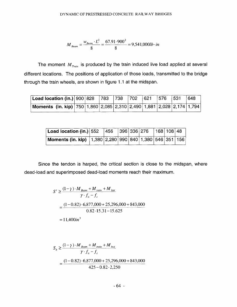
DYNAMIC OF PRESTRESSED CONCRETE RAILWAY BRIDGES
MBeam 8 2 = 9,541,0001b -in8
The moment MTrain is produced by the train induced live load applied at several
different locations. The positions of application of those loads, transmitted to the bridge
through the train wheels, are shown in figure 1.1 at the midspan.
Load location (in.) 900 828 783 738 702 621 576 531 648
Moments (in. kip) 750 1,860 2,085 2,310 2,490 1,881 2,028 2,174 1,794
Load location (in.) 552 456 396 336 276 168 108 48
Moments (in. kip) 1,380 2,280 990 840 1,380 546 351 156
Since the tendon is harped, the critical section is close to the midspan, where
dead-load and superimposed dead-load moments reach their maximum.
St>
(1- 0.82) -6,877,000 + 25,296,000 + 843,0000.82 -15.31-15.625
= 11,400in3
(1-)-M Beam + train Inst
Y -fi - fc
(1- 0.82) .6,877,000 + 25,296,000 + 843,000
425 -0.82 -2,250
- 64 -
(1 - ) -MBeam + M,,ain + Mns
Sb
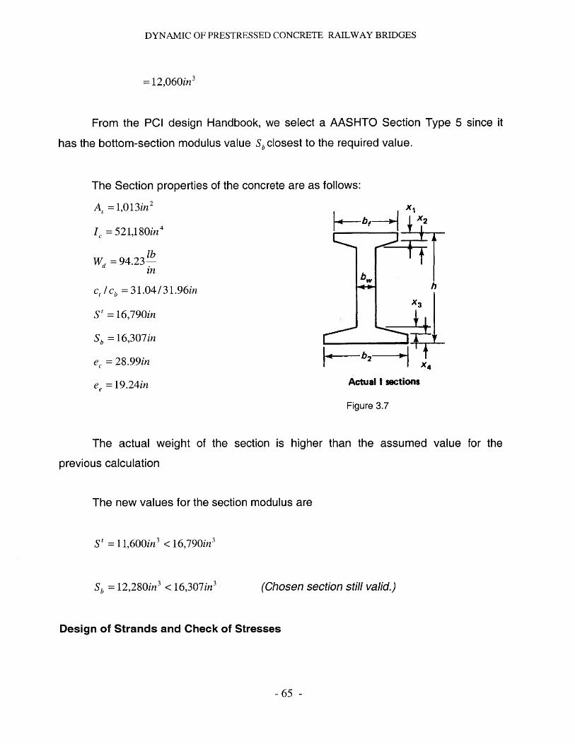
DYNAMIC OF PRESTRESSED CONCRETE RAILWAY BRIDGES
= 12,060in 3
From the PCI design Handbook, we select a AASHTO Section Type 5 since it
has the bottom-section modulus value Sbclosest to the required value.
The Section properties of the concrete are as follows:
A, =1,013in 2
IC =521,180in 4
lbWd =94.23-
in
C / Cb = 31.04/ 3 1. 9 6 in
St =16,790in
Sb = 16,307in
ec = 28.99in
ee =19.24in
bXK- X2
H-bw
b2tX4
Actual I sections
Figure 3.7
The actual weight of the section is higher than the assumed value for the
previous calculation
The new values for the section modulus are
S' =1 1,600in 3 <16,790in3
Sb = 12,280in3 < 16,307in3
Design of Strands and Check of Stresses
- 65 -
(Chosen section still valid.)

DYNAMIC OF PRESTRESSED CONCRETE RAILWAY BRIDGES
f,, = 0.70 -270,000 = 189,000psi
fpe = 0.82 - f,4 = 0.82 -189,000 = 154,980 psi
a) Analysis of Stresses at Transfer.
f' = P -ect MBeam <ti 184psi
184= - 11,013(
28.99 -31.04)21.642
pi = 908,100lb
The required number of tendons will be, considering Grade 270 seven-wire
standard strand, 0.6 in. nominal diameter,
n = p = 22.557sAs - Fi
with A, = 0.213in 2
We will try 20 - 0.6 in tendons for the standard section
A,, = 20-0.213 = 4.26in 2
P= A,, - = 805,100lb
Pe= Aps -fpe = 660,2001b
b) Analysis of the final stresses at service load at the beam midspan
- 66 -
9,541,00016,790
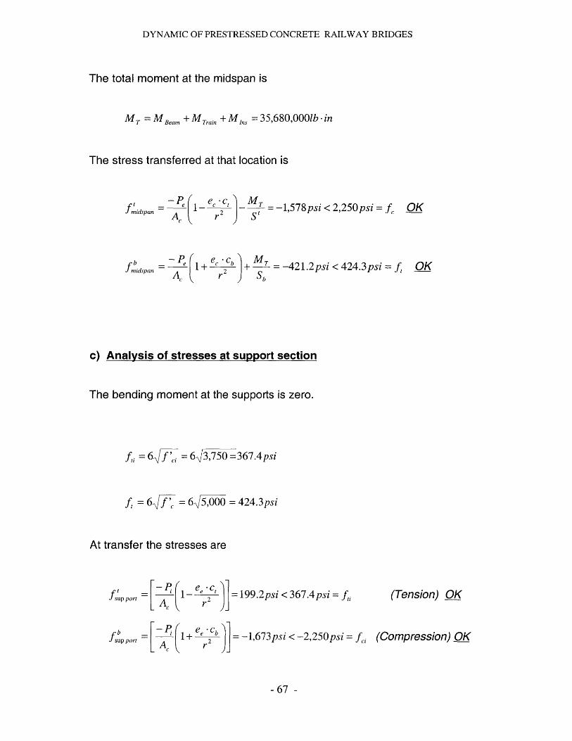
DYNAMIC OF PRESTRESSED CONCRETE RAILWAY BRIDGES
The total moment at the midspan is
MT =M Beam + MTrain + M Ins = 35,680,000lb -in
The stress transferred at that location is
fmidspan -~
fldspan A,
e. ct- 2r
MT = -1,578 psi < 2,250 psi =S t
c, Cb M = -421.2psi < 424.3psi = fr Sb
Analvsis of stresses at suDDort section
The bending moment at the supports is zero.
f, =6 f=f 6,3,750 =367.4psi
f,=6 f= 6,5,000 = 424.3psi
At transfer the stresses are
fUp port -Pc:(_ ee -] = 199.2psi < 367.4psi = f,
fsp port = A P + eecb = -1,673psi < -2,250 psi = fa
(Tension) OK
(Compression) OK
67 -
OK
OK
c)

DYNAMIC OF PRESTRESSED CONCRETE RAILWAY BRIDGES
We set the apply a partial prestressing in the beams limiting the tensile stress in
the concrete to a certain number. By doing this we will be improving performance,
reducing cost by using a lower amount of prestress. Fully prestressed beams may
exhibit an undesirable amount of upward camber because of the eccentric prestressing
force, a displacement that is only partially counteracted by the gravity loads producing
downward deflection. This tendency is aggravated by creep in the concrete, which
magnifies the upward displacement due to the prestress force, but has little influence on
the downward deflection due to live loads, which may be only intermittently applied.
Cracks may form occasionally, when full service load is applied, but these will close
completely when that load is removed.
4.1.1.2. Analysis of deflections at beam midspan
4.1.1.2.1. Static loading induced deflections
We proceed with the analysis of the deflections produced on short-term for a
cracked prestressed concrete beam, what means that the member we are designing will
have the tension stresses limited to a certain value and therefore cracks will appear.
The deflection and camber at transfer at midspan due to a single harp or
depression of the prestressing tendon is
-Pe. 1P P(e -er)8EI 24EI
with
-68 -
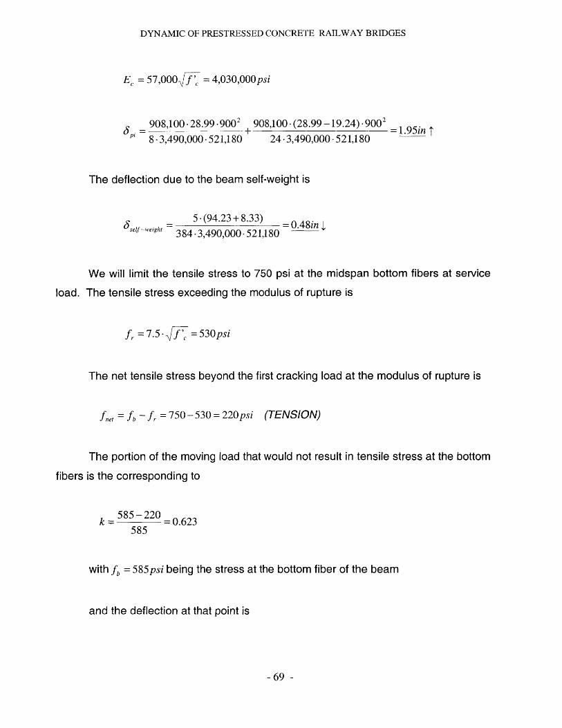
DYNAMIC OF PRESTRESSED CONCRETE RAILWAY BRIDGES
EC = 57,000 f' = 4,030,000 psi
908,100 -28.99 .9002
"8 -3,490,000-521,180
908,100. (28.99 -19.24) .9002
24 .3,490,000 -521,180=1.95in T
The deflection due to the beam self-weight is
5 -(94.23+ 8.33)self-weight 384-3,490,000-521,180
We will limit the tensile stress to 750 psi at the midspan bottom fibers at service
load. The tensile stress exceeding the modulus of rupture is
f, = 7.5- = 530psi
The net tensile stress beyond the first cracking load at the modulus of rupture is
fnet = fb- f, =750 - 530 = 220psi (TENSION)
The portion of the moving load that would not result in tensile stress at the bottom
fibers is the corresponding to
k = 585-220 = 0.623585
with fb = 585psi being the stress at the bottom fiber of the beam
and the deflection at that point is
- 69 -
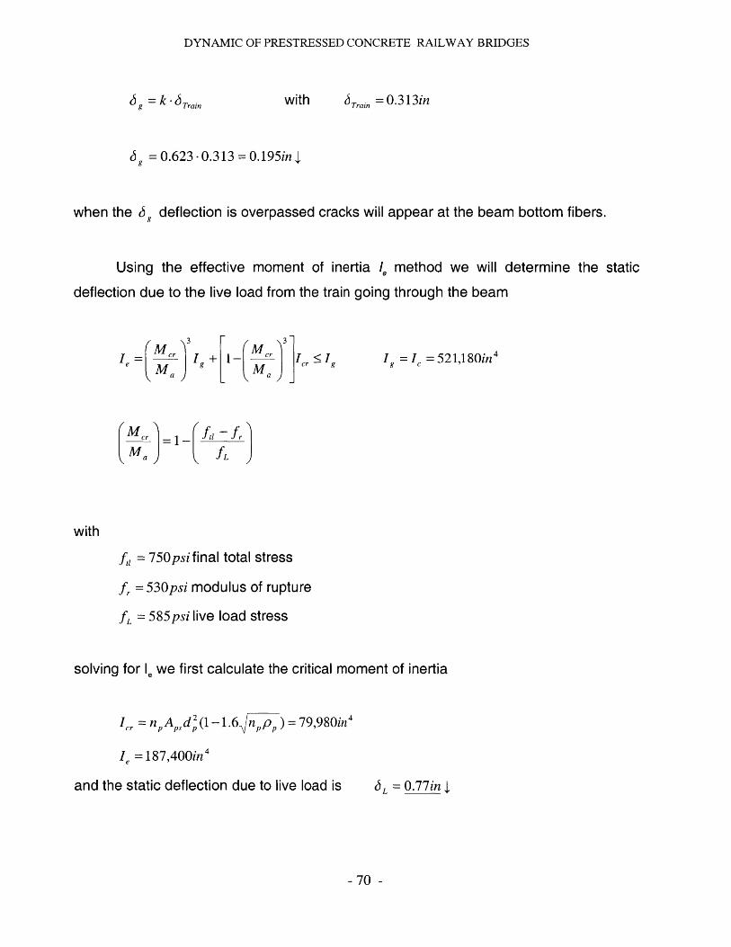
DYNAMIC OF PRESTRESSED CONCRETE RAILWAY BRIDGES
J9 =k-Train with J Train =0.313in
6 = 0.623 -0.313 = 0.195in
when the 6 9 deflection is overpassed cracks will appear at the beam bottom fibers.
Using the effective moment of inertia 1, method we will determine the static
deflection due to the live load from the train going through the beam
Mej
M aI + [1
ftifr
- Mer r : I
MI9 = I =521,180in 4
:3
fi = 750psifinal total stress
fr = 530psi modulus of rupture
fL = 585psi live load stress
solving for 1e we first calculate the critical moment of inertia
Icr =n, Ad 2(1-1 .6 p ) =79,980in4
Ie =187,400in 4
and the static deflection due to live load is JL = 0.77inI
- 70 -
with
Ie=
M a
DYNAMIC OF PRESTRESSED CONCRETE RAILWAY BRIDGES
4.1.1.2.2. Dynamic deflections
We will perform the analysis of the dynamic behavior of the prestressed concrete
beam. In order to do it we will be considering the midspan point since it is the most
critical one due to the superposition of dead load, beam self-weight and the effects of
the train over the bridge.
The vertical effects from the vehicle on the beam results in an increase or
decrease of bridge deformations comparing to the ones from the static loading effects.
A design practice procedure is to consider a static effect multiplier factor which states
how many times it has to be increased in order to cover the additional dynamic loads.
This factor is very simple and does not take into account most of the parameters which
influence the dynamic behavior of the structure. However, the factor is accurate enough
as for ensuring the safety and reliability of this types of bridges.
We will consider several loadings applied from the train to the beam when the
vehicle covers totally the structure. Neglecting damping and assuming the simplified
shape function of the beam deformation to be equal to the first mode of vibration, we will
determine an equation for the deflection at midspan as a function of time.
Then we will determine the dynamic impact ratio that reduces of magnifies the
static deflection of the structure at the selected midpoint. The velocity of the train has
an important influence on the dynamic response; therefore, the critical one at which it is
maximum, will be as well determined.
The conclusion of this dynamic study is to be able to determine if the high
velocity loading effect is a determinant factor in the design and in case it is, what is the
influence on the cost of the structure.
-71 -
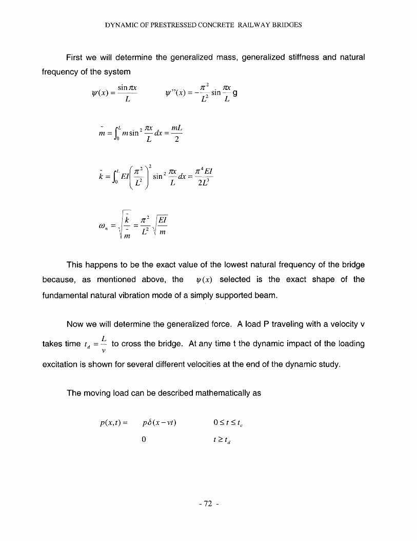
DYNAMIC OF PRESTRESSED CONCRETE RAILWAY BRIDGES
First we will determine the generalized mass, generalized stiffness and natural
frequency of the system
(x) = si L2
= ]sin
L 2 x mL
m=f m sin Ldx =2- L 2
~ _ LEI sinnd rtEL 2P
k T2 Ei
This happens to be the exact value of the lowest natural frequency of the bridge
because, as mentioned above, the ip(x) selected is the exact shape
fundamental natural vibration mode of a simply supported beam.
Now we will determine the generalized force. A load P traveling with a velocity v
Ltakes time td = - to cross the bridge. At any time t the dynamic impact of the loading
V
excitation is shown for several different velocities at the end of the dynamic study.
The moving load can be described mathematically as
p(x,t) = p5(x -vt)
0
0O t < t
t td
- 72 -
of the

DYNAMIC OF PRESTRESSED CONCRETE RAILWAY BRIDGES
where 6 (x - vt) is the Dirac delta function centered atx = v -t; it is a mathematical
description of the traveling concentrated load. The generalized force is
~ L Lp(t )=f' p(x,t jyf(x)dx =f p6(x -vt )sin(7x 1L)dx
p sin(ivt I L)
0
0 t < t
t td
This generalized force is a half-cycle sine pulse.
We will solve now the equation of motion
mz+kz = p(t)
The defined generalized equations describe the response of a single degree of
freedom system to a half-cycle sine pulse. This solution will be considered to the bridge
problem by changing the notation from u(t) to z(t), that refers to the vertical
displacements at the bridge and noting that
Ltd = -
V2non
(Zs,) 0 = 2pk mLO)2
The results will be
t Liv2p I . 1ryt )7Z(t)= C2 2 sin-- - sin cnt
mV~L n2-(nv/L2 L conL
-73 -
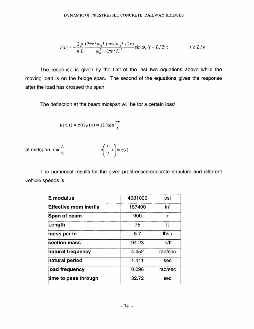
DYNAMIC OF PRESTRESSED CONCRETE RAILWAY BRIDGES
2p (2zv IwL)cos(woLI2v)Z~) mL 0) 2 - (av/ L)'
t > Liv
The response is given by the first of the last two equations above while the
moving load is on the bridge span. The second of the equations gives the response
after the load has crossed the span.
The deflection at the beam midspan will be for a certain load
u(x, t) = z(t)qf (x) = z(t) sin LL
Lat midspan x = -2
(L Zu ,t i=z(t)y2 )
The numerical results for the given prestressed-concrete structure and different
vehicle speeds is
- 74 -
E modulus 4031000 psi
Effective mom Inertia 187400 In 4
Span of beam 900 in
Length 75 ft
mass per in 5.7 lb/in
section mass 94.23 lb/ft
natural frequency 4.452 rad/sec
natural period 1.411 sec
load frequency 0.096 rad/sec
time to pass through 32.72 sec
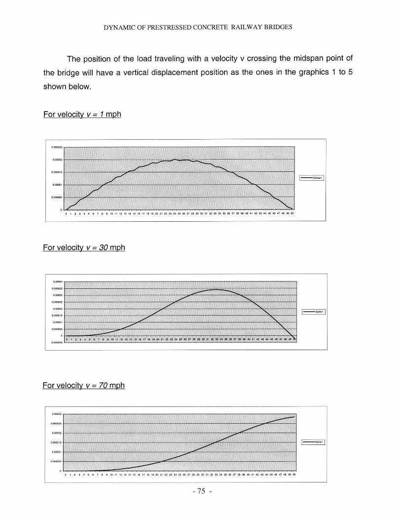
DYNAMIC OF PRESTRESSED CONCRETE RAILWAY BRIDGES
The position of the load traveling with a velocity v crossing the midspan point of
the bridge will have a vertical displacement position as the ones in the graphics 1 to 5
shown below.
For velocity v = 1 mph
0,000025-----
0000025
0 1 2 3 4 5 6 7 8 9 10 11 12 13 14 15 16 17 18 19 20 21 22 23 24 25 26 27 28 29 30 31 32 33 34 35 36 37 38 39 40 41 42 43 4445 46 47 48 49 0
For velocity v =30 mph
50 2 3 4 8 8 7 8 5 10 11 100304 15380 7 1i831 00 2 23 24 7 0 8 2 0 31 32 3493 87a3549 40 243 44446 47 48@4
For velocity v = 70 mph
0.0000035~~
0 I 2 3 4 5 6 7 8 9 10 11 121314 15 1817181920 2122 23240286272282930 3132 33 34 3536 37338340 41 42 43444546 47 48 480
75
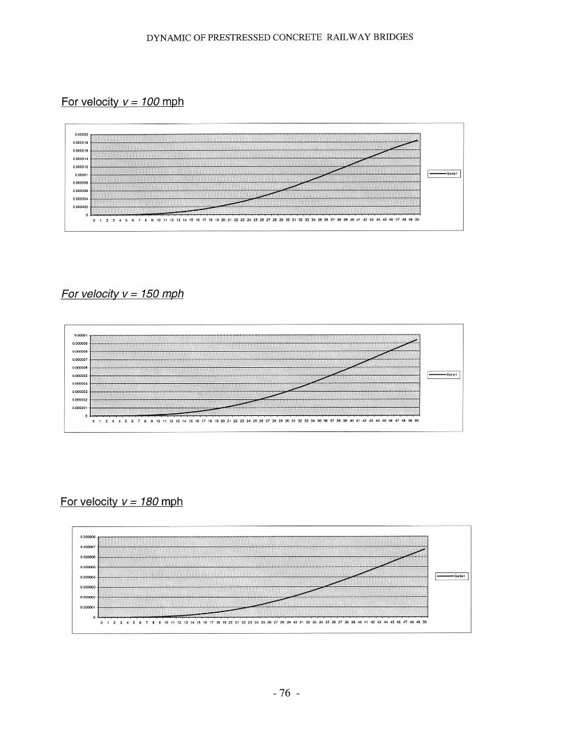
DYNAMIC OF PRESTRESSED CONCRETE RAILWAY BRIDGES
For velocity v = 100 mph
0m I
For velocity v=15mp0123401
For velocity v= 8mp
000000. .
0 1 2 3 4 5 6 7 8 9 10 11 12 13 14 15 16 17 18 19 20 21 22 23 24 25 26 27 28 29 30 31 32 33 34 35 36 37 3 39 40 41 42 43 44 45 46 47 48 49 50
- 76 -
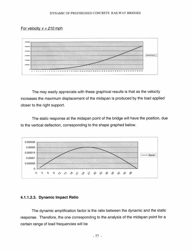
DYNAMIC OF PRESTRESSED CONCRETE RAILWAY BRIDGES
For velocity v = 210 mph
The may easily appreciate with these graphical results is that as the velocity
increases the maximum displacement of the midspan is produced by the load applied
closer to the right support.
The static response at the midspan point of the bridge will have the position, due
to the vertical deflection, corresponding to the shape graphed below.
0.000025
0.00002-
0.000015
0.00001 Serie1
0.000005
0
4.1.1.2.3. Dynamic Impact Ratio
The dynamic amplification factor is the ratio between the dynamic and the static
response. Therefore, the one corresponding to the analysis of the midspan point for a
certain range of load frequencies will be
- 77 -
0.000006 .. ....
0.D00005
O.DDDD04
0.00DG03
0.000002
0.000001
0
6 . . . . . . . . . . . . . . . . .10 11 12 13 14 15 16 17 18 19 20 21 22 23 24 25 26 27 28 29 30 31 32 33 34 35 36 37 3a 39 40 41 42 43 44 45 46 47 48 49 50
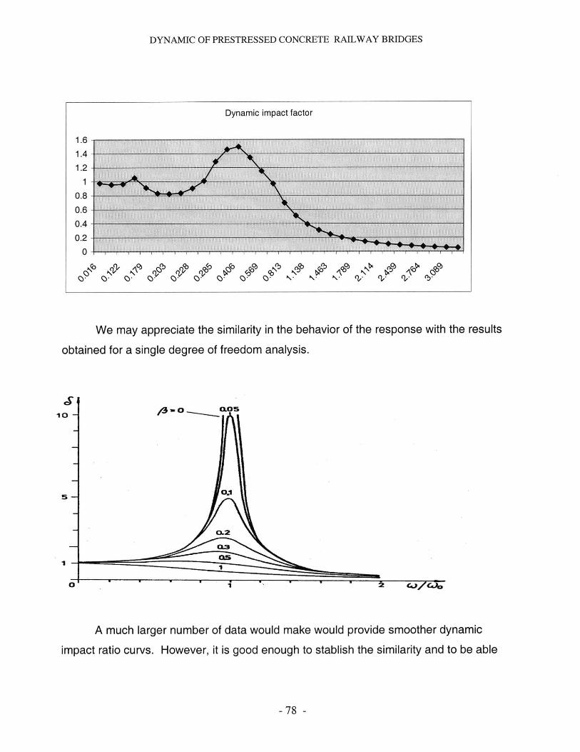
DYNAMIC OF PRESTRESSED CONCRETE RAILWAY BRIDGES
Dynamic impact factor
1.61.41.2
14
0.8
0.60.4
0.2
0
0b 0p 0b 03 0c 0 0 \ N ( (i..
We may appreciate the similarity in the behavior of the response with the results
obtained for a single degree of freedom analysis.
0
*1
A much larger number of data would make would provide smoother dynamic
impact ratio curvs. However, it is good enough to stablish the similarity and to be able
- 78 -
10
5
I
tj I e C-1,zG-6
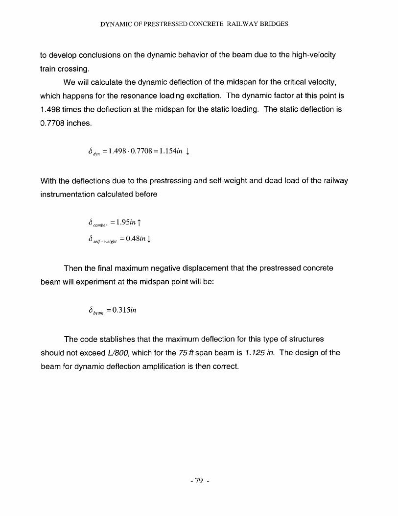
DYNAMIC OF PRESTRESSED CONCRETE RAILWAY BRIDGES
to develop conclusions on the dynamic behavior of the beam due to the high-velocity
train crossing.
We will calculate the dynamic deflection of the midspan for the critical velocity,
which happens for the resonance loading excitation. The dynamic factor at this point is
1.498 times the deflection at the midspan for the static loading. The static deflection is
0.7708 inches.
J dyn =1.498 -0.7708 =1.154in 4
With the deflections due to the prestressing and self-weight and dead load of the railway
instrumentation calculated before
,,camber =1.95in 1
J self-weight =0.48in 4
Then the final maximum negative displacement that the prestressed concrete
beam will experiment at the midspan point will be:
J beam =0.315in
The code stablishes that the maximum deflection for this type of structures
should not exceed L/800, which for the 75 ft span beam is 1.125 in. The design of the
beam for dynamic deflection amplification is then correct.
- 79 -
DYNAMIC OF PRESTRESSED CONCRETE RAILWAY BRIDGES
References
1. Deflection ordinates for single-span and continuous beams. Georg Anger and
Karl Tranmm. New Yorkl 965
2. Bridge engineering : design, rehabilitation, and maintenance of Bridges.
Tonias, Demetrios E. New York 1995
3. Dynamics of structures. Anil K. Chopra, University of Berkeley. New Jersey 1995
4. High Performance Maglev Guideway Design. Scott Phelan, PhD Thesis.
Massachusetts Institute of Technology. January 1993.
5. Transportation Vehicle/Beam Elevated Guideway Dynamic Iterations.
Richardson and Wormley 74. "A state of the art review". Journal of Dynamic Systems,
Measurement and Control. ASME, P1-11 (1974)
6. Obras Publicas: Revista del Colegio de Ingenieros de Caminos, Canales y
Puertos. "Los puentes del futuro. Angel Aparicio Bengoechea. ". N 20 / Verano
1991, P 6 - 21
7. Obras Publicas: Revista del Colegio de Ingenieros de Caminos, Canales y
Puertos. "Puentes de hormig6n pretensado para lineas ferroviarias de Alta
Velocidad". Reiner Saul. N 20 / Verano 1991, P 40 - 51
8. Dynamic Response of elevated High-speed railway. Yung-Hsiang Chen and
Chen-Yu Li. Journal of Bridge Engineering. May 2000. Pg 124-131.
9. Design of Prestressed Concrete Structures. T Y Lin / Ned H. Burns. Edit. Wiley,
John & Sons Incorporated. November 1990
10. Design of Prestressed Concrete. Arthur H. Nilson. Edit. Wiley, John & Sons
Incorporated. March 1987.
11. Launched Bridges. Marcho Rosignoli. June 1998
12. The Cantilever Construction of Prestressed Concrete Bridges. Jacques
Mathivat. Edit. Wiley, John & Sons Incorporated. January 1984.
- 80 -

DYNAMIC OF PRESTRESSED CONCRETE RAILWAY BRIDGES
13. Dynamics of Railway Bridges. Ladislav Fryba. American Asociation of Civil
Engineers. January 1996.
14. Structural Analysis: A Unified Classical and Matrix Approach. A Ghali , A. M.
Neville. 3rd Edition, New York 1972.
15. Prestressed Concrete: A fundamental Approach. Edward G. Nawy. 2 nd
Edition, New Jersey 1995.
-81 -