Dynamics of Anisotropically Supported Rotorsdownloads.hindawi.com/journals/ijrm/1997/146971.pdf ·...
12
International Journal of Rotating Machineo’ 1997, Vol. 3, No. 2, pp. 133-142 Reprints available directly from the publisher Photocopying permitted by license only (C) 1997 OPA (Overseas Publishers Association) Amsterdam B.V. Published in The Netherlands under license by Gordon and Breach Science Publishers Printed in Singapore Dynamics of Anisotropically Supported Rotors AGNES MUSZYNSKA, Ph.D.*, CHARLES T. HATCH and DONALD E. BENTLY Bently Rotor Dynamics Research Corporation, P.O. Box 2529, Minden, Nevada 89423 (Received 15 May 1996; In final form 14 June 1996) The paper discusses dynamic effects occurring in machinery rotors supported in bearings and pedestals with laterally different characteristics. In the considered rotor model the anisotropy of radial stiffness and tangential ("cross") stiffness components are included. Within certain ranges of the rotative speed the support anisotropy leads to the specific, excited-by-unbal- ance rotor lateral synchronous vibrations in a form of backward (reverse) precession. In addition, one section of the rotor may precess backward, while the other section simulta- neously precesses forward. Experimental results illustrate this phenomenon. The analytical model of the system is based on multimode modal approach. It is also shown in this paper that greatly enhanced information for machine malfunction diagnostics can be obtained by simulated rotation of the XY transducer system observing rotor lateral vibration. This simu- lated rotation can be accomplished by the machine diagnostic data acquistion and processing system. The data processing also includes extraction of forward and backward components of elliptical orbits filtered to one frequency, and the filtered orbit major axis magnitude and its angular orientation. Numerical examples, field data, and experimental results performed on a rotor rig illus- trate applications. Keywords." Rotating machine dynamics, rotor support anisotropy, rotor forward and backward preces- sion, vibration diagnostics of machinery 1. INTRODUCTION Most rotating machine support structures are charac- terized by lateral anisotropy. The anisotropy of the ro- tor system can originate in bearing support pedestals, foundations, and/or asymmetric piping attachments to the machine casing. It can also originate in fluid-lu- bricated bearings or seals, and process flow asymme- tries. The anisotropy can affect mass, damping, and stiffness matrices. In effect, the rotor mode character- istics become anisotropic in two lateral orthogonal di- rections. This results in closely spaced, coupled "pairs" of rotor lateral modes revealed, for instance, in rotor (synchronous) response polar and Bode plots as "split resonances." Due to the anisotropy, the orbits excited in response to simple unbalance are el- liptical with various degrees of ellipticity. It has been known that in certain rotative speed regions the rotor unbalance response orbits are backward (reverse). *Corresponding author. Tel." (702) 782-3611. Fax: (702) 782-9236. E-mail: [email protected]. 133
Transcript of Dynamics of Anisotropically Supported Rotorsdownloads.hindawi.com/journals/ijrm/1997/146971.pdf ·...
International Journal of Rotating Machineo’1997, Vol. 3, No. 2, pp. 133-142Reprints available directly from the publisherPhotocopying permitted by license only
(C) 1997 OPA (Overseas Publishers Association)Amsterdam B.V. Published in The Netherlands
under license by Gordon and Breach Science Publishers
Printed in Singapore
Dynamics of Anisotropically Supported RotorsAGNES MUSZYNSKA, Ph.D.*, CHARLES T. HATCH and DONALD E. BENTLY
Bently Rotor Dynamics Research Corporation, P.O. Box 2529, Minden, Nevada 89423
(Received 15 May 1996; In final form 14 June 1996)
The paper discusses dynamic effects occurring in machinery rotors supported in bearings andpedestals with laterally different characteristics. In the considered rotor model the anisotropyof radial stiffness and tangential ("cross") stiffness components are included. Within certainranges of the rotative speed the support anisotropy leads to the specific, excited-by-unbal-ance rotor lateral synchronous vibrations in a form of backward (reverse) precession. Inaddition, one section of the rotor may precess backward, while the other section simulta-neously precesses forward. Experimental results illustrate this phenomenon. The analyticalmodel of the system is based on multimode modal approach. It is also shown in this paperthat greatly enhanced information for machine malfunction diagnostics can be obtained bysimulated rotation of the XY transducer system observing rotor lateral vibration. This simu-lated rotation can be accomplished by the machine diagnostic data acquistion and processingsystem. The data processing also includes extraction of forward and backward componentsof elliptical orbits filtered to one frequency, and the filtered orbit major axis magnitude andits angular orientation.
Numerical examples, field data, and experimental results performed on a rotor rig illus-trate applications.
Keywords." Rotating machine dynamics, rotor support anisotropy, rotor forward and backward preces-sion, vibration diagnostics of machinery
1. INTRODUCTION
Most rotating machine support structures are charac-terized by lateral anisotropy. The anisotropy of the ro-
tor system can originate in bearing support pedestals,foundations, and/or asymmetric piping attachments to
the machine casing. It can also originate in fluid-lu-bricated bearings or seals, and process flow asymme-tries. The anisotropy can affect mass, damping, andstiffness matrices. In effect, the rotor mode character-
istics become anisotropic in two lateral orthogonal di-
rections. This results in closely spaced, coupled"pairs" of rotor lateral modes revealed, for instance, in
rotor (synchronous) response polar and Bode plotsas "split resonances." Due to the anisotropy, the
orbits excited in response to simple unbalance are el-
liptical with various degrees of ellipticity. It has been
known that in certain rotative speed regions the rotor
unbalance response orbits are backward (reverse).
*Corresponding author. Tel." (702) 782-3611. Fax: (702) 782-9236. E-mail: [email protected].
133

134 A. MUSZYNSKA et al.
This classical effect is discussed in papers and bookson rotordynamics, such as Gunter et al [1993], Vance[1993], and Handbook of Rotordynamics [1993]. Witha specific unbalance distribution along the rotor axis,it may also happen that a portion of the rotor would
precess forward, while another one precesses back-ward. This fact, briefly mentioned by Vance [1993], is
discussed in this paper.Vibration monitoring systems installed on rotating
machines include a number of pairs of rotor displace-ment measuring transducers mounted at or nearbybearings in the orthogonal XY configuration. A spe-cific transducer angular orientation seldom coincides
with the support structure major or minor axis ofstiffness anisotropy. In addition, these axes are usu-
ally nonorthogonal. Independently from the trans-
ducer lateral location, following the "oscilloscopeconVention," the vibrational information from bothXY transducers is used to correctly recreate the rotor
orbits, the magnified images of the rotor centerlinemotion. The transducer information is also used to
obtain rotor filtered single frequency response vec-
tors, such as 1 or 2 in the Bode and polar plotformats. For the purpose of these plots, the informa-tion from only one lateral transducer is required, thusthe Bode and polar plot display data is characteristicfor the specific transducer location. The anisotropyaffects the response vectors, which observed from a
different angular location, would be different. Thequestions arise about how to properly identify theunbalance ("heavy spot") angular location, especiallyat low speed, and how to evaluate the SynchronousAmplification Factors for anisotropic rotors. The factis that the response phase and amplitude magnitudesvary significantly with observation angle.The problems mentioned above are discussed in this
paper using, as an example, a mathematical model ofa two-mode rotor, based on the multimode modal ap-proach, discussed by Muszynska [1994]. This modelincludes stiffness and tangential force anisotropy.
2. MATHEMATICAL MODEL OF ATWO-MODE ANISOTROPIC ROTOR
Consider two modes of a laterally symmetric rotor
supported in anisotropic susceptible pedestals. The
rotor model which includes anisotropic tangentialforce is as follows:
M: + D,Jc + K,x + D(Jc + X.,.l’2y)- F cos(tot
My + D,.) + g,,y + D@- A,,Qx)- F sin(tot
d/dt
where x(t), y(t) are rotor orthogonal lateral deflec-tions, M, D,. are rotor modal mass and damping re-
spectively, D is surrounding fluid radial damping,X,, are fluid circumferential average velocity ratios
[Muszynska, 1994], Q is rotative speed, K,-, K,, are
rotor/supporting structure stiffnesses in x and y direc-
tions. For positive X.,. and )t,. the expressionsand -DA,,Qx represent nonsymmetric components ofa forward (acting in the direction of rotation) tangen-tial force. This force is due to circumferential flow ofthe rotor surrounding fluid (process and/or lubricatingfluid). As discussed, for instance, in the Handbook of
Rotordynamics [1993], the tangential force may also
originate from other sources. The parameters F, to
and i denote external exciting, nonsynchronously ro-
tating force amplitude, frequency, and angular orien-
tation, respectively.Muszynska [1989] showed that equations (1) can
be solved analytically. There. exist two cases: (a)weak coupling, and (b) strong coupling, for which the
eigenvalues and modal functions are slightly differ-
ent. In case (b) instability may occur. The results are
summarized in Table I.The solution of Eqs. (1) forced by the external
nonsynchronous rotating force is as follows:
x- A. cos(tot + %), y- A,. cos(tot + o,,) (2)
where the response amplitudes A.,., A,, and phases %,
o,, are as follows (A.,.ei’’, A,,ei’ are called responsevectors)"
F/L + ,:,A FfL2 + HAx-X -"-XLx- Kx- Mto2, Hx- (D + D,.)to +y y .V y
(3)

ANISOTROPICALLY SUPPORTED ROTORS 135
TABLE Eigenvalue Solution for Eqs. (1)
Case (a) Weak Coupling:4D22).,)t, < (K,- K,.)
(b) Strong Coupling’4D2-O-.2)t.,-X, > (K,- K,,)
Eigenvalues s;, s;+_, 1,2
Instability Threshold [,/,
Eigenfunctions’5, for s, & s3’52 for s2 & s4
Notation" e (D + D,.)/2M, co, G + (-1)’ G-2, j \/-1 G, (K,- + K,.)I2M e2, 6 [(Kv- K,’) 4D2a2K,-X.,.]14M2
2M/-G
Ha co(D + D,)(K,- + K,,- 2Mco2),
H,. HAo,,- 8 + arctan o 90, o arctan
L.I.. La
In the particular case where the excitation is syn-chronous, resulting from the rotor unbalance, then co
[1. The Bode and polar plots of the rotor synchro-nous and nonsynchronous responses for a set of nu-
merical values are shown in Figures and 2. Unbal-
ance-type force excitation was assumed, thus Fmrco2. Response amplitudes were dimensionalized bymultiplying them by M/mr, therefore, at infinite fre-
quency the response amplitude converges to one. The
Amplification Factor, defined as the ratio of ampli-tudes at resonance and at infinite frequency, can beread directly as the nondimensional amplitude valueat resonance.
3. VIBRATION DATA PROCESSING FORMODE DECOUPLING" TRANSDUCERROTATION SIMULATION
In machine monitoring systems the displacementtransducers observing the rotor are mounted in XYconfiguration which usually does not coincide with
the major or minor rotor/support stiffness axis direc-
tions. The vibrational data obtained from the trans-
ducers most often indicate some level of the systemanisotropy: 1 orbits are elliptical in a broad rota-
rive speed range, 1 Bode and polar plots display"split resonances." An improvement for easier inter-
pretation of such data can be achieved if the 1
response vectors obtained from X and Y transducersare post processed, in particular, rotated by an angle(R) (Fig. 3). The new orthogonal response vectors
A,ei’’, Awei<’ will have the following amplitudes and
phases:
FIGURE Synchronous (1 ) response vectors of the rotor (co11) in Bode and polar plot format, calculated from Eqs. (1). Thephase crossing in the range of 1070 to 1160 rpm indicates back-ward orbiting. Data flom the Y probe on the polar plot is rotated by90 to coincide better with data from the X probe (in case of iso-tropic rotor the polar circles are identical).

136 A. MUSZYNSKA et al.
-27
500 1000 IK)O 300 robe
20 Full Scale
RPbl
FIGURE 2 Nonsynchronous response vectors of the rotor for {},
3000 rl)m in Bode and polar plot format, calculated from Eqs.(1). Note a difference in amplitude in comparison with Fig, 1.
cos" O + A sin O + A,A sin 20 cos(R,.
If the rotation angle O corresponds to one of themain stiffness axes, and, in a particular case, is equalto either 6) arctan b or e): arctan b2 where
qb2 are rotor eigenfunctions (see Table I), then one
coordinate (u or w in the rotated system) becomeseither uncoupled from the other (case (a)), or partiallydecoupled with minimum coupling effect (case (b),Table I). If () and 02 are orthogonal, which occurs
in a very particular case when X.,. + X,. 0, lulldecoupling is possible in case (a). Figure 4 presentsthe same data as in Figure 2, rotated by the corre-
sponding decoupling angle calculated as arctan
Another decoupling angle in this case is -68.08.The response vectors rotated the way that there is a
minimum coupling effect serve better for diagnosticpurposes. It is illustrated using the machine field data,following Hatch et al [1995]. Figure 5 presents gasturbine synchronous responses and Figure 6 presentsthe rotated data with minimum coupling.
.. sin () + A, cos () AxAy sin 20 cos(%- o,,),
%, arctanA.,. sin % + A,, sin o,, tan (R)
A.,. cos % + A,, cos or,. tan O’
., arctanA.,. sin % tan (R) A,. sin
A.,. cos % tan () A,. cos
4. ANISOTROPIC ROTOR SYNCHRONOUSELLIPTICAL RESPONSES SPLIT INTOFORWARD AND BACKWARD CIRCULARORBITS. ELLIPTICAL ORBIT MAJOR AXISMAGNITUDE AND ANGULAR ORIENTATION
An ellipse can be described as the locus of the sum oftwo constant magnitude vectors rotating with fie-
._mr /o_VProb,,l" YProbe
1R 1
FIGURE 4 Nonsynchronous response of the rotor for [ 3000rpm rotated by angle e) arctan4 -2.92. The same data as
FIGURE 3 Coordinate systems, in Figure 2. The response marked "x" is decoupled.

ANISOTROPICALLY SUPPORTED ROTORS 137
"6"270 "KPrbel y
;% ,ooo, o
FIGURE 5 Gas turbine synchronous (1 X) response vectors inBode and polar plot format. Displacement transducers located at-45, +45. Phase difference at low speed is -180.quency co in two opposite directions. A reverse
method is used below to split an elliptical rotor re-
sponse orbit at frequency co into two circular orbits,one forward (in the direction of rotor rotation), andone backward (opposite to rotation). Note that if bothcircular orbits have the same radius (amplitude), the
ellipse degenerates into a line. The larger-size orbit
between the two circular ones determines whether the
original elliptical orbit is forward or backward.At a constant frequency, m the rotor orbital re-
sponse (2) can be written as follows:
x + jy A cos(cot + %) + jA,, cos(cot + %)
n/eJ(mt+9) + Abej(-mt+%) (4)
where AI; At,, at; %, are amplitudes and phases of the
forward and backward circular components of the or-
bit respectively. Using Eq. (4), they can be calculated
as follows:
AI.- /A.,2- + A,2, + 2Av4,’ sin(%- o,.)/2,
2AA,, sin(or,. %)/2a,, /a. + a,. (5)
a/.= arctan
% arctan
A sin % + A,, cos %A cos % A sin %’-A sin % + A,. cos %
cos % + A sin o,
The amplitudes and phases of the forward and
backward circular components can also be calculated
directly from Eqs. (1) when the following transfor-
mation is applied: z.t(t) x + jy, %(t) x jy, and
then the solutions are as follows:
1.- alej(mt+q) AbeJ(-ot+%),
% Ale-i(+/) A/,e -j(-t+’’) (6)
," Y ProbeY Probe
PP FullS
RPM
FIGURE 6 Gas turbine data from Fig. 4 rotated by -29. The"Y" response becomes partly decoupled from "X" response. Phasedifference at low speed is -90
The solutions (6) for the transformed Eqs. (1) into
the forward and backward mode variables z..t z, can
certainly be presented in the classical format with one
amplitude and one phase for each variable. The ex-
pressions (6) emphasize the correlation between so-
lutions for original x, y and transformed variables
ZbThe backward component response amplitude and
phase directly depend on anisoti’opic parameters, andfor an isotropic system, they vanish:
A, -F /(K K,,):. + [D(X x,,)a]2,
D(R,-% - + ot + arctan (7)

138 A. MUSZYNSKA et al.
The forward response amplitude and phase are as
follows:
FAt= 2A
’V/(Kr -ff K 2M(.o2) -1-- [2(D + D.,.)m + DD,(R.,. + X,.)]2,
at. 8 o + arctan2(D + D.,.)o + DD(R.,. +
K,- + Kr- 2Mm2
The response orbit major axis magnitude S and its
angular orientation o- measured from the horizontal
axis can directly be obtained as S .At + A/,, o-
0.5 arctan [2A.,A,, cos(% o,,)/(A a)], or usingthe original parameters of the system, the latter is:
2(L,H,.-o" arctan (8)
L,-- L, + H..- H,
Figure 7 presents forward and reverse componentsof the synchronous response vectors of the rotor cor-
responding to the data illustrated in Figure 1. At low
speed the forward component phase points correctlytoward the unbalance angular location.
-225 "210
-27
500 1000 1500 "1801 / \ IN.-\RPM
111 1030
-1
RPM
FIGURE 7 Synchronous response fl}rward and backward compo-nents in Bode and polar plot formats. The same initial data as inFig. 1. The backward component amplitude is larger than the for-ward one in the speed range 107{} to 116{} rpm. In this range theorbits are backward. Note that the low speed forward synchronousresponse points toward the heavy spot (here at -30). Amplitudesnondimensionalized by multiplying by M/mr.
Figure 8 illustrates the major axis magnitude S and
angular orientation (r of the rotor synchronous orbits.
Three orbits at frequencies close to resonances ac-
company the Bode and polar plots.Figures 9 and 10 present the gas turbine data in the
forward/reverse format, and in the format of the orbit
major axis magnitude and angular orientation. Boththese formats represent new tools in diagnostics ofmachine malfunction, and their usefulness will be es-
tablished as soon as they are used.
5. EXPERIMENTAL RESULTSDEMONSTRATING SIMULTANEOUSFORWARD AND BACKWARD ORBITING OFTWO SECTIONS OF THE ROTOR
An experimental vertical rotor with an overhung un-
balanced disk was driven through an elastic couplingby an electric motor mounted at the top. At inboardside the rotor was supported by a relatively rigid,laterally pivoting rolling element bearing. The rotor
support anisotropy was achieved by sets of "horizon-
tal," x, and "vertical," y, springs mounted to the rotor
through rolling element bearings at two different ax-
ial locations. The rotor shaft was slightly bent, andalso carried an unbalance. The lateral vibrations of
-270"
-rolo"
0- so’\ ’ /-ao"500 1000 1500 2(X)O -1 i0. 1,5 Full Scale/’"151 RP,M -1
-0 -5 0
FIGURE 8 Rotor synchronous response orbit major axis magni-tude and angular orientation in Bode (a) and polar plot format (b);orbits at 900, 1000, and 1100 rpm (c). The same initial data as inFig. 1. Note that the orbits at 900 and 1100 rpm are fl)rward andthe orbit at 100()rpm is backward.

ANISOTROPICALLY SUPPORTED ROTORS 139
"270
-315[
RPM
240-270"
3(X)
_o
50 pm PP Full Scale
FIGURE 9 Gas turbine data from Fig. 5 in the forward and re-verse Ix component Bode and polar plot format. The low speedforward response points toward the heavy spot angular.rientation.Compare with Figs. 4 and 5.
the rotor were observed by three sets of XY noncon-
tacting proximity probes (inboard, midspan, and out-
board). The vibrational data were processed by a
computerized acquisition system.Figure 11 illustrates midspan and outboard rotor
full spectrum cascades and IX orbits at selected ro-
tative speeds. The full spectrum contains forward andbackward components of elliptical orbits at separatefrequencies decomposed by Fourier transformation.
The main portion of the rotor response is IX with
two distinct ("split") resonances (occurring at about950 rpm and 1250 rpm) due to the anisotropic sup-port. Classically, between these two resonance
. "150" 90
80 pm PP Full Scale
RPM
FIGURE !0 Gas turbine data from Figure 5 in IX orbit majoraxis magnitude and angular orientation Bode and polar plot format.In comparison to Fig. 8, at higher speeds this data indicates a
presence of the next mode.
speeds, the outboard disk orbits are backward. The
inboard data, which is not displayed here, looked
qualitatively similar to the midspan data; this portionof the shaft responded in phase. Due to the existence
of shaft bow, all lX amplitude plots exhibited a sig-nificant response at low frequency (slow roll). The
midspan bow was about twice larger than the out-
board bow. The rotor average centerline plot versus
rotative speed did not show any significant changes.Maximum centerline displacement was less than 4
mils, which indicated that there was no specific ac-
tivity affecting the rotor centerline.
The sequence of orbits in Figure 11 reveals a phe-nomenon documented by the Muszynska in 1996: Atcertain rotative speeds the shaft midspan orbits are
forward, while the outboard orbits are reverse (seethe orbits at 1160 rpm in Fig. 112). This phenomenonoriginally raised the question: how is the shaft able to
move counterclockwise at one section, and clockwise
at another? Further analysis confirmed and quantifiedthis behavioral feature. The next question concernedthe deformation and stress patterns of the shaft fibers
in the situation of different precession directions of
two sections of the shaft. In order to assess the shaftstress, the midspan and outboard orbits at 1060 rpm(both backward) and at 1160 rpm were plotted again,respectively, on one figure (Figs. 12a and 13a). The
numbers on the orbits corresponded to the same tim-
ing; the vectors connecting these timing points repre-sent the outboard-to-midspan relative displacements.When drawn separately, these relative displacementsreveal very similar orbits for both speeds 1060 and1160 rpm. Both relative orbits are forward, with some
amplitude differences, but very little phase change(Figs. 12b and 13b). These relative orbit graphs showthat nothing unusual occurs in the shaft rotating in the
1060 to 1160 rpm speed range. The relative orbits can
be interpreted in terms of a "relative" mode, when the
midspan location of the shaft is "frozen" (Fig. 14b).The full analysis of the system is presented byMuszynska 19961.
6. FINAL REMARKS
While anisotropy in bearing supports is often specif-ically incorporated in rotating machine design, as it is

140 A. MUSZYNSKA et al.
(a)
LP,,,
1060 rpm 110 rpm
POIN’r: Mid span Verltcal LFN)INT: Mid span Hodzoml LH* FtIIM
WINDOW:. Harming SPECTRAL LINES: 400 RESOLUTION: CII
960 rpm
4000
1000
2000
1000
1460 rpm
-3000 -2000 -1000 1000 2000 3000oocpm o,o cpm
REV VID COMPONENT CCW ROTATION VI9 COMPONENTS
1160 rpm
POINT: Ovtboard Verltcal L0POINT: Ovlboard Hodzenlal L00 FUght
260 rpm 1460 rpm
WINDOW:, Hannlng SPECTRAL LINES: 400 RESOLUTION: 15 CPM
-3000 -2000 -100D 1000 2000
1X
2X
3000oocpmoocwn
4000
3000
2000
1000
REV VIO COMPONENTS CCW ROTATION F’V) VIE) COMPONENTS
FIGURE 11 Full spectrum cascade of the rotor midspan (a) and outboard (b) "vertical" (north-south) responses accompanied by midspanand outboard filtered 1 (synchronous) orbits at selected speeds.
AN ISOTI?,OPICA I_IY SUIIORTED IOTORS 141
Outboard Orbit 1060 RPMx / Clockwise CCW (X to Y) Rotn
a) / (Reverse)
(b),
Difference Orbit
Midspan Orbit (Outboard- Midspan)Counterclockwise (Forward)
(Reverse)
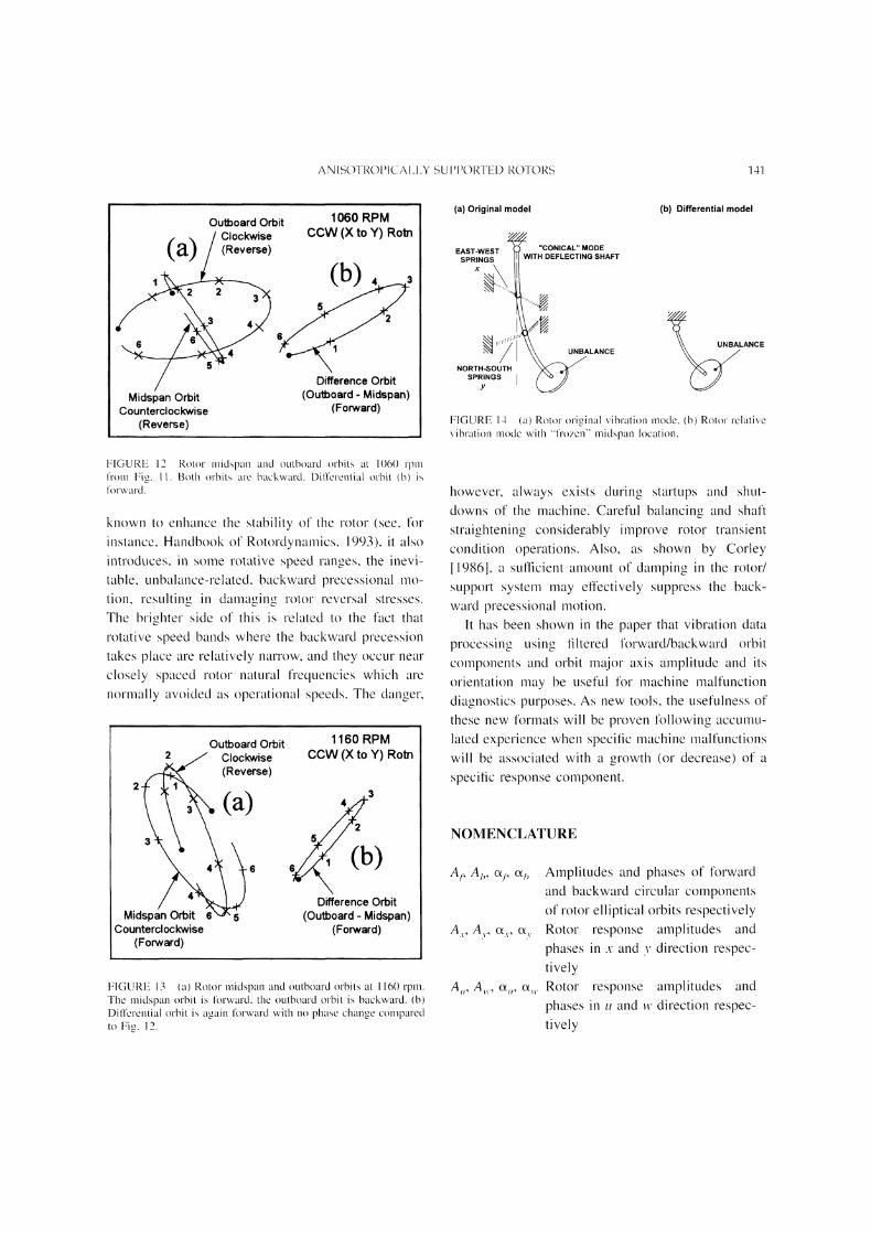
FIGURE 12 Rotor midspan and outboard orbits at 1()6()rpmfrom Fig. il. Both orbits are backward. Differential orbit (b)isforward.
known to enhance the stability of the rotor (see, forinstance, Handbook of Rotordynalnics, 1993), it alsointroduces, in some rotative speed ranges, the inevi-
table, unbalance-related, backward precessional mo-
tion, resultine in damaein- rotor reversal stresses
The brighter side of this is related to the fact thatrotative speed bands where the backward precessiontakes place are relatively narrow, and they occur near
closely spaced rotor natural frequencies which are
normally avoided as operational speeds. The danger,
Outboard Orbit
../ Clockwise
2, (Reverse)
Ca)
MidCounterclockwise
(Forward)
1160 RPMCCW (X to Y) Rotn
34
25
Difference Orbit(Outboard Midspan)
(Forward)
FIGURE 13 (a) Rotor midspan and outboard orbits at 1160 rpm.The midspan orbit is forward, the outboard orbit is backward. (b)Differential orbit is again lbrward with no phase change comparedto Fig. 12.
(a) Original model (b) Differential model
EAST-WESTSPRINGS
"CONICAL" MODEWITH DEFLECTING SHAFT
ANCEUNBALANCE
NORTH-SOUTHSPRINGS
FIGURE 14 (a) Rotor original vibration mode,(b) Rotor relative\’ibration mode with "frozen" rrlidspari location.
however, always exists during startups and shut-downs of the machine. Careful balancing and shaft
straiehtenin-,.. considerably improve rotor transient
condition operations. Also, as shown by Corley[19861, a sufficient amount of damping in the rotor/
support system may effectively suppress the back-ward precessional motion.
It has been shown in the paper that vibration data
processing using filtered forward/backward orbit
coinponents and orbit major axis amplitude and its
orientation may be useful for machine malfunction
diagnostics purposes. As new tools, the usefulness of
these new forlnats will be proven following acculnu-
lated experience when specific machine lnalfunctions
will be associated with a growth (or decrease) of a
specific response component.
NOMENCLATURE
AI; AI,, i o;, Amplitudes and phases of forwardand backward circular componentsof rotor elliptical orbits respectively
A.,., A,., o.,., c,. Rotor response amplitudes and
phases in .v and v direction respec-tively
A,,, A,., %,, o,,. Rotor response amplitudes and
phases in u and w direction respec-tively

142 A. MUSZYNSKA et al.
D Bearing or seal fluid radial damp-ing coefficient
D.,., M Rotor modal damping and mass re-
spectivelyF, m, External exciting nonsynchro-
nously rotating force amplitude,frequency, and angular orientation
respectivelyK,-, K,, Rotor/supporting structure stiff-
nesses in x and v directions
s,,, v 4 EigenvaluesS, o- Orbit major axis magnitude and its
angular orientationTime
u(t), w(t) Rotor lateral deflections in coordi-nates rotated by a constant angle e)
Rotor lateral deflections in two or-
thogonal directions
z..i(t), z,(t) Rotor forward and backward modevariables
X.,., X,. Fluid circumferential average ve-
locity ratios6) Coordinate or transducer rotation
angle(b, +2 Eigenfunctionst Rotative speed
x(t), 3,,(t)
ReferencesBentlv Nevada Mechanical Diagnostic Service Reports,
1989-1994.
Corley, J. E., 1986. The Importance of Being Stiff’: The Effects ofPedestal Stiffness on Rotor Dynamics, Vii)ration Inslitttte lOthAmutal Meeting Proceedings, Las Vegas, Nevada.
Gunter, E. J., Fang, Z., 1993. Forward and Backward CriticalSpeeds and Forced Response of an Overhung Rotor With Asym-metrical Bearing Supports, University of Virginia, School of En-gineering & Applied Science, Department of Mechanical &Aerospace Engineering.
Handbook q’Rotordynamics, 1993. Ed. F. E Ehrich, McGraw Hill,Inc., New York, Auckland, Bogota, Montreal, New Delhi.
Hatch, C. T., Bently, D. E., 1995. Anisotropic Rotor Response andProbe Data Transfommtion to Improve Machinery DiagnosticCapability," BRDRC Report No. 1/95.
Muszynska, A., 1988. Improvements in Lightly Loaded Rotor/
Bearing and Rotor/Seal Models, Trans. q[ the ASME, JournalVibration, Acoustics, Stress and Reliability in Design, v. I(LNo. 2.
Muszynska, A., 1989. Two-Mode Rotor With Anisotropic Supportsand Nonsymmetric Tangential Force, BRDRC Report No. 2/89.
Muszynska, A., 1994. Application of Multi-Mode Modal Models inRotor Dynamics, Proceedings q[" ISROMAC-5, Hawaii.
Muszynska, A., 1994. Forward and Backward Precession of a Ver-tical Anisotropically Supported Rotor, Journal q[ Sound and Vi-bration, Vol. 192.
Perez, G., Private communication.Vance, J. M., 1993. Rotmzh’namics q[’ Turbomachineo’, John Wiley& Sons, New York, Brisbane, Toronto, Singapore.
Xia, S., Wu, X., Wang, G., 1987. An Investigation of VibrationCharacteristics of Rotor and Rotor Support System for Locomo-tive Gas Turbine, Rotating Machinery Dynamics, ASME, Bos-toil.
Endnotes
1. Each of the two orthogonally oriented proximityprobes are actually located in horizontal planes. Theymeasure the vertical rotor lateral vibrations in two hor-izontal directions. Following, however, the oscillo-scope convention, these two lateral directions arecalled here "vertical" and "horizontal."
2. The direction of precession (orbiting) is indicated bythe sequence blank/bright (blank/dot) on the orbit.)

EENNEERRGGYY MMAATTEERRIIAALLSSMaterials Science & Engineering for Energy Systems
Economic and environmental factors are creating ever greater pressures for theefficient generation, transmission and use of energy. Materials developments arecrucial to progress in all these areas: to innovation in design; to extending lifetimeand maintenance intervals; and to successful operation in more demandingenvironments. Drawing together the broad community with interests in theseareas, Energy Materials addresses materials needs in future energy generation,transmission, utilisation, conservation and storage. The journal covers thermalgeneration and gas turbines; renewable power (wind, wave, tidal, hydro, solar andgeothermal); fuel cells (low and high temperature); materials issues relevant tobiomass and biotechnology; nuclear power generation (fission and fusion);hydrogen generation and storage in the context of the ‘hydrogen economy’; andthe transmission and storage of the energy produced.
As well as publishing high-quality peer-reviewed research, Energy Materialspromotes discussion of issues common to all sectors, through commissionedreviews and commentaries. The journal includes coverage of energy economicsand policy, and broader social issues, since the political and legislative contextinfluence research and investment decisions.
SSUUBBSSCCRRIIPPTTIIOONN IINNFFOORRMMAATTIIOONNVolume 1 (2006), 4 issues per year Print ISSN: 1748-9237 Online ISSN: 1748-9245Individual rate: £76.00/US$141.00Institutional rate: £235.00/US$435.00Online-only institutional rate: £199.00/US$367.00For special IOM3 member rates please emailssuubbssccrriippttiioonnss@@mmaanneeyy..ccoo..uukk
EEDDIITTOORRSSDDrr FFuujjiioo AAbbeeNIMS, Japan
DDrr JJoohhnn HHaalldd, IPL-MPT,Technical University ofDenmark, Denmark
DDrr RR VViisswwaannaatthhaann, EPRI, USA
FFoorr ffuurrtthheerr iinnffoorrmmaattiioonn pplleeaassee ccoonnttaacctt::Maney Publishing UKTel: +44 (0)113 249 7481 Fax: +44 (0)113 248 6983 Email: [email protected] Publishing North AmericaTel (toll free): 866 297 5154 Fax: 617 354 6875 Email: [email protected]
For further information or to subscribe online please visitwwwwww..mmaanneeyy..ccoo..uukk
CCAALLLL FFOORR PPAAPPEERRSSContributions to the journal should be submitted online athttp://ema.edmgr.com
To view the Notes for Contributors please visit:www.maney.co.uk/journals/notes/ema
Upon publication in 2006, this journal will be available via theIngenta Connect journals service. To view free sample contentonline visit: wwwwww..iinnggeennttaaccoonnnneecctt..ccoomm//ccoonntteenntt//mmaanneeyy
NNEEWW
FFOORR 22000066
Maney Publishing on behalf of the Institute of Materials, Minerals and Mining

International Journal of
AerospaceEngineeringHindawi Publishing Corporationhttp://www.hindawi.com Volume 2010
RoboticsJournal of
Hindawi Publishing Corporationhttp://www.hindawi.com Volume 2014
Hindawi Publishing Corporationhttp://www.hindawi.com Volume 2014
Active and Passive Electronic Components
Control Scienceand Engineering
Journal of
Hindawi Publishing Corporationhttp://www.hindawi.com Volume 2014
International Journal of
RotatingMachinery
Hindawi Publishing Corporationhttp://www.hindawi.com Volume 2014
Hindawi Publishing Corporation http://www.hindawi.com
Journal ofEngineeringVolume 2014
Submit your manuscripts athttp://www.hindawi.com
VLSI Design
Hindawi Publishing Corporationhttp://www.hindawi.com Volume 2014
Hindawi Publishing Corporationhttp://www.hindawi.com Volume 2014
Shock and Vibration
Hindawi Publishing Corporationhttp://www.hindawi.com Volume 2014
Civil EngineeringAdvances in
Acoustics and VibrationAdvances in
Hindawi Publishing Corporationhttp://www.hindawi.com Volume 2014
Hindawi Publishing Corporationhttp://www.hindawi.com Volume 2014
Electrical and Computer Engineering
Journal of
Advances inOptoElectronics
Hindawi Publishing Corporation http://www.hindawi.com
Volume 2014
The Scientific World JournalHindawi Publishing Corporation http://www.hindawi.com Volume 2014
SensorsJournal of
Hindawi Publishing Corporationhttp://www.hindawi.com Volume 2014
Modelling & Simulation in EngineeringHindawi Publishing Corporation http://www.hindawi.com Volume 2014
Hindawi Publishing Corporationhttp://www.hindawi.com Volume 2014
Chemical EngineeringInternational Journal of Antennas and
Propagation
International Journal of
Hindawi Publishing Corporationhttp://www.hindawi.com Volume 2014
Hindawi Publishing Corporationhttp://www.hindawi.com Volume 2014
Navigation and Observation
International Journal of
Hindawi Publishing Corporationhttp://www.hindawi.com Volume 2014
DistributedSensor Networks
International Journal of


![n']'W?:J, i'1w,ni'1 n'1:J37:J C'1Vn - אוניברסיטת ת"אrberman/papers/2012_Berman_Revisiting...131 Revisiting Roots in Hebrew: A Multi-faceted View coversroots occurringin](https://static.fdocuments.in/doc/165x107/5b409a137f8b9a91078d6aef/nwj-i1wni1-n1j37j-c1vn-rbermanpapers2012bermanrevisiting131.jpg)