DYNAMICS ME 34010 HOMEWORK...
126
DYNAMICS ME 34010 HOMEWORK SOLUTIONS Mahmoud M. Safadi 1 , M.B. Rubin 2 1 [email protected], 2 [email protected] Faculty of Mechanical Engineering Technion – Israel Institute of Technology Spring Semester 2016 Last revision: December 2017
Transcript of DYNAMICS ME 34010 HOMEWORK...

DYNAMICS
ME 34010
HOMEWORK SOLUTIONS
Mahmoud M. Safadi1, M.B. Rubin2
[email protected], [email protected]
Faculty of Mechanical Engineering
Technion – Israel Institute of Technology
Spring Semester 2016
Last revision: December 2017

Dynamics (ME 34010) Homework Solutions December 2017
Mahmoud M. Safadi 1 M.B. Rubin
Problem Set 1 Solutions
Problem 1
The vertical slotted guide shown in Fig. 1.1 moves horizontally at a speed 20 [mm s⁄ ].
This causes the pin 𝑃 to move in the fixed parabolic slot whose shape in given by
𝑦 =𝑥2
𝑏 , 𝑏 = 160 [mm] .
1. Find the velocity and acceleration of 𝑃.
2. Find the velocity and acceleration of the 𝑃 for the position 𝑥 = 60 [mm].
Figure 1.1
Solution:
The position of the particle is given by
𝒙 = 𝑥𝒆1 +𝑥2
𝑏𝒆2 .
Thus, the velocity of the particle becomes
𝒆2
𝒆1
𝑃
𝑥

Dynamics (ME 34010) Homework Solutions December 2017
Mahmoud M. Safadi 2 M.B. Rubin
𝒗 = �̇� = �̇� (𝒆1 +2𝑥
𝑏𝒆2) = 20𝒆1 +
𝑥
4𝒆2 [mm s⁄ ] .
Moreover, the acceleration of the particle takes the form
𝒂 = �̇� =2�̇�2
𝑏𝒆2 = 5𝒆2 [mm s2⁄ ] .
Next, at the instant when 𝑥 = 60 [mm], the velocity and acceleration of the particle are
given, respectively, by
𝒗 = 20𝒆1 + 15𝒆2 [mm s⁄ ] , 𝒂 = 5𝒆2 [mm s2⁄ ] .

Dynamics (ME 34010) Homework Solutions December 2017
Mahmoud M. Safadi 3 M.B. Rubin
Problem 2
The absolute acceleration vector of a particle, expressed in Cartesian coordinates with basis
vectors 𝒆𝑖, is given by
𝒂(𝑡) = (4𝑡 − 3)𝒆1 + 𝑡2𝒆2 [m s2⁄ ] .
The particle is initially (𝑡 = 0) at rest at the origin.
1. Find the velocity of the particle as a function of time.
2. Find the position of the particle as a function of time.
Solution:
The velocity of the particle is given by
𝒗(𝑡) = ∫ 𝑎(𝜏)𝑑𝜏𝑡
0
= [(2𝜏2 − 3𝜏)𝒆1 +𝜏3
3𝒆2]
0
𝑡
= (2𝑡2 − 3𝑡)𝒆1 +𝑡3
3𝒆2 [m s⁄ ].
Furthermore, the position of the particle takes the form
𝒙(𝑡) = ∫ 𝑣(𝜏)𝑑𝜏𝑡
0
= [(2𝜏3
3−3𝜏2
2)𝒆1 +
𝜏3
3𝒆2]
0
𝑡
= (2𝑡3
3−3𝑡2
2)𝒆1 +
𝑡3
3𝒆2 [m].

Dynamics (ME 34010) Homework Solutions December 2017
Mahmoud M. Safadi 4 M.B. Rubin
Problem 3
A particle passes through the points 𝐴: (1,1,1) [m] and 𝐵: (−1,4,7) [m] during its motion
along a straight line. Let 𝒆𝐵 𝐴⁄ denote the unit vector pointing from 𝐴 to 𝐵, and 𝑠(𝑡) the
distance traveled by the particle from the point 𝐴. The position vector of the particle is
given by
𝒙(𝑠) = 𝒙𝐴 + 𝑠𝒆𝐵 𝐴⁄ = 𝑥𝑖(𝑠)𝒆𝑖 [m] , 𝑖 = {1, 2, 3} ,
where the repeated index 𝑖 implies a summation over 𝑖 (Einstein summation convention).
1. Find the components 𝑥𝑖(𝑠) of 𝒙(𝑠).
2. Let 𝐶 denote the closest point to the origin along the straight line. Find the coordinates
of this point.
3. Find the distance between the point 𝐶 and the origin.
4. Find the distance between the points 𝐶 and 𝐵.
Solution:
The unit vector 𝒆𝐵 𝐴⁄ can be expressed as
𝒆𝐵 𝐴⁄ =𝒙𝐵 𝐴⁄
|𝒙𝐵 𝐴⁄ |=−2𝒆1 + 3𝒆2 + 6𝒆3
√49=1
7(−2𝒆1 + 3𝒆2 + 6𝒆3) .
Thus, the position vector 𝒙(𝑠) is given by
𝒙(𝑠) = (1 −2𝑠
7) 𝒆1 + (1 +
3𝑠
7)𝒆2 + (1 +
6𝑠
7) 𝒆3 [m] .
Now, the direction 𝒆𝐶 𝑂⁄ of 𝒙𝐶 𝑂⁄ is perpendicular to the direction 𝒆𝐵 𝐴⁄ of 𝒙(𝑠) provided
that 𝐶 is the closest point to the origin 𝑂 along 𝒙(𝑠). Denoting the coordinates of 𝐶 by
(𝑥1, 𝑥2, 𝑥3), it follows that
𝒆𝐵 𝐴⁄ ⋅ 𝒆𝐶 𝑂⁄ =1
7(−2𝒆1 + 3𝒆2 + 6𝒆3) ∙
1
√𝑥12 + 𝑥2
2 + 𝑥32(𝑥1𝒆1 + 𝑥2𝒆2 + 𝑥3𝒆3) = 0 ⇒

Dynamics (ME 34010) Homework Solutions December 2017
Mahmoud M. Safadi 5 M.B. Rubin
−2𝑥1 + 3𝑥2 + 6𝑥3 = 0 .
However, since 𝐶 lies on 𝒙(𝑠)
𝑥1 = 1 −2𝑠
7 , 𝑥2 = 1 +
3𝑠
7 , 𝑥3 = 1 +
6𝑠
7 .
Consequently,
−2(1 −2𝑠
7) + 3 (1 +
3𝑠
7) + 6 (1 +
6𝑠
7) = 7 +
49𝑠
7= 0 ⇒ 𝑠 = −1 [m] .
Moreover, the coordinates of 𝐶 are given by
𝒙𝐶 =1
7(9𝒆1 + 4𝒆2 + 𝒆3) [m] .
Next, the distances |𝒙𝐶 𝑂⁄ | and |𝒙𝐶 𝐵⁄ | are given, respectively, by
|𝒙𝐶 𝑂⁄ | = |𝒙𝐶| = √2 [m] , |𝒙𝐶 𝐵⁄ | = |𝒙𝐶 − 𝒙𝐵| = 8 [m] .

Dynamics (ME 34010) Homework Solutions December 2017
Mahmoud M. Safadi 6 M.B. Rubin
Problem 4
A moving object is influenced by the aerodynamic drag, which is proportional to the square
of the object’s speed, such that the acceleration of this object is given by
𝑎 = −𝑐1 − 𝑐2𝑣2 [m s2⁄ ] ,
where 𝑐1 [m s2⁄ ] and 𝑐2 [1 m⁄ ] are constant parameters.
The object starts its motion from the origin with speed 80 [km h⁄ ]. Furthermore, the speeds
of the object after traveling the distances of {200, 400} [m] are given, respectively, by
{60, 36} [km h⁄ ].
Find the total distance traveled until the object stops.
Solution:
Denoting the distance traveled by the object by 𝑥 and using the chain rule of differentiation
it follows that
𝑑𝑣
𝑑𝑡=𝑑𝑣
𝑑𝑥�̇� =
𝑑𝑣
𝑑𝑥𝑣 = 𝑎(𝑣) ⇒
𝑣
𝑎(𝑣)𝑑𝑣 = 𝑑𝑥 ⇒ 𝑥 = 𝑥0 +∫
𝑣
𝑎(𝑣)𝑑𝑣
𝑉
𝑣0
.
Now,
∫𝑣
𝑎(𝑣)𝑑𝑣
𝑉
𝑣0
= −∫𝑣
𝑐1 + 𝑐2𝑣2𝑑𝑣
𝑉
𝑣0
= −[1
2𝑐2ln(𝑐1 + 𝑐2𝑣
2)]𝑣0
𝑉
= −1
2𝑐2ln (
𝑐1 + 𝑐2𝑉2
𝑐1 + 𝑐2𝑣02) ,
such that
𝑥 = 𝑥0 −1
2𝑐2ln (
𝑐1 + 𝑐2𝑉2
𝑐1 + 𝑐2𝑣02) .
Next, with 𝑥0 = 0, 𝑣0 = 80 [km h⁄ ], and
@𝑥 = 0.2 [km]: 𝑉 = 60 [km h⁄ ] , @𝑥 = 0.4 [km]: 𝑉 = 36 [km h⁄ ] ,
it follows that

Dynamics (ME 34010) Homework Solutions December 2017
Mahmoud M. Safadi 7 M.B. Rubin
0.2 =1
2𝑐2ln (
𝑐1 + 3600𝑐2𝑐1 + 6400𝑐2
) , 0.4 =1
2𝑐2ln (
𝑐1 + 1296𝑐2𝑐1 + 6400𝑐2
) .
Solving these two equation for {𝑐1, 𝑐2} yields
𝑐1 = 4585 [km h⁄2] , 𝑐2 = 0.4874 [1 km⁄ ] .
Hence, the total distance traveled until the object stops is given by substituting the values
of {𝑐1, 𝑐2} together with {@𝑥 = 0.4 [km]: 𝑉 = 0} into 𝑥, such that
𝑥 = 0.5324 [km] = 532.4 [m] .

Dynamics (ME 34010) Homework Solutions December 2017
Mahmoud M. Safadi 8 M.B. Rubin
Problem Set 2 Solutions
Problem 1
Figure 2.1 shows a block being hauled to the surface over a curved track by a cable wound
around a 750 [mm] drum, which turns at the constant clockwise speed of 120 [rpm]. The
shape of the track is designed so that 𝑦 = 𝑥2 16⁄ , where 𝑥 and 𝑦 are in meters.
1. Determine the acceleration of the block as a function of 𝑥.
2. Find the magnitude of the acceleration of the block as it reaches a level of 1 [m] below
the top.
Figure 2.1
Solution:
The velocity of this block takes the form
𝒗 = �̇�𝒆𝑡 ,
where the speed �̇� of the block is given by
�̇� =𝜔𝐷
2 , 𝜔 = 120 [rpm] = 120 (
2𝜋
60) = 4𝜋 [rad s⁄ ] ⇒
�̇� = 2𝜋𝐷 [m s⁄ ] .
Moreover, the unit tangent vector can be expressed as
𝑥
𝑦
𝒆2
𝒆1
750 [mm]

Dynamics (ME 34010) Homework Solutions December 2017
Mahmoud M. Safadi 9 M.B. Rubin
𝒆𝑡 =𝑑𝒙
𝑑𝑠=𝑑𝒙
𝑑𝑥
𝑑𝑥
𝑑𝑠 , 𝒙 = 𝑥𝒆1 + 𝑦𝒆2 ,
𝑑𝑥
𝑑𝑠= −
1
√1 + (𝑑𝑦 𝑑𝑥⁄ )2 , 𝑦 =
𝑥2
16 ⇒
𝒆𝑡 = −1
√𝑥2 + 64(8𝒆1 + 𝑥𝒆2) .
Notice that the minus sign in 𝑑𝑥 𝑑𝑠⁄ must be included since each time 𝑠 increases, 𝑥
decreases (cf. Fig. 1.1). Therefore,
𝒗 = �̇�𝒆𝑡 = −2𝜋𝐷
√𝑥2 + 64(8𝒆1 + 𝑥𝒆2) .
Next, the acceleration of the block is given by
𝒂 = �̇� =𝑑𝒗
𝑑𝑥�̇� =
16𝜋𝐷�̇�
(𝑥2 + 64)3 2⁄(𝑥𝒆1 − 8𝒆2) , �̇� = −
�̇�
√1 + (𝑑𝑦𝑑𝑥)2
= −2𝜋𝐷
√1 +𝑥2
64
⇒
𝒂 =256𝜋2𝐷2
(𝑥2 + 64)2(−𝑥𝒆1 + 8𝒆2) .
Hence, as the block reaches a level of 1 [m] below the top it follows that the magnitude of
the acceleration of the block reduces to
𝑦 = 1 [m] ⇒ 𝑥 = 4 [m] ; 𝐷 = 0.75 [𝑚] ⇒
|𝒂| =256𝜋2(0.75)2
80√80≈ 1.986 [m s2⁄ ] .

Dynamics (ME 34010) Homework Solutions December 2017
Mahmoud M. Safadi 10 M.B. Rubin
Problem 2
The pin 𝑃 shown in Fig. 2.2 is constrained to move in the slotted guides 𝐴 and 𝐵 which
move at right angles to one another. At the instant represented, 𝐴 has a velocity to the right
of 0.2 [m s⁄ ] which is decreasing at the rate of 0.75 [m s⁄ ] each second. At the same time,
𝐵 is moving down with a velocity of 0.15 [m s⁄ ] which is decreasing at the rate of
0.5 [m s⁄ ] each second.
1. For this instant, find the radius of curvature 𝜌 of the path followed by 𝑃.
2. Is it possible to also determine the time rate of change of 𝜌.
Figure 2.2
Solution:
The velocity and acceleration of the pin 𝑃 are given, respectively, by
𝒗 = 0.2𝒆1 − 0.15𝒆2 [m s⁄ ] , 𝒂 = 0.75𝒆1 − 0.5𝒆2 [m s2⁄ ] .
Moreover, the unit tangent vector to the path followed by 𝑃 takes the form
𝒆𝑡 =𝒗
|𝒗|= 0.8𝒆1 − 0.6𝒆2 .
Therefore, the normal component of the acceleration of 𝑃 becomes
P
A
B
𝒆1
𝒆2

Dynamics (ME 34010) Homework Solutions December 2017
Mahmoud M. Safadi 11 M.B. Rubin
𝑎𝑛 = |𝒂 − (𝒂 ⋅ 𝒆𝑡)𝒆𝑡| = 0.05 [m s2⁄ ] .
Now, using the relation
𝑎𝑛 =�̇�2
𝜌=|𝒗|2
𝜌 ,
it follows that
𝜌 =|𝒗|2
𝑎𝑛 = 1.25 [m] .
Next, recall that the radius of curvature can be expressed in terms of the speed �̇� of 𝑃 and
the angular rate �̇� of the radial line from 𝑃 to the center of curvature in the form
�̇� = 𝜌�̇� .
Hence,
�̈� = �̇��̇� + 𝜌�̈� ⇒
�̇� =�̈� − 𝜌�̈�
�̇� ; �̈� = |𝒂 ⋅ 𝒆𝑡| , �̇� =
�̇�
𝜌 .
This shows that �̇� cannot be determined until the angular acceleration �̈� of the radial line
from 𝑃 to the center of curvature is known.

Dynamics (ME 34010) Homework Solutions December 2017
Mahmoud M. Safadi 12 M.B. Rubin
Problem 3
A particle is constrained to move along a track characterized by the function 𝑦 = 2𝑥3 2⁄ ,
where 𝑥 and 𝑦 are in meters. The distance 𝑠(𝑡) actually traveled by the particle as it moves
along the track is given by 𝑠(𝑡) = 2𝑡3, where 𝑡 denotes the time in seconds.
Initially, at the time 𝑡 = 0, 𝑥 = 0.
At the instant when 𝑡 = 1 [s]:
1. Find the radius of curvature of the particle path.
2. Find the magnitude of the acceleration of the particle.
Solution:
First, recall that
�̇� = �̇�√1 + (𝑑𝑦
𝑑𝑥)2
.
Hence,
6𝑡2 =𝑑𝑥
𝑑𝑡√1 + 9𝑥 ⇒ ∫ √1 + 9𝑥 𝑑𝑥
𝑥(1)
0
= ∫ 6𝑡2𝑑𝑡1
0
⇒ 2
27[1 + 9𝑥(1)]3 2⁄ = 2 ⇒
𝑥(1) =8
9 [𝑚] .
Next, the position, velocity, and acceleration of the particle at 𝑡 = 1[s] are given,
respectively, by
𝒙 = 𝑥𝒆1 + 2𝑥3 2⁄ 𝒆2 , 𝒗 = �̇�(𝒆1 + 3√𝑥𝒆2) , 𝒂 = �̈�𝒆1 + 3(�̈�√𝑥 +
�̇�2
2√𝑥)𝒆2 ,
where,
�̇� =�̇�
√1 + 9𝑥 =
6𝑡2
√1 + 9𝑥 , �̈� =
12𝑡
(1 + 9𝑥)1 2⁄ −
27�̇�
(1 + 9𝑥)2 ⇒

Dynamics (ME 34010) Homework Solutions December 2017
Mahmoud M. Safadi 13 M.B. Rubin
�̇�(1) = 2 [m s⁄ ] , �̈�(1) = 2 [m s⁄2] .
Therefore, the values of 𝒗 and 𝒂 at 𝑡 = 1 [s] reduce, respectively, to
𝒗(1) = 2𝒆1 + 4√2 𝒆2 [m s⁄ ] , 𝒂(1) = 2𝒆1 +17
√2𝒆2 [m s⁄
2] .
Next, the normal component of the acceleration of the particle at 𝑡 = 1 [s] takes the form
𝑎𝑛(1) = |𝒂 − (𝒂 ⋅ 𝒆𝑡)𝒆𝑡|𝑡=1 [s] , 𝒆𝑡(1) =𝒗(1)
|𝒗(1)|=1
3𝒆1 +
2√2
3𝒆2 ⇒
𝑎𝑛(1) =3√2
2 [m s⁄
2] ,
Consequently, the radius of curvature of the particle path is given by
𝜌(1) =|𝒗(1)|2
𝑎𝑛(1) = 12√2 [m] ≈ 17 [m] .

Dynamics (ME 34010) Homework Solutions December 2017
Mahmoud M. Safadi 14 M.B. Rubin
Problem 4
A particle moves in the 𝑥-𝑦 plane at constant speed 𝑏 along a track characterized by the
function 𝑦 = 𝑦(𝑥), where 𝑥 and 𝑦 are in meters. Also, let 𝑠 denote the actual distance
traveled by the particle along the track.
1. Assuming that 𝑑𝑥 𝑑𝑠⁄ > 0, show that
𝑑𝑠
𝑑𝑥= √1 + (
𝑑𝑦
𝑑𝑥)2
.
2. Use the chain rule of differentiation to determine the velocity of the particle as a
function of 𝑥.
3. Use the chain rule of differentiation to determine the acceleration of the particle as a
function of 𝑥.
4. Show that the radius of curvature at any point along the particle path is given by
𝜌 =
[1 + (𝑑𝑦𝑑𝑥)2
]
3 2⁄
𝑑2𝑦𝑑𝑥2
.
5. Determine the unit normal vector 𝒆𝑛 at any point along the particle path as a function
of 𝑥.
Solution:
Recall that the unit tangent vector 𝒆𝑡 is defined by
𝒆𝑡 =𝑑𝒙
𝑑𝑠 ; 𝒆𝑡 ⋅ 𝒆𝑡 = 1 , 𝒙 = 𝑥𝒆1 + 𝑦𝒆2 ,
so that
𝑑𝒙
𝑑𝑠⋅𝑑𝒙
𝑑𝑠= (
𝑑𝑥
𝑑𝑠)2
+ (𝑑𝑦
𝑑𝑠)2
= 1 ⇒ (𝑑𝑥)2 [1 + (𝑑𝑦
𝑑𝑥)2
] = (𝑑𝑠)2 ⇒

Dynamics (ME 34010) Homework Solutions December 2017
Mahmoud M. Safadi 15 M.B. Rubin
𝑑𝑠
𝑑𝑥= [1 + (
𝑑𝑦
𝑑𝑥)2
]
1 2⁄
.
Thus, the velocity of the particle is given by
𝒗 = �̇�𝒆𝑡 , 𝒆𝑡 =𝑑𝒙
𝑑𝑠=𝑑𝒙
𝑑𝑥 𝑑𝑥
𝑑𝑠= [1 + (
𝑑𝑦
𝑑𝑥)2
]
−1 2⁄
(𝒆1 +𝑑𝑦
𝑑𝑥𝒆2) ⇒
𝒗 = 𝑏 [1 + (𝑑𝑦
𝑑𝑥)2
]
−1 2⁄
(𝒆1 +𝑑𝑦
𝑑𝑥𝒆2)
Next, recall that the derivative of 𝒆𝑡 with respect to 𝑠 is given by
𝑑𝒆𝑡𝑑𝑠
=1
𝜌𝒆𝑛 ⇒ 𝜌 =
1
|𝑑𝒆𝑡𝑑𝑠|=
1
|𝑑𝒆𝑡𝑑𝑥
𝑑𝑥𝑑𝑠|=
[1 + (𝑑𝑦𝑑𝑥)2
]
1 2⁄
|𝑑𝒆𝑡𝑑𝑥|
,
where,
𝑑𝒆𝑡𝑑𝑥
= − [1 + (𝑑𝑦
𝑑𝑥)2
]
−3 2⁄𝑑𝑦
𝑑𝑥 𝑑2𝑦
𝑑𝑥2(𝒆1 +
𝑑𝑦
𝑑𝑥𝒆2) + [1 + (
𝑑𝑦
𝑑𝑥)2
]
−1 2⁄𝑑2𝑦
𝑑𝑥2𝒆2
= [1 + (𝑑𝑦
𝑑𝑥)2
]
−3 2⁄𝑑2𝑦
𝑑𝑥2(−
𝑑𝑦
𝑑𝑥 𝒆1 + 𝒆2) ,
Consequently,
𝜌 =
[1 + (𝑑𝑦𝑑𝑥)2
]
1 2⁄
[1 + (𝑑𝑦𝑑𝑥)2
]
−3 2⁄𝑑2𝑦𝑑𝑥2
[1 + (𝑑𝑦𝑑𝑥)2
]
1 2⁄=
[1 + (𝑑𝑦𝑑𝑥)2
]
3 2⁄
𝑑2𝑦𝑑𝑥2
.
Now, the acceleration of the particle takes the form
𝒂 = �̈�𝒆𝑡 +�̇�2
𝜌𝒆𝑛 =
𝑏2𝑑2𝑦𝑑𝑥2
[1 + (𝑑𝑦𝑑𝑥)2
]
3 2⁄ 𝒆𝑛 ,

Dynamics (ME 34010) Homework Solutions December 2017
Mahmoud M. Safadi 16 M.B. Rubin
where,
𝒆𝑛 = 𝜌𝑑𝒆𝑡𝑑𝑠
= 𝜌𝑑𝒆𝑡𝑑𝑥
𝑑𝑥
𝑑𝑠=
1
[1 + (𝑑𝑦𝑑𝑥)2
]
1 2⁄(−
𝑑𝑦
𝑑𝑥 𝒆1 + 𝒆2) ,
such that
𝒂 =𝑏2𝑑2𝑦𝑑𝑥2
[1 + (𝑑𝑦𝑑𝑥)2
]
2 (−𝑑𝑦
𝑑𝑥 𝒆1 + 𝒆2) .

Dynamics (ME 34010) Homework Solutions December 2017
Mahmoud M. Safadi 17 M.B. Rubin
Problem Set 3 Solutions
Problem 1
A particle moving along a curve in space has coordinates in millimeters which vary with
time 𝑡 in seconds according to
𝑥 = 60 cos(𝜔𝑡) , 𝑦 = 40 sin(𝜔𝑡) , 𝑧 = 30𝑡2 ,
where 𝜔 = 2 [rad s⁄ ].
1. Plot the path of the particle over the time interval 0 ≤ 𝑡 ≤ 20 [s].
At the instant when 𝑡 = 4 [s]:
2. Determine the unit normal and unit tangent vectors of the particle path.
3. Find the velocity of the particle.
4. Find the acceleration of the particle.
5. Find the radius of curvature of the particle path.
Solution:
The path of the particle is shown in Fig. 3.1. Now, the position of the particle is given by
𝒙 = 60 cos(𝜔𝑡) 𝒆1 + 40 sin(𝜔𝑡) 𝒆2 + 30𝑡2𝒆3 .
Hence, the unit tangent vector to the particle path can be expressed as
𝒆𝑡 =𝑑𝒙 𝑑𝑡⁄
|𝑑𝒙 𝑑𝑡⁄ |=−3𝜔 sin(𝜔𝑡) 𝒆1 + 2𝜔 cos(𝜔𝑡) 𝒆2 + 3𝑡𝒆3
√9𝑡2 + 𝜔2[9 − 5 cos(𝜔𝑡)] ,
such that
𝒆𝑡(4) = −0.443𝒆1 − 0.0434𝒆2 + 0.955𝒆3 .

Dynamics (ME 34010) Homework Solutions December 2017
Mahmoud M. Safadi 18 M.B. Rubin
Fig. 3.1
Also, the unit normal to the particle path is given by
𝒆𝑛 =𝑑𝒆𝑡 𝑑𝑡⁄
|𝑑𝒆𝑡 𝑑𝑡⁄ | .
However, it is more convenient to calculate 𝒆𝑛 using the acceleration of the particle as will
be shown next.
The velocity of the particle takes the form
𝒗 = −60𝜔 sin(𝜔𝑡) 𝒆1 + 40𝜔 cos(𝜔𝑡) 𝒆2 + 60𝑡𝒆3 ,
such that
𝒗(4) = −118.7𝒆1 − 11.64𝒆2 + 240𝒆3 [mm s⁄ ] .
Furthermore, the acceleration of the particle becomes
𝒂 = −60𝜔2 cos(𝜔𝑡) 𝒆1 − 40𝜔2 sin(𝜔𝑡) 𝒆2 + 60𝒆3 ,
such that
𝒂(4) = 34.92𝒆1 − 158.3𝒆2 + 60𝒆3 [mm s⁄2] .

Dynamics (ME 34010) Homework Solutions December 2017
Mahmoud M. Safadi 19 M.B. Rubin
Next, the normal component of the total acceleration at the time 𝑡 = 4 [s] is given by
𝒂𝑛(4) = [𝒂 − (𝒂 ⋅ 𝒆𝑡)𝒆𝑡]𝑡=4 [s] = 95.91𝒆1 − 156.3𝒆2 + 19.58𝒆3 [mm s⁄2] .
Thus, the unit normal vector to the particle path at the time 𝑡 = 4 [s] reduces to
𝒆𝑛 =𝒂𝑛(4)
|𝒂𝑛(4)|= 0.329𝒆1 − 0.937𝒆2 + 0.117𝒆3 .
Also, the radius of curvature of the particle path at the time 𝑡 = 4 [s] takes the form
𝜌 =|𝒗(4)|2
𝑎𝑛(4)= 430.5 [mm] .

Dynamics (ME 34010) Homework Solutions December 2017
Mahmoud M. Safadi 20 M.B. Rubin
Problem 2
Figure 3.2 shows a particle moving along a track inside a vertical cylinder of radius 2 [m].
At the instant represented, the particle passes through the point 𝐴 with an acceleration of
10 [m s2⁄ ] at an angle of 30o with respect to the horizontal plane, and it increases its speed
along the track at the rate of 8 [m s⁄ ] each second.
For this instant:
1. Determine the velocity of the particle in terms of cylindrical-polar coordinates.
2. Find the angular speed �̇� of the particle.
3. Find the angular acceleration �̈� of the particle.
4. Find the vertical component of the acceleration of the particle.
Figure 3.2
𝐴 30o 𝒆𝜃
𝒆3
𝒆𝑟
𝒆𝑡 𝑥3
𝑠
𝑟𝜃 𝒆𝜃
𝒆3 𝒆𝑡
30o

Dynamics (ME 34010) Homework Solutions December 2017
Mahmoud M. Safadi 21 M.B. Rubin
Solution:
The total |𝒂|, tangential |𝒂𝑡| and normal |𝒂𝑛| accelerations of the particle at the instant
represented in Fig. 3.2 are given, respectively, by
|𝒂| = 10 [m s⁄2] , |𝒂𝑡| = �̈� = 8 [m s⁄
2] , |𝒂𝑛| =
�̇�2
𝜌= √|𝒂|2 − |𝒂𝑡|2 = 6 [m s⁄
2] .
Moreover, the unit tangent vector to the particle path takes the form
𝒆𝑡 = cos(30𝑜) 𝒆𝜃 + sin(30𝑜) 𝒆3 =
√3
2𝒆𝜃 +
1
2𝒆3 ,
so that the corresponding unit normal vector reduces to
𝒆𝑛 ⋅ 𝒆𝑡 = 𝒆𝑛 ⋅ 𝒆3 = 0 ⇒ 𝒆𝑛 = −𝒆𝑟 .
Notice that the minus sign is taken since 𝒆𝑛 points toward the center of curvature.
Thus,
𝒂 = |𝒂𝑡|𝒆𝑡 + |𝒂𝑛|𝒆𝑛 = −6𝒆𝑟 + 4√3 𝒆𝜃 + 4𝒆3 .
Now, recall that the acceleration can be expressed in terms of cylindrical-polar coordinates
in the form
𝒂 = (�̈� − 𝑟�̇�2)𝒆𝑟 + (𝑟�̈� + 2�̇��̇�)𝒆𝜃 + �̈�3𝒆3 , 𝑟 = 2 [𝑚] , �̇� = 0 , �̈� = 0 ,
such that
−2�̇�2 = −6 ⇒ �̇� = √3 [rad s⁄ ] , 2�̈� = 4√3 ⇒ �̈� = 2√3 [rad s2⁄ ] ,
�̈�3 = 4 [m s2⁄ ] .
Next, using Fig. 1.1 it follows that
𝑠 =𝑟𝜃
cos(30o) ⇒ �̇� =
𝑟�̇�
cos(30o)=2√3
√3 2⁄= 4 [m s⁄ ] .
Consequently,
𝒗 = �̇�𝒆𝑡 = 2√3 𝒆𝜃 + 2𝒆3 [m s⁄ ] .

Dynamics (ME 34010) Homework Solutions December 2017
Mahmoud M. Safadi 22 M.B. Rubin
Problem 3
The cam shown in Fig. 3.3 is designed so that the center of the roller 𝐴 which follows the
contour moves on a limaçon defined by 𝑟 = 𝑏 − 𝑐 cos(𝛽), where 𝑏 > 𝑐 and 𝛽 is the angle
between the line 𝑂𝐵 fixed to the limaçon and the slotted arm. The base vectors {𝒆𝑟 , 𝒆𝜃} of
the polar coordinate system are fixed to the slotted bar. Moreover, take 𝑏 = 100 [mm] and
𝑐 = 75 [mm].
At the instant when 𝛽 = 30o:
1. Determine the total acceleration of the roller 𝐴 if the slotted arm revolves with a
constant counterclockwise angular speed of 40 [rpm] while the limaçon stays fixed.
2. Determine the total acceleration of the roller 𝐴 if the slotted arm stays fixed while the
limaçon revolves with a constant clockwise angular speed of 30 [rpm].
3. Determine the total acceleration of the roller 𝐴 if the slotted arm revolves with a
constant counterclockwise angular speed of 40 [rpm] while the limaçon revolves with
a constant clockwise angular speed of 30 [rpm].
Figure 3.3
𝒆𝑟
𝒆1
𝒆2
𝒆𝜃
30 [rpm] 𝛽
𝐴
𝑂
40 [rpm]
𝜃
𝐵 𝒆1′
𝒆2′
𝜙
𝜙

Dynamics (ME 34010) Homework Solutions December 2017
Mahmoud M. Safadi 23 M.B. Rubin
Solution:
Using the geometry in Fig. 3.3, the angle 𝜙 is related to the angles {𝜃, 𝛽} by
𝜙 = 𝛽 − 𝜃 ,
such that
�̇� = �̇� + �̇� .
Next, using this expression, the position, velocity and acceleration of the roller 𝐴 expressed
in terms of polar coordinates are given, respectively, by
𝒙 = [𝑏 − 𝑐 cos(𝛽)]𝒆𝑟 ,
𝒗 = 𝑐(�̇� + �̇�) sin(𝛽) 𝒆𝑟 + [𝑏 − 𝑐 cos(𝛽)]�̇�𝒆𝜃 ,
𝒂 = [𝑐 {(�̇� + �̇�)2+ �̇�2} cos(𝛽) − 𝑏�̇�2] 𝒆𝑟 + 2𝑐(�̇� + �̇�)�̇� sin(𝛽) 𝒆𝜃 .
Case 1:
�̇� = 40 [rpm] =4𝜋
3 [rad 𝑠⁄ ] , �̇� = 0 , 𝛽 = 30o ⇒
𝒂 = 0.525 𝒆𝑟 + 1.316 𝒆𝜃 [m s⁄2] .
Case 2:
�̇� = 0 , �̇� = −30 [rpm] = −𝜋 [rad 𝑠⁄ ] , 𝛽 = 30o ⇒
𝒂 = 0.641 𝒆𝑟 [m s⁄2] .
Case 3:
�̇� =4𝜋
3 [rad 𝑠⁄ ] , �̇� = −𝜋 [rad 𝑠⁄ ] , 𝛽 = 30o ⇒
𝒂 = −0.544 𝒆𝑟 + 0.329 𝒆𝜃 [m s⁄2] .

Dynamics (ME 34010) Homework Solutions December 2017
Mahmoud M. Safadi 24 M.B. Rubin
Problem 4
The hollow tube shown in Fig. 3.4 is inclined at an angle 𝛼 to the vertical axis and it rotates
along a circular path of radius 𝑅 with a constant angular speed about the vertical axis. A
particle 𝑃 moves inside the tube under the control of an inextensible string which is held
fixed at the point 𝐷. Moreover, the coordinate system 𝒆𝑖′ is fixed to the tube, the distance
traveled by the particle as it moves along the tube from the fixed point 𝐵 is denoted by 𝑠,
and the angle between the radial lines 𝑂𝐶 and 𝑂𝐷 is denoted by 𝜙.
Initially, at the time 𝑡 = 0, 𝜙 = 0 and 𝑠 = 0.
Figure 3.4
1. Determine the velocity of the particle 𝑃.
2. Determine the acceleration of the particle 𝑃.
3. Determine the velocity of the particle 𝑃 along the tube.
4. Determine the acceleration of the particle 𝑃 along the tube.
𝒆3 𝒆1′
𝒆3′
𝛼
𝜙
𝑂 𝐷
𝐶
𝑃
𝑠
𝐴
𝐵
𝑅

Dynamics (ME 34010) Homework Solutions December 2017
Mahmoud M. Safadi 25 M.B. Rubin
Solution:
The system 𝒆𝑖′ is defined by
�̇�𝑖′ = 𝝎 × �̇�𝑖 , 𝝎 = −�̇�𝒆3 , 𝒆3 = cos(𝛼) 𝒆1
′ + sin(𝛼) 𝒆3′ .
The angular speeds �̇� and �̇� can be related using the velocity 𝒗𝐶 of the upper end of the
hollow tube, such that
𝒙𝐶 𝐵⁄ = 𝐿𝒆1′ ⇒ 𝒗𝐶 = −�̇�[cos(𝛼) 𝒆1
′ + sin(𝛼) 𝒆3′ ] × 𝐿𝒆1
′ = −�̇�𝐿 sin(𝛼) 𝒆2′ ,
𝒙𝐶 𝑂⁄ = 𝑅[sin(𝜙) 𝒆1 + cos(𝜙) 𝒆2] ⇒ 𝒗𝐶 = 𝑅�̇�[cos(𝜙) 𝒆1 − sin(𝜙) 𝒆2] ,
where 𝐿 denotes the length of the tube, the unit vector 𝒆2 points rightward and the unit
vector 𝒆1 is defined by 𝒆1 = 𝒆2 × 𝒆3. Therefore,
�̇�𝐿 sin(𝛼) = 𝑅�̇� ⇒ �̇� =𝑅
𝐿 sin(𝛼)�̇� .
Now, using the geometry in Fig. 3.4 at the time 𝑡 = 0, i.e. when the upper end 𝐶 of the
hollow tube coincides with the fixed point 𝐷, it follows that
sin(𝛼) =𝑅
𝐿 .
Hence,
�̇� = �̇� .
Next, the velocity of the particle 𝑃 is given by
𝒙𝑃 𝐵⁄ = 𝒙𝑃 = 𝑠𝒆1′ ⇒ 𝒗𝑝 =
𝛿𝒙𝑃𝛿𝑡
+ 𝝎 × 𝒙𝑃 = �̇�𝒆1′ − �̇�𝑠 sin(𝛼) 𝒆2
′ .
However,
𝑠 = |𝒙𝐶 𝐷⁄ | = 2𝑅 sin (𝜙
2) ⇒ �̇� = 𝑅�̇� cos (
𝜙
2) ,
so that

Dynamics (ME 34010) Homework Solutions December 2017
Mahmoud M. Safadi 26 M.B. Rubin
𝒗𝑝 = 𝑅�̇� cos (𝜙
2) 𝒆1
′ − 2𝑅�̇� sin(𝛼) sin (𝜙
2) 𝒆2
′ .
Furthermore, using the Table 3.1,
𝒆1′ 𝒆2
′ 𝒆3′
𝝎 −�̇� cos(𝛼) 0 −�̇� sin(𝛼)
𝒗𝑃 𝑅�̇� cos (𝜙
2) −2𝑅�̇� sin(𝛼) sin (
𝜙
2) 0
𝛿𝒗𝑃 𝛿𝑡⁄ −𝑅�̇�2
2sin (
𝜙
2) −𝑅�̇�2 sin(𝛼) cos (
𝜙
2) 0
𝝎× 𝒗𝑃 −2𝑅�̇�2 sin2(𝛼) sin (𝜙
2) −𝑅�̇�2 sin(𝛼) cos (
𝜙
2) 𝑅�̇�2 sin(2𝛼) sin (
𝜙
2)
Table 3.1
the acceleration of the particle 𝑃,
𝒂𝑃 =𝛿𝒗𝑃𝛿𝑡
+ 𝝎 × 𝒗𝑃 ,
takes the form
𝒂𝑃 = −𝑅�̇�2 sin (𝜙
2) [1
2+ 2 sin2(𝛼)] 𝒆1
′ − 2𝑅�̇�2 sin(𝛼) cos (𝜙
2) 𝒆2
′
+ 𝑅�̇�2 sin(2𝛼) sin (𝜙
2) 𝒆3
′ .
Next, the velocity of the particle 𝑃 along the tube is given by
𝛿
𝛿𝑡[(𝒙𝑃 ⋅ 𝒆𝑖
′)𝒆𝑖′] =
𝛿
𝛿𝑡(𝑠𝒆1
′ ) = �̇�𝒆1′ = 𝑅�̇� cos (
𝜙
2) 𝒆1
′ .
Moreover, the acceleration of the particle 𝑃 along the tube takes the form
𝛿2
𝛿𝑡2[(𝒙𝑃 ⋅ 𝒆𝑖
′)𝒆𝑖′] =
𝛿
𝛿𝑡[𝑅�̇� cos (
𝜙
2) 𝒆1
′ ] = −𝑅�̇�2
2sin (
𝜙
2) 𝒆1
′ .

Dynamics (ME 34010) Homework Solutions December 2017
Mahmoud M. Safadi 27 M.B. Rubin
Problem Set 4 Solutions
Problem 1
The two ends 𝐶 and 𝐷 of the bar 𝐶𝐷 shown in Fig. 4.1 are confined to move in the rotating
slots of the right-angled frame 𝐴𝐵𝐹, which is hinged at 𝐵 to a car that moves to the right
with a constant speed 𝑣1. The angular speed of the frame about 𝐵 is �̇� and is constant for
the interval of motion concerned. Moreover, the whole system is accelerated upward with
a constant acceleration 𝑎0.
Initially, at the time 𝑡 = 0, 𝛾 = 𝜃 = 0o and the acceleration of the system is zero.
1. Determine the velocity of the midpoint 𝐸 of the bar 𝐶𝐷.
2. Determine the velocity of 𝐸 relative 𝐶.
3. Determine the acceleration of 𝐸.
Figure 4.1
𝒆1′
𝒆2′
𝒆1
𝒆2
𝑣1
𝑎0
𝐵
𝐷
𝐶
𝐸
𝛾
𝜃
𝐿 𝐴
𝐹

Dynamics (ME 34010) Homework Solutions December 2017
Mahmoud M. Safadi 28 M.B. Rubin
Solution:
The system 𝒆𝑖′ rotates with the angular velocity 𝝎, such that
�̇�𝑖′ = 𝝎× 𝒆𝑖
′ , 𝝎 = �̇�𝒆3 .
Now, the position of 𝐸 relative to 𝐵 is given by
𝒙𝐸 𝐵⁄ = 𝒙𝐶 𝐵⁄ + 𝒙𝐸 𝐶⁄ = 𝐿 cos(𝛾) 𝒆1′ +
𝐿
2[− cos(𝛾) 𝒆1
′ + sin(𝛾) 𝒆2′ ]
=𝐿
2[cos(𝛾) 𝒆1
′ + sin(𝛾) 𝒆2′ ] ,
so that the velocity of 𝐸 relative to 𝐵 becomes
𝒗𝐸 𝐵⁄ =𝛿𝒙𝐸 𝐵⁄
𝛿𝑡+ 𝝎 × 𝒙𝐸 𝐵⁄ =
(�̇� + �̇�)𝐿
2[− sin(𝛾) 𝒆1
′ + cos(𝛾) 𝒆2′ ] .
Moreover, the acceleration and velocity of 𝐵 take the forms
𝒂𝐵 = 𝑎0𝒆2 ⇒ 𝒗𝐵 = 𝒗𝐵(0) + 𝑎0𝑡𝒆2 = 𝑣1𝒆1 + 𝑎0𝑡𝒆2 .
Thus, the velocity of 𝐸 reduces to
𝒗𝐸 = 𝒗𝐵 + 𝒗𝐸 𝐵⁄ = 𝑣1𝒆1 + 𝑎0𝑡𝒆2 +(�̇� + �̇�)𝐿
2[− sin(𝛾) 𝒆1
′ + cos(𝛾) 𝒆2′ ] .
However,
𝒆1′ = cos(𝜃) 𝒆1 + sin(𝜃) 𝒆2 , 𝒆2
′ = −sin(𝜃) 𝒆1 + cos(𝜃) 𝒆2 ,
such that
𝒗𝐸 = [𝑣1 −(�̇� + �̇�)𝐿
2{sin(𝛾) cos(𝜃) + cos(𝛾) sin(𝜃)}] 𝒆1
+ [𝑎0𝑡 +(�̇� + �̇�)𝐿
2{cos(𝛾) cos(𝜃) − sin(𝛾) sin(𝜃)}] 𝒆2 .
Equivalently,
𝒗𝐸 = [𝑣1 −(�̇� + �̇�)𝐿
2sin(𝛾 + 𝜃)] 𝒆1 + [𝑎0𝑡 +
(�̇� + �̇�)𝐿
2cos(𝛾 + 𝜃)] 𝒆2 .

Dynamics (ME 34010) Homework Solutions December 2017
Mahmoud M. Safadi 29 M.B. Rubin
Furthermore, the acceleration 𝐸 takes the form
𝒂𝐸 = �̇�𝐸 = [−(�̇� + �̇�)
2𝐿
2cos(𝛾 + 𝜃)] 𝒆1 + [𝑎0 −
(�̇� + �̇�)2𝐿
2sin(𝛾 + 𝜃)] 𝒆2
Next, the position and velocity of 𝐶 relative to 𝐵 are given by
𝒙𝐶/𝐵 = 𝐿 cos(𝛾) 𝒆1′ ⇒ 𝒗𝐶/𝐵 =
𝛿𝒙𝐶/𝐵
𝛿𝑡+ 𝝎 × 𝒙𝐶/𝐵 = −�̇�𝐿 sin(𝛾) 𝒆1
′ + �̇�𝐿 cos(𝛾) 𝒆2′ .
Hence, the velocity of 𝐶 reduces to
𝒗𝐶 = 𝒗𝐵 + 𝒗𝐶/𝐵 = 𝑣1𝒆1 + 𝑎0𝑡𝒆2 − �̇�𝐿 sin(𝛾) 𝒆1′ + �̇�𝐿 cos(𝛾) 𝒆2
′ .
Using the transformation relations given previously, it follows that
𝒗𝐶 = [𝑣1 − �̇�𝐿 sin(𝛾) cos(𝜃) − �̇�𝐿 cos(𝛾) sin(𝜃)]𝒆1
+ [𝑎0𝑡 − �̇�𝐿 sin(𝛾) sin(𝜃) + �̇�𝐿 cos(𝛾) cos(𝜃)]𝒆2 .
Consequently, the velocity of 𝐸 relative to 𝐶 becomes
𝒗𝐸 𝐶⁄ = 𝐿 [−(�̇� + �̇�)
2sin(𝛾 + 𝜃) + �̇� sin(𝛾) cos(𝜃) + �̇� cos(𝛾) sin(𝜃)] 𝒆1
+ 𝐿 [(�̇� + �̇�)
2cos(𝛾 + 𝜃) + �̇� sin(𝛾) sin(𝜃) − �̇� cos(𝛾) cos(𝜃)] 𝒆2 .

Dynamics (ME 34010) Homework Solutions December 2017
Mahmoud M. Safadi 30 M.B. Rubin
Problem 2
A car at latitude 𝜆 on the rotating earth drives straight north with a constant speed 𝑣, as
shown in Fig. 4.2. The coordinate system 𝒆𝑖′′ is fixed to the earth which rotates about its
axis 𝒆2′′ once every 24 hours, and the coordinate system 𝒆𝑖
′ traces the motion of the car on
the surface of the earth.
Determine the acceleration of the car.
Figure 4.2
Solution:
The system {𝒆𝑖′′, 𝒆𝑖
′} rotate with the angular velocities {𝛀,𝝎}, respectively, such that
�̇�𝑖′′ = 𝛀 × 𝒆𝑖
′′ , 𝛀 = Ω𝒆2′′ ; �̇�𝑖
′ = 𝝎× 𝒆𝑖′ , 𝝎 = 𝛀 + λ̇𝒆2
′ = Ω𝒆2′′ + λ̇𝒆2
′ .
Also, these coordinate systems are related by
𝒆1′ = cos(𝜆) 𝒆1
′′ + sin(𝜆) 𝒆2′′ , 𝒆2
′ = −sin(𝜆) 𝒆1′′ + cos(𝜆) 𝒆2
′′ , 𝒆3′ = 𝒆3
′′ .
Next, the position 𝒙 of the car relative to the fixed origin 𝑂 should be expressed in terms
of the coordinate system 𝒆𝑖′′ since the velocity of the car relative to the earth is known and
given by
𝒆1′ 𝒆2
′
𝒆1′′
𝒆2′′
𝜆
𝒆3′
𝑣
Ω
𝑂

Dynamics (ME 34010) Homework Solutions December 2017
Mahmoud M. Safadi 31 M.B. Rubin
𝛿[(𝒙 ⋅ 𝒆𝑖′′)𝒆𝑖
′′]
𝛿𝑡= 𝑣𝒆2
′ = 𝑣[− sin(𝜆) 𝒆1′′ + cos(𝜆) 𝒆2
′′] .
To this end, denoting the radius of the earth by 𝑅⊕ it follows that
𝒙 = 𝑅⊕𝒆1′ = 𝑅⊕[cos(𝜆) 𝒆1
′′ + sin(𝜆) 𝒆2′′] ⇒
𝛿[(𝒙 ⋅ 𝒆𝑖′′)𝒆𝑖
′′]
𝛿𝑡= �̇�𝑅⊕[− sin(𝜆) 𝒆1
′′ + cos(𝜆) 𝒆2′′] .
Therefore,
�̇� =𝑣
𝑅⊕
.
Now, using Table 4.1,
𝒆1′′ 𝒆2
′′ 𝒆3′′
𝛀 0 Ω 0
𝒙 𝑅⊕ cos(𝜆) 𝑅⊕ sin(𝜆) 0
𝛿𝒙 𝛿𝑡⁄ −𝑣 sin(𝜆) 𝑣 cos(𝜆) 0
𝛀 × 𝒙 0 0 −Ω𝑅⊕ cos(𝜆)
𝒗 −𝑣 sin(𝜆) 𝑣 cos(𝜆) −Ω𝑅⊕ cos(𝜆)
𝛿𝒗 𝛿𝑡⁄ −𝑣2
𝑅⊕
cos(𝜆) −𝑣2
𝑅⊕
sin(𝜆) Ω𝑣 sin(𝜆)
𝛀 × 𝒗 −Ω2𝑅⊕ cos(𝜆) 0 Ω𝑣 sin(𝜆)
𝒂 −(𝑣2
𝑅⊕
+ Ω2) cos(𝜆) −𝑣2
𝑅⊕
sin(𝜆) 2Ω𝑣 sin(𝜆)
Table 4.1
the velocity and acceleration of the car are given, respectively, by
𝒗 = 𝑣[− sin(𝜆) 𝒆1′′ + cos(𝜆) 𝒆2
′′] − Ω𝑅⊕ cos(𝜆) 𝒆3′′ ,
𝒂 = −(𝑣2
𝑅⊕
+Ω2) cos(𝜆) 𝒆1′′ −
𝑣2
𝑅⊕
sin(𝜆) 𝒆2′′ + 2Ω𝑣 sin(𝜆) 𝒆3
′′ .

Dynamics (ME 34010) Homework Solutions December 2017
Mahmoud M. Safadi 32 M.B. Rubin
Problem 3
Consider the assembly shown in Fig. 4.3. The motor turns the disk at the constant speed �̇�.
The motor is also swiveling about the horizontal axis that passes through the point 𝐵 at the
constant speed �̇�. Simultaneously, the assembly is rotating about the vertical axis 𝒆2′′ at the
constant rate �̇�. The system 𝒆𝑖′ is fixed to the shaft 𝐵𝐶, such that {𝒆1
′ , 𝒆2′ , 𝒆2
′′} are always in
the same plane.
1. Determine the angular acceleration of the disk.
2. Determine the velocity and acceleration of the center 𝐶 of the disk.
Next, consider the point 𝑃 which is located at a distance 𝑅 from the center 𝐶 of the disk.
3. Determine the velocity and acceleration of 𝑃 relative to 𝐶.
4. Detertmine the velocity and acceleration of 𝑃.
Figure 4.3
𝒆1′
𝒆2′
𝒆2′
𝒆3′
𝜙 𝑃
𝐴
𝑏
𝐵 𝜃
𝑑
𝐶
𝑃
�̇� �̇�
𝒆2′′
𝑅

Dynamics (ME 34010) Homework Solutions December 2017
Mahmoud M. Safadi 33 M.B. Rubin
Solution:
The system {𝒆𝑖′′, 𝒆𝑖
′} rotate with the angular velocities {𝛀, 𝚲}, respectively, such that
�̇�𝑖′′ = 𝛀× 𝒆𝑖
′′ , 𝛀 = �̇�𝒆2′′ ; �̇�𝑖
′ = 𝚲 × 𝒆𝑖′ , 𝚲 = 𝛀 + �̇�𝒆3
′ = �̇�𝒆2′′ + �̇�𝒆3
′ .
Also, these coordinate systems are related by (see Fig. 4.4)
𝒆1′ = cos(𝜃) 𝒆1
′′ + sin(𝜃) 𝒆2′′ , 𝒆2
′ = −sin(𝜃) 𝒆1′′ + cos(𝜃) 𝒆2
′′ , 𝒆3′ = 𝒆3
′′ .
Therefore, the angular velocity 𝝎 of the disk is given by
𝝎 = �̇�𝒆1′ + 𝚲 = �̇�𝒆1
′ + �̇�𝒆2′′ + �̇�𝒆3
′ = �̇� cos(𝜃) 𝒆1′′ + [�̇� sin(𝜃) + �̇�]𝒆2
′′ + �̇�𝒆3′′ .
Moreover, using Table 4.2,
𝒆1′′ 𝒆2
′′ 𝒆3′′
𝛀 0 �̇� 0
𝝎 �̇� cos(𝜃) �̇� sin(𝜃) + �̇� �̇�
𝛿𝝎 𝛿𝑡⁄ −�̇��̇� sin(𝜃) �̇��̇� cos(𝜃) 0
𝛀 ×𝝎 �̇��̇� 0 −�̇��̇� cos(𝜃)
�̇� �̇�[�̇� − �̇� sin(𝜃)] �̇��̇� cos(𝜃) −�̇��̇� cos(𝜃)
Table 4.2
the angular acceleration �̇� of the disk takes the form
�̇� = �̇�[�̇� − �̇� sin(𝜃)]𝒆1′′ + �̇��̇� cos(𝜃) 𝒆2
′′ − �̇��̇� cos(𝜃) 𝒆3′′ .
Next, the position of the center 𝐶 of the disk is given by
𝒙𝐶 = 𝒙𝐵 + 𝒙𝐶 𝐵⁄ = 𝑏𝒆1′′ + 𝑑𝒆1
′ = [𝑏 + 𝑑 cos(𝜃)]𝒆1′′ + 𝑑 sin(𝜃) 𝒆2
′′
𝜃
𝜃
𝒆1′′
𝒆2′′
𝒆1′
𝒆2′
Figure 4.4

Dynamics (ME 34010) Homework Solutions December 2017
Mahmoud M. Safadi 34 M.B. Rubin
Thus, using Table 4.3,
𝒆1′′ 𝒆2
′′ 𝒆3′′
𝛀 0 �̇� 0
𝒙𝐶 𝑏 + 𝑑 cos(𝜃) 𝑑 sin(𝜃) 0
𝛿𝒙𝐶 𝛿𝑡⁄ −�̇�𝑑 sin(𝜃) �̇�𝑑 cos(𝜃) 0
𝛀 × 𝒙𝐶 0 0 −�̇�[𝑏 + 𝑑 cos(𝜃)]
𝒗𝐶 −�̇�𝑑 sin(𝜃) �̇�𝑑 cos(𝜃) −�̇�[𝑏 + 𝑑 cos(𝜃)]
𝛿𝒗𝐶 𝛿𝑡⁄ −�̇�2𝑑 cos(𝜃) −�̇�2𝑑 sin(𝜃) �̇��̇�𝑑 sin(𝜃)
𝛀× 𝒗𝐶 −�̇�2[𝑏 + 𝑑 cos(𝜃)] 0 �̇��̇�𝑑 sin(𝜃)
𝒂𝐶 −�̇�2[𝑏 + 𝑑 cos(𝜃)]
−�̇�2𝑑 cos(𝜃) −�̇�2𝑑 sin(𝜃) 2�̇��̇�𝑑 sin(𝜃)
Table 4.3
the velocity and acceleration of 𝐶 are given, respectively, by
𝒗𝐶 = −�̇�𝑑 sin(𝜃) 𝒆1′′ + �̇�𝑑 cos(𝜃) 𝒆2
′′ − �̇�[𝑏 + 𝑑 cos(𝜃)]𝒆3′′ ,
𝒂𝐶 = −[�̇�2{𝑏 + 𝑑 cos(𝜃)} + �̇�2𝑑 cos(𝜃)]𝒆1
′′ − �̇�2𝑑 sin(𝜃) 𝒆2′′ + 2�̇��̇�𝑑 sin(𝜃) 𝒆3
′′ .
Next, the position of the point 𝑃 relative to 𝐶 takes the form
𝒙𝑃 𝐶⁄ = 𝑅[cos(𝜙) 𝒆2′ + sin(𝜙) 𝒆3
′ ]
= 𝑅[− sin(𝜃) cos(𝜙) 𝒆1′′ + cos(𝜙) cos(𝜃) 𝒆2
′′ + sin(𝜙) 𝒆3′′] .
Equivalently,
𝒙𝑃 𝐶⁄ = 𝑅 [−1
2{sin(𝜃 + 𝜙) + sin(𝜃 − 𝜙)}𝒆1
′′ +1
2{cos(𝜃 + 𝜙) + cos(𝜃 − 𝜙)}𝒆2
′′
+ sin(𝜙) 𝒆3′′]
For convenience, denote
𝛼 = 𝜃 + 𝜙 , 𝛽 = 𝜃 − 𝜙 ,
such that
𝒙𝑃 𝐶⁄ = 𝑅 [−1
2{sin(𝛼) + sin(𝛽)}𝒆1
′′ +1
2{cos(𝛼) + cos(𝛽)}𝒆2
′′ + sin(𝜙) 𝒆3′′] .

Dynamics (ME 34010) Homework Solutions December 2017
Mahmoud M. Safadi 35 M.B. Rubin
Consequently, using Table 4.4, the velocity and acceleration of 𝑃 relative to 𝐶 are given,
respectively, by
𝒗𝑃 𝐶⁄ = 𝑅 [�̇� sin(𝜙) −�̇�
2cos(𝛼) −
�̇�
2cos(𝛽)] 𝒆1
′′ −𝑅
2[�̇� sin(𝛼) + �̇� sin(𝛽)]𝒆2
′′
+ 𝑅 [�̇� cos(𝜙) +�̇�
2{sin(𝛼) + sin(𝛽)}] 𝒆3
′′ ,
𝒂𝑃 𝐶⁄ = 𝑅 [�̇�2
2{sin(𝛼) + cos(𝛼)} +
�̇�2
2sin(𝛼) +
�̇�2
2sin(𝛽) + 2�̇��̇� cos(𝜙)] 𝒆1
′′
−𝑅
2[�̇�2 cos(𝛼) + �̇�2 cos(𝛽)]𝒆2
′′
+ 𝑅[(�̇�2 − �̇�2) sin(𝜙) + �̇��̇� cos(𝛼) + �̇��̇� cos(𝛽)]𝒆3′′ ,
with,
𝛼 = 𝜃 + 𝜙 , 𝛽 = 𝜃 − 𝜙 ; �̇� = �̇� + �̇� , �̇� = �̇� − �̇� .
Next, using the expressions for {𝒗𝐶 , 𝒗𝑃 𝐶⁄ , 𝒂𝐶 , 𝒂𝑃 𝐶⁄ } obtained previously, the velocity and
acceleration of 𝑃 become
𝒗𝑃 = 𝒗𝑃 𝐶⁄ + 𝒗𝐶 ; 𝒂𝑃 = 𝒂𝑃 𝐶⁄ + 𝒂𝐶 .

Dynamics (ME 34010) Homework Solutions December 2017
Mahmoud M. Safadi 36 M.B. Rubin
𝒆1′′ 𝒆2
′′ 𝒆3′′
𝛀 0 �̇� 0
𝒙𝑃 𝐶⁄ −𝑅
2sin(𝛼) −
𝑅
2sin(𝛽)
𝑅
2cos(𝛼) +
𝑅
2cos(𝛽) 𝑅 sin(𝜙)
𝛿𝒙𝑃 𝐶⁄ 𝛿𝑡⁄
−�̇�𝑅
2cos(𝛼)
−�̇�𝑅
2cos(𝛽)
−�̇�𝑅
2sin(𝛼)
−�̇�𝑅
2sin(𝛽)
�̇�𝑅 cos(𝜙)
𝛀 × 𝒙𝑃 𝐶⁄ �̇�𝑅 sin(𝜙) 0
�̇�𝑅
2sin(𝛼)
+�̇�𝑅
2sin(𝛽)
𝒗𝑃 𝐶⁄
−�̇�𝑅
2cos(𝛼)
−�̇�𝑅
2cos(𝛽)
+ �̇�𝑅 sin(𝜙)
−�̇�𝑅
2sin(𝛼)
−�̇�𝑅
2sin(𝛽)
�̇�𝑅 cos(𝜙)
+�̇�𝑅
2sin(𝛼)
+�̇�𝑅
2sin(𝛽)
𝛿𝒗𝑃 𝐶⁄ 𝛿𝑡⁄
�̇�2𝑅
2sin(𝛼)
+�̇�2𝑅
2sin(𝛽)
+ �̇��̇�𝑅 cos(𝜙)
−�̇�2𝑅
2cos(𝛼)
−�̇�2𝑅
2cos(𝛽)
−�̇�2𝑅 sin(𝜙)
+�̇��̇�𝑅
2cos(𝛼)
+�̇��̇�𝑅
2cos(𝛽)
𝛀 × 𝒗𝑃 𝐶⁄
�̇��̇�𝑅 cos(𝜙)
+�̇�2𝑅
2[sin(𝛼)
+ sin(𝛽)]
0
�̇��̇�𝑅
2cos(𝛼)
+�̇��̇�𝑅
2cos(𝛽)
+ �̇�2𝑅 sin(𝜙)
𝒂𝑃 𝐶⁄
�̇�2𝑅
2sin(𝛼)
+�̇�2𝑅
2sin(𝛽)
+ 2�̇��̇�𝑅 cos(𝜙)
+�̇�2𝑅
2[sin(𝛼)
+ cos(𝛼)]
−�̇�2𝑅
2cos(𝛼)
−�̇�2𝑅
2cos(𝛽)
−�̇�2𝑅 sin(𝜙)
+ �̇��̇�𝑅 cos(𝛼)
+ �̇��̇�𝑅 cos(𝛽)
+ �̇�2𝑅 sin(𝜙)
Table 4.4

Dynamics (ME 34010) Homework Solutions December 2017
Mahmoud M. Safadi 37 M.B. Rubin
Problem Set 5 Solutions
Problem 1
End 𝐴 of the rigid link 𝐴𝐵 is confined to move in the negative 𝒆1 direction while end 𝐵 is
confined to move along the vertical axis. Determine the component 𝝎𝑛 normal to 𝐴𝐵 of
the angular velocity of the link as it passes the position shown in Fig. 5.1 with the speed
𝑣𝐴 = 0.3 [m s⁄ ].
Figure 5.1
Solution:
The position and velocity of 𝐵 relative to 𝐴 are given, respectively, by
𝒙𝐵 𝐴⁄ = 0.6𝒆3 − (0.2𝒆1 + 0.3𝒆2) = −0.2𝒆1 − 0.3𝒆2 + 0.6𝒆3 [m] ,
𝒗𝐵 𝐴⁄ = 𝑣𝐵𝒆3 − (−0.3𝒆1) = 𝒗𝐵 𝐴⁄ = 0.3𝒆1 + 𝑣𝐵𝒆3 [m s⁄ ] .
Now, recall that 𝒗𝐵 𝐴⁄ is perpendicular to 𝒙𝐵 𝐴⁄ , i.e.,
𝒆3
𝒆2
𝒆1 300 [mm]
600 [mm] 700 [mm]
0.3 [m s⁄ ]
200 [mm]
𝐴
𝐵
𝑂

Dynamics (ME 34010) Homework Solutions December 2017
Mahmoud M. Safadi 38 M.B. Rubin
𝒗𝐵 𝐴⁄ ⋅ 𝒙𝐵 𝐴⁄ = 0 .
Therefore,
(0.3𝒆1 + 𝑣𝐵𝒆3) ⋅ (−0.2𝒆1 − 0.3𝒆2 + 0.6𝒆3) = 0 ⇒ 𝑣𝐵 = 0.1 [m s⁄ ] .
Furthermore,
𝒗𝐵 𝐴⁄ = 0.3𝒆1 + 0.1𝒆3 [m s⁄ ] .
Consequently, 𝝎𝑛 takes the form
𝝎𝑛 =𝒆𝐵 𝐴⁄ × 𝒗𝐵 𝐴⁄
|𝒙𝐵 𝐴⁄ |=𝒙𝐵 𝐴⁄ × 𝒗𝐵 𝐴⁄
|𝒙𝐵 𝐴⁄ |2 =
1
49(−3𝒆1 + 20𝒆2 + 9𝒆3) [rad s⁄ ] .

Dynamics (ME 34010) Homework Solutions December 2017
Mahmoud M. Safadi 39 M.B. Rubin
Problem 2
Determine the angular velocity of the telescoping link 𝐵𝐶 for the position shown in Fig.
5.2, where the driving links 𝐴𝐵 and 𝐶𝐷 have the angular velocities indicate.
Figure 5.2
Solution:
The velocities of 𝐵 and 𝐶 are given, respectively, by
𝒗𝐵 = 𝒗𝐵 𝐴⁄ = 𝝎𝐴𝐵 × 𝒙𝐵 𝐴⁄ = −0.5𝒆3 × 0.075𝒆1 = −0.0375𝒆2 [rad s⁄ ] ,
𝒗𝐶 = 𝒗𝐶 𝐷⁄ = 𝝎𝐶𝐷 × 𝒙𝐶 𝐷⁄ = −0.5𝒆3 × 0.1𝒆2 = 0.05𝒆1 [rad s⁄ ] .
Thus, the angular velocity 𝝎𝐵𝐶 of the telescoping link 𝐵𝐶 takes the form
𝝎𝐵𝐶 =𝒙𝐵 𝐶⁄ × 𝒗𝐵 𝐶⁄
|𝒙𝐵 𝐶⁄ |2 , 𝒙𝐵 𝐶⁄ = −0.225𝒆1 + 0.15𝒆2 [m] ,
𝒗𝐵 𝐶⁄ = −(0.05𝒆1 + 0.0375𝒆2) [rad s⁄ ] ⇒
𝝎𝐵𝐶 = 0.218𝒆3 [rad s⁄ ] .
𝒆1
𝒆2
300 [mm]
250 [mm] 100 [mm]
75 [mm]
0.5 [rad s⁄ ]
0.5 [rad s⁄ ]
𝐴 𝐵
𝐶
𝐷

Dynamics (ME 34010) Homework Solutions December 2017
Mahmoud M. Safadi 40 M.B. Rubin
Problem 3
The slotted wheel of radius 𝑅 = 60 [cm] shown in Fig. 5.3 rolls on the horizontal plane in
a circle of radius 𝐿 = 60 [cm]. The wheel shaft 𝐵𝐶 is pivoted about an axis through the
point 𝐵 at one end, and is driven by the vertical shaft at the constant rate �̇� = 4 [rad s⁄ ]
about the vertical axis. The slider 𝑃 moves in the slot and its radial distance relative to the
center of the disk is denoted by 𝑠(𝑡). The system {𝒆𝑖′′, 𝒆𝑖
′} are fixed to 𝐵𝐶 and the wheel,
respectively, and they are always in the same plane with 𝜃 denoting the angle between the
axes 𝒆1′ and 𝒆1
′′.
1. Determine the angular velocity of the disk.
2. Determine the angular velocity of the disk for the position 𝜃 = 30o.
3. Determine the velocity and acceleration of the slider 𝑃.
Figure 5.3
𝐿 = 60 [cm]
𝑅 = 60 [cm]
𝐵
𝐴
𝐶 𝑃
𝑠(𝑡)
𝒆1′′
�̇� = 4 [rad s⁄ ]
𝒆2′′, 𝒆2
′
𝒆1′′
𝒆1′
𝒆3′
𝜃
𝒆3′′
𝐸
𝐷 𝐸

Dynamics (ME 34010) Homework Solutions December 2017
Mahmoud M. Safadi 41 M.B. Rubin
Solution:
Let {𝝎,𝛀} denote the angular velocities of the wheel and its shaft, respectively, such that
�̇�𝑖′′ = 𝛀 × 𝒆𝑖
′′ , 𝛀 = �̇�𝒆1′′ ,
�̇�𝑖′ = 𝝎× 𝒆𝑖
′ , 𝛚 = 𝛀 + �̇�𝒆2′′ = �̇�𝒆1
′′ + �̇�𝒆2′′ ,
where �̇� is angular speed of the wheel relative to 𝐵𝐶.
Next, since the wheel rolls without slipping on the horizontal plane, it follows that the
velocity 𝒗𝐸 𝐸′⁄ of the point 𝐸 fixed to the disk relative to the point 𝐸′ fixed to the horizontal
plane vanishes, such that
𝒗𝐸 𝐸′⁄ = 𝟎 , 𝒗𝐸′ = 𝟎 ⇒ 𝒗𝐸 = 𝟎 .
Moreover, 𝒗𝐸 can be expressed as
𝒗𝐸 = 𝒗𝐶 +𝝎× 𝒙𝐸 𝐶⁄ ,
where,
𝒗𝐶 = 𝒗𝐶 𝐵⁄ = 𝛀 × 𝒙𝐶 𝐵⁄ = �̇�𝑒1′′ × 𝐿𝒆2
′′ = �̇�𝐿𝒆3′′ .
Therefore,
𝒗𝐸 = �̇�𝐿𝒆3′′ + (�̇�𝒆1
′′ + �̇�𝒆2′′) × (−𝑅𝒆1
′′) = (�̇�𝐿 + �̇�𝑅)𝒆3′′ = 𝟎 ⇒
�̇� = −�̇�𝐿
𝑅= −4 [rad s⁄ ] .
Substituting this value into 𝝎 yields
𝝎 = 4(𝒆1′′ − 𝒆2
′′) [rad s⁄ ] .
Furthermore, expressing 𝝎 in terms of the coordinate system 𝒆𝑖′, it follows that
𝝎 = 4[cos(𝜃) 𝒆1′ − 𝒆2
′ − sin(𝜃) 𝒆3′ ] [rad s⁄ ] .
Hence, the value 𝝎(30o) of 𝝎 at the position 𝜃 = 30o is given by

Dynamics (ME 34010) Homework Solutions December 2017
Mahmoud M. Safadi 42 M.B. Rubin
𝝎(30o) = 4(√3
2𝒆1′ − 𝒆2
′ −1
2𝒆3′ ) [rad s⁄ ] .
Next, the velocity 𝒗𝑃 and acceleration 𝒂𝑃 of the slider 𝑃 take the forms
𝒗𝑃 = 𝒗𝐶 + 𝒗𝑃 𝐶⁄ , 𝒗𝐶 = �̇�𝐿𝒆3′′ ;
𝒂𝑃 = 𝒂𝐶 + 𝒂𝑃 𝐶⁄ , 𝒂𝐶 = �̇�𝐿(�̇�𝒆1′′ × 𝒆3
′′) = −�̇�2𝐿𝒆2′′ .
where the velocity 𝒗𝑃 𝐶⁄ and acceleration 𝒂𝑃 𝐶⁄ of 𝑃 relative to 𝐶 are given in Table 5.1.
𝒆1′′ 𝒆2
′′ 𝒆3′′
𝛀 �̇� 0 0
𝒙𝑃 𝐶⁄ 𝑠 cos(𝜃) 𝑠 sin(𝜃) 0
𝛿𝒙𝑃 𝐶⁄ 𝛿𝑡⁄ �̇� cos(𝜃) − �̇�𝑠 sin(𝜃) �̇� sin(𝜃) + �̇�𝑠 cos(𝜃) 0
𝛀 × 𝒙𝑃 𝐶⁄ 0 0 �̇�𝑠 sin(𝜃)
𝒗𝑃 𝐶⁄ �̇� cos(𝜃) − �̇�𝑠 sin(𝜃) �̇� sin(𝜃) + �̇�𝑠 cos(𝜃) �̇�𝑠 sin(𝜃)
𝛿𝒗𝑃 𝐶⁄ 𝛿𝑡⁄ (�̈� − �̇�2𝑠) cos(𝜃)
− (�̈�𝑠 + 2�̇��̇�) sin(𝜃)
(�̈� − �̇�2𝑠) sin(𝜃)
+ (�̈�𝑠 + 2�̇��̇�) cos(𝜃)
�̇�[�̇� sin(𝜃)
+ �̇�𝑠 cos(𝜃)]
𝛀 × 𝒗𝑃 𝐶⁄ 0 −�̇�2𝑠 sin(𝜃) �̇�[�̇� sin(𝜃)
+ �̇�𝑠 cos(𝜃)]
𝒂𝑃 𝐶⁄ (�̈� − �̇�2𝑠) cos(𝜃)
− (�̈�𝑠 + 2�̇��̇�) sin(𝜃)
[�̈� − (�̇�2 + �̇�2)𝑠] sin(𝜃)
+ (�̈�𝑠 + 2�̇��̇�) cos(𝜃)
2�̇�[�̇� sin(𝜃)
+ �̇�𝑠 cos(𝜃)]
Table 5.1

Dynamics (ME 34010) Homework Solutions December 2017
Mahmoud M. Safadi 43 M.B. Rubin
Problem 4
The hollow curved member 𝑂𝐸 shown in Fig. 5.4 rotates counterclockwise at a constant
rate �̇� = 2 [rad s⁄ ], and the pin 𝐴 causes the link 𝐵𝐶 to rotate as well. For the instant when
𝜃 = 30o , 𝛽 = 45o , 𝐻 = 280 [mm] , 𝐿 = 120 [mm] ,
where 𝛽 is the angle between the vertical axis and the tangent to 𝑂𝐸 at 𝐴, determine the
velocity of end 𝐵 of the link 𝐵𝐶.
Solution:
The velocity of the pin 𝐴 fixed to the link 𝐵𝐶 is given by
𝒙𝐴/𝐶 = 𝐿[sin(𝜃) 𝒆1 − cos(𝜃) 𝒆2] ⇒ 𝒗𝐴 = �̇�𝐿[cos(𝜃) 𝒆1 + sin(𝜃) 𝒆2] .
On the other hand, the velocity 𝒗𝐴′ of the point 𝐴′ fixed to the curved member 𝑂𝐸 which
is instantaneously in contact with 𝐴 takes the form
𝒙𝐴′/𝑂 = 𝒙𝐶 𝑂⁄ + 𝒙𝐴′ 𝐶⁄ = 𝐿 sin(𝜃) 𝒆1 + [𝐻 − 𝐿 cos(𝜃)]𝒆2 ⇒
𝒗𝐴′ = �̇�𝒆3 × 𝒙𝐴/𝑂 = �̇�[−{𝐻 − 𝐿 cos(𝜃)}𝒆1 + 𝐿 sin(𝜃) 𝒆2] .
Next, since the pin 𝐴 is confined to move along 𝑂𝐸, it follows that
𝜃
𝛽
𝐻
𝒆1
𝒆2
𝐶
𝑂
𝐵
𝐴
𝐿
𝐿
𝐸
Figure 5.4

Dynamics (ME 34010) Homework Solutions December 2017
Mahmoud M. Safadi 44 M.B. Rubin
𝒗𝐴/𝐴′ ⋅ 𝒏 = 0 ,
where 𝒏 is the unit normal to 𝑂𝐸 at 𝐴. Therefore, with the help of the unit tangent 𝒕 to 𝑂𝐸
at 𝐴, i.e.,
𝒕 = cos(𝛽) 𝒆1 + sin(𝛽) 𝒆2 ,
it follows that
𝒏 = 𝒆3 × 𝒕 = − sin(𝛽) 𝒆1 + cos(𝛽) 𝒆2 .
Consequently, the angular speed �̇� of the link 𝐵𝐶 is given by
−[�̇�𝐿 cos(𝜃) + �̇�{𝐻 − 𝐿 cos(𝜃)}] sin(𝛽) + [�̇�𝐿 sin(𝜃) − �̇�𝐿 sin(𝜃)] cos(𝛽) = 0 ⇒
�̇� = −�̇� [sin(𝜃) + {
𝐻𝐿 − cos
(𝜃)} tan(𝛽)
cos(𝜃) tan(𝛽) − sin(𝜃)] = −10.75 [rad s⁄ ] .
Next, the velocity 𝒗𝐵 of end 𝐵 of the link 𝐵𝐶 takes the form
𝒙𝐵/𝐶 = 2𝐿[sin(𝜃) 𝒆1 − cos(𝜃) 𝒆2] ⇒
𝒗𝐵 = 2�̇�𝐿[cos(𝜃) 𝒆1 + sin(𝜃) 𝒆2] = −2.234𝒆1 − 1.290𝒆2 [m s⁄ ] .

Dynamics (ME 34010) Homework Solutions December 2017
Mahmoud M. Safadi 45 M.B. Rubin
Problem Set 6 Solutions
Problem 1
Fig. 6.1 shows an astronaut training facility. The drum swivels about the horizontal axis
𝒆1′′ that passes through the hinge 𝐴 at the rate �̇�. The training room is located inside the
drum and it rotates about the axis 𝒆1′ at the rate �̇�. Simultaneously, the training facility
rotates about the vertical axis 𝒆2′′ at the rate Ω . At the instant when
𝛽 = 0 , �̇� = 0.9 [rad s⁄ ] , Ω = 0.2 [rad s⁄ ] , �̇� = 0.9 [rad s⁄ ] ,
determine the angular velocity and acceleration of the training room.
Figure 6.1
𝒆1′′
𝒆2′′
𝒆1′
𝒆2′
𝛽
�̇�
Ω
𝐴
Drum

Dynamics (ME 34010) Homework Solutions December 2017
Mahmoud M. Safadi 46 M.B. Rubin
Solution:
Let {𝛀,𝝎} denote the angular velocities of the coordinate systems {𝒆𝑖′′, 𝒆𝑖
′}, such that
�̇�𝑖′′ = 𝛀 × 𝒆𝑖
′′ , 𝛀 = Ω𝒆2′′ ; �̇�𝑖
′ = 𝝎× 𝒆𝑖′ , 𝝎 = 𝛀 + �̇�𝒆3
′ = Ω𝒆2′′ + �̇�𝒆3
′ .
Moreover, these coordinate systems are related by
𝒆1′ = cos(𝛽) 𝒆1
′′ + sin(𝛽) 𝒆2′′ , 𝒆2
′ = −sin(𝛽) 𝒆1′′ + cos(𝛽) 𝒆2
′′ , 𝒆3′ = 𝒆3
′′ .
Next, the angular velocity 𝚲 of the training room takes the form
𝚲 = 𝝎 + �̇�𝒆1′ = �̇�𝒆1
′ + Ω𝒆2′′ + �̇�𝒆3
′ = �̇� cos(𝛽) 𝒆1′′ + [Ω + �̇� sin(𝛽)]𝒆2
′′ + �̇�𝒆3′′ .
Substituting the values given previously, it follows that
𝛀 = 0.9𝒆1′′ + 0.2𝒆2
′′ + 0.9𝒆3′′ [rad s⁄ ] .
Now, using Table 6.1,
𝒆1′′ 𝒆2
′′ 𝒆3′′
𝛀 0 Ω 0
𝚲 �̇� cos(𝛽) Ω + �̇� sin(𝛽) �̇�
𝛿𝚲 𝛿𝑡⁄ �̈� cos(𝛽)
− �̇��̇� sin(𝛽)
Ω̇ + �̈� sin(𝛽)
+ �̇��̇� cos(𝛽) �̈�
𝛀 × 𝚲 Ω�̇� 0 −Ω�̇� cos(𝛽)
�̇� �̈� cos(𝛽)
− �̇��̇� sin(𝛽) + Ω�̇�
Ω̇ + �̈� sin(𝛽)
+ �̇��̇� cos(𝛽) �̈� − Ω�̇� cos(𝛽)
Table 6.1
the angular velocity �̇� of the training room becomes
�̇� = 0.18𝒆1′′ + 0.81𝒆2
′′ − 0.18𝒆3′′ [rad s2⁄ ] .
where use has been made of the values given previously.

Dynamics (ME 34010) Homework Solutions December 2017
Mahmoud M. Safadi 47 M.B. Rubin
Problem 2
The 20 [kg] block 𝐴 is placed on top of the 100 [kg] block 𝐵, as shown in Fig. 6.2. Block
𝐴 is being pulled horizontally by a rope with a pull magnitude of 𝑃. If the coefficient of
static and kinetic friction between the two blocks are both essentially the same value of
0.5, and the horizontal plane is frictionless:
1. Plot the acceleration of each block as a function of 𝑃.
2. Determine the acceleration of each block for 𝑃 = 60 [N] and 𝑃 = 40 [N].
Figure 6.2
Solution:
Figure 6.3
𝑔
𝑃 𝐴
𝐵
20 [kg]
100 [kg]
20𝑔
100𝑔
𝑅
𝐴
𝐵
𝐴
𝐵
2𝑃 2𝑃
20𝑔
100𝑔
𝑃
𝑁
𝑓
𝑓
𝑁
𝒆2
𝒆1
(a) (b)

Dynamics (ME 34010) Homework Solutions December 2017
Mahmoud M. Safadi 48 M.B. Rubin
The two blocks move with the same acceleration before block 𝐴 starts slipping on top of
block 𝐵, as shown in Fig. 6.3a. Denoting the acceleration of the system by 𝑎 it follows
from the balance of linear momentum that
2𝑃𝒆1 + (𝑅 − 120𝑔)𝒆2 = 120𝑎𝒆1 ⇒
𝑅 = 1200 [N] , 𝑎 = 𝑃 60⁄ ≈ 0.0167𝑃 [m s2⁄ ] .
Next, Fig. 6.3b shows the free body diagram of each block when 𝐴 is slipping on top of 𝐵.
Denoting the accelerations of {𝐴, 𝐵} by {𝑎𝐴, 𝑎𝐵}, respectively, it follows from the balance
of linear momentum that
(2𝑃 − 𝑓)𝒆1 + (𝑁 − 20𝑔)𝒆2 = 20𝑎𝐴 , 𝑓 = 𝜇𝑁 ⇒
𝑁 = 20𝑔 = 200 [N] , 𝑎𝐴 = 0.1𝑃 − 4.905 [m s2⁄ ] ,
and,
𝑓𝒆1 + (𝑃 − 𝑁 − 100𝑔)𝒆2 = 100𝑎𝐵 , 𝑓 = 𝜇𝑁 ⇒
𝑃 = 1200 [N] , 𝑎𝐵 = 0.981 [m s2⁄ ] .
Now, the continuity of the accelerations yields
𝑎𝐴 = 𝑎 and 𝑎𝐵 = 𝑎 ⇒ 𝑃 = 58.86 [N] .
The plots of {𝑎𝐴, 𝑎𝐵} as functions of 𝑃 are shown in Fig. 6.4.
Fig. 6.4
𝑃 [N]
𝑎 [m s2⁄ ]
𝑎𝐴 𝑎𝐵
58.86
0.981

Dynamics (ME 34010) Homework Solutions December 2017
Mahmoud M. Safadi 49 M.B. Rubin
Next, assuming that 𝐴 does not slip on top of 𝐵, it follows from the balance of linear for
each block that
(2𝑃 − 𝑓)𝒆1 + (𝑁 − 20𝑔)𝒆2 = 20𝑎 ⇒ 𝑁 = 196.2 [N] , 2𝑃 − 𝑓 = 20𝑎 ,
and,
𝑓𝒆1 + (𝑃 − 𝑁 − 100𝑔)𝒆2 = 100𝑎 ⇒ 𝑃 = 1177.2 [N] , 𝑓 = 100𝑎 .
Solving these equations for 𝑓 yields
𝑓 = 5𝑃 3⁄ ≈ 1.667𝑃 .
Moreover, since friction is static in this case,
𝑓 ≤ 𝜇𝑠𝑁 ⇒ 𝑃 ≤ 58.86 [N] .
Consequently, for 𝑃 = 60 [N], block 𝐴 slips on top of block 𝐵, so that
𝑎𝐴 = 0.1(60) − 4.905 = 1.095 [m s2⁄ ] , 𝑎𝐵 = 0.01𝜇𝑁 = 0.981 [m s2⁄ ] .
Also, for 𝑃 = 40 [N], block 𝐴 does not slip on top of block 𝐵, so that
𝑎𝐴 = 𝑎𝐵 = 𝑎 = 0.667 [m s2⁄ ] .

Dynamics (ME 34010) Homework Solutions December 2017
Mahmoud M. Safadi 50 M.B. Rubin
Problem 3
The sliders 𝐴 and 𝐵 are connected by a light rigid bar of length 𝑙 = 0.5 [m] and move in
the slots shown in Fig. 6.5. The slider 𝐴 is being pulled horizontally by a constant force of
magnitude 𝑃 = 40 [𝑁]. For the position where 𝑥𝐴 = 0.4 [m], the velocity of 𝐴 is given by
𝑣𝐴 = 0.9 [m s⁄ ] to the right. At this instant:
1. Determine the acceleration of each slider.
2. Determine the force in the bar.
Figure 6.5
Solution:
The velocities of 𝐴 and 𝐵 are given, respectively, by
𝒗𝐴 = �̇�𝒆1 , 𝒗𝐵 = −�̇�𝒆2 ,
Moreover, {�̇�, �̇�} are related to {�̇�𝐴, �̇�𝐵} by
�̇� = �̇�𝐴 , �̇� = −�̇�𝐵 ; �̈� = �̈�𝐴 , �̈� = −�̈�𝐵 .
Moreover, using the geometry in Fig. 6.5, then
𝐵
𝐴 𝑃 = 40 [N]
3 [kg]
2 [kg]
𝑙 = 0.5 [m]
𝑥𝐴
𝒆2
𝒆1
𝑦𝐵
𝑦
𝑥

Dynamics (ME 34010) Homework Solutions December 2017
Mahmoud M. Safadi 51 M.B. Rubin
𝑥𝐴2 + 𝑦𝐵
2 = 𝑙2 ⇒ �̇�𝐵 = −𝑥𝐴�̇�𝐴𝑦𝐵
= −𝑥𝐴�̇�𝐴
√𝑙2 − 𝑥𝐴2 , �̈�𝐵 = −
�̇�𝐴2 + �̇�𝐵
2 + 𝑥𝐴�̈�𝐴𝑦𝐵
,
where,
𝑥𝐴 = 0.4 [m] , �̇�𝐴 = �̇� = 0.9 [m s⁄ ] ; �̇�𝐵 = −1.2 [m s⁄ ] ⇒ �̇� = 1.2 [m s⁄ ] ,
�̈�𝐵 = −�̇�𝐴2 + �̇�𝐵
2 + 𝑥𝐴�̈�𝐴𝑦𝐵
= −7.5 −4
3�̈�𝐴 ⇒ �̈� = 7.5 +
4
3�̈�𝐴 .
Next, using the free body diagrams shown in Fig. 6.6 for each block,
Figure 6.6
it follows that
𝑃 − 𝑇 cos(𝜃) = 𝑚𝐴�̈� , −𝑇 sin(𝜃) = −𝑚𝐵�̈� ,
where,
cos(𝜃) =𝑥𝐴𝑙= 0.8 , sin(𝜃) =
𝑦𝐵𝑙= 0.6 .
Solving the three equations
�̈� = 7.5 +4
3�̈�𝐴 , 40 − 0.8 𝑇 = 2�̈� , 0.6 𝑇 = 3�̈� ,
for {�̈�, �̈�, 𝑇} yields
𝑇 = 46.6 [N] , �̈� = 1.36 [m s2⁄ ] , �̈� = 9.32 [m s2⁄ ] .
𝜃
𝑥𝐴
𝑦𝐵
𝑁𝐵
𝑁𝐴
𝑇
𝐵
𝐴
𝑇
𝑙
𝑃

Dynamics (ME 34010) Homework Solutions December 2017
Mahmoud M. Safadi 52 M.B. Rubin
Problem 4
The small ball of mass 𝑚, shown in Fig. 6.7, is attached to a light bar of length 𝐿 which
swivels about the horizontal axis through 𝐵 at the constant rate �̇�. Simultaneously, the
vertical bar rotates about the vertical axis with a constant angular speed �̇�.
1. Determine the acceleration of the ball.
2. Determine the tension 𝑇 in the bar.
3. Determine the shear force exerted on the bar by the ball.
Express your answers in terms of {𝐿, 𝛽, �̇�, �̇�, 𝑔}.
Figure 6.7
Solution:
The angular velocity of the coordinate system 𝒆𝑖′ is denoted by 𝝎, such that
�̇�𝑖′ = 𝝎× 𝒆𝑖
′ , 𝝎 = −�̇�𝒆1′ .
Now, the position of the ball is
𝑚
𝐿
𝑒3′
𝑒1′
𝑔
�̇�
ℎ
𝐴
𝐵 𝛽

Dynamics (ME 34010) Homework Solutions December 2017
Mahmoud M. Safadi 53 M.B. Rubin
𝒙 = 𝐿[sin(𝛽) 𝒆1′ + cos(𝛽) 𝒆3
′ ] .
Thus, using Table 6.2, the velocity and acceleration of the ball take, respectively, the forms
𝒗 = �̇�𝐿 cos(𝛽) 𝒆1′ − �̇�𝐿 cos(𝛽) 𝒆2
′ − �̇�𝐿 sin(𝛽) 𝒆3′ ,
𝒂 = −�̇�2𝐿 sin(𝛽) 𝒆1′ + 2�̇��̇�𝐿 sin(𝛽) 𝒆2
′ − (�̇�2 + �̇�2)𝐿 cos(𝛽) 𝒆3′ .
𝒆1′ 𝒆2
′ 𝒆3′
𝝎 �̇� 0 0
𝒙 𝐿 sin(𝛽) 0 𝐿 cos(𝛽)
𝛿𝒙 𝛿𝑡⁄ �̇�𝐿 cos(𝛽) 0 −�̇�𝐿 sin(𝛽)
𝛀 × 𝒙 0 −�̇�𝐿 cos(𝛽) 0
𝒗 �̇�𝐿 cos(𝛽) −�̇�𝐿 cos(𝛽) −�̇�𝐿 sin(𝛽)
𝛿𝒗 𝛿𝑡⁄ −�̇�2𝐿 sin(𝛽) �̇��̇�𝐿 sin(𝛽) −�̇�2𝐿 cos(𝛽)
𝛀 × 𝒗 0 �̇��̇�𝐿 sin(𝛽) −�̇�2𝐿 cos(𝛽)
𝒂 −�̇�2𝐿 sin(𝛽) 2�̇��̇�𝐿 sin(𝛽) −(�̇�2 + �̇�2)𝐿 cos(𝛽)
Table 6.2
Figure 6.8
Next, using the free body diagram shown in Fig. 6.8 it follows that
𝑻 +𝑚𝑔𝒆1′ = 𝑇𝑖
′𝒆𝑖′ = 𝑚[−�̇�2𝐿 sin(𝛽) 𝒆1
′ + 2�̇��̇�𝐿 sin(𝛽) 𝒆2′ − (�̇�2 + �̇�2)𝐿 cos(𝛽) 𝒆3
′ ] .
Thus,
𝑇1′ = −𝑚[𝑔 + �̇�2𝐿 sin(𝛽)] , 𝑇2
′ = 2𝑚�̇��̇�𝐿 sin(𝛽) , 𝑇3′ = −𝑚(�̇�2 + �̇�2)𝐿 cos(𝛽) .
Furthermore, the force 𝑹 exerted on the bar by the ball is given by
𝑻
𝑚𝑔

Dynamics (ME 34010) Homework Solutions December 2017
Mahmoud M. Safadi 54 M.B. Rubin
𝑹 = −𝑻 = 𝑚[𝑔 + �̇�2𝐿 sin(𝛽)]𝒆1′ − 2𝑚�̇��̇�𝐿 sin(𝛽) 𝒆2
′ +𝑚(�̇�2 + �̇�2)𝐿 cos(𝛽) 𝒆3′ .
Therefore, the shear force 𝑺 exerted on the bar by the ball takes the form
𝑺 = 𝑹 − (𝑹 ⋅ 𝒆𝑏)𝒆𝑏 , 𝒆𝑏 = sin(𝛽) 𝒆1′ + cos(𝛽) 𝒆3
′ ,
where 𝒆𝑏 in is the unit direction of 𝒙.

Dynamics (ME 34010) Homework Solutions December 2017
Mahmoud M. Safadi 55 M.B. Rubin
Problem Set 7 Solutions
Problem 1
The two springs of stiffness 800 [N m⁄ ] and unstretched length of 0.3 [m] are attached to
the collar of mass 10 [kg], which slides with negligible friction on the fixed vertical shaft
under the action of gravity, as shown in Fig. 7.1. The collar is released from rest at the top
position.
1. Determine the distance traveled by the collar along the vertical shaft.
2. Determine the velocity of the collar as it covers half of that distance.
Figure 7.1
𝑔
10 [kg]
0.4 [m] 0.4 [m]

Dynamics (ME 34010) Homework Solutions December 2017
Mahmoud M. Safadi 56 M.B. Rubin
Solution:
The free body diagram of the collar is shown in Fig. 7.2.
Figure 7.2
The velocity of the collar is given by
𝒗 = �̇�𝒆2 .
The resultant force acting on the collar takes the form
𝑭 = 𝑭𝑔 + 𝑭𝑒 + �̅� , 𝑭𝑔 = 𝑚𝑔𝒆2 , 𝑭𝑒 = −2𝑇 (𝑦
√0.42 + 𝑦2)𝒆2 , �̅� = 𝑁𝒆1 .
Now, using the balance of energy, it follows that
𝑈2 1⁄ = ∫ (�̅� ⋅ 𝒗)𝑡2
𝑡1
𝑑𝑡 = 0 = Δ𝑇 + Δ𝑉𝑔 + Δ𝑉𝑒 ,
where,
Δ𝑇 =1
2𝑚�̇�2 = 5�̇�2 , Δ𝑉𝑔 = −(𝑚𝑔𝒆2) ⋅ 𝑦𝒆2 = −𝑚𝑔𝑦 = −98.1𝑦 ,
Δ𝑉𝑒 =1
2𝑘[(𝑙2 − 𝑙0)
2 − (𝑙1 − 𝑙0)2] = 400 [(√0.42 + 𝑦2 − 0.3)
2
− (0.4 − 0.3)2] .
Thus,
𝑚𝑔
𝑁
𝑇 𝑇
𝑦
𝒆1
𝒆2
0.4 [m] 0.4 [m]

Dynamics (ME 34010) Homework Solutions December 2017
Mahmoud M. Safadi 57 M.B. Rubin
5�̇�2 − 98.1𝑦 + 400 [(√0.16 + 𝑦2 − 0.3)2
− 0.01] = 0 .
Next, the maximum distance traveled by the collar before bouncing back up corresponds
to the condition �̇� = 0, so that
−98.1𝑦max + 400 [(√0.16 + 𝑦max2 − 0.3)2
− 0.01] = 0 ⇒ 𝑦max = 0.551 [m] .
Using the same previous arguments with
𝑦 =𝑦max2
= 0.2755 [m] ,
it follows from the balance of energy that
5�̇�2 − 98.1 (1
2𝑦max ) + 400 [(√0.16 + (
1
2𝑦max )
2
− 0.3)
2
− 0.01] = 0 ⇒
�̇� = 1.856 [m s⁄ ] .

Dynamics (ME 34010) Homework Solutions December 2017
Mahmoud M. Safadi 58 M.B. Rubin
Problem 2
The 10 [kg] bead 𝐴 is released from rest in the position shown in Fig. 7.3 and slides freely
up the fixed circular rod 𝐴𝐵 of radius 𝑎 = 2.4 [m] under the action of gravity and a
constant force 𝑃 = 250 [N]. Then, the bead slides on the rough horizontal rod 𝐵𝐶 with a
kinetic friction of 0.5 under the action of gravity alone. Later, the bead sticks to a spring
of stiffness 𝑘 at the left end 𝐶 of the rod 𝐵𝐶.
1. Determine the work done by the force 𝑃 on the bead from 𝐴 to 𝐵.
2. Determine the velocity of the bead as it passes through the point 𝐵.
3. Determine the work done by friction on the bead from 𝐵 to 𝐶.
4. Determine the value of the spring’s stiffness 𝑘 when it is maximally compressed by
10 [cm].
Figure 2.1
Figure 7.3
a
4a
A
0.25a
B
a
P
k g
C

Dynamics (ME 34010) Homework Solutions December 2017
Mahmoud M. Safadi 59 M.B. Rubin
𝑚𝑔 𝑃
𝐴
𝑂
𝑦
𝑚𝑔
𝑅
𝑓
𝒆1
𝒆2
𝑥 𝑂
𝑅
𝑚𝑔
𝑇
Solution:
The free body diagrams of the bead are shown in Fig. 7.4.
Figure 7.4
Using Fig. 7.4 (right), the work done by the force 𝑃 on the bead from 𝐴 to 𝐵 is given by
�̅�𝐵 𝐴⁄(𝑃) = ∫ (𝑭𝑃 ⋅ 𝒗𝐴)𝑑𝑡
𝑡𝐵
0
= ∫ (𝑃𝒆2 ⋅ �̇�𝒆2)𝑑𝑡𝑡𝐵
0
= 𝑃[𝑦(𝑡𝐵) − 𝑦(0)] ,
where,
𝑦(0) = 0 , 𝑦(𝑡𝐵) = 𝐿 −𝑎
4= √(𝑎 −
𝑎
4)2
+ 𝑎2 −𝑎
4= 𝑎 .
In the last expression, 𝐿 denotes the length of the inextensible rope. Thus,
�̅�𝐵 𝐴⁄(𝑃) = 𝑃𝑎 = (250)(2.4) = 600 [J] .
Next, the velocity �̇�𝐵 of the bead at 𝐵 can be calculated using the balance of energy from
𝐴 to 𝐵, so that
�̅�𝐵 𝐴⁄(𝑃)
= 𝑃𝑎 = Δ𝑇 + Δ𝑉𝑔 =1
2𝑚�̇�0
2 − (𝑚𝑔𝒆2) ⋅ (−𝑎𝒆2) =1
2𝑚�̇�𝐵
2 +𝑚𝑔𝑎 ⇒
�̇�𝐵 = √2𝑎 (𝑃
𝑚− 𝑔) = 8.54 [m s⁄ ] .
Now, using Fig. 7.4 (middle), the work done by the force 𝑓 on the bead from 𝐵 to 𝐶 is
given by

Dynamics (ME 34010) Homework Solutions December 2017
Mahmoud M. Safadi 60 M.B. Rubin
�̅�𝐶 𝐵⁄(𝑓)
= ∫ [−𝜇𝑚𝑔𝒆1 ⋅ �̇�𝒆1]𝑑𝑡𝑡𝐶
𝑡𝐵
= −𝜇𝑚𝑔(Δ𝑥) = −𝜇𝑚𝑔(3𝑎) = −353.16 [J] .
Moreover, the velocity �̇�𝐶 of the bead at 𝐶 can be calculated using the balance of energy
from 𝐵 to 𝐶, so that
�̅�𝐶 𝐵⁄(𝑓)
= −𝜇𝑚𝑔(3𝑎) = Δ𝑇 + Δ𝑉𝑔 =1
2𝑚(�̇�𝐶
2 − �̇�𝐵2) ⇒
�̇�𝐶 = √�̇�𝐵2 − 6𝜇𝑔𝑎 = 1.516 [m s⁄ ] .
Finally, using Fig. 7.4 (left), the balance of energy yields
�̅�𝐶 𝐷⁄ = ∫ [𝑅𝒆2 ⋅ �̇�𝒆1]𝑑𝑡𝑡𝐷
𝑡𝐶
= 0 = Δ𝑇 + Δ𝑉𝑔 + Δ𝑉𝑒 =1
2𝑚(�̇�𝐷
2 − �̇�𝐶2) +
1
2𝑘𝛿2 ,
where 𝛿 denotes the compression in the spring. Now, at maximum compression, �̇�𝐷 = 0
and 𝛿 = 𝛿max = 0.1 [m], so that
𝑘 =𝑚�̇�𝐶
2
𝛿max2≈ 2.3 [kN m⁄ ] .

Dynamics (ME 34010) Homework Solutions December 2017
Mahmoud M. Safadi 61 M.B. Rubin
Problem 3
The small ball of mass 𝑚 is attached to an inextensible rope of length 𝐿, as shown in Fig.
7.5. Initially, at the time 𝑡 = 0, 𝜃(0) = 𝜃0, �̇�(0) = 0, and the particle is given a velocity
of 𝒗(0) = −𝑣0𝒆3′ . Just afterwards, the rope begins swiveling about the horizontal axis
through 𝐵 at the rate �̇�, and the vertical bar begins rotating about the vertical axis at the
rate �̇�. The system 𝒆𝑖′′ is fixed to the vertical bar and it lies in the plane containing the
system 𝒆𝑖′.
Figure 7.5
1. Is the linear momentum of the ball conserved in the 𝒆3′ direction?
2. Is the angular momentum of the ball about 𝐵 conserved in the 𝒆3′′ direction?
3. Is the angular momentum of the ball about 𝐵 conserved in the 𝒆1′′ direction?
4. Does the rope do work on the ball?
5. Determine the kinetic energy of the ball.
6. Determine the values of �̇� and �̇� in terms of {𝐿, 𝜃, 𝜃0, 𝑣0, 𝑔}.
𝑚
𝐿
𝒆2′′
𝒆1′′
𝑔
�̇�
𝐴
𝐵
𝜃
𝒆1′
𝒆2′

Dynamics (ME 34010) Homework Solutions December 2017
Mahmoud M. Safadi 62 M.B. Rubin
7. Determine the absolute acceleration of the ball.
8. Determine the tension in the rope.
Solution:
The systems {𝒆𝑖′, 𝒆𝑖
′′} rotate, respectively, with angular velocities {𝝎,𝛀}, such that
�̇�𝑖′′ = 𝛀 × 𝒆𝑖
′′ , 𝛀 = −�̇�𝒆1′′ ; �̇�𝑖
′ = 𝛚 × 𝒆𝑖′ , 𝛚 = 𝛀 + �̇�𝒆3
′′ = −�̇�𝒆1′′ + �̇�𝒆3
′′ .
Next, the free body diagram of the ball is shown in Fig. 7.6.
Figure 7.6
The resultant force acting on the particle is given by
𝑭 = [𝑚𝑔 cos(𝜃) − 𝑇]𝒆1′ −𝑚𝑔 sin(𝜃) 𝒆2
′ = [𝑚𝑔 − 𝑇 cos(𝜃)]𝒆1′′ − 𝑇 sin(𝜃) 𝒆2
′′ ,
so that
𝑭 ⋅ 𝒆3′ = 𝑭 ⋅ 𝒆3
′′ = 0 .
Since the direction 𝒆3′ (or 𝒆3
′′) is not fixed in space, the linear momentum 𝑮 ⋅ 𝒆3′ of the
particle in this direction is not necessarily conserved.
Next, the resultant moment acting on the particle about 𝑂 takes the form
𝑴𝑂 = 𝒙 × 𝑭 = −𝑚𝑔𝐿 sin(𝜃) 𝒆3′ = −𝑚𝑔𝐿 sin(𝜃) 𝒆3
′′ ,
such that
𝑴𝑂 ⋅ 𝒆1′′ = 0 , 𝑴𝑂 ⋅ 𝒆3
′′ = 0 .
𝑚𝑔
𝜃
𝜃
𝑇
𝒆2′′
𝒆1′′
𝒆2′
𝒆1′

Dynamics (ME 34010) Homework Solutions December 2017
Mahmoud M. Safadi 63 M.B. Rubin
Since the direction 𝒆3′′ is not fixed in space, the angular momentum 𝑯𝑂 ⋅ 𝒆3
′′ of the particle
about 𝑂 in this direction is not necessarily conserved. However, since the direction 𝒆1′′ is
fixed in space, the angular momentum 𝑯𝑂 ⋅ 𝒆1′′ of the particle about 𝑂 in this direction is
conserved.
Now, the position and velocity of the particle are given, respectively, by
𝒙 = 𝐿𝒆1′ = 𝐿 cos(𝜃) 𝒆1
′′ + 𝐿 sin(𝜃) 𝒆2′′ ,
𝒗 =𝛿𝒙
𝛿𝑡+ 𝛀 × 𝒙 = −�̇�𝐿 sin(𝜃) 𝒆1
′′ + �̇�𝐿 cos(𝜃) 𝒆2′′ − �̇�𝐿 sin(𝜃) 𝒆3
′′ .
Thus, the angular momentum 𝑯𝑂 of the particle about 𝑂 becomes
𝑯𝑂 = 𝒙 ×𝑚𝒗 = −𝑚𝐿2�̇� sin(𝜃) 𝒆1′′ +
1
2𝑚𝐿2�̇� sin(2𝜃) 𝒆2
′′ +𝑚𝐿2�̇�𝒆3′′ ,
such that
𝑯𝑂 ⋅ 𝒆1′′ = −𝑚𝐿2�̇� sin(𝜃) ,
𝑯𝑂(0) ⋅ 𝒆1′′ = [𝒙(0) × (−𝑚𝑣0𝒆3
′′)] ⋅ 𝒆1′′ = −𝑚𝑣0𝐿 sin(𝜃0) ⇒
−𝑚𝐿2�̇� sin(𝜃) = −𝑚𝑣0𝐿 sin(𝜃0) ⇒ �̇� =𝑣0 sin(𝜃0)
𝐿 sin(𝜃) .
Next, the work done by the rope on the particle takes the form
�̅�2 1⁄ = ∫ 𝑭𝑇 ⋅ 𝒗𝑡
0
𝑑𝑡 , 𝑭𝑇 = −𝑇 cos(𝜃) 𝒆1′′ − 𝑇 sin(𝜃) 𝒆2
′′ ⇒
�̅�2 1⁄ = ∫ [�̇�𝐿 sin(𝜃)𝑇 cos(𝜃) − �̇�𝐿 cos(𝜃)𝑇 sin(𝜃)]𝑡
0
𝑑𝑡 = 0 .
Therefore, the mechanical energy of the particle is conserved.
Next, using the balance of energy, it follows that
(𝑇2 − 𝑇1) + (𝑉𝑔2 − 𝑉𝑔1) = 0 ,
where,

Dynamics (ME 34010) Homework Solutions December 2017
Mahmoud M. Safadi 64 M.B. Rubin
𝑇2 − 𝑇1 =1
2𝑚[𝒗 ⋅ 𝒗 − 𝒗(0) ⋅ 𝒗(0)] =
1
2𝑚𝐿2 [�̇�2 + �̇�2 sin2(𝜃) −
𝑣02
𝐿2] ,
𝑉𝑔2 − 𝑉𝑔1 = −𝑚𝑔𝒆1′′ ⋅ [𝒙 − 𝒙(0)] = −𝑚𝑔𝐿[cos(𝜃) − cos(𝜃0)] ,
such that
�̇�2 =𝑣02
𝐿2+2𝑔
𝐿[cos(𝜃) − cos(𝜃0)] − �̇�
2 sin2(𝜃) .
Substituting the value of �̇� into this equation yields
�̇� = [{𝑣0𝐿cos(𝜃)}
2
+2𝑔
𝐿{cos(𝜃) − cos(𝜃0)}]
1 2⁄
.
The absolute acceleration of the particle takes the form
𝒂 =𝛿𝒗
𝛿𝑡+ 𝛀 × 𝒗
= −𝐿[�̇�2 cos(𝜃) + �̈� sin(𝜃)]𝒆1′′ + 𝐿[−(�̇�2 + �̇�2) sin(𝜃) + �̈� cos(𝜃)]𝒆2
′′
− 𝐿[2�̇��̇� cos(𝜃) + �̈� sin(𝜃)]𝒆3′′ .
Consequently,
𝑭 ⋅ 𝒆2′′ = 𝑚𝒂 ⋅ 𝒆2
′′ ⇒ 𝑇 = 𝑚𝐿[�̇�2 + �̇�2 − �̈� cot(𝜃)] ,
where,
�̈� = −sin(𝜃)
𝐿[𝑣02
𝐿cos(𝜃) − 𝑔]

Dynamics (ME 34010) Homework Solutions December 2017
Mahmoud M. Safadi 65 M.B. Rubin
Problem 4
An object of mass 𝑚 = 2 [kg] moves on the inside of a smooth conical dish of radius
𝑅 = 3 [𝑚] and edge length of 𝑌 = 5 [m] while being attached to a vertical spring of
stiffness 𝑘 = 300 [N m⁄ ], as shown in Fig. 7.7. At the time 𝑡 = 0, 𝑥(0) = 4 [m], the spring
is unstretched and the object is given a velocity 𝑣0 = 3 [m s⁄ ] tangent to the horizontal rim
of the surface of the dish.
1. Write down the equation of motion of the object.
2. Determine the minimal distance traveled by the particle relative to the bottom end of
the dish.
3. Determine the velocity of the particle at that distance.
Figure 7.7
𝑅
𝑌 𝑥
𝑚
𝑘
𝑔
𝐿

Dynamics (ME 34010) Homework Solutions December 2017
Mahmoud M. Safadi 66 M.B. Rubin
Solution:
Figure 7.8
The angle 𝛼 defined in Fig. 7.8 is given by
sin(𝛼) =𝑅
𝑌=3
5 , cos(𝛼) =
√𝑌2 − 𝑅2
𝑌=4
5 .
Also, the system 𝒆𝑖′ traces the motion of the object, such that
�̇�𝑖′ = 𝝎× 𝒆𝑖
′ , 𝝎 = �̇�𝒆3 .
Now, the position and velocity of the object are given, respectively, by
𝒙 = 𝐿𝒆3 + 𝑥[sin(𝛼) 𝒆1′ + cos(𝛼) 𝒆3] = 𝑥 sin(𝛼) 𝒆1
′ + [𝐿 + 𝑥 cos(𝛼)]𝒆3 ,
𝒗 = �̇� = �̇� sin(𝛼) 𝒆1′ + �̇�𝑥 sin(𝛼) 𝒆2
′ + �̇� cos(𝛼) 𝒆3 .
Next, using the free body diagram of the object, shown in Fig.7.8 (right), the resultant force
acting on the object takes the form
𝑭 = 𝑭𝑔 + 𝑭𝑒 + �̅� ; 𝑭𝑔 = −𝑚𝑔𝒆3 ; 𝑭𝑒 = −𝑇[sin(𝛼) 𝒆1′ + cos(𝛼) 𝒆3] ,
𝑅
𝑌 𝑥
𝑚
𝑘
𝑔
𝐿
𝒆1′
𝒆3
𝛼 𝛼
𝑁 𝑚𝑔
𝛼 𝑇

Dynamics (ME 34010) Homework Solutions December 2017
Mahmoud M. Safadi 67 M.B. Rubin
𝑇 =1
2𝑘(𝑙 − 𝐿) =
1
2𝑘𝑥 ; �̅� = 𝑁[− cos(𝛼) 𝒆1
′ + sin(𝛼) 𝒆3] ,
Thus, the balance of energy equation yields
�̅�2 1⁄ = ∫ �̅� ⋅ 𝒗 𝑑𝑡𝑡
0
= 0 = (𝑇2 − 𝑇1) + (𝑉𝑔2 − 𝑉𝑔1) + (𝑉𝑒2 − 𝑉𝑒1) ,
𝑇2 − 𝑇1 =1
2𝑚(𝒗 ⋅ 𝒗 − 𝑣0
2) =1
2𝑚[�̇�2 + �̇�2𝑥2 sin2(𝛼)] ;
𝑉𝑔2 − 𝑉𝑔1 = −(−𝑚𝑔𝒆3) ⋅ (𝒙 − 𝒙0) = 𝑚𝑔(𝑥 − 𝑥0) cos(𝛼) ;
𝑉𝑒2 − 𝑉𝑒1 =1
2𝑘[(𝑙2 − 𝐿)
2 − (𝑙1 − 𝐿)2] =
1
2𝑘(𝑥2 − 𝑥0
2) ⇒
�̇�2 + �̇�2𝑥2 sin2(𝛼) + [2𝑔 cos(𝛼) +𝑘
𝑚(𝑥 + 𝑥0)] (𝑥 − 𝑥0) = 0
Next, the resultant moment acting on the object about the origin takes the form
𝑴𝑂 = 𝒙 × 𝑭 = |
𝒆1′ 𝒆2
′ 𝒆3𝑥 sin(𝛼) 0 𝐿 + 𝑥 cos(𝛼)
−𝑇 sin(𝛼) − 𝑁 cos(𝛼) 0 −𝑚𝑔 − 𝑇 cos(𝛼) + 𝑁 sin(𝛼)| ⇒
𝑴𝑂 ⋅ 𝒆1′ = 0 , 𝑴𝑂 ⋅ 𝒆3 = 0 .
This shows that the angular momentum of the object about the origin in the fixed vertical
𝒆3 direction is conserved. Therefore,
𝑯𝑂 ⋅ 𝒆3 = 𝑯𝑂(0) ⋅ 𝒆3 ,
where,
𝑯𝑂 ⋅ 𝒆3 = 𝒆3 ⋅ 𝒙 × 𝑚𝒗 = |
0 0 1𝑥 sin(𝛼) 0 𝐿 + 𝑥 cos(𝛼)
𝑚�̇� sin(𝛼) 𝑚�̇�𝑥 sin(𝛼) 𝑚�̇� cos(𝛼)| = 𝑚�̇�𝑥2 sin2(𝛼) ,
𝑯𝑂(0) ⋅ 𝒆3 = 𝑚�̇�0𝑥02 sin2(𝛼) ⇒ �̇�𝑥2 = �̇�0𝑥0
2 .
Now,
𝒗(0) = 𝑣0𝒆2′ = �̇�0 sin(𝛼) 𝒆1
′ + �̇�0𝑥0 sin(𝛼) 𝒆2′ + �̇�0 cos(𝛼) 𝒆3 ⇒

Dynamics (ME 34010) Homework Solutions December 2017
Mahmoud M. Safadi 68 M.B. Rubin
�̇�0 = 0 , �̇�0 =𝑣0
𝑥0 sin(𝛼) .
Hence,
�̇� =�̇�0𝑥0
2
𝑥2=
𝑥0𝑣0𝑥2 sin(𝛼)
.
Substituting this expression and the given data in the resulting equation of the balance of
energy, it follows that
�̇�2 + �̇�2𝑥2 sin2(𝛼) + [2𝑔 cos(𝛼) +𝑘
𝑚(𝑥 + 𝑥0)] (𝑥 − 𝑥0) = 0 .
The minimum value of the position 𝑥 of the object on the surface of the dish is obtained by
the requirement �̇� = 0, such that
240
𝑥2+ (616 + 150𝑥)(𝑥 − 4) = 0 ⇒ 𝑥min ≈ 0.313 [m] .
Furthermore, the velocity of the object at 𝑥 = 𝑥min reduces to
𝒗(𝑥min) = �̇�𝑥min sin(𝛼) 𝒆2′ =
𝑥0𝑣0𝑥min
𝒆2′ ≈ 38.3𝒆2
′ [m s⁄ ] .

Dynamics (ME 34010) Homework Solutions December 2017
Mahmoud M. Safadi 69 M.B. Rubin
Problem Set 8 Solutions
Problem 1
Figure 8.1 shows a particle of mass 𝑚, which is attached to a spring of stiffness 𝑘 and free
length 𝑟0, and placed on a frictionless table. At the time 𝑡 = 0, the spring’s length is 𝑟0 and
the particle is given a velocity 𝑣0 in the direction perpendicular to the spring.
1. Determine the equation of motion of the particle.
2. Are the linear momentum, angular momentum about the fixed point 𝑂 and mechanical
energy of the particle conserved?
3. Describe the motion of the particle.
Figure 8.1
𝑣0
𝑘
𝑂
𝑟

Dynamics (ME 34010) Homework Solutions December 2017
Mahmoud M. Safadi 70 M.B. Rubin
Solution
Figure 8.2
Using Fig. 8.2 (left), it follows that the position 𝒙 and velocity 𝒗 of the particle expressed
in terms of polar coordinates are given, respectively, by
𝒙 = 𝑟𝒆𝑟 , 𝒗 = �̇�𝒆𝑟 + 𝑟�̇�𝒆𝜃 .
Next, since the only force acting on the particle is due to the spring [see Fig. 8.2 (right)],
the energy of the particle is conserved so that
(𝑇2 − 𝑇1) + (𝑉𝑒2 − 𝑉𝑒1) = 0 ,
where,
𝑇2 − 𝑇1 =1
2𝑚(𝒗 ⋅ 𝒗 − 𝑣0
2) =1
2𝑚(�̇�2 + 𝑟2�̇�2 − 𝑣0
2) ,
𝑉𝑒2 − 𝑉𝑒1 = 𝑉𝑒2 =1
2𝑘(𝑟 − 𝑟0)
2 .
Hence,
�̇�2 + 𝑟2�̇�2 +𝑘
𝑚(𝑟 − 𝑟0)
2 = 𝑣02 .
𝑭𝑒
𝑣0
𝑘
𝑂
𝑟
𝒆𝑟
𝒆𝜃
𝒆1
𝒆2 𝜃

Dynamics (ME 34010) Homework Solutions December 2017
Mahmoud M. Safadi 71 M.B. Rubin
Now, the moment exerted on the particle about the origin 𝑂 vanishes. Therefore, the
angular momentum of the particle about 𝑂 is conserved, such that
𝑯𝑂(𝑡) = 𝑯𝑂(0) ,
where,
𝑯𝑂(𝑡) = 𝒙 × 𝑚𝒗 = 𝑟2�̇�𝒆3 , 𝑯𝑂(0) = 𝑟0𝒆1 × 𝑣0𝒆2 = 𝑟0𝑣0𝒆3 .
Thus,
𝑟2�̇� = 𝑟0𝑣0 ⇒ �̇� =𝑟0𝑣0𝑟2
.
Substituting this expression into resulting equation of the conservation of energy, then
�̇�2 + (𝑟0𝑣0𝑟)2
+𝑘
𝑚(𝑟 − 𝑟0)
2 = 𝑣02 .
Thus, by taking the time derivative of this equation, it follows that the motion of the particle
is governed by
2�̇��̈� + 2 (𝑟0𝑣0𝑟) (−
𝑟0𝑣0𝑟2
�̇�) +2𝑘
𝑚�̇� = 0 ⇒
�̈� −𝑟02𝑣0
2
𝑟3+𝑘
𝑚(𝑟 − 𝑟0) = 0 , 𝑟(0) = 𝑟0 , �̇�(0) = 0 .
The particle performs a circular motion with radial oscillation with its angular momentum
about the origin 𝑂 being conserved. However, with the help of Fig. 8.2 (right), then the
resultant force acting on the particle is given by
𝑭 = 𝑭𝑒 = −𝑇𝒆𝑟 = −𝑘(𝑟 − 𝑟0)𝒆𝑟 .
This shows that the linear momentum of the particle is not conserved in the direction 𝒆𝑟.
Moreover, 𝑭 ⋅ 𝒆𝜃 = 0 does not ensure that the linear momentum of the particle is conserved
in this direction since 𝒆𝜃 is not fixed in space.

Dynamics (ME 34010) Homework Solutions December 2017
Mahmoud M. Safadi 72 M.B. Rubin
Problem 2
Figure 8.3 shows a small ball of mass 𝑚 which is attached to a rigid bar 𝐴𝐵 with length 𝐿
and negligible. The bar is attached at its end 𝐴 to a cart of mass 𝑀, which moves
horizontally along a frictionless track. Moreover, the bar rotates freely about the vertical
axis passing through 𝐴. At the time 𝑡 = 0, 𝜃(0) = 0, the velocity of the cart is 𝑣0 and the
angular velocity of the bar is 𝜔0.
1. Determine the velocity of the cart when 𝜃 = 𝜋.
2. Determine the angular velocity of the bar when 𝜃 = 𝜋.
3. Determine the maximum and minimum angular velocities of the bar.
4. Determine the maximum and minimum velocities of the cart.
Express your answers in terms of {𝑚,𝑀, 𝑅, 𝑣0, 𝜔0}.
Figure 8.3
𝑚
𝐴 𝐵
𝑀
𝑀
𝑚
𝐴 𝜃
𝐿

Dynamics (ME 34010) Homework Solutions December 2017
Mahmoud M. Safadi 73 M.B. Rubin
Solution:
Figure 8.4
The system 𝒆𝑖′ rotates with angular velocity 𝝎, such that
�̇�𝑖′ = 𝝎× 𝒆𝑖
′ , 𝝎 = �̇�𝒆3′ .
Using Fig. 8.4 (right), then the resultant force acting on the system is given by
𝑭 = 𝑁𝒆2 ⇒ 𝑭 ⋅ 𝒆1 = 0 .
This shows that the linear momentum of the system in the fixed horizontal direction 𝒆1 is
conserved, such that
𝑀𝒗𝐴 ⋅ 𝒆1 +𝑚𝒗𝐵 ⋅ 𝒆1 = 𝑀𝒗𝐴(0) ⋅ 𝒆1 +𝑚𝒗𝐵(0) ⋅ 𝒆1 ,
where,
𝒗𝐴 = �̇�𝒆1 , 𝒗𝐴(0) = 𝑣0𝒆1 ,
𝒗𝐵 = 𝒗𝐴 +𝝎× 𝒙𝐵 𝐴⁄ = �̇�𝒆1 + �̇�𝒆3′ × 𝐿𝒆1
′ = �̇�𝒆1 + �̇�𝐿𝒆2′ ⇒
𝒗𝐵 = [�̇� − �̇�𝐿 sin(𝜃)]𝒆1 + �̇�𝐿 cos(𝜃) 𝒆2 , 𝒗𝐵(0) = 𝑣0𝒆1 + �̇�0𝐿𝒆2 .
Therefore,
𝑚 𝐴
𝐵
𝑀
𝑀
𝑚
𝐴 𝜃
𝒆1′ 𝒆2
′
𝒆1′
𝒆3, 𝒆3′
𝒆2
𝒆1
System
𝑁
𝑥 𝐿

Dynamics (ME 34010) Homework Solutions December 2017
Mahmoud M. Safadi 74 M.B. Rubin
(𝑀 +𝑚)�̇� − 𝑚�̇�𝐿 sin(𝜃) = (𝑀 +𝑚)𝑣0 .
So, the velocity of the cart when 𝜃 = 𝜋 reduces to
�̇�(𝜋) = 𝑣0 .
Next, since the only force acting on the system is the normal force, which is perpendicular
to the velocity of the point where it acts, the energy of the system is conserved. Thus,
𝑇2 − 𝑇1 = 0 ,
where,
𝑇1 =1
2𝑀[𝒗𝐴(0) ⋅ 𝒗𝐴(0)] +
1
2𝑚[𝒗𝐵(0) ⋅ 𝒗𝐵(0)] =
1
2(𝑀 +𝑚)𝑣0
2 +1
2𝑚𝜔0
2𝐿2 ,
𝑇2 =1
2𝑀(𝒗𝐴 ⋅ 𝒗𝐴) +
1
2𝑚(𝒗𝐵 ⋅ 𝒗𝐵) =
1
2(𝑀 +𝑚)�̇�2 +
1
2𝑚[�̇�2𝐿2 − 2�̇��̇�𝐿 sin(𝜃)] ,
such that
(𝑀 +𝑚)�̇�2 +𝑚[�̇�2𝐿2 − 2�̇��̇�𝐿 sin(𝜃)] = (𝑀 +𝑚)𝑣02 +𝑚𝜔0
2𝐿2 .
So, the angular velocity of the bar when 𝜃 = 𝜋 reduces to
�̇�(𝜋) = 𝜔0 .
Now, solving the resulting equations of the conservation of energy and linear momentum
in 𝒆1 for {�̇�, �̇�}, it follows that
�̇�2 = 𝑓(𝜃) , 𝑓(𝜃) = 𝜔02 [1 −
𝑚
𝑀 +𝑚sin2(𝜃)]
−1
.
The critical values of �̇� are obtained by requiring that 𝑑𝑓(𝜃) 𝑑𝜃⁄ = 0. Thus,
𝑑𝑓(𝜃)
𝑑𝜃=
𝑚𝜔02 sin(2𝜃)
(𝑀 +𝑚) [1 −𝑚
𝑀 +𝑚sin2(𝜃)]
= 0 ⇒ sin(2𝜃) = 0 ⇒ 𝜃 = {0, ±𝜋
2} .
This shows that
�̇�min = �̇�(0) = 𝜔0 , �̇�max = �̇� (±𝜋
2) = 𝜔0√1 +
𝑚
𝑀 .

Dynamics (ME 34010) Homework Solutions December 2017
Mahmoud M. Safadi 75 M.B. Rubin
Furthermore,
�̇�min = �̇� (−𝜋
2) = 𝑣0 −
𝑚𝐿𝜔0
√𝑀(𝑀 +𝑚) , �̇�max = �̇� (
𝜋
2) = 𝑣0 +
𝑚𝐿𝜔0
√𝑀(𝑀 +𝑚) .
Dynamics (ME 34010) Homework Solutions December 2017
Mahmoud M. Safadi 76 M.B. Rubin
Problem 3
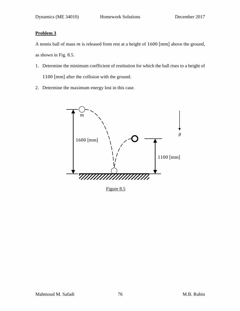
A tennis ball of mass 𝑚 is released from rest at a height of 1600 [mm] above the ground,
as shown in Fig. 8.5.
1. Determine the minimum coefficient of restitution for which the ball rises to a height of
1100 [mm] after the collision with the ground.
2. Determine the maximum energy lost in this case.
Figure 8.5
1600 [mm]
1100 [mm]
𝑚
𝑔

Dynamics (ME 34010) Homework Solutions December 2017
Mahmoud M. Safadi 77 M.B. Rubin
Solution:
Figure 8.6
Just before impact, the energy of the particle is conserved since only the gravitational force
acts on it (see Fig. 8.6). Hence,
(𝑇1 − 𝑇0) + (𝑉𝑔1 − 𝑉𝑔0) = 0 ,
where,
𝑇1 − 𝑇0 = 𝑇1 =1
2𝑚𝑣𝑚1
2 , 𝑉𝑔1 − 𝑉𝑔0 = 𝑚𝑔𝒆2 ⋅ (0 − 1600)𝒆2 = −1.6𝑚𝑔 .
Therefore, the velocity of the particle just before impact is given by
𝑣𝑚1 = √3.2𝑔 [𝑚 𝑠⁄ ] .
Next, using the coefficient of restitution 𝑒, with the subscript ‘s’ denoting the fixed
horizontal surface, it follows that
𝑒 =(𝒗𝑚2 − 𝒗𝑠2) ⋅ 𝒆2(𝒗𝑠1 − 𝒗𝑚1) ⋅ 𝒆2
= −𝑣𝑚2𝑣𝑚1
= −𝑣𝑚2
√3.2𝑔 ⇒ 𝑣𝑚2 = −𝑒√3.2𝑔 .
After impact, the energy of the particle is conserved for similar arguments as before. Hence,
(𝑇3 − 𝑇2) + (𝑉𝑔3 − 𝑉𝑔2) = 0 ,
where,
𝑇3 − 𝑇2 = −𝑇2 = −1.6𝑚𝑔𝑒2 , 𝑉𝑔3 − 𝑉𝑔2 = 𝑚𝑔𝒆2 ⋅ (1.1 − 0)𝒆2 = 1.1𝑚𝑔 .
Hence,
𝑚𝑔
𝒆2

Dynamics (ME 34010) Homework Solutions December 2017
Mahmoud M. Safadi 78 M.B. Rubin
1.6𝑚𝑔𝑒2 + 1.1𝑚𝑔 = 0 ⇒ 𝑒 = √1.1
1.6≈ 0.829 .
Furthermore, the energy lost during impact is given by
Δ𝑇 = 𝑇2 − 𝑇1 =1
2𝑚(𝑣𝑚2
2 − 𝑣𝑚12 ) =
1
2𝑚(3.2𝑔𝑒2 − 3.2𝑔) = −
1
2𝑚𝑔 .

Dynamics (ME 34010) Homework Solutions December 2017
Mahmoud M. Safadi 79 M.B. Rubin
Problem 3
Figure 8.7 shows a particle of mass 𝑚1 which is attached to the ceiling through an
inextensible string of length 𝑙1. Moreover, a particle of mass 𝑚2 is attached to 𝑚1 through
an inextensible string of length 𝑙2. At the time 𝑡 = 0, 𝑚2 is released from rest at a distance
𝑙1 below the ceiling and the string 𝑙2 is unstretched. At the instant when cos(𝛼) = 0.8 and
sin(𝛼) = 0.6, the string 𝑙2 becomes taut.
Determine the velocities of the particles just after impact, when the string 𝑙2 becomes taut.
Figure 8.7
𝑙1
𝑙2
𝛼
0.6𝑙2
𝑚1
𝑚2
𝑔

Dynamics (ME 34010) Homework Solutions December 2017
Mahmoud M. Safadi 80 M.B. Rubin
Solution:
Let 𝐴 and 𝐵 denote the particles of masses 𝑚1 and 𝑚2, respectively.
Figure 8.8
Fig. 8.8 shows that before impact, the energy of 𝐵 is conserved since only the gravitational
force acts on it. Hence,
(𝑇1 − 𝑇0) + (𝑉𝑔1 − 𝑉𝑔0) = 0 ,
where,
𝑇1 − 𝑇0 = 𝑇1 =1
2𝑚2𝑣𝐵1
2 , 𝑉𝑔2 − 𝑉𝑔1 = −𝑚2𝑔𝒆2 ⋅ 𝑙2 cos(𝛼) 𝒆2 = −𝑚2𝑔𝑙2 cos(𝛼) ,
such that the velocity of the 𝐵 just before impact is given by
𝑣𝐵1 = √2𝑔𝑙2 cos(𝛼) = √1.6𝑔𝑙2 .
Next, Fig. 8.9 shows the free body diagrams of 𝐴 and 𝐵 just after impact.
Figure 8.9
𝑚2𝑔 𝒆2
𝒆1 𝐵
𝒆2
𝒆1 𝑇1
𝐴
𝐵
𝑇2 𝛼 𝛼
𝑚1𝑔
𝑚2𝑔

Dynamics (ME 34010) Homework Solutions December 2017
Mahmoud M. Safadi 81 M.B. Rubin
Now, the velocities of the particles just after impact are given by
𝒗𝐴2 = (𝒗𝐴2 ⋅ 𝒆1)𝒆1 , 𝒗𝐵2 = (𝒗𝐵2 ⋅ 𝒆1)𝒆1 + (𝒗𝐵2 ⋅ 𝒆2)𝒆2 .
Since the gravitational forces are not impulsive (see Fig. 8.9), it follows from the balance
of linear impulse-momentum of each particle that
�̂�2 sin(𝛼) 𝒆1 + [�̂�2 cos(𝛼) − �̂�1]𝒆2 = 𝑚1(𝒗𝐴2 ⋅ 𝒆1)𝒆1 ⇒
𝒗𝐴2 ⋅ 𝒆1 =1
𝑚1�̂�2 sin(𝛼) , �̂�1 = �̂�2 cos(𝛼) ,
−�̂�2 sin(𝛼) 𝒆1 − �̂�2 cos(𝛼) 𝒆2 = 𝑚2[(𝒗𝐵2 ⋅ 𝒆1)𝒆1 + {(𝒗𝐵2 ⋅ 𝒆2) − √1.6𝑔𝑙2}𝒆2] ⇒
𝒗𝐵2 ⋅ 𝒆1 = −1
𝑚2�̂�2 sin(𝛼) , 𝒗𝐵2 ⋅ 𝒆2 = √1.6𝑔𝑙2 −
1
𝑚2�̂�2 cos(𝛼) .
Next, assuming that the strings remain taut just after impact, then
𝒗𝐵2 𝐴2⁄ ⋅ 𝒙𝐵2 𝐴2⁄ = 0 ,
such that
−(1
𝑚2+1
𝑚1) �̂�2𝑙2 sin
2(𝛼) + [√1.6𝑔𝑙2 −1
𝑚2�̂�2 cos(𝛼)] 𝑙2 cos(𝛼) = 0 ⇒
�̂�2 =𝑚1𝑚2 cos(𝛼)
𝑚1 +𝑚2 sin2(𝛼)√1.6𝑔𝑙2 .
Consequently,
�̂�1 =𝑚1𝑚2 cos
2(𝛼)
𝑚1 +𝑚2 sin2(𝛼)√1.6𝑔𝑙2 =
16𝑚1𝑚2
25𝑚1 + 9𝑚2 ,
𝒗𝐴2 ⋅ 𝒆1 = [𝑚2 cos(𝛼) sin(𝛼)
𝑚1 +𝑚2 sin2(𝛼)]√1.6𝑔𝑙2 = (
12𝑚2
25𝑚1 + 9𝑚2)√1.6𝑔𝑙2 ,
𝒗𝐵2 ⋅ 𝒆1 = −𝑚1 cos(𝛼) sin(𝛼)
𝑚1 +𝑚2 sin2(𝛼)√1.6𝑔𝑙2 = −(
12𝑚1
25𝑚1 + 9𝑚2)√1.6𝑔𝑙2 ,
𝒗𝐵2 ⋅ 𝒆2 = [𝑚1 +𝑚2
𝑚1 +𝑚2 sin2(𝛼)] sin2(𝛼)√1.6𝑔𝑙2 = 9(
𝑚1 +𝑚2
25𝑚1 + 9𝑚2)√1.6𝑔𝑙2 .

Dynamics (ME 34010) Homework Solutions December 2017
Mahmoud M. Safadi 82 M.B. Rubin
Problem Set 9 Solutions
Problem 1
Fig. 9.1 shows two particles of masses 𝑚1 = 𝑚 and 𝑚2 = 2𝑚 connected by a spring of
stiffness 𝑘 and free length 𝐿. The particles are initially at rest. At the time 𝑡 = 0, a third
particle of mass 𝑚3 = 3𝑚, traveling with speed 𝑣 in a direction perpendicular to the spring,
strikes 𝑚1. The coefficient of restitution at impact is given by 𝑒.
1. Determine the velocity of each mass just after impact.
2. Determine the angular velocity of the line connecting 𝑚1 and 𝑚2 as a function of the
distance 𝑥(𝑡) between these particles.
3. Determine the differential equation associated with 𝑥(𝑡).
Figure 9.1
𝐿
𝑚2 𝑚1
𝑚3
𝑣 𝑘

Dynamics (ME 34010) Homework Solutions December 2017
Mahmoud M. Safadi 83 M.B. Rubin
Solution:
Fig. 9.2 shows the free body diagram of the whole system at impact.
Figure 9.2
Using the definition of the coefficient of restitution, it follows that
𝑒 =(𝒗𝐵2 − 𝒗𝐷2) ⋅ 𝒆2(𝒗𝐷1 − 𝒗𝐵1) ⋅ 𝒆2
=(𝒗𝐵2 ⋅ 𝒆2) − (𝒗𝐷2 ⋅ 𝒆2)
𝑣 ⇒ (𝒗𝐵2 ⋅ 𝒆2) − (𝒗𝐷2 ⋅ 𝒆2) = 𝑒𝑣 .
Fig. 9.3 shows the free body diagrams of each particle at impact.
Figure 9.3
Since no forces act on 𝐴 during impact,
𝒗𝐴2 = 𝟎 .
Now, assuming that 𝐵 and 𝐷 are smooth, then the impulsive force �̂� has no component in
the 𝒆1 direction
�̂� ⋅ 𝒆1 = 0 ⇒ 𝑮2 ⋅ 𝒆1 = 𝑮1 ⋅ 𝒆1 .
such that
𝒗𝐷2 ⋅ 𝒆1 = 0 , 𝒗𝐵2 ⋅ 𝒆1 = 0 .
L
k 𝐵 𝐴
𝐷
𝒆1
𝒆2
2𝑚
𝑚
3𝑚
𝐵 𝐴
𝐷
�̂�
−�̂�
𝒆1
𝒆2

Dynamics (ME 34010) Homework Solutions December 2017
Mahmoud M. Safadi 84 M.B. Rubin
This shows that the velocities of 𝐵 and 𝐷 just after impact are given, respectively, by
𝒗𝐵2 = 𝑣𝐵2𝒆2 , 𝒗𝐷2 = 𝑣𝐷2𝒆2 .
Moreover, using these results, the coefficient of restitution equation reduces to
𝑣𝐵2 − 𝑣𝐷2 = 𝑒𝑣 .
Next, Fig. 9.2 also shows that the linear momentum of the system is conserved during
impact since no external forces act on it. Hence,
𝑚𝑣𝐵2 + 3𝑚𝑣𝐷2 = 3𝑚𝑣 ⇒ 𝑣𝐵2 + 3𝑣𝐷2 = 3𝑣 .
Solving the last two equations for {𝑣𝐵2, 𝑣𝐷2} yields
𝑣𝐵2 =3
4(1 + 𝑒)𝑣 , 𝑣𝐷2 =
1
4(3 − 𝑒)𝑣 .
Figure 9.4
The location of the center of mass 𝐶 of the system consisting of the particles 𝐴 and 𝐵
relative to 𝐴 is shown in Fig. 9.4 and given by
𝒙𝐶 𝐴⁄ =∑ 𝑚𝑖𝒙𝑖 𝐴⁄𝐵𝑖=𝐴
∑ 𝑚𝑖𝐵𝑖=𝐴
=2𝑚(𝟎) + 𝑚𝑥(𝑡)𝒆𝑟
3𝑚=1
3𝑥(𝑡)𝒆𝑟 .
Moreover, since no external forces act on this system, its linear momentum is conserved
so that the velocity 𝒗𝐶 of the center of mass 𝐶 is conserved as well. Hence,
𝒗𝐶 = 𝒗𝐶(𝑡2) =2𝑚𝒗𝐴2 +𝑚𝒗𝐵2
3𝑚=1
4(1 + 𝑒)𝑣𝒆2 .
𝑥(𝑡) 𝐵
𝐴 2𝑚
𝑚
𝒆𝜃
𝐶
𝑥(𝑡) 3⁄
2𝑥(𝑡) 3⁄
𝜃
𝒆𝑟

Dynamics (ME 34010) Homework Solutions December 2017
Mahmoud M. Safadi 85 M.B. Rubin
Furthermore, for the same reason, the angular momentum about the center of mass 𝐶 is
conserved. Thus,
𝑯𝐶(𝑡3) = 𝑯𝐶(𝑡2) , 𝑯𝐶(𝑡) =∑𝒙𝑖 𝐶⁄ (𝑡) ×
𝐵
𝑖=𝐴
𝑚𝑖𝒗𝑖 𝐶⁄ (𝑡) ,
where,
𝒙𝐴 𝐶⁄ = −𝑥
3𝒆𝑟 , 𝒗𝐴 𝐶⁄ = −
�̇�
3𝒆𝑟 −
𝑥�̇�
3𝒆𝜃 ,
𝒙𝐵 𝐶⁄ =2𝑥
3𝒆𝑟 , 𝒗𝐵 𝐶⁄ =
2�̇�
3𝒆𝑟 +
2𝑥�̇�
3𝒆𝜃 ,
such that,
𝑯𝐶(𝑡2) =∑𝒙𝑖 𝐶⁄ (𝑡2) ×
𝐵
𝑖=𝐴
𝑚𝑖𝒗𝑖 𝐶⁄ (𝑡2) = 𝒙𝐵 𝐶⁄ (𝑡2) × 𝑚𝒗𝐵 𝐶⁄ (𝑡2)
=2𝐿
3𝒆1 ×𝑚 [
3
4(1 + 𝑒)𝑣𝒆2] =
1
2(1 + 𝑒)𝑚𝑣𝐿𝒆3 ,
𝑯𝐶(𝑡3) =∑𝒙𝑖 𝐶⁄ (𝑡3) ×
𝐵
𝑖=𝐴
𝑚𝑖𝒗𝑖 𝐶⁄ (𝑡3)
= −𝑥
3𝒆𝑟 × 2𝑚(−
�̇�
3𝒆𝑟 −
𝑥�̇�
3𝒆𝜃) +
2𝑥
3𝒆𝑟 ×𝑚(
2�̇�
3𝒆𝑟 +
2𝑥�̇�
3𝒆𝜃)
=2𝑚𝑥2�̇�
3𝒆3 .
Equating both of these expressions yields
�̇� =3(1 + 𝑒)𝑣𝐿
4𝑥2 .
Again, for the same reason, the energy of the system is conserved, so that
𝑇3 = 𝑇2 .
Moreover, the velocities of 𝐴 and 𝐵 take the forms

Dynamics (ME 34010) Homework Solutions December 2017
Mahmoud M. Safadi 86 M.B. Rubin
𝒗𝐴 = 𝒗𝐶 + 𝒗𝐴 𝐶⁄ , 𝒗𝐵 = 𝒗𝐶 + 𝒗𝐵 𝐶⁄ ,
where,
𝑇2 =1
2𝑚𝑣𝐵2
2 =9
32(1 + 𝑒)2𝑚𝑣2 , 𝑇3 =
1
2(2𝑚)(𝒗𝐴 ⋅ 𝒗𝐴) +
1
2𝑚(𝒗𝐵 ⋅ 𝒗𝐵) .
With the help of the transformation relation
𝒆2 = sin(𝜃) 𝒆𝑟 + cos(𝜃) 𝒆𝜃 ,
it follows that
𝒗𝐴 = [1
4(1 + 𝑒)𝑣 sin(𝜃) −
�̇�
3] 𝒆𝑟 + [
1
4(1 + 𝑒)𝑣 cos(𝜃) −
𝑥�̇�
3] 𝒆𝜃 ,
𝒗𝐵 = [1
4(1 + 𝑒)𝑣 sin(𝜃) +
2�̇�
3] 𝒆𝑟 + [
1
4(1 + 𝑒)𝑣 cos(𝜃) +
2𝑥�̇�
3] 𝒆𝜃 .
Thus,
𝑇3 =3𝑚
32(1 + 𝑒)2𝑣2 sin2(𝜃) +
𝑚�̇�2
3+3𝑚
32(1 + 𝑒)2𝑣2 cos2(𝜃) +
𝑚𝑥2�̇�2
3 .
Now, equating the expressions of 𝑇2 and 𝑇3 yields
�̇�2 + 𝑥2�̇�2 =9
16(1 + 𝑒)2𝑣2 .
Substituting the expression of �̇� obtained previously into this equation gives
�̇�2 +9
16(1 + 𝑒)2𝑣2 (
𝐿2
𝑥2− 1) = 0 .
Solving this equation for 𝑥(𝑡), it follows that
𝑥
√𝑥2 − 𝐿2𝑑𝑥 =
3
4(1 + 𝑒)𝑣 𝑑𝑡 ⇒ √𝑥2 − 𝐿2 =
3
4(1 + 𝑒)𝑣𝑡 ⇒
𝑥(𝑡) = √𝐿2 + [3
4(1 + 𝑒)𝑣𝑡]
2

Dynamics (ME 34010) Homework Solutions December 2017
Mahmoud M. Safadi 87 M.B. Rubin
Problem 2
The upper end 𝐵 of the bar 𝐴𝐵, having a length of 𝐿 and mass of 𝑚, is connected to the
fixed point 𝐶 by an inextensible rope, as shown in Fig. 9.5. At the time 𝑡 = 0, the rope is
cut, with 𝜃(0) = 𝜃0 and �̇�(0) = 0.
1. Determine the angular speed �̇� of the bar as a function of 𝜃.
2. Determine the reaction forces at 𝐴.
Figure 9.5
Solution:
Fig. 9.6 shows the free body diagram of the bar just after the rope is cut.
Figure 9.6
𝑚𝑔
𝐴2
𝐴1
𝐶
𝜃
𝐴
𝐵
𝒆1
𝒆2

Dynamics (ME 34010) Homework Solutions December 2017
Mahmoud M. Safadi 88 M.B. Rubin
Since the reaction force {𝐴1, 𝐴2} at the fixed point 𝐴 don’t do work on the bar, its energy
is conserved. Therefore,
(𝑇2 − 𝑇1) + (𝑉𝑔2 − 𝑉𝑔1) = 0 ,
where,
𝑉𝑔2 − 𝑉𝑔1 = −(−𝑚𝑔𝒆2) ⋅ [𝐿
2cos(𝜃) −
𝐿
2cos(𝜃0)] 𝒆2 = −
𝑚𝑔𝐿
2[cos(𝜃0) − cos(𝜃)] ,
𝑇2 − 𝑇1 = 𝑇2 =1
2𝑚(�̅� ⋅ �̅�) +
1
2𝐼�̇̅�2 ,
�̅� = �̇�𝒆3 ×𝐿
2[sin(𝜃) 𝒆1 + cos(𝜃) 𝒆2] =
�̇�𝐿
2[− cos(𝜃) 𝒆1 + sin(𝜃) 𝒆2] ⇒
𝑇2 =1
2𝑚(
�̇�𝐿
2)
2
+1
2(𝑚𝐿2
12) �̇�2 =
𝑚𝐿2
6�̇�2 ,
such that
𝑚𝐿2
6�̇�2 −
𝑚𝑔𝐿
2[cos(𝜃0) − cos(𝜃)] = 0 ⇒
�̇�2 =3𝑔
𝐿[cos(𝜃0) − cos(𝜃)]
Also, since the bar rotates clockwise, the angular velocity is given by �̇� = −√�̇�2.
Next, the balance of linear momentum of the bar yields
𝐴1𝒆1 + (𝐴2 −𝑚𝑔)𝒆2 = 𝑚�̇̅� ,
�̇̅� =𝐿
2[{�̇�2 sin(𝜃) − �̈� cos(𝜃)}𝒆1 + {�̈� sin(𝜃) + �̇�
2 cos(𝜃)}𝒆2] .
Therefore,
𝐴1 =𝑚𝐿
2[�̇�2 sin(𝜃) − �̈� cos(𝜃)] , 𝐴2 = 𝑚 [𝑔 +
𝐿
2{�̈� sin(𝜃) + �̇�2 cos(𝜃)}] .
Furthermore, using the balance of angular momentum about the fixed point 𝐴 gives

Dynamics (ME 34010) Homework Solutions December 2017
Mahmoud M. Safadi 89 M.B. Rubin
𝑴𝐴 =𝐿
2[sin(𝜃) 𝒆1 + cos(𝜃) 𝒆2] × (−𝑚𝑔𝒆2) = −
𝑚𝑔𝐿
2sin(𝜃) 𝒆3 = �̇�𝐴 ,
where,
𝑯𝐴 = 𝑯𝐶 + 𝒙𝐶 𝐴⁄ ×𝑚�̅� =𝑚𝐿2�̇�
12𝒆3 +
𝑚𝐿2�̇�
4|
𝒆1 𝒆2 𝒆3sin(𝜃) cos(𝜃) 0− cos(𝜃) sin(𝜃) 0
| =𝑚𝐿2�̇�
3𝒆3 ⇒
�̇�𝐴 =𝑚𝐿2�̈�
3𝒆3 .
Thus,
�̈� = −3𝑔
2𝐿sin(𝜃) .
Substituting the expressions of {�̇�2, �̈�} into the expressions of the reaction forces {𝐴1, 𝐴2},
it follows that
𝐴1 =3𝑚𝑔
2sin(𝜃) [cos(𝜃0) −
1
2cos(𝜃)] ,
𝐴2 =𝑚𝑔
2[3 cos(𝜃0) cos(𝜃) +
3
2sin2(𝜃) − 1] .

Dynamics (ME 34010) Homework Solutions December 2017
Mahmoud M. Safadi 90 M.B. Rubin
Problem 3
Fig. 9.7 shows a cylinder of mass 𝑚 and radius 𝑅 which is being pulled to the right by a
constant horizontal force 𝑃 at its center 𝐶. Initially, at the time 𝑡 = 0, 𝑥(0) = 0,
�̇�(0) = −𝜔0𝑅, 𝜃(0) = 0 and �̇�(0) = 𝜔0 > 0.
Determine 𝑥(𝑡) and 𝜃(𝑡) and the magnitude of the friction force between the cylinder and
the ground for the following cases:
1. 𝑃 = 0.
2. 𝑃 = 2𝜇𝑚𝑔.
3. 𝑃 = 4𝜇𝑚𝑔.
Figure 9.7
𝑔
𝒆1
𝒆2
𝐶
𝑃
�̇�, �̈�
𝑅
𝑥

Dynamics (ME 34010) Homework Solutions December 2017
Mahmoud M. Safadi 91 M.B. Rubin
Solution:
The free body diagram of the cylinder is shown in Fig. 9.8.
Figure 9.8
Assuming that the cylinder rolls without slipping along the ground, then
𝒗𝐶 𝐵⁄ = 𝒗𝐶 = �̇�𝒆1 = 𝝎× 𝒙𝐶 𝐵⁄ = 𝜔𝒆3 × 𝑅𝒆2 = −𝜔𝑅𝒆1 ⇒ �̇� = −𝜔𝑅 , �̈� = −�̇�𝑅 .
Moreover, the balance equations of linear momentum and angular momentum about the
center 𝐶 yield
𝑁 = 𝑚𝑔 , 𝑃 − 𝑓 = 𝑚�̈� ,
−𝑅𝑓 = 𝐼𝐶�̇� =1
2𝑚𝑅2�̇� ⇒ 𝑓 = −
1
2𝑚𝑅�̇� =
1
2𝑚�̈� .
Therefore,
𝑓 =1
3𝑃 , �̈� =
2
3
𝑃
𝑚 , �̇� = −
2
3
𝑃
𝑚𝑅 .
Now, in rolling without slipping, the friction force is static. Thus,
|𝑓| ≤ 𝜇|𝑁| ⇒ 𝑃 ≤ 3𝜇𝑚𝑔 .
Case 1: 𝑃 = 0
Since 𝑃 < 3𝜇𝑚𝑔, the cylinder rolls without slipping along the ground. Thus,
�̈� = 0 ⇒ 𝑥(𝑡) = 𝑥(0) + �̇�(0)𝑡 = −𝜔0𝑅𝑡 ,
𝐵
𝐶
𝑚𝑔
𝑓
𝑁
𝑅 𝒆1
𝒆2
𝑃

Dynamics (ME 34010) Homework Solutions December 2017
Mahmoud M. Safadi 92 M.B. Rubin
�̇� = 0 ⇒ 𝜃(𝑡) = 𝜃(0) + �̇�(0)𝑡 = 𝜔0𝑡 .
Case 2: 𝑃 = 2𝜇𝑚𝑔
Since 𝑃 < 3𝜇𝑚𝑔, the cylinder rolls without slipping along the ground. Thus,
�̈� =2
3
𝑃
𝑚=4𝜇𝑔
3 ⇒ 𝑥(𝑡) = 𝑥(0) + �̇�(0)𝑡 +
1
2(4𝜇𝑔
3) 𝑡2 = (
2𝜇𝑔𝑡
3− 𝜔0𝑅) 𝑡 ,
�̇� = −2
3
𝑃
𝑚𝑅= −
4𝜇𝑔
3𝑅 ⇒ 𝜃(𝑡) = 𝜃(0) + �̇�(0)𝑡 +
1
2(−
4𝜇𝑔
3𝑅) 𝑡2 = (𝜔0 −
2𝜇𝑔
3𝑅) 𝑡 .
Case 3: 𝑃 = 4𝜇𝑚𝑔
Since 𝑃 > 3𝜇𝑚𝑔, the cylinder slips on the ground. Thus,
𝑓 = 𝜇𝑁 = 𝜇𝑚𝑔 .
Furthermore, the equations of motion are given by
𝑃 − 𝜇𝑚𝑔 = 𝑚�̈� ⇒ �̈� = 3𝜇𝑔 , − 𝑅𝜇𝑚𝑔 =1
2𝑚𝑅2�̇� ⇒ �̇� = −
2𝜇𝑔
𝑅 .
Thus,
𝑥(𝑡) = 𝑥(0) + �̇�(0)𝑡 +1
2(3𝜇𝑔)𝑡2 = (
3𝜇𝑔𝑡
2− 𝜔0𝑅) 𝑡 ,
𝜃(𝑡) = 𝜃(0) + �̇�(0)𝑡 +1
2(−
2𝜇𝑔
𝑅) 𝑡2 = (𝜔0 −
𝜇𝑔𝑡
𝑅) 𝑡 .

Dynamics (ME 34010) Homework Solutions December 2017
Mahmoud M. Safadi 93 M.B. Rubin
Problem 4
A bowling ball of mass 𝑚 and radius 𝑅 is thrown onto the ground with a velocity 𝑣0 that
is essentially horizontal. The friction coefficient between the ball and the ground is 𝜇.
Initially, at the time 𝑡 = 0, 𝜃(0) = 0 and �̇�(0) = 0.
Determine the distance traveled by the ball before it starts rolling without slipping on the
ground.
Solution:
The free body diagram of the ball is shown in Fig. 9.9.
Figure 9.9
Since the ball slips on the ground, the friction force 𝑓 acting on it at the contact point 𝐵
with the ground is given by
𝑓 = 𝜇𝑁 .
Now, using the balance of linear momentum and angular momentum about the center 𝐶 of
the ball, it follows that
𝑁 = 𝑚𝑔 , − 𝑓 = −𝜇𝑚𝑔 = 𝑚�̇� ⇒ �̇� = −𝜇𝑔 ⇒ 𝑣 = 𝑣(0) − 𝜇𝑔𝑡 = 𝑣0 − 𝜇𝑔𝑡 ;
−𝑅𝑓 = −𝜇𝑚𝑔𝑅 = 𝐼�̈̅� =2
5𝑚𝑅2�̇� ⇒ �̈� = −
5𝜇𝑔
2𝑅 ⇒ �̇� = �̇�(0) −
5𝜇𝑔𝑡
2𝑅= −
5𝜇𝑔𝑡
2𝑅 .
𝐵
𝐶
𝑚𝑔
𝑓
𝑁
𝑣
𝜔
𝑅 𝒆1
𝒆2

Dynamics (ME 34010) Homework Solutions December 2017
Mahmoud M. Safadi 94 M.B. Rubin
Next, when the ball starts rolling without slipping, the velocity of the contact point 𝐵 with
the ground vanishes, 𝒗𝐵 = 0. Thus, the time spent up to this point is calculated using the
kinematic condition for rolling without slipping, namely
𝒗𝐶 = 𝒗𝐶 𝐵⁄ = 𝝎× 𝒙𝐶 𝐵⁄ = −𝑅𝜔𝒆1 ⇒ 𝑣0 − 𝜇𝑔𝑡 = −𝑅 (−5𝜇𝑔𝑡
2𝑅) 𝑡 ⇒ 𝑡 =
2𝑣07𝜇𝑔
.
Moreover, the distance traveled up to this point is given by
𝑥 = 𝑥(0) + 𝑣0𝑡 −1
2𝜇𝑔𝑡2 = 𝑣0 (
2𝑣07𝜇𝑔
) −1
2𝜇𝑔 (
2𝑣07𝜇𝑔
)2
=12𝑣0
2
49𝜇𝑔 .

Dynamics (ME 34010) Homework Solutions December 2017
Mahmoud M. Safadi 95 M.B. Rubin
Problem Set 10 Solutions
Problem 1
Consider the assembly shown in Fig. 10.1. The hanging block of mass 𝑚1 is attached to
the cylinder of center 𝐵, mass 𝑚2 and radius 𝑟2 by an inextensible cord, wrapped at a radius
𝑟1 and passes over a drum of center 𝐴, mass 𝑚3 and radius 𝑅.
It is assumed that the cord does not slip on the drum and the cylinder. Moreover, the
coefficient of friction between the cylinder and the ground is 𝜇.
1. Assuming that the cylinder rolls without slipping along the ground, determine the
acceleration of the block.
2. Assuming that
{𝜇 = 0.3,𝑚1 = 𝑚,𝑚2 = 𝑚 2⁄ , 𝑟1 = 𝑟, 𝑟2 = 2𝑟, 𝐼2̅ = 6𝑚𝑟2, 𝐼3̅ = 3𝑚𝑟2, 𝑅 = 𝑟1 + 𝑟2},
show that the cylinder slips along the ground. Also, determine the acceleration of the
block.
Figure 10.1
𝑅
𝑚3 𝑚2 𝑟1 𝑟2
𝑚1
𝐴
𝐵
𝜇
𝑔

Dynamics (ME 34010) Homework Solutions December 2017
Mahmoud M. Safadi 96 M.B. Rubin
Solution:
The free body diagrams of each part is shown in Fig. 10.2.
Figure 10.2
The balance of linear momentum equations of the block and cylinder are given by
𝑇𝐴 −𝑚1𝑔 = −𝑚1�̈� ; 𝑁 = 𝑚2𝑔 , 𝑓 − 𝑇𝐵 = 𝑚2�̈� .
Moreover, the balance of angular momentum equations of the drum and cylinder about
their center of mass yield
(𝑇𝐴 − 𝑇𝐵)𝑅 = 𝐼𝐴�̇�𝐴 , 𝑓𝑟2 + 𝑇𝐵𝑟1 = 𝐼𝐵�̇�𝐵 .
Next, since the cylinder rolls without slipping on the ground
𝒗𝐷 = �̇�𝒆1 + 𝜔𝐵𝒆3 × (−𝑟2𝒆2) = (�̇� + 𝜔𝐵𝑟2)𝒆1 = 𝟎 ⇒ �̈� = −�̇�𝐵𝑟2 .
Now, since the cord does not slip on the drum and the cylinder
𝒗𝐶′ = 𝒗𝐶 = 𝜔𝐴𝒆3 × (−𝑅𝒆1) = −𝜔𝐴𝑅𝒆2 , 𝒗𝐹′ = 𝒗𝐹 = 𝜔𝐴𝒆3 × 𝑅𝒆2 = −𝜔𝐴𝑅𝒆1 ,
𝒗𝐸′ = 𝒗𝐸 = �̇�𝒆1 + 𝜔𝐵𝒆3 × 𝑟1𝒆2 = (�̇� − 𝜔𝐵𝑟1)𝒆1 .
Also, the inextensibility of the cord yields

Dynamics (ME 34010) Homework Solutions December 2017
Mahmoud M. Safadi 97 M.B. Rubin
𝒗𝐶′ = −�̇�𝒆2 , 𝒗𝐹′ = 𝒗𝐸′ .
Thus,
�̈� = �̇�𝐴𝑅 , �̈� = �̇�𝐵𝑟1 − �̇�𝐴𝑅 .
In summary, the equations of motion to be solved are given by
𝑇𝐴 −𝑚1𝑔 = −𝑚1�̈� , 𝑓 − 𝑇𝐵 = 𝑚2�̈� , (𝑇𝐴 − 𝑇𝐵)𝑅 = 𝐼𝐴�̇�𝐴 , 𝑓𝑟2 + 𝑇𝐵𝑟1 = 𝐼𝐵�̇�𝐵 ,
�̈� = −�̇�𝐵𝑟2 , �̈� = �̇�𝐴𝑅 , �̈� = �̇�𝐵𝑟1 − �̇�𝐴𝑅 .
Consequently,
�̈� = [𝑚1𝑅
2(𝑟1 + 𝑟2)2
{𝐼𝐴 + (𝑚1 +𝑚2)𝑅2}𝑟22 + 2(𝐼𝐴 +𝑚1𝑅2)𝑟1𝑟2 + (𝐼𝐵 +𝑚1𝑟1
2)𝑅2 + 𝐼𝐴𝑟12] 𝑔 .
Next, since the cylinder rolls without slipping on the ground, the frictional force satisfies
|𝑓| ≤ |𝜇𝑁| .
where 𝑁 = 𝑚2𝑔 and 𝑓 is obtained by solving the equations of motion, such that
𝑓 = [(𝐼𝐵 −𝑚2𝑟1𝑟2)𝑅
2
{𝐼𝐴 + (𝑚1 +𝑚2)𝑅2}𝑟22 + 2(𝐼𝐴 +𝑚1𝑅2)𝑟1𝑟2 + (𝐼𝐵 +𝑚1𝑟1
2)𝑅2 + 𝐼𝐴𝑟12]𝑚1𝑔 .
Therefore,
𝜇 ≥ [(𝐼𝐵 −𝑚2𝑟1𝑟2)𝑅
2
{𝐼𝐴 + (𝑚1 +𝑚2)𝑅2}𝑟22 + 2(𝐼𝐴 +𝑚1𝑅2)𝑟1𝑟2 + (𝐼𝐵 +𝑚1𝑟1
2)𝑅2 + 𝐼𝐴𝑟12]𝑚1
𝑚2 .
Substituting the given data into this inequality yields
𝜇 ≥1
2 ,
which shows that if 𝜇 = 1 3⁄ , the cylinder slips along the ground. Also, in this case, the
frictional force is given by 𝑓 = 𝜇𝑁 = 𝑚2𝑔 3⁄ and the equations of motion reduce to
𝑇𝐴 −𝑚1𝑔 = −𝑚1�̈� , 1
3𝑚2𝑔 − 𝑇𝐵 = 𝑚2�̈� , (𝑇𝐴 − 𝑇𝐵)𝑅 = 𝐼𝐴�̇�𝐴 ,
1
3𝑚2𝑔𝑟2 + 𝑇𝐵𝑟1 = 𝐼𝐵�̇�𝐵 , �̈� = �̇�𝐴𝑅 , �̈� = �̇�𝐵𝑟1 − �̇�𝐴𝑅 .

Dynamics (ME 34010) Homework Solutions December 2017
Mahmoud M. Safadi 98 M.B. Rubin
Solving this system of equations for �̈�, it follows that
�̈� = [{3𝑚1𝑚2𝑟1
2 +𝑚22𝑟1𝑟2 + (3𝑚1 −𝑚2)𝐼𝐵}𝑅
2
{𝐼𝐴 + (𝑚1 +𝑚2)𝑅2}𝐼𝐵 +𝑚2𝑟12(𝐼𝐴 +𝑚1𝑅2)
]𝑔
3 .
Substituting the given data into this expression gives
�̈� =17
35𝑔 ≈ 0.486𝑔 .

Dynamics (ME 34010) Homework Solutions December 2017
Mahmoud M. Safadi 99 M.B. Rubin
𝑅
𝐶
𝑚1
𝑚2 𝑚3 𝑣
𝜇
𝑔
Problem 2
Figure 10.3 shows a cylinder of center 𝐶, mass 𝑚1 and radius 𝑅 which is placed on a
stationary box of mass 𝑚2. The coefficient of friction between the cylinder and the box is
𝜇. At the time 𝑡 = 0, a block of mass 𝑚1, moving freely with a leftward velocity of 𝑣,
strikes the box and sticks to it.
1. Assuming that 𝜇 = 0, determine the velocities of the box and the center 𝐶 of the
cylinder just after impact.
2. Assuming that 𝜇 > 0 and the cylinder slips on the box during impact, determine the
velocities of the box and the center 𝐶 of the cylinder just after impact.
3. Using your answers in part 2, determine the time it takes for the cylinder to begin rolling
without slipping on the box.
4. Assuming that 𝜇 → ∞, determine the velocities of the box and the center 𝐶 of the
cylinder just after impact.
Figure 10.3

Dynamics (ME 34010) Homework Solutions December 2017
Mahmoud M. Safadi 100 M.B. Rubin
Solution:
The free body diagrams of the cylinder and the system consisting of the box and the block
at impact are shown in Fig. 10.4.
Figure 10.4
Since the block sticks to the box, their velocities {𝒗𝐴2, 𝒗𝐵2} just after impact are equal
𝒗𝐴2 = 𝒗𝐵2 = 𝑢𝒆1 .
Next, for a finite value of 𝜇, the impulsive force �̂� = ∫ 𝑭𝑑𝑡𝑡2
𝑡1 at impact (𝑡2 → 𝑡1) vanishes.
Thus, the balance equations of linear impulse-momentum and angular-impulse momentum
about the center of mass 𝐶 of the cylinder give
�̂� = 𝑚1(𝒗𝐶2 − 𝒗𝐶1) = 𝟎 ⇒ 𝒗𝐶2 = 𝒗𝐶1 = 𝟎 ,
�̂�𝐶 = 𝐼𝐶(𝜔2 − 𝜔1)𝒆3 = 𝟎 ⇒ 𝜔2 = 𝜔1 = 0 .
Moreover, the balance of linear impulse-momentum equation of the system consisting of
the box and the block yields
−�̂� = 𝑚2(𝒗𝐵2 − 𝒗𝐵1) + 𝑚3(𝒗𝐴2 − 𝒗𝐴1) = 𝟎 ⇒

Dynamics (ME 34010) Homework Solutions December 2017
Mahmoud M. Safadi 101 M.B. Rubin
𝑚2𝑢𝒆1 +𝑚3[𝑢𝒆1 − (−𝑣𝒆1)] = 𝟎 ⇒ 𝑢 = −(𝑚3
𝑚2 +𝑚3) 𝑣 ,
such that
𝒗𝐴2 = 𝒗𝐵2 = −(𝑚3
𝑚2 +𝑚3) 𝑣𝒆1 .
Now, if the cylinder slips along the box, then
𝑭 = −sgn(𝒗𝑠𝑙𝑖𝑝)𝑓𝒆1 + 𝑁𝒆2 , 𝑓 = 𝜇𝑁 ,
sgn(𝒗𝑠𝑙𝑖𝑝) = sgn(𝒗𝐷 𝐷′⁄ ) = sgn(−𝒗𝐷′) = sgn(−𝒗𝐵) = +1 .
Therefore, the balance of linear momentum of the cylinder yields
𝑁 = 𝑚1𝑔 , − 𝜇𝑚1𝑔 = 𝑚1�̈� ⇒ �̈� = −𝜇𝑔 , �̇�(0) = 0 ⇒ �̇� = −𝜇𝑔𝑡 .
Furthermore, using the balance of angular momentum of the cylinder about its center of
mass 𝐶, it follows that
−𝜇𝑚1𝑔𝑅 = 𝐼𝐶�̇� , 𝜔(0) = 0 ⇒ 𝜔 = −𝜇𝑚1𝑔𝑅
𝐼𝐶𝑡 = −
𝜇𝑚1𝑔𝑅
12𝑚1𝑅
2𝑡 = −
2𝜇𝑔
𝑅𝑡 .
Next, at the instant when the cylinder starts rolling without slipping on the box, then
𝒗𝐶 = −𝜇𝑔𝑡𝒆1 = 𝒗𝐷 +𝝎× 𝒙𝐶 𝐷⁄ = 𝒗𝐷′ −
2𝜇𝑔
𝑅𝑡𝒆3 × 𝑅𝒆2 ⇒ 𝒗𝐷
′ = −3𝜇𝑔𝑡𝒆1 .
where the velocity 𝒗𝐷′ of the box is calculated using the balance of linear momentum, such
that
−𝑭 + (𝑁2 −𝑚2𝑔)𝒆2 = 𝜇𝑚1𝑔𝒆1 + (𝑁2 −𝑚1𝑔 −𝑚2𝑔)𝒆2 = 𝑚2�̈�𝒆1 ⇒
𝑁2 = (𝑚1 +𝑚2)𝑔 , �̈� =𝜇𝑚1𝑔
𝑚2 , �̇�(0) = 𝑢 = −(
𝑚3
𝑚2 +𝑚3) 𝑣 ⇒
�̇� = −(𝑚3
𝑚2 +𝑚3) 𝑣 +
𝜇𝑚1𝑔
𝑚2𝑡 ⇒ 𝒗𝐷
′ = [−(𝑚3
𝑚2 +𝑚3) 𝑣 +
𝜇𝑚1𝑔
𝑚2𝑡] 𝒆1 .
Hence, the time it takes for the cylinder to begin rolling without slipping is given by

Dynamics (ME 34010) Homework Solutions December 2017
Mahmoud M. Safadi 102 M.B. Rubin
−(𝑚3
𝑚2 +𝑚3) 𝑣 +
𝜇𝑚1𝑔
𝑚2𝑡 = −3𝜇𝑔𝑡 ⇒ 𝑡 = [
𝑚2𝑚3
(𝑚2 +𝑚3)(3𝑚2 +𝑚1)]𝑣
𝜇𝑔 .
On the other hand, if 𝜇 → ∞, then the cylinder rolls without slipping along the box and the
frictional force satisfies |𝑓| ≤ 𝜇|𝑁|. Therefore, the balance equations of linear impulse-
momentum and angular-impulse momentum about the center of mass 𝐶 of the cylinder
give
�̂� = 𝑓𝒆1 + �̂�𝒆2 = 𝑚1(𝑣𝐶2 − 𝑣𝐶1)𝒆1 = 𝑚1𝑣𝐶2𝒆1 ⇒ �̂� = 0 , 𝑓 = 𝑚1𝑣𝐶2 ,
𝑅𝑓 =1
2𝑚1𝑅
2(𝜔 − 𝜔0) =1
2𝑚1𝑅
2𝜔 ⇒ 𝑓 =1
2𝑚1𝑅𝜔 .
Moreover, the balance of linear impulse-momentum equation of the system consisting the
box and the block yields
−�̂� = 𝑚2(𝒗𝐵2 − 𝒗𝐵1) + 𝑚3(𝒗𝐴2 − 𝒗𝐴1) = [(𝑚2 +𝑚3)𝑢 + 𝑚3𝑣]𝒆1 ⇒
−𝑓 = (𝑚2 +𝑚3)𝑢 + 𝑚3𝑣 .
Also, since the cylinder rolls without slipping along the box
𝒗𝐷2 = 𝒗𝐷′2 ⇒ 𝒗𝐶2 +𝝎× 𝒙𝐷 𝐶⁄ = (𝑣𝐶2 + 𝜔𝑅)𝒆1 = 𝑢𝒆1 ⇒ 𝑢 = 𝑣𝐶2 + 𝜔𝑅 .
Next, solving the system of equations
𝑓 = 𝑚1𝑣𝐶2 , 𝑓 =1
2𝑚1𝑅𝜔 , − 𝑓 = (𝑚2 +𝑚3)𝑢 + 𝑚3𝑣 , 𝑢 = 𝑣𝐶2 + 𝜔𝑅 ,
for {𝑣𝐶2, 𝑢, 𝜔, 𝑓} it follows that
𝑣𝐶2 = −[𝑚3
𝑚1 + 3(𝑚2 +𝑚3)] 𝑣 , 𝑢 = − [
3𝑚3
𝑚1 + 3(𝑚2 +𝑚3)] 𝑣 ,
𝜔 = −[2𝑚3
𝑚1 + 3(𝑚2 +𝑚3)]𝑣
𝑅 , 𝑓 = − [
𝑚3
𝑚1 + 3(𝑚2 +𝑚3)]𝑚1𝑣 .

Dynamics (ME 34010) Homework Solutions December 2017
Mahmoud M. Safadi 103 M.B. Rubin
Problem 3
Figure 10.5 shows a disk of mass 𝑚 and radius 𝑏, which is attached to a frame by an
inextensible cord of length 3𝑏 passing through its center 𝐶. The frame rotates with a
constant angular acceleration �̈� = 𝑝. The coefficient of friction between the disk and the
frame at the point of contact 𝐵 is 𝜇. Initially, at the time 𝑡 = 0, 𝜃(0) = 0 and both the disk
and the frame are at rest. The maximum tension in the cord is given by 𝑇𝑐𝑟. Also, gravity
is neglected.
Figure 10.5
1. Assuming that 𝜇 = 0, determine:
1.1. the angular velocity of the disk.
1.2. the tension in the cord.
1.3. the angular velocity of the frame when the disk is on the verge of bouncing off.
2. Determine the critical value of 𝜇, denoted by 𝜇𝑐𝑟, for which the disk slips on the frame
at the onset of motion.
3. If 𝜇 > 𝜇𝑐𝑟, determine the angular velocity of the frame when the disk is on the verge
of slipping.
𝑂
𝐴
𝐶
𝑏 3𝑏
𝜃
𝑚
𝜇
𝐵

Dynamics (ME 34010) Homework Solutions December 2017
Mahmoud M. Safadi 104 M.B. Rubin
4. Assuming that the disk does not slip on the frame, determine:
4.1. the kinetic energy of the disk.
4.2. the angular momentum of the disk about the fixed point 𝑂.
4.3. the minimum value of the angular acceleration of the disk for which the cord tears at
the onset of motion.
Solution:
The free body diagram of the disk is shown in Fig. 10.6.
Figure 10.6
In the absence of friction (𝑓 = 0), the balance of linear momentum and angular momentum
about the center of mass of the disk yield
𝑴𝐶 = 𝟎 = 𝐼𝐶�̇�𝒆3 ⇒ 𝜔 = 𝜔(0) = 0 , − 𝑇𝒆𝑟 + 𝑁𝒆𝜃 = 𝑚�̅� ,
�̅� = 𝒗𝐶 𝐴⁄ =𝑑(3𝑏𝒆𝑟 + 𝑏𝒆𝜃)
𝑑𝑡= 𝑏(−�̇�𝒆𝑟 + 3�̇�𝒆𝜃) ⇒
�̅� = �̇̅� = 𝑏[−(3�̇�2 − �̈�)𝒆𝑟 + (3�̈� − �̇�2)𝒆𝜃] ,
Thus,
𝑇 = 𝑚𝑏(3�̇�2 − �̈�) , 𝑁 = 𝑚𝑏(3�̈� − �̇�2) .
Now, using
�̈� = 𝑝 , �̇�(0) = 0 ⇒ �̇� = 𝑝𝑡 ,

Dynamics (ME 34010) Homework Solutions December 2017
Mahmoud M. Safadi 105 M.B. Rubin
it follows that
𝑇 = 𝑚𝑏(3𝑝2𝑡2 − 𝑝) , 𝑁 = 𝑚𝑏(3𝑝 − 𝑝2𝑡2).
Also, the angular velocity of the frame when the disk is on the verge of bouncing off is
given by
𝑁(�̇�𝑐) = 0 ⇒ 𝑚𝑏(3𝑝 − �̇�𝑐2) = 0 ⇒ �̇�𝑐 = √3𝑝 .
Next, assuming that the disk rolls without slipping along the frame at the onset of motion,
then the equations of motion become
𝑓 − 𝑇 = 𝑚𝑏(3�̇�2 − �̈�) , 𝑁 = 𝑚𝑏(3�̈� − �̇�2) , 𝑏𝑓 =1
2𝑚𝑏2�̇� .
Moreover, this no-slip condition yields
𝒗𝐵 = 𝒗𝐵′ = 3𝑏�̇�𝒆𝜃 ,
such that
�̅� = 𝑏(−�̇�𝒆𝑟 + 3�̇�𝒆𝜃)
= 𝒗𝐵 +𝝎× 𝒙𝐶 𝐵⁄ = 3𝑏�̇�𝒆𝜃 + 𝜔𝒆3 × 𝑏𝒆𝜃 = 𝑏(−𝜔𝒆𝑟 + 3�̇�𝒆𝜃)
which gives
𝜔 = �̇� ⇒ �̇� = �̈� = 𝑝 .
Therefore, the static frictional force takes the form
𝑓 =1
2𝑚𝑏�̇� =
1
2𝑚𝑏𝑝 ,
and it must satisfy
|𝑓| ≤ 𝜇|𝑁| ⇒ 𝜇 ≥ 𝜇𝑐𝑟 , 𝜇𝑐𝑟 =|𝑓|
|𝑁| .
Now, at the onset of motion
𝑁(0) = 3𝑚𝑏𝑝 .

Dynamics (ME 34010) Homework Solutions December 2017
Mahmoud M. Safadi 106 M.B. Rubin
Thus,
𝜇𝑐𝑟 =
12𝑚𝑏𝑝
3𝑚𝑏𝑝=1
6 .
Also, when the disk is on the verge of slipping, it follows that
|𝑓| = 𝜇|𝑁| ⇒ �̇� = √(3 −1
2𝜇) 𝑝 .
Next, if the disk does not slip along the frame for all times, then its kinetic becomes
𝑇 =1
2𝑚(�̅� ⋅ �̅�) +
1
2(1
2𝑚𝑏2)𝜔2 ,
where (see the previous results),
�̅� = 𝑏(−𝜔𝒆𝑟 + 3�̇�𝒆𝜃) = 𝑏�̇�(−𝒆𝑟 + 3𝒆𝜃) = 𝑏𝑝𝑡(−𝒆𝑟 + 3𝒆𝜃) ,
such that
𝑇 =1
2𝑚(10𝑏2𝑝2𝑡2) +
1
4𝑚𝑏2𝑝2𝑡2 =
21
4𝑚𝑏2𝑝2𝑡2 .
Moreover, the angular momentum of the disk about the fixed point O is given by
𝑯𝑂 = �̅� + 𝒙𝐶 𝑂⁄ ×𝑚�̅� =1
2𝑚𝑏2𝑝𝑡𝒆3 + |
𝒆𝑟 𝒆𝜃 𝒆33𝑏 𝑏 0
−𝑚𝑏𝑝𝑡 3𝑚𝑏𝑝𝑡 0| =
21
4𝑚𝑏2𝑝𝑡𝒆3 .
Now, recall that the equations of motion in this case (no-slip) take the forms
𝑓 − 𝑇 = 𝑚𝑏(3�̇�2 − 𝑝) , 𝑁 = 𝑚𝑏(3𝑝 − �̇�2) , 𝑏𝑓 =1
2𝑚𝑏2�̇� =
1
2𝑚𝑏2𝑝 .
Hence, if the cord tears at the onset of motion, then 𝑇 = 𝑇𝑐𝑟 and �̇� = 0 so that
𝑓 − 𝑇𝑐𝑟 = −𝑚𝑏𝑝𝑐𝑟 , 𝑏𝑓 =1
2𝑚𝑏2𝑝𝑐𝑟 .
Solving these two equations for {𝑝𝑐𝑟, 𝑓} yields
𝑝𝑐𝑟 =2
3
𝑇𝑐𝑟𝑚𝑏
, 𝑓 =1
3𝑇𝑐𝑟 .

Dynamics (ME 34010) Homework Solutions December 2017
Mahmoud M. Safadi 107 M.B. Rubin
𝑅
𝐶
𝑚1
𝑚2
𝐿 = 4𝑅
𝜇
Problem 4
Consider the assembly shown in Fig. 10.7. The hanging block of mass 𝑚2 is attached to
the cylinder of center 𝐶, mass 𝑚1 and radius 𝑅 by an inextensible cord, wrapped around
the cylinder and passes over a massless pulley. The coefficient of friction between the
cylinder and the ground is 𝜇. Moreover, the system is released from rest with the cylinder
being at a distance 4𝑅 relative to the fixed vertical wall. The coefficient of restitution
between the vertical wall and the cylinder is given by 𝑒 = 1 2⁄ .
1. Assuming that the cylinder rolls without slipping along the ground, determine:
1.1. the acceleration of its center 𝐶 at the onset of motion.
1.2. the minimum value of 𝜇 for this to happen.
1.3. the velocity of its center 𝐶 just before impact with the wall.
2. Determine the velocity of the center 𝐶 of the cylinder just after impact with the wall.
3. Determine the angular velocity of the cylinder just after impact with the wall.
4. Does the cylinder slip along the ground just after impact with the wall? Explain your
answer.
Figure 10.7

Dynamics (ME 34010) Homework Solutions December 2017
Mahmoud M. Safadi 108 M.B. Rubin
Solution:
The free body diagrams of the cylinder and the block before impact are shown in Fig. 10.8.
Figure 10.8
If the cylinder rolls without slipping on the ground, then
𝒗𝐵 = 𝟎 ⇒ 𝒗𝐶 = �̇�𝒆1 = 𝒗𝐵 +𝝎× 𝒙𝐶 𝐵⁄ = 𝜔𝒆3 × 𝑅𝒆2 = −𝜔𝑅𝒆1 ⇒ �̈� = −�̇�𝑅 .
Furthermore, assuming that the cord does not slip along the cylinder, it follows that
𝒗𝐷 𝐷′⁄ = 𝟎 ,
where,
𝒗𝐷 = 𝒗𝐶 +𝝎× 𝒙𝐶 𝐵⁄ = �̈�𝒆1 + 𝜔𝒆3 × 𝑅𝒆2 = (�̈� − 𝜔𝑅)𝒆1 , 𝒗𝐷′ = �̇�𝒆1 ,
such that
�̈� − �̇�𝑅 = �̈� .
Next, using that balance equation of linear momentum of the block and the cylinder
together with the balance equation of angular momentum about the center of mass 𝐶 of the
cylinder, it follows that
𝑇 −𝑚2𝑔 = −𝑚2�̈� , 𝑇 − 𝑓 = 𝑚1�̈� , 𝑁 = 𝑚1𝑔 , − 𝑅𝑓 =1
2𝑚𝑅2�̇� .

Dynamics (ME 34010) Homework Solutions December 2017
Mahmoud M. Safadi 109 M.B. Rubin
Solving the system of equations
�̈� = −�̇�𝑅 , �̈� − �̇�𝑅 = �̈� ,
𝑇 −𝑚2𝑔 = −𝑚2�̈� , 𝑇 − 𝑓 = 𝑚1�̈� , 𝑁 = 𝑚1𝑔 , − 𝑅𝑓 =1
2𝑚𝑅2�̇� ,
for {�̈�, �̈�, �̇�, 𝑇, 𝑓} yield
�̈� = (2𝑚2
3𝑚1 + 4𝑚2)𝑔 , �̈� = (
4𝑚2
3𝑚1 + 4𝑚2) 𝑔 , �̇� = −(
2𝑚2
3𝑚1 + 4𝑚2)𝑔
𝑅 ,
𝑇 =3𝑚1𝑚2𝑔
3𝑚1 + 4𝑚2 , 𝑓 =
𝑚1𝑚2𝑔
3𝑚1 + 4𝑚2 .
Furthermore, since the frictional force is static in this case
𝑓 ≤ 𝜇𝑁 ⇒ 𝜇 ≥𝑚2
3𝑚1 + 4𝑚2 .
Now, the velocity �̇� of the center of mas 𝐶 of the cylinder is given by
�̇� = �̇�(0) + (2𝑚2
3𝑚1 + 4𝑚2) 𝑔𝑡 , �̇�(0) = 0 ⇒ �̇� = (
2𝑚2
3𝑚1 + 4𝑚2) 𝑔𝑡 .
However,
Δ𝑥 = 4𝑅 = �̇�(0)𝑡 +1
2(
2𝑚2
3𝑚1 + 4𝑚2) 𝑔𝑡2 ⇒ 𝑡 = 2√
(3𝑚1 + 4𝑚2)𝑅
𝑚2𝑔 .
Hence,
�̇� = 4√𝑚2𝑔𝑅
3𝑚1 + 4𝑚2 .
Also, the angular velocity 𝜔 of the cylinder becomes
�̇� = −�̇�
𝑅 ⇒ 𝜔 = −4√(
𝑚2
3𝑚1 + 4𝑚2)𝑔
𝑅 .
Next, the free body diagram of the cylinder at impact is shown in Fig. 10.9.

Dynamics (ME 34010) Homework Solutions December 2017
Mahmoud M. Safadi 110 M.B. Rubin
Figure 10.9
Using the definition of the coefficient of restitution, it follows that
𝑒 = −𝒗𝐸2 ⋅ 𝒆1𝒗𝐸1 ⋅ 𝒆1
, 𝒗𝐸(𝑡) = 𝒗𝐶 +𝝎× 𝒙𝐸 𝐶⁄ = �̇�(𝑡)𝒆1 ⇒ �̇�(𝑡2) = −𝑒�̇�(𝑡1) ⇒
�̇�(𝑡2) = −4𝑒√𝑚2𝑔𝑅
3𝑚1 + 4𝑚2 .
Moreover, using the balance equations of impulse-linear momentum and impulse-angular
momentum about the center of mass of the cylinder at impact yield
�̂� = �̂�1𝒆1 + �̂�2𝒆2 = 𝑚1[�̇�(𝑡2) − �̇�(𝑡1)]𝒆1 ⇒ �̂�2 = 0 ,
�̂�1 = −4(𝑒 + 1)𝑚1√𝑚2𝑔𝑅
3𝑚1 + 4𝑚2 ,
−𝑅�̂�2 = 0 =1
2𝑚1𝑅
2[𝜔(𝑡2) − 𝜔(𝑡1)] ⇒ 𝜔(𝑡2) = 𝜔(𝑡1) = −4√(𝑚2
3𝑚1 + 4𝑚2)𝑔
𝑅 .
This shows that the cylinder slips along the ground just after impact since
|�̇�(𝑡2)| ≠ 𝜔(𝑡2)𝑅 .

Dynamics (ME 34010) Homework Solutions December 2017
Mahmoud M. Safadi 111 M.B. Rubin
Problem Set 11 Solutions
Problem 1
A uniform circular disk of mass 𝑚 = 23 [kg] and radius 𝑅 = 0.4 [m] rolls without slipping
along a horizontal surface in such a manner that its plane is inclined with the vertical at a
constant angle 𝛼 and its center 𝐶 moves along a circular path of radius 𝑏 = 0.6 [m] with
the speed 𝑣 = 2.54 [m s⁄ ], as shown in Fig. 11.1.
1. Determine the value of 𝛼.
2. Determine the forces exerted on the disk by the horizontal surface.
Figure 11.1
𝛼 𝑏
Axis of
symmetry 𝑅
𝐶 𝑂

Dynamics (ME 34010) Homework Solutions December 2017
Mahmoud M. Safadi 112 M.B. Rubin
Solution:
The free body of the disk is shown in Fig. 11.2.
Figure 11.2
The systems {𝒆𝑖′, 𝒆𝑖
′′} rotate with an angular velocity 𝛀 and the disk rotates with an angular
velocity 𝝎, such that
�̇�𝑖′ = 𝛀 × 𝒆𝑖
′ , �̇�𝑖′ = 𝛀 × 𝒆𝑖
′ , 𝛀 = Ω𝒆3′ , 𝝎 = 𝛀 + �̇�𝒆1
′′ ,
𝒆1′ = cos(𝛼) 𝒆1
′′ − sin(𝛼) 𝒆3′′ , 𝒆2
′ = 𝒆2′′ , 𝒆3
′ = sin(𝛼) 𝒆1′′ + cos(𝛼) 𝒆3
′′ .
Now, the velocity 𝒗𝐶 = 𝑣𝒆2′ of the disk’s center of mass 𝐶 takes the form
𝒗𝐶 = 𝑣𝒆2′ = 𝒗𝐶 𝑂⁄ = 𝛀 × 𝒙𝐶 𝑂⁄ = Ω𝒆3
′ × 𝑏𝒆1′ = Ω𝑏𝒆2
′ .
Therefore,
Ω =𝑣
𝑏 ⇒ 𝝎 = [
𝑣
𝑏sin(𝛼) + �̇�] 𝒆1
′′ +𝑣
𝑏cos(𝛼) 𝒆3
′′ .
Using the no-slip condition, then 𝒗𝐶 can be expressed as
𝒗𝐶 = 𝑣𝒆2′ = 𝒗𝐶 𝐵⁄ = 𝝎× 𝒙𝐶 𝐵⁄ = 𝝎 × 𝑏𝒆3
′′ = −[𝑣 sin(𝛼) + 𝑏�̇�]𝒆2′′ ⇒
�̇� = −𝑣
𝑏[1 + sin(𝛼)] .
Hence,
𝝎 = −𝑣
𝑏𝒆1′′ +
𝑣
𝑏cos(𝛼) 𝒆3
′′ .
Next, the balance of linear momentum of the disk yields

Dynamics (ME 34010) Homework Solutions December 2017
Mahmoud M. Safadi 113 M.B. Rubin
𝑹𝐵 −𝑚𝑔𝒆3′ = 𝑚𝒂𝐶 , 𝑹𝐵 = 𝑅𝐵𝑖
′′ 𝒆𝑖′′ ,
𝒂𝐶 = �̇�𝐶 = 𝑣�̇�2′ = 𝑣(Ω𝒆3
′ × 𝒆2′ ) = −Ω𝑣𝒆1
′ = −𝑣2
𝑏𝒆1′ .
Thus,
𝑅𝐵1′′ = 𝑚 [𝑔 sin(𝛼) −
𝑣2 cos(𝛼)
𝑏] , 𝑅𝐵2
′′ = 0 , 𝑅𝐵3′′ = 𝑚 [𝑔 cos(𝛼) +
𝑣2 sin(𝛼)
𝑏] .
Furthermore, the balance of angular momentum about the center of mass 𝐶 of the disk
gives
𝑴𝐶 = �̇�𝐶 , 𝑴𝐶 = 𝒙𝐵 𝐶⁄ × 𝑹𝐵 = |𝒆1′′ 𝒆2
′′ 𝒆3′′
0 0 −𝑏𝑅𝐵1′′ 0 𝑅𝐵3
′′| = −𝑏𝑅𝐵1
′′ 𝒆2′′ ,
𝐻𝐶𝑖′′ = 𝐼𝐶𝑖𝑗
′′ 𝜔𝑗′′ =
𝑚𝑅2𝑣
4𝑏[2 0 00 1 00 0 1
] {−10
cos(𝛼)} =
𝑚𝑅2𝑣
4𝑏{−20
cos(𝛼)} ⇒
𝑯𝐶 =𝑚𝑅2𝑣
4𝑏[−2𝒆1
′′ + cos(𝛼) 𝒆3′′] ,
�̇�𝐶 =𝛿𝑯𝐶
𝛿𝑡+ 𝛀 ×𝑯𝐶 = 𝛀×𝑯𝐶 ⇒
�̇�𝐶 =𝑚𝑅2𝑣2
4𝑏2|
𝒆1′′ 𝒆2
′′ 𝒆3′′
sin(𝛼) 0 cos(𝛼)
−2 0 cos(𝛼)| = −
𝑚𝑅2𝑣2 cos(𝛼)
4𝑏2[2 + sin(𝛼)]𝒆2
′′ .
Therefore,
𝑅𝐵1′′ =
𝑚𝑅2𝑣2 cos(𝛼)
4𝑏3[2 + sin(𝛼)] .
Now, equating the expressions of 𝑅𝐵1′′ , it follows that
4𝑏3𝑔 sin(𝛼) = 2𝑣2(2𝑏2 + 𝑅2) cos(𝛼) + 𝑅2𝑣2 cos(𝛼) sin(𝛼)
Substituting the values of {𝑚, 𝑏, 𝑅, 𝑣} together with 𝑔 = 9.81 [m s2⁄ ] into this equation
and solving for 𝛼, it follows that the only possible solution is given by

Dynamics (ME 34010) Homework Solutions December 2017
Mahmoud M. Safadi 114 M.B. Rubin
𝛼 ≈ 55.22o .
Moreover, the reaction force 𝑹𝐵 exerted on the disk by the horizontal surface becomes
𝑹𝐵 = 𝑚 [𝑔 sin(𝛼) −𝑣2 cos(𝛼)
𝑏] 𝒆1
′′ +𝑚 [𝑔 cos(𝛼) +𝑣2 sin(𝛼)
𝑏] 𝒆3
′′
≈ 44.23𝒆1′′ + 331.8𝒆3
′′ [N] .

Dynamics (ME 34010) Homework Solutions December 2017
Mahmoud M. Safadi 115 M.B. Rubin
Problem 2
Consider the assembly shown in Fig. 11.3. The two disks 𝐴 and 𝐵, each having a mass 𝑚
and radius 𝑅, are welded at the two ends of the shaft 𝐴𝐵 of length 2𝐿, which coincides with
the axis of symmetry of each disk. A third disk, 𝐶, of mass 𝑚 and radius 𝑅 is welded at the
midpoint of the shaft in such a manner that its plane is inclined with the horizontal at a
constant angle 𝛽. Moreover, the system 𝒆𝑖′′ is attached to the shaft and it is assumed that
the torques at the bearing 𝐴 and 𝐵 are negligible.
1. Determine the angular momentum of the system about 𝐶.
2. Determine the normal bearing reactions acting on the shaft 𝐴𝐵 at 𝐴 and 𝐵.
3. Now, the point masses 𝑚𝐴 and 𝑚𝐵 are attached at the rim of the disks 𝐴 and 𝐵,
respectively (see Fig. 2.1). Determine the values of {𝑚𝐴, 𝑚𝐵} and {𝜑𝐴, 𝜑𝐵} that would
eliminate the bearing reactions at 𝐴 and 𝐵.
Figure 11.3

Dynamics (ME 34010) Homework Solutions December 2017
Mahmoud M. Safadi 116 M.B. Rubin
Solution:
The free body of the system is shown in Fig. 11.4.
Figure 11.4
The systems {𝒆𝑖′′, 𝒆𝑖
′} rotate with the same angular velocity 𝝎 such that
�̇�𝑖′′ = 𝝎× 𝒆𝑖
′′ , �̇�𝑖′ = 𝝎 × 𝒆𝑖
′ , 𝝎 = 𝜔𝒆3′′ ;
𝒆1′ = sin(𝛽) 𝒆1
′′ − cos(𝛽) 𝒆3′′ , 𝒆2
′ = 𝒆2′′ , 𝒆3
′ = cos(𝛽) 𝒆1′′ + sin(𝛽) 𝒆3
′′ .
Also, the system 𝒆𝑖′′ is related to the fixed Cartesian system 𝒆𝑖 by
𝒆1 = cos(𝜃) 𝒆1′′ − sin(𝜃) 𝒆2
′′ , 𝒆2 = sin(𝜃) 𝒆1′′ + cos(𝜃) 𝒆2
′′ , 𝒆3 = 𝒆3′′ .
Next, the angular momentum 𝑯𝐶 of the system about 𝐶 can be expressed as
𝑯𝐶 = 𝑯𝐶(𝐴) +𝑯𝐶
(𝐵) +𝑯𝐶(𝐶) ,
where the angular momentums {𝑯𝐶(𝐴), 𝑯𝐶
(𝐵), 𝑯𝐶(𝐶)} of the disks {𝐴, 𝐵, 𝐶}, respectively, are
given by
𝑯𝐶(𝐴) = �̅�(𝐴) + 𝒙𝐴 𝐶⁄ × 𝒗𝐴 = �̅�
(𝐴) = 𝑰(𝐴)𝝎 , 𝑯𝐶(𝐵) = �̅�(𝐵) = 𝑰(𝐵)𝝎 ,
𝑰(𝐴) = 𝑰(𝐵) =𝑚𝑅2
4(𝒆1′′⊗𝒆1
′′ + 𝒆2′′⊗𝒆2
′′) +𝑚𝑅2
2𝒆3′′⊗𝒆3
′′ ⇒
𝑯𝐶(𝐴) = 𝑯𝐶
(𝐵) =𝑚𝑅2𝜔
2𝒆3′′ ,
𝑯𝐶(𝐶) = �̅�(𝐶) = 𝑰(𝐶)𝝎 , 𝑰(𝐶) =
𝑚𝑅2
4(𝒆1′ ⊗𝒆1
′ + 𝒆2′ ⊗𝒆2
′ ) +𝑚𝑅2
2𝒆3′ ⊗𝒆3
′ ⇒
𝒆1
𝒆2
𝒆1′′
𝒆2′′
𝜃
𝜃

Dynamics (ME 34010) Homework Solutions December 2017
Mahmoud M. Safadi 117 M.B. Rubin
𝑯𝐶(𝐶) ⋅ 𝒆𝑖
′ =
[ 𝑚𝑅2
40 0
0𝑚𝑅2
40
0 0𝑚𝑅2
2 ]
{−𝜔 cos(𝛽)
0𝜔 sin(𝛽)
} =
{
−
𝑚𝑅2𝜔 cos(𝛽)
40
𝑚𝑅2𝜔 sin(𝛽)
2 }
⇒
𝑯𝐶(𝐶) =
𝑚𝑅2𝜔
4[− cos(𝛽) 𝒆1
′ + 2 sin(𝛽) 𝒆3′ ] .
Moreover, using the transformation relations it follows that
𝑯𝐶(𝐶) =
𝑚𝑅2𝜔
4[sin(𝛽) cos(𝛽) 𝒆1
′′ + {cos2(𝛽) + 2 sin2(𝛽)}𝒆3′′]
=𝑚𝑅2𝜔
4[1
2sin(2𝛽) 𝒆1
′′ + {1 + sin2(𝛽)}𝒆3′′] .
Next, the balance of linear momentum of the system gives
𝑹𝐴 + 𝑹𝐵 − 3𝑚𝑔𝒆1 = 𝑚�̅� , �̅� = 𝟎 .
Therefore,
𝑅𝐴1′′ + 𝑅𝐵1
′′ = 3𝑚𝑔 cos(𝜃) , 𝑅𝐴2′′ + 𝑅𝐵2
′′ = −3𝑚𝑔 sin(𝜃) , 𝑅𝐴3′′ + 𝑅𝐵3
′′ = 0 .
Furthermore, the balance of angular momentum of the system about 𝐶 yields
𝑴𝐶 = �̇�𝐶 ,
�̇�𝐶 =𝛿𝑯𝐶
𝛿𝑡+ 𝝎 × 𝑯𝐶 = 𝝎×𝑯𝐶 =
𝑚𝑅2𝜔2
8sin(2𝛽) 𝒆2
′′ ,
𝑴𝐶 = 𝒙𝐴 𝐶⁄ × (𝑹𝐴 −𝑚𝑔𝒆1) + 𝒙𝐵 𝐶⁄ × (𝑹𝐵 −𝑚𝑔𝒆1)
= |𝒆1′′ 𝒆2
′′ 𝒆3′′
0 0 −𝐿𝑅𝐴1′′ −𝑚𝑔 cos(𝜃) 𝑅𝐴2
′′ +𝑚𝑔 sin(𝜃) 𝑅𝐴3′′|
+ |𝒆1′′ 𝒆2
′′ 𝒆3′′
0 0 𝐿𝑅𝐵1′′ −𝑚𝑔 cos(𝜃) 𝑅𝐵2
′′ +𝑚𝑔 sin(𝜃) 𝑅𝐵3′′| ⇒

Dynamics (ME 34010) Homework Solutions December 2017
Mahmoud M. Safadi 118 M.B. Rubin
𝑴𝐶 = 𝐿[𝑅𝐴2′′ +𝑚𝑔 sin(𝜃)]𝒆1
′′ − 𝐿[𝑅𝐴1′′ −𝑚𝑔 cos(𝜃)]𝒆2
′′ − 𝐿[𝑅𝐵2′′ +𝑚𝑔 sin(𝜃)]𝒆1
′′
+ 𝐿[𝑅𝐵1′′ −𝑚𝑔 cos(𝜃)]𝒆2
′′ = 𝐿(𝑅𝐴2′′ − 𝑅𝐵2
′′ )𝒆1′′ + 𝐿(𝑅𝐵1
′′ − 𝑅𝐴1′′ )𝒆2
′′ .
Hence,
𝑅𝐵1′′ − 𝑅𝐴1
′′ =𝑚𝑅2𝜔2
8𝐿sin(2𝛽) , 𝑅𝐴2
′′ − 𝑅𝐵2′′ = 0 .
Solving the system of equations
𝑅𝐴1′′ + 𝑅𝐵1
′′ = 3𝑚𝑔 cos(𝜃) , 𝑅𝐴2′′ + 𝑅𝐵2
′′ = −3𝑚𝑔 sin(𝜃) , 𝑅𝐴3′′ + 𝑅𝐵3
′′ = 0 ,
𝑅𝐵1′′ − 𝑅𝐴1
′′ =𝑚𝑅2𝜔2
8𝐿sin(2𝛽) , 𝑅𝐴2
′′ − 𝑅𝐵2′′ = 0 ,
for the reactions forces under the assumption that 𝑅𝐴3′′ = 0 it follows that
𝑅𝐴1′′ =
𝑚
2[𝑔 cos(𝜃) −
𝑅2𝜔2
8𝐿sin(2𝛽)] , 𝑅𝐵1
′′ =𝑚
2[3𝑔 cos(𝜃) +
𝑅2𝜔2
8𝐿sin(2𝛽)] ,
𝑅𝐴2′′ = 𝑅𝐵2
′′ = −3𝑚𝑔
2sin(𝜃) , 𝑅𝐴3
′′ = 𝑅𝐵3′′ = 0 .
This shows that the system is dynamically unbalanced.
Next, by attaching the point masses {𝑚𝐴, 𝑚𝐵} to the disks {𝐴, 𝐵}, respectively, then the
center of mass of the system moves to the position
�̅� =𝑚𝐴𝒙𝑚𝐴 𝐶⁄ +𝑚𝐵𝒙𝑚𝐵 𝐶⁄
3𝑚 +𝑚𝐴 +𝑚𝐵 ,
where,
𝒙𝑚𝐴 𝐶⁄ = 𝑅 cos(𝜑𝐴) 𝒆1′′ + 𝑅 sin(𝜑𝐴) 𝒆2
′′ − 𝐿𝒆3′′ ,
𝒙𝑚𝐵 𝐶⁄ = 𝑅 cos(𝜑𝐵) 𝒆1′′ + 𝑅 sin(𝜑𝐵) 𝒆2
′′ + 𝐿𝒆3′′ ,
such that

Dynamics (ME 34010) Homework Solutions December 2017
Mahmoud M. Safadi 119 M.B. Rubin
�̅� =[𝑚𝐴 cos(𝜑𝐴) + 𝑚𝐵 cos(𝜑𝐵)]𝑅
3𝑚 +𝑚𝐴 +𝑚𝐵𝒆1′′ +
[𝑚𝐴 sin(𝜑𝐴) + 𝑚𝐵 sin(𝜑𝐵)]𝑅
3𝑚 +𝑚𝐴 +𝑚𝐵𝒆2′′
+(𝑚𝐵 −𝑚𝐴)𝐿
3𝑚 +𝑚𝐴 +𝑚𝐵𝒆3′′ .
Moreover, the contribution of these masses to 𝑯𝐶 can be expressed as
𝑯𝐶 = 𝑯𝐶(𝐴) +𝑯𝐶
(𝐵) +𝑯𝐶(𝐶) +∑𝑯𝐶
(𝑚𝑖)
𝐵
𝑖=𝐴
,
where,
𝑯𝐶(𝑚𝑖) = 𝒙𝑚𝑖 𝐶⁄
×𝑚𝑖𝒗𝑚𝑖 , 𝑖 = {𝐴, 𝐵} ,
such that
𝒙𝑚𝐴 𝐶⁄ = 𝑅 cos(𝜑𝐴) 𝒆1′′ + 𝑅 sin(𝜑𝐴) 𝒆2
′′ − 𝐿𝒆3′′ ,
𝒗𝑚𝐴=𝛿𝒙𝑚𝐴 𝐶⁄
𝛿𝑡+ 𝝎 × 𝒙𝑚𝐴 𝐶⁄ = 𝝎 × 𝒙𝑚𝐴 𝐶⁄ = 𝜔𝑅[− sin(𝜑𝐴) 𝒆1
′′ + cos(𝜑𝐴) 𝒆2′′] ⇒
𝑯𝐶(𝑚𝐴) = 𝑚𝐴𝜔𝑅𝐿 [cos(𝜑𝐴) 𝒆1
′′ + sin(𝜑𝐴) 𝒆2′′ +
𝑅
𝐿𝒆3′′] ;
𝒙𝑚𝐵 𝐶⁄ = 𝑅 cos(𝜑𝐵) 𝒆1′′ + 𝑅 sin(𝜑𝐵) 𝒆2
′′ + 𝐿𝒆3′′ ,
𝒗𝑚𝐵=𝛿𝒙𝑚𝐵 𝐶⁄
𝛿𝑡+ 𝝎 × 𝒙𝑚𝐵 𝐶⁄ = 𝝎× 𝒙𝑚𝐴 𝐶⁄ = 𝜔𝑅[− sin(𝜑𝐵) 𝒆1
′′ + cos(𝜑𝐵) 𝒆2′′] ⇒
𝑯𝐶(𝑚𝐵) = 𝑚𝐵𝜔𝑅𝐿 [− cos(𝜑𝐵) 𝒆1
′′ − sin(𝜑𝐵) 𝒆2′′ +
𝑅
𝐿𝒆3′′] .
Hence,
𝑯𝐶 = 𝜔𝑅𝐿 [𝑚𝑅
8𝐿sin(2𝛽) + 𝑚𝐴 cos(𝜑𝐴) − 𝑚𝐵 cos(𝜑𝐵)] 𝒆1
′′
+𝜔𝑅𝐿[𝑚𝐴 sin(𝜑𝐴) − 𝑚𝐵 sin(𝜑𝐵)]𝒆2′′ + 𝜔𝑅2 [
𝑚{2 + sin2(𝛽)}
4+ 𝑚𝐴 +𝑚𝐵] 𝒆3
′′ .
Now, dynamic balancing requires that the center of mass be situated on the axis of rotation
𝒆3′′ and that the axis of rotation be a principal axis of inertia. Therefore,

Dynamics (ME 34010) Homework Solutions December 2017
Mahmoud M. Safadi 120 M.B. Rubin
�̅� ⋅ 𝒆1′′ = 0 ⇒ 𝑚𝐴 cos(𝜑𝐴) + 𝑚𝐵 cos(𝜑𝐵) = 0 ,
�̅� ⋅ 𝒆2′′ = 0 ⇒ 𝑚𝐴 sin(𝜑𝐴) + 𝑚𝐵 sin(𝜑𝐵) = 0 ,
𝑯𝐶 ⋅ 𝒆2′′ = 0 ⇒ 𝑚𝐴 sin(𝜑𝐴) − 𝑚𝐵 sin(𝜑𝐵) = 0 ,
𝑯𝐶 ⋅ 𝒆1′′ = 0 ⇒
𝑚𝑅
8𝐿sin(2𝛽) +𝑚𝐴 cos(𝜑𝐴) − 𝑚𝐵 cos(𝜑𝐵) = 0 .
Solving this system of equations for {𝑚𝐴,𝑚𝐵, 𝜑𝐴, 𝜑𝐵} yields
sin(𝜑𝐴) = 0 , sin(𝜑𝐵) = 0 ,
𝑚𝐴 = −𝑚𝑅 sin(2𝛽)
16𝐿 cos(𝜑𝐴) , 𝑚𝐵 cos(𝜑𝐵) =
𝑚𝑅 sin(2𝛽)
16𝐿 cos(𝜑𝐵) .
However, since 𝑚𝐴 > 0 and 𝑚𝐵 > 0
{𝜑𝐴 = 𝜋 , 𝑚𝐴 =𝑚𝑅 sin(2𝛽)
16𝐿} , {𝜑𝐵 = 0 , 𝑚𝐵 =
𝑚𝑅 sin(2𝛽)
16𝐿} .

Dynamics (ME 34010) Homework Solutions December 2017
Mahmoud M. Safadi 121 M.B. Rubin
Problem 3
Fig. 11.5 shows a bar 𝐴𝐶 of mass 𝑚 and length 𝐿, which is attached at one end to the center
𝐶 of a disk of mass 𝑚 and radius 𝑅, and the other end is placed on a stationary, frictionless
circular plate at the point 𝐴. The bar coincides with the axis of symmetry of the disk.
Moreover, the disk is constrained to roll without slipping along the rim of the plate in such
a manner that its center 𝐶 moves along a circular path with the speed 𝑣0.
1. Determine the angular velocity and acceleration of the disk.
2. Determine the forces exerted on the disk by the plate.
Figure 11.5

Dynamics (ME 34010) Homework Solutions December 2017
Mahmoud M. Safadi 122 M.B. Rubin
Solution:
The free body of the system is shown in Fig. 11.6.
Figure 11.6
The angle 𝛼 is related to the geometry by the expressions
sin(𝛼) =𝑅
√𝐿2 + 𝑅2 , cos(𝛼) =
𝐿
√𝐿2 + 𝑅2 .
The systems {𝒆𝑖′, 𝒆𝑖
′′} rotate with an angular velocity 𝛀 and the disk rotates with an angular
velocity 𝝎, such that
�̇�𝑖′′ = 𝛀 × 𝒆𝑖
′′ , �̇�𝑖′ = 𝛀 × 𝒆𝑖
′ , 𝛀 = Ω𝒆3′ , 𝝎 = 𝛀 + �̇�𝒆1
′′ ,
𝒆1′ = cos(𝛼) 𝒆1
′′ − sin(𝛼) 𝒆3′′ , 𝒆2
′ = 𝒆2′′ , 𝒆3
′ = sin(𝛼) 𝒆1′′ + cos(𝛼) 𝒆3
′′ .
Now, the velocity 𝒗𝐶 = 𝑣0𝒆2′ of the disk’s center of mass 𝐶 takes the form
𝒗𝐶 = 𝑣0𝒆2′′ = 𝒗𝐶 𝐴⁄ = 𝛀 × 𝒙𝐶 𝐴⁄ = Ω[sin(𝛼) 𝒆1
′′ + cos(𝛼) 𝒆3′′] × 𝐿𝒆1
′′ = Ω𝐿 cos(𝛼) 𝒆2′′ .
Therefore,
Ω =𝑣0
𝐿 cos(𝛼) ⇒ 𝝎 = [
𝑣0 sin(𝛼)
𝐿 cos(𝛼)+ �̇�] 𝒆1
′′ +𝑣0𝐿𝒆3′′ .
Using the no-slip condition, then 𝒗𝐶 can be expressed as
𝒗𝐶 = 𝑣0𝒆2′′ = 𝒗𝐶 𝐵⁄ = 𝝎× 𝒙𝐶 𝐵⁄ = [{Ω sin(𝛼) + �̇�}𝒆1
′′ +Ωcos(𝛼) 𝒆3′′] × 𝑅𝒆3
′′
= −𝑅[Ω sin(𝛼) + �̇�]𝒆2′′ .
Hence,

Dynamics (ME 34010) Homework Solutions December 2017
Mahmoud M. Safadi 123 M.B. Rubin
�̇� = −𝑣0 [1
𝑅+
sin(𝛼)
𝐿 cos(𝛼)] ⇒ 𝝎 = −
𝑣0𝑅𝒆1′′ +
𝑣0𝐿𝒆3′′ .
Notice that 𝝎 must lie along the line joining the points 𝐴 and 𝐵 since 𝒗𝐴 = 𝒗𝐵 = 𝟎. In
particular, its direction must satisfy
𝒆𝜔 =𝝎
|𝝎|= −𝒆1
′ .
Using the result obtained previously, it follows that
𝒆𝜔 = −(𝐿
√𝐿2 + 𝑅2) 𝒆1
′′ + (𝑅
√𝐿2 + 𝑅2)𝒆3
′′ = −𝒆1′ ,
as it should be.
Furthermore, the disk’s angular acceleration �̇� takes the form
�̇� =𝛿𝝎
𝛿𝑡+ 𝛀 ×𝝎 = 𝛀×𝝎 = |
𝒆1′′ 𝒆2
′′ 𝒆3′′
Ωsin(𝛼) 0 Ω cos(𝛼)
Ω sin(𝛼) + �̇� 0 Ω cos(𝛼)| = �̇�Ω cos(𝛼) 𝒆2
′′ ⇒
�̇� = −𝑣02(𝐿2 + 𝑅2)
𝐿3𝑅𝒆2′′
Next, the balance of linear momentum of the system yields
𝑹𝐴 + 𝑹𝐵 − 2𝑚𝑔𝒆3′ = 𝑚(𝒂𝐶 + 𝒂𝐺) , 𝑹𝐴 = 𝑅𝐴𝑖
′′ 𝒆𝑖′′ , 𝑹𝐵 = 𝑅𝐵𝑖
′′ 𝒆𝑖′′ ,
𝒂𝐶 =𝑑
𝑑𝑡(𝑣0𝒆2
′ ) = 𝑣0(𝛀 × 𝒆2′ ) = 𝑣0Ω𝒆3
′ × 𝒆2′ = −𝑣0Ω𝒆1
′ =𝑣02
𝐿(−𝒆1
′′ +𝑅
𝐿𝒆3′′) ,
𝒂𝐺 =𝒂𝐶2=𝑣02
2𝐿(−𝒆1
′′ +𝑅
𝐿𝒆3′′) .
Thus,
𝑅𝐴1′′ + 𝑅𝐵1
′′ −2𝑚𝑔𝑅
√𝐿2 + 𝑅2= −
3𝑚𝑣02
2𝐿 , 𝑅𝐴2
′′ + 𝑅𝐵2′′ = 0 ,
𝑅𝐴3′′ + 𝑅𝐵3
′′ −2𝑚𝑔𝐿
√𝐿2 + 𝑅2=3𝑚𝑣0
2𝑅
2𝐿2 .

Dynamics (ME 34010) Homework Solutions December 2017
Mahmoud M. Safadi 124 M.B. Rubin
Also, the balance of angular momentum of the system about the point 𝐴 gives
𝑴𝐴 = �̇�𝐶 + �̇�𝐺 + 𝒙𝐶 𝐴⁄ ×𝑚𝒂𝐶 + 𝒙𝐺 𝐴⁄ ×𝑚𝒂𝐺 = �̇�𝐶 + �̇�𝐺 −5𝑚𝑣0
2𝑅
4𝐿𝒆2′′ ,
𝐻𝐺𝑖′′ = 𝐼𝐺𝑖𝑗
′′ Ω′′ =𝑚𝐿2Ω
12[0 0 00 1 00 0 1
] {sin(𝛼)0
cos(𝛼)} =
𝑚𝐿2Ω
12{
00
cos(𝛼)} ⇒
𝑯𝐺 =𝑚𝐿𝑣012
𝒆3′′ ⇒ �̇�𝐺 =
𝛿𝑯𝐺
𝛿𝑡+ 𝛀 × 𝑯𝐺 = 𝛀×𝑯𝐺 = −
𝑚𝑣02𝑅
12𝐿𝒆2′′ ,
𝐻𝐶𝑖′′ = 𝐼𝐶𝑖𝑗
′′ ω′′ =𝑚𝑅2𝑣04
[2 0 00 1 00 0 1
] {−1 𝑅⁄01 𝐿⁄
} =𝑚𝑅2𝑣04
{−2 𝑅⁄01 𝐿⁄
} ⇒
𝑯𝐶 =𝑚𝑅2𝑣04
(−2
𝑅𝒆1′′ +
1
𝐿𝒆3′′) ⇒
�̇�𝐶 =𝛿𝑯𝐶
𝛿𝑡+ 𝛀 × 𝑯𝐶 = 𝛀 ×𝑯𝐶 =
𝑚𝑅2𝑣04
|
𝒆1′′ 𝒆2
′′ 𝒆3′′
Ω sin(𝛼) 0 Ω cos(𝛼)
−2 𝑅⁄ 0 1 𝐿⁄|
= −𝑚𝑣0
2𝑅(2𝐿2 + 𝑅2)
4𝐿3𝒆2′′ ,
𝑴𝐴 = 𝒙𝐵 𝐴⁄ × 𝑹𝐵 + 𝒙𝐺 𝐴⁄ × (−𝑚𝑔𝒆3′ ) + 𝒙𝐶 𝐴⁄ × (−𝑚𝑔𝒆3
′ )
= |𝒆1′′ 𝒆2
′′ 𝒆3′′
𝐿 0 −𝑅𝑅𝐵1′′ 𝑅𝐵2
′′ 𝑅𝐵3′′| − 𝑚𝑔 (
3𝐿
2𝒆1′′) × [sin(𝛼) 𝒆1
′′ + cos(𝛼) 𝒆3′′]
= 𝑅𝑅𝐵2′′ 𝒆1
′′ + [3𝑚𝑔𝐿2
2√𝐿2 + 𝑅2− 𝑅𝑅𝐵1
′′ − 𝐿𝑅𝐵3′′ ] 𝒆2
′′ + 𝐿𝑅𝐵2′′ 𝒆3
′′ .
Consequently,
𝑅𝐵2′′ = 0 , 𝑅𝑅𝐵1
′′ + 𝐿𝑅𝐵3′′ −
3𝑚𝑔𝐿2
2√𝐿2 + 𝑅2=𝑚𝑣0
2𝑅
𝐿(11
6+𝑅2
4𝐿2) .
Now, the equations of motion to be solved are given by
𝑅𝐵2′′ = 𝑅𝐴2
′′ = 0 , 𝑅𝐴1′′ + 𝑅𝐵1
′′ −2𝑚𝑔𝑅
√𝐿2 + 𝑅2= −
3𝑚𝑣02
2𝐿 ,

Dynamics (ME 34010) Homework Solutions December 2017
Mahmoud M. Safadi 125 M.B. Rubin
𝑅𝐴3′′ + 𝑅𝐵3
′′ −2𝑚𝑔𝐿
√𝐿2 + 𝑅2=3𝑚𝑣0
2𝑅
2𝐿2 , 𝑅𝑅𝐵1
′′ + 𝐿𝑅𝐵3′′ −
3𝑚𝑔𝐿2
2√𝐿2 + 𝑅2=𝑚𝑣0
2𝑅
𝐿(11
6+𝑅2
4𝐿2) .
Assuming that the 𝒆1′ component of the reaction force at 𝐴 vanishes (𝑹𝐴 ⋅ 𝒆1
′ = 0), it
follows that
𝑹𝐴 ⋅ 𝒆1′ = (𝑅𝐴1
′′ 𝒆1′′ + 𝑅𝐴3
′′ 𝒆3′′) ⋅ [cos(𝛼) 𝒆1
′′ − sin(𝛼) 𝒆3′′] = 0 ⇒ 𝐿𝑅𝐴1
′′ − 𝑅𝑅𝐴3′′ = 0 .
Solving the system of four equations
𝑅𝐴1′′ + 𝑅𝐵1
′′ −2𝑚𝑔𝑅
√𝐿2 + 𝑅2= −
3𝑚𝑣02
2𝐿 , 𝑅𝐴3
′′ + 𝑅𝐵3′′ −
2𝑚𝑔𝐿
√𝐿2 + 𝑅2=3𝑚𝑣0
2𝑅
2𝐿2 ,
𝑅𝑅𝐵1′′ + 𝐿𝑅𝐵3
′′ −3𝑚𝑔𝐿2
2√𝐿2 + 𝑅2=𝑚𝑣0
2𝑅
𝐿(11
6+𝑅2
4𝐿2) , 𝐿𝑅𝐴1
′′ − 𝑅𝑅𝐴3′′ = 0 ,
for the reaction forces {𝑅𝐴1′′ , 𝑅𝐴3
′′ , 𝑅𝐵1′′ , 𝑅𝐵3
′′ } yields
𝑅𝐴1′′ =
𝑚𝑅
2(𝐿2 + 𝑅2)[𝑔(𝐿2 + 4𝑅2)
√𝐿2 + 𝑅2−11𝑣0
2𝑅
3𝐿(1 +
3𝑅2
22𝐿2)] ,
𝑅𝐴3′′ =
𝑚𝐿
2(𝐿2 + 𝑅2)[𝑔(𝐿2 + 4𝑅2)
√𝐿2 + 𝑅2−11𝑣0
2𝑅
3𝐿(1 +
3𝑅2
22𝐿2)] ,
𝑅𝐵1′′ =
3𝑚𝐿
2(𝐿2 + 𝑅2)[
𝑔𝑅𝐿
√𝐿2 + 𝑅2− 𝑣0
2 (1 −2𝑅2
9𝐿2−𝑅4
6𝐿4)] ,
𝑅𝐵3′′ =
3𝑚𝐿
2(𝐿2 + 𝑅2)[
𝑔𝐿2
√𝐿2 + 𝑅2+20𝑣0
2𝑅
9𝐿(1 +
21𝑅4
40𝐿4 )] .