Analysis of train‐induced vibrations on a single‐span composite bridge
Upload
anonymous-iwqk1nlCategory
view
227download
0
8/10/2019 Dynamic Train -Bridge Interaction
http://slidepdf.com/reader/full/dynamic-train-bridge-interaction 1/8
Dynamic Train-Bridge Interaction in Monorail Sao Paulo Metro Line 2
Dorian JANJICPresidentTDV GmbHGraz, [email protected]
Dorian Janjic, born 1960, civilengineering degree from the Faculty
of Civil Engineering, Sarajevo.20+ years of experience in technicalresearch and software development.
Summary
Engineering understanding of interaction between the moving train, track and bridge is necessary tosuccessfully design rail bridges. Besides non-linear static behaviour guided by UIC 774-3 leaflet acomplex dynamics vibrations due to the train movement, centrifugal forces and imperfectionsoccurs in the interaction structure which includes bridge, track and train. Checking of the passengercomfort criteria requires sophisticated dynamic numerical analysis including the modelling oftrain/track/bridge interaction.
In this paper the numerical simulation of dynamic interaction between the moving monorail trainand the bridge frame for the new line known as Expresso Tiradentes, which will serve as anextension of the São Paulo Metro Line 2 in Brazil, is presented. Checking of passenger comfortcriteria is executed for most critical straight and curved frame bridge on the line. BombardierTransportation, train manufacture from Canada, is a designer of Monorail 300 system for this line.
As a first step the detailed 3d modelling of the train is done including the car bodies, bogies andguiding tires in typical 7 cars multi-body mechanical system. Damping and spring systems are takeninto account in lateral, vertical and longitudinal directions. The passenger masses are taken intoaccount in dynamics analysis. As different variants of the train exist, numerical simulation isrepeated for several train configurations
In the second step the calibration of the train mechanical model is done; natural modes andfrequencies of the train are compared and validated against references provided by BombardierTransportation.
The bridge frames are modelled including superstructure and substructure in third step. Special careis given to the realistic modelling of the transverse behaviour as the train path is fully eccentric tothe bridge centreline.
Finally, the full interaction between the train and bridge is modelled. The coupling between movingmulti-body train and bridge is taken fully into account applying the novel procedure which is
presented in this paper. Overview of numerical parameters and calibration procedure of themodelling of interaction are presented together with relevant results.
Keywords: numerical analysis; modelling; linear analysis; rail/track interaction; track/bridgeinteraction; time history; comfort criteria; Newmark.
1. IntroductionCountries around the world are struggling to make their cities’ transportation systems more efficient,and try to reduce their inhabitant’s dependence on taking their cars rather than using publictransportation. With a populat ion of about 20 million people, São Paulo is the world’s seventh -
largest city and one of the hosts of the 2014 FIFA Soccer World Cup and also the soccercompetition of the 2016 Olympic Games in Rio de Janeiro.
8/10/2019 Dynamic Train -Bridge Interaction
http://slidepdf.com/reader/full/dynamic-train-bridge-interaction 2/8
The São Paulo Metro is the main rapid-transit system in the city of São Paulo and the largest inBrazil. It was decided to extend Line 2 (Green Line) in São Paulo from west to east with a monorailsystem named Expresso Tiradentes like the one in Tokyo. The manufacturer of the Monorail 300train is the company Bombardier Transportation
The Tiradentes Monorail is 24 kilometres long; from the whole line two most critical frames arechosen for numerical analysis. The most interested train model was “ AW2 ”, Table 1, whichsimulates the train under the normal service conditions. The same model of the train is used forcalculation of train natural modes and for simulation of train – bridge frame interactions.
The results of interest in train [1] – frame interaction are the accelerations in the train car, whichserve as a basis for the passenger comfort check .
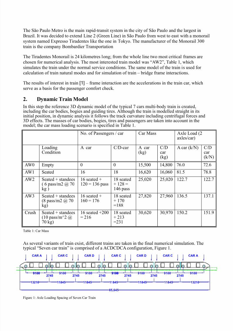
2. Dynamic Train ModelIn this step the reference 3D dynamic model of the typical 7 cars multi-body train is created,including the car bodies, bogies and guiding tires. Although the train is modelled straight in itsinitial position, in dynamic analysis it follows the track curvature including centrifugal forces and3D effects. The masses of car bodies, bogies, tires and passengers are taken into account in themodel; the car mass loading scenario is specified in Table 1.
No. of Passengers / car Car Mass Axle Load (2axles/car)
LoadingCondition
A car C/D-car A car(kg)
C/Dcar(kg)
A car (k/N) C/Dcar(k/N)
AW0 Empty 0 0 15,500 14,800 76.0 72.6
AW1 Seated 16 18 16,620 16,060 81.5 78.8AW2 Seated + standees
( 6 pass/m2 @ 70kg )
16 seated +120 = 136 pass
18 seated+ 128 =146 pass
25,020 25,020 122.7 122.7
AW3 Seated + standees(8 pass/m2 @ 70kg)
16 seated +160 = 176
18 seated+ 170=188
27,820 27,960 136.5 137.1
Crush Seated + standees(10 pass/m^2 @70 kg)
16 seated +200= 216
18 seated+ 213=231
30,620 30,970 150.2 151.9
Table 1: Car Mass
As several variants of train exist, different trains are taken in the final numerical simulation. Thetypical “ Seven car train” is comprised of a ACDCDCA configuration, Figure 1.
Figure 1: Axle Loading Spacing of Seven Car Train
9100 91002745
910091002745
91002745
91002745
9100 91002745
91002745
CAR A CAR ACAR C CAR C CAR CCAR D CAR D
13210 11845 11845 11845 132101184511845
85,645
8/10/2019 Dynamic Train -Bridge Interaction
http://slidepdf.com/reader/full/dynamic-train-bridge-interaction 3/8
8/10/2019 Dynamic Train -Bridge Interaction
http://slidepdf.com/reader/full/dynamic-train-bridge-interaction 4/8
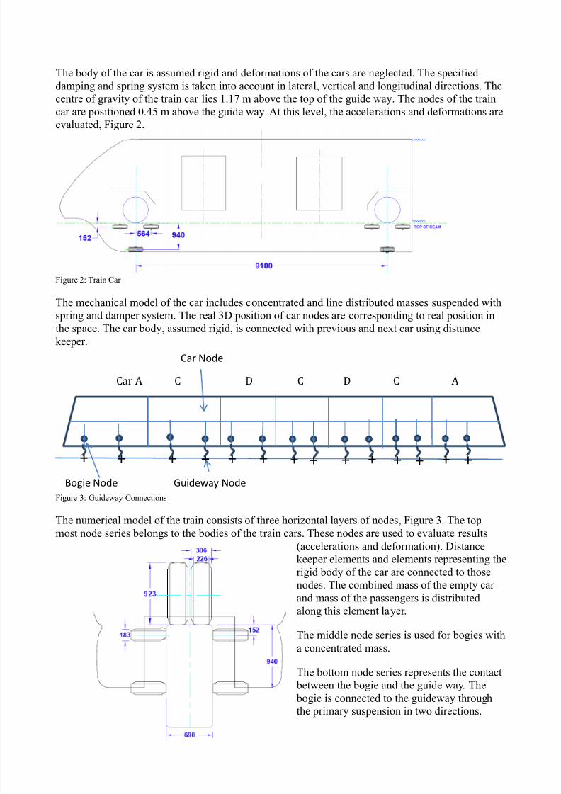
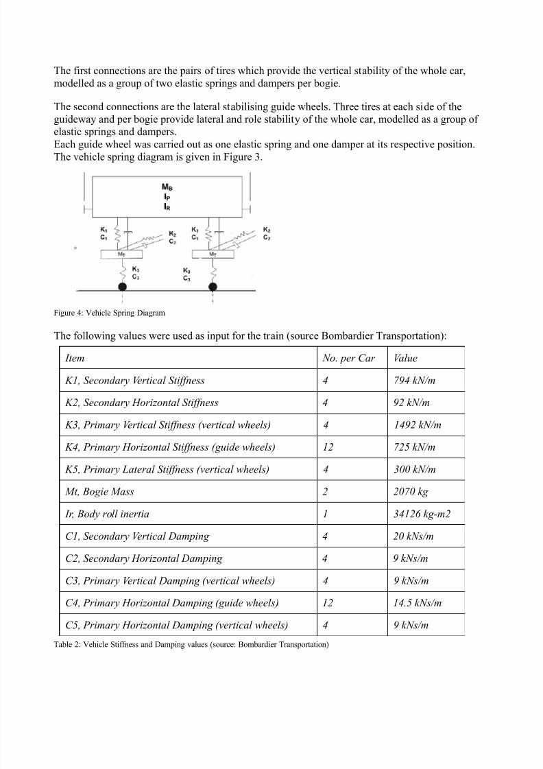
The first connections are the pairs of tires which provide the vertical stability of the whole car,modelled as a group of two elastic springs and dampers per bogie.
The second connections are the lateral stabilising guide wheels. Three tires at each side of theguideway and per bogie provide lateral and role stability of the whole car, modelled as a group of
elastic springs and dampers.Each guide wheel was carried out as one elastic spring and one damper at its respective position.The vehicle spring diagram is given in Figure 3.
Figure 4: Vehicle Spring Diagram
The following values were used as input for the train (source Bombardier Transportation):
Item No. per Car Value
K1, Secondary Vertical Stiffness 4 794 kN/m
K2, Secondary Horizontal Stiffness 4 92 kN/m
K3, Primary Vertical Stiffness (vertical wheels) 4 1492 kN/m
K4, Primary Horizontal Stiffness (guide wheels) 12 725 kN/m
K5, Primary Lateral Stiffness (vertical wheels) 4 300 kN/m
Mt, Bogie Mass 2 2070 kg
Ir, Body roll inertia 1 34126 kg-m2
C1, Secondary Vertical Damping 4 20 kNs/mC2, Secondary Horizontal Damping 4 9 kNs/m
C3, Primary Vertical Damping (vertical wheels) 4 9 kNs/m
C4, Primary Horizontal Damping (guide wheels) 12 14.5 kNs/m
C5, Primary Horizontal Damping (vertical wheels) 4 9 kNs/m
Table 2: Vehicle Stiffness and Damping values (source: Bombardier Transportation)

8/10/2019 Dynamic Train -Bridge Interaction
http://slidepdf.com/reader/full/dynamic-train-bridge-interaction 5/8
3. Calibration of the Train Model Natural modes and frequencies are calculated for train mechanical model consisting of seven cars.The calculated results have been validated against the references given by the manufacturer of thetrain (Bombardier Transportation).After the model calibration process, where the modelling details have been updated to fit the latesttrain design changes, good agreement is reached.
Mode
Natural Frequency (Hz)
SPET
AW0 AW3
LONGITUDINAL
Carbody Fore-Aft (Two trucks are fixed) 15.80 14.00
Truck Fore-Aft (The carbody is fixed) 13.21 12.80
VERTICAL
Carbody Roll 1.03 1.31Carbody Bounce 1.96 1.51
Carbody Pitch 3.00 2.50
Truck Bounce 7.12 8.00
LATERAL
Upper Roll Center 1.43 1.07
Carbody Yaw 1.59 1.12
Table 3: Reference Vehicle Natural Frequencies (source: Bombardier Transportation)
4. Bridge Model
As third step the bridge is modelled including superstructure and substructure. Special care is givento the realistic modelling of the transverse behaviour as the train path is fully eccentric to the bridgecentre line.
Figure 5: Numerical Model of the Curved Frame
The curved frame (Figure 4) is approximately 120 m long and has 4 spans. This frame is chosen to

8/10/2019 Dynamic Train -Bridge Interaction
http://slidepdf.com/reader/full/dynamic-train-bridge-interaction 6/8
analyse the influence of the centrifugal force on the overall behaviour of the frame. This centrifugalforce originates from mass and speed of the travelling train and the horizontal radius of the frame.The horizontal radius of the curved frame varies from 741 m at the beginning, to 362 m in themiddle, to 1899 m at the end of the frame.
According to AASHTO LRFD 2005 C4.7.1.4, the Rayleigh damping of 2% was used. This damping
value was set at the frequencies 1.92 Hz and 6.52 Hz. The respective values for Alpha (structuralstiffness damping ratio) is 0.3184 and for Beta (mass damping ratio) 0.0007023.
5. Interaction between the Train and the Bridge
The interaction between the bridge and the vehicles moving over the bridge is a coupled, nonlineardynamic problem. In the simplest model [2], especially when the vehicle to bridge mass ratio issmall, the elastic and inertial effects of the vehicles are ignored; this case is usually referred as themoving load model [3]. For cases where the inertia of the vehicle cannot be regarded as small, amoving mass model should be adopted instead. One drawback with the moving mass model is thatit excludes consideration of the bouncing action of the moving mass relative to the bridge.
Moving load model
Moving mass model
Sprung mass model
Train-track-bridge interaction
Figure 6: Different interaction models
Therefore the next modelling level is moving mass supported by a spring-dashpot unit, so calledsprung mass model (moving oscillator). The most complex modelling approach is the full train-track-bridge interaction with fully coupling of the train, track and bridge static and dynamic effects.
The latest approach has been used in this work. Special computer software has been developedwhich carries numerical simulation of the train-bridge interaction. Within time history analysis [4],
based on the Newmark method, the node contact layer of guideway is coupled in train and bridge

8/10/2019 Dynamic Train -Bridge Interaction
http://slidepdf.com/reader/full/dynamic-train-bridge-interaction 7/8
model. Contact forces are transferred from the train model to the bridge; bridge movements atcontact node layer are introduced as a base displacement in the train model.
Using developed computer software, train/frame interaction is investigated with two frame types – straight frame and curved frame. The goal was to investigate the comfort criteria - vertical and
lateral accelerations - in the train passenger compartment. The full interaction of the 3D framestructure and 3D train model is taken into account. The limits according to design criteria are givenas 5% G - earth gravity (0.4905 m/s2) for vertical acceleration and 10% G (0.981 m/s2) for lateralacceleration.
5.1 Curved Frame
The curved frame is chosen due to its narrow horizontal curve. The maximum lateral centrifugalacceleration, which is the result of the horizontal curvature of the frame and the maximum speed ofthe train, is 0.412 m/s2. The maximum lateral acceleration of the train car due to the frame vibration(interaction) at the maximum speed is 0.038 m/s2.
The major lateral acceleration component comes from the centrifugal acceleration, representingapproximately 90% of the total sum. The dynamic component due to the train/frame interaction is ata 10% level. The total lateral acceleration (centrifugal acceleration + dynamic acceleration due tothe frame vibration) reaches the value of 0.45 m/s2.
The vertical acceleration is the direct result of the train/frame dynamic vibration. On the curvedframe it reaches a maximum value of 0.13 m/s2, which is only 13% of the prescribed limit.
The lateral acceleration is a combined result of the train/frame dynamic vibration and centrifugalacceleration. The lateral acceleration reaches a maximum value of 0.45 m/s2, which is 46% of the
prescribed limit.
Figure 7: Curved frame: Envelope of Vertical Acceleration for All Speeds (Train and Bridge)
5.2 Straight Frame
The straight frame is chosen due to its asymmetric pier geometry and the relatively high speeds ofthe train. Due to asymmetric piers, the right guide way has a large eccentricity. The vertical loading
produces relatively high lateral bending moments in the piers. This effect is clearly confirmed in thenumerical simulation.

8/10/2019 Dynamic Train -Bridge Interaction
http://slidepdf.com/reader/full/dynamic-train-bridge-interaction 8/8
The straight frame has smaller horizontal curvature – bigger radius. Therefore the maximal lateralcentrifugal acceleration is 0.308 m/s2 (compared to 0,412m/s2 for curved frame). The maximumlateral acceleration of the train car due to the frame vibration (interaction) at the maximum speed is0.112 m/s2. The combined lateral acceleration (centrifugal acceleration + acceleration due to framevibration) is 0.42 m/s2. The total effect is therefore smaller than in curved frame.
The centrifugal acceleration represents around 75% of the total sum of the lateral acceleration. Theremaining 25% come from the train/frame vibration. As expected, the dynamic effects become moredominant, with the increasing speed of the train.
For the maximal design speed, the vertical acceleration remains well below the prescribed limit,reaching only 0.43 m/s2, providing 13% reserve to the limit.
The lateral acceleration is a combined result of the train/frame dynamic vibration and centrifugalacceleration. The lateral acceleration reaches a maximum value of 0.42 m/s2, which is only 43% ofthe prescribed limit.
6. Conclusion
For the purpose of the train/bridge interaction, special computer software has been developed.Within time history analysis, based on the Newmark method, the node contact layer of guideway iscoupled in train and bridge model. Contact forces are transferred from the train model to the bridge;
bridge movements at contact node layer are introduced as a base displacement in the train model.
Using developed computer software, train/frame interaction is investigated with two frame types – straight frame and curved frame. The goal was to investigate the comfort criteria - vertical andlateral accelerations - in the train passenger compartment.
The numerical simulation shows that the acceleration comfort criteria is well within the limitsexcept for the maximal design speed on the straight frame, where the maximum verticalacceleration shows 14% higher values at the time when the train axis enters/leaves the bridge. It isexpected that this local phenomena is smaller in reality if the flexibility of neighbour frame is
partially taken into account.
7. References[1] TDV Project Documentation “ Innova Tiradentes Report” - 2011
[2] Janjic, D., Stampler, J., Domaingo, A. , “Dynamic Response of Filler Beam Bridges duringTrain Transit ”, Proceedings: Eurosteel Conference 3-5 Sept. 2008, Graz, Austria
[3] Janjic D., Stampler, J., Handel, C. "Standardized Serviceability Tests of Railway Bridges", Proceedings: EVACES Conference 24-26 Oct., 2007, Porto, Portugal
[4] Janjic D., “Dynamic Response of The Bridge due to the Moving Vehicle”, Master Thesis1989, the Faculty of Civil Engineering, Sarajevo