Dynamic stress intensity factors for a longitudinal semi ...
21
MultiCraft International Journal of Engineering, Science and Technology Vol. 6, No. 5, 2014, pp. 57-77 INTERNATIONAL JOURNAL OF ENGINEERING, SCIENCE AND TECHNOLOGY www.ijest-ng.com www.ajol.info/index.php/ijest 2014 MultiCraft Limited. All rights reserved Dynamic stress intensity factors for a longitudinal semi-elliptical crack in a thick-walled cylinder S. M. Nabavi 1,* , A. R. Shahani 2 1 Department of Aerospace Engineering, M. U. T., Garmdareh, Alborz, IRAN 2 Faculty of Mechanical Engineering, K. N. T. University of Technology, Tehran, IRAN * Corresponding Author: e-mail: [email protected], Tel: +98-26-36105190, fax: +98-26-36102455 Abstract The dynamic stress intensity factors are derived for an internal longitudinal semi-elliptical crack in a thick-walled cylinder subjected to transient dynamic stresses. First, the problem of dynamic elasticity in a thick-walled cylinder is solved analytically using the finite Hankel transform. Transient pressure is assumed to act on the inner and outer surfaces of the cylinder. Then, a three-dimensional finite element method is used to calculate accurate weight functions for semi-elliptical surface crack in the cylinder. Finally, the dynamic stress intensity factors are extracted for both the deepest and surface points of the semi-elliptical crack using the weight function method. An effective and accurate process of computing closed-form stress intensity factors is employed which can be used for any kind of boundary conditions. It is shown that for narrow cracks, the deepest point is always the starting point of any problem crack propagation. However, for cracks with high aspect ratios, the critical point of the crack front displaces between the deepest to the surface point in different instants of time. Keywords: Semi-Elliptical Crack – Weight Function – Thick-Walled Cylinder – Dynamic stress intensity factor – Hankel Transform. DOI: http://dx.doi.org/10.4314/ijest.v6i5.6 1. Introduction More real structural elements contain crack-like defects located in the most critical area of the component in the most unfavorable orientation. When a cracked cylinder is subjected to dynamic loading, it is important to determine the corresponding stress intensity factor as a first step towards fracture prediction. Practical aspects of the problem involve actual structures subjected to transient dynamic loading. Lin and Smith (1998) have obtained that during crack growth, initially irregular crack front will rapidly become approximately semi-elliptical, so the geometrical shape of a surface defect can conform to elliptical geometry. Based on the elastic analysis, Sheng (1965) analyzed elastic flexural displacements and stresses of a simply supported, thin circular cylindrical shell of finite length subjected to transient surface loading using Williams' method. Suzuki (1988) has carried out stress analysis for a finite cylinder subjected to arbitrary distributed axisymmetrical surface loads using the variational principle of complementary energy. Okumura (1989) used the generalized Elliott’s function for stress analysis of a transversely isotropic, short hollow cylinder under an outer band load. Wang and Gong (1991) analyzed a dynamic solution of hollow cylinders with homogeneous boundary conditions by utilizing the finite Hankel transform and Laplace transform. Yin and Yue (2002) presented the transient response of a multilayered cylinder subjected to uniformly distributed dynamic pressures at the boundaries, using the expansion of transient wave functions in a series of eigenfunctions. Leishear (2007) used a finite element analysis to determine the three-dimensional dynamic stresses for modeling a moving shock wave in a pipe. The evolution of the stress intensity factor in cracked cylinders addresses in some references. Atluri and Kathiresan (1979) determined the stress intensity factors for external and internal pressurized surface cracks in a long cylinder using a three- dimensional hybrid finite element method. Tan and Fenner (1980) analyzed an internally pressurized thick-walled cylinder with a semi-elliptical crack using the boundary integral equation method. Newman and Raju (1980;1982) calculated the stress intensity
Transcript of Dynamic stress intensity factors for a longitudinal semi ...

MultiCraft
International Journal of Engineering, Science and Technology
Vol. 6, No. 5, 2014, pp. 57-77
INTERNATIONAL JOURNAL OF
ENGINEERING, SCIENCE AND TECHNOLOGY
www.ijest-ng.com www.ajol.info/index.php/ijest
2014 MultiCraft Limited. All rights reserved
Dynamic stress intensity factors for a longitudinal semi-elliptical crack in a thick-walled cylinder
S. M. Nabavi1,*, A. R. Shahani2
1 Department of Aerospace Engineering, M. U. T., Garmdareh, Alborz, IRAN
2 Faculty of Mechanical Engineering, K. N. T. University of Technology, Tehran, IRAN *Corresponding Author: e-mail: [email protected], Tel: +98-26-36105190, fax: +98-26-36102455
Abstract The dynamic stress intensity factors are derived for an internal longitudinal semi-elliptical crack in a thick-walled cylinder subjected to transient dynamic stresses. First, the problem of dynamic elasticity in a thick-walled cylinder is solved analytically using the finite Hankel transform. Transient pressure is assumed to act on the inner and outer surfaces of the cylinder. Then, a three-dimensional finite element method is used to calculate accurate weight functions for semi-elliptical surface crack in the cylinder. Finally, the dynamic stress intensity factors are extracted for both the deepest and surface points of the semi-elliptical crack using the weight function method. An effective and accurate process of computing closed-form stress intensity factors is employed which can be used for any kind of boundary conditions. It is shown that for narrow cracks, the deepest point is always the starting point of any problem crack propagation. However, for cracks with high aspect ratios, the critical point of the crack front displaces between the deepest to the surface point in different instants of time. Keywords: Semi-Elliptical Crack – Weight Function – Thick-Walled Cylinder – Dynamic stress intensity factor – Hankel Transform. DOI: http://dx.doi.org/10.4314/ijest.v6i5.6 1. Introduction More real structural elements contain crack-like defects located in the most critical area of the component in the most unfavorable orientation. When a cracked cylinder is subjected to dynamic loading, it is important to determine the corresponding stress intensity factor as a first step towards fracture prediction. Practical aspects of the problem involve actual structures subjected to transient dynamic loading. Lin and Smith (1998) have obtained that during crack growth, initially irregular crack front will rapidly become approximately semi-elliptical, so the geometrical shape of a surface defect can conform to elliptical geometry.
Based on the elastic analysis, Sheng (1965) analyzed elastic flexural displacements and stresses of a simply supported, thin circular cylindrical shell of finite length subjected to transient surface loading using Williams' method. Suzuki (1988) has carried out stress analysis for a finite cylinder subjected to arbitrary distributed axisymmetrical surface loads using the variational principle of complementary energy. Okumura (1989) used the generalized Elliott’s function for stress analysis of a transversely isotropic, short hollow cylinder under an outer band load. Wang and Gong (1991) analyzed a dynamic solution of hollow cylinders with homogeneous boundary conditions by utilizing the finite Hankel transform and Laplace transform. Yin and Yue (2002) presented the transient response of a multilayered cylinder subjected to uniformly distributed dynamic pressures at the boundaries, using the expansion of transient wave functions in a series of eigenfunctions. Leishear (2007) used a finite element analysis to determine the three-dimensional dynamic stresses for modeling a moving shock wave in a pipe.
The evolution of the stress intensity factor in cracked cylinders addresses in some references. Atluri and Kathiresan (1979) determined the stress intensity factors for external and internal pressurized surface cracks in a long cylinder using a three-dimensional hybrid finite element method. Tan and Fenner (1980) analyzed an internally pressurized thick-walled cylinder with a semi-elliptical crack using the boundary integral equation method. Newman and Raju (1980;1982) calculated the stress intensity
Nabavi and Shahani / International Journal of Engineering, Science and Technology, Vol. 6, No. 5, 2014, pp. 57-77
58
factors for semi-elliptical surface crack in cylindrical pressure vessels by a three-dimensional finite element method. They employed different kinds of stress distribution on the crack surfaces in their papers. Sekine and Koizumi (1982) used the plane deformation theory of elasticity to obtain the stress intensity factors for an arbitrarily oriented line crack embedded in a pressurized thick-walled cylinder. The analysis is based on the dislocation method. Chen et al. (1995) solved the surface crack problem in a cylinder subjected to internal pressure using the body force method. A hybrid boundary element method was used by Guozhong et al. (1995a,b) for calculation of the stress intensity factor of surface cracks in finite thickness plates and cylinders. Wang (1995) computed dynamic stress intensity factors of different kinds of dynamic inner pressures in a thick walled cylinder. The finite element method was used for calculating dynamic stress intensity factors. The stress intensity factor of semi-elliptical axial cracks lying at the surface of hollow cylinders under non-uniform stress gradient at the crack face has been determined by Zheng et al. (1995) using the weight function method. Shahani and Nabavi (2005; 2006; 2007) have solved the mechanical and thermal stress intensity factors for both the deepest and the surface points of the semi-elliptical crack using the weight function method. Hachi et al. (2005) proposed a hybrid weight function technique for computation of the stress intensity factors of an elliptical crack in an infinite body and semi-elliptical cracks in thin and thick cylinders. The method consists of dividing the ellipse into two zones and then using the proper weight function in each area where it is more efficient. Shlyannikov (2000) simulated the fatigue crack shape through a theoretical model for part-through cracks in a hollow cylinder under cyclic pressure and the propagation path of the surface flaw was obtained as a diagram. Kamaya and Nishioka (2005) developed an analysis system using the finite element alternating method for evaluating the stress intensity factors of surface cracks in a cylinder. Chen et al. (2009) evaluated dynamic stress intensity factors for thick-walled cylinder with a radial edge crack under internal impulsive pressure using the weight function method.
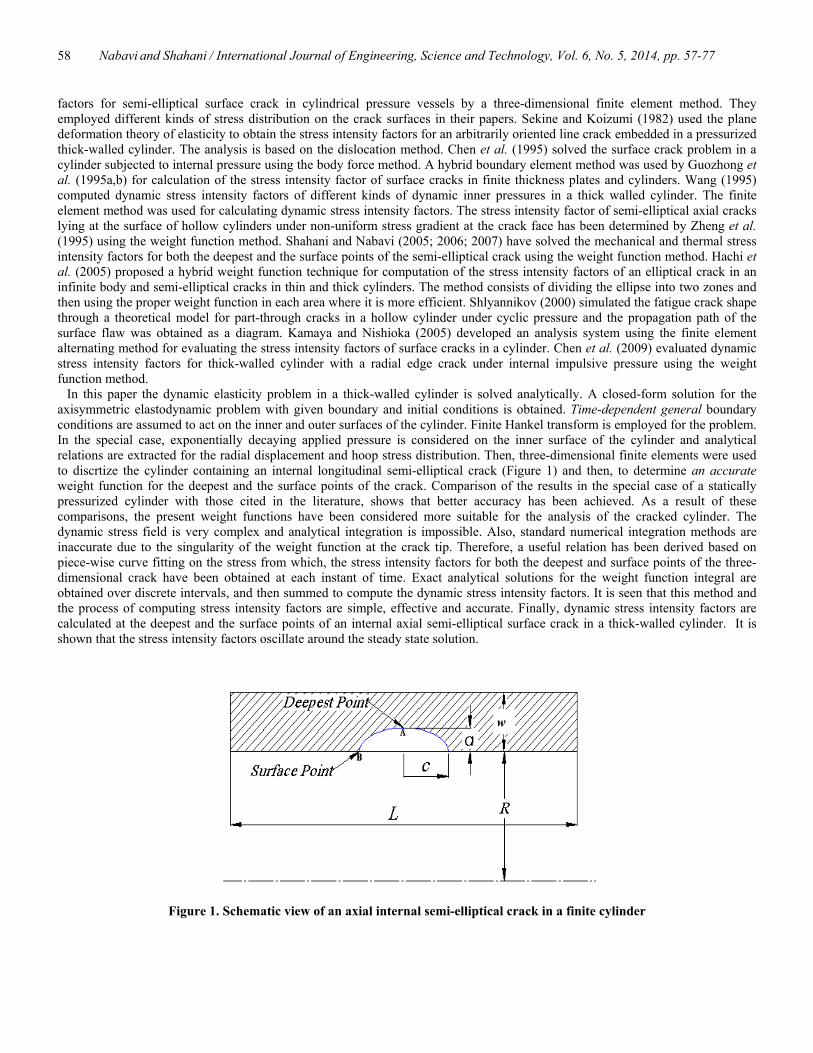
In this paper the dynamic elasticity problem in a thick-walled cylinder is solved analytically. A closed-form solution for the axisymmetric elastodynamic problem with given boundary and initial conditions is obtained. Time-dependent general boundary conditions are assumed to act on the inner and outer surfaces of the cylinder. Finite Hankel transform is employed for the problem. In the special case, exponentially decaying applied pressure is considered on the inner surface of the cylinder and analytical relations are extracted for the radial displacement and hoop stress distribution. Then, three-dimensional finite elements were used to discrtize the cylinder containing an internal longitudinal semi-elliptical crack (Figure 1) and then, to determine an accurate weight function for the deepest and the surface points of the crack. Comparison of the results in the special case of a statically pressurized cylinder with those cited in the literature, shows that better accuracy has been achieved. As a result of these comparisons, the present weight functions have been considered more suitable for the analysis of the cracked cylinder. The dynamic stress field is very complex and analytical integration is impossible. Also, standard numerical integration methods are inaccurate due to the singularity of the weight function at the crack tip. Therefore, a useful relation has been derived based on piece-wise curve fitting on the stress from which, the stress intensity factors for both the deepest and surface points of the three-dimensional crack have been obtained at each instant of time. Exact analytical solutions for the weight function integral are obtained over discrete intervals, and then summed to compute the dynamic stress intensity factors. It is seen that this method and the process of computing stress intensity factors are simple, effective and accurate. Finally, dynamic stress intensity factors are calculated at the deepest and the surface points of an internal axial semi-elliptical surface crack in a thick-walled cylinder. It is shown that the stress intensity factors oscillate around the steady state solution.
Figure 1. Schematic view of an axial internal semi-elliptical crack in a finite cylinder
w

Nabavi and Shahani / International Journal of Engineering, Science and Technology, Vol. 6, No. 5, 2014, pp. 57-77
59
2. Derivation of the dynamic stress field
2.1. Statement of the problem
Consider the axisymmetric problem of a hollow circular cylinder subjected to transient pressure on the inner and outer surfaces. Let iR and oR denote the inner and outer radii of the cylinder, respectively. The cylinder is made of a homogeneous isotropic material and is long enough in the axial direction such that the assumption of the plane strain condition satisfies. Hence, the only non-zero component of the displacement field is the radial one which is a function of radial coordinate and time; ),( truu = . The equations of motion in the absence of body force reduce to the single equation:
2
22
22
2 1tu
ru
ru
rru
∂∂
=−∂∂
+∂∂ γ (1-a)
)1(2)21(2
vv
−−
=µργ (1-b)
In which ρ is the density, v the Poisson’s ratio and µ the shear modulus of the material of the cylinder. The non-vanishing stress components are rσ and θσ which are related to the displacement component as follows:
+
∂∂
−−
=ruv
ruv
vr )1(21
2µσ (2-a)
∂∂
+−−
=ruv
ruv
v)1(
212µ
σθ (2-b)
It is assumed that the inner and outer surfaces of the cylinder are subjected to arbitrary transient pressure, i.e.: )(),( tftR iir −=σ (3-a) )(),( tftR oor −=σ (3-b)
where )(tfi and )(tfo are known functions of time representing the transient surface traction on the surfaces of the cylinder. The initial conditions of the cylinder are:
0)0,( =ru (4-a)
00
=∂∂
=ttu (4-b)
2.2. Mathematical method of solution
Noting the governing differential equation of the problem, Eq. (1-a), it is seen that it contains a linear operator L of the form
frr
frrr
Lf2
1 1−
∂∂
∂∂
= (5)
Therefore, the solution of the problem may be accomplished using the finite Hankel transform, defined by the following relation (Sneddon, 1972)
∫==o
i
R
R nnn drrKtrfrtrfHtF ),( ),(]);,([),( λλλ (6)
where nλ is the transform parameter and ),( nrK λ is the kernel of the transformation. The inverse transform is defined as (Sneddon, 1972)
),( ),(]);,([),(1
1-nn
nnn rKtFartFHtrf λλλ ∑
∞
=
== (7)
where
∫=
o
i
R
R n
n
drrKra
)],([
12λ
(8)
The choice of a proper kernel depends on the form of the governing differential equation and boundary conditions of the
problem. With the given form of Lf (Eq. (5)), the kernel of the transformation appears as (Sneddon, 1972) )( )( ),( 11 rYBrJArK nnn λλλ += (9)
If the boundary conditions of the problem are defined by the linear operators M and N as:
Nabavi and Shahani / International Journal of Engineering, Science and Technology, Vol. 6, No. 5, 2014, pp. 57-77
60
)()( 21 iri RfaRfaMf += (10-a) )()( 21 oro RfbRfbNf += (10-b)
where rf stands for rf ∂∂ / , then the constants A and B of the kernel and the values of the characteristic roots, nλ , may be obtained from the following relations:
0),( =niRMK λ (11-a) 0),( =noRNK λ (11-b)
Applying the finite Hankel transform (6) to the linear operator (5) and twice integrating by part, yield )],(),(),(),([)],(),(),(),([),(];[ 2 tRfRKtRfRKRtRfRKtRfRKRtFLfH ornoonoroirniinirinnn λλλλλλλ −−−+−= (12)
Comparing Eqs. (3), though the use of (2), with (10) it is concluded that the conditions (11) can be written for this problem as
0)1(21
2=
∂∂
−+− = iRrr
KvKrv
vµ (13-a)
0)1(21
2=
∂∂
−+− = oRrr
KvKrv
vµ (13-b)
The corresponding kernel of the Hankel transform may then be obtained, using Eqs. (9) and (13-a), as follows
+
−−
−
+
−−
= )()()1(12)()()(
)1(12)(),( 011011 innin
ininnin
inn RJRJ
RrYRYRY
RrJrK λλλ
ννλλλλ
ννλλ (14)
The characteristic values, nλ , depend on the form of boundary conditions (Eqs. (9) and (13-b)) which are the n-th positive roots of the transcendental equation:
0)()()1(12)()(
)1(12
)()()1(12)()(
)1(12
0101
0101
=
+
−−
+
−−
−
+
−−
+
−−
innini
onnono
onnono
innini
RJRJR
RYRYR
RJRJR
RYRYR
λλλννλλλ
νν
λλλννλλλ
νν
(15)
Comparing the Eq. (5) with Eq. (1-a), it is concluded that fu = . So, by applying the Hankel transform (6) with the kernel (14) on Eq. (1-a) and using Eq. (12), yield
)],(),(),(),([)],(),(),(),([),(22
22 tRuRKtRuRKRtRuRKtRuRKRtu
dtud
ornoonoroirniinirinn λλλλλλγ −−−+−= (16) where
)],([),( truHtu n =λ (17) On the other hand, using Eqs (13) it is concluded after some mathematical manipulations:
),()1(
),( nii
nir RKvR
vRK λλ−
−= (18-a)
),()1(
),( noo
nor RKvR
vRK λλ−
−= (18-b)
Also, using the properties of the Bessel functions, the following identity holds true (Spiegel, 1990)
ψπψψψψ
2)()()()( 1001 =− YJYJ (19)
Applying the boundary conditions (3) on Eq. (16) and substituting Eqs. (18) and (19) into the right hand side of (16), result in
−
−−
=+ )(),()(2)1(2
)21(22
22 tfRKRtfu
dtud
onooin λπνµ
νλγ (20)
The solution of Eq. (20) may be obtained, by applying the initial conditions (4), as
∫
−
−
−−
=t
nonooi
nn dtSinfRKRftu
0)( )(),()(2
)1(2)21(),( ττ
γλ
τλτπλγνµ
νλ (21)
Now, applying the inverse transform (7), with (Sneddon, 1972)
n
onnono
n
n b
RJRJR
a 2
)()()1(12
2
0122
+
−−
=λλλ
ννλπ
(22)
Nabavi and Shahani / International Journal of Engineering, Science and Technology, Vol. 6, No. 5, 2014, pp. 57-77
61
in which (Sneddon, 1972) 2
0122
2
0122 )()(
)1(12
))1((12)()(
)1(12
))1((12
+
−−
−
−+−
+
−−
−
−+= onnon
oininnin
ionn RJRJ
RRRJRJ
RRb λλλ
νν
ννλλλλ
νν
ννλ (23)
the dynamic displacement field in the cylinder will be obtained as follows
∑∞
=
=1
),( ),(),(n
nnn rKtuatru λλ (24) Applying Eq. (2-b), the hoop stress component can be derived as follows
∫∑
−
−×
Ψ
−+
−−
=∞
=
tn
onooin
nnn
n dtSinfRKRf)(r,λ)K(r,λr
atr0
1
)( )(),()(221
1 )1()21(),( ττ
γλτλτ
πνν
λγννσθ (25)
in which
+
−−
−
+
−−
=Ψ )()()1(12)()()(
)1(12)( 010010 innin
ininnin
inn RJRJ
RrYRYRY
RrJ)(r,λ λλλ
ννλλλλ
ννλ (26)
In the special case of exponentially decaying applied pressure on the inner surface of the cylinder and constant pressure on the outer one, we have
tii ePtf ω−= )( (27-a)
oo Ptf =)( (27-b) where iP , oP and ω are known constants. Substituting the above boundary condition into Eqs. (24), (25), the closed form relations for the radial displacement and hoop stress fields will be obtained as follows
−−
+
+−×
−−
=
−
∞
=∑
n
n
onoon
nnn
tn
in
nn
n
tCosPRKR
tSintCosePrKatru
λγλ
λγωλ
γλ
ωγγλ
λλ
πλ
λµνν
ω )(1),(
)()(2),(
)1(2)21(),(
2221
(28)
∑∞
=
Ψ
−+
−−
=1 21
1)1()21(),(
nnn
n
n )(r,λ)K(r,λr
atrν
νλν
νσθ
−−
+
+−×
−
n
n
onoon
nnn
tn
i
tCosPRKR
tSintCoseP
λγλ
λγωλ
γλ
ωγγλ
λλ
π
ω )(1),(
)()(2
222 (29)
3. Determination of weight functions
3.1. Finite element modeling
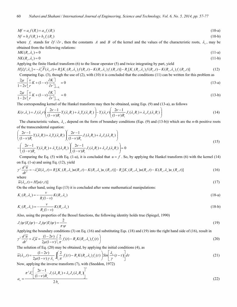
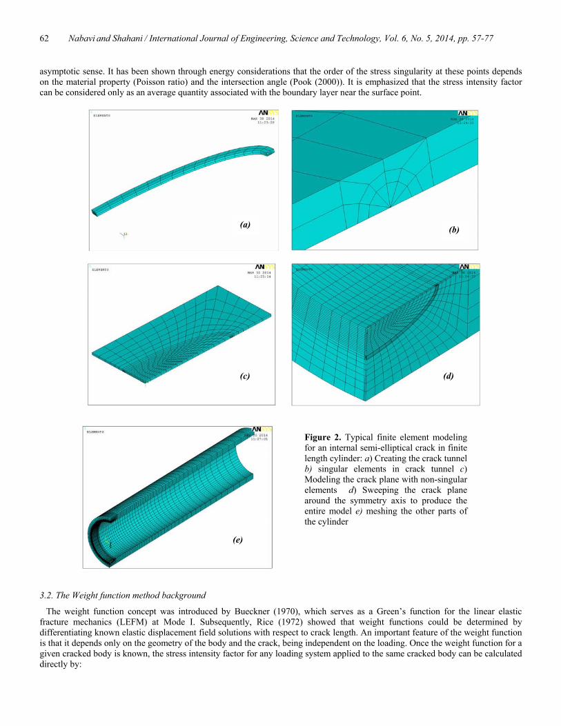
Three-dimensional finite elements were used to model the symmetric quarter of the cylinder containing an internal semi-elliptical crack (Figure 2-c). The finite element model is extracted by employing 20-node isoparametric brick elements in the ANSYS 11.0 standard code (2007). The square-root singularity of the stresses and strains is modeled by shifting the mid-point nodes to the quarter-point locations in the region around the crack front. The crack front region has been constructed by swiping an auxiliary area around the crack front line, as shown in Figure 2-a. Then, the created volume, which may be regarded as crack tunnel, is meshed using singular finite elements around the crack front and non-singular finite elements in the remaining part of the crack tunnel (Figure 2-b). After this stage, the cross-section of the cylinder on the cracked plane has been meshed and swept to create a 180 degrees model (Figure 2-c). As can be seen from Figure (2), the fine mesh is used in the vicinity of the crack tip and larger elements are used away from the crack tip. In the direction along the length of the cylinder, the mesh was graded to be fine near the crack front and coarse away from the crack front. For each value of crack geometry and cylinder length, the stress intensity factor may be obtained as a function of the displacements, as follow (Bank-Sills, 1991):
)(21
2 rr
KI δπκµ+
= (30)
where νκ 43−= for plane strain and ννκ +−= 1/)3( for plane stress, and )(rδ is the displacement normal to the crack plane at a distance from the crack tip which is computed along a line perpendicular to the crack front at each point.
The analyses on which the concept of stress intensity factor is based include the implicit assumption that the crack front is continuous. This is not the case at the corner point where a crack front intersects a free surface (Pook, 1994). The power of the crack tip singularity changes in the vicinity of a corner point, and it is only possible to define stress intensity factors in an
Nabavi and Shahani / International Journal of Engineering, Science and Technology, Vol. 6, No. 5, 2014, pp. 57-77
62
Figure 2. Typical finite element modeling for an internal semi-elliptical crack in finite length cylinder: a) Creating the crack tunnel b) singular elements in crack tunnel c) Modeling the crack plane with non-singular elements d) Sweeping the crack plane around the symmetry axis to produce the entire model e) meshing the other parts of the cylinder
(c)
(e)
(b)
(d)
(a)
asymptotic sense. It has been shown through energy considerations that the order of the stress singularity at these points depends on the material property (Poisson ratio) and the intersection angle (Pook (2000)). It is emphasized that the stress intensity factor can be considered only as an average quantity associated with the boundary layer near the surface point.
3.2. The Weight function method background
The weight function concept was introduced by Bueckner (1970), which serves as a Green’s function for the linear elastic fracture mechanics (LEFM) at Mode I. Subsequently, Rice (1972) showed that weight functions could be determined by differentiating known elastic displacement field solutions with respect to crack length. An important feature of the weight function is that it depends only on the geometry of the body and the crack, being independent on the loading. Once the weight function for a given cracked body is known, the stress intensity factor for any loading system applied to the same cracked body can be calculated directly by:

Nabavi and Shahani / International Journal of Engineering, Science and Technology, Vol. 6, No. 5, 2014, pp. 57-77
63
drarmrKa
new ),( )(0∫= σ (31)
where )(rσ is the stress distribution across the plane of the crack in the uncracked body and ),( arm is the weight function defined by:
axav
KHarm
∂∂
=),(),( (32)
in which H is a material constant, a is the crack length and ),( xav is the crack opening displacement. The weight function method, proposed by Bueckner (1970) and Rice (1972) for straight-through cracks, has been used also to estimate stress intensity factors for three-dimensional crack problems. Glinka and Shen (1991) have generated approximate weight functions in general form for semi-elliptical surface cracks in cylinders. The accuracy of this approach is depends on the reference load system applying to a cracked body to derive its coefficients.
3.3. Weight function for the deepest and surface points
It is important to note that the weight function is valid for one-dimensional stress distributions, which are functions of only one coordinate )(r . For the deepest point of an internal semi-elliptical surface crack the weight function is given as (Zheng et al., 1995)
)(212212),( 3321 raRa
MraRa
Ma
MraR
arm iAiAAi
A −++−+++−+
=ππππ
(33)
where the crack tip is at aRr i += , and the constants AiM can be derived using two reference stress intensity factor solutions and a third condition. The third condition for the deepest point is that the second derivative of the weight function is zero at iRr = (Fett et al., 1987). For the surface point of the semi-elliptical crack the weight function can be written as (Zheng et al., 1995)
)(414414),( 3321 iBiBBi
B Rra
MRra
Ma
MRr
arm −+−++−
=ππππ
(34)
where the crack tip is at aRr i += , and the constants BiM can similarly be derived using two reference stress intensity factor solutions and a third condition (Fett et al., 1987). The third condition for the surface point is that the weight function is equal to zero at aRr i += . Note that the singularity at the corner points of the semi-elliptical crack, in spite of other points on the crack front, deviates from the familiar square root singularity. But this is restricted to a small region around the surface points and the weight function leads to acceptable results for the stress intensity factor near the corner points. In order to calculate the stress intensity factors, it is necessary to determine the parameters AiM and BiM in the weight functions. The parameters AiM and BiM can be derived using two reference stress intensity factors and some properties of the weight functions for each point. The two reference stress intensity factor solutions used to derive the weight functions are constant and linear stress distributions as follows (Zheng et al., 1995):
0.1 )( σσ =rref (35-a)
)()( 0.2 aRrr i
ref
−=σσ (35-b)
The stress intensity factors for the two reference stress distributions in a thick-walled cylinder with 25.1/ =io RR , have been given for the deepest and surface points of the crack as follows (Zheng et al., 1995):
00.1 YQaK refA
πσ= (36-a)
10.2 YQaK refA
πσ= (36-b)
where 0Y and 1Y are boundary correction factors at the deepest point and Q is a semi-elliptical crack shape factor, approximated with the formula:
( ) 1/, /464.11 65.1 ≤+= cacaQ (37) The stress intensity factors corresponding to the surface points of the crack for the two above-mentioned reference stresses are as
follows (Zheng et al., 1995):
00.1 FQaK refB
πσ= (38-a)
Nabavi and Shahani / International Journal of Engineering, Science and Technology, Vol. 6, No. 5, 2014, pp. 57-77
64
10.2 FQaK refB
πσ= (38-b)
where 0F and 1F are boundary correction factors at the surface point. Substituting Eqs. (35) and (36) together with Eq. (33) into Eq. (31) and putting the second derivative of the weight function equal to zero, the constants AiM in Eq. (33) can be found as follows (Shahani and Nabavi, 2005):
( )
( )582
26
3
5243
22
103
2
011
−+−=
=
++−=
YYQ
M
M
YYQ
M
A
A
A
π
π
(39)
where ( ) ( ) ( )43
22100 /// waBwaBwaBBY +++= (40-a)
( ) ( ) ( )432
2101 /// waAwaAwaAAY +++= (40-b) in which
( )
( )
( )
( ) 3960.02670.05874.07673.38394.16311.1
1246.01503.1
/6256.23
/0433.42
/1582.01
/0867.00
+−=
−=
+−=
−=
−
−
−
−
ca
ca
ca
ca
eBeBeB
eB
(41)
and ( )
( )
( )
( ) 5930.00351.15864.02926.15363.12167.14821.19029.0
/0291.03
/2140.42
/0844.01
/064.00
−=
−=
+−=
+−=
−
−
−
−
ca
ca
ca
ca
eAeA
eAeA
(42)
In the same manner, substituting Eqs. (35) and (38) together with Eq. (34) into Eq. (32) and using the equation resulting from the fact that the weight function must be equal to zero at aRr i += , the constants BiM in Eq. (34) are obtained as follows (Shahani and Nabavi, 2006):
( )
( ) 15315
8523
102
011
++−=
−−=
FFQ
M
FFQ
M
B
B
π
π
( ) 81033103 −−= FF
QM B
π (43)
where
( ) ( ) ( )( )43
22100 /// waCwaCwaCC
caF +++= (44-a)
( ) ( ) ( )( )43
22101 /// waDwaDwaDD
caF +++= (44-b)
in which ( ) ( ) ( ) ( )432
0 /6597.8/9172.25/2260.29/6734.151808.4 cacacacaC +−+−=
( ) ( ) ( ) ( )4321 /1259.5/9300.15/7369.18/8971.90358.2 cacacacaC +−+−=
( ) ( ) ( ) ( )4322 /2612.6/0555.21/1884.28/1933.191716.6 cacacacaC +−+−=
( ) ( ) ( ) ( )4323 /1906.9/0184.28/2962.31/5873.147580.1 cacacacaC +−+−= (45)
and ( ) ( ) ( ) ( )432
0 /7871.0/2707.2/4425.2/3202.15642.0 cacacacaD +−+−=
( ) ( ) ( ) ( )4321 /7497.1/3985.5/2852.6/2653.35579.0 cacacacaD +−+−=

Nabavi and Shahani / International Journal of Engineering, Science and Technology, Vol. 6, No. 5, 2014, pp. 57-77
65
( ) ( ) ( ) ( )4322 /8079.1/2945.6/7677.8/2142.61670.2 cacacacaD +−+−=
( ) ( ) ( ) ( )4323 /1045.2/4290.6/1379.7/1846.32000.0 cacacacaD +−+−= (46)
4. Calculation of dynamic stress intensity factors
In the case of a continuously distributed stress field which is a function of coordinate r only, the transient thermal stress intensity factors can be extracted in closed-form, for both the deepest and the surface points of an internal longitudinal pressurized crack by the integration of the following formulas:
drarmtftraK A
aR
R inA
i
i
),( ))(),(()( ∫+
+= θσ (47-a)
drarmtftraK B
aR
R inB
i
i
),( ))(),(()( ∫+
+= θσ (47-b)
Here the difficulty in using Eq. (47) is that the integration cannot be carried out analytically due to the complexity of the mathematical form of the tangential stress distribution )),(( trθσ in Eq. (29). Some numerical integration methods were introduced by Moftakhar and Glinka (1992) and Kiciak (2003). In this paper an efficient integration technique is employed which is based on curve fitting on the hoop stress. In order to achieve to the best fitted curve, the hoop stress curve is divided to n portions at each time. Then, n second order polynomials are used to approximate the hoop stress in each portion at that time. Therefore, it is very convenient to approximate the stress distribution as a series of second order polynomials. Thus, the contribution to the stress intensity factor associated with the stress in the segment i can be calculated from Eq. (29). The approximation of the stress distribution with a second order polynomial can be given in the form of the following quadratic equation in i th segment
ζησ +≤≤+++= iiiiii RrRrCrBAr )( 2 (48) where iR is the inner radius of the cylinder and ηζ − is the length of i th segment in the r direction. After substituting appropriate expressions for the hoop stress in each segment, the closed form expressions resulting from the integration of Eq. (47) are obtained. The solutions given below have been derived for the deepest and the surface points of the semi-elliptical crack using the weight functions (33) and (34), respectively.
• Deepest point (A)
iAi
iAi
iAi
R
R Ai
R
R Ai
R
R Ai
R
R AiiiiA fCfBfAdrarmrCdrarmrBdrarmAdrarmrCrBAaK
i
i
i
i
i
i
i
i210
22 ),( ),( ),(),() ()( ++=++=++= ∫∫∫∫+
+
+
+
+
+
+
+
η
ζ
η
ζ
η
ζ
η
ζ
)21
322(2)()(),()()(),())(),(()( 321
11AAAin
n
i
iA
aR
R Ain
n
i
iAAin
aR
RA MMMatfaKdrarmtfaKdrarmtftraKi
i
i
i
++++=+=+= ∑∫∑∫=
+
=
+
πσθ (49)
where
( ) ( ) 3
22
33233
10 2)(28)()(
981)(2
AAAAiA Ma
aMaaMaa
aM
af
−+−+−−−+−−−+−=
ηζζηπ
ηζπ
ηζπ
ζηπ
(50-a)
( ) 1222
1 )(21221)(1)(2
3211
342
AiiA M
aaaR
aa
aa
aaaf ζη
πηζ
πηηη
ζζζ
πηζπ−+−−−+
−+−
−+−
−−
−=
222
12)32()32(2
152)(2 AAi Ma
aaa
aaMaR
a
−−+−−−++−+ ηηηζζζ
πζη
π
( ) 22)()(2
32 Ai MaaaaR
aηηζζ
π−−−−−+
( ) ( )
−+−+
−−−+ 3
22
232233
2 2)(2
21
312 AiA MaaR
aMa
aaηζζη
πηζηζ
π (50-b)
−−−−−
−−−−=
ηηηη
ζζζζ
π aaaa
aaaaf i
A
1)348(1)348(1522 32233223
2
( ) ( )
−−−−
−−−+
ηηη
ζζζ
π aaa
aaaRi
15521552154 2222

Nabavi and Shahani / International Journal of Engineering, Science and Technology, Vol. 6, No. 5, 2014, pp. 57-77
66
( ) ( ) 12
133
2
2 )(223122 AiAi M
aRM
aaa
aaR ζη
πζη
πηζ
π−+−+−−−+
( ) ( )( )
( ) 23223
2
23223
2
233
2
21
22
0571429.0285714.0076190.0152381.02
0571429.0285714.0076190.0152381.02
)()(2322
A
A
AiAi
Maaaaa
Maaaaa
Maaa
RMa
R
ηηηηπ
ζζζζπ
ηζπ
ζηπ
−+−+−
−+−++
−−−+−+
( ) ( )( ) 22222
2 32322154 Ai Maaaaaa
aR ηηηζζζ
π−−+−−−++
3
22
5
23
44332 2
)(2)(141)(
32 AiA Ma
aRM
aa
a
−+−+
−+−+
ηζζηπ
ζηζηπ
(50-c)
32
323
10 )(2
18)(198)(2
AAAnA Ma
aaMa
aMa
af ζ
πζ
πζ
πζ
π−+−+−+−= (50-d)
11 )2)((121)32(
234
AiinA MRaa
aRaaf ++−+++−= ζζ
πζζ
π
32
323 )32()(1
231)532()(1
2154 AiAi MRaa
aMRaa
a++−+++−+ ζζ
πζζ
π (50-e)
( ) ( ) 13322
2 )()(231 )(3))((4)(8
1522
AiiiiiiinA MRaR
aRRRRaRaaf +−+−++++++−= ζ
πζζζ
π
( ) 22223 35)32(1415128)(0152.0 Aii MRRaaaa
a+++++−+ ζζζζ
( ) 32222
3 6)2(432)(1261 Aii MRRaaaa
a+++++−+ ζζζζ
π (50-f)
• Surface point (B)
iBi
iBi
iBi
R
R Bi
R
R Bi
R
R Bi
R
R BiiiiB fCfBfAdrarmrCdrarmrBdrarmAdrarmrCrBAaK
i
i
i
i
i
i
i
i210
22 ),( ),( ),(),() ()( ++=+++=++= ∫∫∫∫+
+
+
+
+
+
+
+
η
ζ
η
ζ
η
ζ
η
ζ
)3424()()(),()()(),())(),(()( 321
11BBBin
n
i
iB
aR
R Bin
n
i
iBBin
aR
RB MMMatfaKdrarmtfaKdrarmtftraKi
i
i
i
++++=+=+= ∑∫∑∫=
+
=
+
πσθ (51)
where
( )
−+−+−+−= 3
22
233
10 21
32)()(22
BBBiB M
aMMaa
af ζηζηζηζη
π (52-a)
( ) ( ) ( )
−+−+
−+
−+−= 3
22
255
1
2233
1 2122
52
2322
Bi
BBiB M
aa
aRMMaa
af ζηζη
πζηζηζη
π
( )
−+−+
−+ 2
3313
33
32)(2
312 BB
iB MMa
aRM
aaζηζη
πζη
π (52-b)
( ) ( )
−+
−+−= 2
771
3355
2 285714.035
22BB
iB MMaa
af ζη
ζηζη
π
( )
−+−+
−+ 2
331
2
3
44
32)(
24
12 BBi
B MMaa
RM
aaζηζη
πζη
π

Nabavi and Shahani / International Journal of Engineering, Science and Technology, Vol. 6, No. 5, 2014, pp. 57-77
67
( ) ( )
−+
−+−+ 33
3
222
342
212
2 ζη
πζη
ζηπ
aa
RM
aa
aR i
Bi
( ) ( ) 32323
5333
255
122
32
3221
32
54)(2 AiBBB
i Maaa
RMa
MMaa
R
+−−+
−+−+−+ ηηζζ
πζηζηζη
π (52-c)
The first of equations (49) and (51) can be used for calculating the stress intensity contributions due to each second order approximation segment of the hoop stress distribution by substituting appropriate values for η and ζ . The stress intensity factor K is finally calculated as the sum of all contributions i
BAK , from all quadratic stress segments within the range aRrR ii +≤≤ . Most practical stress distributions can be superimposed by simple basic distributions. Thus, the applied stress acting on the surface flaw can be represented by this method and the stress intensity factor solution can be formulated in terms of some second order approximation segments which are fitted to stress distribution. The solution for stress intensity factor follows a series summation without any limitations. In this way, nonlinear stress variations can be assessed in the calculations by fitting more segments to achieve the best curve fitting without any effects on the accuracy of the solution.
5. Results and Discussion
The ratio of external to internal radii of the cylinder is 25.1/ =io RR and the material properties are assumed to be 3.0=ν and GPa 80=µ . The cylinder is subjected to transient exponentially decaying internal pressure (Eq. (27)) with MPaPi 10= , MPaPo 1.0= and 1.0=ω . The behavior of mechanical boundary condition (Eq. (27-a)) at the inner surface of the cylinder was
illustrated in Figure 3. As shown in Figure 3, the internal pressure varies with time and after about one minute the internal pressure decreases from its maximum )( iP to zero. The response to the exponential pressure loading, i.e., the dynamic hoop stress distribution along the radius of the uncracked cylinder at different instants of time is plotted in Figure 4. It is seen that the inertia term in dynamic elasticity equation influences the distribution of the dynamic stress in a manner that it possesses oscillatory behavior about the steady state solution (which corresponds to the case of neglecting the inertia term in elasticity equation) and it is not damped at all. It can be found that the boundary surface of the cylinder can reflect, scatter and refract the elastic waves, consequently resulting in the dynamic hoop stress varying with time periodically and oscillating around the value of the corresponding static hoop stress. In other words, the general feature of the dynamic circumferential stress is that it rises with time, reaching a peak and then decreasing in magnitude oscillating about its corresponding value under static loading. The static values may be found from the work of Timoshenko and Goodier (1987).
0
0.2
0.4
0.6
0.8
1
0 20 40 60 80 100
i
i
Ptf )(
time
Figure 3. Time-dependent variation of the mechanical condition on the inner surface of the cylinder

Nabavi and Shahani / International Journal of Engineering, Science and Technology, Vol. 6, No. 5, 2014, pp. 57-77
68
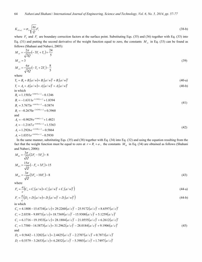
For the purpose of verification of the results, the extracted stress intensity factors have been compared with the results of finite element analysis and also with the published data in the literature when the cylinder is subjected to internal pressure. Two reference stress intensity factors were obtained by curve fitting for constant or linear stress distributions. The choice of functions is similar to that used in Zheng et al. (1995) and the curve fit is based on finite element data. In order to keep good accuracy while using reasonable computer resources all elements shape and aspect ratio for all meshes were checked to be converged. As a result of these trials it is anticipated that the level of error will be less than 2%. The stress intensity factors are computed both with the weight function extracted in the present work and that of Zheng et al. (1995). The results of this assessment are indicated in tables 1 and 2. It is observed that better accuracy has been achieved in the present work. As a result of these comparisons, the present weight functions were considered more suitable for the analysis of the cracked cylinder.
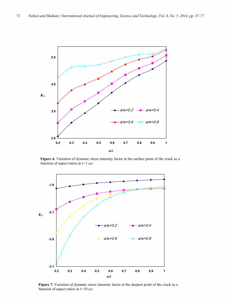
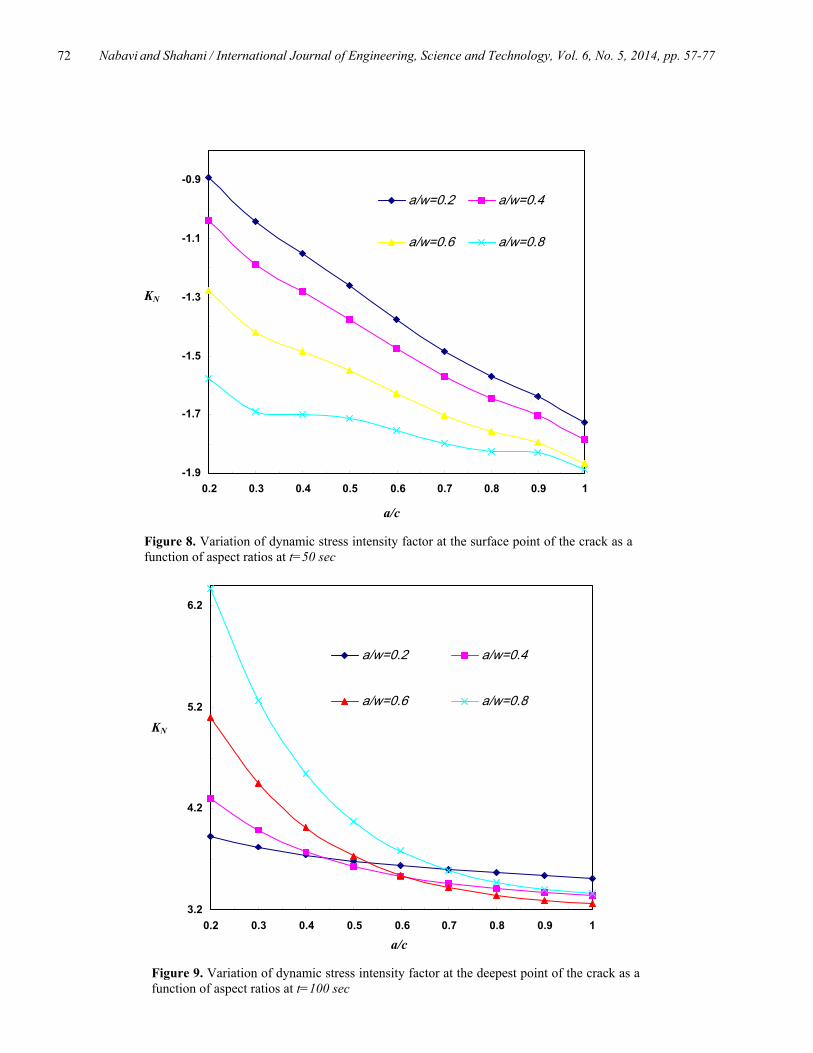
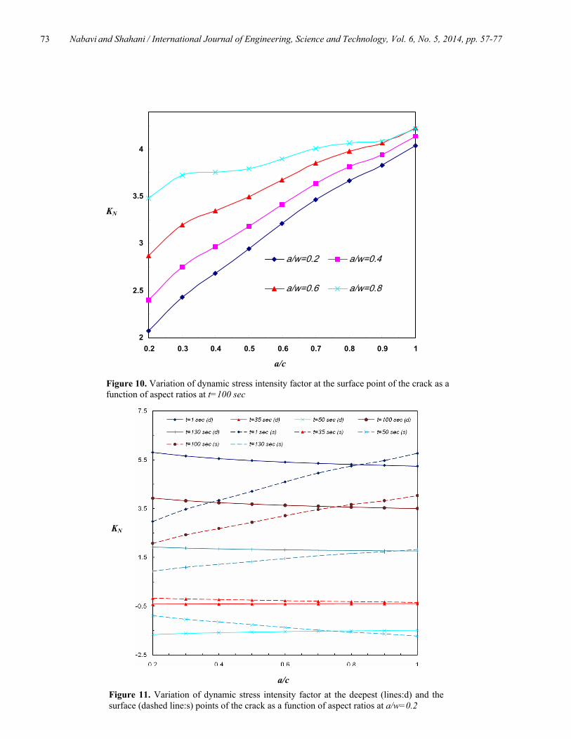
In order to evaluate the safety of the pressure vessel it is necessary to understand the histories of stress intensity factor distributions at the deepest and the surface points which will also be influenced by dynamic stress conditions. The non-dimensionalized dynamic stress intensity factors ))//(( QaPKK iIN π= are plotted in Figures 5 to 13 for different crack geometries and times. These geometries correspond to different aspect ratios )/( ca ranging from 0.2 to 1.0, and different relative depths )/( wa from 0.2 to 0.8. It could be seen from Figures 5 to 10 that the variations of distributions of transient stress intensity factors are complex. Because of fluctuating of the hoop stress, the maximum values of stress intensity factors are changed. It is observed that at some instants of time the deepest and surface points of the crack experience positive stress intensity factors and so lie in the opening mode (Figures 5, 6, 9, 10) while at some other instants because of the compressive nature of the resulting hoop stress in the cylinder thickness, the stress intensity factors are negative which means the so-called crack closure (e. g., Figures 7, 8). Dynamic loading of the cylinder causes a fluctuating behavior of the stress intensity factors at the deepest and the surface points of the crack. In both, the opening and closure modes, the behaviors of crack are similar. On the other hand, the absolute value of the stress intensity factor decreases at the deepest point as the aspect ratio increases in each times and for all crack relative depths; while it increases at the surface point with the increase in crack aspect ratio.
-45
-20
5
30
55
80
1 1.05 1.1 1.15 1.2 1.25
t=1 sec t=10 sec t=25 sec
t=35 sec t=50 sec t=90 sec
t=100 sec t=130 sec t=1000 sec
)( MPaθσ
Figure 4. Time-dependent distribution of the hoop stress versus the radial distance for exponentially decaying pressure on the inner boundary
r (m)
Nabavi and Shahani / International Journal of Engineering, Science and Technology, Vol. 6, No. 5, 2014, pp. 57-77
69
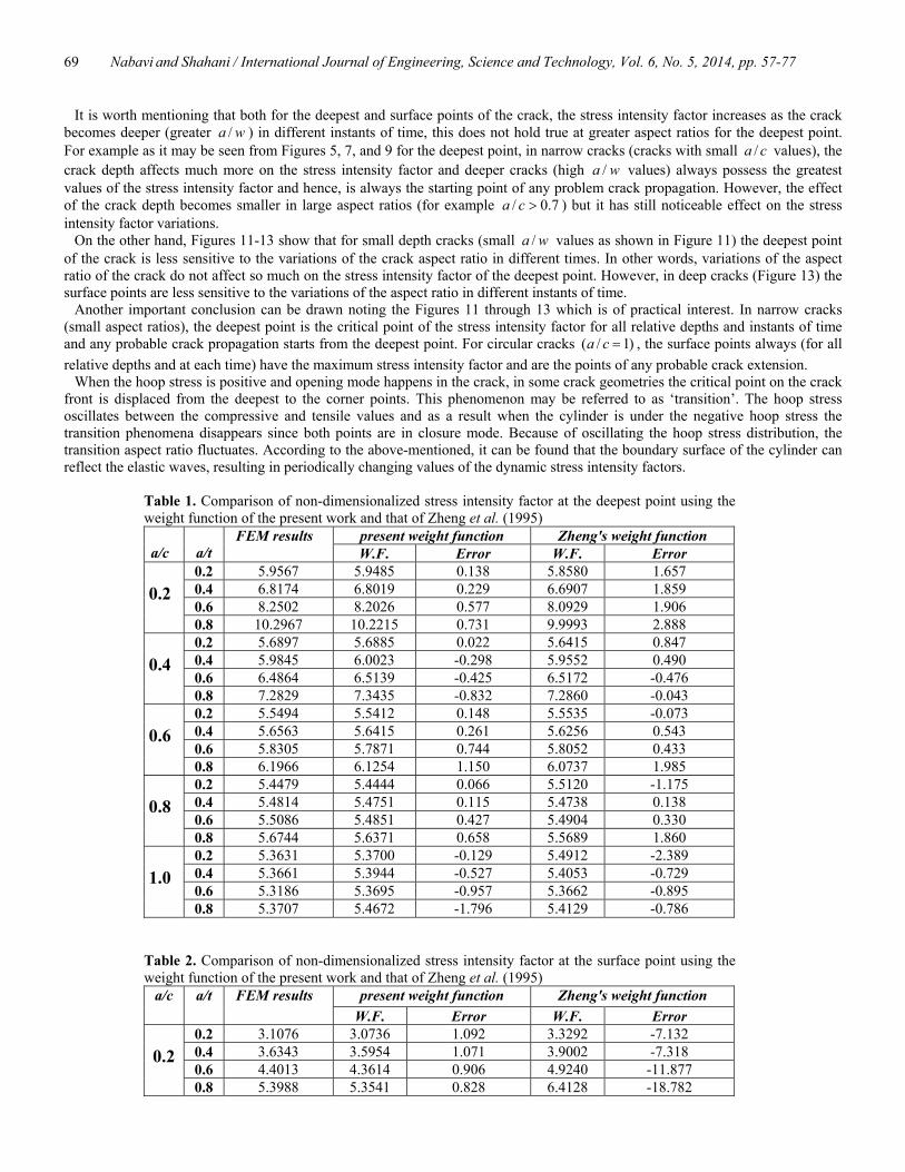
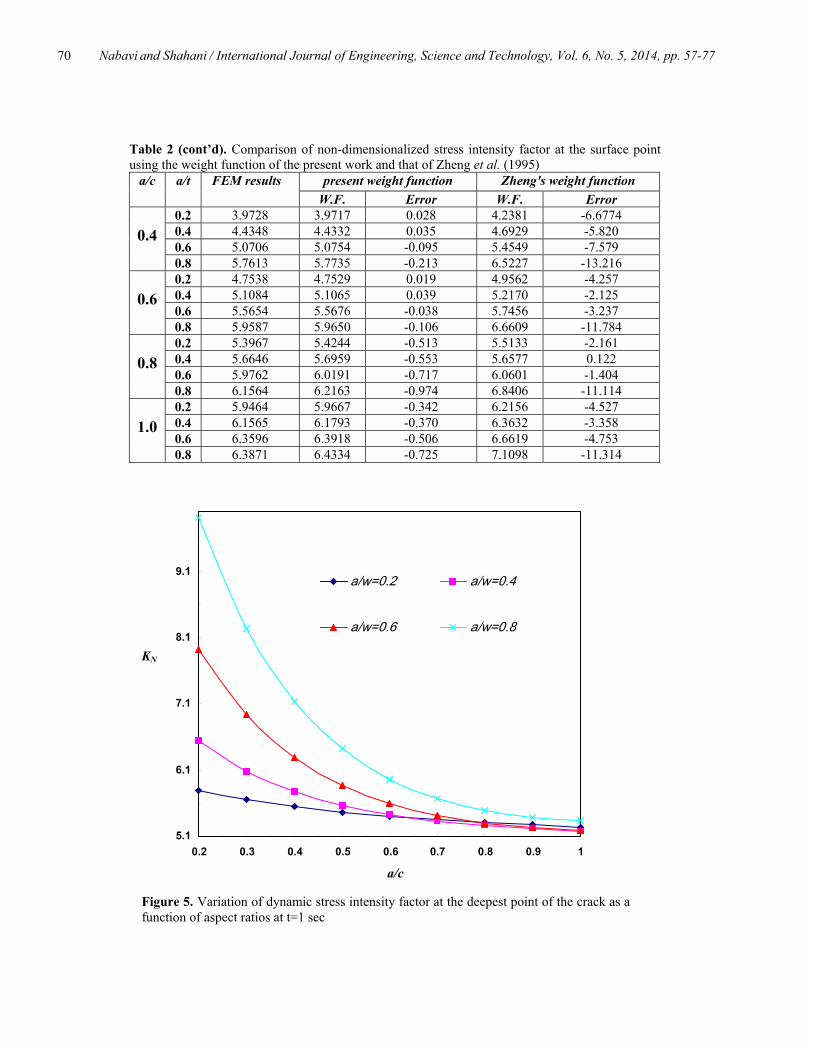
It is worth mentioning that both for the deepest and surface points of the crack, the stress intensity factor increases as the crack becomes deeper (greater wa / ) in different instants of time, this does not hold true at greater aspect ratios for the deepest point. For example as it may be seen from Figures 5, 7, and 9 for the deepest point, in narrow cracks (cracks with small ca / values), the crack depth affects much more on the stress intensity factor and deeper cracks (high wa / values) always possess the greatest values of the stress intensity factor and hence, is always the starting point of any problem crack propagation. However, the effect of the crack depth becomes smaller in large aspect ratios (for example 7.0/ >ca ) but it has still noticeable effect on the stress intensity factor variations.
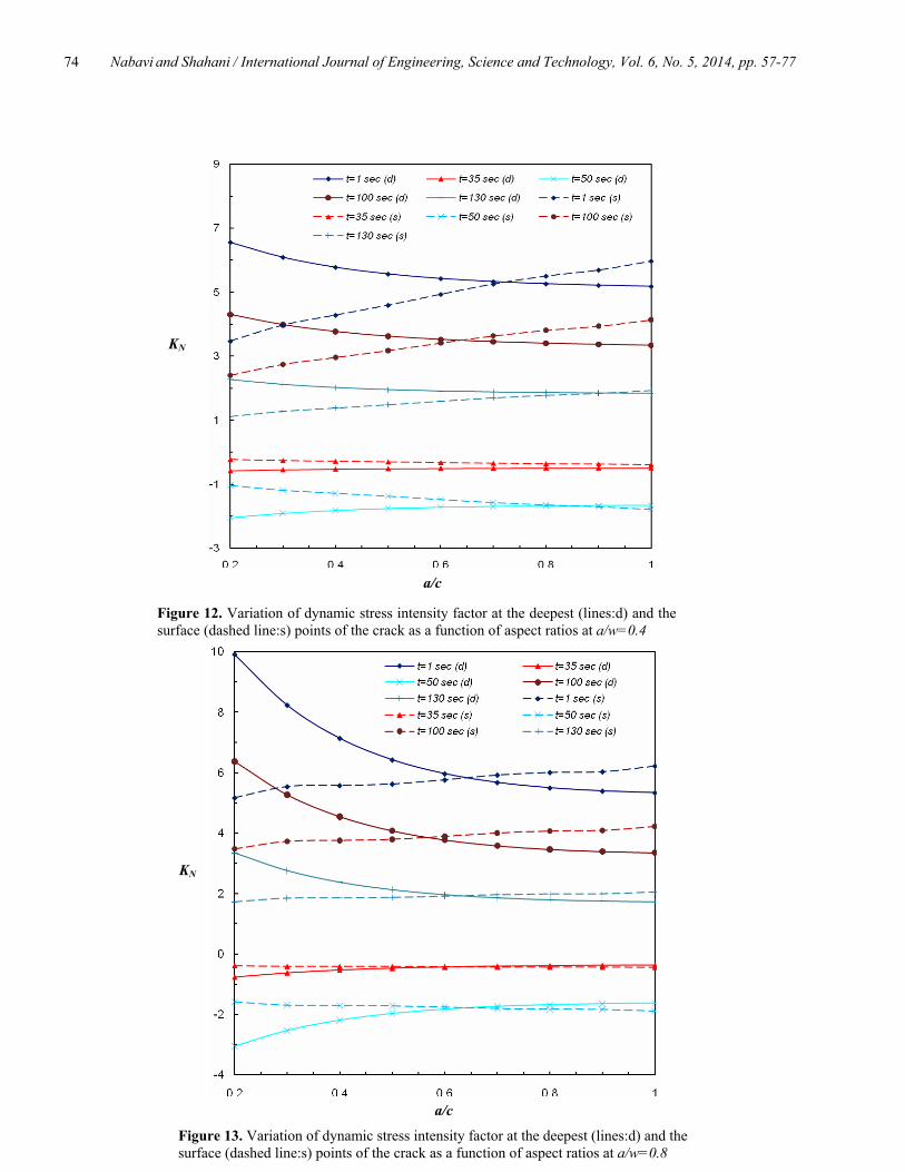
On the other hand, Figures 11-13 show that for small depth cracks (small wa / values as shown in Figure 11) the deepest point of the crack is less sensitive to the variations of the crack aspect ratio in different times. In other words, variations of the aspect ratio of the crack do not affect so much on the stress intensity factor of the deepest point. However, in deep cracks (Figure 13) the surface points are less sensitive to the variations of the aspect ratio in different instants of time.
Another important conclusion can be drawn noting the Figures 11 through 13 which is of practical interest. In narrow cracks (small aspect ratios), the deepest point is the critical point of the stress intensity factor for all relative depths and instants of time and any probable crack propagation starts from the deepest point. For circular cracks )1/( =ca , the surface points always (for all relative depths and at each time) have the maximum stress intensity factor and are the points of any probable crack extension.
When the hoop stress is positive and opening mode happens in the crack, in some crack geometries the critical point on the crack front is displaced from the deepest to the corner points. This phenomenon may be referred to as ‘transition’. The hoop stress oscillates between the compressive and tensile values and as a result when the cylinder is under the negative hoop stress the transition phenomena disappears since both points are in closure mode. Because of oscillating the hoop stress distribution, the transition aspect ratio fluctuates. According to the above-mentioned, it can be found that the boundary surface of the cylinder can reflect the elastic waves, resulting in periodically changing values of the dynamic stress intensity factors.
Table 1. Comparison of non-dimensionalized stress intensity factor at the deepest point using the weight function of the present work and that of Zheng et al. (1995)
present weight function Zheng's weight function a/c
a/t
FEM results W.F. Error W.F. Error
0.2 5.9567 5.9485 0.138 5.8580 1.657 0.4 6.8174 6.8019 0.229 6.6907 1.859 0.6 8.2502 8.2026 0.577 8.0929 1.906
0.2
0.8 10.2967 10.2215 0.731 9.9993 2.888 0.2 5.6897 5.6885 0.022 5.6415 0.847 0.4 5.9845 6.0023 -0.298 5.9552 0.490 0.6 6.4864 6.5139 -0.425 6.5172 -0.476
0.4
0.8 7.2829 7.3435 -0.832 7.2860 -0.043 0.2 5.5494 5.5412 0.148 5.5535 -0.073 0.4 5.6563 5.6415 0.261 5.6256 0.543 0.6 5.8305 5.7871 0.744 5.8052 0.433
0.6
0.8 6.1966 6.1254 1.150 6.0737 1.985 0.2 5.4479 5.4444 0.066 5.5120 -1.175 0.4 5.4814 5.4751 0.115 5.4738 0.138 0.6 5.5086 5.4851 0.427 5.4904 0.330
0.8
0.8 5.6744 5.6371 0.658 5.5689 1.860 0.2 5.3631 5.3700 -0.129 5.4912 -2.389 0.4 5.3661 5.3944 -0.527 5.4053 -0.729 0.6 5.3186 5.3695 -0.957 5.3662 -0.895
1.0
0.8 5.3707 5.4672 -1.796 5.4129 -0.786 Table 2. Comparison of non-dimensionalized stress intensity factor at the surface point using the weight function of the present work and that of Zheng et al. (1995)
present weight function Zheng's weight function a/c a/t FEM results W.F. Error W.F. Error
0.2 3.1076 3.0736 1.092 3.3292 -7.132 0.4 3.6343 3.5954 1.071 3.9002 -7.318 0.6 4.4013 4.3614 0.906 4.9240 -11.877
0.2
0.8 5.3988 5.3541 0.828 6.4128 -18.782
Nabavi and Shahani / International Journal of Engineering, Science and Technology, Vol. 6, No. 5, 2014, pp. 57-77
70
Table 2 (cont’d). Comparison of non-dimensionalized stress intensity factor at the surface point using the weight function of the present work and that of Zheng et al. (1995)
present weight function Zheng's weight function a/c a/t FEM results W.F. Error W.F. Error
0.2 3.9728 3.9717 0.028 4.2381 -6.6774 0.4 4.4348 4.4332 0.035 4.6929 -5.820 0.6 5.0706 5.0754 -0.095 5.4549 -7.579
0.4
0.8 5.7613 5.7735 -0.213 6.5227 -13.216 0.2 4.7538 4.7529 0.019 4.9562 -4.257 0.4 5.1084 5.1065 0.039 5.2170 -2.125 0.6 5.5654 5.5676 -0.038 5.7456 -3.237
0.6
0.8 5.9587 5.9650 -0.106 6.6609 -11.784 0.2 5.3967 5.4244 -0.513 5.5133 -2.161 0.4 5.6646 5.6959 -0.553 5.6577 0.122 0.6 5.9762 6.0191 -0.717 6.0601 -1.404
0.8
0.8 6.1564 6.2163 -0.974 6.8406 -11.114 0.2 5.9464 5.9667 -0.342 6.2156 -4.527 0.4 6.1565 6.1793 -0.370 6.3632 -3.358 0.6 6.3596 6.3918 -0.506 6.6619 -4.753
1.0
0.8 6.3871 6.4334 -0.725 7.1098 -11.314
KN
a/c
Figure 5. Variation of dynamic stress intensity factor at the deepest point of the crack as a function of aspect ratios at t=1 sec
5.1
6.1
7.1
8.1
9.1
0.2 0.3 0.4 0.5 0.6 0.7 0.8 0.9 1
a/w=0.2 a/w=0.4
a/w=0.6 a/w=0.8
Nabavi and Shahani / International Journal of Engineering, Science and Technology, Vol. 6, No. 5, 2014, pp. 57-77
71
KN
a/c
Figure 6. Variation of dynamic stress intensity factor at the surface point of the crack as a function of aspect ratios at t=1 sec
2.9
3.9
4.9
5.9
0.2 0.3 0.4 0.5 0.6 0.7 0.8 0.9 1
a/w=0.2 a/w=0.4
a/w=0.6 a/w=0.8
KN
a/c
Figure 7. Variation of dynamic stress intensity factor at the deepest point of the crack as a function of aspect ratios at t=50 sec
-3.1
-2.6
-2.1
-1.6
0.2 0.3 0.4 0.5 0.6 0.7 0.8 0.9 1
a/w=0.2 a/w=0.4
a/w=0.6 a/w=0.8
Nabavi and Shahani / International Journal of Engineering, Science and Technology, Vol. 6, No. 5, 2014, pp. 57-77
72
KN
a/c
Figure 8. Variation of dynamic stress intensity factor at the surface point of the crack as a function of aspect ratios at t=50 sec
-1.9
-1.7
-1.5
-1.3
-1.1
-0.9
0.2 0.3 0.4 0.5 0.6 0.7 0.8 0.9 1
a/w=0.2 a/w=0.4
a/w=0.6 a/w=0.8
KN
a/c
Figure 9. Variation of dynamic stress intensity factor at the deepest point of the crack as a function of aspect ratios at t=100 sec
3.2
4.2
5.2
6.2
0.2 0.3 0.4 0.5 0.6 0.7 0.8 0.9 1
a/w=0.2 a/w=0.4
a/w=0.6 a/w=0.8
Nabavi and Shahani / International Journal of Engineering, Science and Technology, Vol. 6, No. 5, 2014, pp. 57-77
73
KN
a/c
Figure 10. Variation of dynamic stress intensity factor at the surface point of the crack as a function of aspect ratios at t=100 sec
2
2.5
3
3.5
4
0.2 0.3 0.4 0.5 0.6 0.7 0.8 0.9 1
a/w=0.2 a/w=0.4
a/w=0.6 a/w=0.8
Figure 11. Variation of dynamic stress intensity factor at the deepest (lines:d) and the surface (dashed line:s) points of the crack as a function of aspect ratios at a/w=0.2
KN
a/c
Nabavi and Shahani / International Journal of Engineering, Science and Technology, Vol. 6, No. 5, 2014, pp. 57-77
74
Figure 12. Variation of dynamic stress intensity factor at the deepest (lines:d) and the surface (dashed line:s) points of the crack as a function of aspect ratios at a/w=0.4
KN
a/c
Figure 13. Variation of dynamic stress intensity factor at the deepest (lines:d) and the surface (dashed line:s) points of the crack as a function of aspect ratios at a/w=0.8
KN
a/c
Nabavi and Shahani / International Journal of Engineering, Science and Technology, Vol. 6, No. 5, 2014, pp. 57-77
75
6. Conclusions
The dynamic stress intensity factors are derived for an internal longitudinal semi-elliptical crack in a thick-walled cylinder subjected to transient dynamic stresses. The dynamic elasticity problem in an uncracked thick-walled cylinder under internal transient pressure is solved analytically using the finite Hankel transform. The history and distribution of dynamic stresses in thick-walled cylinders are derived in terms of Bessel series. Then, a three-dimensional finite element method is employed to calculate accurate weight functions for the deepest and the surface points of semi-elliptical surface crack in the cylinder. A useful relation has been derived based on piece-wise curve fitting on the stress from which, the stress intensity factors for both points of the three-dimensional crack have been obtained at each instant of time. Exact analytical solutions for the weight function integral are obtained over discrete intervals, and then summed to compute the dynamic stress intensity factors. The main results of this parametric analysis can be summarized as follows: • Dynamic loading of the cylinder causes a fluctuating behavior of the stress intensity factors at the deepest and the surface
points of the crack. • At some instants of time the deepest and surface points of the crack experience positive stress intensity factors while at some
other instants they lie in closure mode. • The absolute value of the stress intensity factor decreases at the deepest point as the aspect ratio increases in each times and for
all crack relative depths. • The absolute value of the stress intensity factor increases at the surface point with the increase in crack aspect ratio. • The stress intensity factor at the surface point of the crack increases as the crack becomes deeper (greater wa / ) in different
instants of time. • In narrow cracks (small aspect ratios), the deepest point is the critical point of the stress intensity factor for all relative depths
and instants of time and any probable crack propagation starts from the deepest point. • For circular cracks )1/( =ca , the surface point always has the maximum stress intensity factor for all relative depths and at any
time and is the point of any probable crack extension. • The deepest point of small depth cracks is less sensitive to the variations of the crack aspect ratio in different times and
variations of the aspect ratio of the crack do not affect so much on the stress intensity factor of the deepest point. • The surface points of deep cracks are less sensitive to the variations of the aspect ratio in different instants of time.
Nomenclature a crack depth (m) c crack length (m) E elastic modulus of the material (MPa)
0F , 1F boundary correction factors at the surface point H material constant (MPa) K stress intensity factor (Mpa.m1/2)
),( nrK λ kernel of the transformation ),( arm weight function
iP internal pressure (MPa)
oP external pressure(MPa) Q semi-elliptical crack shape factor
iR inner radius of cylinder (m)
oR outer radius of cylinder (m) t time (s) u radial displacement (m)
),( xav crack opening displacement (m) w wall thickness (m)
0Y , 1Y boundary correction factors at the deepest point
nλ the positive roots µ shear modulus of the material (MPa) v Poisson’s ratio
Nabavi and Shahani / International Journal of Engineering, Science and Technology, Vol. 6, No. 5, 2014, pp. 57-77
76
ρ density (kg/m3)
rσ radial stress (MPa)
θσ hoop stress(MPa)
References
Atluri S.N., Kathiresan K. (1979) 3D Analyses of Surface Flaws in Thick-Walled Reactor Pressure-Vessels Using Displacement-Hybrid Finite Element Method. Nuclear Engineering and Design, Vol. 51, pp. 163-176.
ANSYS Release 11, ANSYS, Inc, Canonsburg, PA, 2007. Banks-Sills L. (1991) Application of the finite element to linear elastic fracture mechanic. Applied Mechanic Review 44:447-461. Bueckner H.F. (1970) Novel principle for the computation of stress Intensity Factors. ZAMM - Journal of Applied Mathematics
and Mechanics. Vol. 50, No. 9, pp. 529-546. Chen D.H., Nisitani H., Mori K. (1995) Stress intensity factors for an internal semi-elliptical surface crack in cylindrical pressure
vessels. Journal of Pressure Vessel Technology. Vol. 117, pp. 213-221. Chen A., Liao L., Zhang D. (2009) Analysis of dynamic stress intensity factors of thick-walled cylinder under internal impulsive
pressure. Acta Mechanica Sinica Vol. 25, pp. 803-809 Fett T., Mattheck C., Munz D. (1987) On the calculation of crack opening displacement from the stress intensity factor.
Engineering Fracture Mechanics Vol. 27, pp. 697-715. Glinka G., Shen G. (1991) Universal features of weight functions for cracks in Mode I. Engineering Fracture Mechanics Vol. 40,
pp. 1135-1146. Guozhong C., Kangda Z., Dongdi W. (1995a) Stress intensity factors for semi-elliptical surface cracks in plates and cylindrical
pressure vessels using the hybrid boundary element method. Engineering Fracture Mechanics Vol. 52, pp. 1035-1054. Guozhong C., Kangda Z., Dongdi W. (1995b) Stress Intensity factors for Internal semi-elliptical surface cracks in pressurized
thick-walled cylinders using the hybrid boundary element method. Engineering Fracture Mechanics Vol. 52, pp. 1055-1064. Hachi B.K., Rechak S., Belkacemi Y., Maurice G. (2005) Modelling of elliptical cracks in an infinite body and in a pressurized
cylinder by a hybrid weight function approach. International Journal of Pressure Vessels and Piping Vol. 82, pp. 917-924. Kamaya M., Nishioka T. (2005) Analysis of surface crack in cylinder by finite element alternating method. Journal of Pressure
Vessel Technology Vol. 127, pp. 165-172. Kiciak A., Glinka G., Burns D.J. (2003) Calculation of stress intensity factors and crack opening displacements for cracks
subjected to complex stress fields. Journal of Pressure Vessel Technology Vol. 125, pp. 260-266. Leishear R.A. (2007) Dynamic pipe stresses during water hammer: A finite element approach. Journal of Pressure Vessel
Technology Vol. 129, pp. 226-233. Lin X.B., Smith R.A. (1998) Fatigue growth prediction of internal surface cracks in pressure vessels. Journal of Pressure Vessel
Technology Vol. 120, pp. 17-23. Moftakhar A.A., Glinka G. (1992) Calculation of stress intensity factors by efficient integration of weight functions. Engineering
Fracture Mechanics Vol. 43, pp. 749-756. Newman J.C., Raju I.S. (1980) Stress-intensity Factors for internal surface cracks in cylindrical pressure vessels. Journal of
Pressure Vessel Technology Vol. 102, pp. 342-348. Newman J.C., Raju I.S. (1982) Stress intensity factors for internal and external surface crack in cylindrical vessels. Journal of
Pressure Vessel Technology Vol. 104, pp. 293-298. Okumura I.A. (1989) Stresses in a transversely isotropic, short hollow cylinder subjected to an outer band load. Ingenieur-Archiv
Vol. 59, pp. 310-324. Pook L.P. (1994) Some implications of corner point singularity. Engineering Fracture Mechanics Vol. 48, pp. 367-378. Pook L.P. (2000) Crack profiles and corner point singularities. Fatigue and Fracture of Engineering Materials and Structures Vol. 23, pp. 141-150. Rice J.R. (1972) Some remarks on elastic crack-tip stress fields. International Journal of Solids and Structures Vol. 8, pp. 751–758. Sekine H., Koizumi R. (1982) Stress intensity factors for an embedded crack in a thick walled cylinder subjected to internal
pressure. International Journal of Fracture Vol. 18, pp. R3-R8. Shahani A.R., Nabavi S.M. (2005) Calculation of stress intensity factors for a semi-elliptical crack in a thick-walled cylinder
subjected to thermal loading. In: Proceeding of 13th Annual (International) Mechanical Engineering Conference, Isfahan University of Technology, Isfahan, Iran.
Shahani A.R., Nabavi S.M. (2006) Closed-form stress intensity factors for a semi-elliptical crack in a thick-walled cylinder under thermal stress. International Journal of Fatigue Vol. 28, pp. 926-933.
Shahani A.R., Nabavi S.M. (2007) Transient thermal stress intensity factors for an internal longitudinal semi-elliptical crack in a thick-walled cylinder. Engineering Fracture Mechanics Vol. 74, pp. 2585-2602.
Sheng J. (1965) The response of a thin cylindrical shell to transient surface loading. AIAA Journal Vol. 3, pp. 701-709. Shlyannikov V.N. (2000) Fatigue shape analysis for internal surface flaw in a pressurized hollow cylinder. International Journal of
Pressure Vessels and Piping Vol. 77, pp. 227-234.
Nabavi and Shahani / International Journal of Engineering, Science and Technology, Vol. 6, No. 5, 2014, pp. 57-77
77
Sneddon I.N. (1972) The use of integral transform. Mc-Graw Hill. Spiegel M.R. (1968) Mathematical Handbook of Formulas and Tables. New York: Mc-Graw Hill. Suzuki S. (1988) Stress analysis of the cylinder subjected to arbitrarily distributed axisymmetrical loads. Ingenieur-Archiv Vol. 58,
pp. 97-102. Tan C.L., Fenner R.T. (1980) Stress intensity factors for semi-elliptical surface cracks in pressurized cylinders using the boundary
integral equation method. International Journal of Fracture Vol. 16, pp. 233-245. Timoshenko S.P., Goodier J.N. (1987) Theory of Elasticity. Mc-Graw Hill. Wang X., Gong Y. (1991) A theoretical solution for axially symmetric problems in elastodynamics. Acta Mechanica Sinica Vol. 7,
pp. 275-282. Wang Z.Q. (1995) The calculation of dynamic stress intensity factors for a cracked thick walled cylinder. International Journal of
Fracture Vol. 73, pp. 359-366. Yin X.C., Yue Z.Q. (2002) Transient plane-strain response of multilayered elastic cylinders to axisymmetric impulse. Journal of
Applied Mechanics Vol. 69, pp. 825-835. Zheng X.J., Glinka G., Dubey R. (1995) Calculation of stress intensity factors for semi-elliptical cracks in a thick-wall cylinder.
International Journal of Pressure Vessel and Piping Vol. 62, pp. 249-258. Biographical notes S. M. Nabavi received Ph.D. from Khajeh Nasir University of Technology Tehran, Iran in 2007. He is an Assistant Professor in the Department of Aerospace Engineering, M. U. T. Alborz, Iran. His research interests include fatigue, fracture and structural integrity. A. R. Shahani is a Professor in the Department of Mechanical Engineering, Khajeh Nasir University of Technology Tehran, Iran. He has more than 15 years of experience in teaching and research. His current area of research includes fracture mechanics and the finite element analysis. He has also published more than one hundred research articles in journals and international conferences. Received July 2014 Accepted August 2014 Final acceptance in revised form August 2014