Dynamic Stability Analysis Based on Energy … Stability Analysis Based on Energy-Passivity...
10
Dynamic Stability Analysis Based on Energy-Passivity Considerations CHIEH-TSUNG CHI Department of Electrical Engineering Chienkuo Technology University No. 1, Chieh Shou N. Rd., Changhua City 500, TAIWAN E-mail: [email protected] Abstract: - This study aims at researching the relations between the stability characteristics of an ac contactor and the passivity conditions during power disturbances such as voltage sag. Based on the basic definitions of energy passivity, the stability performance of contactor can be determined by employing the flux linkage versus coil current curve of contactor. On the basis of the governing equations of ac contactor, a digital simulation model is first established. The correctness of the contactor model is verified by comparing the difference of the coil current and the armature displacement between model and contactor. The dynamic stability of contactor can be determined by the energy transferred direction in the electric part or the polarity of the time rate of the change of coil inductance. There are three types of voltage sag are respectively assumed to be the experimental case. Finally, we found that the results which were obtained from simulation tests agree well with those of the theoretical inferences. The identifying rules of the stability of contactor during voltage sag are presented here is valuable for the contactor designer to draft an effective compensation strategy in future so as to improve the momentary performance of contactor. Key-Words: - Dynamic stability, contactor, passivity, energy, voltage sag, model 1 Introduction Contactors are devices that have been widely used in all low voltage apparatus. The number of contactors in use is increasing positively proportional to the development of the industrial control. However, they have been identified as a weak link in many processes during power disturbances such as voltage sags. In other words, they are very sensitive to power disturbances [1], [2]. In case of the short-circuit faults of power system and motor reacceleration, the power disturbances will be produced in power system. Unfortunately, the arising positions of these accidental events are often produced outside the controllable area of system [3]. Voltage Sags have been extensively reported as being one of the worst power quality problems. In particular, they are common in rural areas. The voltage sag is defined as the voltage decreases between 0.1 and 0.9 per unit at the power frequency for duration from half a cycle to 1 minute [4]. In many cases, contactors are operated as a switch in a variety of electrical systems for the purpose of power distribution and control. Let an independent system be equipped with contactor, when the contactor face voltage sag, it may be disconnected due to the magnitude of remaining voltage source is insufficient. Consequently, this phenomenon can lead to costly shutdowns in industrial processes [5]. Influencing factors are relevant to the dynamic behaviour of contactor, Collins and Bridgwood showed that contactor drop out and recovery depends upon the point-on-wave occurrence of the voltage sag as well as duration by using experimental approaches. The contactor transient performance caused by shading rings is also studied as in [3], [5]. As for the effects of power disturbances such as voltage sags on the dynamic behaviours of contactor have also been investigated by several authors [6]-[8]. For example, Pedra et al. presented a contactor model to analyze the dynamic behaviors in terms of the sensitivity CBEMA curves. These curves were obtained by different initial phase angles in which voltage sag occurs. Later, Mohamad et al. aimed at studying the dynamic performance of an ac contactor during voltage sag by merely using their self-defined susceptibility level. They also found the ridethrough capability of the contactor when it was subjected to voltage sags. The characteristic for any type of configuration can be simulated through their self-established contactor WSEAS TRANSACTIONS on CIRCUITS AND SYSTEMS Chieh-Tsung Chi ISSN: 1109-2734 119 Issue 3, Volume 7, Marchl 2008
Transcript of Dynamic Stability Analysis Based on Energy … Stability Analysis Based on Energy-Passivity...

Dynamic Stability Analysis Based on Energy-Passivity Considerations
CHIEH-TSUNG CHIDepartment of Electrical Engineering
Chienkuo Technology UniversityNo. 1, Chieh Shou N. Rd., Changhua City 500, TAIWAN
E-mail: [email protected]
Abstract: - This study aims at researching the relations between the stability characteristics of an accontactor and the passivity conditions during power disturbances such as voltage sag. Based on thebasic definitions of energy passivity, the stability performance of contactor can be determined byemploying the flux linkage versus coil current curve of contactor. On the basis of the governingequations of ac contactor, a digital simulation model is first established. The correctness of thecontactor model is verified by comparing the difference of the coil current and the armaturedisplacement between model and contactor. The dynamic stability of contactor can be determined bythe energy transferred direction in the electric part or the polarity of the time rate of the change of coilinductance. There are three types of voltage sag are respectively assumed to be the experimental case.Finally, we found that the results which were obtained from simulation tests agree well with those ofthe theoretical inferences. The identifying rules of the stability of contactor during voltage sag arepresented here is valuable for the contactor designer to draft an effective compensation strategy infuture so as to improve the momentary performance of contactor.
Key-Words: - Dynamic stability, contactor, passivity, energy, voltage sag, model
1 IntroductionContactors are devices that have been widely usedin all low voltage apparatus. The number ofcontactors in use is increasing positivelyproportional to the development of the industrialcontrol. However, they have been identified as aweak link in many processes during powerdisturbances such as voltage sags. In other words,they are very sensitive to power disturbances [1], [2].In case of the short-circuit faults of power systemand motor reacceleration, the power disturbanceswill be produced in power system. Unfortunately,the arising positions of these accidental events areoften produced outside the controllable area ofsystem [3].
Voltage Sags have been extensively reported asbeing one of the worst power quality problems. Inparticular, they are common in rural areas. Thevoltage sag is defined as the voltage decreasesbetween 0.1 and 0.9 per unit at the power frequencyfor duration from half a cycle to 1 minute [4]. Inmany cases, contactors are operated as a switch in avariety of electrical systems for the purpose ofpower distribution and control. Let an independentsystem be equipped with contactor, when the
contactor face voltage sag, it may be disconnecteddue to the magnitude of remaining voltage source isinsufficient. Consequently, this phenomenon canlead to costly shutdowns in industrial processes [5].
Influencing factors are relevant to the dynamicbehaviour of contactor, Collins and Bridgwoodshowed that contactor drop out and recoverydepends upon the point-on-wave occurrence of thevoltage sag as well as duration by usingexperimental approaches. The contactor transientperformance caused by shading rings is also studiedas in [3], [5]. As for the effects of powerdisturbances such as voltage sags on the dynamicbehaviours of contactor have also been investigatedby several authors [6]-[8]. For example, Pedra et al.presented a contactor model to analyze the dynamicbehaviors in terms of the sensitivity CBEMA curves.These curves were obtained by different initialphase angles in which voltage sag occurs. Later,Mohamad et al. aimed at studying the dynamicperformance of an ac contactor during voltage sagby merely using their self-defined susceptibilitylevel. They also found the ridethrough capability ofthe contactor when it was subjected to voltage sags.The characteristic for any type of configuration canbe simulated through their self-established contactor
WSEAS TRANSACTIONS on CIRCUITS AND SYSTEMS
Chieh-Tsung Chi
ISSN: 1109-2734 119 Issue 3, Volume 7, Marchl 2008
model without having to perform laboratoryexperiments. Furthermore, Isao et al. investigatedthat the sensitivity of the electro-magnetic ofcontactor during voltage sags by means ofexperimental approach. At last, they found thatshallow sags may cause faster trip of contactorcomparing to deep sags in some cases. Additionally,several researchers have also reported that thequantities of sags are produced in the equipmentsuch as induction motor and special designedmachines may be measured [9]-[11]. In the lastdecade, the ridethrough methods of contactor duringvoltage sags have attracted more and more attention[12], [13], [14].
Although much work is related to contactor hasbeen done, for example, the impact betweenmovable contact and fixed contact during closingprocess, the measurement of voltage sag and coilcurrent, and the ridethrough of contactor duringvoltage sags, however, little attention has been paidto study the dynamic stability analysis. Theobjective of this research was to examine the effectsof the voltage sags on the dynamic stability of anAC contactor based on the energy passivity theory.Theoretically, the characteristic of singly excitedcontactor is linear and time-varying device; it willbe viewed as inductor too. Based on a general factthat describes any linear passive time-varying RLCsystem which is made of flux-controlled inductors isalways a stable system [15]. For the purpose ofrealizing that the dynamic stability property ofcontactor, especially voltage sag event occurs, thedynamic stability of contactor is identified in termsof the change of energy in the electrical terminal ofcontactor. The methods reported here could bebeneficial to research attempting to increase thedynamic performance of contactor during powerdisturbances.
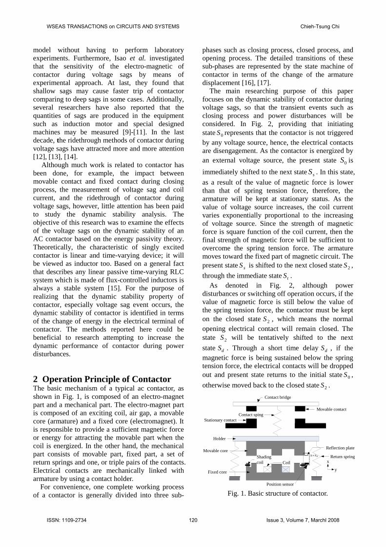
2 Operation Principle of ContactorThe basic mechanism of a typical ac contactor, asshown in Fig. 1, is composed of an electro-magnetpart and a mechanical part. The electro-magnet partis composed of an exciting coil, air gap, a movablecore (armature) and a fixed core (electromagnet). Itis responsible to provide a sufficient magnetic forceor energy for attracting the movable part when thecoil is energized. In the other hand, the mechanicalpart consists of movable part, fixed part, a set ofreturn springs and one, or triple pairs of the contacts.Electrical contacts are mechanically linked witharmature by using a contact holder.
For convenience, one complete working processof a contactor is generally divided into three sub-
phases such as closing process, closed process, andopening process. The detailed transitions of thesesub-phases are represented by the state machine ofcontactor in terms of the change of the armaturedisplacement [16], [17].
The main researching purpose of this paperfocuses on the dynamic stability of contactor duringvoltage sags, so that the transient events such asclosing process and power disturbances will beconsidered. In Fig. 2, providing that initiatingstate 0S represents that the contactor is not triggeredby any voltage source, hence, the electrical contactsare disengagement. As the contactor is energized byan external voltage source, the present state 0S is
immediately shifted to the next state sS . In this state,
as a result of the value of magnetic force is lowerthan that of spring tension force, therefore, thearmature will be kept at stationary status. As thevalue of voltage source increases, the coil currentvaries exponentially proportional to the increasingof voltage source. Since the strength of magneticforce is square function of the coil current, then thefinal strength of magnetic force will be sufficient toovercome the spring tension force. The armaturemoves toward the fixed part of magnetic circuit. Thepresent state sS is shifted to the next closed state 2S ,
through the immediate state tS .As denoted in Fig. 2, although power
disturbances or switching off operation occurs, if thevalue of magnetic force is still below the value ofthe spring tension force, the contactor must be kepton the closed state 2S , which means the normalopening electrical contact will remain closed. Thestate 2S will be tentatively shifted to the next
state dS . Through a short time delay dS , if themagnetic force is being sustained below the springtension force, the electrical contacts will be droppedout and present state returns to the initial state 0S ,
otherwise moved back to the closed state 2S .
Movable contactContact sping
Stationary contact
Holder
Fixed core
Return springCoil
0xxShadingcoil x
y
Position sensor
Reflection plateMovable core
Contact bridge
Fig. 1. Basic structure of contactor.
WSEAS TRANSACTIONS on CIRCUITS AND SYSTEMS Chieh-Tsung Chi
ISSN: 1109-2734 120 Issue 3, Volume 7, Marchl 2008

where the states and relevant symbols as shown inFig. 2 are defined as follows:
0S : initial state, generally indicates the contact isopen,
sS : triggering state; as the coil is energized, and themagnetic force is lower than the spring tensionforce,
tS : attracting state; since the strength of magneticforce is beyond the spring tension force, thearmature moves toward fixed part,
2S : closed state; the cores is maintain in pick-upstate,
dS : suspending state; if the voltage sags or poweroff occurs, the contactor may need respondingtime,
eF : magnetic force,
fF : spring tension force.
In a closed state 2S , if voltage sags or openingprocess occurs, the magnetic force will be reducedgreatly caused by the input electrical energy is lost.The state will be tentatively shifted to the immediatestate dS and even moved back to the initial state ifthere is no additional electrical energy is supplied;otherwise recovers to the closed state, 2S .
S0
S2
Sd
fe FF
fe FF
fe FF
fe FF
fe FF
Ss
St
fe FF
fe FF
Fig. 2. The dynamic behaviour of contactor is shownas dynamic state machine.
3 Dynamic Characteristics AnalysisIn fact, the dynamic behaviors of contactor are anenergy transfer from electrical system to mechanicalsystem. Most of the closure process of contactor; itsproperties are belonging to a linear and time-varyingoperation [18]. The behaviour of contactor can beaccounted for the energy transfer. If it is
mathematically to separate those loss mechanismsfrom the magnetic energy-storage mechanism, thecontactor coupling field can be represented as alossless and conservative magnetic energy-conversion system with the electrical andmechanical terminals, as shown in Fig. 3. In acontactor, this type of system the magnetic energy-conversion system serves as the coupling mediumbetween the electric and mechanical terminals.
Magneticsystem
Electricalsystem
Mechanicalsystem
EW eW mW MW
)(0 actionmotorWm
)(0 actiongeneratorWm
(Lossless & Conservative )
Fig. 3. Energy balance relationship of contactor.According to the principle of conservative of
energy, the stored energy in the lossless magneticenergy-conversion system is neither created nordestroyed; it is merely changed in form. Therefore,in a contactor system, the energy transfers betweenelectrical system and mechanical system can simplybe described as follows:
mef dWdWdW (1)
edW : differential electrical-energy input
fdW : differential change in magnetic stored energy
mdW : differential mechanical-energy outputIf the net mechanical energy or electrical energy
is negative, the behaviour of contactor performs agenerator action; on the contrarily, if the netmechanical energy or electrical energy is positive,the behaviour of contactor performs a motor action.
The total energy transferred to the magnetic fieldfrom electrical system may be expressed as:
dtiedWe (2)
where i is the coil current. By the application ofFaraday’s law, the induced voltage across the coil ofcontactor can be represented in terms of the changeof flux linkagewith respect to time.
dtd
e
(3)
Substituting (3) into (2), we obtain
WSEAS TRANSACTIONS on CIRCUITS AND SYSTEMS Chieh-Tsung Chi
ISSN: 1109-2734 121 Issue 3, Volume 7, Marchl 2008

didWe (4)
By employing the Newton’s law of motion, theenergy output from mechanical system can beexpressed in a differential form as
dxFdW em (5)
Substituting (4) and (5) into (1), the finalrepresentation of differential change in magneticstored energy then becomes
dxFiddW ef (6)
Since the magnetic energy-conversion system islossless, it is a conservative system and the value of
fW is uniquely specified by the values of and x .
Thus, fW is the same independent of howand x
are brought to their final values. It is convenient tofix mathematically the position of the mechanicalsystem associated with the coupling field and thenexcite the electrical system with the displacement ofthe mechanical system held fixed. Equation (1)becomes
iddW f (7)
As shown in Fig. 4, the area to the right of the icurve is called the coenergy and it is expressed
fc WiW (8)
Taking the differentiation of (8) with respect to bothsides, yields
di
ididdWc
)((9)
fW
cW
i
Fig. 4. Stored energy and coenergy in the couplingfield of contactor.
In a closure process of contactor, refer to the basiccontactor structure in the Fig. 1, let us assume thatas the movable part moves from 1xx to 2xx ,
where 12 xx , the i curve moves from point ato point b. Consequently, the change in the fieldenergy is
)()( oadoareaobdoareaW f (10)
Similarly, the change in eW , supposed it is denoted
as eW and given
)( 1bdccaTareaWe (11)
Since the energy relationship between electricalsystem, magnetic energy storage system, andmechanical system has been shown in (1). Hence
)( 1booaTarea
WWW efm
(12)
The change in mW is negative, which representsthe energy is supplied to the mechanical systemfrom the coupling field part of which came from theenergy stored in the field and part from the electricalsystem. The net mW for the cycle from point a to
point b back to point a through 1Tis the shaded area
shown in Fig. 5. Since fW is zero for this cycle
)( 1boToaarea
WW em
(13)
i
0
a
b
c
d1T
1T
1xx
2xx
Fig. 5. Energy conversion of contactor for i patha to b through 1T trace, then back to a through 1T
trace (generator action).
WSEAS TRANSACTIONS on CIRCUITS AND SYSTEMS Chieh-Tsung Chi
ISSN: 1109-2734 122 Issue 3, Volume 7, Marchl 2008

i
0
a
b
c
d
2T2T
1xx
2xx
Fig. 6. Energy conversion of contactor for i patha to b through 2T trace, then back to a through 2T
trace (motor action).For the cycle shown the net eW is negative, thus
mW is positive; we have generator action. Inanother special case, as shown in Fig. 6, assume thatenergy conversion of contactor for i path from ato b through 2T trace, then back to a through 2Ttrace. We found that the cycle shown the net eW is
positive, thus mW is negative; we have motoraction.
4. Passivity and StabilityContactor can be sometimes viewed as a one-port,which includes linear and time-varying elements[14], [19]-[22]. Let us drive this one-port by avoltage source as shown in Fig. 7. According tobasic physics theory, we have known thatinstantaneous power entering the one-port at time tis defined as
)()()( titetp (14)
The energy transferred to the contactor from time 0t
to t is
tdtitetdtpttWt
t
t
t )()()(),(
000 (15)
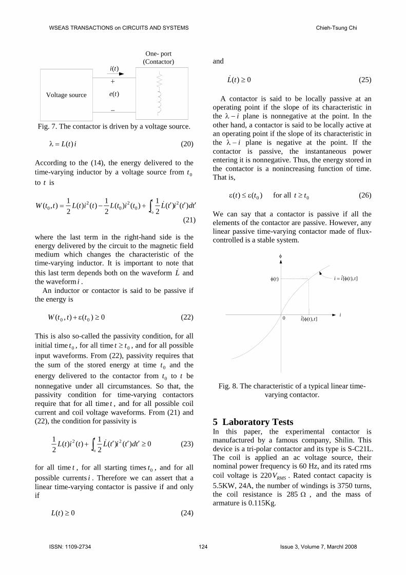
Since the dynamic behaviour of contactors innature are equivalent to a linear and time-varyinginductor. The characteristic is given for each t by acurve similar to that shown in Fig. 8, the curveschanges as t varies. Supposed those at all times tthe characteristic curve goes through the origin; thus,the inductor is in the zero state when the flux is zero.
In addition, we also assume that at all times t theinductor is flux-controlled; therefore, we mayrepresent the linear time-varying inductor by
),(̂ tii (16)
Note that i is an explicit function of both and t .The deduced voltage across the coil has been givenby Faraday’s law as seen in (3). Substitution of (3)and (16) into (15), the energy transferred by thevoltage source to the inductor from time 0t to t canbe written as
)(
)(0
00
),(̂)()(),(t
t
t
tdtitdtitettW (17)
Equation (17) shows that ),( 0 ttW is a function of
the flux at the starting time 0t and at the observingtime t . If we assume that the initiating state of fluxis zero, that is, 0)( 0 t , and if we choose the stateof zero flux to correspond to zero stored energy,then, recalling that an inductor stores energy butdoes not dissipate energy, according to the energyconservation, the energy storedmust be equal tothe energy delivered by the voltage source from 0tto t , that is, ),( 0 ttW , must be equal to the energystored
)(
00 ),(̂),(]),([
tdtittWtt (18)
Note that is only the dummy variable ofintegration and that t is considered as a fixedparameter during the integration process. Equation(18) can also be rewritten in the following form:
t
ttdtt
tttttttW
0
)]),([]),([]),([),( 000
(19)
The first two terms give the difference between theenergy stored at time t and the energy stored at 0t .The third term is the energy delivered by the circuitto the magnetic field medium which changes thecharacteristic of the contactor; thus, it is the workdone by the electrodynamic for forces during thechanges of the configuration of the contactor.
As previously stated, if the input of contactor isassumed as a time-varying inductor, we use a time-varying inductance )(tL to describe its time-varyingcharacteristic. Thus,
WSEAS TRANSACTIONS on CIRCUITS AND SYSTEMS Chieh-Tsung Chi
ISSN: 1109-2734 123 Issue 3, Volume 7, Marchl 2008
Voltage source
)(ti
)(te
One- port(Contactor)
Fig. 7. The contactor is driven by a voltage source.
itL )( (20)
According to the (14), the energy delivered to thetime-varying inductor by a voltage source from 0tto t is
tdtitLtitLtitLttWt
t )()(
2
1)()(
2
1)()(
2
1),( 2
02
02
00
(21)
where the last term in the right-hand side is theenergy delivered by the circuit to the magnetic fieldmedium which changes the characteristic of thetime-varying inductor. It is important to note thatthis last term depends both on the waveform Landthe waveform i .
An inductor or contactor is said to be passive ifthe energy is
0)(),( 00 tttW (22)
This is also so-called the passivity condition, for allinitial time 0t , for all time 0tt , and for all possibleinput waveforms. From (22), passivity requires thatthe sum of the stored energy at time 0t and the
energy delivered to the contactor from 0t to t benonnegative under all circumstances. So that, thepassivity condition for time-varying contactorsrequire that for all time t , and for all possible coilcurrent and coil voltage waveforms. From (21) and(22), the condition for passivity is
0)()(21
)()(21 22
0
tdtitLtitLt
t (23)
for all time t , for all starting times 0t , and for allpossible currents i . Therefore we can assert that alinear time-varying contactor is passive if and onlyif
0)( tL (24)
and
0)( tL (25)
A contactor is said to be locally passive at anoperating point if the slope of its characteristic inthe i plane is nonnegative at the point. In theother hand, a contactor is said to be locally active atan operating point if the slope of its characteristic inthe i plane is negative at the point. If thecontactor is passive, the instantaneous powerentering it is nonnegative. Thus, the energy stored inthe contactor is a nonincreasing function of time.That is,
)()( 0tt for all 0tt (26)
We can say that a contactor is passive if all theelements of the contactor are passive. However, anylinear passive time-varying contactor made of flux-controlled is a stable system.
i
0 ]),([̂ tti
)(t ]),([̂ ttii
Fig. 8. The characteristic of a typical linear time-varying contactor.
5 Laboratory TestsIn this paper, the experimental contactor ismanufactured by a famous company, Shilin. Thisdevice is a tri-polar contactor and its type is S-C21L.The coil is applied an ac voltage source, theirnominal power frequency is 60 Hz, and its rated rmscoil voltage is 220 RMSV . Rated contact capacity is5.5KW, 24A, the number of windings is 3750 turns,the coil resistance is 285 , and the mass ofarmature is 0.115Kg.
WSEAS TRANSACTIONS on CIRCUITS AND SYSTEMS Chieh-Tsung Chi
ISSN: 1109-2734 124 Issue 3, Volume 7, Marchl 2008

5.1 Establishing Simulation ModelAs previous statement, we have known that thegoverning equations of contactor are basicallycomposed by the electrical circuit equations andmechanical motion equations. At first, these fiveindividual simulation sub-modules corresponding toeach governing equation are established. In addition,a complete contactor simulation model is built bymeans of combining with five sub-modules. Theobtained contactor simulation model is as shown inFig. 9.
Voltage equ.
e
i
u
fai fai
x
Flux linkage equ.
i
x
v
e
dL/dx
Emf equ.
Magnetic force equ.
dL/dx
i
Fe Fe
x
v
Mechanical equ.
i
[t1,E]
Input voltage
Fig. 9. Simulation model of contactor is establishedby the Matlab/Simulink software.
0 0.02 0.04 0.06 0.08 0.1 0.12 0.14 0.16 0.18 0.2-0.4
-0.2
0
0.2
0.4
0.6
0.8
1simulationexperiment
Coi
lcur
rent
(A)
Time (sec)
(a)
0 0.02 0.04 0.06 0.08 0.1 0.12 0.14 0.16 0.18 0.20
1
2
3
4
5
6
7x10⁻³
simulationexperiment
Arm
atur
epo
sitio
n(m
m)
Time (sec)
(d)Fig. 10. Parameters comparison between simulation
model and real contactor (a) coil current (b)armature displacement.
However, the comparisons of the correspondingparameters between the experimental results and the
simulation results are essential to verify thecorrectness of the developed contactor simulationmodel. In Fig. 10, it is shown that the simulationresults such as coil current and armaturedisplacement using contactor model are basically inagreement with well the experimental results. Thisresult stands for the accuracy of contactor model isacceptable and its behaviour can be equivalent to thebehaviour of contactor.
5.2 Flux Linkage versus Coil CurrentVarying Curves
In theory, the characteristics of the contactor can befeatured with its input driving-point impedance. Asmentioned above, when the inductive one-port ispassive, the instantaneous power entering it isnonnegative. Thus, the energy stored in the systemis going to be a nonincreasing function of time, asseen in (26). However, any linear passive time-varying system made of flux-controlled inductors isa stable system. We can say that a system is passiveif all the elements of the system are passive.Therefore, we say that the dynamic behaviour ofcontactors in the period of voltage sags is eitherstable or unstable can be completely determined bythe net energy stored in the contactor. If the netenergy stored is nonincreasing, the dynamic stabilityof contactor will be said at stable state. As shown inFig. 11(b), the i curves in the closing and closedprocesses are all linear, they agree well with thetheoretical analysis.
In many applications, most of the characteristic ofcontactor is passive, but sometimes exists locallyactive at some operating points. Some part ofthe i curve, the slope of the characteristic ofcontactor is negative. This phenomenon representsthat the energy transfer is from the mechanicalsystem to electrical system. The dynamic behaviourcan appear momentarily unstable. Eitherengagement or disengagement of the electricalcontacts is determined by the energy transferreddirection or the polarity of )(),( 00 tttW from theelectrical system to the magnetic energy-conversionsystem. As mentioned above, the dynamiccharacteristic of contactor can be viewed as a lineartime-varying inductor. However, in case of a lineartime-varying inductor to be passive, itscharacteristic (in the i plane) must pass throughthe origin and lies in the first and third quadrants inthe neighbourhood of the origin. Also, if thecharacteristic of a linear time-varying inductor ismonotonically increasing and lies in the first andthird quadrants, then it is passive.
WSEAS TRANSACTIONS on CIRCUITS AND SYSTEMS Chieh-Tsung Chi
ISSN: 1109-2734 125 Issue 3, Volume 7, Marchl 2008

0 0.2 0.4 0.6 0.8 1 1.2 1.4 1.6 1.80
1
2
3
4
5
6
7x 10
-3
Arm
atur
epo
sitio
n(m
)
Time (sec)
(a)
-1.5 -1 -0.5 0 0.5 1 1.5-1.5
-1
-0.5
0
0.5
1
Lam
da(H
-A)
Coil current (A)
Closing process
Closed process
(b)Fig. 11. When the voltage sag occurs with a
magnitude 10%, duration one cycles, and point-in-
wave 45 , the varying curves are the coilinductance )(tL and position.
1.58 1.6 1.62 1.64 1.66 1.68 1.7 1.72 1.74
4.5
5
5.5
6
6.5
x 10-3
decreasingincreasing
Arm
atur
epo
sitio
n(m
)
Time (sec)
(a)
-0.4 -0.2 0 0.2 0.4 0.6 0.8 1 1.2
-0.2
-0.15
-0.1
-0.05
0
0.05
0.1
0.15
0.2
0.25
Coil current (A)
Lam
da(H
-A)
0)( tL
decreasingincreasing
(b)Fig. 12. When the voltage sag occurs with a
magnitude 10%, duration one cycle and point-in-
wave 90 , the varying curves are the coilinductance )(tL and position.
1.35 1.4 1.45 1.5 1.55 1.6 1.65 1.7 1.75
0
1
2
3
4
5
6
x 10-3
Time (sec)
Arm
atur
epo
sitio
n(m
)
decreasingincreasing
(a)
-0.4 -0.2 0 0.2 0.4 0.6 0.8 1-0.4
-0.3
-0.2
-0.1
0
0.1
0.2
0.3
0.4
Coil current (A)
Lam
da(H
-A)
decreasingincreasing
0)( tL
(b)Fig. 13. When the voltage sag occurs with a
magnitude 20%, duration two cycles, and point-in-
wave 90 , the varying curves are of the coilinductance )(tL and position.
WSEAS TRANSACTIONS on CIRCUITS AND SYSTEMS Chieh-Tsung Chi
ISSN: 1109-2734 126 Issue 3, Volume 7, Marchl 2008
As shown in Fig. 11 depicts when the operationof contactor is transferred from closing process toclosed process, there is no power disturbances occur.Since there is no energy change in the electricalsystem, we could say no impact of voltage sagsupon the contactor. Fig. 11 shows that the energystored in the contactor is zero due to no voltage sagoccurs. The armature never leaves away theelectromagnet. Moreover, the i curve ismonotonically increasing and lies in the first andthird quadrants, thus, it is passive. Therefore, theelectrical contacts are kept in the closed state.
If the energy transferred direction in electricalterminal has been changed, as denoted in Fig. 12(b)shows 0L , but its total energy change is stillsuffice for the passive condition as shown in (26).Therefore, although the armature has beendisengaged and re-engaged with the fixed part ofmagnetic circuit, the electrical contacts have nothingaffected the closed state. Fig. 12 shows the totalenergy stored within the disengagement process is -0.02547 joules, while the total energy stored withinre-engaging process is 0.03644 joules duringvoltage sags. In addition, the i curve ismonotonically increasing and lies in the first andthird quadrants as well, therefore, it is passive. Notethat there is a fraction of the characteristic occursthe coil inductance )(tL is negative, as shown in Fig.12(a). As the stated passivity conditions, as seen in(23) to (26), the operating features in some specialtime instants appear locally active. Consequently,the energy stored in the contactor during voltagesags becomes negative and the magnetic circuitdisengage and then re-engage without affecting theengagement of electrical contacts. Nevertheless,from the net energy stored in the contactor point ofview, the contactor is still to be passive and stable.
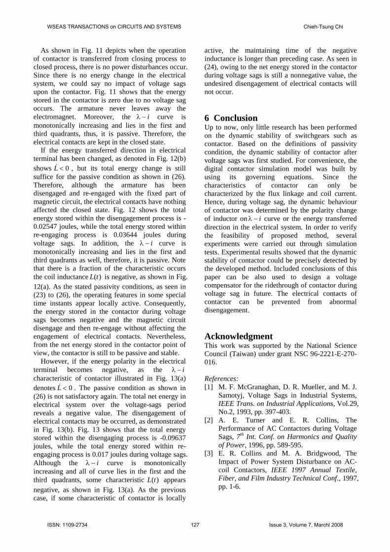
However, if the energy polarity in the electricalterminal becomes negative, as the icharacteristic of contactor illustrated in Fig. 13(a)denotes 0L . The passive condition as shown in(26) is not satisfactory again. The total net energy inelectrical system over the voltage-sags periodreveals a negative value. The disengagement ofelectrical contacts may be occurred, as demonstratedin Fig. 13(b). Fig. 13 shows that the total energystored within the disengaging process is -0.09637joules, while the total energy stored within re-engaging process is 0.017 joules during voltage sags.Although the i curve is monotonicallyincreasing and all of curve lies in the first and thethird quadrants, some characteristic )(tL appearsnegative, as shown in Fig. 13(a). As the previouscase, if some characteristic of contactor is locally
active, the maintaining time of the negativeinductance is longer than preceding case. As seen in(24), owing to the net energy stored in the contactorduring voltage sags is still a nonnegative value, theundesired disengagement of electrical contacts willnot occur.
6 ConclusionUp to now, only little research has been performedon the dynamic stability of switchgears such ascontactor. Based on the definitions of passivitycondition, the dynamic stability of contactor aftervoltage sags was first studied. For convenience, thedigital contactor simulation model was built byusing its governing equations. Since thecharacteristics of contactor can only becharacterized by the flux linkage and coil current.Hence, during voltage sag, the dynamic behaviourof contactor was determined by the polarity changeof inductor on i curve or the energy transferreddirection in the electrical system. In order to verifythe feasibility of proposed method, severalexperiments were carried out through simulationtests. Experimental results showed that the dynamicstability of contactor could be precisely detected bythe developed method. Included conclusions of thispaper can be also used to design a voltagecompensator for the ridethrough of contactor duringvoltage sag in future. The electrical contacts ofcontactor can be prevented from abnormaldisengagement.
AcknowledgmentThis work was supported by the National ScienceCouncil (Taiwan) under grant NSC 96-2221-E-270-016.
References:[1] M. F. McGranaghan, D. R. Mueller, and M. J.
Samotyj, Voltage Sags in Industrial Systems,IEEE Trans. on Industrial Applications, Vol.29,No.2, 1993, pp. 397-403.
[2] A. E. Turner and E. R. Collins, ThePerformance of AC Contactors during VoltageSags, 7th Int. Conf. on Harmonics and Qualityof Power, 1996, pp. 589-595.
[3] E. R. Collins and M. A. Bridgwood, TheImpact of Power System Disturbance on AC-coil Contactors, IEEE 1997 Annual Textile,Fiber, and Film Industry Technical Conf., 1997,pp. 1-6.
WSEAS TRANSACTIONS on CIRCUITS AND SYSTEMS Chieh-Tsung Chi
ISSN: 1109-2734 127 Issue 3, Volume 7, Marchl 2008

[4] R. C. Dugan, M. F. McGranaghan, and H. W.Beaty, Electrical Power System Quality, NewYork, McGraw-Hill, 1996.
[5] E. R. Collins and F. Zapardiel, AnExperimental Assessment of AC ContactorBehavior during Voltage Sags, in Proc. of theIEEE Int. Symposium on Industrial Electronics,Vol.2, 1997, pp. 439 –444.
[6] J. Pedra, F. Corcoles, and L. Sainz, Study ofAC Contactors during Voltage Sags, The 10thInt. Conf. on Harmonics and Quality of Power,Vol.2, 2002, pp. 565 –570.
[7] H. Mohamad and K. M. Nor, Evaluation onSensitivity of AC Contactor during VoltageSag, TENCON 2004, 2004, pp. 295 –298.
[8] I. Isao, H. Masaya, S. Nobuyuki, P.Sompathana, O. Kenji, and I.T oshifumi, Affectof Voltage Sags on Electro-Magnetic Contactor,The 9th Int. Conf. on Electrical Power Qualityand Utilisation, 2007, pp. 1 –6.
[9] V. J. Gosbell, V. Smith, D. A. Robinson, B. S.P. Perera, and R. Coulter, Sag Testing of DairyFarm Milking Equipment, Int. Conf. on PowerSystem Technology, Vol.2, 2000, pp. 947 –952.
[10] J. C. Gomez, M. M. Morcos, C. A. Reineri, andG. N. Campetelli, Behavior of Induction Motordue to Voltage Sags and Short Interruptions,IEEE Trans. on Power Delivery, Vol.17, 2002,pp. 434 –440.
[11] J. Horak, Power Quality: Measurements ofSags and Interruptions, PES TD 2005/2006, pp.733 –739.
[12] A. Kelley, J. Cavaroc, J. Ledford, and L.Vassalli, Voltage Regulator for ContactorRidethrough, IEEE Trans. on IndustryApplications, Vol.36, 2000, pp. 697 –704.
[13] P. Andrada, G. Navarro, and J. I. Perat, A NewPower Supply System for AC Contactor Ride-through, 9th Int. Conf. on Electrical PowerQuality and Utilisation, 2007, pp. 1 –5.
[14] F. A. Guillermo, A. R. Jose, D. M. Basilio, andF. G. Jose-Job, Preservation of Robustness,non-Fragility and Passivity for ControllersUsing Linear Fractional Transformations,WSEAS Trans. on Circuits and Systems, Vol.5,May. 2006, pp. 603-610.
[15] A. D. Charles and S. K. Ernest, Basic CircuitTheory, Taiwan, Central Book Company, 1979.
[16] S. Fang and H. Y. Lin, Magnetic Field Analysisand Control Circuit Design of PermanentMagnet Actuator for AC Contactor, in Proc. 8th
Int. Conf. on Electrical Machines and Systems,2005, pp. 280 –283.
[17] C. T. Chi, A Study of Closing Adaptive Controlin Electronically Controlled IntelligentContactor, TENCON 2006, IEEE Region 10Conf., 2006, pp. 1 –4.
[18] H. Liang, G. C. Ma, L. Cai, X. Yong, and G.. Q.Xie, Research on the Relationship betweenContact Breakaway Initial Velocity and ArcDuration, in Proc. 49th IEEE Holm Conf. onElectrical Contacts, 2003, pp. 204-210.
[19] S. Washizu, T. Ichikawa, K. Yukita, K. M. Y.Got, and, K. Ichiyanagi, Estimation of ATCfrom Viewpoint of Voltage Stability in Multi-Machine Power System, WSEAS Trans. onPower Systems, Vol.1, 2006, pp. 331-340.
[20] F. A. Guillermo, A. R. Jose, and F. G. Jose-Job,Properties of Fractional-Order Linear Systems:Stability and Passivity, WSEAS Trans. onCircuits and Systems, Vol.6, May 2007, pp. 459-464.
[21] Q. Licer, N. E. Alarm, and M. Mrabi, Passivityand Energy based Control for Finding OptimalCompass Gaits, WSEAS Trans. on Systems,Vol.5, Sep. 2006, pp. 2061-2067.
[22] T. T. J.C. and D. M. M.A., EquivalenceBetween Adaptive Passivity Based Control andModel Reference Adaptive Control, WSEASTrans. on Circuits and Systems, Vol.3, Nov.2004, pp. 1912-1917.
WSEAS TRANSACTIONS on CIRCUITS AND SYSTEMS Chieh-Tsung Chi
ISSN: 1109-2734 128 Issue 3, Volume 7, Marchl 2008