Dynamic Analysis of Fluid Power Drive-trains for Variable Speed Wind Turbines

Improving landfill monitoring programswith the aid of geoelectrical - imaging techniquesand geographical information systems Master’s Thesis in the Master Degree Programme, Civil Engineering
KEVIN HINE
Department of Civil and Environmental Engineering Division of GeoEngineering Engineering Geology Research GroupCHALMERS UNIVERSITY OF TECHNOLOGYGöteborg, Sweden 2005Master’s Thesis 2005:22
Dynamic Protocol Analysis Tool forTrainsMaster of Science Thesis in the Programme Computer Science -Networks and Distributed Systems
Rickard GustafssonJimmie Hogklint
Chalmers University of TechnologyUniversity of GothenburgDepartment of Computer Science and EngineeringGoteborg, Sweden, August 2011

The Author grants to Chalmers University of Technology and University of Gothen-burg the non-exclusive right to publish the Work electronically and in a non-commercialpurpose make it accessible on the Internet. The Author warrants that he/she is theauthor to the Work, and warrants that the Work does not contain text, pictures or othermaterial that violates copyright law.
The Author shall, when transferring the rights of the Work to a third party (for examplea publisher or a company), acknowledge the third party about this agreement. If theAuthor has signed a copyright agreement with a third party regarding the Work, theAuthor warrants hereby that he/she has obtained any necessary permission from thisthird party to let Chalmers University of Technology and University of Gothenburg storethe Work electronically and make it accessible on the Internet.
Dynamic Protocol Analysis Tool for Trains
Rickard GustafssonJimmie Hogklint
c© Rickard Gustafsson, August 2011.c© Jimmie Hogklint, August 2011.
Examiner: Arne Linde
Chalmers University of TechnologyUniversity of GothenburgDepartment of Computer Science and EngineeringSE-412 96 GoteborgSwedenTelephone + 46 (0)31-772 1000
Department of Computer Science and EngineeringGoteborg, Sweden August 2011

Abstract
Bombardier is in the process of developing a new solution for controlling trains whichact autonomously. The central unit, Train Control Center(TCC), controls the vehiclesvia TCP/IP. When developing such as system a great amount of time has to be reservedfor testing the product. When testing the vehicle software the TCC is unfit to performand repeat desired test cases. A TCC simulator, TCCSim, was developed instead. Thesimulator will also be helpful in the beginning of the development phase were nothingto test against exists. TCCSim is able to dynamically define messages which can becomposed and sent to the vehicle as well as inject faults into the messages. The vehicleresponse is logged and can be analysed. Test cases are easily reperformed with the abilityto script the behaviour of TCCSim.


Sammanfattning
Bombardier ar i utvecklingsfasen av en ny losning for att kontrollera tag som agerarautonomt. Den centrala enheten, Train Control Center(TCC), kontrollerar fordonen viaTCP/IP. Nar ett sadant system utvecklas maste mycket tid laggas pa att testa systemet.Nar tester gallande mjukvaran i fordonen utfors lampar sig inte TCC att utfora dessaoch aterskapa testfallen. Istallet utvecklades en TCC-simulator, TCCSim. Simulatorn araven praktisk i borjan av utvecklingsfasen da det inte existerar nagonting annat att testamot. TCCSim ar kapabel att dynamiskt definiera meddelanden som kan bli sammansattaoch skickade till fordornet. I meddelandena kan aven fel injiceras. Fordornets svarloggas och kan bli analyserat. Testfall ar latta att aterskapa med mojligheten att skriptaTCCSims beteende.


Acknowledgements
We would like to thank our supervisor and examiner at Chalmers University of Tech-nology, Arne Linde, and our supervisors at Bombardier Transportations, Lars Antbackand Jan Kiessling, for all the help and feedback provided throughout the project. Wewould also like to thank Bo Hermansson at Bombardier Transportation for providingan Com-to-IP converter, making it possible for us to test our product with the old testsystem.
Rickard Gustafsson and Jimmie Hogklint, Gothenburg 11/08/01


Contents
1 Introduction 11.1 Description of Task . . . . . . . . . . . . . . . . . . . . . . . . . . . . . . . 11.2 Project Goals . . . . . . . . . . . . . . . . . . . . . . . . . . . . . . . . . . 2
2 Tools and Specification 32.1 XML - eXtensible Markup Language . . . . . . . . . . . . . . . . . . . . . 32.2 C# . . . . . . . . . . . . . . . . . . . . . . . . . . . . . . . . . . . . . . . . 32.3 MVC/Events . . . . . . . . . . . . . . . . . . . . . . . . . . . . . . . . . . 42.4 IronPython . . . . . . . . . . . . . . . . . . . . . . . . . . . . . . . . . . . 42.5 LINQ . . . . . . . . . . . . . . . . . . . . . . . . . . . . . . . . . . . . . . 42.6 Application . . . . . . . . . . . . . . . . . . . . . . . . . . . . . . . . . . . 42.7 Application Protocol . . . . . . . . . . . . . . . . . . . . . . . . . . . . . . 5
3 TCCSim 73.1 System Overview . . . . . . . . . . . . . . . . . . . . . . . . . . . . . . . . 73.2 TCCSim’s Main View . . . . . . . . . . . . . . . . . . . . . . . . . . . . . 8
3.2.1 Transfer Log . . . . . . . . . . . . . . . . . . . . . . . . . . . . . . 93.2.2 Display information . . . . . . . . . . . . . . . . . . . . . . . . . . 10
3.3 Dynamic Messages . . . . . . . . . . . . . . . . . . . . . . . . . . . . . . . 103.3.1 Message payload structure . . . . . . . . . . . . . . . . . . . . . . . 113.3.2 Creating/Defining Messages . . . . . . . . . . . . . . . . . . . . . . 113.3.3 View Messages . . . . . . . . . . . . . . . . . . . . . . . . . . . . . 15
3.4 Communication Module . . . . . . . . . . . . . . . . . . . . . . . . . . . . 163.4.1 Regarding the protocol . . . . . . . . . . . . . . . . . . . . . . . . . 163.4.2 Stand-alone Module . . . . . . . . . . . . . . . . . . . . . . . . . . 173.4.3 Safety Layer . . . . . . . . . . . . . . . . . . . . . . . . . . . . . . 183.4.4 Work Flow . . . . . . . . . . . . . . . . . . . . . . . . . . . . . . . 19
3.5 Fault Injection . . . . . . . . . . . . . . . . . . . . . . . . . . . . . . . . . 203.5.1 Safety Header . . . . . . . . . . . . . . . . . . . . . . . . . . . . . . 20
i

CONTENTS
3.5.2 Erroneous messages . . . . . . . . . . . . . . . . . . . . . . . . . . 213.6 Script . . . . . . . . . . . . . . . . . . . . . . . . . . . . . . . . . . . . . . 21
3.6.1 Overall Structure . . . . . . . . . . . . . . . . . . . . . . . . . . . . 213.6.2 Script Functionality . . . . . . . . . . . . . . . . . . . . . . . . . . 223.6.3 Print . . . . . . . . . . . . . . . . . . . . . . . . . . . . . . . . . . . 22
4 Design Choices 244.1 User Interface . . . . . . . . . . . . . . . . . . . . . . . . . . . . . . . . . . 24
4.1.1 Message creation . . . . . . . . . . . . . . . . . . . . . . . . . . . . 244.2 Dynamic Messages . . . . . . . . . . . . . . . . . . . . . . . . . . . . . . . 25
4.2.1 Identification by name . . . . . . . . . . . . . . . . . . . . . . . . . 254.2.2 Data types . . . . . . . . . . . . . . . . . . . . . . . . . . . . . . . 26
4.3 Communication Module . . . . . . . . . . . . . . . . . . . . . . . . . . . . 264.4 Fault Injection . . . . . . . . . . . . . . . . . . . . . . . . . . . . . . . . . 27
4.4.1 Erroneous messages . . . . . . . . . . . . . . . . . . . . . . . . . . 274.5 Script . . . . . . . . . . . . . . . . . . . . . . . . . . . . . . . . . . . . . . 28
5 Testing 295.1 White Box Testing . . . . . . . . . . . . . . . . . . . . . . . . . . . . . . . 29
5.1.1 Parameterized Unit Tests . . . . . . . . . . . . . . . . . . . . . . . 295.2 Black Box Testing . . . . . . . . . . . . . . . . . . . . . . . . . . . . . . . 305.3 Test Results . . . . . . . . . . . . . . . . . . . . . . . . . . . . . . . . . . . 30
5.3.1 White Box . . . . . . . . . . . . . . . . . . . . . . . . . . . . . . . 305.3.2 Pex . . . . . . . . . . . . . . . . . . . . . . . . . . . . . . . . . . . 305.3.3 Black Box . . . . . . . . . . . . . . . . . . . . . . . . . . . . . . . . 30
6 Results 32
7 Future Development 347.1 Remote . . . . . . . . . . . . . . . . . . . . . . . . . . . . . . . . . . . . . 347.2 More Than One Vehicle . . . . . . . . . . . . . . . . . . . . . . . . . . . . 34
8 Conclusion 35
9 Discussion 36
References 38
A UML 39
ii

List of Abbreviations
BCC Block Check Code
CRC Cyclic Redundancy Check
DLL Dynamic-Link Library
GUI Graphical User Interface
IP Internet Protocol
LINQ Language INtegrated Query
PInvoke Platform Invocation Services
STDOUT Standard output, text presented from console application
TCC Train Control Center
TCCSim Train Control Center Simulator
TCP Transmission Control Protocol
iii

1
Introduction
Bombardier is a cutting edge company[1] in the field of transportation with trains andairplanes. One area is autonomous train control. In the process of developing theirproduct for simultaneously controlling trains a significant amount of time has to be puton testing the products. This is to make sure the product executes in a safe mannerbecause of the high safety standards regarding trains in general. It is unpractical toperform all these test cases with the actual product thus a simulator can be of help toease the process.
The central system, called Train Control Center(TCC), is controlling the vehicles andthe communication is today via radio link, using serial communication. For testing anddevelopment purposes there exists a simulator software. The serial communication isbeing exchanged with TCP/IP, which means that the central system simulator has to beupdated as well. The existing simulator is incomplete and lacks application handinesswhich means that developing a new simulator is the best option at this point.
1.1 Description of Task
The task for this project is to produce the TCC simulator, TCCSim. Apart from thehigh level goals that can be found in Bombardier’s project description, the process ofdeveloping the simulator includes full specification and implementation.
The purpose of the simulation software is to assist the development and verification of
1

1.2. PROJECT GOALS CHAPTER 1. INTRODUCTION
TCC
Figure 1.1: TCC and trains communicating
the vehicle software and the communication protocol used between the TCC and thevehicles.
1.2 Project Goals
The main interface should provide the main functionality such as sending messages, seemessage exchanges between TCCSim and the vehicle and closer analysing of receivedand sent messages. This will be presented in a structured and reviewable manner.
There should be an interface which makes it easy to handle and create new messages.It should provide the possibility to save these messages as a file which makes them easyto reuse and transfer between computers. It should be possible to create and send newmessages without saving them. The interface has to be intuitive and allow fast and easyinput of data for different message types.
This project uses TCP/IP to communicate with a vehicle. Since this might change inthe future, the communication module should be easily exchangeable.
To truly test the robustness of the protocol and the vehicle software, faults has to be in-jected into the messages sent from TCCSim. There should be circumstantial possibilitiesto put these areas under test by injecting faults.
By implementing scripting ability into the application even more extensible test casescan be performed. The goal is to let a user of TCCSim easily write scripts which can beloaded and executed. The abilities of the script should be the same as the rest of theapplication.
2

2
Tools and Specification
2.1 XML - eXtensible Markup Language
XML[2] is convenient when storing a moderate amount of data. It handles versatileand complex data structures with ease and it is easy for both humans and computersto understand and manipulate the content. The XML files are also easily transferedbetween computers.
2.2 C#
The environment the application is to operate in is the Microsoft Windows platform.Since Microsoft supplies a very good development environment for Windows in VisualStudio this is the natural choice for quick and easy development. Some language sup-ported by Visual Studio has to be chosen. C# is an obvious candidate since it wasdeveloped with XML in mind[3]. The integration of XML in C#’s standard librariesmakes it effortless and transparent working with XML-formated data. The fact that C#also has automatic memory management[4] and is type secure[5] helps the developmentprocess. C# is designed by Microsoft based on development of object oriented applica-tions for Microsoft Windows using the .NET framework, this gives a language that isuncluttered and with strong integration to that API.
3

2.3. MVC/EVENTS CHAPTER 2. TOOLS AND SPECIFICATION
2.3 MVC/Events
To get a good structure and maintainability of the code the design pattern Model-View-Controller(MVC) is used. It divides the different parts of the program in a reusableand a reviewable manner. Since C# is used, delegates and events can be used to passinformation around the application in a MVC type fashion. Each event has an objectattached which contains information regarding the type of event. This object inheritsthe existing class EventArgs. Since C# has co- and contra-variant type system the eventhandlers takes an object of type EventArgs as input but is then able to convert to a morenarrow type. This way one event handler can handle many different type of events bychecking the actual type of the incoming object.
2.4 IronPython
To enable scripting abilities to the application a second programming language has tobe chosen and embedded into the C# code. IronPython[6] is a good fit for this. It isa Python implementation in the .NET platform which makes IronPython very easy tointegrate into the application. All implemented Python features, the .NET libraries aswell as TCCSim’s functionality will be at the user’s disposal writing the script.
2.5 LINQ
LINQ, Language INtegrated Query, was released with version 3.5 of the .NET Frame-work. With LINQ the programmer gets a SQL-query like interface to both in memorydata and relational databases. The in memory data that can be accessed is arrays, lists,XML and data sets[7]. LINQ gives an uniform method to access unordered data thatis transparent, not regarding which kind of data that is to be accessed. This is a verypowerful tool that makes programs easy to maintain because only small changes has tobe done to change the whole data source of the program.
2.6 Application
In the development of this new autonomous system both the stationary and trainbornesubsystems have to be developed at the same time since the transportation medium isbeing exchanged. Both parts are dependent on each other to verify the functionality of
4

2.7. APPLICATION PROTOCOL CHAPTER 2. TOOLS AND SPECIFICATION
the system. Because of this, some other equipment is required for both parts during thedevelopment phase. The needs differs a bit from the different parts. The target for thisproject is to develop the solution chosen for the trainborne system.
The trainborne system needs something that sends messages so it can be tested. Themore comprehensive this system is that sends the messages the better the trainbornesystem can be tested. A simulator that can fully emulate the behavior of the realstationary system were chosen. A simulator that can act accordingly to instructionsgiven from the development team. The simulators main functionality should be to createmessage and sending them as well as logging all sent and received messages.
The previous simulator used for this task had a cluttered and not very intuitive userinterface. The possibility to analyse transfered messages were also limited and not userfriendly.
2.7 Application Protocol
The application protocol which is used when the TCC is communicating with a vehicle isa polling protocol. TCC starts the communication by polling the vehicle with a defaultmessage. If the vehicle responds it means that poll was successful. The polling willcontinue with a fixed interval until the communication is shut down. The vehicle isessentially a finite state machine which is controlled by the polling messages.
In the process of controlling the vehicles there is no demand of realtime operations. Theprotocol specifies that a tolerance measured in seconds is more than enough. Antback1
claims there are even areas which are known to cause radio shadow. This means thatthe vehicle should follow already given directions until the network connection is re-stored.
Every message, inbound or outbound, starts with a safety header, as shown in Figure2.1. All in all it contains seven fields for added safety and error detection. It starts witha value called <STX> which is a message start byte. The next field is a vehicle ID whichgives what vehicle it was either received from or sent to. The subsequent field containsthe payload length of the message.
The next two fields are time stamp values. The first time stamp, T SENDER, is thetime when the message was sent. Its value should be greater for each message received.It should, however, also support roll-over meaning when the field passes the value 65535, which is the highest number the two byte field can contain, it should start over at
1Lars Antback at Bombardier Transportation. Interviewed the 6th of April, 2011
5

2.7. APPLICATION PROTOCOL CHAPTER 2. TOOLS AND SPECIFICATION
zero. The second time stamp field, T REF, is a reference time stamp. When a messageis received the reference time stamp should contain the last time stamp that was sentby the receiving party. This is to protect against data obsolescence since the differentsubsystems are not time synchronized.
Following the reference time stamp is the payload of the message. The payload hasa message type which defines what information can be expected. The information isdivided into fields and blocks. The fields are obligatory for that message type while theblocks most often is optional and may appear an arbitrary number of times. The blockshave a block type and also contain fields.
At the end of the message a 32 bit Cyclic Redundancy Check(CRC) is appended. It isused to detect errors during transmission. Another 8 bit CRC calculation called BlockCheck Code(BCC) is appended to the very end of the message as an extra check fortransmission errors.
<STX> LENGTHID T_SENDER T_REF PAYLOAD CRC BCC
Figure 2.1: Safety layer fields in light blue
6

3
TCCSim - Train Control CenterSimulator
TCCSim consists of a few different parts. This chapter will first give an overview of theparts and then more in depth explanations.
3.1 System Overview
A simplified overview of the complete system can be seen in Figure 3.1. TCCSim is visu-alized using green color. The definition of the application protocol, saved messages, andscripts are stored in the file system which is visualized using the color yellow. Visualizedwith color red is the vehicle which TCCSim uses TCP/IP to communicate with.
TCCSim is developed in a MVC fashion. The controller is, however, not displayed inthe figure since it merely is a way of distributing tasks from user interactions. The usercan interact with the model via three different interfaces. Most of the controls regardingthe communication can be found in the main view. This is also where information suchas connection status and received messages is displayed. The message creation view ismore tightly coupled with the message specification module. This is where messages arecreated or modified and can also be sent to the vehicle. The script interface is moreor less the main view and the message creation view combined. Even though a scriptcannot create a message from scratch, they can be loaded and modified as well as sent.Received messages are also available for a script to analyse.
7

3.2. TCCSIM’S MAIN VIEW CHAPTER 3. TCCSIM
Vehicle
TCCSim
TCP/IP
CommunicationSafety Layer
Model
ScriptMain View Message Creation View
Message Specification
Communication Module
User Interaction
File System
Protocol Definition
Messages
Scripts
Figure 3.1: System Overview
The message specification module understands the external protocol definitions and isable to translate them for the application to use. It can also translate messages to amore readable format using the definitions. The definitions are stored using XML fileslocated on the local file system.
The communication module is built as a Dynamic-Link Library(DLL) since it is likelythat TCP/IP will not be used in other future projects and should therefor be easy toexchange. As seen in Figure 3.1 the safety layer is not actually used as a layer likein a general protocol stack. This is because of TCCSim’s need for the safety headerinformation even after the message has been delivered to the application and the factthat TCCSim does not use the safety header to improve safety in any way.
3.2 TCCSim’s Main View
The main user interface in TCCSim is called the main view and will be described in thissection.
8

3.2. TCCSIM’S MAIN VIEW CHAPTER 3. TCCSIM
3.2.1 Transfer Log
All messages that TCCSim sends or receives are stored for observation. They are dis-played in the main view of the application in the order they are transfered. SinceTCCSim always sends a message with a fixed interval, most often every three seconds,the number of messages displayed makes it hard to see the outline of the conversation.Therefor a feature for filtering what type of messages should and should not be displayedwas added. Of course a lot of information can be neglected this way so a status tablewas also added. The status table displays momentary information of the most commontype of message received from a vehicle. This status table in combination with the mes-sage filter makes a great match since only the most important information is displayedif desired.
If the transfer log is needed at a later time it can be saved to a file and loaded intoTCCSim again. The format of the saved log is very simple. One message per row. Eachrow starts with a time stamp, followed by the message in a byte format and then fourvalues telling if the message was sent by TCCSim, if it contains an id error, if it containsa sender time stamp error and reference time stamp error.
Figure 3.2: Main view with transfer log at top, message information at bottom, and savedmessages to the right.
9

3.3. DYNAMIC MESSAGES CHAPTER 3. TCCSIM
3.2.2 Display information
Apart from displaying status information in a table, each message in the transfer logcan be selected and thereby display the message’s full information. The message’s fieldsare displayed with name and value in a table followed by the message’s blocks with thefields grouped together. The raw data is also displayed in hexadecimal form which isuseful if TCCSim cannot parse the selected message i.e. not display the field names andvalues.
3.3 Dynamic Messages
One of TCCSim’s greatest advantages is the ability to alter the protocol specificationwithout the need to rebuild the application. This was not a feature TCCSim was in-tended to handle in the initial goals. It was just a proposed desire from the employerduring the initial design cycles. The possibility to achieve this was investigated and laterrealised.
This feature enables the user to make changes to the protocol that just needs a restart ofthe application to take effect. This allows TCCSim to be able to handle more domainsthan it was originally intended to. How the dynamic message definitions is handled aredescribed in this chapter.
Field type
Field type
Field type
Field type
Block type
Message
Field type
Field type
Block type
Figure 3.3: Message structure
10

3.3. DYNAMIC MESSAGES CHAPTER 3. TCCSIM
3.3.1 Message payload structure
A message is build from a range of field types and maybe block types, as seen in Figure3.3. A field type is an entry of a single value which can be a signed or unsigned integeror a text string, with restrictions of size and values defined. The smallest size a fieldtype can have is one byte. A field type is a mandatory entry in a message. A block typeis a collection of field types, the difference is that the collection of field types in a blocktype are optional in contrast to field types which are mandatory.
In TCCSim, messages are totally configurable by the possibility to combine field andblock types however the user wants. With the ability to control the content of mes-sages down to byte level by just specifying the structure this renders a very dynamicalenvironment. Giving the user a powerful testing environment.
3.3.2 Creating/Defining Messages
To achieve easy modifiable messages all message types, block types, and field types arestored in XML files. One file holding all field types, one for all block types, and one forall message types describing which field and block types each message type contains. Toparse these files the .NET functionality LINQ is used which gives a queryable interfaceto various data structures.
Generating message creation view
With the information in these files the form for filling the values for the different fieldtypes in the messages is created. By looking at what different fields and blocks a messageconsists of, various Controls for input are generated for the desired message type. TheControls are setup according to what kind of data type they are suppose to represent.Minimum and maximum values are also considered during this phase to help the userby not allowing values out of bounds.
When a field type of signed or unsigned integer is found, first it is checked if that fieldtype has a description for each value. If so, then a list of descriptions connected to eachvalue is created and added to a ComboBox. Otherwise a NumericUpDown Control iscreated with maximum and minimum values for the field type as bounds. In some cases itis desirable for the value to be presented in base 16. For this case a custom Control classhas been created, HexNumericUpdown. This is a modified NumericUpDown Controlthat displays values with the prefix 0x to make it clear for the user that values arepresented in base 16.
11

3.3. DYNAMIC MESSAGES CHAPTER 3. TCCSIM
Figure 3.4: Message creation interface
In some fields an unsigned integer is used where each bit has its own description. Inthis case a list for each bit and its description is generated. This list is presented with aCheckedListBox so that the user easily can see which instructions that are being includedin the message.
Besides different integers, text strings can also occur. In this case a TextBox with themax input length set to the length of the field type.
For each block type in the message type a control for enabling and disabling the block iscreated. This is just a ComboBox with the description On and Off. Here a ComboBoxis used since it allows for easy manipulation by the user from the keyboard, which havebeen on of the major design goals for the message creation view. When Controls arecreated they are added to a TableLayoutPanel which helps positioning the Controlsdynamically so no own calculations of positioning have to be performed. This is extrahelpful when working with blocks since this is just a collection of fields that is to beinserted in the message. Some blocks may also be inserted multiple times. In thiscase buttons for adding and removing a block entry is added after each block entry soentries can be added and removed in which ever order wanted. The ability to insertfields breaks the tab index of the form, to solve this all Controls interesting for tab
12

3.3. DYNAMIC MESSAGES CHAPTER 3. TCCSIM
index is stored in an ArrayList so tab index can easily be updated. When a Controlis inserted in the TableLayoutPanel it is also inserted in corresponding position in theArrayList and the tab index of all Controls after it in the ArrayList is updated. Thereason that the collection of Controls in the TableLayoutPanel cannot be used for thisis that there Controls are ordered in the way they were added to the TableLayoutPanel.This ArrayList is also used when the values for the message is to be fetched for eitherstoring or sending.
Storing and sending messages
Regardless if a message is to be stored or sent, all values are read from the Controls toa XML structure in an XElement. The structure created is very simple, just a tag foreach field with its name and value as an attribute. The start of a new block entry ismarked with a tag that tells that here is a start of a block entry and the block id andname as attribute.
The data is collected from the Controls by iterating the ArrayList used to fix the tabindexing since all Controls are ordered in the way they should be collected. How eachvalue should be collected is determined by the type of the Control. In the case ofNumericUpDown Controls, the entered value is just read. With ComboBox Controls,only the selected index is fetched and stored in the tag. The only case where somethingspecial has to be done is with the CheckedListBox Controls. In this case each bit selectedgets its own tag in the parent tag describing the name of the field. This to keep it moredescriptive.
When the XElement of all Control values have been generated it can easily be saved tofile with the method XElement.Save(filename). This gives a file with a structure andrepresentation that is easy for a human to read and manipulate if needed. The sameXElement can also be passed to the method Message.XMLtoByte which packs the datain a byte string used to send out to the trainborne system.
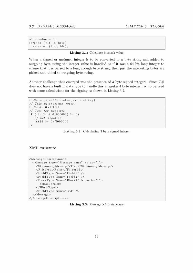
The message data is started with the message type id and after that all fields are enteredin order. Block type id and fields are added if existing. When doing this, all integersand strings are converted to byte strings with the help of the class BitConverter. Sinceall data in the outgoing byte string should be in network byte order, the integer bytestrings has to be reversed before added to outgoing byte string. If the value being addedto the outgoing byte string is a bit mask it has to be converted from the XML bit maskrepresentation to an unsigned integer. This is done by iterating all selected bits andadding them as shown in Listing 3.1.
13
3.3. DYNAMIC MESSAGES CHAPTER 3. TCCSIM
uint value = 0 ;f o r each ( b i t in b i t s )
va lue += (1 << b i t ) ;
Listing 3.1: Calculate bitmask value
When a signed or unsigned integer is to be converted to a byte string and added tooutgoing byte string the integer value is handled as if it was a 64 bit long integer toensure that it is parsed to a long enough byte string, then just the interesting bytes arepicked and added to outgoing byte string.
Another challenge that emerged was the presence of 3 byte signed integers. Since C#does not have a built in data type to handle this a regular 4 byte integer had to be usedwith some calculations for the signing as shown in Listing 3.2.
i n t24 = par s e32b i tva lue ( v a l u e s t r i n g )// Take i n t e r e s t i n g b y t e s .i n t24 &= 0 x f f f f f f// Test f o r nega t i v e .i f ( ( in t24 & 0x800000 ) != 0)
// Set nega t i v ei n t24 |= 0 xf f000000
f i
Listing 3.2: Calculating 3 byte signed integer
XML structure
<MessageDescr ipt ions><Message type=”Message name” value=”1 ”>
<StationaryMessage>True</StationaryMessage><Fi l t e r ed>False</F i l t e r ed><FieldType Name=”Fie ld1 ” /><FieldType Name=”Fie ld2 ” /><BlockType Name=”Block1 ” Numeric=”1 ”>
<Max>1</Max></BlockType><FieldType Name=”End” />
</Message></MessageDescr ipt ions>
Listing 3.3: Message XML structure
14

3.3. DYNAMIC MESSAGES CHAPTER 3. TCCSIM
<BlockDescr ipt ions><Block type=”Block1 ” value=”1 ”>
<FieldType Name=”Fie ld3 ”/><FieldType Name=”Fie ld4 ”/><FieldType Name=”Fie ld5 ” />
</Block></BlockDescr ipt ions>
Listing 3.4: Block XML structure
<Fie ldDes c r i p t i on s><F i e l dDe s c r i p t i on type=”Fie ld1 ”>
<Deta i l>Fie ld1 de s c r i p t i on </Deta i l><Length>2</Length><Min>1</Min><Max>65535</Max><Resolut ion></Resolut ion><Format>BITMASK</Format><Spec ia l>
<Bits><Bit value=”0 ”>Bit1 de s c r i p t i on </Bit><Bit value=”1 ”>Bit2 de s c r i p t i on </Bit>
</Bits></Spec ia l><Default></Default>
</F i e ldDesc r ip t i on></F i e l dDes c r i p t i on s>
Listing 3.5: Field XML structure
3.3.3 View Messages
TCCSim can translate a byte string of a message into a human readable format. Thisis done by fetching a message description from XML, either by knowing which messagetype or by reading the message type from the byte string. The message description isstored in an XElement. The case where the message type is know is when messages sentfrom TCCSim is parsed. This is used for faulty message definitions in the case of faultinjection in the message payload.
The fetched message description is used to know which field types that should be foundin the message byte string and which block types there is a possibility to find.
The parsing begins with reading all the message safety header fields. Each value is storedin a FieldType object. After all header values is fetched the message description is usedto fetch all field types in the message. Each field type is stored in a FieldType object.
15

3.4. COMMUNICATION MODULE CHAPTER 3. TCCSIM
If the message type can have any block types the payload is checked for this. Each blocktype with its fields are represented by a BlockType object. Each field type in the blockis stored as a FieldType object in the ArrayList of the BlockType. Which field typesthat a block type consist of is looked up by reading the block id from the message bytestring. That value is then used to look up the block name in the message descriptionwhich in turn is used to fetch the block description from the XML file describing allblock types. The message is searched for block types until an end of message marker isfound.
3.4 Communication Module
The communication module is responsible for all communication with the vehicle. Themodule is fed, by the main part of the application, with messages to send and it replieswith messages that is receives from the vehicle. The outgoing messages also passesthrough a safety layer which is included in the module. It also informs if any erroroccurs.
Since TCCSim is not dependant on what type of communication is being used thecommunication module should be a stand-alone part of the application. It is thereforcompiled as an application extension and included from a DLL file for the rest of theapplication to use.
This project uses TCP/IP as mean for external communication and this section of thereport describes how the module was designed. This includes choices made regarding theapplication protocol, ways of making the module stand-alone and how the safety layeris used.
3.4.1 Regarding the protocol
The application protocol that is specified for this system is a polling protocol meaningthat TCCSim will poll the vehicle with a fixed interval and wait for a response in betweenthese polls. The module therefor has to execute for as long as it is active. Knowing thatthis is a user interactive application, having the process executing indefinitely will makethe GUI totally unresponsive. Instead the communication will be executed in a differentthread and report progress to the main thread.
Since the other modules of the application is passing around information using C#’sevents, it would be a good thing if the communication thread and the main thread werejoint in the same manner. This would allow the communication between the threads
16

3.4. COMMUNICATION MODULE CHAPTER 3. TCCSIM
to be completely asynchronous. Events themselves have however no recollection of inwhat thread an event should or should not be executed. Firing an event from one threadmeans that the same thread will execute the event handler registered to that event. C#,though, have the ability to marshal events between threads and this becomes very easywith the existing class BackgroundWorker. It is built to pass information between a userinterface thread and a thread doing lengthy executions in the background. Informationpassed from the communication thread includes the actual messages being delivered,errors regarding faulty connection data, errors regarding the connection or the lack ofbeing able to establish a connection.
The old system, which is being replaced, is using an application protocol developedfor serial communication. The new system’s protocol will be very similar to the oldprotocol since serial communication might be used again in the future. This means thatthis module will have to handle the incoming data as if it was transfered using serialcommunication. This includes searching through the incoming stream of bytes for themessage start value “<STX>” and reckon with receiving fragmented messages. Thisapproach also eases testing since old testing equipment can be used to test TCCSimwhen new hardware is not available.
3.4.2 Stand-alone Module
Since the system simulated by TCCSim might change in the future this communicationmodule has to be as little attached to the rest of the application as possible. Onlythe application protocol is certain to remain while all lower level protocols might beexchanged. Therefor the module is built as a separate DLL file, which means that it islike any other external program, unable to depend on functions in the application. Themodule contains three main classes. The communication class, an abstract class whichthe communication class inherits and the safety layer class. The abstract and safety classshould not need to be changed when changing the communication architecture unless,of course, there are changes regarding the safety layer. The abstract class is createdto make the structure and the development of a new communication class easier anddoes not have anything to do with the actual communication architecture. Alongsidethese main classes there are five classes used to pass information when events are fired.It is hard to know in advance, but these five classes inheriting C#’s EventArgs classshould be enough even in future development. They are used to deliver messages, passinformation on the connection status and to report unknown errors.
Making the module stand-alone means also making the user interface independent ofwhat type of communication architecture being used. This includes input of connec-tion data. In this project that means to input a destination IP address and TCP port.Two fields to input this data might be enough and it might not when TCP/IP is being
17

3.4. COMMUNICATION MODULE CHAPTER 3. TCCSIM
exchanged for something else. This is why the two field was merged to a single field.In this case it means giving the data in the form “<IP address>:<TCP port>”. Thecommunication class will have to parse the data in the appropriate way for the commu-nication architecture it is developed for. When delivered messages are being displayedby the main view the connection data is unessential. Only which train, given by an IDfrom the safety header, is necessary to show. The safety header, as described in Section2.7, is completely separated from the underlying communication architecture.
3.4.3 Safety Layer
Every message, inbound or outbound, starts with a safety header. It starts with a valuecalled <STX> which is a first check that the message is usable after receipt. Any errorsencountered are noted but the message is still delivered since it is valuable informationto the user.
The time stamp containing the time of the send out should have an increased value foreach sent message but it should, however, also support roll-over. TCCSim checks thisby calculating the difference between the previous value received and the current value,with roll-over awareness. If the difference exceeds the maximum value of the polling in-terval and the timeout value times two, it is not seen as a roll-over but an error. Shownin Listing 3.6.
i f ( Current Timestamp < Prev Timestamp && (Current Timestamp −Prev Timestamp + 65535) > (Max( Po l l i n g I n t e r v a l , Timeout Value ) ∗ 2) )
Timestamp Error = true ;f i
Listing 3.6: Check if a time stamp error has occurred
The CRC calculations specified for this system appears not to be standard calculations.Therefor existing C code from the live system was brought into TCCSim and calledfrom C# code with Platform Invocation Services[8] (PInvoke). PInvoke allows managedcode to call unmanaged code in the .NET platform. The C code uses a table lookupalgorithm[9] to increase speed when calculating the CRC. The same technique is usedwhen calculating the BCC but this algorithm is translated from the provided C code toC# code.
18

3.4. COMMUNICATION MODULE CHAPTER 3. TCCSIM
3.4.4 Work Flow
When the thread executing in the communication module is started, it first verifies thatconnection data and timer values are in order. If there is anything wrong, the user isinformed and the thread is self aborted.
If everything is in order the execution enters the main loop and stays until told to abort.The loop contains all necessary parts for the communication to never cease. At the startof every round the status of the TCP connection is checked to be connected. If thereis no connection, establishing one is priority one and it will be priority one until theconnection is established or the thread is aborted. Either way, the user is informed viaevents on what the status is.
Next step is to send a message to the vehicle. Since there always has to be a messagesent with a fixed interval a default message is given the module at initialization. Thisdefault message is imported from an XML file and can therefor be changed after compiletime. If the user has not provided a different message to send the default message willalways be sent. The safety header is then calculated and added to the chosen messageas described in Section 2.7. Since the protocol is developed with serial communicationin mind, five bytes are appended to the front of the message and one to the back withvalue E716.
A response from the vehicle is then to be expected. When the communication socket isinitialized a timeout value is set. If no response is received within this time somethinghas gone wrong, the socket is closed and the main loop is started from the beginning.When a response is received, first the value <STX> is sought. When what seems to be<STX> is found, the safety header i.e. the next seven bytes is brought into memory.The total length of the message is checked and also brought into memory. If the lengthexceeds the maximum value of how long a message is allowed to be it was not thecorrect <STX> that was found. The same conclusion is taken if not enough bytes fromthe socket was available before timeout was experienced or if the BCC calculation of thereceived message fails. In this case, <STX> is sought once again. This time from theposition after the previous <STX> was found. This continues until the correct <STX>is found or until no more data from the socket is available. If <STX> is never foundthe connection times out and a new connection has to be established.
The communication module should have as little as possible to do with the contentsof the received messages. But the time stamp fields has to be checked by the modulesince time stamp error has to be looked for. The results of this and the message is thendelivered to the main thread.
In addition to this there are also thread safe flags which are controlled by the main
19

3.5. FAULT INJECTION CHAPTER 3. TCCSIM
thread. One flag that enables pause. When it is set there is no messages sent or receivedand the current state of the connection is unchanged as far as the module knows. Otherflags are used to inject errors in the safety header. More about this in Section 3.5.
3.5 Fault Injection
By enabling the ability to inject faults into outbound messages more thorough tests canbe performed. It allows for the system undergoing the tests to be presented with datawhich are not according to specifications. This section handles the different methods ofinjecting these faults.
3.5.1 Safety Header
A number of different scenarios are possible when injecting errors into the safety header.The number is although limited to the degree that it will be enough to declare a flag foreach type of error injected. The value of the flags is given to the safety layer class eachtime the safety header for an outbound message is calculated. When a flag is set it willonly affect the next outbound message and then it will be reset.
The interesting fields for injecting errors in the safety header is ID, T SENDER, T REF,CRC and BCC(see Figure 2.1). The ID field is used to double check what recipient themessage was intended to (apart from the communication endpoint). When giving a faultyID, the new value is picked at random but still parted from the correct value.
For each sent message the time stamp value of T SENDER should be increasing (withthe exception of roll-over). Two options for injecting fault to this fields is consequentlypossible. If message M is sent with time stamp T0 the subsequent sent message M ′
should have a time stamp T1 > T0. The first possibility for injecting a fault is to letT1 = T0. It would mean the previous message M is being resent. The other possibilityis T1 < T0 which means that the receiver of M ′ has received an old message. Both ofthese injections are controlled with one flag each. Of course only one of the faults canbe staged on each message.
The time stamp reference field T REF should contain the last time stamp value thatwas received. When receiving message M with time stamp T , the response M ′ shouldtherefor contain the time stamp reference value R = T . The two different possibilitiesfor injecting faults to this field is consequently R < T and R > T . Each of the cases iscontrolled by a flag.
20

3.6. SCRIPT CHAPTER 3. TCCSIM
The transmission error detection fields CRC and BCC can be changed to not correspondwith the actual calculated values. Each of the fields are controlled with a flag. When aflag is set a random number is added to the calculated value to simulate a transmissionerror. The added value is chosen to not make the calculated value to be chosen again inthe event of roll-over.
3.5.2 Erroneous messages
By the design choice to put all the message descriptive data in external configurationfiles, there is an opportunity to easily create messages that behave outside of the protocol.Errors that can be induced are field data out of bounds, block types that should notexist in a given message type. Block types can be set up to exists too many times in amessage. Extra fields can be added to a message or block, this will disrupt the parsingof the message from that point on.
To create a faulty block, field, or message type a new type has to be added to thecorresponding XML-file with the same id as the correct type that is desired to spoof. Itcannot have the same name as the correct type since block, field and message types areidentified by their names by TCCSim.
3.6 Script
With the ability for a user of TCCSim to write scripts and execute them opens thepossibilities to optimize the usage of the application. It would be more efficient andmore exact to let a script handle all events when communicating with a vehicle. Thissection describes how this was solved while Section 4.5 describes why this path wastaken.
3.6.1 Overall Structure
A Python script has to be written in a third party text editor. The complete scriptis then loaded into TCCSim via the application’s main view where it is interpreted byIronPython (described in Section 2.4). The script can be loaded in which ever stateTCCSim happens to be (connected/disconnected). Preferably the script is suited tostart in that state, which is up to the user to ensure. All state changes the scriptperforms is recorded and will be adopted by the GUI when the script returns. All of
21
3.6. SCRIPT CHAPTER 3. TCCSIM
the GUI’s functionality to interact with the ongoing conversation is disabled while thescript executes.
The GUI cannot be completely disabled or frozen if the script should be of any use tothe user. For this to be at all possible the script has to execute in its own thread. Onceagain, as with the communication module, the BackgroundWorker from C#’s librarieswas used. When a script is loaded, the BackgroundWorker will start to run the script inthe background. It will use the report progress feature to interact with the main thread.This way, inbound and outbound messages will be displayed in the main view as usualand the user will be able to analyse the content of the messages by clicking them. Thescript returns when it is finished or the user can cancel the script at any time.
3.6.2 Script Functionality
If a written script should be of any use it has to reach key functions in TCCSim’s arsenal.These functions are gathered in a class called Script, which is also the class that calls thescript. When an instance of Script calls a given script it attaches itself to the call. Whenthe script runs it will be able to call public functions of that instance. It is importantto limit what a script should and should not be able to reach inside TCCSim since thescript runs in a separate thread. A writer of a script cannot determine what functionscan be called in a thread safe manner which means these public functions will have tobe thread safe by nature. As mentioned in the previous section the script thread usesBackgroudWorker’s progress reports to interact with the main thread.
The functions that a script has at its disposal includes connect, disconnect, pause/un-pause, send messages, read messages, injecting faults into outbound messages, and theability to load messages and manipulate them. Apart from these TCCSim bound func-tionalities, the implemented functionality of IronPython is also available. This does notinclude all Python features since IronPython at the time of writing is a work in progress.It does, however, mean any available C# library can be imported and used. This addsup to a very powerful scripting implementation.
3.6.3 Print
It is convenient to output text when running a script. Since TCCSim is not a consoleapplication another method than STDOUT would have to be used for printing. A newtab to the main view’s lower part was added. The tab contains a TextBox with the looksand functionality of a output window. When printing from a script the output will beadded to this TextBox.
22

3.6. SCRIPT CHAPTER 3. TCCSIM
IronPython provides the opportunity to redirect STDOUT of a running script to aStreamWriter. A new class called ScriptStream, which inherits StreamWriter, was cre-ated and given as output stream. A ScriptStream is given a BackgroundWorker, whichis used by the script to communicate between threads. When writing to an instance ofScriptStream it will use the provided BackgroudWorker to send an event to the mainthread and by that output text to the output TextBox. This technique makes it possibleto use IronPython’s default printing function to output text which appears in TCCSim’smain view.
23

4
Design Choices
This chapters motivates the choice of method.
4.1 User Interface
The new user interface have been designed with the idea of make it more intuitive,reviewable, and fitting for the task. This have been achieved by looking at the oldsimulator’s interface and learning what was good and not good. An open dialogue withthe employer were held throughout the project to further make the interface fit theirneeds.
4.1.1 Message creation
The interface for creating messages was iteratively developed by a dialogue with theemployer. Demands were that a more reviewable interface than the previous one (seenin Figure 4.1) should be created.
Another desire was that the interface should be browsable by just keyboard input. Con-sidering this, and that the content of each message type is unknown, an interface whereeach value is entered in a top down approach were presented. The idea was liked by theemployer and inferred in TCCSim and can be seen in Figure 3.4.
24

4.2. DYNAMIC MESSAGES CHAPTER 4. DESIGN CHOICES
Figure 4.1: Old message editor
4.2 Dynamic Messages
4.2.1 Identification by name
The protocol identifies different message and block types by their numeric ids. In TCC-Sim they are instead identified by their names when possible, which is the case for alloutgoing messages. For incoming messages only the numeric id is known. The reasonfor using names is to allow multiple message and block types with the same id in theprotocol definition. This is used to be able to create faulty messages to be used whentesting. For example, to test what happens when a message is longer than expected or
25

4.3. COMMUNICATION MODULE CHAPTER 4. DESIGN CHOICES
contains values out of bounds for what is expected.
4.2.2 Data types
FieldType
A FieldType is a data type for storing information about field types when they are parsedfrom a byte string of a message. In a FieldType there is a string for storing the nameof the field stored in the FieldType and an ArrayList for the field data. The reason forhaving an ArrayList here is that the data in a field can vary between an integer, a stringor a bitmask. Where integers and strings only need one object to represent its data inhuman readable form, bitmasks needs one object for each set bit.
BlockType
The BlockType data type consist of the same data objects as the FieldType. A string forthe block name and an ArrayList for storing data. In the ArrayList objects of FieldTypeis stored for the field types that the block is built from. The reason for an additionaldata type where only the name differs from FieldType is to make it much easier for theprogrammer to differ a block from a field.
4.3 Communication Module
The main part of TCCSim and the communication module is executed in separatethreads which means the threads have to communicate with each other in some way.The main part of the application uses events to pass information around. Since eventsdo not have any awareness regarding threads, that approach could not be used withoutmodification.
Since the communication thread is being fed, with messages to send, by the main thread,one option could be to use the same technique in reverse. The communication threadwould, in this case, insert status updates and deliver messages by inserting the theminto a list. The problem is that the main thread would have to take part of the insertedinformation in some way. It would be very inefficient and would make the user interfacesomewhat unresponsive to make the main thread poll the list at a given rate and thereforthis idea was abandoned.
26
4.4. FAULT INJECTION CHAPTER 4. DESIGN CHOICES
C# has the ability to marshal event between threads. For example, control objects thatare used in Windows Forms remembers what thread they were created in. When tryingto make changes to the object a check can be made to see if the thread trying to make thechange is the same thread that created to object. If not, the execution can be marshalledto the correct thread and the change can be made. This method would, however, be veryprone to errors since all changes to objects in the form would have to be preceded withthis check. Also, all object which do not possess this thread checking ability could bealtered by more than one thread at once, assuming no semaphores would be used.
Instead the existing C# class BackgroundWorker was used. It was created to run lengthyexecutions in the background with the ability to send status updates to a user interface.When sending a status update from the background thread it automatically marshalsthe event to the thread which created the BackgroundWorker object. This was the mostconvenient solution since no consideration to thread safety had to be taken when updateswere sent. The main thread would also handle these events asynchronous which makesthe solution efficient.
4.4 Fault Injection
Since the vehicle essentially is a finite state machine, testing methods aimed at thesetypes of systems is applicable. Sidhu et al. [10] describes four types of methods fortesting protocols defined using Mealy state machines. These methods are all possible touse for testing with TCCSim since any type of message can be sent at any given time.Because of this property, also incorrect sequences of messages can be staged, thus testingthe stability of the protocol.
4.4.1 Erroneous messages
By the design choice to put all the message descriptive data in external configuration filesthere is easy to create messages that behave outside of the protocol. To create a messagethat have some data out of order, data that should not exist in given message type orsimilar, a message type with desired message id is added to the message descriptions.Since the faulty message type have the same id as the correct one, the program have toknow the name of the new message type associated to such a byte string to be able toparse it.
Many of the vulnerabilities with software is robustness problems[11]. These types ofproblems most often comes to light when invalid input data is given the application. Mostoften robustness tests expects the application to crash or an exception being thrown.
27

4.5. SCRIPT CHAPTER 4. DESIGN CHOICES
With TCCSim’s ability to specify any kind of structure for a message the robustness ofthe protocol and the vehicle software can be tested.
Other options that were evaluated were the possibility to randomly alter some datain the payload. This was discarded due to that it would render uncontrollable errors.Errors of this kind would have no value in the application of TCCSim. This since whenTCCSim is used in test cases it is desirable to know what caused an error, not just thatan error occurred. Otherwise random errors is an effective tool for testing robustness ofapplications according to Duran et al. [12]
4.5 Script
In the evaluation process of the possibility to introduce scripting ability in TCCSimone option evaluated was to implement a scripting language just for TCCSim. Thiswas rather quickly abandoned since even a very simple language would have been tooextensive for this project. It was not justifiable go through the process with inventinga syntax and for that implement lexing, parsing, type checking and code generation forsuch a small part of the project. [13]
The other option evaluated was to utilise an already implemented language with TCC-Sim. When looking for alternatives Python, via IronPython, and Lua, via LuaInterface,was found to be the alternatives that were the most developed and straight forwardoptions. Both alternatives were easy to integrate in our tests. The reason for the choiceof IronPython was that the personal at Bombardier favoured Python over Lua.
There is many other options for integration of interpreters exists, but none as wellsupported and documented than the evaluated alternatives. The option of dynamicallyexecute C# code from TCCSim was not evaluated more than it was rejected directlysince a simpler syntax were sought.
28

5
Testing
TCCSim has no specified behaviour and testing the application is therefor not straightforward. Most of the testing will be concerning the functionality of the application andthus making sure it will not crash. First a more in depth white box testing will beperformed, followed by a more black box oriented approach.
5.1 White Box Testing
With this testing method the internal structures of the program is considered. Henchthe name white box, thus the tester have full disclosure of the internal structures of theprogram. Sometimes also known as clear box or glass box testing. Units or modules ofthe code are tested with white box testing.
5.1.1 Parameterized Unit Tests
By using Pex[14], a specific kind of white box testing called Parameterized Unit Test(PUT)can be performed. PUTs are axiomatic specifications and aims at full coverage whendoing test runs[15]. Pex analysis the code of the application and generates test cases rel-evant to what has been observed. Many of TCCSim’s classes and functions do howeverhave rather complex input data such as XML structures and data sockets. Pex does nothandle this well and will therefor only be available to use at some degree.
29

5.2. BLACK BOX TESTING CHAPTER 5. TESTING
5.2 Black Box Testing
No true black box testing can be performed at this stage since the developers of TCCSimis also the testers. The underlying structure of the code is known when testing. Theapplication will, however, be tested by simply using it in possible scenarios that a userwill and might encounter. At the time of testing no live hardware was available norwas the protocol specification definitive. Instead an old test system was used as vehiclefor TCCSim to communicate with. This was possible since TCCSim is able to easilyswitch between different protocol specifications as described in Section 3.3. Since theold system communicates via serial port an IP-to-serial-port translator was also used inbetween.
5.3 Test Results
5.3.1 White Box
Most of the white box test cases that were carried out showed that input variables andreturn values has to be checked for null value and that array lengths are sufficient. Amore unexpected problem was discovered in the communication module. If a vehiclesends trash data, which looks like a message, in front of the actual message, the TCPconnection might timeout waiting for more data on the socket. This was fixed withselect() which do not timeout the TCP connection even if no data was recorded. Insteadthe actual message is found and delivered.
5.3.2 Pex
The test cases that were generated by Pex revealed that either the input parameters mustbe checked for null value or that arrays must be checked to be of sufficient length.
5.3.3 Black Box
The black box tests shows that TCCSim has no problem communicating with the oldtest system. The test that was mainly performed is a startup sequence which requires anumber of messages to be exchanged in a correct order. The messages were created andsaved to file using the message creation interface. The sequence of messages were sent
30

5.3. TEST RESULTS CHAPTER 5. TESTING
both manually and by script. During the tests other TCCSim features such as injectingfaults into the safety header and filtering the transfer log were used.
31

6
Results
Evaluating the results of this project will not be totally objective. This may not beneeded since the scope of this project is not about comparing different testing environ-ments rather develop an environment that fulfill the needs of the employer.
The main interface of TCCSim provides the basic functionality such as sending messagesand analyse transfered messages. The outline of a conversation with a vehicle is easyto apprehend because of the message filtering feature. The content of the messages isclearly presented in both readable and raw data output. Full transfer logs can be savedfor later viewing.
Creating messages to be sent is performed with the message creation interface. It allowsfast input of data with the ability to tab through the input fields. Only the necessaryfields are displayed to not clutter the interface. After creating a message it can either besent or saved to file. The XML format which the files are stored in makes it easy changethe content by hand or transfer the files between computers.
Since the TCP/IP communication should be easily exchangeable it was built as a separatemodule and included as a DLL. The GUI was also adapted to this with a single textfield to input connection data. During the project a second version of TCCSim wasdeveloped called TCCsimRS232. External serial port communication code, from theprevious simulator(mentioned in Section 2.6), was brought into TCCSim and replacedthe TCP/IP code. Only the communication module DLL had to be rebuilt for this towork which proves the point that the means of communication is easily exchangeable inTCCSim.
32

CHAPTER 6. RESULTS
Since the protocol definition of TCCSim is stored externally in XML files, injectingfaults is very easy. Any kind of message may be defined which means the possibilities ofcreating erroneous messages are endless. This in combination with injecting faults intothe safety header adds up to a powerful solution.
The ability to script the behaviour of TCCSim was implemented using IronPython. Thefunctionality of the scripts are more or less the same as the application in general. Theonly drawback is the inability to create a new message from scratch in a simple way.This is still a powerful tool when doing extensible test cases.
Since TCCSim has the ability to define the protocol externally and the fact that a serialport communication module was developed in parallel, the application is completelyusable with the old system. Due to this and the fact that TCCSim is more comprehensiveand easier to work with it was inferred as a replacement of the old simulator, which gavesome real world testing.
33
7
Future Development
7.1 Remote
The possibility to alter TCCSim for remote management have been researched. Thetest showed that it would be easy to replace the graphical user interfaces with a consoleapplication listening for connections and handling requests. Only modifications neededfor this is to make a few changes in the controller to use the server view instead of thegraphical view. The server is just registered to the eventhandlers and can choose tohandle which events that is necessary.
The reason to not further develop a remote version of TCCSim is that there is noapplication for this in the current test environment.
7.2 More Than One Vehicle
To add support for handling more than one vehicle in TCCSim have not been evaluated.But one idea to implement a solution for that would be to develop the remote manage-ability of TCCSim and then use some program to handle several remotes at the sametime.
34

8
Conclusion
Having a good and modular design pattern renders the application to be easy to extendwith new functionality, and also reuse functionality. In TCCSim, an application were theprogram performs both data and user interaction, the powers of MVC appears clearly.The MVC design pattern made it easy to extend the program with scripting ability bysimply attaching a scripting language to the application. The strength of MVC were alsoseen when remote management was evaluated. By removing the graphical user interfaceand hooking up a server object to the events for user interaction a whole new applicationwas created.
Having continuously input from the employer is helpful to ensure that the final productperforms and behaves like expected. This also ensures that unnecessary features of theproduct is not implemented.
By making the protocol dynamically reconfigurable the scope of use for the applicationis much larger by being able to alter it for different projects and environments. This wasexemplified in this case by the fact that TCCSim were adapted to the old environmentand replacing the simulation software previously used. Having the protocol easily recon-figurable also increases the number of possible test cases with the possibility to easilyinfer controlled errors in the testing.
35

9
Discussion
During the development there was never any possibility to test towards the system thesimulator was meant to be used with. Fortunately by inferring the old protocol specifica-tion in TCCSim and some means to redirect IP communication to RS232 communication,testing could be performed towards the old system. This was very useful in the develop-ment process since it revealed problems not thought of and that would not have emergedduring the tests towards a simple replication service. Due to the adaptability of the pro-tocol specification handled by TCCSim this testing should be sufficient for when the newsystem is specified. Event though it would have been nice to been able to test it towardsthe intended system and by that confirm this since some modifications might have to bedone to adjust the differences between TCP/IP and RS232 communication.
If TCCSim should be able to handle more than one vehicle at the time it would havebeen easier to implement this if that feature were considered more during the initialdevelopment phase. But considering how different communication methods uses differentconnection methods, this would have rendered the communication module to be muchmore extensive and complicated. For example with a radio protocol all communication isbroadcasted to all vehicles at the same time, but with TCP a connection to each vehicleis established were just messages interesting for that vehicle is delivered.
36

References
[1] Bombardier awards (2011).URL http://www.bombardier.com/en/transportation/about-
transportation/awards?docID=0901260d800d8189
[2] Extensible markup language (xml) (2011-07-08).URL http://www.w3.org/XML/
[3] C. Nagel, B. Evjen, J. Glynn, K. Watson, M. Skinner, Professional C# 2008, WileyPublishing, Inc., Indianapolis, 2008.
[4] Garbage collection ((2011-03-29)).URL http://msdn.microsoft.com/en-us/library/ms228629(VS.80).aspx
[5] Type safe (2011-03-29).URL http://msdn.microsoft.com/en-us/library/ms173104.aspx#Y100
[6] Ironpython (2011-03-29).URL http://ironpython.net/
[7] E. Meijer, B. Beckman, G. Bierman, Linq: reconciling object, relations and xmlin the .net framework, in: Proceedings of the 2006 ACM SIGMOD internationalconference on Management of data, SIGMOD ’06, ACM, New York, NY, USA,2006, pp. 706–706.URL http://doi.acm.org/10.1145/1142473.1142552
[8] Platform invoke tutorial (2011-05-18).URL http://msdn.microsoft.com/en-us/library/aa288468(v=VS.71).aspx
[9] T. Ramabadran, S. Gaitonde, A tutorial on crc computations, Micro, IEEE vol.8 (nr. 4) (1988) p. 62.
[10] D. Sidhu, T.-K. Leung, Formal methods for protocol testing: A detailed study,Software Engineering, IEEE Transactions on 15 (Issue:4) (1989) p. 413.
37

REFERENCES
[11] R. Kaksonen, A functional method for assessing protocol implementation security(2001).
[12] J. W. Duran, S. C. Ntafos, An Evaluation of Random Testing, Software Engineering,IEEE Transactions on SE-10 (Issue:4) (1984) p. 438–444.URL http://ieeexplore.ieee.org/xpl/freeabs_all.jsp?arnumber=5010257
[13] A. V. Aho, M. S. Lam, R. Sethi, J. D. Ullman, Compilers: Principles, Techniques,& Tools with Gradiance (pkg), 2/E, Prentice Hall, 2007.
[14] Pex (2011-07-05).URL http://research.microsoft.com/en-us/projects/pex/
[15] N. Tillmann, W. Schulte, Parameterized unit tests, One Microsoft Way.
38

A
UML
Figure A.1: TCCSim UML
39
![[MS-DHCPE]: Dynamic Host Configuration Protocol …...Dynamic Host Configuration Protocol (DHCP) Extensions Intellectual Property Rights Notice for Open Specifications Documentation](https://static.fdocuments.in/doc/165x107/5f4bcaf6c73ffb6385247ba1/ms-dhcpe-dynamic-host-configuration-protocol-dynamic-host-configuration-protocol.jpg)


![[MS-DHCPM-Diff]: Microsoft Dynamic Host Configuration Protocol (DHCP) Server …... · 2017. 5. 25. · Microsoft Dynamic Host Configuration Protocol (DHCP) Server Management Protocol](https://static.fdocuments.in/doc/165x107/614788e9afbe1968d37a1cf4/ms-dhcpm-diff-microsoft-dynamic-host-configuration-protocol-dhcp-server-.jpg)