Dynamic Multipoint VPN (DMVPN) Deployment...
102
Transcript of Dynamic Multipoint VPN (DMVPN) Deployment...


© 2012 Cisco and/or its affiliates. All rights reserved.BRKSEC-4054 Cisco Public 2
Dynamic Multipoint VPN (DMVPN)Deployment ModelsBRKSEC-4054

© 2012 Cisco and/or its affiliates. All rights reserved.BRKSEC-4054 Cisco Public 3
DMVPN Overview
NHRP Details
Deployment Models
Recent and New Features
Agenda

DMVPN Overview

© 2012 Cisco and/or its affiliates. All rights reserved.BRKSEC-4054 Cisco Public 5
What is Dynamic Multipoint VPN?
DMVPN is a Cisco IOS software solution for building IPsec+GRE VPNsin an easy, dynamic and scalable manner
Relies on two proven technologies
‒ Next Hop Resolution Protocol (NHRP)
Creates a distributed mapping database ofVPN (tunnel interface) to real (public interface) addresses
‒ Multipoint GRE Tunnel Interface
Single GRE interface to support multiple GRE/IPsec tunnels and endpoints
Simplifies size and complexity of configuration
Supports dynamic tunnel creation

© 2012 Cisco and/or its affiliates. All rights reserved.BRKSEC-4054 Cisco Public 6
DMVPN: Major Features
Configuration reduction and no-touch deployment
Supports:
‒ Passenger protocols (IP(v4/v6) unicast, multicast and dynamic Routing Protocols)
‒ Transport protocols (NBMA) (IPv4 and IPv6)
‒ Remote peers with dynamically assigned transport addresses.
‒ Spoke routers behind dynamic NAT; Hub routers behind static NAT.
Dynamic spoke-spoke tunnels for partial/full mesh scaling.
Can be used without IPsec Encryption
Works with MPLS; GRE tunnels and/or data packets in VRFs and MPLS switching over the tunnels
Wide variety of network designs and options.

© 2012 Cisco and/or its affiliates. All rights reserved.BRKSEC-4054 Cisco Public 7
DMVPN: How it works
Spokes build a dynamic permanent GRE/IPsec tunnel to the hub, but not to other spokes. They register as clients of the NHRP server (hub).
When a spoke needs to send a packet to a destination (private) subnet behind another spoke, it queries via NHRP for the real (outside) address of the destination spoke.
Now the originating spoke can initiate a dynamic GRE/IPsec tunnel to the target spoke (because it knows the peer address).
The dynamic spoke-to-spoke tunnel is built over the mGRE interface.
When traffic ceases then the spoke-to-spoke tunnel is removed.

© 2012 Cisco and/or its affiliates. All rights reserved.BRKSEC-4054 Cisco Public 8
DMVPN: Example
Dynamic Spoke-to-spoke tunnels
Spoke A
Spoke B
192.168.2.0/24
.1
192.168.1.0/24
.1
192.168.0.0/24
.1
. . .
Physical: 172.17.0.1
Tunnel0: 10.0.0.1
Physical: dynamic
Tunnel0: 10.0.0.11
Physical: dynamic
Tunnel0: 10.0.0.12
Static Spoke-to-hub tunnels
Static known
IP address
Dynamicunknown
IP addresses
LANs can have
private addressing

© 2012 Cisco and/or its affiliates. All rights reserved.BRKSEC-4054 Cisco Public 9
NHRP Registrations
‒ Spoke (NHC) dynamically register its VPN to NBMA address mappingwith hub (NHS).
Static NHRP mappings on spokes for Hub (NHS)
Needed to “start the game”
Builds hub-and-spoke control plane network
NHRP Resolutions
‒ Dynamically resolve spoke to spoke VPN to NBMA mapping to buildspoke-spoke tunnels.
‒ Single instead of multiple tunnel hops across NBMA network
‒ NHRP Resolution requests sent via hub-and-spoke path
‒ NHRP Resolution replies sent via direct spoke-spoke path
NHRP Main Functionality

© 2012 Cisco and/or its affiliates. All rights reserved.BRKSEC-4054 Cisco Public 10
IPsec integrated with DMVPN, but not required
Packets Encapsulated in GRE, then Encrypted with IPsec
NHRP controls the tunnels, IPsec does encryption
Bringing up a tunnel
‒ NHRP signals IPsec to setup encryption
‒ ISAKMP authenticates peer, generates SAs
‒ IPsec responds to NHRP and the tunnel is activated
‒ All NHRP and data traffic is Encrypted
Bringing down a tunnel
‒ NHRP signals IPsec to tear down tunnel
‒ IPsec can signal NHRP if encryption is cleared or lost
ISAKMP Keepalives monitor state of spoke-spoke tunnels
DMVPN and IPsec

© 2012 Cisco and/or its affiliates. All rights reserved.BRKSEC-4054 Cisco Public 11
Hubs are routing neighbors with spokes
‒ Receive spoke network routes from spokes
‒ Advertise spoke and local networks to all spokes
‒ All Phases:
Turn off split-horizon (EIGRP, RIP); Single area and no summarization (OSPF)
‒ Phase 1 & 3:
Hubs must not preserve original IP next-hop; Can Summarize
iBGP (next-hop-self);
EIGRP, eBGP (default);
OSPF (network point-multipoint, # hubs not limited)
‒ Phase 2:
Hubs must preserve original IP next-hop; Cannot summarize
EIGRP, eBGP (no ip next-hop-self);
iBGP (default);
OSPF (network broadcast, Only 2 hubs)
Routing

© 2012 Cisco and/or its affiliates. All rights reserved.BRKSEC-4054 Cisco Public 12
Hubs are routing neighbors with other hubs
‒ Phase 1 & 3:
Can use different routing protocol than on hub-spoke tunnels
‒ Phase 2:
Must use same routing protocol as on hub-spoke tunnels
Spokes are only routing neighbors with hubs, not with other spokes
‒ Spokes advertise local networks to hubs
Routing (cont)

© 2012 Cisco and/or its affiliates. All rights reserved.BRKSEC-4054 Cisco Public 13
Routing Table Example (Spoke)
C 172.16.1.0/30 is directly connected, Serial1/0C 10.0.0.0/24 is directly connected, Tunnel0C 192.168.1.0/24 is directly connected, Ethernet0/0S* 0.0.0.0/0 is directly connected, Serial1/0D 192.168.0.0/16 [90/2841600] via 10.0.0.1, 00:00:08, Tunnel0
C 172.16.1.0/30 is directly connected, Serial1/0C 10.0.0.0/24 is directly connected, Tunnel0D 192.168.0.0/24 [90/297372416] via 10.0.0.1, 00:42:34, Tunnel0C 192.168.1.0/24 is directly connected, Ethernet0/0D 192.168.2.0/24 [90/297321216] via 10.0.0.12, 00:42:34, Tunnel0D 192.168.3.0/24 [90/297321216] via 10.0.0.13, 00:42:34. Tunnel0. . .S* 0.0.0.0/0 [1/0] via 172.16.1.1
Phase 1 & 3(with summarization)
Phase 2(no summarization,
next-hop preserved )
C 172.16.1.0/30 is directly connected, Serial1/0C 10.0.0.0/24 is directly connected, Tunnel0D 192.168.0.0/24 [90/297372416] via 10.0.0.1, 00:02:36, Tunnel0C 192.168.1.0/24 is directly connected, Ethernet0/0D 192.168.2.0/24 [90/297321216] via 10.0.0.1, 00:02:36, Tunnel0D 192.168.3.0/24 [90/297321216] via 10.0.0.1, 00:02:36, Tunnel0. . .S* 0.0.0.0/0 [1/0] via 172.16.1.1
Phase 1 & 3(without summarization,next-hop not preserved)

© 2012 Cisco and/or its affiliates. All rights reserved.BRKSEC-4054 Cisco Public 14
Active-active redundancy model – two or more hubs per spoke
‒ All configured hubs are active and are routing neighbors with spokes
‒ Routing protocol routes are used to determine traffic forwarding
Single route: one tunnel (hub) at a time – primary/backup mode
Multiple routes: both tunnels (hubs) – load-balancing mode
ISAKMP/IPsec
‒ Cannot use IPsec Stateful failover (NHRP isn‟t supported)
‒ ISAKMP invalid SPI recovery is not useful with DMVPN
‒ ISAKMP keepalives on spokes for timely hub recovery
crypto isakmp keepalives initial retry
Redundancy

© 2012 Cisco and/or its affiliates. All rights reserved.BRKSEC-4054 Cisco Public 15
Can use single or multiple DMVPNs for redundancy
‒ Each mGRE interface is a separate DMVPN network usingdifferent tunnel key, NHRP network-id and IP subnet
‒ Can “glue” mGRE interfaces into same DMVPN network(*)
same tunnel source, NHRP network-id and authentication,no tunnel key and different IP subnet (Phase 3 only)
‒ If using same tunnel source (must use tunnel key)
tunnel protection ipsec profile name shared
Spokes – at least two hubs (NHSs)
‒ Phase 1: (Hub-and-spoke)
p-pGRE interfaces two DMVPN networks, one hub on each
‒ Phase 1, 2 or 3: (Hub-and-spoke or Dynamic Mesh)
mGRE interface one DMVPN network, two or more hubs
Redundancy (cont)

© 2012 Cisco and/or its affiliates. All rights reserved.BRKSEC-4054 Cisco Public 16
Hubs – interconnect and routing
‒ Phase 1: (Hub and spoke only)
Interconnect hubs directly over physical link, p-pGRE or mGRE
Hubs can exchange routing through any of these paths
‒ Phase 2: (Dynamic Mesh)
Interconnect hubs over same mGRE, daisy-chain as NHSs
Hubs must exchange routing over DMVPN network
‒ Phase 3: (Dynamic Mesh)
Interconnect hubs over same or different mGRE (same DMVPN)
Hubs must exchange routing over DMVPN network
Redundancy (cont)

© 2012 Cisco and/or its affiliates. All rights reserved.BRKSEC-4054 Cisco Public 17
Resiliency
‒ No monitoring of spoke-spoke tunnel (use ISAKMP keepalives)
crypto isakmp keepalives initial retry
Path Selection
‒ NHRP will always build spoke-spoke tunnel
‒ No latency measurement of spoke-spoke vs spoke-hub-spoke paths
Overloading spoke routers
‒ CPU or memory IKE Call Admission Control (CAC)
crypto call admission limit ike {sa | in-negotiation } max-SAs
call admission limit percent
show crypto call admission statistics
‒ Bandwidth Design for expected traffic
Hub-spoke versus Spoke-spoke; Spoke-spoke availability is best effort
Spoke-Spoke TunnelsConsiderations

NHRP Details

© 2012 Cisco and/or its affiliates. All rights reserved.BRKSEC-4054 Cisco Public 19
Agenda
DMVPN Overview
NHRP Details
‒ NHRP Overview
‒ NHRP Registrations
‒ NHRP Resolutions/Redirects
Phase 2
Phase 3
Deployment Models
Recent and New Features

© 2012 Cisco and/or its affiliates. All rights reserved.BRKSEC-4054 Cisco Public 20
NHRP Message Types
Registration
‒ Build base hub-and-spoke network for control and data traffic(single layer – Phase 1&2, hierarchical – Phase 3)
Resolution – Phase 2 & 3
‒ Get mapping to build dynamic spoke-spoke tunnels
Traffic Indication (Redirect) – Phase 3
‒ Trigger resolution requests at previous GRE tunnel hop
Purge
‒ Clear out stale dynamic NHRP mappings
Error
‒ Signal error conditions

© 2012 Cisco and/or its affiliates. All rights reserved.BRKSEC-4054 Cisco Public 21
Responder Address Extension:
‒ Address mapping for Responding node (Reply messages)
Forward Transit NHS Record Extension:
‒ List of NHSs that NHRP request message traversed – copied to reply message
Reverse Transit NHS Record Extension:
‒ List of NHSs that NHRP reply message traversed
Authentication Extension:
‒ NHRP Authentication
NAT Address Extension: (12.4(6)T)
‒ Address mapping for peer (Registration request/reply)
‒ Address mapping for self (Resolution request/reply)
NHRP Message Extension Types

© 2012 Cisco and/or its affiliates. All rights reserved.BRKSEC-4054 Cisco Public 22
NHRP Mapping Entries
Static‒ Both host (/32, /128) and network (/<x>) mappings
Dynamic‒ Registered (/32, /128)
From NHRP Registration; NAT – record both inside and outside NAT address
‒ Learned (/32, /128 or /<x>)
From NHRP Resolution; NAT – record both inside and outside NAT address
Incomplete (/32, /128) (also see Temporary)‒ Rate-limit sending of NHRP Resolution Requests
‒ Process-switching of data packet while building spoke-spoke tunnels.
Local (/32, /128 or /<x>)‒ Mapping for local network sent in an NHRP Resolution Reply
‒ Record which nodes were sent this mapping
Temporary (/32) (12.4(22)T – Phase 2 only)
‒ Same as “Incomplete” mapping except that NBMA is set to Hub
‒ CEF-switching of data packets while building spoke-spoke tunnels.
(no socket)‒ Not used to forward data packets; Do not trigger IPsec encryption

© 2012 Cisco and/or its affiliates. All rights reserved.BRKSEC-4054 Cisco Public 23
NHRP Mapping Entries
10.0.0.1/32 via 10.0.0.1, Tunnel0 created 01:20:10, never expire Type: static, Flags: used NBMA address: 172.17.0.9
10.0.0.19/32 via 10.0.0.19, Tunnel0 created 01:20:08, expire 00:05:51Type: dynamic, Flags: unique registered used NBMA address: 172.16.3.1
10.0.0.18/32 via 10.0.0.18, Tunnel0 created 00:16:09, expire 00:05:50Type: dynamic, Flags: unique registered used NBMA address: 172.18.0.2 (Claimed NBMA address: 172.16.2.1)
10.0.0.18/32 via 10.0.0.18, Tunnel0 created 00:09:04, expire 00:00:22Type: dynamic, Flags: router implicit NBMA address: 172.18.0.2 (Claimed NBMA address: 172.16.2.1)
192.168.23.0/24 via 10.0.0.19, Tunnel0 created 00:00:11, expire 00:05:48Type: dynamic, Flags: router used NBMA address: 172.16.3.1
10.0.0.45/32, Tunnel0 created 00:00:21, expire 00:02:43Type: incomplete, Flags: negative Cache hits: 2
10.0.0.17/32 via 10.0.2.17, Tunnel0 created 00:00:09, expire 00:02:55Type: dynamic, Flags: used temporary NBMA address: 172.17.0.9
192.168.15.0/24 via 10.0.0.11, Tunnel0 created 00:05:39, expire 00:05:50Type: dynamic, Flags: router unique local NBMA address: 172.16.1.1 (no-socket)
Spoke to Hub
NAT
Registered
Resolution
Incomplete
Local (no-socket)
Temporary

© 2012 Cisco and/or its affiliates. All rights reserved.BRKSEC-4054 Cisco Public 24
NHRP Mapping Flags
unique Mapping entry is unique, don‟t allow overwrite with new NBMA
registered Mapping entry from an NHRP registration
authoritative Mapping entry can be used to answer NHRP resolution requests
used Mapping entry was used in last 60 seconds to forward data traffic
router Mapping entry for remote router
implicit Mapping entry from source information in NHRP packet
local Mapping entry for a local network, record remote requester
nat(added 12.4(6)T, removed 12.4(15)T)
Remote peer supports the NHRP NAT extension
rib(12.2(33)XNE – ASR1k, 15.2(1)T)
Routing Table entry created
nho(12.2(33)XNE – ASR1k, 15.2(1)T)
Next-Hop-Override Routing Table entry created

© 2012 Cisco and/or its affiliates. All rights reserved.BRKSEC-4054 Cisco Public 25
Agenda
DMVPN Overview
NHRP Details
‒ NHRP Overview
‒ NHRP Registrations
‒ NHRP Resolutions/Redirects
Phase 2
Phase 3
Deployment Models
Recent and New Features

© 2012 Cisco and/or its affiliates. All rights reserved.BRKSEC-4054 Cisco Public 26
GRE, NHRP and IPsec configuration
‒ p-pGRE or mGRE on spokes; mGRE on hubs
‒ ISAKMP Authentication
Certificate, (Pairwise/Wildcard) Pre-shared Key
NHRP Registration
‒ Static NHRP mapping for Hub on Spoke
‒ Dynamically learn NHRP mapping for Spoke on Hub
Dynamically addressed spokes (DHCP, NAT , …)
‒ NAT detection support
Hub-and-SpokeFeatures

© 2012 Cisco and/or its affiliates. All rights reserved.BRKSEC-4054 Cisco Public 27
Builds base hub-and-spoke network
‒ Hub-and-spoke data traffic
‒ Control traffic; NHRP, Routing protocol, IP multicast
‒ Phase 2 – Single level hub-and-spoke
‒ Phase 3 – Hierarchical hub-and-spoke (tree).
Next Hop Client (NHC) has static mapping for Next Hop Servers (NHSs)
NHC dynamically registers own mapping with NHS
‒ Supports spokes with dynamic NBMA addresses or NAT
‒ Supplies outside NAT address of Hub
‒ NHRP-group for per-Tunnel QoS (12.4(22)T)
NHS registration reply gives liveliness of NHS
‒ Supplies outside NAT address of spoke
NHRP Registration

© 2012 Cisco and/or its affiliates. All rights reserved.BRKSEC-4054 Cisco Public 28
NHRP Registration Building Spoke-Hub Tunnels
Spoke1 Hub Spoke2
Encrypted
NHRP Regist. Req.
Host1 Host2
IKE/IPsec Established
IKE Initialization
NHRP Regist. Rep.
IKE Initialization
IKE/IPsec Established
Encrypted
NHRP Regist. Rep.
NHRP Regist. Req.

© 2012 Cisco and/or its affiliates. All rights reserved.BRKSEC-4054 Cisco Public 29
NHRP RegistrationBuilding Spoke-Hub Tunnels
Spoke A192.168.1.1/24
= Dynamic permanent IPsec tunnels
192.168.2.1/24
Physical: 172.17.0.1
Tunnel0: 10.0.0.1
Spoke B
Physical: (dynamic)
Tunnel0: 10.0.0.11
Physical: (dynamic)
Tunnel0: 10.0.0.12
10.0.0.1 172.17.0.1 10.0.0.1 172.17.0.1
10.0.0.11 172.16.1.110.0.0.12 172.16.2.1
192.168.0.1/24
192.168.1.0/24 Conn.192.168.2.0/24 Conn.
192.168.0.0/24 Conn.
NHRP mapping
Routing Table
172.16.1.1
172.16.2.1
NHRP Registration

© 2012 Cisco and/or its affiliates. All rights reserved.BRKSEC-4054 Cisco Public 30
NHRP Registration (cont) Routing Adjacency
Spoke1 Hub Spoke2
Encrypted
Host1 Host2
Encrypted
Routing Update
Routing Adjacency
Routing Update
Routing Adjacency
Routing Update
Routing Update
NHRP Regist. Req.
IKE/IPsec Established
IKE Initialization
NHRP Regist. Rep.
IKE Initialization
IKE/IPsec Established
NHRP Regist. Rep.
NHRP Regist. Req.

© 2012 Cisco and/or its affiliates. All rights reserved.BRKSEC-4054 Cisco Public 31
NHRP Registration (cont)Routing Adjacency
Spoke A192.168.1.1/24
192.168.2.1/24
Physical: 172.17.0.1
Tunnel0: 10.0.0.1
Spoke B
Physical:
Tunnel0: 10.0.0.11
Physical:
Tunnel0: 10.0.0.12
10.0.0.1 172.17.0.110.0.0.1 172.17.0.1
= Dynamic permanent IPsec tunnels
10.0.0.11 172.16.1.110.0.0.12 172.16.2.1
192.168.0.1/24
192.168.0.0/16 10.0.0.1192.168.0.0/16 10.0.0.1
192.168.1.0/24 10.0.0.11192.168.2.0/24 10.0.0.12
192.168.1.0/24 Conn. 192.168.2.0/24 Conn.
192.168.0.0/24 Conn.
NHRP mapping
Routing Table
172.16.1.1
172.16.2.1
Routing packet
192.168.0.0/16 Summ.

© 2012 Cisco and/or its affiliates. All rights reserved.BRKSEC-4054 Cisco Public 32
Hub-and-SpokeData Packet Forwarding
Process-switching
‒ Routing table selects outgoing interface and IP next-hop
‒ NHRP looks up packet IP destination to select IP next-hop,overriding IP next-hop from routing table.
Could attempt to trigger spoke-spoke tunnel
„tunnel destination …‟ Can only send to hub
„ip nhrp server-only‟ Don‟t send NHRP resolution request
‒ If no matching NHRP mapping then send to NHS (hub)
CEF switching
‒ IP Next-hop from FIB table (Routing table)IP Next-hop Hub data packets send to Hub
‒ Adjacency will be complete so CEF switch packet to hub
NHRP not involved

© 2012 Cisco and/or its affiliates. All rights reserved.BRKSEC-4054 Cisco Public 33
Agenda
DMVPN Overview
NHRP Details
‒ NHRP Overview
‒ NHRP Registrations
‒ NHRP Resolutions/Redirects
Phase 2
Phase 3
Deployment Models
Recent and New Features

© 2012 Cisco and/or its affiliates. All rights reserved.BRKSEC-4054 Cisco Public 34
Phase 2 – Features
Single mGRE interface with „tunnel protection …‟
‒ On Hubs and Spokes
‒ Hubs must be inter-connected in a “Daisy chain” over same mGRE tunnel
‒ ISAKMP authentication information (Certificates, Wildcard Pre-shared Keys)
Spoke-spoke data traffic direct
‒ Reduced load on hub
‒ Reduced latency
Single IPsec encrypt/decrypt
Routing Protocol
‒ Still hub-and-spoke
‒ Cannot summarize spoke routes on hub
‒ Routes on spokes must have IP next-hop of remote spoke (preserve next-hop)

© 2012 Cisco and/or its affiliates. All rights reserved.BRKSEC-4054 Cisco Public 35
IP Data packet is forwarded out tunnel interface to IP next-hop from routing table
NHRP looks in mapping table for IP destination
‒ If Entry Found
Forward to NBMA from mapping table – overriding IP next-hop
‒ If No Entry Found
Forward to IP next-hop (if in NHRP table) otherwise to NHS
If arriving interface was not tunnel interface
Initiate NHRP Resolution Request for IP destination
‒ If (no socket) Entry Found
If arriving interface is not tunnel interface – convert entry to (socket)
Trigger IPsec to bring up crypto socket
Forward to IP next-hop (if in NHRP table) otherwise to NHS
Phase 2 – Process switchingTriggering NHRP Resolutions

© 2012 Cisco and/or its affiliates. All rights reserved.BRKSEC-4054 Cisco Public 36
CEF FIB table has IP next-hop of tunnel IP address of remote spoke for network behind remote spoke
Triggered by IP next-hop from FIB pointing to glean or incomplete adjacency entry (no valid adjacency entry)
Send resolution request for IP next-hop (tunnel IP address) of remote Spoke
Resolution request forwarded via NHS path
Phase 2 – CEF-switchingTriggering NHRP Resolutions

© 2012 Cisco and/or its affiliates. All rights reserved.BRKSEC-4054 Cisco Public 37
When:
‒ 12.4(6)T, 12.2(33)XNE and later
Why:
‒ To Support spoke-spoke tunnels when spokes are behind NAT
How:
‒ Registered NHRP mappings on hub are not marked Authoritative
Effect:
‒ Resolution request will be forwarded via NHS path all the way to the remote spoke
‒ Resolution request is answered by the remote spoke
‒ Spoke-spoke tunnel is built
‒ Resolution reply forwarded back via spoke-spoke tunnel
Phase 2NHRP Resolution process changes

© 2012 Cisco and/or its affiliates. All rights reserved.BRKSEC-4054 Cisco Public 38
Phase 2NHRP Resolution Request
Spoke1 Hubs Spoke2Host1 Host2
NHRP Res. Request
NHRP Res. RequestNHRP Res. Request
NHRP Res. Request
IKE Initialization
IKE Initialization

© 2012 Cisco and/or its affiliates. All rights reserved.BRKSEC-4054 Cisco Public 39
Phase 2NHRP Resolution Request
Spoke A192.168.1.1/24
192.168.2.1/24
Physical: 172.17.0.1
Tunnel0: 10.0.0.1
Spoke B
Physical: (dynamic)
Tunnel0: 10.0.0.11
Physical: (dynamic)
Tunnel0: 10.0.0.12
10.0.0.11 172.16.1.110.0.0.12 172.16.2.1
192.168.0.1/24
192.168.1.0/24 10.0.0.11192.168.2.0/24 10.0.0.12
192.168.0.0/24 Conn.
172.16.1.1
172.16.2.1
192.168.0.0/24 10.0.0.1192.168.1.0/24 Conn.
10.0.0.1 172.17.0.1 (*)
192.168.0.0/24 10.0.0.1
192.168.2.0/24 Conn.
10.0.0.1 172.17.0.1 (*)
10.0.0.12 ??? 10.0.0.11 172.16.1.1
10.0.0.11 172.16.1.110.0.0.12 172.16.2.1
192.168.2.0/24 10.0.0.12
192.168.1.0/24 10.0.0.11
10.0.0.1 172.17.0.1 10.0.0.1 172.17.0.1
10.0.0.12 incomplete 10.0.0.11 incomplete
10.0.0.11 172.16.1.1
CEF FIB Table
NHRP mapping
CEF Adjacency
Data packet
NHRP Resolution
10.0.0.12 172.16.2.1

© 2012 Cisco and/or its affiliates. All rights reserved.BRKSEC-4054 Cisco Public 40
Phase 2NHRP Resolution Reply
Spoke1 Hubs Spoke2Host1 Host2
NHRP Res. Request
NHRP Res. Request
IKE/IPsec Established
NHRP Res. Request
NHRP Res. Request
Encrypted
IKE Initialization
IKE Initialization
NHRP Resolution Response

© 2012 Cisco and/or its affiliates. All rights reserved.BRKSEC-4054 Cisco Public 41
Phase 2NHRP Resolution Reply
Spoke A192.168.1.1/24
192.168.2.1/24
Physical: 172.17.0.1
Tunnel0: 10.0.0.1
Spoke B
Physical: (dynamic)
Tunnel0: 10.0.0.11
Physical: (dynamic)
Tunnel0: 10.0.0.12
10.0.0.11 172.16.1.110.0.0.12 172.16.2.1
192.168.0.1/24
192.168.1.0/24 10.0.0.11192.168.2.0/24 10.0.0.12
192.168.0.0/24 Conn.
172.16.1.1
172.16.2.1
192.168.0.0/24 10.0.0.1192.168.1.0/24 Conn.
10.0.0.1 172.17.0.1 (*)
192.168.0.0/24 10.0.0.1
192.168.2.0/24 Conn.
10.0.0.1 172.17.0.1 (*)
10.0.0.12 ???10.0.0.11 172.16.1.1
10.0.0.11 172.16.1.110.0.0.12 172.16.2.1
192.168.2.0/24 10.0.0.12192.168.1.0/24 10.0.0.11
10.0.0.1 172.17.0.1 10.0.0.1 172.17.0.110.0.0.12 incomplete10.0.0.12 172.16.2.1 10.0.0.11 incomplete 10.0.0.11 172.16.1.1
10.0.0.11 172.16.1.1
10.0.0.12 172.16.2.1
CEF FIB Table
NHRP mapping
CEF Adjacency
Data packet
NHRP Resolution
10.0.0.12 172.16.2.1
10.0.0.11 172.16.1.1
10.0.0.12 172.16.2.1 (l)
© 2012 Cisco and/or its affiliates. All rights reserved.BRKSEC-4054 Cisco Public 42
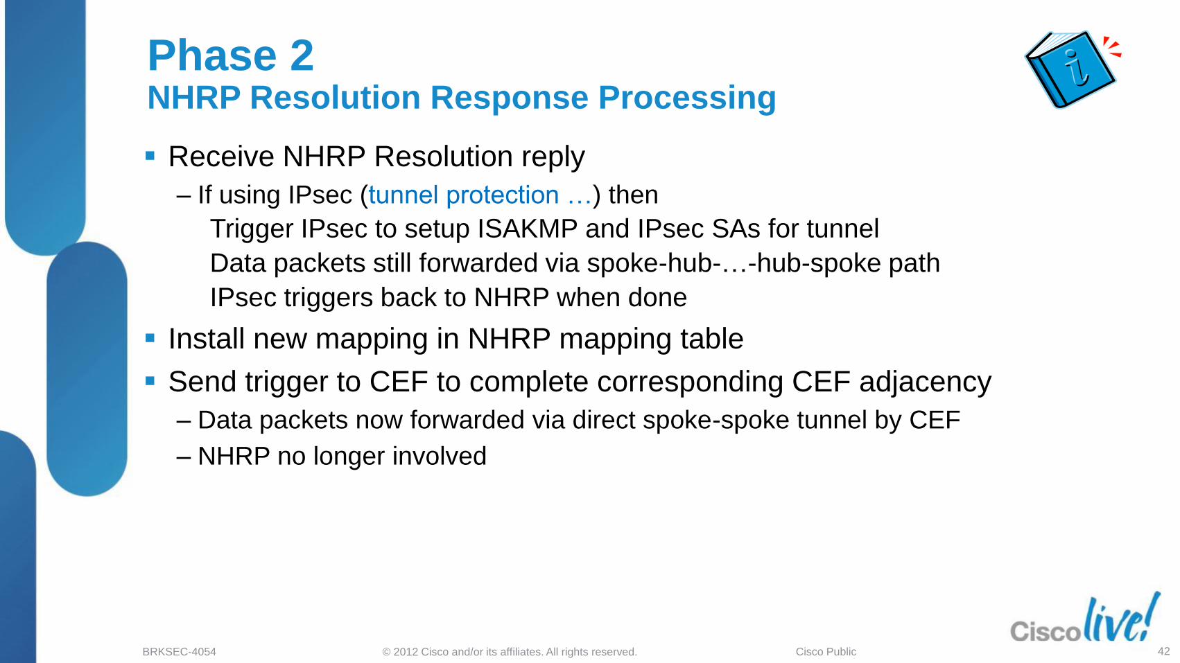
Phase 2NHRP Resolution Response Processing
Receive NHRP Resolution reply
‒ If using IPsec (tunnel protection …) then
Trigger IPsec to setup ISAKMP and IPsec SAs for tunnel
Data packets still forwarded via spoke-hub-…-hub-spoke path
IPsec triggers back to NHRP when done
Install new mapping in NHRP mapping table
Send trigger to CEF to complete corresponding CEF adjacency
‒ Data packets now forwarded via direct spoke-spoke tunnel by CEF
‒ NHRP no longer involved

© 2012 Cisco and/or its affiliates. All rights reserved.BRKSEC-4054 Cisco Public 43
Phase 2 – Dynamic mappingsRefresh or Remove
Dynamic NHRP mapping entries have finite lifetime
‒ Controlled by „ip nhrp holdtime …‟ on source of mapping (spoke)
Background process checks mapping entry every 60 seconds
‒ Process-switchingUsed flag set each time mapping entry is used
If used flag is set and expire time < 120 seconds, then refresh entry, otherwise clear used flag
‒ CEF-switchingIf expire time < 120 seconds, CEF Adjacency entry marked “stale”
If CEF Adjacency entry is used, signal to NHRP to refresh entry
Another resolution request is sent to refresh entry
‒ Resolution request via NHS path; reply via direct tunnel
If entry expires it is removed
‒ If using IPsec Trigger IPsec to remove IPsec/ISAKMP SAs

© 2012 Cisco and/or its affiliates. All rights reserved.BRKSEC-4054 Cisco Public 44
Phase 2 – CEF SwitchingData Packet Forwarding
IP Data packet is forwarded out tunnel interface to IP next-hopfrom CEF FIB table
If adjacency is of type Valid
‒ Packet is encapsulated and forwarded by CEF out tunnel interface
‒ NHRP is not involved
If adjacency is of type Glean or Incomplete
‒ Punt packet to process switching
‒ If original arriving interface was not this tunnel interface
Initiate NHRP Resolution Request for IP next-hop
Resolution reply is used to create NHRP mapping and to complete the Adjacency

© 2012 Cisco and/or its affiliates. All rights reserved.BRKSEC-4054 Cisco Public 45
Agenda
DMVPN Overview
NHRP Details
‒ NHRP Overview
‒ NHRP Registrations
‒ NHRP Resolutions/Redirects
Phase 2
Phase 3
Deployment Models
Recent and New Features

© 2012 Cisco and/or its affiliates. All rights reserved.BRKSEC-4054 Cisco Public 46
Phase 3 – Features
Used to increase scale of DMVPN networks
‒ Increase number of spokes, with same spoke/hub ratio
‒ Distribution hubs off load central hub
Manage local spoke-spoke tunnels
IP multicast and routing protocol
No hub daisy-chain
‒ Use routing and CEF switching to forward data and NHRP packets optimally through hubs
‒ Reduces complexity and load for routing protocol
OSPF routing protocol not limited to 2 hubs
‒ Network point-multipoint mode
‒ Still single OSPF area and no summarization
© 2012 Cisco and/or its affiliates. All rights reserved.BRKSEC-4054 Cisco Public 47
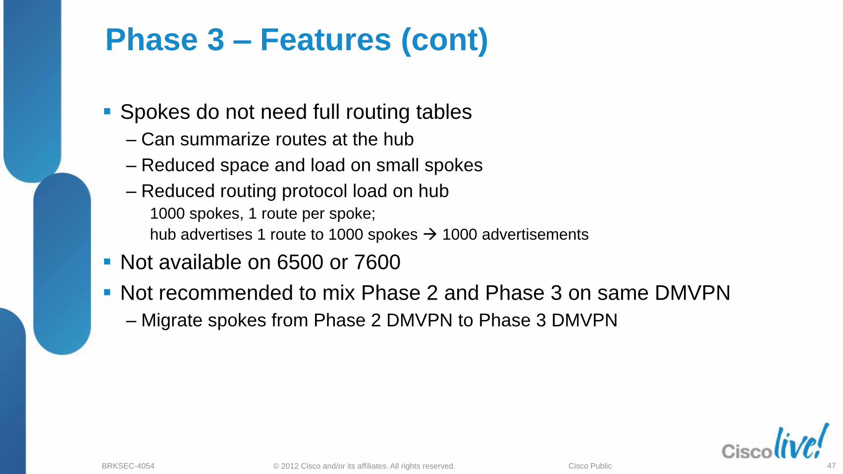
Phase 3 – Features (cont)
Spokes do not need full routing tables
‒ Can summarize routes at the hub
‒ Reduced space and load on small spokes
‒ Reduced routing protocol load on hub
1000 spokes, 1 route per spoke;
hub advertises 1 route to 1000 spokes 1000 advertisements
Not available on 6500 or 7600
Not recommended to mix Phase 2 and Phase 3 on same DMVPN
‒ Migrate spokes from Phase 2 DMVPN to Phase 3 DMVPN
© 2012 Cisco and/or its affiliates. All rights reserved.BRKSEC-4054 Cisco Public 48
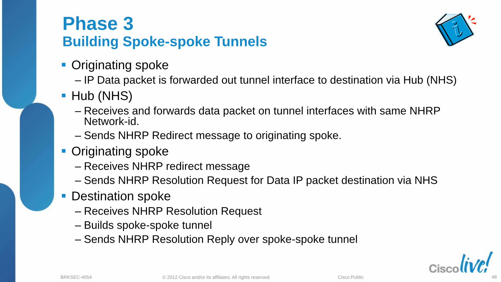
Originating spoke‒ IP Data packet is forwarded out tunnel interface to destination via Hub (NHS)
Hub (NHS)‒ Receives and forwards data packet on tunnel interfaces with same NHRP
Network-id.
‒ Sends NHRP Redirect message to originating spoke.
Originating spoke‒ Receives NHRP redirect message
‒ Sends NHRP Resolution Request for Data IP packet destination via NHS
Destination spoke‒ Receives NHRP Resolution Request
‒ Builds spoke-spoke tunnel
‒ Sends NHRP Resolution Reply over spoke-spoke tunnel
Phase 3Building Spoke-spoke Tunnels

© 2012 Cisco and/or its affiliates. All rights reserved.BRKSEC-4054 Cisco Public 49
Phase 3NHRP Redirects
Spoke1 Hubs Spoke2Host1 Host2
NHRP RedirectNHRP Redirect

© 2012 Cisco and/or its affiliates. All rights reserved.BRKSEC-4054 Cisco Public 50
Phase 3NHRP Redirects
Spoke A192.168.1.1/24
192.168.2.1/24
Physical: 172.17.0.1
Tunnel0: 10.0.0.1
Spoke B
Physical: (dynamic)
Tunnel0: 10.0.0.11
Physical: (dynamic)
Tunnel0: 10.0.0.12
10.0.0.11 172.16.1.110.0.0.12 172.16.2.1
192.168.0.1/24
192.168.1.0/24 10.0.0.11192.168.2.0/24 10.0.0.12
192.168.0.0/24 Conn.
CEF FIB Table
172.16.1.1
172.16.2.1
NHRP mapping
192.168.1.0/24 Conn.
10.0.0.1 172.17.0.1
192.168.2.0/24 Conn.
10.0.0.1 172.17.0.1
192.168.2.1 ???
192.168.0.0/16 10.0.0.1192.168.0.0/16 10.0.0.1
CEF Adjacency
10.0.0.1 172.17.0.1
10.0.0.11 172.16.1.1
Data packet
NHRP Redirect
NHRP Resolution
10.0.0.1 172.17.0.1
10.0.0.12 172.16.2.1

© 2012 Cisco and/or its affiliates. All rights reserved.BRKSEC-4054 Cisco Public 51
Phase 3NHRP Redirect Processing
Sender
‒ Insert (GRE IP header source, packet destination IP address) in NHRP redirect table – used to rate-limit NHRP redirect messages
‒ Send NHRP redirect to GRE/IP header source
‒ Time out rate-limit entries from the NHRP redirect table
Receiver
‒ Check data IP source address from data IP header in redirect
‒ If routing to the IP source is out:
• A GRE tunnel interface with the same NHRP Network-id then drop redirect
• Another interface, the IP destination is permitted by „ip nhrp interest <ACL>‟and „ip nhrp shortcut‟ is configured
Trigger an NHRP resolution request to IP destination
‒ Otherwise drop redirect

© 2012 Cisco and/or its affiliates. All rights reserved.BRKSEC-4054 Cisco Public 52
Phase 3NHRP Resolution Request
Spoke1 Hubs Spoke2Host1 Host2
NHRP Res. Request NHRP Res. Request
IKE Initialization
IKE Initialization
NHRP RedirectNHRP Redirect
NHRP Res. RequestNHRP Res. Request

© 2012 Cisco and/or its affiliates. All rights reserved.BRKSEC-4054 Cisco Public 53
Phase 3NHRP Resolution Request
Spoke A192.168.1.1/24
192.168.2.1/24
Physical: 172.17.0.1
Tunnel0: 10.0.0.1
Spoke B
Physical: (dynamic)
Tunnel0: 10.0.0.11
Physical: (dynamic)
Tunnel0: 10.0.0.12
10.0.0.11 172.16.1.110.0.0.12 172.16.2.1
192.168.0.1/24
192.168.1.0/24 10.0.0.11192.168.2.0/24 10.0.0.12
192.168.0.0/24 Conn.
CEF FIB Table
172.16.1.1
172.16.2.1
NHRP mapping
192.168.1.0/24 Conn.
10.0.0.1 172.17.0.1
192.168.2.0/24 Conn.
10.0.0.1 172.17.0.1
192.168.2.1 ???
192.168.0.0/16 10.0.0.1192.168.0.0/16 10.0.0.1
CEF Adjacency
10.0.0.1 172.17.0.110.0.0.11 172.16.1.1
10.0.0.11 172.16.1.1
10.0.0.11 172.16.1.1
Data packet
NHRP Redirect
NHRP Resolution
10.0.0.1 172.17.0.1
10.0.0.12 172.16.2.1
10.0.0.11 172.16.1.1

© 2012 Cisco and/or its affiliates. All rights reserved.BRKSEC-4054 Cisco Public 54
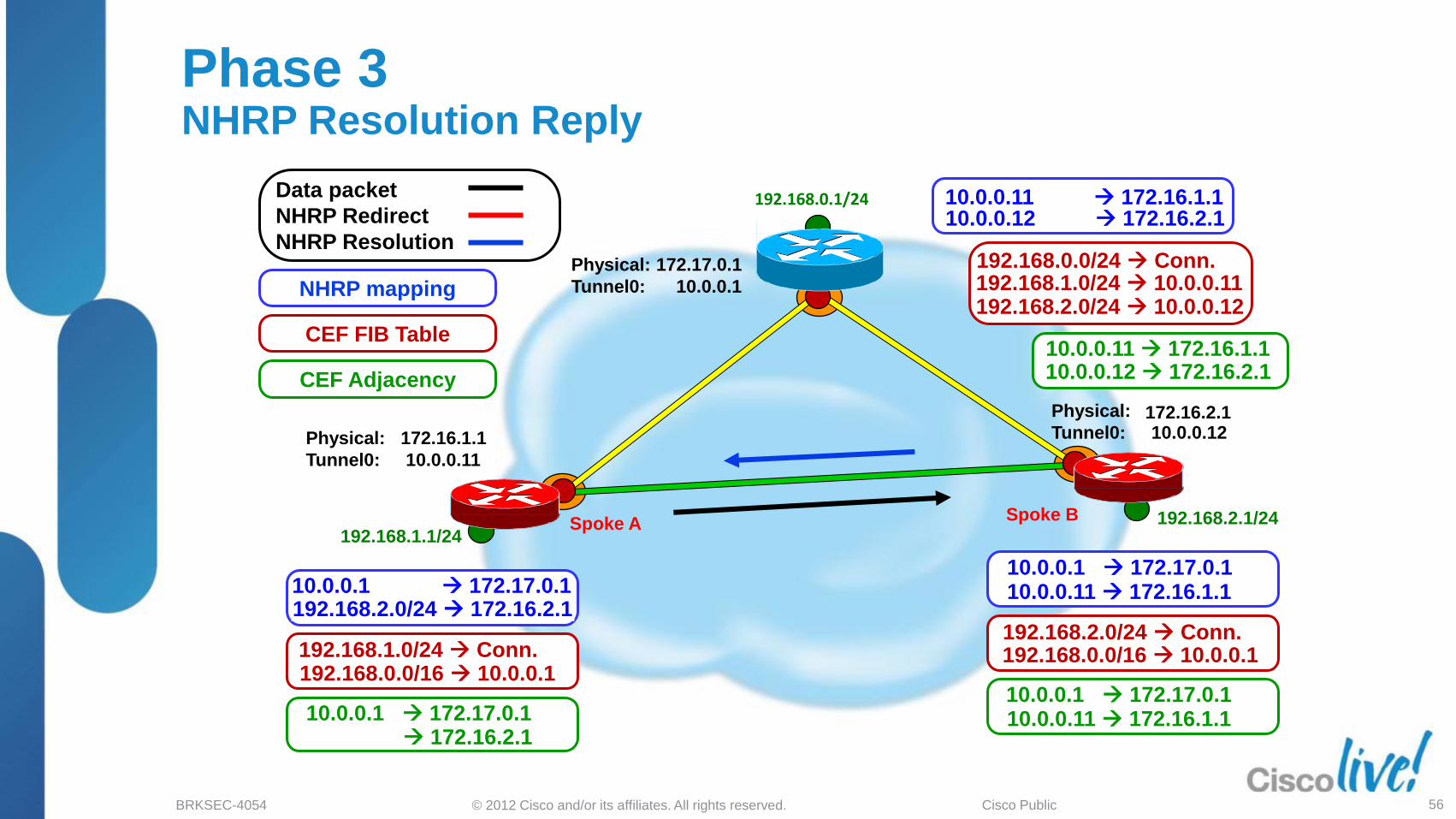
Spoke (NHC) routing table has Hub (NHS) as IP next-hop for networks behind remote Spoke
‒ If routing table has IP next-hop of remote spoke then process as in Phase 2
Data packets are forwarded (CEF-switched) via routed path
‒ Redirect message sent by every tunnel hop on routed path
‒ Redirect for data packet triggers resolution request only on source spoke
Send resolution request for IP destination from data packet header in redirect message
Resolution requests forwarded via routed path
Resolution replies forwarded over direct tunnel
‒ Direct tunnel initiated from remote local spoke
Forward data packets over direct tunnel after receipt of resolution reply.
Phase 3 NHRP Resolution Processing

© 2012 Cisco and/or its affiliates. All rights reserved.BRKSEC-4054 Cisco Public 55
Phase 3 NHRP Resolution Reply
Spoke1 Hubs Spoke2Host1 Host2
IKE/IPsec Established
NHRP Res. Request NHRP Res. Request
Encrypted
IKE Initialization
IKE Initialization
NHRP RedirectNHRP Redirect
NHRP Res. RequestNHRP Res. Request
NHRP Resolution Reply
© 2012 Cisco and/or its affiliates. All rights reserved.BRKSEC-4054 Cisco Public 56
Phase 3 NHRP Resolution Reply
Spoke A192.168.1.1/24
192.168.2.1/24
Physical: 172.17.0.1
Tunnel0: 10.0.0.1
Spoke B
Physical: (dynamic)
Tunnel0: 10.0.0.11
Physical: (dynamic)
Tunnel0: 10.0.0.12
10.0.0.11 172.16.1.110.0.0.12 172.16.2.1
192.168.0.1/24
192.168.1.0/24 10.0.0.11192.168.2.0/24 10.0.0.12
192.168.0.0/24 Conn.
CEF FIB Table
172.16.1.1
172.16.2.1
NHRP mapping
192.168.1.0/24 Conn.
10.0.0.1 172.17.0.110.0.0.1 172.17.0.1192.168.2.1 ???
192.168.0.0/16 10.0.0.1192.168.0.0/16 10.0.0.1
CEF Adjacency
10.0.0.1 172.17.0.1
172.16.2.1 10.0.0.11 172.16.1.1
10.0.0.11 172.16.1.1
192.168.2.0/24 172.16.2.110.0.0.11 172.16.1.1
Data packet
NHRP Redirect
NHRP Resolution
10.0.0.1 172.17.0.1
10.0.0.12 172.16.2.1
192.168.2.0/24 Conn.

© 2012 Cisco and/or its affiliates. All rights reserved.BRKSEC-4054 Cisco Public 57
IP Data packet is forwarded out tunnel interface
1. IP next-hop from CEF FIB mapped to AdjacencyIf adjacency is:
Glean or Incomplete Punt to process switching
Valid Select adjacency for the packet
2. NHRP in Outbound CEF Feature pathLook up packet IP destination in NHRP mapping table
Matching entry: Reselect adjacency use direct spoke-spoke tunnel
No matching entry: Leave CEF adjacency packet goes to hub
If packet arrived on and is forwarded out the same tunnel interface
‒ Forward data packet
‒ If „ip nhrp redirect‟ is on inbound tunnel then send NHRP redirect
Packet is encapsulated, encrypted and forwarded
Phase 3 – CEF SwitchingData Packet Forwarding (Current – ISR, 7200)

© 2012 Cisco and/or its affiliates. All rights reserved.BRKSEC-4054 Cisco Public 58
Phase 3 – NHRP and Routing TableData Packet Forwarding (ASR1k; 15.2(1)T – ISR, 7200)
When NHRP resolution is received
‒ Insert mapping information in mapping table replacing Incomplete/Temporary mapping
‒ Insert NHRP routing entry in Routing Table (RT)
NHRP NET/Mask is more specific than RT Net/Mask
Add new route owned by NHRP (Type = H)
Monitor parent route
If parent route changes outbound interface then remove NHRP route.
NHRP Net/Mask is equal to RT Net/Mask
Add Override Alternate Next-hop (% flag)
Route still owned by original owner
NHRP Net/Mask is less specific than RT Net/Mask
Reduce NHRP mask to = RT Mask
Add Override Alternate Next-hop (% flag)
Route still owned by original owner

© 2012 Cisco and/or its affiliates. All rights reserved.BRKSEC-4054 Cisco Public 59
Phase 3 – NHRP and RTRouting Table (ASR1k; 15.2(1)T – ISR, 7200)
Routing entry for 192.168.128.0/24Known via "eigrp 1", distance 90, metric 3200000, type internalRedistributing via eigrp 1Last update from 10.0.2.16 on Tunnel0, 00:43:44 agoRouting Descriptor Blocks:* 10.0.2.16, from 10.0.2.16, 00:43:44 ago, via Tunnel0
Route metric is 3200000, traffic share count is 1…
#show ip route next-hop-override | section H|%
D 192.168.128.0/24 [90/3200000] via 10.0.2.16, 00:50:56, Tunnel0
#show ip route
D 192.168.128.0/24 [90/3200000] via 10.0.2.16, 00:50:56, Tunnel0
EIGRPRoutes
NHRPRoutes
Next-Hop-Override
Entries
H 192.168.11.0/24 [250/1] via 10.0.1.11, 00:01:02
H 192.168.11.0/24 [250/1] via 10.0.1.11, 00:01:02
Routing entry for 192.168.11.0/24Known via "nhrp", distance 250, metric 1Last update from 10.0.1.11 00:05:29 agoRouting Descriptor Blocks:* 10.0.1.11, from 10.0.1.11, 00:05:29 ago
Route metric is 1, traffic share count is 1
H 192.168.11.0/24 [250/1] via 10.0.1.11, 00:01:02
H 192.168.11.0/24 [250/1] via 10.0.1.11, 00:01:02
Routing entry for 192.168.11.0/24Known via "nhrp", distance 250, metric 1Last update from 10.0.1.11 00:05:29 agoRouting Descriptor Blocks:* 10.0.1.11, from 10.0.1.11, 00:05:29 ago
Route metric is 1, traffic share count is 1
%
%[NHO][90/1] via 10.0.0.1, 00:00:40, Tunnel0
[NHO]10.0.0.1, from 10.0.0.1, 00:05:57 ago, via Tunnel0Route metric is 1, traffic share count is 1
…
%
%[NHO][90/1] via 10.0.0.1, 00:00:40, Tunnel0
[NHO]10.0.0.1, from 10.0.0.1, 00:05:57 ago, via Tunnel0Route metric is 1, traffic share count is 1
…

© 2012 Cisco and/or its affiliates. All rights reserved.BRKSEC-4054 Cisco Public 60
Phase 3 – Dynamic MappingsRefresh or Remove
Dynamic NHRP mapping entries have finite lifetime‒ Controlled by „ip nhrp holdtime …‟ on source of mapping (spoke)
‒ Two types of mapping entriesMaster entry – Remote Spoke Tunnel IP addressChild entries – Remote Network address(es)
Background process checks mapping entries every 60 seconds‒ Child entry: Marked used and timing out refresh Child entry
‒ Master entry: Timing out mark CEF adjacency staleIf CEF adjacency is used refresh Master entry
Refreshing entries‒ Send another Resolution request and reply
Resolution request/reply sent over direct tunnel
If entry expires it is removed‒ If using IPsec and last entry using NBMA address
Trigger IPsec to remove IPsec and ISAKMP SAs

© 2012 Cisco and/or its affiliates. All rights reserved.BRKSEC-4054 Cisco Public 61
Used to clear invalid NHRP mapping information from the network
NHRP “local” mapping entries
‒ Created when sending an NHRP resolution reply
‒ Copy of mapping information sent in reply
‒ Entry tied to corresponding entry in routing table
‒ Keeps list of nodes where resolution reply was sent
To see use „show ip nhrp detail‟
If routing table changes so that local mapping entry is no longer valid
‒ Purge message is sent to each NHRP node in list
‒ NHRP nodes clear that mapping from their table
‒ Purge messages forwarded over direct tunnel if available, otherwise sent via routed path
NHRP Purge Messages

Deployment Models

© 2012 Cisco and/or its affiliates. All rights reserved.BRKSEC-4054 Cisco Public 63
Agenda
DMVPN Overview
NHRP Details
Deployment Models
‒ Basic Network Designs
‒ Routing Protocol considerations
‒ Scaling DMVPN nodes
Recent and New Features

© 2012 Cisco and/or its affiliates. All rights reserved.BRKSEC-4054 Cisco Public 64
Basic Network Designs
Hub-and-spoke – Order(n)
‒ Spoke-to-spoke traffic via hub
Phase 1: Hub bandwidth and CPU limit VPN
SLB: Many “identical” hubs increase CPU limit
Spoke-to-spoke – Order(n) « Order(n2)
‒ Control traffic; Hub and spoke; Hub to hub
Phase 2: (single)
Phase 3: (hierarchical)
‒ Unicast Data traffic; Dynamic mesh
Spoke routers support spoke-hub and spoke-spoke tunnels currently in use.
Hub supports spoke-hub traffic and overflow from spoke-spoke traffic.
Network Virtualization‒ VRF-lite; Multiple DMVPNs
‒ MPLS over DMVPN (2547oDMVPN); Single DMVPN

© 2012 Cisco and/or its affiliates. All rights reserved.BRKSEC-4054 Cisco Public 65
Basic DMVPN Designs
Single DMVPN Dual HubSingle mGRE tunnel on all nodes
= Dynamic Spoke-to-spoke
192.168.2.0/24
.1
192.168.1.0/24
.1
192.168.0.0/24.2 .1
Physical: 172.17.0.1
Tunnel0: 10.0.0.1
Physical: (dynamic)
Tunnel0: 10.0.0.11
Physical: (dynamic)
Tunnel0: 10.0.0.12
Physical: 172.17.0.5
Tunnel0: 10.0.0.2
Spoke A
Spoke B
. . .
Dual DMVPN Single HubSingle tunnel on Hub, two on spokes
192.168.1.0 /24
192.168.2.0/24
192.168.0.0/24.2 .1
Spoke A
Spoke B
Physical: 172.17.0.1
Tunnel0: 10.0.0.1Physical: 172.17.0.5
Tunnel0: 10.0.1.1
Physical: (dynamic)
Tunnel0: 10.0.0.11
Tunnel1: 10.0.1.11
Physical: (dynamic)
Tunnel0: 10.0.0.12
Tunnel1: 10.0.1.12
.1
.1

© 2012 Cisco and/or its affiliates. All rights reserved.BRKSEC-4054 Cisco Public 66
Multiple DMVPNs versus Single DMVPN
Multiple DMVPNs
‒ Best for Hub-and-spoke only
Easier to manipulate RP metrics between DMVPNs for Load-sharing
EIGRP – Delay on tunnel, BGP – Communities; OSPF – Cost
Performance Routing (PfR) selects between interfaces
‒ Load-balancing over multiple ISPs (physical paths)Load-balance data flows over tunnels Better statistical balancing
Single DMVPN
‒ Best for spoke-spoke DMVPN
Can only build spoke-spoke within a DMVPN not between DMVPNs
More difficult to manipulate RP metrics within DMVPN for Load-sharing
EIGRP – Route tagging; BGP – Communities; OSPF – Can‟t do
‒ Load-balancing over multiple ISPs (physical paths)Load-balance tunnel destinations or physical Worse statistical balancing

© 2012 Cisco and/or its affiliates. All rights reserved.BRKSEC-4054 Cisco Public 67
DMVPN Combination Designs
Spoke-to-hub tunnels
Spoke-to-spoke tunnels
Retail/Franchise
Spoke-to-hub tunnels
Spoke-to-spoke tunnels
Spoke-hub-hub-spoke tunnel
Dual ISP
ISP 2ISP 1

© 2012 Cisco and/or its affiliates. All rights reserved.BRKSEC-4054 Cisco Public 68
DMVPN Combination Designs (cont)
Spoke-to-hub tunnelsSpoke-to-spoke tunnelsHub-to-hub tunnel
Server Load Balancing
Spoke-to-hub tunnels
Spoke-to-spoke tunnels
Hierarchical
© 2012 Cisco and/or its affiliates. All rights reserved.BRKSEC-4054 Cisco Public 69
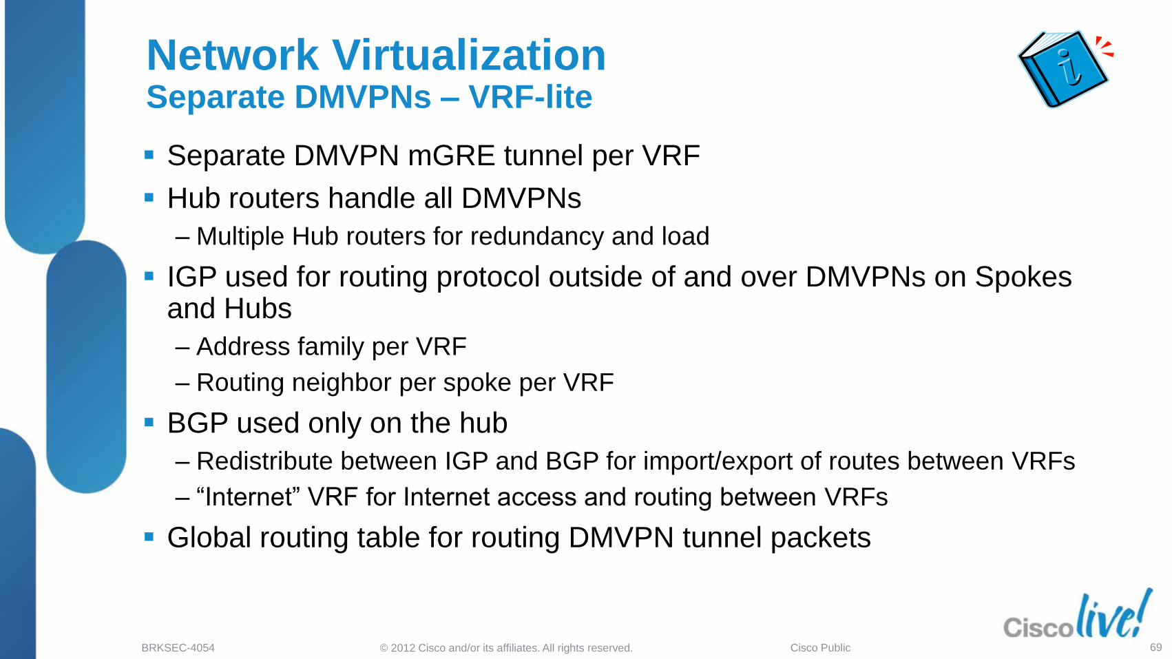
Separate DMVPN mGRE tunnel per VRF
Hub routers handle all DMVPNs
‒ Multiple Hub routers for redundancy and load
IGP used for routing protocol outside of and over DMVPNs on Spokes and Hubs
‒ Address family per VRF
‒ Routing neighbor per spoke per VRF
BGP used only on the hub
‒ Redistribute between IGP and BGP for import/export of routes between VRFs
‒ “Internet” VRF for Internet access and routing between VRFs
Global routing table for routing DMVPN tunnel packets
Network VirtualizationSeparate DMVPNs – VRF-lite

© 2012 Cisco and/or its affiliates. All rights reserved.BRKSEC-4054 Cisco Public 70
Single DMVPN (Hub-and-spoke Only)
‒ MPLS VPN over DMVPN
‒ Single mGRE tunnel on all routers
MPLS configuration
‒ Hub and Spoke routers are MPLS PEs
Multiple Hub routers for redundancy and load
IGP is used for routing outside of DMVPN network
BGP used for routing protocol over DMVPN
‒ Redistribute between IGP and BGP for transport over DMVPN
‒ Import/export of routes between VRFs and Global (or Internet VRF)
‒ One routing neighbor per spoke
Global routing table for routing DMVPN tunnel packets
Network VirtualizationMPLS over DMVPN – 2547oDMVPN

© 2012 Cisco and/or its affiliates. All rights reserved.BRKSEC-4054 Cisco Public 71
DMVPN Network Virtualization Designs
2547oDMVPN
VRF-A tunnelsVRF-B tunnelsVRF-A to VRF-B Path (optional)
VRF-lite
VRF-A tunnelsVRF-B tunnelsVRF-A/B Tunnels

Design Selection

© 2012 Cisco and/or its affiliates. All rights reserved.BRKSEC-4054 Cisco Public 73
Network Designs Common Requirements
Small/Medium Business
‒ DMVPN Phase 3 single layer design
‒ Dial backup and VRF for non-split-tunneling
‒ Up to 1000 spokes, with dynamic spoke-spoke tunnels.
Larger Business
‒ DMVPN Phase 3 hierarchical layer design
‒ Dial backup, multiple ISP connections, VRF for non-split-tunneling,VRF and 2547oDMVPN for group separation.
‒ 1000-4000+ spokes, with dynamic spoke-spoke tunnels.
Home Office - Work Access
‒ CVO (Cisco Virtual Office) designs
‒ DMVPN Phase 3 single layer design
‒ 1000s of spokes

© 2012 Cisco and/or its affiliates. All rights reserved.BRKSEC-4054 Cisco Public 74
Network Designs Common Requirements (cont.)
Point-of-Sale / ATM
‒ Server Load Balancing (SLB) designs – Super Hub
‒ No spoke-spoke (designs now available to enable spoke-spoke)
‒ 4000-20000+ spokes.
Extranet
‒ DMVPN Phase 1 Hub-and-spoke design
‒ No spoke-spoke not even via the Hub – (using ACLs)
‒ Probably <1000 spokes.
ISP
‒ DMVPN Phase 3 or SLB designs, MPLS (2547oDMVPN), VRFs
‒ Hub-and-spoke and spoke-spoke networks.
‒ Different size networks (# of spokes), but also supporting multiple DMVPNs on the same set of hub routers.

© 2012 Cisco and/or its affiliates. All rights reserved.BRKSEC-4054 Cisco Public 75
Design Selection Challenge
Routing protocol characteristics and scalability is different
More than one design can satisfy a given set of requirements
Addition of certain features change the design or topology e.g. multicast
Wide variety of platforms and encryption modules to choose for the Hub
Certain platforms or IOS trains do not support all the features

© 2012 Cisco and/or its affiliates. All rights reserved.BRKSEC-4054 Cisco Public 76
Solution – Common Design Selection Criteria
Encryption
Throughput?
VSA, ISM, ESP5-40
Topology?
Hub & Spoke or
Spoke to Spoke
Fine tune
Modify design
based on platform
and IOS
Routing Protocol?
EIGRP, BGP, OSPF,
RIP
Routing over the tunnel
Step 4:Adjust DMVPN phase
or topology based on
IOS, platform or traffic
requirements
Step 1:Select topology
based on
requirement
Step 2:Select RP based on
scalability OR scale
design based on
selected RP
Step 3:Select platform,
encryption card
based on throughput
requirements

© 2012 Cisco and/or its affiliates. All rights reserved.BRKSEC-4054 Cisco Public 77
Step 1 – Select Topology
Spokes connect to two or more hubs for resiliency (2n)
Based on routing, traffic can be distributed over both
hubs OR prefer a single hub
More complicated to manipulate routing metrics
Resilient Spoke to Spoke (Phase 2 or 3)
Spokes connect to two or more hubs for resiliency (2n)
Based on routing, traffic can be distributed to both hubs
OR can always be sent to a primary hub
Easier to manipulate routing metrics
Resilient Hub and Spoke (Phase 1)

© 2012 Cisco and/or its affiliates. All rights reserved.BRKSEC-4054 Cisco Public 78
Step 1 – Select Topology (cont)
Spokes are configured to connect to SLB virtual address
Generally hub-and-spoke only, spoke-spoke optional
SLB automatically load-balances across up hubs (n+(1,2))
Two SLBs for further redundancy (2n)
Server Load Balancing (Phase 1 or 3)
Spokes connect to Regional Hub(s);Regional Hubs connect to Central Hub(s)
Spokes can build spoke-spoke within region (blue)or optionally to any node in the network (green)
Multiple hubs in regions and central site for resiliency
Hierarchical (Phase 3)

© 2012 Cisco and/or its affiliates. All rights reserved.BRKSEC-4054 Cisco Public 79
Step 2 – Either Select a Routing Protocol based on Scalability requirements
EIGRP
SLB design using BGP, EIGRP or RIPv2 Passive
OSPF
ASR-RP2(ESP20+)(XE 3.4)3945E
ASR-RP2BGP 7200
3945E
ASR7200
ASR-RP2(ESP20+)(XE 3.4)3945E7200
ASR-RP2
Estimate: More testing is needed for OSPF
4000 spoke routes total: 4000 spokes with 1 route/spoke
or 800 spokes with 5 routes/spoke
Number of Branches 40001000 2000 3000

© 2012 Cisco and/or its affiliates. All rights reserved.BRKSEC-4054 Cisco Public 80
Step 2 – OR Scale preferred Routing Protocol
BGP
3945E
RIPv2
EIGRP
ASR-RP2-ESP20+(XE3.4)4000 spoke routes total
3945E
ASR-RP2-ESP20+(XE3.4)3945E
ASR/RP27200
Number of Branches 40001000 2000 3000
7200
ASR-RP2
7200
ASR-RP2
Deploy N DMVPN clouds to scale single cloud N times
Use Hierarchical DMVPN design
Use SLB design to scale RP using N number of hubs

© 2012 Cisco and/or its affiliates. All rights reserved.BRKSEC-4054 Cisco Public 81
Step 3 – Select Platform andEncryption Module
IMIX Encryption
Throughput at
70% Max CPU7200 VAM2+
7200 G2/VSA
SLB Design
ASR1001/RP2/Integrated
8.0 G125 M 250 M 500 M 1.0 G 4.0 G2.0 G
3945E
ASR1002+/RP2/ESP10
ASR1004+/RP2/ESP20
ASR1006+/RP2/ESP40
Throughput depends on
number and types of hub
platforms

© 2012 Cisco and/or its affiliates. All rights reserved.BRKSEC-4054 Cisco Public 82
Step 4 – Final Design Adjustment
Spoke to spoke design works differently depending on code release
Hub and Spoke design works the same in mainline or T train.
Select a stable well tested release.
Spoke to spoke traffic (if allowed) will traverse the hub.
DMVPN Phase 2
Hubs need to be daisy chained
Can not summarize routes
Next hop must be unchanged
OSPF can not support more than two hubs
12.4M, pre 12.4(6)T, ASR (Rel. 2) or later
7200,ISR, ASR1000 as a hub or spoke
DMVPN Phase 3
No daisy chain required
Route summarization possible
NHRP Redirect and shortcut
Hierarchical designs for better scalability
12.4(6)T or later, ASR (Rel. 5) or later
7200,ISR, ASR1000 as a hub or spoke
IP MulticastUses dramatically more bandwidth on Hubs (Ex: 128Kb/s (stream) x 1000 (spokes) = 128 Mb/s)
Will create packet bursts of up to 300 Mb/s effective rate – may overwhelm Encryptor input queues,
interface or system buffers. May need to increase queue and buffer sizes.

© 2012 Cisco and/or its affiliates. All rights reserved.BRKSEC-4054 Cisco Public 83
Cisco IOS Code and Platform Support
7200(G1), 3800, 2800, 1800, 880
‒ Phase 1 & 2 only: 12.4(25f); Phase 1, 2 & 3: 12.4(15)T17, 12.4(24)T7
6500/7600 with VPN-SPA+sup720 – No Phase 3 capability
‒ 6500: 12.2(33)SXJ1;
‒ 7600: 12.2(33)SRE6, 15.2(2)S
7200(G2) with VSA
‒ 12.4(24)T7, 15.1(4)M4
ISR-G2 (3900(E), 2900, 1900, 890)
‒ 15.1(4)M4, 15.1(3)T3, 15.2(3)T
ASR1000 (RP2)
‒ 15.1(3)S3, 15.2(1)S2

Recent and New Features

© 2012 Cisco and/or its affiliates. All rights reserved.BRKSEC-4054 Cisco Public 85
Agenda
DMVPN Overview
NHRP Details
Deployment Models
Recent and New Features
‒ IKEv2 with DMVPN
‒ Tunnel Health Monitoring
‒ Backup and FQDN NHS
‒ DHCP over DMVPN
‒ DMVPN IPv6 Transport

© 2012 Cisco and/or its affiliates. All rights reserved.BRKSEC-4054 Cisco Public 86
DMVPN can work with ISAKMP (IKEv1) and/or IKEv2
‒ Transparent to DMVPN
‒ Node can be responder for both ISAKMP and IKEv2
Both ISAKMP and IKEv2 are configured.
‒ Node can be Initiator for either ISAKMP or IKEv2 not both
Configure under the „crypto ipsec profile ...‟
IKEv2 with DMPVN
crypto isakmp policy 2encr aesauthentication pre-sharegroup 2
crypto ikev2 keyring DMVPNpeer DMVPN
address 0.0.0.0 0.0.0.0pre-shared-key cisco123
crypto ikev2 profile DMVPNmatch identity remote address 0.0.0.0 authentication local pre-shareauthentication remote pre-sharekeyring DMVPN
crypto isakmp key cisco123 address 0.0.0.0 0.0.0.0
crypto ipsec transform-set DMVPN esp-aes esp-sha-hmacmode transport [require]
crypto ipsec profile DMVPNset transform-set DMVPN set ikev2-profile DMVPN
interface Tunnel0...tunnel protection ipsec profile DMVPN

© 2012 Cisco and/or its affiliates. All rights reserved.BRKSEC-4054 Cisco Public 87
Issue
‒ mGRE tunnel Interface is always “up”
‒ Can‟t use standard backup/recovery mechanisms
backup interface, static interface routes, …
Solution
‒ New Command „if-state nhrp‟
‒ Monitor NHRP registration replies
If all NHSs are “down” then set tunnel interface up/down
Continue to send NHRP registration requests
If a single NHS is “up” then set tunnel interface up/up
Tunnel Health MonitoringInterface State – 15.0(1)M
interface Tunnel0ip address 10.0.0.11 255.255.255.0…ip nhrp map multicast 172.17.0.1ip nhrp map 10.0.0.1 172.17.0.1ip nhrp map multicast 172.17.0.5ip nhrp map 10.0.0.2 172.17.0.5…ip nhrp nhs 10.0.0.1ip nhrp nhs 10.0.0.2…if-state nhrp…

© 2012 Cisco and/or its affiliates. All rights reserved.BRKSEC-4054 Cisco Public 88
Tunnel Health MonitoringInterface State (cont)
#show ip nhrp nhs detail10.0.0.1 RE req-sent 100 req-failed 0 repl-recv 90 (00:01:38 ago)10.0.0.2 RE req-sent 125 req-failed 0 repl-recv 79 (00:01:38 ago)
#show interface tunnel0Tunnel0 is up, line protocol is up
*Apr 19 21:32:52 NHRP: NHS-DOWN: 10.0.0.1*Apr 19 21:32:52 NHRP: NHS 10.0.0.1 Tunnel0 vrf 0 Cluster 0 Priority 0 Transitioned to 'E' from 'RE' *Apr 19 21:32:53 NHRP: NHS-DOWN: 10.0.0.2*Apr 19 21:32:53 NHRP: NHS 10.0.0.2 Tunnel0 vrf 0 Cluster 0 Priority 0 Transitioned to 'E' from 'RE'
*Apr 19 21:33:02 %LINEPROTO-5-UPDOWN: Line protocol on Interface Tunnel0, changed state to down*Apr 19 21:33:02 NHRP: if_down: Tunnel0 proto IPv4
#show ip nhrp nhs detail10.0.0.1 E req-sent 105 req-failed 0 repl-recv 90 (00:02:12 ago)10.0.0.2 E req-sent 130 req-failed 0 repl-recv 79 (00:02:12 ago)
#show interface tunnel0Tunnel0 is up, line protocol is down
*Apr 19 21:33:12 NHRP: Send Registration Request via Tunnel0 vrf 0, packet size: 92*Apr 19 21:33:13 NHRP: Send Registration Request via Tunnel0 vrf 0, packet size: 92…*Apr 19 21:34:36 NHRP: NHS 10.0.0.1 Tunnel0 vrf 0 Cluster 0 Priority 0 Transitioned to 'RE' from 'E' *Apr 19 21:34:36 NHRP: NHS-UP: 10.0.0.1*Apr 19 21:34:42 %LINEPROTO-5-UPDOWN: Line protocol on Interface Tunnel0, changed state to up*Apr 19 21:34:42 NHRP: if_up: Tunnel0 proto 0
#show ip nhrp nhs detail10.0.0.1 RE req-sent 110 req-failed 0 repl-recv 96 (00:00:19 ago)10.0.0.2 E req-sent 135 req-failed 0 repl-recv 79 (00:04:09 ago)
#show interface tunnel0Tunnel0 is up, line protocol is up

© 2012 Cisco and/or its affiliates. All rights reserved.BRKSEC-4054 Cisco Public 89
Backup and FQDN NHS – 15.1(2)T
Issue
‒ Backup NHSs only needed when primary NHSs are down
‒ Backup NHSs can be over subscribed
Solution
‒ Set NHS „max-connections‟
Can set NHS priority (default=0 (best)) – Can have multiple hubs at the same priority
Can group NHSs into clusters (default=0) – Separate max-connection value per cluster
Configuration reduction – Single line NHS configuration and FQDN NHS
‒ Functionality
NHSs are brought up in priority order, until cluster max-connections
Down NHS at same priority is probed if not at max-connections
Down NHS at a lower priority than an active NHS is probedeven when max-connections is reached
FQDN resolved when bringing up NHS

© 2012 Cisco and/or its affiliates. All rights reserved.BRKSEC-4054 Cisco Public 90
Backup and FQDN NHS (cont)
interface Tunnel0…ip nhrp nhs 10.0.0.1 nbma Hub1.cisco.com multicast priority 10 cluster 1ip nhrp nhs 10.0.0.2 nbma 172.17.0.5 multicast priority 20 cluster 1ip nhrp nhs 10.0.0.3 nbma 172.17.0.9 multicast priority 10 cluster 2ip nhrp nhs 10.0.0.4 nbma 172.17.0.13 multicast priority 10 cluster 2ip nhrp nhs cluster 1 max-connections 1ip nhrp nhs cluster 2 max-connections 1
#show ip nhrp nhsLegend: E=Expecting replies, R=Responding, W=WaitingTunnel0:10.0.0.1 RE NBMA Address: 172.17.0.1 (Hub1.Cisco.com) priority = 10 cluster = 110.0.0.2 W NBMA Address: 172.17.0.5 priority = 20 cluster = 110.0.0.3 RE NBMA Address: 172.17.0.9 priority = 10 cluster = 210.0.0.4 W NBMA Address: 172.17.0.13 priority = 10 cluster = 2
interface Tunnel0…ip nhrp map 10.0.0.1 172.17.0.1ip nhrp map multicast 172.17.0.1ip nhrp map 10.0.0.2 172.17.0.5ip nhrp map multicast 172.17.0.5ip nhrp map 10.0.0.3 172.17.0.9ip nhrp map multicast 172.17.0.9ip nhrp map 10.0.0.4 172.17.0.13ip nhrp map multicast 172.17.0.13…ip nhrp nhs 10.0.0.1ip nhrp nhs 10.0.0.2ip nhrp nhs 10.0.0.3ip nhrp nhs 10.0.0.4ip nhrp nhs cluster 0 max-connections 2…
#show ip nhrp10.0.0.1/32 via 10.0.0.1 Tunnel0 Type: static, Flags: used
NBMA address: 172.17.0.1 10.0.0.2/32 via 10.0.0.2 Tunnel0 Type: static, Flags: used
NBMA address: 172.17.0.510.0.0.3/32 via 10.0.0.3 Tunnel0 Type: static, Flags: used
NBMA address: 172.17.0.9 (no-socket) 10.0.0.4/32 via 10.0.0.4 Tunnel0 Type: static, Flags: used
NBMA address: 172.17.0.13 (no-socket)
#show ip nhrp nhsLegend: E=Expecting replies, R=Responding, W=WaitingTunnel0:10.0.0.1 RE priority = 0 cluster = 010.0.0.2 RE priority = 0 cluster = 010.0.0.3 W priority = 0 cluster = 010.0.0.4 W priority = 0 cluster = 0

© 2012 Cisco and/or its affiliates. All rights reserved.BRKSEC-4054 Cisco Public 91
DHCP over DMVPN – 15.1(3)T
Issue
‒ Must pre-configure tunnel interface IP Address and Subnet on Spokes
Solution
‒ Use DHCP to allocate Spoke‟s Tunnel IP Address/Subnetip address dhcp
ip dhcp client broadcast-flag clear
‒ Hub is DHCP Relay AgentGlobal
ip dhcp support tunnel unicast
Tunnel Interface
ip helper-address <ip-dhcp-server>
‒ FunctionalityDHCP request broadcast to all NHSs, replies unicast back to Spoke
Sticky until tunnel interface goes down

© 2012 Cisco and/or its affiliates. All rights reserved.BRKSEC-4054 Cisco Public 92
DHCP and FQDN NHSExample:
Spoke:
interface Tunnel0ip dhcp client broadcast-flag clearip address dhcp…ip nhrp network-id 100000…ip nhrp nhs dynamic nbma Hub1-NBMA multicast…ip nhrp shortcuttunnel source Serial1/0tunnel key 100000tunnel protection ipsec profile vpnprof
Hub:
ip dhcp support tunnel unicast!interface Tunnel0
ip address 10.0.0.1 255.255.255.0ip helper-address 192.168.0.3…ip nhrp map multicast dynamicip nhrp network-id 100000ip nhrp redirecttunnel source Serial2/0tunnel key 100000tunnel protection ipsec profile vpnprof
DHCP:
22:52:32.658: DHCP: Starting DHCP discover on Tunnel022:52:32.658: DHCP: SDiscover attempt # 1 for entry:22:52:32.658: Hostname: Spoke1, B'cast on Tunnel0 interface from 0.0.0.0
22:52:32.738: DHCP: Offer Message, Offered Address: 10.0.0.1322:52:32.738: DHCP: Lease secs: 86400, Renewal secs: 43200, Rebind secs: 75600
22:52:32.738: DHCP: SRequest attempt # 1 for entry:22:52:32.738: Temp IP addr: 10.0.0.13 for peer on Interface: Tunnel022:52:32.738: Temp sub net mask: 255.255.255.022:52:32.738: Hostname: Spoke1, B'cast on Tunnel0 interface from 0.0.0.0
22:52:32.818: DHCP: Ack Message Offered Address: 10.0.0.1322:52:32.818: DHCP: Lease secs: 86400, Renewal secs: 43200, Rebind secs: 7560022:52:32.818: DHCP: Host Name Option: Spoke1.cisco-test.com

© 2012 Cisco and/or its affiliates. All rights reserved.BRKSEC-4054 Cisco Public 93
NHRP:
22:52:32.242: NHRP: Resolved FQDN Hub1-NBMA to 172.17.0.122:52:32.242: NHRP: Supressing registration requests (Tunnel0) has invalid address
. . .22:52:32.818: NHRP: Send Registration Request via Tunnel0 vrf 0, packet size: 10422:52:32.818: src NBMA: 172.16.1.1, src proto: 10.0.0.13, dst proto: 10.0.0.1322:52:32.818: NAT address Extension(9): client NBMA: 172.17.0.1, client protocol: 10.0.0.13
. . .22:52:32.870: NHRP: Receive Registration Reply via Tunnel0 vrf 0, packet size: 12422:52:32.870: src NBMA: 172.16.1.1, src proto: 10.0.0.13, dst proto: 10.0.0.122:52:32.870: Responder Address Extension(3): client NBMA: 172.17.0.1, client protocol: 10.0.0.122:52:32.870: NAT address Extension(9): client NBMA: 172.17.0.1, client protocol: 10.0.0.1
22:52:32.870: NHRP: Tu0: Creating nhs mapping for 10.0.0.1/32 NBMA: 172.17.0.122:52:32.870: NHRP: Tunnel0: Cache add for target 10.0.0.1/32 next-hop 10.0.0.1, 172.17.0.1
22:52:32.870: NHRP: Adding Tunnel Endpoints (VPN: 10.0.0.1, NBMA: 172.17.0.1)
Tunnel:
22:52:29.618: %LINK-3-UPDOWN: Interface Tunnel0, changed state to up22:52:29.622: %LINEPROTO-5-UPDOWN: Line protocol on Interface Tunnel0, changed state to up
. . .22:52:32.870: Tunnel0: Linking endpoint 10.0.0.1/172.17.0.122:52:32.870: FIBtunnel: Tu0:TED: Adding adj for 10.0.0.1, conn_id 022:52:32.870: FIBtunnel: Tu0: stacking IP 10.0.0.1 to Default:172.17.0.1
. . .22:52:32.902: %DUAL-5-NBRCHANGE: EIGRP-IPv4 1: Neighbor 10.0.0.1 (Tunnel0) is up: new adjacency
DHCP and FQDN NHSExample: (cont)

© 2012 Cisco and/or its affiliates. All rights reserved.BRKSEC-4054 Cisco Public 94
DMVPN over IPv6 Transport – 15.2(1)T
IPv6 and IPv4 packets over DMVPN IPv6 tunnels‒ Introduced in IOS release 15.2(1)T‒ IPv6 infrastructure network‒ IPv6 and/or IPv4 data packets over same IPv6 GRE tunnel‒ NHRP modifies Routing Table – like on ASR1k routers
Can run both DMVPN IPv4 and DMVPN IPv6‒ Separate DMVPNs (mGRE tunnel interfaces)‒ DMVPN IPv4 DMVPN IPv6 spoke to spoke via hub
Configuration‒ Standard IPv6 configuration on Outside (WAN) interface‒ Small change on mGRE tunnel interface‒ Must use IKEv2 to setup IPsec encryption
Split-tunneling‒ Enterprise versus ISP assigned IPv6 addresses at spoke‒ No NAT66

© 2012 Cisco and/or its affiliates. All rights reserved.BRKSEC-4054 Cisco Public 95
DMVPN over IPv6 TransportConfiguration
crypto ikev2 keyring DMVPNpeer DMVPNv6
address ::/0pre-shared-key cisco123v6
crypto ikev2 profile DMVPNmatch identity remote address ::/0authentication local pre-shareauthentication remote pre-sharekeyring DMVPN
crypto ipsec profile DMVPNset transform-set DMVPNset ikev2-profile DMVPN
…interface Tunnel0
ip address 10.0.0.1 255.255.255.0...ip nhrp map multicast dynamicip nhrp network-id 100000...ipv6 address 2001:DB8:0:100::1/64...ipv6 nhrp map multicast dynamicipv6 nhrp network-id 100006...tunnel source Serial2/0tunnel mode gre multipoint ipv6tunnel protection ipsec profile DMVPN
!interface Serial2/0
ip address 172.17.0.1 255.255.255.252ipv6 address 2001:DB8:0:FFFF:1::1/126
!ipv6 route ::/0 Serial2/0
crypto ikev2 keyring DMVPNpeer DMVPNv6
address ::/0pre-shared-key cisco123v6
crypto ikev2 profile DMVPNmatch identity remote address ::/0authentication local pre-shareauthentication remote pre-sharekeyring DMVPNdpd keepalive 30 5 on-demand
crypto ipsec profile DMVPNset transform-set DMVPNset ikev2-profile DMVPN
…interface Tunnel0
ip address 10.0.0.11 255.255.255.0...ip nhrp network-id 100000ip nhrp nhs 10.0.0.1 nbma 2001:DB8:0:FFFF:1::1 multicast...ipv6 address 2001:DB8:0:100::B/64...ipv6 nhrp network-id 100006ipv6 nhrp nhs 2001:DB8:0:100::1 nbma 2001:DB8:0:FFFF:1::1 multicast...tunnel source Serial1/0tunnel mode gre multipoint ipv6tunnel protection ipsec profile DMVPN
!interface Serial1/0
ip address 172.16.1.1 255.255.255.252ipv6 address 2001:DB8:0:FFFF:0:1:0:1/126
!ipv6 route ::/0 Serial1/0
SpokeHub
© 2012 Cisco and/or its affiliates. All rights reserved.BRKSEC-4054 Cisco Public 96
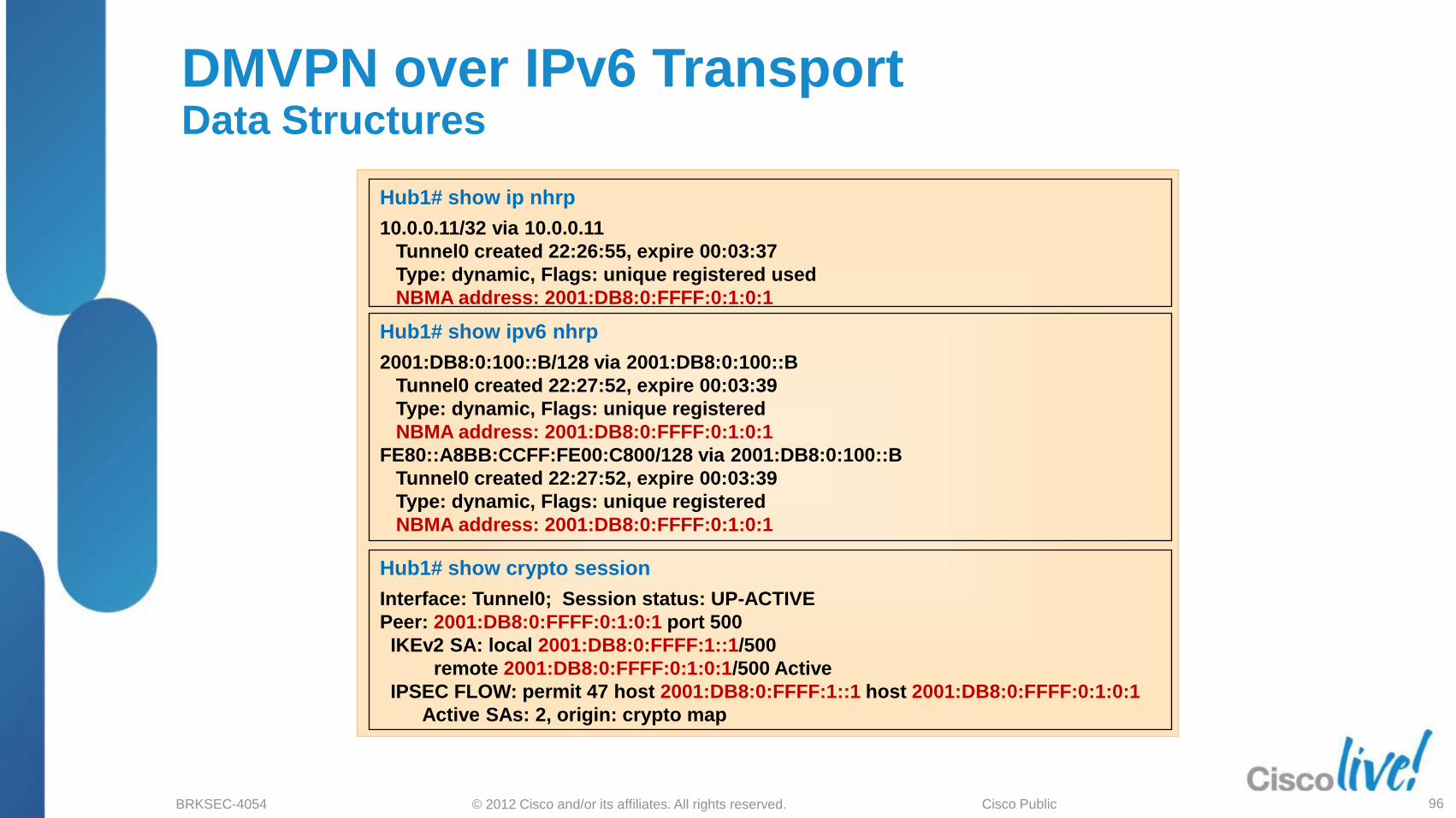
DMVPN over IPv6 TransportData Structures
Hub1# show ipv6 nhrp
2001:DB8:0:100::B/128 via 2001:DB8:0:100::B
Tunnel0 created 22:27:52, expire 00:03:39
Type: dynamic, Flags: unique registered
NBMA address: 2001:DB8:0:FFFF:0:1:0:1
FE80::A8BB:CCFF:FE00:C800/128 via 2001:DB8:0:100::B
Tunnel0 created 22:27:52, expire 00:03:39
Type: dynamic, Flags: unique registered
NBMA address: 2001:DB8:0:FFFF:0:1:0:1
Hub1# show ip nhrp
10.0.0.11/32 via 10.0.0.11
Tunnel0 created 22:26:55, expire 00:03:37
Type: dynamic, Flags: unique registered used
NBMA address: 2001:DB8:0:FFFF:0:1:0:1
Hub1# show crypto session
Interface: Tunnel0; Session status: UP-ACTIVE
Peer: 2001:DB8:0:FFFF:0:1:0:1 port 500
IKEv2 SA: local 2001:DB8:0:FFFF:1::1/500
remote 2001:DB8:0:FFFF:0:1:0:1/500 Active
IPSEC FLOW: permit 47 host 2001:DB8:0:FFFF:1::1 host 2001:DB8:0:FFFF:0:1:0:1
Active SAs: 2, origin: crypto map

© 2012 Cisco and/or its affiliates. All rights reserved.BRKSEC-4054 Cisco Public 97
Routing Protocol Features
iBGP Local-AS (15.2(2)T, 15.1(3)S (CSCtj48063))
‒ Run iBGP over DMVPNTunnel end-point routers may have different native BGP ASs
Allows „neighbor ... local-as #‟ and „neighbor ... remote-as #‟ to be the same (iBGP)
‟neighbor ... local-as #‟ is different from local native BGP AS, „router bgp #‟Almost like eBGP within the router between the native AS and the AS over DMVPN
Also use BGP Dynamic Neighbors to reduce configuration on hub
EIGRP Equal Cost MultiPath (15.2(3)T, 15.2(1)S (CSCsj31328))
‒ Destination network is reachable via more than one DMVPN (mGRE tunnel) and the ip next-hop needs to be preserved (Phase 2).„no ip next-hop-self eigrp <as> [no-ecmp-mode]‟

DMVPN Futures

© 2012 Cisco and/or its affiliates. All rights reserved.BRKSEC-4054 Cisco Public 99
DMVPN Futures
ASR
‒ Per-tunnel QoS on ASR (3.6)
‒ Dual Stack (IPv4 & IPv6) over DMVPN IPv4 (3.7)
‒ Dual Stack (IPv4 & IPv6) over DMVPN IPv6 (3.8)
Possible Future
‒ Native multicast over DMVPN
‒ Per-tunnel QoS IPv6 over DMVPN on Hub

© 2012 Cisco and/or its affiliates. All rights reserved.BRKSEC-4054 Cisco Public 100
Complete Your Online Session Evaluation Give us your feedback and you
could win fabulous prizes.Winners announced daily.
Receive 20 Passport points for each session evaluation you complete.
Complete your session evaluation online now (open a browser through our wireless network to access our portal) or visit one of the Internet stations throughout the Convention Center.
Don‟t forget to activate your Cisco Live Virtual
account for access to all session material,
communities, and on-demand and live
activities throughout the year.
Activate your account at the Cisco booth in the
World of Solutions or visit www.ciscolive.com.

© 2012 Cisco and/or its affiliates. All rights reserved.BRKSEC-4054 Cisco Public 101
Final Thoughts
Get hands-on experience with the Walk-in Labs located in World of Solutions, booth 1042
Come see demos of many key solutions and products in the main Cisco booth 2924
Visit www.ciscoLive365.com after the event for updated PDFs, on-demand session videos, networking, and more!
Follow Cisco Live! using social media:
‒ Facebook: https://www.facebook.com/ciscoliveus
‒ Twitter: https://twitter.com/#!/CiscoLive
‒ LinkedIn Group: http://linkd.in/CiscoLI