Dynamic Models Package "Standard-1" - Siemens · PDF fileDynamic Models Package...
82
Dynamic Models Package „Standard-1“ GMB Dynamic Models for PSS® Software Product Suite Revision 1.7 / October 2012
Transcript of Dynamic Models Package "Standard-1" - Siemens · PDF fileDynamic Models Package...
Dynamic Models Package „Standard-1“
GMB Dynamic Models for PSS® Software Product Suite
Revision 1.7 / October 2012
Revision 1.7 / October 2012 Page 2 of 82
Table of Contents
Revision History ........................................................................................................................... 4
1 Introduction ....................................................................................................................... 5
2 License Group “Standard-1”............................................................................................... 6
2.1 Exciters (AVR) ............................................................................................................ 6 2.1.1 AC7B_gmb - IEEE 421.5 2005 AC7B excitation system .................................... 6 2.1.2 AC8B_gmb - IEEE 421.5 2005 AC8B excitation system .................................... 8 2.1.3 BBSEX1_gmb - Brown-Boveri static excitation system model......................... 10 2.1.4 BUDCZT_gmb - Czech proportional/integral excitation system model ............ 11 2.1.5 DC3A_gmb - IEEE 421.5 2005 DC3A excitation system ................................. 12 2.1.6 EMAC1T_gmb - AEP Rockport excitation system model ................................. 13 2.1.7 ESAC1A_gmb - 1992 IEEE type AC1A excitation system model...................... 15 2.1.8 ESAC2A_gmb - 1992 IEEE type AC2A excitation system model...................... 16 2.1.9 ESAC4A_gmb - 1992 IEEE type AC4A excitation system model...................... 18 2.1.10 ESAC5A_gmb - 1992 IEEE type AC5A excitation system model...................... 19 2.1.11 ESAC6A_gmb - 1992 IEEE type AC6A excitation system model...................... 20 2.1.12 ESDC1A_gmb - 1992 IEEE type DC1A excitation system model...................... 21 2.1.13 ESDC2A_gmb - 1992 IEEE type DC2A excitation system model...................... 22 2.1.14 ESST1A_gmb - 1992 IEEE type ST1A excitation system model ....................... 23 2.1.15 ESST2A_gmb - 1992 IEEE type ST2A excitation system model ....................... 24 2.1.16 ESST3A_gmb - 1992 IEEE type ST2A excitation system model ....................... 25 2.1.17 ESST4B_gmb - IEEE type ST4B potential or compounded source-controlled
rectifier exciter ............................................................................................ 27 2.1.18 EXAC1_gmb - 1981 IEEE type AC1 excitation system model.......................... 28 2.1.19 EXAC1A_gmb - Modified type AC1 excitation system model ......................... 29 2.1.20 EXAC2_gmb - 1981 IEEE type AC2 excitation system model.......................... 30 2.1.21 EXAC4_gmb - 1981 IEEE type AC4 excitation system model.......................... 32 2.1.22 EXBAS_gmb - Basler static voltage regulator feeding dc or ac rotating exciter
model ......................................................................................................... 33 2.1.23 EXDC2_gmb - 1981 IEEE type DC2 excitation system model.......................... 35 2.1.24 EXELI_gmb - Static PI transformer fed excitation system model..................... 36 2.1.25 EXNEBB_gmb - Bus or solid fed SCR bridge excitation system model
type NEBB (NVE).......................................................................................... 37 2.1.26 EXNI _gmb - Bus or solid fed SCR bridge excitation system model
type NI (NVE)............................................................................................... 38 2.1.27 EXST1_gmb - 1981 IEEE type ST1 excitation system model ........................... 39 2.1.28 EXST2_gmb - 1981 IEEE type ST2 excitation system model ........................... 40 2.1.29 EXST2A_gmb - Modified 1981 IEEE type ST2 excitation system model .......... 41 2.1.30 EXST3_gmb - 1981 IEEE type ST3 excitation system model ........................... 42 2.1.31 IEEET2_gmb - 1968 IEEE type 2 excitation system model .............................. 43 2.1.32 IEEET3_gmb - 1968 IEEE type 3 excitation system model .............................. 44 2.1.33 IEEET4_gmb - 1968 IEEE type 4 excitation system model .............................. 45 2.1.34 IEEET5_gmb - Modified 1968 IEEE type 4 excitation system model................ 46 2.1.35 IEEEX1_gmb - 1979 IEEE type 1 excitation system model
and 1981 IEEE type DC1 model .................................................................... 47 2.1.36 IEEEX2_gmb - 1979 IEEE type 2 excitation system model.............................. 48 2.1.37 IEEEX3_gmb - 1979 IEEE type 3 excitation system model.............................. 49 2.1.38 IEEEX4_gmb - 1979 IEEE type 4 excitation system, 1981 IEEE type DC3
and 1992 IEEE type DC3A models ............................................................... 50 2.1.39 IEET1A_gmb - Modified 1968 IEEE type 1 excitation system model ............... 51 2.1.40 IEET1B_gmb - Modified 1968 IEEE type 1 excitation system model ............... 52 2.1.41 IEET5A_gmb - Modified 1968 IEEE type 4 excitation system model ............... 53 2.1.42 IEEX2A_gmb - 1979 IEEE type 2A excitation system model ........................... 54 2.1.43 IVOEX_gmb - IVO excitation system model ................................................... 55

Revision 1.7 / October 2012 Page 3 of 82
2.1.44 OEX3T_gmb - Ontario Hydro IEEE Type ST1 excitation system with semicontinuous and acting terminal voltage limiter.............................. 56
2.1.45 REXSYS_gmb - General purpose rotating excitation system model ................ 57 2.1.46 ST5B_gmb - IEEE 421.5 2005 ST5B excitation system ................................... 59 2.1.47 ST6B_gmb - IEEE 421.5 2005 ST6B excitation system ................................... 61 2.1.48 ST7B_gmb - IEEE 421.5 2005 ST7B excitation system ................................... 63 2.1.49 URST5T_gmb - IEEE proposed type ST5B excitation system ........................... 65
2.2 Governors (GOV) ..................................................................................................... 66
2.2.1 BBGOV1_gmb - Brown-Boveri turbine-governor model ................................. 66 2.2.2 CRCMGV_gmb - Cross compound turbine-governor model............................ 67 2.2.3 DEGOV_gmb - Woodward diesel governor model ......................................... 68 2.2.4 DEGOV1_gmb - Woodward diesel governor model ....................................... 69 2.2.5 GAST_gmb - Gas turbine-governor model..................................................... 70 2.2.6 HYGOV2_gmb - Hydro turbine-governor model ............................................ 71 2.2.7 IEEEG1_gmb - 1981 IEEE type 1 turbine-governor model .............................. 72 2.2.8 IEEEG2_gmb - 1981 IEEE type 2 turbine-governor model .............................. 73 2.2.9 IEEEG3_gmb - 1981 IEEE type 3 turbine-governor model .............................. 74 2.2.10 IEESGO_gmb - 1973 IEEE standard turbine-governor model.......................... 75 2.2.11 IVOGO_gmb - IVO turbine-governor model................................................... 76 2.2.12 PIDGOV_gmb - Hydro turbine and governor model ....................................... 77 2.2.13 TGOV2_gmb - Steam turbine-governor model with fast valving .................... 78 2.2.14 TGOV3_gmb - Modified IEEE type 1 turbine-governor model
with fast valving .......................................................................................... 79 2.2.15 WPIDHY_gmb - Woodward P.I.D. hydro governor model ............................... 80 2.2.16 WSIEG1_gmb - WECC modified 1981 IEEE type 1 turbine-governor model..... 81

Revision 1.7 / October 2012 Page 4 of 82
Revision History
Date Revision Author Description
2008-01-30 1.1 Ruhle Initial revision
2008-05-01 1.2 Beissler Test procedure updated + table of contents added
2010-12-22 1.3 Medak Update
2011-05-16 1.4 Medak Update
2011-09-02 Lynn Graphics update
2011-09 1.5 Medak / Angelov
New controller added and minor fixes
2011-12-20 Lin Graphics update and new controller added
2012-04-08 1.6 Lin Controller modified and Graphics update
2012-10-22 1.7 Angelov Release October 2012

Revision 1.7 / October 2012 Page 5 of 82
1 Introduction Documentation of the available “User-drawn” BOSL controllers for the PSS® Product Suite, namely: PSS®E PSS®SINCAL PSS®NETOMAC The dynamic models described here are built with the Graphical Model Builder (GMB) and consist of: Graphical model representation *_gmb.vsd BOSL Macro description *_gmb.mac Controller block diagram *_gmb.jpg General Notes: Dear user. All example descriptions included in this document are created under Windows XP operation system. If a different operation system is running, for example Windows Vista or Windows 7, please copy the complete folder “…\Program Files\PTI\NetCad\Standard-1 including subfolders to a working directory, with full write and read access. During the software operation the program pre-requires a write and read access to these folders; if this permission is not given a run time error may occur.
Revision 1.7 / October 2012 Page 6 of 82
2 License Group “Standard-1”
2.1 Exciters (AVR)
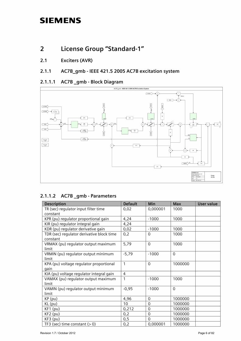
2.1.1 AC7B_gmb - IEEE 421.5 2005 AC7B excitation system
2.1.1.1 AC7B _gmb - Block Diagram
2.1.1.2 AC7B _gmb - Parameters
Description Default Min Max User value TR (sec) regulator input filter time constant
0,02 0,000001 1000
KPR (pu) regulator proportional gain 4,24 -1000 1000 KIR (pu) regulator integral gain 4,24 KDR (pu) regulator derivative gain 0,02 -1000 1000 TDR (sec) regulator derivative block time constant
0,2 0 1000
VRMAX (pu) regulator output maximum limit
5,79 0 1000
VRMIN (pu) regulator output minimum limit
-5,79 -1000 0
KPA (pu) voltage regulator proportional gain
1 0 1000000
KIA (pu) voltage regulator integral gain 4 VAMAX (pu) regulator output maximum limit
1 -1000 1000
VAMIN (pu) regulator output minimum limit
-0,95 -1000 0
KP (pu) 4,96 0 1000000 KL (pu) 10 0 1000000 KF1 (pu) 0,212 0 1000000 KF2 (pu) 0,2 0 1000000 KF3 (pu) 0,5 0 1000000 TF3 (sec) time constant (> 0) 0,2 0,000001 1000000

Revision 1.7 / October 2012 Page 7 of 82
KC (pu) rectifier loading factor proportional to commutating reactance
0,18 0 1000000
KD (pu) demagnetizing factor, function of AC exciter reactances
0,02 0,000001 1000000
KE (pu) exciter constant related fo self-excited field
1 0,000001 1000000
TE (pu) exciter time constant 1,1 0,000001 1000000 VFEMAX (pu) exciter field current limit (> 0)
6,9 0 1000
VEMIN (pu) -1 -0,001 1000 E1 3,02 S(E1) 0,075 E2 6,3 S(E2) 0,44
2.1.1.3 AC7B _gmb - Example dyr-record for PSS®E
For bus 38, generator-id ‘1’ the dyr-record may be: 'USRMBL', 'AC7B_gmb', 38, '1', 0.02 4.24 4.24 0.02 0.2 5.79 -5.79 1 4 1 -0.95 4.96 10 0.212 0.2 0.5 0.2 0.18 0.02 1 1.1 6.9 -1 3.02 0.075 6.3 0.44/
Revision 1.7 / October 2012 Page 8 of 82
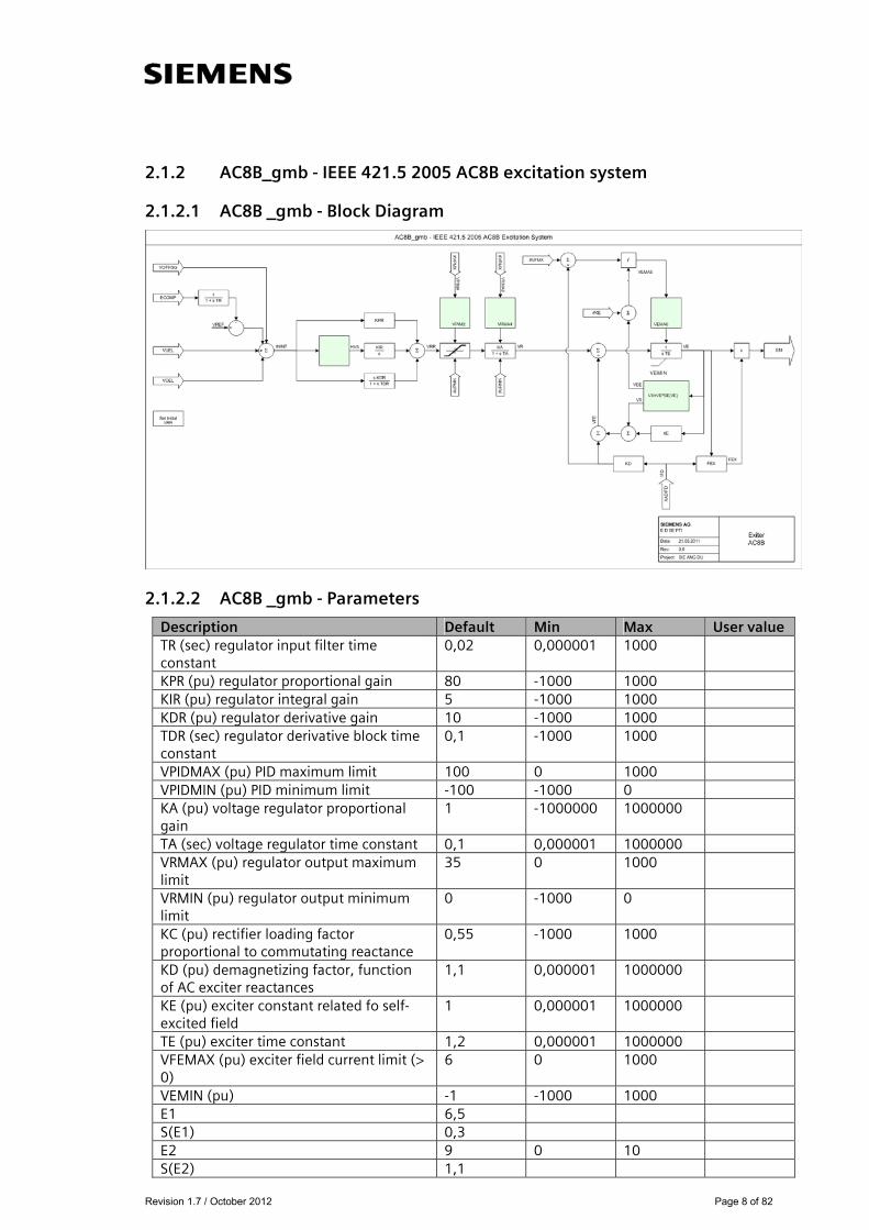
2.1.2 AC8B_gmb - IEEE 421.5 2005 AC8B excitation system
2.1.2.1 AC8B _gmb - Block Diagram
2.1.2.2 AC8B _gmb - Parameters
Description Default Min Max User value TR (sec) regulator input filter time constant
0,02 0,000001 1000
KPR (pu) regulator proportional gain 80 -1000 1000 KIR (pu) regulator integral gain 5 -1000 1000 KDR (pu) regulator derivative gain 10 -1000 1000 TDR (sec) regulator derivative block time constant
0,1 -1000 1000
VPIDMAX (pu) PID maximum limit 100 0 1000 VPIDMIN (pu) PID minimum limit -100 -1000 0 KA (pu) voltage regulator proportional gain
1 -1000000 1000000
TA (sec) voltage regulator time constant 0,1 0,000001 1000000 VRMAX (pu) regulator output maximum limit
35 0 1000
VRMIN (pu) regulator output minimum limit
0 -1000 0
KC (pu) rectifier loading factor proportional to commutating reactance
0,55 -1000 1000
KD (pu) demagnetizing factor, function of AC exciter reactances
1,1 0,000001 1000000
KE (pu) exciter constant related fo self-excited field
1 0,000001 1000000
TE (pu) exciter time constant 1,2 0,000001 1000000 VFEMAX (pu) exciter field current limit (> 0)
6 0 1000
VEMIN (pu) -1 -1000 1000 E1 6,5 S(E1) 0,3 E2 9 0 10 S(E2) 1,1

Revision 1.7 / October 2012 Page 9 of 82
2.1.2.3 AC8B _gmb - Example dyr-record for PSS®E
For bus 38, generator-id ‘1’ the dyr-record may be: 'USRMBL','AC8B_gmb', 38,'1', 0.02 80 5 10 0.1 100 -100 1 0.1 35 0 0.55 1.1 1 1.2 6 -1 6.5 0.3 9 1.1 /

Revision 1.7 / October 2012 Page 10 of 82
2.1.3 BBSEX1_gmb - Brown-Boveri static excitation system model
2.1.3.1 BBSEX1_gmb - Block Diagram
2.1.3.2 BBSEX1_gmb - Parameters
Description Default Min Max User value TF (sec) 0,025 0 0,49 K 10,01 10,01 499,99 T1 (> 0) (sec) 0,1 0,021 9,99 T2 (>0) (sec) 0,1 0,021 9,99 T3 (sec) 1 0 T4 (sec) 4 0 VRMAX 5 0,51 9,99 VRMIN -3 -9,99 -0,01 EFDMAX 4,5 EFDMIN 0 Switch 1
2.1.3.3 BBSEX1_gmb - Example dyr-record for PSS®E
For bus 38, generator-id ‘1’ the dyr-record may be: 'USRMBL', 'BBSEX1_gmb', 38, '1', 0.025 10.01 0.1 0.1 1 4 5 -3 4.5 0 1 /

Revision 1.7 / October 2012 Page 11 of 82
2.1.4 BUDCZT_gmb - Czech proportional/integral excitation system model
2.1.4.1 BUDCZT_gmb - Block Diagram
2.1.4.2 BUDCZT_gmb - Parameters
Description Default Min Max User value KP (pu) 12 KA > 0 (pu) 3,4 KE > 0 (pu) 1 TR (sec) 0,1 TI > 0 (sec) 1 TA (sec) 0,1 TE (sec) 0,2 URMAX (pu) 10 URMIN (pu) -10 EFDMAX (pu) 7,5 EFDMIN (pu) -7,5
2.1.4.3 BUDCZT_gmb - Example dyr-record for PSS®E
For bus 38, generator-id ‘1’ the dyr-record may be: 'USRMBL', 'BUDCZT_gmb', 38, '1', 12 3.4 1 0.1 1 0.1 0.2 10 -10 7.5 -7.5 /

Revision 1.7 / October 2012 Page 12 of 82
2.1.5 DC3A_gmb - IEEE 421.5 2005 DC3A excitation system
2.1.5.1 DC3A_gmb - Block Diagram
2.1.5.2 DC3A_gmb - Parameters
Description Default Min Max User value TR Regulator input time constant (sec) 0,1 KV (pu) limit on fast raise/lower contact setting 0,08
VRMAX (pu) regulator maximum limit 2,1 VRMIN (pu) regulator minimum limit 0 TRH ( > 0) Rheostat motor travel time (sec) 99 TE ( > 0) exciter time-constant (sec) 0,14 KE (pu) exciter constant related to self-excited field 0,099
VEMIN (pu) exciter minimum limit -100 E1 4 SE (E1) 0,4 E2 5 SE (E2) 0,5
2.1.5.3 DC3A_gmb - Example dyr-record for PSS®E
For bus 38, generator-id ‘1’ the dyr-record may be: 'USRMBL','DC3A_gmb', 38,'1', 0.1 0.08 2.1 0 99 0.14 0.099 -100 4 0.4 5 0.5/

Revision 1.7 / October 2012 Page 13 of 82
2.1.6 EMAC1T_gmb - AEP Rockport excitation system model
2.1.6.1 EMAC1T_gmb - Block Diagram
2.1.6.2 EMAC1T_gmb - Parameters
Description Default Min Max User value TR (sec) 0,025 T4 (sec) 0,1 T3 (sec) 0,2 KA 10 TA (sec) 0,1 VRMAX 7 VRMIN -7 TE > 0 (sec) 0,14 KF 2,7 TF > 0 (sec) 12 KC 0,1 KD 0,4 KE 1 E1 4 SE (E1) 0,4 E2 5 SE (E2) 0,5 T6 (sec) 0,2 T5 (sec) 0,2 T2 (sec) 2 T1 (sec) 0,06 KFE 2 TFE (sec) 3

Revision 1.7 / October 2012 Page 14 of 82
2.1.6.3 EMAC1T_gmb - Example dyr-record for PSS®E
For bus 38, generator-id ‘1’ the dyr-record may be: 'USRMBL', 'EMAC1T_gmb', 38, '1', 0.025 0.1 0.2 10 0.1 7 -7 0.14 2.7 12 0.1 0.4 1 4 0.4 5 0.5 0.2 0.2 2 0.06 2 3 /

Revision 1.7 / October 2012 Page 15 of 82
2.1.7 ESAC1A_gmb - 1992 IEEE type AC1A excitation system model
2.1.7.1 ESAC1A_gmb - Block Diagram
2.1.7.2 ESAC1A_gmb - Parameters
Description Default Min Max User value TR (sec) 0,01 0 0,49 TB (sec) 0,1 0 19,99 TC (sec) 0,2 0 19,99 KA 80 0,01 999,99 TA (sec) 0,2 0 9,99 VAMAX 15 0 15 VAMIN -15 -15 0 TE > 0 (sec) 0,2 0,021 1,49 KF 0,03 0 0,29 TF > 0 (sec) 1,49 0,021 1,49 KC 1 0 1 KD 0,4 0 1 KE 1 0 1 E1 4 0 SE (E1) 0,4 0 1 E2 5 0 SE (E2) 0,5 0 VRMAX 14,99 0 14,99 VRMIN -14,99 -14,99 0
2.1.7.3 ESAC1A_gmb - Example dyr-record for PSS®E
For bus 38, generator-id ‘1’ the dyr-record may be: 'USRMBL', 'ESAC1A_gmb', 38, '1', 0.01 0.1 0.2 80 0.2 15 -15 0.2 0.03 1.49 1 0.4 1 4 0.4 5 0.5 14.99 -14.99 /
Revision 1.7 / October 2012 Page 16 of 82
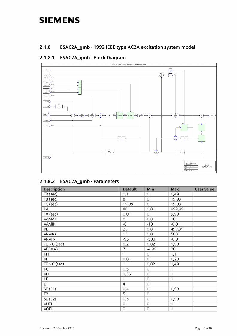
2.1.8 ESAC2A_gmb - 1992 IEEE type AC2A excitation system model
2.1.8.1 ESAC2A_gmb - Block Diagram
2.1.8.2 ESAC2A_gmb - Parameters
Description Default Min Max User value TR (sec) 0,1 0 0,49 TB (sec) 8 0 19,99 TC (sec) 19,99 0 19,99 KA 80 0,01 999,99 TA (sec) 0,01 0 9,99 VAMAX 8 0,01 10 VAMIN -8 -10 -0,01 KB 25 0,01 499,99 VRMAX 15 0,01 500 VRMIN -95 -500 -0,01 TE > 0 (sec) 0,2 0,021 1,99 VFEMAX 7 -4,99 20 KH 1 0 1,1 KF 0,01 0 0,29 TF > 0 (sec) 1 0,021 1,49 KC 0,5 0 1 KD 0,35 0 1 KE 1 0 1 E1 4 0 SE (E1) 0,4 0 0,99 E2 5 0 SE (E2) 0,5 0 0,99 VUEL 0 0 1 VOEL 0 0 1

Revision 1.7 / October 2012 Page 17 of 82
2.1.8.3 ESAC2A_gmb - Example dyr-record for PSS®E
For bus 38, generator-id ‘1’ the dyr-record may be: 'USRMBL', 'ESAC2A_gmb', 38, '1', 0.1 8 19.99 80 0.01 8 -8 25 15 -95 0.2 7 1 0.01 1 0.5 0.35 1 4 0.4 5 0.5 0 0 /
Revision 1.7 / October 2012 Page 18 of 82
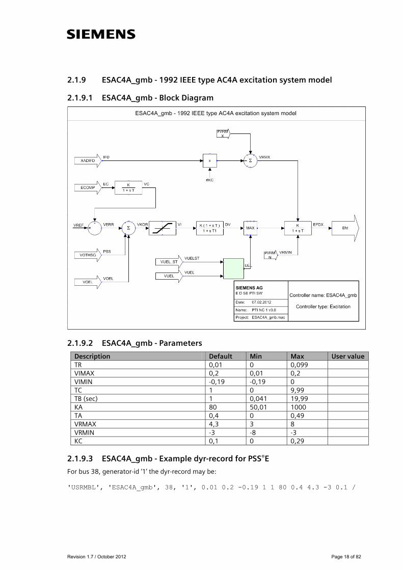
2.1.9 ESAC4A_gmb - 1992 IEEE type AC4A excitation system model
2.1.9.1 ESAC4A_gmb - Block Diagram
2.1.9.2 ESAC4A_gmb - Parameters
Description Default Min Max User value TR 0,01 0 0,099 VIMAX 0,2 0,01 0,2 VIMIN -0,19 -0,19 0 TC 1 0 9,99 TB (sec) 1 0,041 19,99 KA 80 50,01 1000 TA 0,4 0 0,49 VRMAX 4,3 3 8 VRMIN -3 -8 -3 KC 0,1 0 0,29
2.1.9.3 ESAC4A_gmb - Example dyr-record for PSS®E
For bus 38, generator-id ‘1’ the dyr-record may be: 'USRMBL', 'ESAC4A_gmb', 38, '1', 0.01 0.2 -0.19 1 1 80 0.4 4.3 -3 0.1 /
Revision 1.7 / October 2012 Page 19 of 82
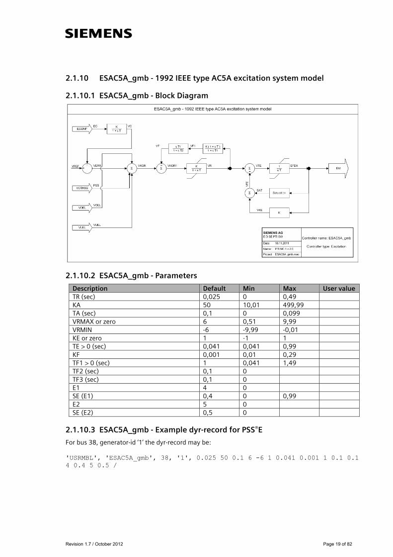
2.1.10 ESAC5A_gmb - 1992 IEEE type AC5A excitation system model
2.1.10.1 ESAC5A_gmb - Block Diagram
2.1.10.2 ESAC5A_gmb - Parameters
Description Default Min Max User value TR (sec) 0,025 0 0,49 KA 50 10,01 499,99 TA (sec) 0,1 0 0,099 VRMAX or zero 6 0,51 9,99 VRMIN -6 -9,99 -0,01 KE or zero 1 -1 1 TE > 0 (sec) 0,041 0,041 0,99 KF 0,001 0,01 0,29 TF1 > 0 (sec) 1 0,041 1,49 TF2 (sec) 0,1 0 TF3 (sec) 0,1 0 E1 4 0 SE (E1) 0,4 0 0,99 E2 5 0 SE (E2) 0,5 0
2.1.10.3 ESAC5A_gmb - Example dyr-record for PSS®E
For bus 38, generator-id ‘1’ the dyr-record may be: 'USRMBL', 'ESAC5A_gmb', 38, '1', 0.025 50 0.1 6 -6 1 0.041 0.001 1 0.1 0.1 4 0.4 5 0.5 /

Revision 1.7 / October 2012 Page 20 of 82
2.1.11 ESAC6A_gmb - 1992 IEEE type AC6A excitation system model
2.1.11.1 ESAC6A_gmb - Block Diagram
2.1.11.2 ESAC6A_gmb - Parameters
Description Default Min Max User value TR (sec) 0,025 0 0,49 KA 50 0,01 999,99 TA (sec) 0,1 0 9,99 TK (sec) 1 0,01 9,99 TB (sec) 0,1 0 19,99 TC (sec) 0,2 0 19,99 VAMAX 10 0,01 10 VAMIN -10 -10 -0,01 VRMAX 20 0,01 100 VRMIN -20 -100 -0,01 TE (>0) (sec) 1 0,021 1,99 VFELIM 0,4 0,01 20 KH 0 0 1,1 VHMAX 7 0,01 100 TH (sec) 0,02 0 1 TJ (sec) 1 0 1 KC 0,35 0 1 KD 1 0,01 2 KE 0,034 0,01 2 E1 4 0 SE (E1) 0,4 0 1 E2 5 0 SE (E2) 0,5 0
2.1.11.3 ESAC6A_gmb - Example dyr-record for PSS®E
For bus 38, generator-id ‘1’ the dyr-record may be: 'USRMBL', 'ESAC6A_gmb', 38, '1', 0.025 50 0.1 1 0.1 0.2 10 -10 20 -20 1 0.4 0 7 0.02 1 0.35 1 0.034 4 0.4 5 0.5 /

Revision 1.7 / October 2012 Page 21 of 82
2.1.12 ESDC1A_gmb - 1992 IEEE type DC1A excitation system model
2.1.12.1 ESDC1A_gmb - Block Diagram
2.1.12.2 ESDC1A_gmb - Parameters
Description Default Min Max User value TR (sec) 0,1 0 0,49 KA 50 10,01 499,99 TA (sec) 0,1 0 0,99 TB (sec) 0,1 0 TC (sec) 0,2 0 VRMAX or zero 9,99 0,51 9,99 VRMIN -9,99 -9,99 -0,01 KE or zero 1 -1 1 TE (> 0) (sec) 0,2 0,041 0,99 KF 0,11 0,01 0,29 TF1 (> 0) (sec) 1 0,041 1,49 Switch 1 0 1 E1 2,47 0 SE (E1) 0,035 0 0,99 E2 3,5 0 SE (E2) 0,5 0
2.1.12.3 ESDC1A_gmb - Example dyr-record for PSS®E
For bus 38, generator-id ‘1’ the dyr-record may be: 'USRMBL', 'ESDC1A_gmb', 38, '1', 0.1 50 0.1 0.1 0.2 9.99 -9.99 1 0.2 0.11 1 1 2.47 0.035 3.5 0.5 /

Revision 1.7 / October 2012 Page 22 of 82
2.1.13 ESDC2A_gmb - 1992 IEEE type DC2A excitation system model
2.1.13.1 ESDC2A_gmb - Block Diagram
2.1.13.2 ESDC2A_gmb - Parameters
Description Default Min Max User value TR (sec) 0,1 0 0,49 KA 10,01 10,01 499,99 TA (sec) 0,06 0 0,99 TB (sec) 0,1 0 TC (sec) 0,2 0 VRMAX or zero 9,99 0,51 9,99 VRMIN -9,99 -9,99 -0,01 KE or zero 1 -1 1 TE (> 0) (sec) 0,08 0,041 1,99 KF 0,11 0,01 0,29 TF1 (> 0) (sec) 1 0,041 1,49 Switch 1 0 1 E1 2,47 0 SE (E1) 0,035 0 0,99 E2 3,5 0 SE (E2) 0,5 0
2.1.13.3 ESDC2A_gmb - Example dyr-record for PSS®E
For bus 38, generator-id ‘1’ the dyr-record may be: 'USRMBL', 'ESDC2A_gmb', 38, '1', 0.1 10.01 0.06 0.1 0.2 9.99 -9.99 1 0.08 0.11 1 1 2.47 0.035 3.5 0.5 /

Revision 1.7 / October 2012 Page 23 of 82
2.1.14 ESST1A_gmb - 1992 IEEE type ST1A excitation system model
2.1.14.1 ESST1A_gmb - Block Diagram
2.1.14.2 ESST1A_gmb - Parameters
Description Default Min Max User value UEL 1 VOS 1 TR (sec) 0,1 0 0,1 VIMAX 0,2 0 0,2 VIMIN -0,2 -0,3 0 TC (sec) 0,01 0 10 TB (sec) 10 0,04 20 TC1 (sec) 0,01 0 10 TB1 (sec) 0,1 0,04 20 KA 51 50 1000 TA (sec) 0,01 0 0,5 VAMAX 4,6 3 8 VAMIN -4,6 -8 -3 VRMAX 3,4 3 8 VRMIN -3,4 -8 -3 KC 0,01 0 0,3 KF 0,1 0 0,3 TF > 0 (sec) 0,31 0,3 1,5 KLR 1 0 5 ILR 2 0 5
2.1.14.3 ESST1A_gmb - Example dyr-record for PSS®E
For bus 38, generator-id ‘1’ the dyr-record may be: 'USRMBL', 'ESST1A_gmb', 38, '1', 1 1 0.1 0.2 -0.2 0.01 10 0.01 0.1 51 0.01 4.6 -4.6 3.4 -3.4 0.01 0.1 0.31 1 2 /
Revision 1.7 / October 2012 Page 24 of 82
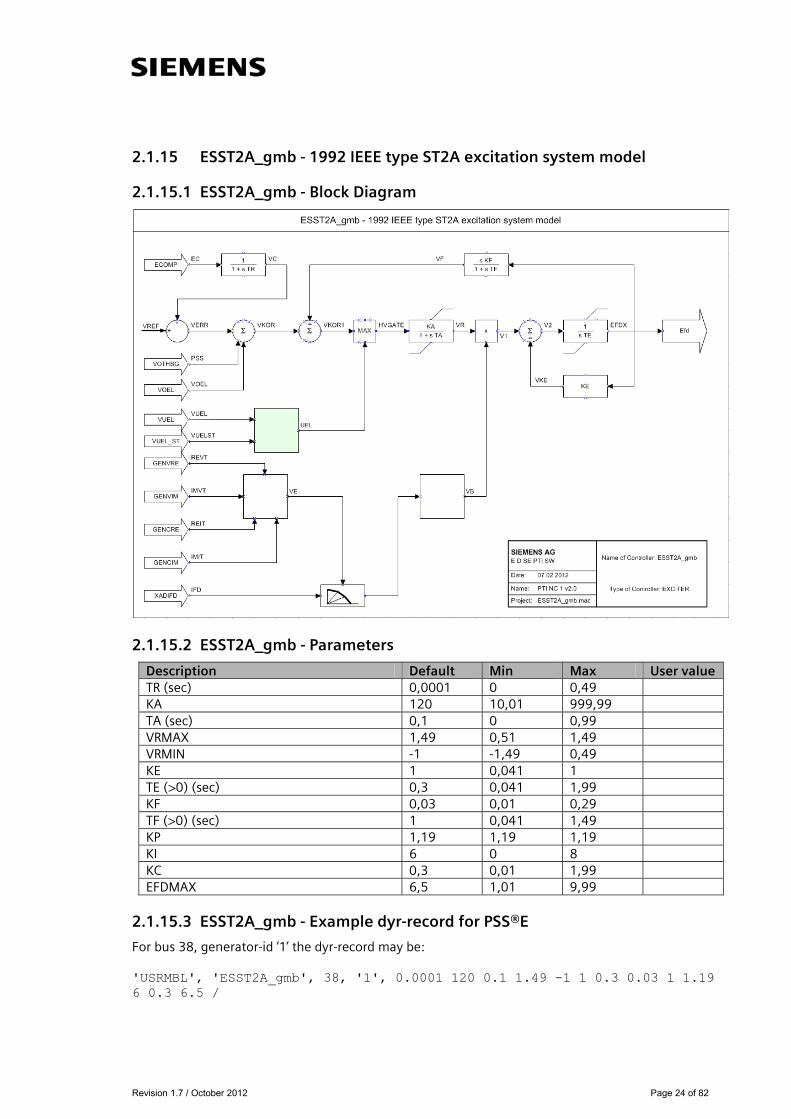
2.1.15 ESST2A_gmb - 1992 IEEE type ST2A excitation system model
2.1.15.1 ESST2A_gmb - Block Diagram
2.1.15.2 ESST2A_gmb - Parameters
Description Default Min Max User value TR (sec) 0,0001 0 0,49
KA 120 10,01 999,99
TA (sec) 0,1 0 0,99
VRMAX 1,49 0,51 1,49
VRMIN -1 -1,49 0,49
KE 1 0,041 1
TE (>0) (sec) 0,3 0,041 1,99
KF 0,03 0,01 0,29
TF (>0) (sec) 1 0,041 1,49
KP 1,19 1,19 1,19
KI 6 0 8
KC 0,3 0,01 1,99
EFDMAX 6,5 1,01 9,99
2.1.15.3 ESST2A_gmb - Example dyr-record for PSS®E
For bus 38, generator-id ‘1’ the dyr-record may be: 'USRMBL', 'ESST2A_gmb', 38, '1', 0.0001 120 0.1 1.49 -1 1 0.3 0.03 1 1.19 6 0.3 6.5 /
Revision 1.7 / October 2012 Page 25 of 82
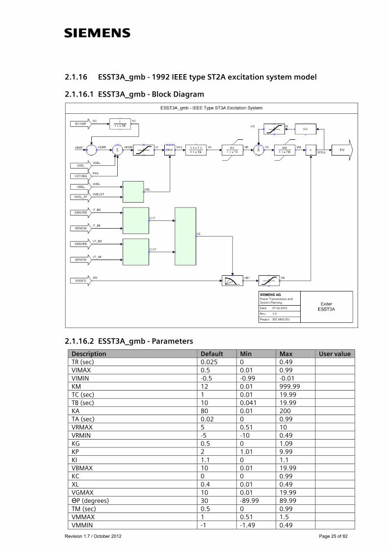
2.1.16 ESST3A_gmb - 1992 IEEE type ST2A excitation system model
2.1.16.1 ESST3A_gmb - Block Diagram
2.1.16.2 ESST3A_gmb - Parameters
Description Default Min Max User value TR (sec) 0.025 0 0.49 VIMAX 0.5 0.01 0.99 VIMIN -0.5 -0.99 -0.01 KM 12 0.01 999.99 TC (sec) 1 0.01 19.99 TB (sec) 10 0.041 19.99 KA 80 0.01 200 TA (sec) 0.02 0 0.99 VRMAX 5 0.51 10 VRMIN -5 -10 0.49 KG 0.5 0 1.09 KP 2 1.01 9.99 KI 1.1 0 1.1 VBMAX 10 0.01 19.99 KC 0 0 0.99 XL 0.4 0.01 0.49 VGMAX 10 0.01 19.99 ӨP (degrees) 30 -89.99 89.99 TM (sec) 0.5 0 0.99 VMMAX 1 0.51 1.5 VMMIN -1 -1.49 0.49

Revision 1.7 / October 2012 Page 26 of 82
2.1.16.3 ESST3A_gmb - Example dyr-record for PSS®E
For bus 38, generator-id ‘1’ the dyr-record may be: 'USRMBL', 'ESST3A_gmb', 38, '1', 0.025 0.5 -0.5 12 1 10 80 0.02 5 -5 0.5 2 1.1 10 0 0.4 10 30 0.5 1 -1/

Revision 1.7 / October 2012 Page 27 of 82
2.1.17 ESST4B_gmb - IEEE type ST4B potential or compounded source-controlled rectifier exciter
2.1.17.1 ESST4B_gmb - Block Diagram
2.1.17.2 ESST4B_gmb - Parameters
Description Default Min Max User value TR (sec) 0.3 0 0.49 KPR 2.97 0 75 KIR 2.97 0 75 VRMAX 1 0.8 10 VRMIN -0.87 -6 0 TA (sec) 0.01 0 0.99 KPM 1 0 1.2 KIM 0.2 0 18 VMMAX 1 0.8 118 VMMIN -0.87 -118.8 0 KG 0.1 0 1.09 KP 6.73 1 9.99 KI 0.1 01.1 VBMAX 8.41 1.01 19.99 KC 0.1 0 0.99 XL 0 0 0.49 THETAP 0 -89.99 89.99
2.1.17.3 ESST4B_gmb - Example dyr-record for PSS®E
For bus 38, generator-id ‘1’ the dyr-record may be: 'USRMBL','ESST4B_gmb', 38,'1', 0.3 2.97 2.97 1 -0.87 0.01 1 0.2 1 -0.87 0.1 6.73 0.1 8.41 0.1 0 0 /
Revision 1.7 / October 2012 Page 28 of 82
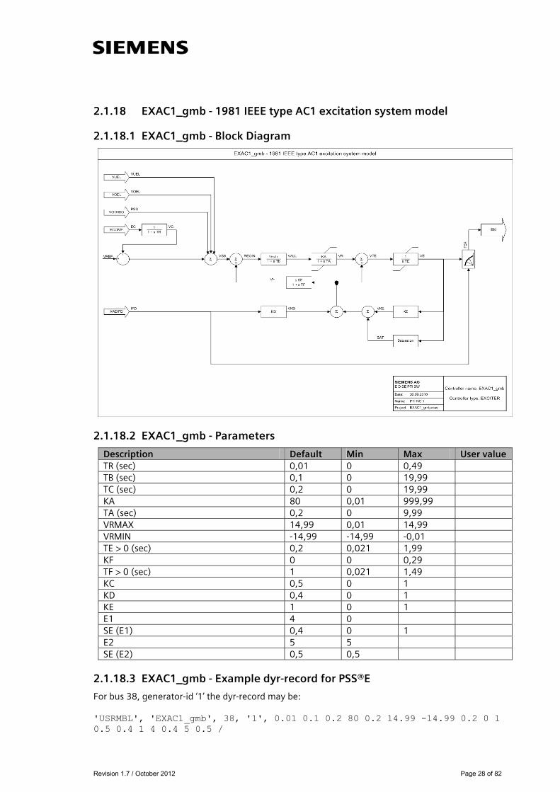
2.1.18 EXAC1_gmb - 1981 IEEE type AC1 excitation system model
2.1.18.1 EXAC1_gmb - Block Diagram
2.1.18.2 EXAC1_gmb - Parameters
Description Default Min Max User value TR (sec) 0,01 0 0,49
TB (sec) 0,1 0 19,99
TC (sec) 0,2 0 19,99
KA 80 0,01 999,99
TA (sec) 0,2 0 9,99
VRMAX 14,99 0,01 14,99
VRMIN -14,99 -14,99 -0,01
TE > 0 (sec) 0,2 0,021 1,99
KF 0 0 0,29
TF > 0 (sec) 1 0,021 1,49
KC 0,5 0 1
KD 0,4 0 1
KE 1 0 1
E1 4 0
SE (E1) 0,4 0 1
E2 5 5
SE (E2) 0,5 0,5
2.1.18.3 EXAC1_gmb - Example dyr-record for PSS®E
For bus 38, generator-id ‘1’ the dyr-record may be: 'USRMBL', 'EXAC1_gmb', 38, '1', 0.01 0.1 0.2 80 0.2 14.99 -14.99 0.2 0 1 0.5 0.4 1 4 0.4 5 0.5 /

Revision 1.7 / October 2012 Page 29 of 82
2.1.19 EXAC1A_gmb - Modified type AC1 excitation system model
2.1.19.1 EXAC1A_gmb - Block Diagram
2.1.19.2 EXAC1A_gmb - Parameters
Description Default Min Max User value TR (sec) 0,1 0 0,49 TB (sec) 0,1 0 19,99 TC (sec) 0,2 0 19,99 KA 80 0,01 999,99 TA (sec) 0,2 0 9,99 VRMAX 10 0,01 10 VRMIN -10 -10 -0,01 TE > 0 (sec) 0,2 0,021 1,99 KF 0,03 0 0,29 TF > 0 (sec) 1 0,021 1,49 KC 0,5 0 1 KD 0,4 0 1 KE 1 0,01 1 E1 4 0 SE (E1) 0,4 0 1 E2 5 0 SE (E2) 0,5 0
2.1.19.3 EXAC1A_gmb - Example dyr-record for PSS®E
For bus 38, generator-id ‘1’ the dyr-record may be: 'USRMBL', 'EXAC1A_gmb', 38, '1', 0.1 0.1 0.2 80 0.2 10 -10 0.2 0.03 1 0.5 0.4 1 4 0.4 5 0.5 /
Revision 1.7 / October 2012 Page 30 of 82
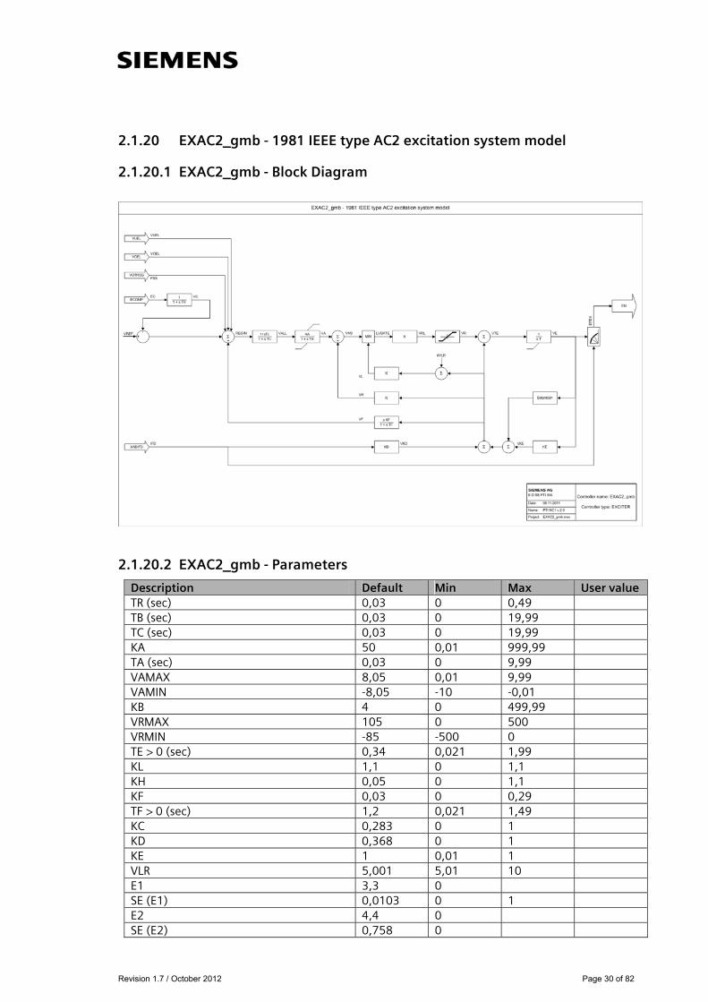
2.1.20 EXAC2_gmb - 1981 IEEE type AC2 excitation system model
2.1.20.1 EXAC2_gmb - Block Diagram
2.1.20.2 EXAC2_gmb - Parameters
Description Default Min Max User value TR (sec) 0,03 0 0,49 TB (sec) 0,03 0 19,99 TC (sec) 0,03 0 19,99 KA 50 0,01 999,99 TA (sec) 0,03 0 9,99 VAMAX 8,05 0,01 9,99 VAMIN -8,05 -10 -0,01 KB 4 0 499,99 VRMAX 105 0 500 VRMIN -85 -500 0 TE > 0 (sec) 0,34 0,021 1,99 KL 1,1 0 1,1 KH 0,05 0 1,1 KF 0,03 0 0,29 TF > 0 (sec) 1,2 0,021 1,49 KC 0,283 0 1 KD 0,368 0 1 KE 1 0,01 1 VLR 5,001 5,01 10 E1 3,3 0 SE (E1) 0,0103 0 1 E2 4,4 0 SE (E2) 0,758 0

Revision 1.7 / October 2012 Page 31 of 82
2.1.20.3 EXAC2_gmb - Example dyr-record for PSS®E
For bus 38, generator-id ‘1’ the dyr-record may be: 'USRMBL', 'EXAC2A_gmb', 38, '1', 0.03 0.03 0.03 50 0.03 8.05 -8.05 4 105 -85 0.34 1.1 0.05 0.03 1.2 0.283 0.368 1 5.001 3.3 0.0103 4.4 0.0758 /

Revision 1.7 / October 2012 Page 32 of 82
2.1.21 EXAC4_gmb - 1981 IEEE type AC4 excitation system model
2.1.21.1 EXAC4_gmb - Block Diagram
2.1.21.2 EXAC4_gmb - Parameters
Description Default Min Max User value TR (sec) 0,09 0 0,09
VIMAX 0,2 0,01 0,2
VIMIN -0,19 -0,19 0
TC 0,1 0 9,99
TB (sec) 0,2 0,041 19,99
KA 50,01 50,01 1000
TA 0,1 0 0,49
VRMAX 4,91 3 8
VRMIN -4,91 -8 -3
KC 0,1 0 0,29
2.1.21.3 EXAC4_gmb - Example dyr-record for PSS®E
For bus 38, generator-id ‘1’ the dyr-record may be: 'USRMBL', 'EXAC4_gmb', 38, '1', 0.09 0.2 -0.19 0.1 0.2 50.01 0.1 4.91 -4.91 0.1 /
Revision 1.7 / October 2012 Page 33 of 82
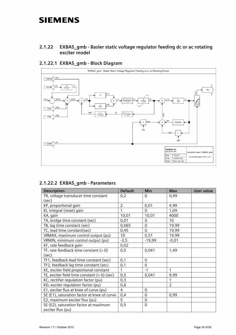
2.1.22 EXBAS_gmb - Basler static voltage regulator feeding dc or ac rotating exciter model
2.1.22.1 EXBAS_gmb - Block Diagram
2.1.22.2 EXBAS_gmb - Parameters
Description Default Min Max User value TR, voltage transducer time constant (sec)
0,2 0 0,49
KP, proportional gain 2 0,01 4,99
KI, integral (reset) gain 1 0 1,09
KA, gain 10,01 10,01 4000
TA, bridge time constant (sec) 0,01 0 10
TB, lag time constant (sec) 0,065 0 19,99
TC, lead time constant(sec) 0,45 0 19,99
VRMAX, maximum control output (pu) 10 0,51 19,99
VRMIN, minimum control output (pu) -3,5 -19,99 -0,01
KF, rate feedback gain 0,02
TF, rate feedback time constant (> 0) (sec)
0,5 0,041 1,49
TF1, feedback lead time constant (sec) 0,1 0
TF2, feedback lag time constant (sec) 0,1 0
KE, exciter field proportional constant 1 -1 1
TE, exciter field time constant (> 0) (sec) 0,5 0,041 9,99
KC, rectifier regulation factor (pu) 0,3 1
KD, exciter regulation factor (pu) 0,6 2
E1, exciter flux at knee of curve (pu) 4 0
SE (E1), saturation factor at knee of curve 0,4 0 0,99
E2, maximum exciter flux (pu) 5 0
SE (E2), saturation factor at maximum exciter flux (pu)
0,5 0
Revision 1.7 / October 2012 Page 34 of 82
2.1.22.3 EXBAS_gmb - Example dyr-record for PSS®E
For bus 38, generator-id ‘1’ the dyr-record may be: 'USRMBL', 'EXBAS_gmb', 38, '1', 0.2 2 1 10.01 0.01 0.065 0.45 10 -3.5 0.02 0.5 0.1 0.1 1 0.5 0.3 0.6 4 0.4 5 0.5 /
Revision 1.7 / October 2012 Page 35 of 82
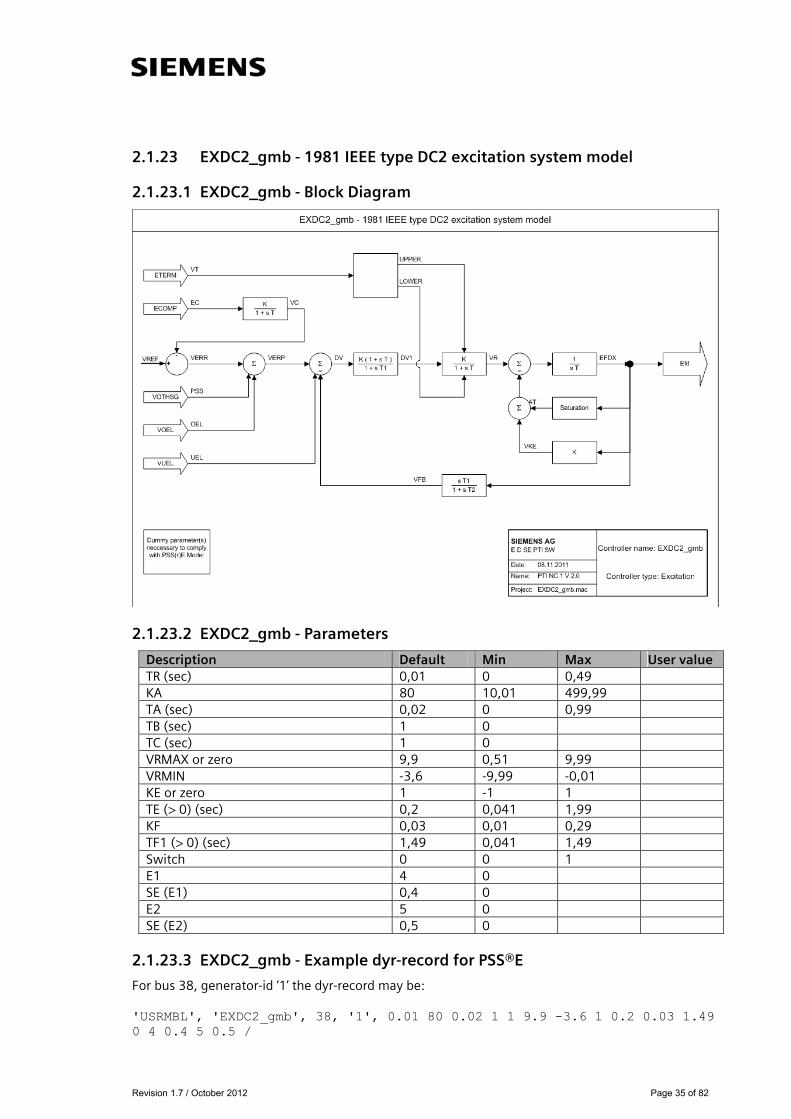
2.1.23 EXDC2_gmb - 1981 IEEE type DC2 excitation system model
2.1.23.1 EXDC2_gmb - Block Diagram
2.1.23.2 EXDC2_gmb - Parameters
Description Default Min Max User value TR (sec) 0,01 0 0,49 KA 80 10,01 499,99 TA (sec) 0,02 0 0,99 TB (sec) 1 0 TC (sec) 1 0 VRMAX or zero 9,9 0,51 9,99 VRMIN -3,6 -9,99 -0,01 KE or zero 1 -1 1 TE (> 0) (sec) 0,2 0,041 1,99 KF 0,03 0,01 0,29 TF1 (> 0) (sec) 1,49 0,041 1,49 Switch 0 0 1 E1 4 0 SE (E1) 0,4 0 E2 5 0 SE (E2) 0,5 0
2.1.23.3 EXDC2_gmb - Example dyr-record for PSS®E
For bus 38, generator-id ‘1’ the dyr-record may be: 'USRMBL', 'EXDC2_gmb', 38, '1', 0.01 80 0.02 1 1 9.9 -3.6 1 0.2 0.03 1.49 0 4 0.4 5 0.5 /
Revision 1.7 / October 2012 Page 36 of 82
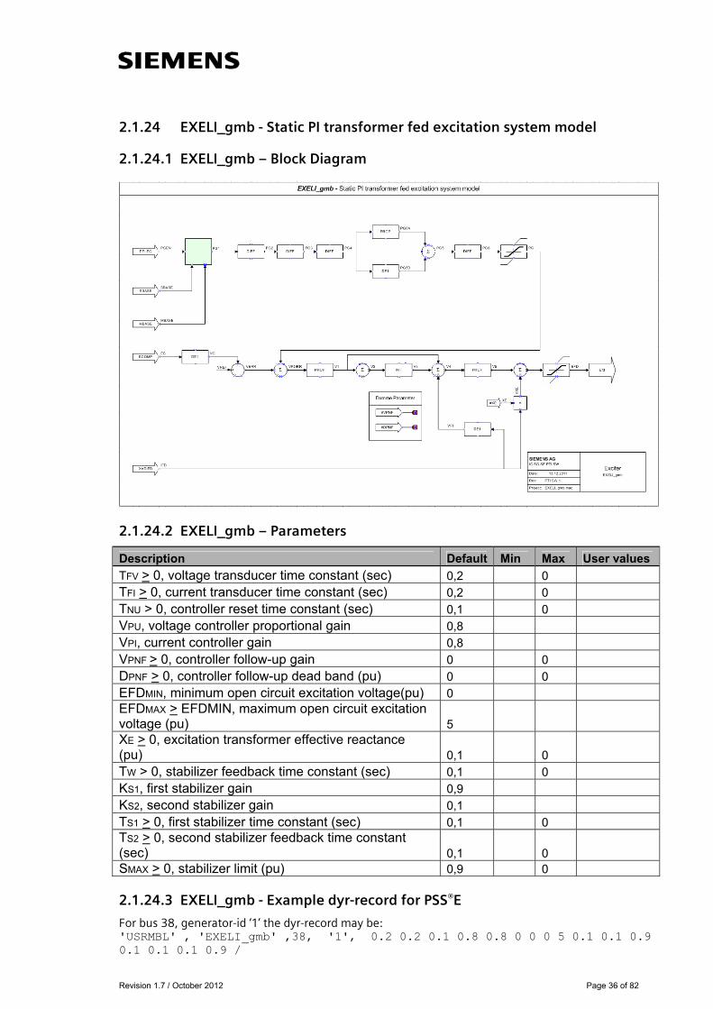
2.1.24 EXELI_gmb - Static PI transformer fed excitation system model
2.1.24.1 EXELI_gmb – Block Diagram
2.1.24.2 EXELI_gmb – Parameters
Description Default Min Max User values
TFV > 0, voltage transducer time constant (sec) 0,2 0 TFI > 0, current transducer time constant (sec) 0,2 0 TNU > 0, controller reset time constant (sec) 0,1 0 VPU, voltage controller proportional gain 0,8 VPI, current controller gain 0,8 VPNF > 0, controller follow-up gain 0 0 DPNF > 0, controller follow-up dead band (pu) 0 0 EFDMIN, minimum open circuit excitation voltage(pu) 0 EFDMAX > EFDMIN, maximum open circuit excitation voltage (pu) 5 XE > 0, excitation transformer effective reactance (pu) 0,1 0 TW > 0, stabilizer feedback time constant (sec) 0,1 0 KS1, first stabilizer gain 0,9 KS2, second stabilizer gain 0,1 TS1 > 0, first stabilizer time constant (sec) 0,1 0 TS2 > 0, second stabilizer feedback time constant (sec) 0,1 0 SMAX > 0, stabilizer limit (pu) 0,9 0
2.1.24.3 EXELI_gmb - Example dyr-record for PSS®E
For bus 38, generator-id ‘1’ the dyr-record may be: 'USRMBL' , 'EXELI_gmb' ,38, '1', 0.2 0.2 0.1 0.8 0.8 0 0 0 5 0.1 0.1 0.9 0.1 0.1 0.1 0.9 /
Revision 1.7 / October 2012 Page 37 of 82
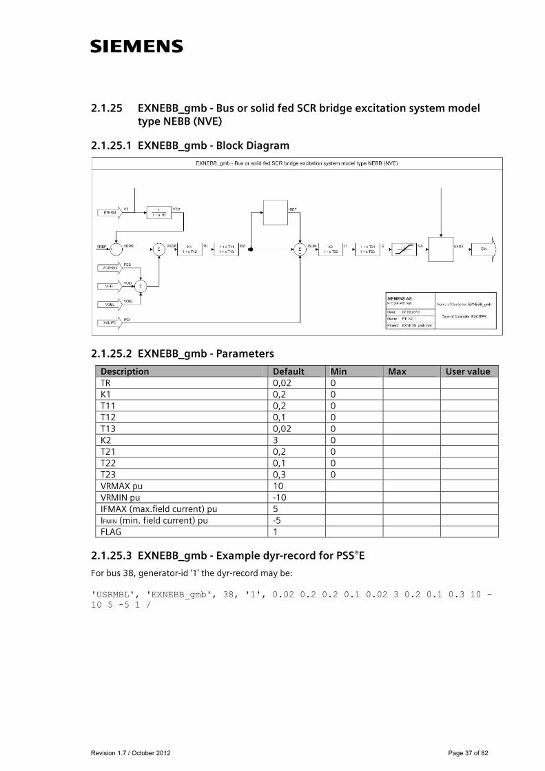
2.1.25 EXNEBB_gmb - Bus or solid fed SCR bridge excitation system model type NEBB (NVE)
2.1.25.1 EXNEBB_gmb - Block Diagram
2.1.25.2 EXNEBB_gmb - Parameters
Description Default Min Max User value TR 0,02 0 K1 0,2 0 T11 0,2 0 T12 0,1 0 T13 0,02 0 K2 3 0 T21 0,2 0 T22 0,1 0 T23 0,3 0 VRMAX pu 10 VRMIN pu -10 IFMAX (max.field current) pu 5 IFMIN (min. field current) pu -5 FLAG 1
2.1.25.3 EXNEBB_gmb - Example dyr-record for PSS®E
For bus 38, generator-id ‘1’ the dyr-record may be: 'USRMBL', 'EXNEBB_gmb', 38, '1', 0.02 0.2 0.2 0.1 0.02 3 0.2 0.1 0.3 10 -10 5 -5 1 /

Revision 1.7 / October 2012 Page 38 of 82
2.1.26 EXNI _gmb - Bus or solid fed SCR bridge excitation system model type NI (NVE)
2.1.26.1 EXNI_gmb – Block Diagram
2.1.26.2 EXNI_gmb – Parameters
Description Default Value Min Max TR (sec) 0,06 0 KA 20 0 TA (sec) 1 0 VRMAX pu 4 VRMIN pu -4 KF 0,019 0 TF1 (sec) 0,64 0 TF2 (sec) 0,32 0
SWITCH 1 0 1 RCFD 10
2.1.26.3 EXNI_gmb - Example dyr-record for PSS®E
For bus 38, generator-id ‘1’ the dyr-record may be: 'USRMBL' , 'EXNI_gmb' ,38, '1', 0.06 20 1 4 -4 0.019 0.64 0.32 1 10 /
Revision 1.7 / October 2012 Page 39 of 82
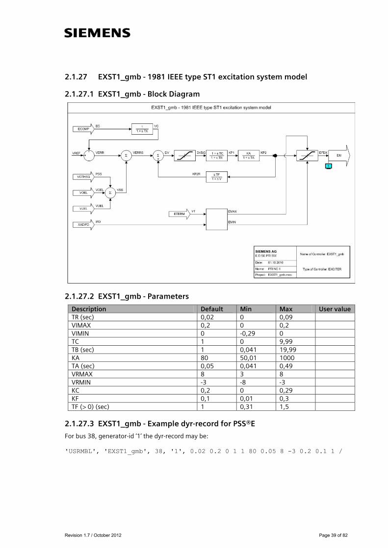
2.1.27 EXST1_gmb - 1981 IEEE type ST1 excitation system model
2.1.27.1 EXST1_gmb - Block Diagram
2.1.27.2 EXST1_gmb - Parameters
Description Default Min Max User value TR (sec) 0,02 0 0,09 VIMAX 0,2 0 0,2 VIMIN 0 -0,29 0 TC 1 0 9,99 TB (sec) 1 0,041 19,99 KA 80 50,01 1000 TA (sec) 0,05 0,041 0,49 VRMAX 8 3 8 VRMIN -3 -8 -3 KC 0,2 0 0,29 KF 0,1 0,01 0,3 TF (> 0) (sec) 1 0,31 1,5
2.1.27.3 EXST1_gmb - Example dyr-record for PSS®E
For bus 38, generator-id ‘1’ the dyr-record may be: 'USRMBL', 'EXST1_gmb', 38, '1', 0.02 0.2 0 1 1 80 0.05 8 -3 0.2 0.1 1 /
Revision 1.7 / October 2012 Page 40 of 82
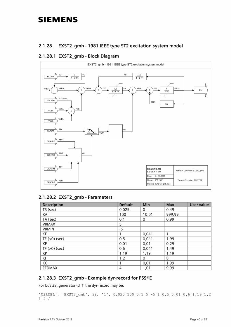
2.1.28 EXST2_gmb - 1981 IEEE type ST2 excitation system model
2.1.28.1 EXST2_gmb - Block Diagram
2.1.28.2 EXST2_gmb - Parameters
Description Default Min Max User value TR (sec) 0,025 0 0,49 KA 100 10,01 999,99 TA (sec) 0,1 0 0,99 VRMAX 5 VRMIN -5 KE 1 0,041 1 TE (>0) (sec) 0,5 0,041 1,99 KF 0,01 0,01 0,29 TF (>0) (sec) 0,6 0,041 1,49 KP 1,19 1,19 1,19 KI 1,2 0 8 KC 1 0,01 1,99 EFDMAX 4 1,01 9,99
2.1.28.3 EXST2_gmb - Example dyr-record for PSS®E
For bus 38, generator-id ‘1’ the dyr-record may be: 'USRMBL', 'EXST2_gmb', 38, '1', 0.025 100 0.1 5 -5 1 0.5 0.01 0.6 1.19 1.2 1 4 /

Revision 1.7 / October 2012 Page 41 of 82
2.1.29 EXST2A_gmb - Modified 1981 IEEE type ST2 excitation system model
2.1.29.1 EXST2A_gmb - Block Diagram
2.1.29.2 EXST2A_gmb - Parameters
Description Default Min Max User value TR (sec) 0,1 0 0,49 KA 10,01 10,01 999,99 TA (sec) 0,1 0 0,99 VRMAX 1,49 0,51 1,49 VRMIN -1,49 -1,49 0,49 KE 0,1 0,041 1 TE (> 0) (sec) 0,3 0,041 1,99 KF 0,01 0,01 0,29 TF (> 0) (sec) 1 0,041 1,49 KP 1,19 1,19 1,19 KI 0 0 8 KC 0,1 0,01 1,99 EFDMAX 4 1,01 9,99
2.1.29.3 EXST2A_gmb - Example dyr-record for PSS®E
For bus 38, generator-id ‘1’ the dyr-record may be: 'USRMBL', 'EXST2A_gmb', 38, '1', 0.1 10.01 0.1 1.49 -1.49 0.1 0.3 0.01 1 1.19 0 0.1 4 /
Revision 1.7 / October 2012 Page 42 of 82
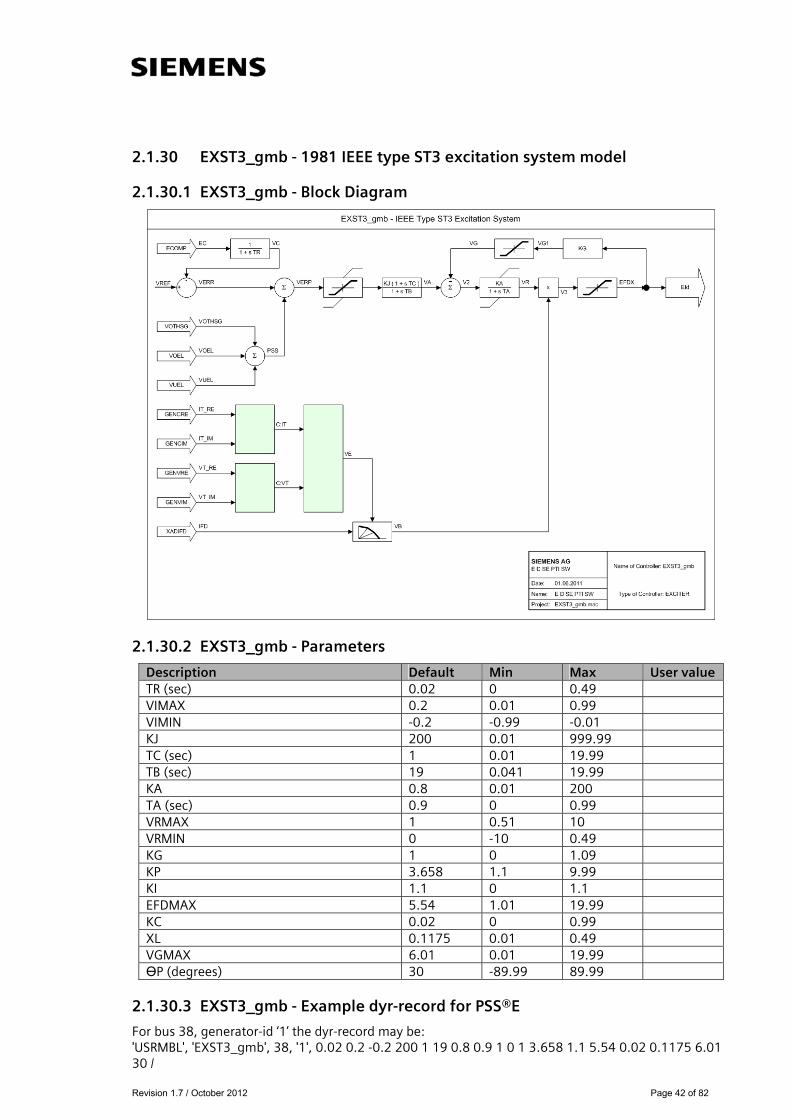
2.1.30 EXST3_gmb - 1981 IEEE type ST3 excitation system model
2.1.30.1 EXST3_gmb - Block Diagram
2.1.30.2 EXST3_gmb - Parameters
Description Default Min Max User value TR (sec) 0.02 0 0.49 VIMAX 0.2 0.01 0.99 VIMIN -0.2 -0.99 -0.01 KJ 200 0.01 999.99 TC (sec) 1 0.01 19.99 TB (sec) 19 0.041 19.99 KA 0.8 0.01 200 TA (sec) 0.9 0 0.99 VRMAX 1 0.51 10 VRMIN 0 -10 0.49 KG 1 0 1.09 KP 3.658 1.1 9.99 KI 1.1 0 1.1 EFDMAX 5.54 1.01 19.99 KC 0.02 0 0.99 XL 0.1175 0.01 0.49 VGMAX 6.01 0.01 19.99 ӨP (degrees) 30 -89.99 89.99
2.1.30.3 EXST3_gmb - Example dyr-record for PSS®E
For bus 38, generator-id ‘1’ the dyr-record may be: 'USRMBL', 'EXST3_gmb', 38, '1', 0.02 0.2 -0.2 200 1 19 0.8 0.9 1 0 1 3.658 1.1 5.54 0.02 0.1175 6.01 30 /
Revision 1.7 / October 2012 Page 43 of 82
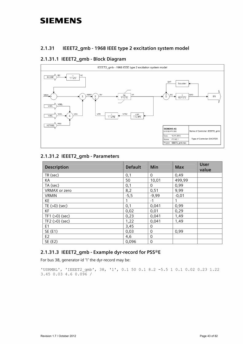
2.1.31 IEEET2_gmb - 1968 IEEE type 2 excitation system model
2.1.31.1 IEEET2_gmb - Block Diagram
2.1.31.2 IEEET2_gmb - Parameters
Description Default Min Max User value
TR (sec) 0,1 0 0,49 KA 50 10,01 499,99 TA (sec) 0,1 0 0,99 VRMAX or zero 8,2 0,51 9,99 VRMIN -5,5 -9,99 -0,01 KE 1 -1 1 TE (>0) (sec) 0,1 0,041 0,99 KF 0,02 0,01 0,29 TF1 (>0) (sec) 0,23 0,041 1,49 TF2 (>0) (sec) 1,22 0,041 1,49 E1 3,45 0 SE (E1) 0,03 0 0,99 E2 4,6 0 SE (E2) 0,096 0
2.1.31.3 IEEET2_gmb - Example dyr-record for PSS®E
For bus 38, generator-id ‘1’ the dyr-record may be: 'USRMBL', 'IEEET2_gmb', 38, '1', 0.1 50 0.1 8.2 -5.5 1 0.1 0.02 0.23 1.22 3.45 0.03 4.6 0.096 /

Revision 1.7 / October 2012 Page 44 of 82
2.1.32 IEEET3_gmb - 1968 IEEE type 3 excitation system model
2.1.32.1 IEEET3_gmb - Block Diagram
2.1.32.2 IEEET3_gmb - Parameters
Description Default Min Max User value TR (sec) 0.01 0 0.49 KA 120 10.01 199.99 TA (sec) 0.05 0 0.99 VRMAX 1.49 0.51 1.49 VRMIN -1.49 -1.49 -0.51 TE (> 0) (sec) 0.5 0.041 1.49 KF 0.03 0.01 0.29 TF (> 0) (sec) 0.5 0.041 1.49 KP (> 0) 1.19 1.19 1.19 KI or zero 2.3 VBMAX (pu voltage base) 3.99 1.01 3.99 KE 1 0 1
2.1.32.3 IEEET3_gmb - Example dyr-record for PSS®E
For bus 38, generator-id ‘1’ the dyr-record may be: 'USRMBL', 'IEEET3_gmb', 38, '1', 0.01 120 0.05 1.49 -1.49 0.5 0.03 0.5 1.19 2.3 3.99 1 /
Revision 1.7 / October 2012 Page 45 of 82
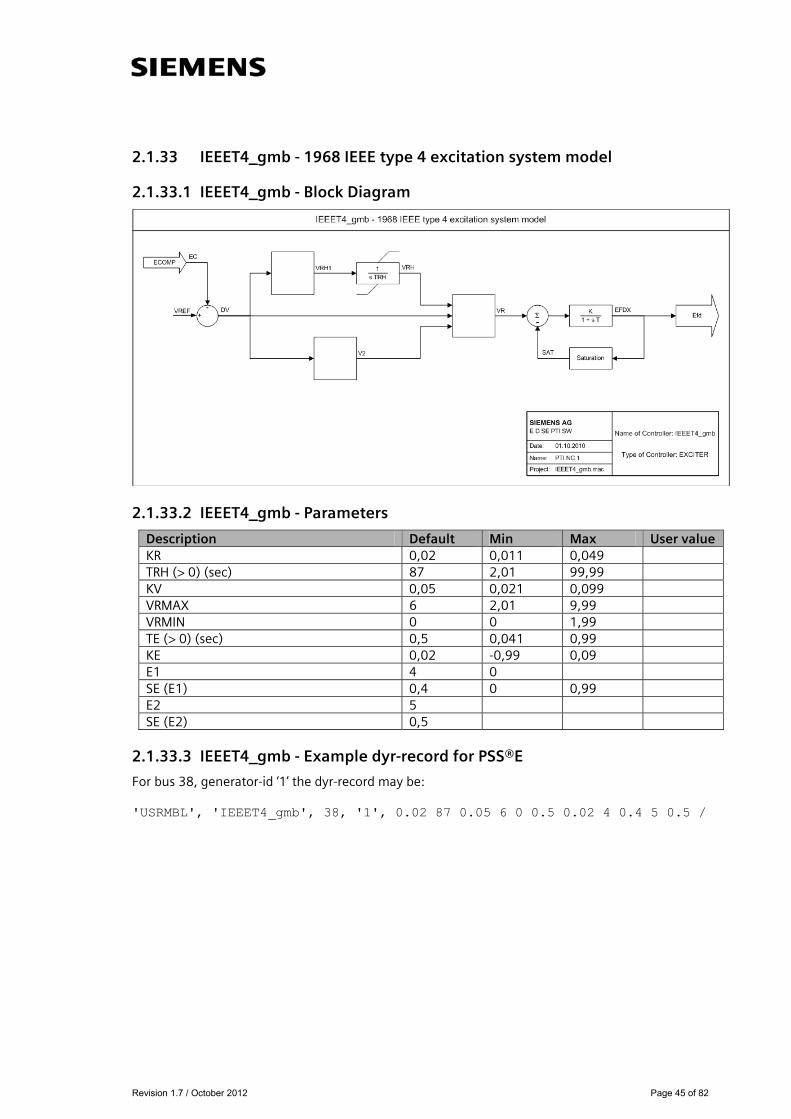
2.1.33 IEEET4_gmb - 1968 IEEE type 4 excitation system model
2.1.33.1 IEEET4_gmb - Block Diagram
2.1.33.2 IEEET4_gmb - Parameters
Description Default Min Max User value KR 0,02 0,011 0,049 TRH (> 0) (sec) 87 2,01 99,99 KV 0,05 0,021 0,099 VRMAX 6 2,01 9,99 VRMIN 0 0 1,99 TE (> 0) (sec) 0,5 0,041 0,99 KE 0,02 -0,99 0,09 E1 4 0 SE (E1) 0,4 0 0,99 E2 5 SE (E2) 0,5
2.1.33.3 IEEET4_gmb - Example dyr-record for PSS®E
For bus 38, generator-id ‘1’ the dyr-record may be: 'USRMBL', 'IEEET4_gmb', 38, '1', 0.02 87 0.05 6 0 0.5 0.02 4 0.4 5 0.5 /
Revision 1.7 / October 2012 Page 46 of 82
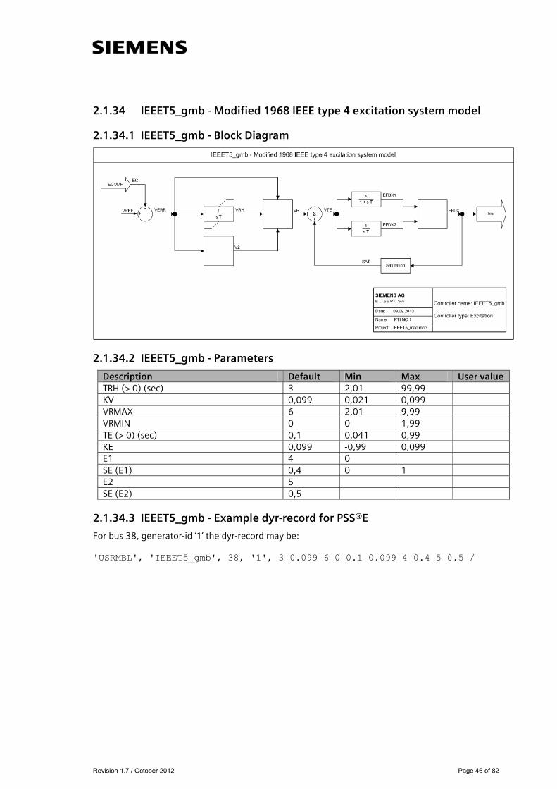
2.1.34 IEEET5_gmb - Modified 1968 IEEE type 4 excitation system model
2.1.34.1 IEEET5_gmb - Block Diagram
2.1.34.2 IEEET5_gmb - Parameters
Description Default Min Max User value TRH (> 0) (sec) 3 2,01 99,99 KV 0,099 0,021 0,099 VRMAX 6 2,01 9,99 VRMIN 0 0 1,99 TE (> 0) (sec) 0,1 0,041 0,99 KE 0,099 -0,99 0,099 E1 4 0 SE (E1) 0,4 0 1 E2 5 SE (E2) 0,5
2.1.34.3 IEEET5_gmb - Example dyr-record for PSS®E
For bus 38, generator-id ‘1’ the dyr-record may be: 'USRMBL', 'IEEET5_gmb', 38, '1', 3 0.099 6 0 0.1 0.099 4 0.4 5 0.5 /
Revision 1.7 / October 2012 Page 47 of 82
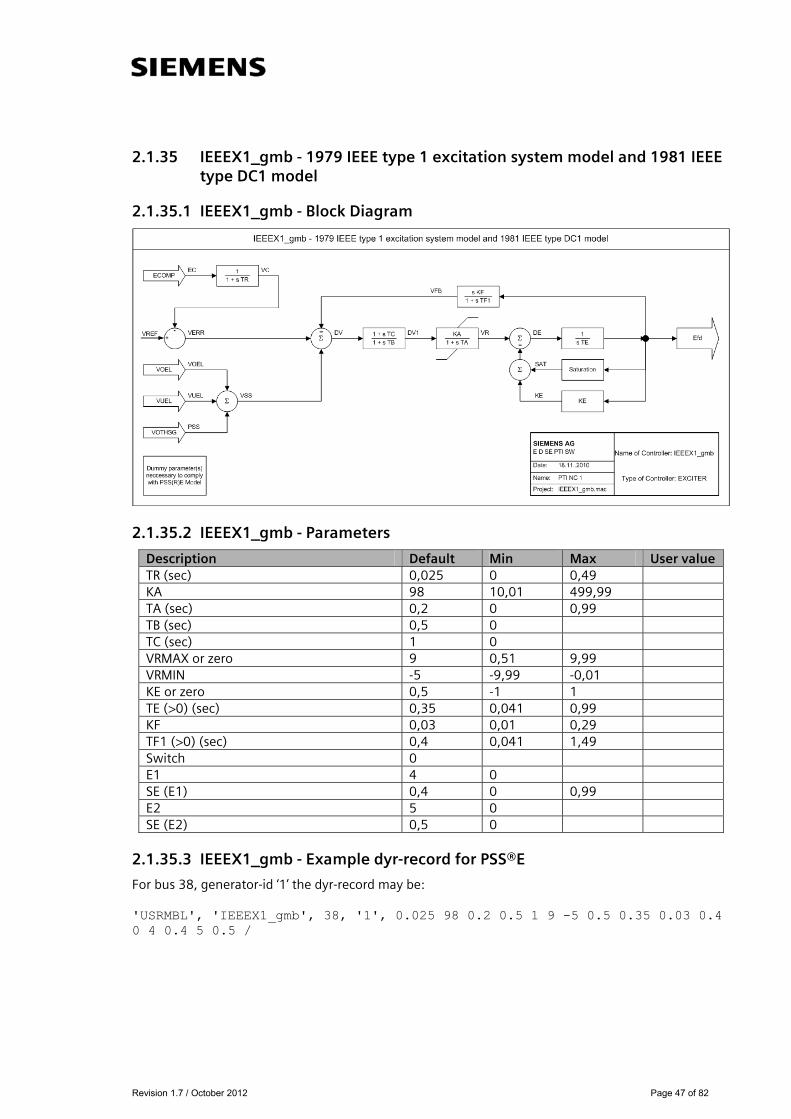
2.1.35 IEEEX1_gmb - 1979 IEEE type 1 excitation system model and 1981 IEEE type DC1 model
2.1.35.1 IEEEX1_gmb - Block Diagram
2.1.35.2 IEEEX1_gmb - Parameters
Description Default Min Max User value TR (sec) 0,025 0 0,49 KA 98 10,01 499,99 TA (sec) 0,2 0 0,99 TB (sec) 0,5 0 TC (sec) 1 0 VRMAX or zero 9 0,51 9,99 VRMIN -5 -9,99 -0,01 KE or zero 0,5 -1 1 TE (>0) (sec) 0,35 0,041 0,99 KF 0,03 0,01 0,29 TF1 (>0) (sec) 0,4 0,041 1,49 Switch 0 E1 4 0 SE (E1) 0,4 0 0,99 E2 5 0 SE (E2) 0,5 0
2.1.35.3 IEEEX1_gmb - Example dyr-record for PSS®E
For bus 38, generator-id ‘1’ the dyr-record may be: 'USRMBL', 'IEEEX1_gmb', 38, '1', 0.025 98 0.2 0.5 1 9 -5 0.5 0.35 0.03 0.4 0 4 0.4 5 0.5 /
Revision 1.7 / October 2012 Page 48 of 82
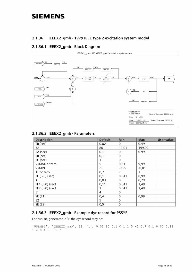
2.1.36 IEEEX2_gmb - 1979 IEEE type 2 excitation system model
2.1.36.1 IEEEX2_gmb - Block Diagram
2.1.36.2 IEEEX2_gmb - Parameters
Description Default Min Max User value TR (sec) 0,02 0 0,49 KA 80 10,01 499,99 TA (sec) 0,1 0 0,99 TB (sec) 0,1 0 TC (sec) 1 0 VRMAX or zero 5 0,51 9,99 VRMIN -5 -9,99 -0,01 KE or zero 0,7 -1 1 TE (> 0) (sec) 0,1 0,041 0,99 KF 0,03 0 0,29 TF1 (> 0) (sec) 0,11 0,041 1,49 TF2 (> 0) (sec) 1 0,041 1,49 E1 4 0 SE (E1) 0,4 0 0,99 E2 5 0 SE (E2) 0,5 0
2.1.36.3 IEEEX2_gmb - Example dyr-record for PSS®E
For bus 38, generator-id ‘1’ the dyr-record may be: 'USRMBL', 'IEEEX2_gmb', 38, '1', 0.02 80 0.1 0.1 1 5 -5 0.7 0.1 0.03 0.11 1 4 0.4 5 0.5 /

Revision 1.7 / October 2012 Page 49 of 82
2.1.37 IEEEX3_gmb - 1979 IEEE type 3 excitation system model
2.1.37.1 IEEEX3_gmb - Block Diagram
2.1.37.2 IEEEX3_gmb - Parameters
Description Default Min Max User value TR (sec) 0,025 0 0,49 KA 37 10,01 199,99 TA (sec) 0,01 0 0,99 VRMAX 1 0,51 1,49 VRMIN -1 -1,49 -0,51 TE (> 0) (sec) 0,2 0,041 1,49 KF 0,2 0,01 0,29 TF (> 0) (sec) 1 0,041 1,49 KP (> 0) 1,19 1,19 1,19 KI or zero 1 0,91 1,09 VBMAX (pu voltage base) 3 1,01 3,99 KE 0,2 0,01 1
2.1.37.3 IEEEX3_gmb - Example dyr-record for PSS®E
For bus 38, generator-id ‘1’ the dyr-record may be: 'USRMBL', 'IEEEX3_gmb', 38, '1', 0.025 37 0.01 1 -1 0.2 0.2 1 1.19 1 3 0.2/

Revision 1.7 / October 2012 Page 50 of 82
2.1.38 IEEEX4_gmb - 1979 IEEE type 4 excitation system, 1981 IEEE type DC3 and 1992 IEEE type DC3A models
2.1.38.1 IEEEX4_gmb - Block Diagram
2.1.38.2 IEEEX4_gmb - Parameters
Description Default Min Max User value TR (sec) 0,1 0,01 0,49 TRH (> 0) (sec) 10 2,01 99,99 KV 0,099 0,021 0,099 VRMAX 2,1 2,01 9,99 VRMIN 0 0 1,99 TE (> 0) (sec) 0,14 0,041 0,99 KE 0,099 -0,99 0,099 E1 4 0 SE (E1) 0,4 0 1 E2 5 0 SE (E2) 0,5 0
2.1.38.3 IEEEX4_gmb - Example dyr-record for PSS®E
For bus 38, generator-id ‘1’ the dyr-record may be: 'USRMBL', 'IEEEX4_gmb', 38, '1', 0.1 10 0.099 2.1 0 0.14 0.099 4 0.4 5 0.5/

Revision 1.7 / October 2012 Page 51 of 82
2.1.39 IEET1A_gmb - Modified 1968 IEEE type 1 excitation system model
2.1.39.1 IEET1A_gmb - Block Diagram
2.1.39.2 IEET1A_gmb – Parameters
Description Default Min Max User value KA 300 10,01 499,99 TA (sec) 0,002 0 0,99 VRMAX 2 0,51 9,99 VRMIN -2 -9,99 -0,01 KE 0,02 -1 1 TE (> 0) (sec) 0,5 0,041 0,99 KF 0,1 0,01 0,29 TF (> 0) (sec) 1 0,041 1,49 EFDMIN 0 0 E1 3 0 SE (E1) 0,3 0 0,99 E2 (EFDMAX) 4 0 SE (EFDMAX) 0,4 0
2.1.39.3 IEET1A_gmb - Example dyr-record for PSS®E
For bus 38, generator-id ‘1’ the dyr-record may be: 'USRMBL', 'IEET1A_gmb', 38, '1', 300 0.002 2 -2 0.02 0.5 0.1 1 0 3 0.3 4 0.4 /

Revision 1.7 / October 2012 Page 52 of 82
2.1.40 IEET1B_gmb - Modified 1968 IEEE type 1 excitation system model
2.1.40.1 IEET1B_gmb - Block Diagram
2.1.40.2 IEET1B_gmb - Parameters
Description Default Min Max User values TR (sec) 0,001 VSMAX 4 VSMIN -4 KA 54 TA1 (sec) 1 VRMAX or zero 3 VRMIN -3 TA2 (sec) 0,01 KF1 1 TF1(> 0) (sec) 5 KE or zero 0,2 TE (>0) (sec) 0,1 E1 4 SE (E1) 0,4 E2 5 SE (E2) 0,5 Switch 0 Xe, compensation 0,8
2.1.40.3 IEET1B_gmb - Example dyr-record for PSS®E
For bus 38, generator-id ‘1’ the dyr-record may be: 'USRMBL' , 'IEET1B_gmb' ,38, '1', 0.001 4 -4 54 1 3 -3 0.01 1 5 0.2 0.1 4 0.4 5 0.5 0 0.8 /

Revision 1.7 / October 2012 Page 53 of 82
2.1.41 IEET5A_gmb - Modified 1968 IEEE type 4 excitation system model
2.1.41.1 IEET5A_gmb - Block Diagram
2.1.41.2 IEET5A_gmb - Parameters
Description Default Min Max User value KA 2,2 0,01 24,99 TRH (sec) 0,1 KV 2 VRMAX 4 2,01 9,99 VRMIN 0 0 1,99 TE (> 0) (sec) 0,05 0,041 0,99 KE 0,099 -0,99 0,099 E1 4 0 SE (E1) 0,4 0 0,99 E2 5 0 SE (E2) 0,5 0 EFDMAX 6 EFDMIN 0
2.1.41.3 IEET5A_gmb - Example dyr-record for PSS®E
For bus 38, generator-id ‘1’ the dyr-record may be: 'USRMBL', 'IEET5A_gmb', 38, '1', 2.2 0.1 2 4 0 0.05 0.099 4 0.4 5 0.5 6 0/
Revision 1.7 / October 2012 Page 54 of 82
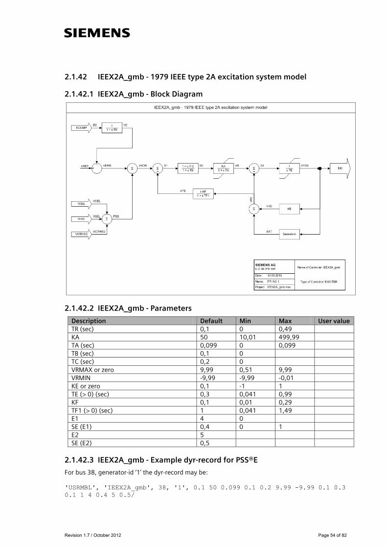
2.1.42 IEEX2A_gmb - 1979 IEEE type 2A excitation system model
2.1.42.1 IEEX2A_gmb - Block Diagram
2.1.42.2 IEEX2A_gmb - Parameters
Description Default Min Max User value TR (sec) 0,1 0 0,49 KA 50 10,01 499,99 TA (sec) 0,099 0 0,099 TB (sec) 0,1 0 TC (sec) 0,2 0 VRMAX or zero 9,99 0,51 9,99 VRMIN -9,99 -9,99 -0,01 KE or zero 0,1 -1 1 TE (> 0) (sec) 0,3 0,041 0,99 KF 0,1 0,01 0,29 TF1 (> 0) (sec) 1 0,041 1,49 E1 4 0 SE (E1) 0,4 0 1 E2 5 SE (E2) 0,5
2.1.42.3 IEEX2A_gmb - Example dyr-record for PSS®E
For bus 38, generator-id ‘1’ the dyr-record may be: 'USRMBL', 'IEEX2A_gmb', 38, '1', 0.1 50 0.099 0.1 0.2 9.99 -9.99 0.1 0.3 0.1 1 4 0.4 5 0.5/

Revision 1.7 / October 2012 Page 55 of 82
2.1.43 IVOEX_gmb - IVO excitation system model
2.1.43.1 IVOEX_gmb - Block Diagram
2.1.43.2 IVOEX_gmb - Parameters
Description Default Min Max User value K1 1 A1 0,5 A2 0,5 T1 0,05 T2 0,1 MAX1 5 MIN1 -5 K3 3 A3 0,5 A4 0,5 T3 0,1 T4 0,1 MAX3 5 MIN3 -5 K5 1 A5 0,5 A6 0,5 T5 0,1 T6 0,1 MAX5 5 MIN5 -2
2.1.43.3 IVOEX_gmb - Example dyr-record for PSS®E
For bus 38, generator-id ‘1’ the dyr-record may be: 'USRMBL', 'IVOEX_gmb', 38, '1', 1 0.5 0.5 0.05 0.1 5 -5 3 0.5 0.5 0.1 0.1 5 -5 1 0.5 0.5 0.1 0.1 5 -2/
Revision 1.7 / October 2012 Page 56 of 82
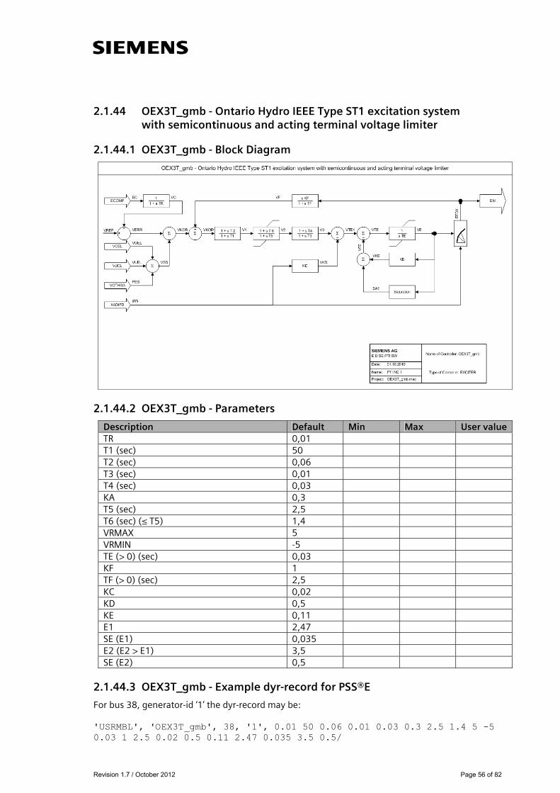
2.1.44 OEX3T_gmb - Ontario Hydro IEEE Type ST1 excitation system with semicontinuous and acting terminal voltage limiter
2.1.44.1 OEX3T_gmb - Block Diagram
2.1.44.2 OEX3T_gmb - Parameters
Description Default Min Max User value TR 0,01 T1 (sec) 50 T2 (sec) 0,06 T3 (sec) 0,01 T4 (sec) 0,03 KA 0,3 T5 (sec) 2,5 T6 (sec) (≤ T5) 1,4 VRMAX 5 VRMIN -5 TE (> 0) (sec) 0,03 KF 1 TF (> 0) (sec) 2,5 KC 0,02 KD 0,5 KE 0,11 E1 2,47 SE (E1) 0,035 E2 (E2 > E1) 3,5 SE (E2) 0,5
2.1.44.3 OEX3T_gmb - Example dyr-record for PSS®E
For bus 38, generator-id ‘1’ the dyr-record may be: 'USRMBL', 'OEX3T_gmb', 38, '1', 0.01 50 0.06 0.01 0.03 0.3 2.5 1.4 5 -5 0.03 1 2.5 0.02 0.5 0.11 2.47 0.035 3.5 0.5/
Revision 1.7 / October 2012 Page 57 of 82
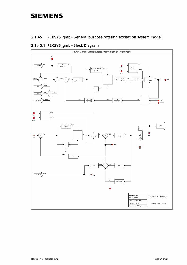
2.1.45 REXSYS_gmb - General purpose rotating excitation system model
2.1.45.1 REXSYS_gmb - Block Diagram

Revision 1.7 / October 2012 Page 58 of 82
2.1.45.2 REXSYS_gmb - Parameters
Description Default Min Max User value TR, voltage transducer time constant (sec) 0,02 0 0,49 KVP, voltage regulator proportional gain 1 0 199,99 KVI, voltage regulator integral gain 3 0 199,99 VIMAX, voltage regulator input limit (pu) 20 0,01 20 TA, voltage regulator time constant (sec) 0,2 0 10 TB1, lag-time constant (sec) 0,03 0 19,99 TC1, lead-time constant (sec) 0,1 0 19,99 TB2, lag-time constant (sec) 1 0 19,99 TC2, lead-time constant (sec) 1 0 19,99 VRMAX, maximum controller output (pu) 19,99 0,51 19,99 VRMIN, maximum controller output (pu) -19,99 -19,99 -0,01 KF, rate feedback gain 0,29 0,01 0,29 TF rate feedback > 0 time constant (sec) 1,49 0,021 1,49 TF1, feedback lead-time constant (sec) 2,4 0 TF2, feedback lag-time constant (sec) 2,8 0 FBF, (0, 1, 2) rate feedback signal flag 0 0 2 KIP, field current regulator proportional gain
0,49 0 0,49
KII, field current regualtor integral gain 0,49 0 0,49 TP, field current bridge time constant (sec) 0,9 0 VFMAX, maximum exciter field current (pu) 99,99 0,51 99,99 VFMIN, minimum exciter field current (pu) -99,99 -99,99 -0,01 KH, field voltage controller feedback gain 1,3 -10 10 KE, exciter field proportional constant 1 -10 10 TE, exciter field time constant (sec > 0) 0,23 0,021 9,99 KC, rectifier regulation factor (pu) 0,5 1 KD, exciter regulation factor (pu) 0,03 2 E1, exciter flux at knee of curve (pu) 4 0 SE (E1), saturation factor at knee 0,4 0 1 E2, maximum exciter (pu) 5 0 SE (E2), saturation factor at maximum flux 0,5 0 FLIMF, power supply limit factor 1 0
2.1.45.3 REXSYS_gmb - Example dyr-record for PSS®E
For bus 38, generator-id ‘1’ the dyr-record may be: 'USRMBL', 'REXSYS_gmb', 38, '1', 0.02 1 3 20 0.2 0.03 0.1 1 1 19.99 -19.99 0.29 1.49 2.4 2.8 0 0.49 0.49 0.9 99.99 -99.99 1.3 1 0.23 0.5 0.03 4 0.4 5 0.5 1/
Revision 1.7 / October 2012 Page 59 of 82
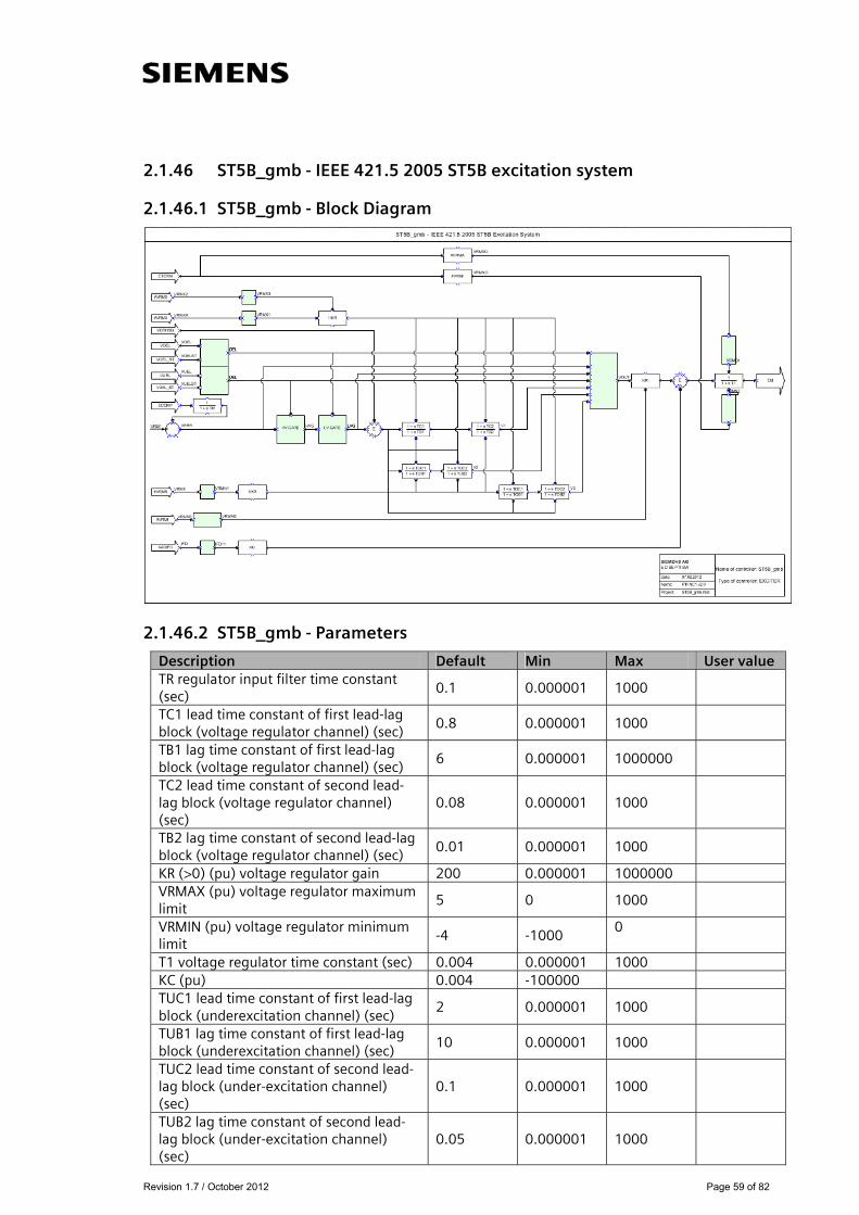
2.1.46 ST5B_gmb - IEEE 421.5 2005 ST5B excitation system
2.1.46.1 ST5B_gmb - Block Diagram
2.1.46.2 ST5B_gmb - Parameters
Description Default Min Max User value TR regulator input filter time constant (sec)
0.1 0.000001 1000
TC1 lead time constant of first lead-lag block (voltage regulator channel) (sec)
0.8 0.000001 1000
TB1 lag time constant of first lead-lag block (voltage regulator channel) (sec)
6 0.000001 1000000
TC2 lead time constant of second lead-lag block (voltage regulator channel) (sec)
0.08 0.000001 1000
TB2 lag time constant of second lead-lag block (voltage regulator channel) (sec)
0.01 0.000001 1000
KR (>0) (pu) voltage regulator gain 200 0.000001 1000000 VRMAX (pu) voltage regulator maximum limit
5 0 1000
VRMIN (pu) voltage regulator minimum limit
-4 -1000 0
T1 voltage regulator time constant (sec) 0.004 0.000001 1000 KC (pu) 0.004 -100000 TUC1 lead time constant of first lead-lag block (underexcitation channel) (sec)
2 0.000001 1000
TUB1 lag time constant of first lead-lag block (underexcitation channel) (sec)
10 0.000001 1000
TUC2 lead time constant of second lead-lag block (under-excitation channel) (sec)
0.1 0.000001 1000
TUB2 lag time constant of second lead-lag block (under-excitation channel) (sec)
0.05 0.000001 1000
Revision 1.7 / October 2012 Page 60 of 82
TOC1 lead time constant of first lead-lag block (overexcitation channel) (sec)
0.1 0.000001 1000
TOB1 lag time constant of first lead-lag block (overexcitation channel) (sec)
2 0.000001 1000
TOC2 lead time constant of second lead-lag block (over-excitation channel) (sec)
0.08 0.000001 1000
TOB2 lag time constant of second lead-lag block (overexcitation channel) (sec)
0.08 0.000001 1000
VUEL1 0 0 1 VOEL1 0 0 1
2.1.46.3 ST5B_gmb - Example dyr-record for PSS®E
For bus 38, generator-id ‘1’ the dyr-record may be: 'USRMBL', 'ST5B_gmb', 38, '1', 0.1 0.8 6 0.08 0.01 200 5 -4 0.004 0.004 2 10 0.1 0.05 0.1 2 0.08 0.08 0 0/
Revision 1.7 / October 2012 Page 61 of 82
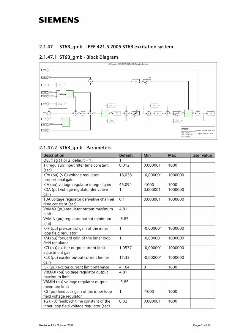
2.1.47 ST6B_gmb - IEEE 421.5 2005 ST6B excitation system
2.1.47.1 ST6B_gmb - Block Diagram
2.1.47.2 ST6B_gmb - Parameters
Description Default Min Max User value OEL flag (1 or 2, default = 1) 1 TR regulator input filter time constant (sec)
0,012 0,000001 1000
KPA (pu) (> 0) voltage regulator proportional gain
18,038 -0,000001 1000000
KIA (pu) voltage regulator integral gain 45,094 -1000 1000 KDA (pu) voltage regulator derivative gain
1 0,000001 1000000
TDA voltage regulator derivative channel time constant (sec)
0,1 0,000001 1000000
VAMAX (pu) regulator output maximum limit
4,81
VAMIN (pu) regulator output minimum limit
-3,85
KFF (pu) pre-control gain of the inner loop field regulator
1 -0,000001 1000000
KM (pu) forward gain of the inner loop field regulator
1 -0,000001 1000000
KCI (pu) exciter output current limit adjustment gain
1,0577 -0,000001 1000000
KLR (pu) exciter output current limiter gain
17,33 -0,000001 1000000
ILR (pu) exciter current limit reference 4,164 0 1000 VRMAX (pu) voltage regulator output maximum limit
4,81
VRMIN (pu) voltage regulator output minimum limit
-3,85
KG (pu) feedback gain of the inner loop field voltage regulator
1 -1000 1000
TG (> 0) feedback time constant of the inner loop field voltage regulator (sec)
0,02 0,000001 1000

Revision 1.7 / October 2012 Page 62 of 82
2.1.47.3 ST6B_gmb - Example dyr-record for PSS®E
For bus 38, generator-id ‘1’ the dyr-record may be: 'USRMBL', 'ST6B_gmb', 38, '1', 1 0.012 18.038 45.094 1 0.1 4.81 -3.85 1 1 1.0577 17.33 4.164 4.81 -3.85 1 0.02/
Revision 1.7 / October 2012 Page 63 of 82
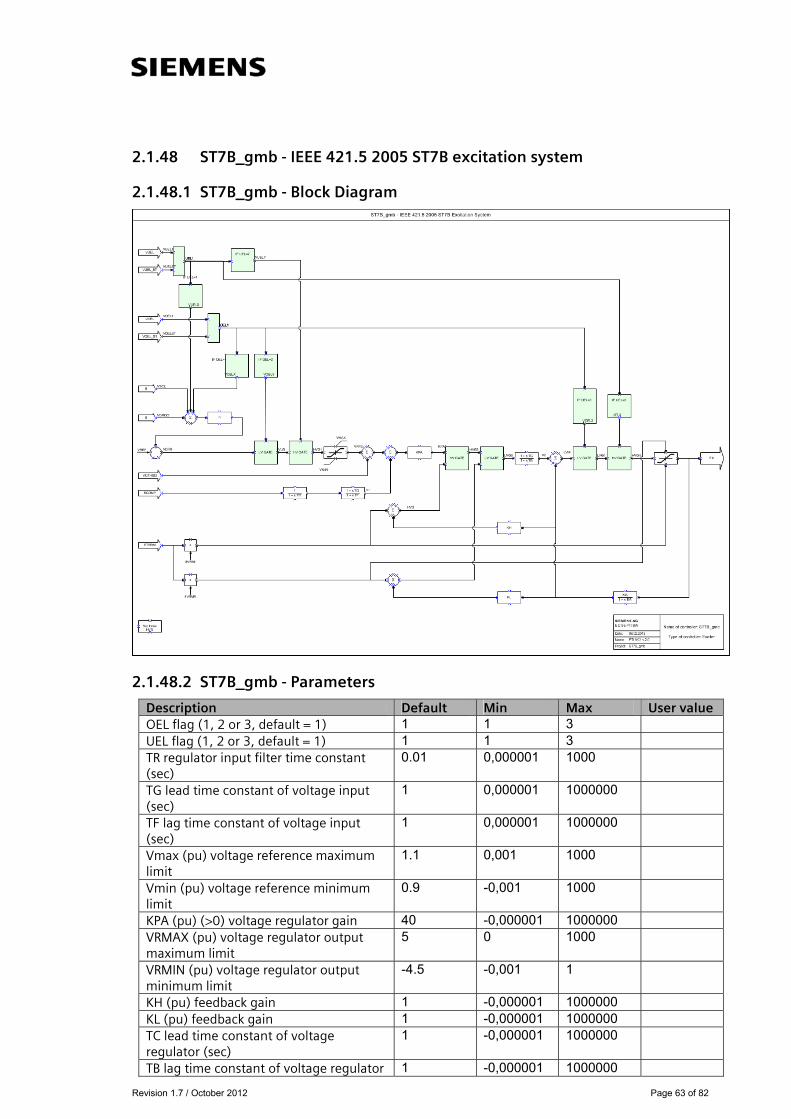
2.1.48 ST7B_gmb - IEEE 421.5 2005 ST7B excitation system
2.1.48.1 ST7B_gmb - Block Diagram
2.1.48.2 ST7B_gmb - Parameters
Description Default Min Max User value OEL flag (1, 2 or 3, default = 1) 1 1 3 UEL flag (1, 2 or 3, default = 1) 1 1 3 TR regulator input filter time constant (sec)
0.01 0,000001 1000
TG lead time constant of voltage input (sec)
1 0,000001 1000000
TF lag time constant of voltage input (sec)
1 0,000001 1000000
Vmax (pu) voltage reference maximum limit
1.1 0,001 1000
Vmin (pu) voltage reference minimum limit
0.9 -0,001 1000
KPA (pu) (>0) voltage regulator gain 40 -0,000001 1000000 VRMAX (pu) voltage regulator output maximum limit
5 0 1000
VRMIN (pu) voltage regulator output minimum limit
-4.5 -0,001 1
KH (pu) feedback gain 1 -0,000001 1000000 KL (pu) feedback gain 1 -0,000001 1000000 TC lead time constant of voltage regulator (sec)
1 -0,000001 1000000
TB lag time constant of voltage regulator 1 -0,000001 1000000

Revision 1.7 / October 2012 Page 64 of 82
(sec) KIA (pu) (>0) gain of the first order feedback block
1 -0,000001 1000000
TIA (>0) time constant of the first order feedback block (sec)
3 -0,000001 1000000
OELE (0 or 1, 0=no OEL, 1=OEL exist) 0 0 1 UELE (0 or 1, 0=no UEL, 1= UEL exist) 0 0 1
2.1.48.3 ST7B_gmb - Example dyr-record for PSS®E
For bus 38, generator-id ‘1’ the dyr-record may be: 'USRMBL', 'ST7B_gmb', 38, '1', 1 1 0.01 1 1 1.1 0.9 40 5 -4.5 1 1 1 1 1 3 0 0/

Revision 1.7 / October 2012 Page 65 of 82
2.1.49 URST5T_gmb - IEEE proposed type ST5B excitation system
2.1.49.1 URST5T_gmb - Block Diagram
2.1.49.2 URST5T_gmb - Parameters
Description Default Min Max User value Tr (sec) 0,025 TC1 (sec) 0,1 TB1 (sec) 0,2 TC2 (sec) 1 TB2 (sec) 1 KR 1 VRMAX 10 VRMIN -10 T1 0,58 KC 0,3
2.1.49.3 URST5T_gmb - Example dyr-record for PSS®E
For bus 38, generator-id ‘1’ the dyr-record may be: 'USRMBL', 'URST5T_gmb', 38, '1', 0.025 0.1 0.2 1 1 1 10 -10 0.58 0.3/
Revision 1.7 / October 2012 Page 66 of 82
2.2 Governors (GOV)
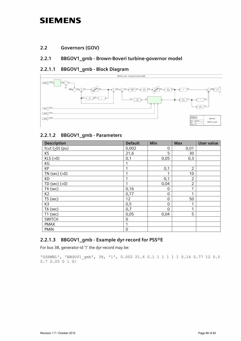
2.2.1 BBGOV1_gmb - Brown-Boveri turbine-governor model
2.2.1.1 BBGOV1_gmb - Block Diagram
2.2.1.2 BBGOV1_gmb - Parameters
2.2.1.3 BBGOV1_gmb - Example dyr-record for PSS®E
For bus 38, generator-id ‘1’ the dyr-record may be: 'USRMBL', 'BBGOV1_gmb', 38, '1', 0.002 21.6 0.1 1 1 1 1 1 0.16 0.77 12 0.5 0.7 0.05 0 1 0/
Description Default Min Max User value fcut (>0) (pu) 0,002 0 0,01 KS 21,6 5 30 KLS (>0) 0,1 0,05 0,3 KG 1 KP 1 0,1 2 TN (sec) (>0) 1 1 10 KD 1 0,1 2 TD (sec) (>0) 1 0,04 2 T4 (sec) 0,16 0 1 K2 0,77 0 1 T5 (sec) 12 0 50 K3 0,5 0 1 T6 (sec) 0,7 0 1 T1 (sec) 0,05 0,04 5 SWITCH 0 PMAX 1 PMIN 0

Revision 1.7 / October 2012 Page 67 of 82
2.2.2 CRCMGV_gmb - Cross compound turbine-governor model
2.2.2.1 CRCMGV_gmb - Block Diagram
2.2.2.2 CRCMGV_gmb - Parameters
2.2.2.3 CRCMGV_gmb - Example dyr-record for PSS®E
For bus 38, generator-id ‘1’ the dyr-record may be: 'USRMBL', 'CRCMGV_gmb', 38, '1', 38 1 1 0.02 1.2 0.8 0.6 0.3 6.1 0 1 0.02 1.2 0.8 0.6 0.3 6.1 0/
Description Default Min Max User value JBUS-Dummy 38 M-Dummy 1 PMAX (HP) 1 0,51 1,19 R (HP) 0,02 0,01 0,099 T1(HP>0) 1,2 0,041 T3(HP>0) 0,8 0,041 T4(HP>0) 0,6 0,041 T5(HP>0) 0,3 0,041 F (HP) 6,1 DH (HP) 0 0 0 PMAX (LP) 1 RL (LP) 0,02 T1L (LP) (>0) 1,2 T3L (LP) (>0) 0,8 T4L (LP) (>0) 0,6 T5L (LP) (>0) 0,3 F (LP) 6,1 DH (LP) 0
Revision 1.7 / October 2012 Page 68 of 82
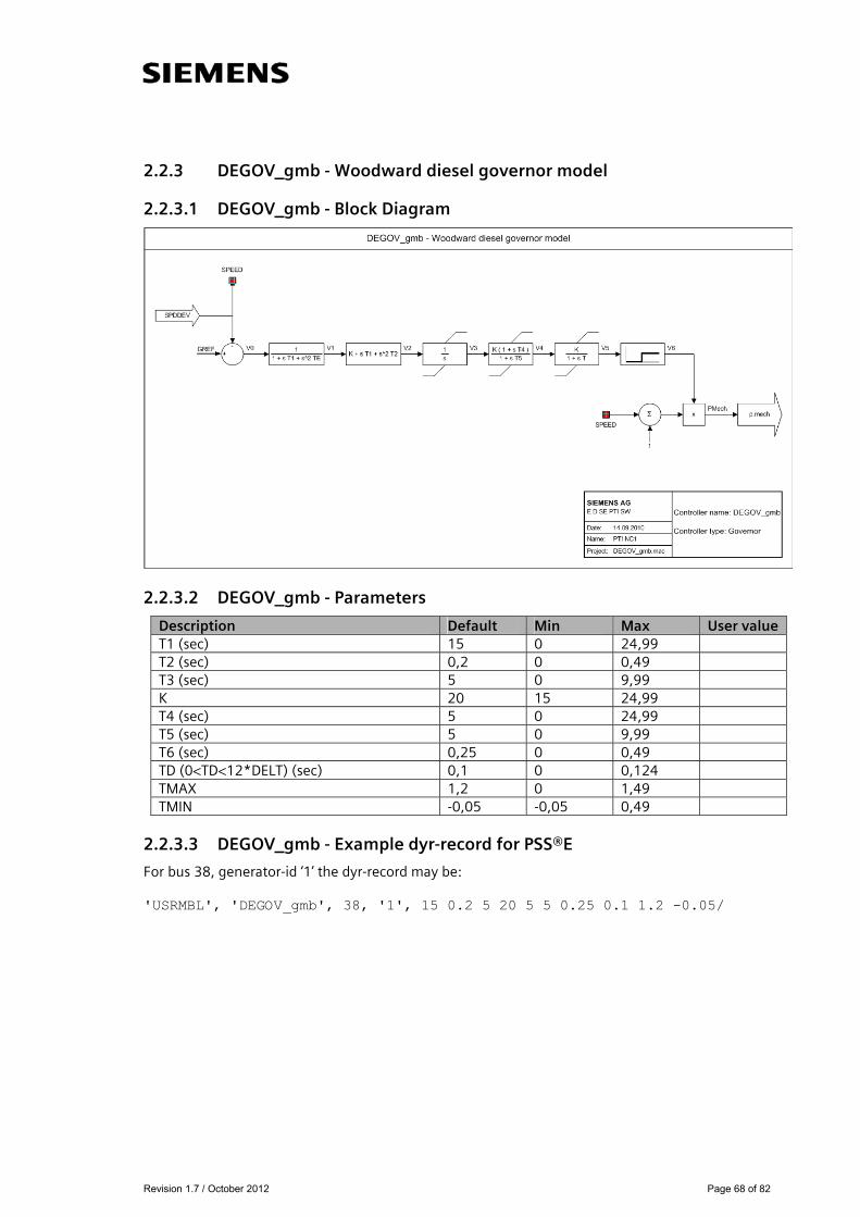
2.2.3 DEGOV_gmb - Woodward diesel governor model
2.2.3.1 DEGOV_gmb - Block Diagram
2.2.3.2 DEGOV_gmb - Parameters
Description Default Min Max User value T1 (sec) 15 0 24,99 T2 (sec) 0,2 0 0,49 T3 (sec) 5 0 9,99 K 20 15 24,99 T4 (sec) 5 0 24,99 T5 (sec) 5 0 9,99 T6 (sec) 0,25 0 0,49 TD (0<TD<12*DELT) (sec) 0,1 0 0,124 TMAX 1,2 0 1,49 TMIN -0,05 -0,05 0,49
2.2.3.3 DEGOV_gmb - Example dyr-record for PSS®E
For bus 38, generator-id ‘1’ the dyr-record may be: 'USRMBL', 'DEGOV_gmb', 38, '1', 15 0.2 5 20 5 5 0.25 0.1 1.2 -0.05/
Revision 1.7 / October 2012 Page 69 of 82
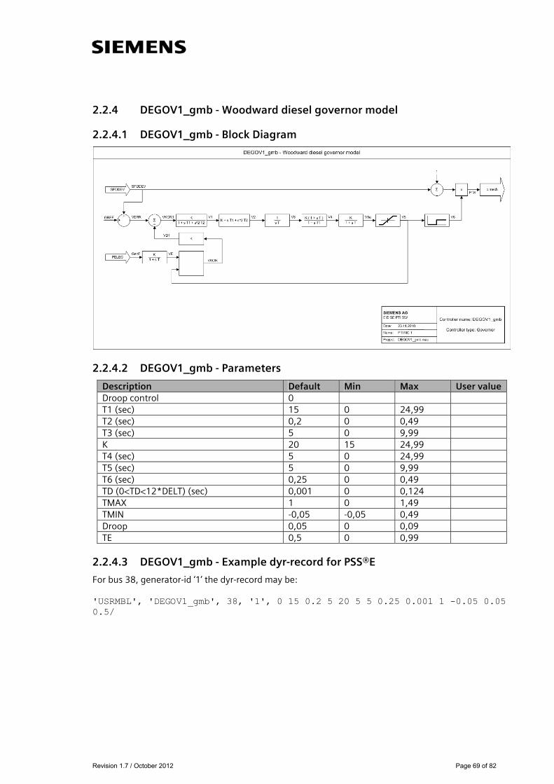
2.2.4 DEGOV1_gmb - Woodward diesel governor model
2.2.4.1 DEGOV1_gmb - Block Diagram
2.2.4.2 DEGOV1_gmb - Parameters
Description Default Min Max User value Droop control 0 T1 (sec) 15 0 24,99 T2 (sec) 0,2 0 0,49 T3 (sec) 5 0 9,99 K 20 15 24,99 T4 (sec) 5 0 24,99 T5 (sec) 5 0 9,99 T6 (sec) 0,25 0 0,49 TD (0<TD<12*DELT) (sec) 0,001 0 0,124 TMAX 1 0 1,49 TMIN -0,05 -0,05 0,49 Droop 0,05 0 0,09 TE 0,5 0 0,99
2.2.4.3 DEGOV1_gmb - Example dyr-record for PSS®E
For bus 38, generator-id ‘1’ the dyr-record may be: 'USRMBL', 'DEGOV1_gmb', 38, '1', 0 15 0.2 5 20 5 5 0.25 0.001 1 -0.05 0.05 0.5/

Revision 1.7 / October 2012 Page 70 of 82
2.2.5 GAST_gmb - Gas turbine-governor model
2.2.5.1 GAST_gmb - Block Diagram
2.2.5.2 GAST_gmb - Parameters
2.2.5.3 GAST_gmb - Example dyr-record for PSS®E
For bus 38, generator-id ‘1’ the dyr-record may be: 'USRMBL', 'GAST_gmb', 38, '1', 0.047 0.4 0.1 3 0.85 0 0/
Description Default Min Max User value R (speed droop) 0,047 0,01 0,099 T1 (>0) (sec) 0,4 0,041 0,49 T2 (>0) (sec) 0,1 0,041 0,49 T3 (>0) (sec) 3 0,041 4,99 Ambient temperature load limit, AT 0,85 0,01 1 KT 2 0,01 4,99 VMAX 0,85 0,51 1,19 VMIN 0 0 0,99 Dturb 0 0 0,49
Revision 1.7 / October 2012 Page 71 of 82
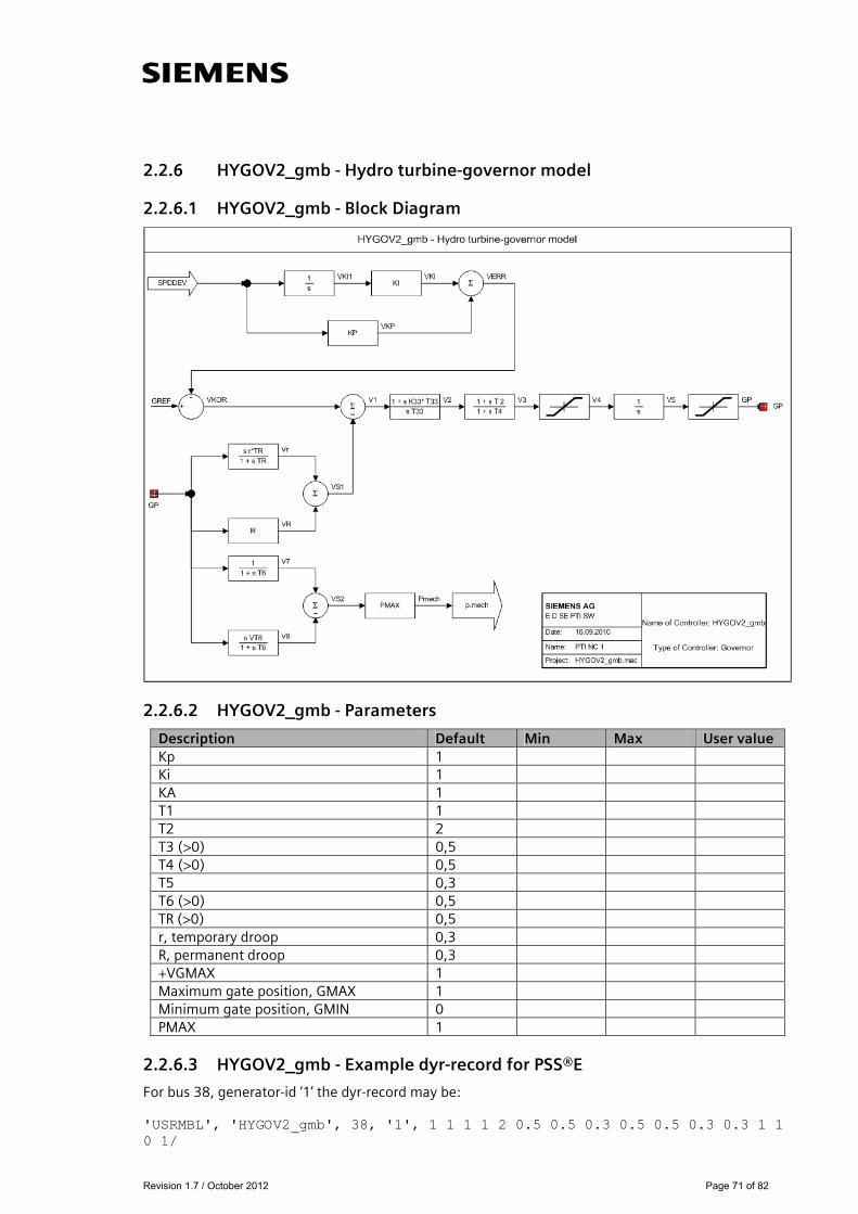
2.2.6 HYGOV2_gmb - Hydro turbine-governor model
2.2.6.1 HYGOV2_gmb - Block Diagram
2.2.6.2 HYGOV2_gmb - Parameters
2.2.6.3 HYGOV2_gmb - Example dyr-record for PSS®E
For bus 38, generator-id ‘1’ the dyr-record may be: 'USRMBL', 'HYGOV2_gmb', 38, '1', 1 1 1 1 2 0.5 0.5 0.3 0.5 0.5 0.3 0.3 1 1 0 1/
Description Default Min Max User value Kp 1 Ki 1 KA 1 T1 1 T2 2 T3 (>0) 0,5 T4 (>0) 0,5 T5 0,3 T6 (>0) 0,5 TR (>0) 0,5 r, temporary droop 0,3 R, permanent droop 0,3 +VGMAX 1 Maximum gate position, GMAX 1 Minimum gate position, GMIN 0 PMAX 1
Revision 1.7 / October 2012 Page 72 of 82
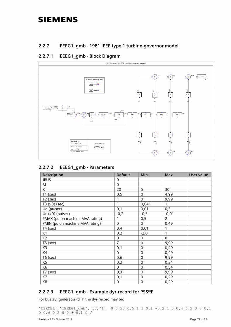
2.2.7 IEEEG1_gmb - 1981 IEEE type 1 turbine-governor model
2.2.7.1 IEEEG1_gmb - Block Diagram
2.2.7.2 IEEEG1_gmb - Parameters
2.2.7.3 IEEEG1_gmb - Example dyr-record for PSS®E
For bus 38, generator-id ‘1’ the dyr-record may be: 'USRMBL','IEEEG1_gmb', 38,'1', 0 0 20 0.5 1 1 0.1 -0.2 1 0 0.4 0.2 0 7 0.1 0 0.6 0.2 0 0.3 0.1 0 /
Description Default Min Max User value JBUS 0 M 0 K 20 5 30 T1 (sec) 0,5 0 4,99 T2 (sec) 1 0 9,99 T3 (>0) (sec) 1 0,041 1 Uo (pu/sec) 0,1 0,01 0,3 Uc (<0) (pu/sec) -0,2 -0,3 -0,01 PMAX (pu on machine MVA rating) 1 0,5 2 PMIN (pu on machine MVA rating) 0 0 0,49 T4 (sec) 0,4 0,01 1 K1 0,2 -2,0 1 K2 0 0 0 T5 (sec) 7 0 9,99 K3 0,1 0 0,49 K4 0 0 0,49 T6 (sec) 0,6 0 9,99 K5 0,2 0 0,34 K6 0 0 0,54 T7 (sec) 0,3 0 9,99 K7 0,1 0 0,29 K8 0 0 0,29
Revision 1.7 / October 2012 Page 73 of 82
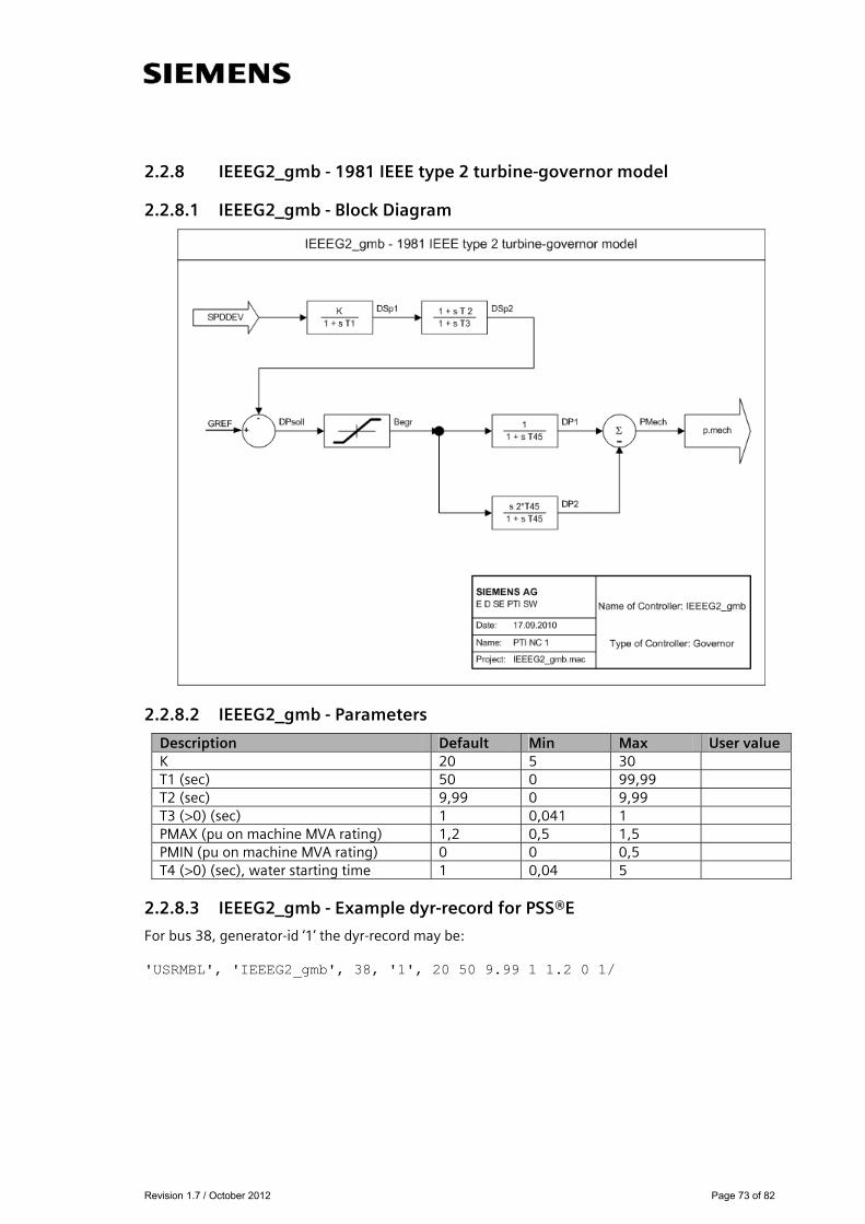
2.2.8 IEEEG2_gmb - 1981 IEEE type 2 turbine-governor model
2.2.8.1 IEEEG2_gmb - Block Diagram
2.2.8.2 IEEEG2_gmb - Parameters
2.2.8.3 IEEEG2_gmb - Example dyr-record for PSS®E
For bus 38, generator-id ‘1’ the dyr-record may be: 'USRMBL', 'IEEEG2_gmb', 38, '1', 20 50 9.99 1 1.2 0 1/
Description Default Min Max User value K 20 5 30 T1 (sec) 50 0 99,99 T2 (sec) 9,99 0 9,99 T3 (>0) (sec) 1 0,041 1 PMAX (pu on machine MVA rating) 1,2 0,5 1,5 PMIN (pu on machine MVA rating) 0 0 0,5 T4 (>0) (sec), water starting time 1 0,04 5
Revision 1.7 / October 2012 Page 74 of 82
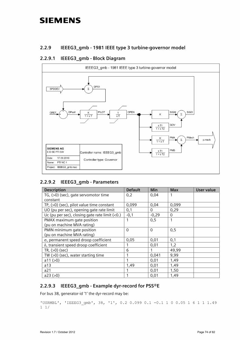
2.2.9 IEEEG3_gmb - 1981 IEEE type 3 turbine-governor model
2.2.9.1 IEEEG3_gmb - Block Diagram
2.2.9.2 IEEEG3_gmb - Parameters
2.2.9.3 IEEEG3_gmb - Example dyr-record for PSS®E
For bus 38, generator-id ‘1’ the dyr-record may be: 'USRMBL', 'IEEEG3_gmb', 38, '1', 0.2 0.099 0.1 -0.1 1 0 0.05 1 6 1 1 1.49 1 1/
Description Default Min Max User value TG, (>0) (sec), gate servomotor time constant
0,2 0,04 1
TP, (>0) (sec), pilot value time constant 0,099 0,04 0,099 UO (pu per sec), opening gate rate limit 0,1 0 0,29 Uc (pu per sec), closing gate rate limit (<0.) -0,1 -0,29 0 PMAX maximum gate position (pu on machine MVA rating)
1 0,5 1
PMIN minimum gate position (pu on machine MVA rating)
0 0 0,5
, permanent speed droop coefficient 0,05 0,01 0,1 , transient speed droop coefficient 1 0,01 1,2 TR, (>0) (sec) 6 1 49,99 TW (>0) (sec), water starting time 1 0,041 9,99 a11 (>0) 1 0,01 1,49 a13 1,49 0,01 1,49 a21 1 0,01 1,50 a23 (>0) 1 0,01 1,49

Revision 1.7 / October 2012 Page 75 of 82
2.2.10 IEESGO_gmb - 1973 IEEE standard turbine-governor model
2.2.10.1 IEESGO_gmb - Block Diagram
2.2.10.2 IEESGO_gmb - Parameters
2.2.10.3 IEESGO_gmb - Example dyr-record for PSS®E
For bus 38, generator-id ‘1’ the dyr-record may be: 'USRMBL', 'IEESGO_gmb', 38, '1', 0.1 0.2 0.1 1 0.5 0.5 20 0.8 1 1.1 0 /
Description Default Min Max User value T1, controller lag (sec) 0,1 0 99,99 T2, controller lead compensation (sec) 0,2 0 9,99 T3, governor lag (>0) (sec) 0,1 0,041 1 T4, delay due to steam inlet volumes associated with steam chest and inlet piping (sec)
1,0 0 1
T5, reheater delay including hot and cold leads (sec)
0,5 0 50
T6, delay due to IP-LP turbine, crossover pipes, and LP end hoods (sec)
0,5 0 1
K1, 1/per unit regulation 20 5 30 K2, fraction 0,8 0 3 K3, fraction 1 -1 1 PMAX, upper power limit 1,1 0,5 1,5 PMIN, lower power limit 0 0 0,5
Revision 1.7 / October 2012 Page 76 of 82
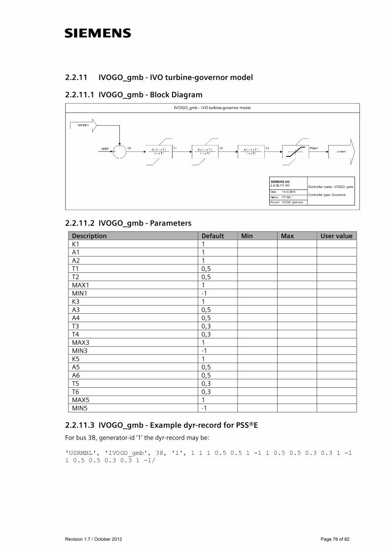
2.2.11 IVOGO_gmb - IVO turbine-governor model
2.2.11.1 IVOGO_gmb - Block Diagram
2.2.11.2 IVOGO_gmb - Parameters
Description Default Min Max User value K1 1 A1 1 A2 1 T1 0,5 T2 0,5 MAX1 1 MIN1 -1 K3 1 A3 0,5 A4 0,5 T3 0,3 T4 0,3 MAX3 1 MIN3 -1 K5 1 A5 0,5 A6 0,5 T5 0,3 T6 0,3 MAX5 1 MIN5 -1
2.2.11.3 IVOGO_gmb - Example dyr-record for PSS®E
For bus 38, generator-id ‘1’ the dyr-record may be: 'USRMBL', 'IVOGO_gmb', 38, '1', 1 1 1 0.5 0.5 1 -1 1 0.5 0.5 0.3 0.3 1 -1 1 0.5 0.5 0.3 0.3 1 -1/
Revision 1.7 / October 2012 Page 77 of 82
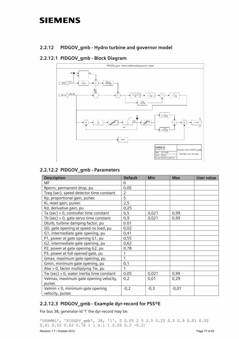
2.2.12 PIDGOV_gmb - Hydro turbine and governor model
2.2.12.1 PIDGOV_gmb - Block Diagram
2.2.12.2 PIDGOV_gmb - Parameters
Description Default Min Max User value MF 0 Rperm, permanent drop, pu 0,05 Treg (sec), speed detector time constant 2 Kp, proportional gain, pu/sec 5 Ki, reset gain, pu/sec 2,5 Kd, derivative gain, pu 0,25 Ta (sec) > 0, controller time constant 0,5 0,021 0,99 Tb (sec) > 0, gate servo time constant 0,9 0,021 0,99 Dturb, turbine damping factor, pu 0.01 G0, gate opening at speed no load, pu 0,02 G1, intermediate gate opening, pu 0,41 P1, power at gate opening G1, pu 0,55 G2, intermediate gate opening, pu 0,62 P2, power at gate opening G2, pu 0,78 P3, power at full opened gate, pu 1 Gmax, maximum gate opening, pu 1 Gmin, minimum gate opening, pu 0,1 Atw > 0, factor multiplying Tw, pu 1 Tw (sec) > 0, water inertia time constant 0,05 0,021 0,99 Velmax, maximum gate opening velocity, pu/sec
0,2 0,01 0,29
Velmin < 0, minimum gate opening velocity, pu/sec
-0,2 -0,3 -0,01
2.2.12.3 PIDGOV_gmb - Example dyr-record for PSS®E
For bus 38, generator-id ‘1’ the dyr-record may be: 'USRMBL', 'PIDGOV_gmb', 38, '1', 0 0.05 2 5 2.5 0.25 0.5 0.9 0.01 0.02 0.41 0.55 0.62 0.78 1 1 0.1 1 0.05 0.2 -0.2/

Revision 1.7 / October 2012 Page 78 of 82
2.2.13 TGOV2_gmb - Steam turbine-governor model with fast valving
2.2.13.1 TGOV2_gmb - Block Diagram
2.2.13.2 TGOV2_gmb - Parameters
2.2.13.3 TGOV2_gmb - Example dyr-record for PSS®E
For bus 38, generator-id ‘1’ the dyr-record may be: 'USRMBL', 'TGOV2_gmb', 38, '1', 0.099 0.3 1 0 0.3 2 0 0.2 0.1 0.3 1.5 /
Description Default Min Max User value R (pu) 0,099 0 0,099 T1 (>0) (sec) 0,3 0,041 0,49 VMAX (pu) 1 0,51 1,19 VMIN (pu) 0 0 0,099 K (pu) 0,3 0,099 0,49 T3 (>0) (sec) 2 1,01 9,99 Dt (pu) 0 0 0,49 Tt (>0) (sec) 0,2 0,041 0,49 TA 0.1 TB 0.3 TC 1.5

Revision 1.7 / October 2012 Page 79 of 82
2.2.14 TGOV3_gmb - Modified IEEE type 1 turbine-governor model with fast valving
2.2.14.1 TGOV3_gmb - Block Diagram
2.2.14.2 TGOV3_gmb - Parameters
2.2.14.3 TGOV3_gmb - Example dyr-record for PSS®E
For bus 38, generator-id ‘1’ the dyr-record may be: 'USRMBL', 'TGOV3_gmb', 38, '1', 20 0.9 0.2 0.5 0.1 -0.1 1 0 0.2 0.5 0.2 0.3 0.2 0.2 0.1 0.2 1.2 1/
Description Default Min Max User value K 20 5 30 T1 (sec) 0,9 0 4,99 T2 (sec) 0,2 0 9,99 T3 (>0) (sec) 0,5 0,041 1 Uo 0,1 0,01 0,3 Uc (<0) -0,1 -0,3 -0,01 PMAX 1 0,5 1 PMIN 0 0 0,49 T4 (sec) 0,2 0,01 1 K1 0,5 -2 1 T5 (>0) (sec) 0,2 0,041 9,99 K2 0,3 0 0,49 T6 (sec) 0,2 0 9,99 K3 0,2 0 0,34 TA (sec) 0,1 0,041 0,24 TB (sec) 0,2 49,99 TC (sec) 1,2 49,99 PRMAX (pu) 1
Revision 1.7 / October 2012 Page 80 of 82
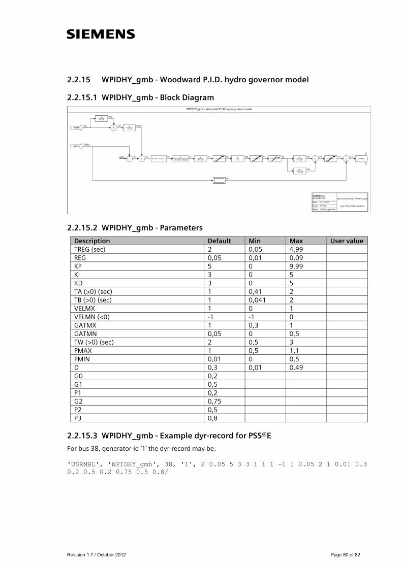
2.2.15 WPIDHY_gmb - Woodward P.I.D. hydro governor model
2.2.15.1 WPIDHY_gmb - Block Diagram
2.2.15.2 WPIDHY_gmb - Parameters
2.2.15.3 WPIDHY_gmb - Example dyr-record for PSS®E
For bus 38, generator-id ‘1’ the dyr-record may be: 'USRMBL', 'WPIDHY_gmb', 38, '1', 2 0.05 5 3 3 1 1 1 -1 1 0.05 2 1 0.01 0.3 0.2 0.5 0.2 0.75 0.5 0.8/
Description Default Min Max User value TREG (sec) 2 0,05 4,99 REG 0,05 0,01 0,09 KP 5 0 9,99 KI 3 0 5 KD 3 0 5 TA (>0) (sec) 1 0,41 2 TB (>0) (sec) 1 0,041 2 VELMX 1 0 1 VELMN (<0) -1 -1 0 GATMX 1 0,3 1 GATMN 0,05 0 0,5 TW (>0) (sec) 2 0,5 3 PMAX 1 0,5 1,1 PMIN 0,01 0 0,5 D 0,3 0,01 0,49 G0 0,2 G1 0,5 P1 0,2 G2 0,75 P2 0,5 P3 0,8
Revision 1.7 / October 2012 Page 81 of 82
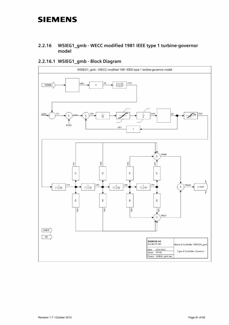
2.2.16 WSIEG1_gmb - WECC modified 1981 IEEE type 1 turbine-governor model
2.2.16.1 WSIEG1_gmb - Block Diagram

Revision 1.7 / October 2012 Page 82 of 82
2.2.16.2 WSIEG1_gmb - Parameters
2.2.16.3 WSIEG1_gmb - Example dyr-record for PSS®E
For bus 38, generator-id ‘1’ the dyr-record may be: USRMBL', 'WSIEG1_gmb', 38, '1', 0 0 10 2 2 0.1 0.3 -0.3 1 0.1 0.5 0.5 0 5 0.1 0.1 5 0.2 0.2 5 0.1 0.1 0.01 0.01 0.01 0.01 0.1 0.3 0.3 0.5 0.5 0.7 0.7 1 1 0/
Description Default Min Max User value JBUS 0 M 0 K 10 5 30 T1 (sec) 2 0 4,99 T2 (sec) 2 0 9,99 T3 (>0) (sec) 0,1 0,041 1 UO 0,3 0,01 0,3 UC (<0 ) -0,3 -0,3 -0,01 PMAX 1 0,5 2 PMIN 0,1 0 0,49 T4 (sec) 0,5 0,01 1 K1 0,5 -2 1 K2 0 0 0 T5 (sec) 5 0 9,99 K3 0,1 0 0,49 K4 0,1 0 0,49 T6 (sec) 5 0 9,99 K5 0,2 0 0,34 K6 0,2 0 0,54 T7 (sec) 5 0 9,99 K7 0,1 0 0,29 K8 0,1 0 0,29 db1 0,01 0 0,02 err 0,01 0 0,02 db2 0,01 0 0,02 GV1 0,01 PGV1 0,1 GV2 0,3 PGV2 0,3 GV3 0,5 PGV3 0,5 GV4 0,7 PGV4 0,7 GV5 1 PGV5 1 IBLOCK 0