Dynamic modelling and simulation for process design … · Dynamic modelling and simulation for...
6
Special Report 207 Chemical Weekly March 19, 2013 Dynamic modelling and simulation for process design and engineering ation, adherence to customer preferen- ces and commitments. Such third-party studies are seldom inexpensive and lead to higher project execution costs. To circumvent these challenges and improve project cycle time and costs, I n today’s oil and gas industry, companies are demanding more in terms of operational flexibi- lity, plant automation, reduced project cycle and optimisation. Besides other approaches, Process Dynamic Simula- tion is also being employed as a tech- nology-enabled solution to meet these challenges. Traditionally, process engineers often face the possibility of FEED and detailed engineering designs exceeding limits due to unforeseen circumstan- ces, for example, with complex control systems, operational philosophies and procedures. Potential problems during plant start-up, emergency shutdown and various turndown conditions may not be identified in advance due to insuf- ficient information on plant behaviour. Similarly, the effect of various process controllers on plant operations during transient events may not be completely understood. The selection and opera- tion of turbo machinery is another cri- tical area. Rotating equipment is often carefully scrutinised to avoid setbacks, such as compressor surges or start-up difficulties due to undersized drivers that result in depressurization, etc. Dy- namic simulation studies can success- fully address these problems. The use of such studies is now an established best practice to accurately assess these transient scenarios and develop reli- able and cost-effective solutions. While the business benefits of dy- namic modelling are widely accepted, many Engineering and Consulting (E&C) firms have not established in- house competency in this area. They typically rely on third-party service providers who often lack flexibility in terms of execution time, design evalu- leading E&C and consulting groups have developed their own process dynamic VIJAY J. SARATHY SUNIL PATIL R. VENKATESH BABU NAVEENKUMAR PANDIYAN About the Authors Vijay Sarathy’s expertise covers FEED/basic engi- neering, dynamic simulation and subsea/onshore pipeline flow assurance engineering for the oil and gas industry. Vijay currently works with Shell Projects & Technology, India as a Process Engineer at the Upstream Development Business Unit where he is responsible for Shell’s New Business Development activities in the Eastern Hemi- sphere. Prior to joining Shell, he has worked with major conglomerates of General Electric and ENI Saipem. Sunil Patil has more than 12 years of experience en- compassing an operating company, a consultancy in pro- cess design and simulation, and the development of en- gineering and operator training simulators (OTS). Sunil joined AspenTech in 2007 as a Consultant Engineer in As- penTech’s SIMOPT Services group before moving to his current Business Consulting role where he is responsible for business consulting and market development of Aspen- Tech’s engineering products and solutions for Asia Pacific. R.Venkatesh Babu is a Senior Process Engineer and has got experiences starting from conceptualisation to de- tail engineering for various oil & gas and petrochemical projects. Venkatesh is currently being with Saipem India Projects, India as a Process Engineer, where he is respon- sible for managing process engineering activities for vari- ous projects. Naveenkumar Pandiyan expertise covers FEED/de- tailed engineering, dynamic simulation and proposals / pre-bid activity for various projects in oil and gas indus- try. With more than 5 plus years of experience, he applies process simulation techniques to perform process design and analyses for gas booster & treatment plants and other studies. Naveenkumar currently works with Saipem India Projects Ltd. India as a Process Engineer. © This press clipping is under publisher copyright. It may be used as a Sales enablement tool with customers and for no other purpose.
Transcript of Dynamic modelling and simulation for process design … · Dynamic modelling and simulation for...

Special Report
207Chemical Weekly March 19, 2013
Dynamic modelling and simulation for process design and engineering
ation, adherence to customer preferen-ces and commitments. Such third-party studies are seldom inexpensive and lead to higher project execution costs.
To circumvent these challenges and improve project cycle time and costs,
I n today’s oil and gas industry, companies are demanding more in terms of operational flexibi-
lity, plant automation, reduced project cycle and optimisation. Besides other approaches, Process Dynamic Simula-tion is also being employed as a tech-nology-enabled solution to meet these challenges.
Traditionally, process engineers often face the possibility of FEED and detailed engineering designs exceeding limits due to unforeseen circumstan-ces, for example, with complex control systems, operational philosophies and procedures. Potential problems during plant start-up, emergency shutdown and various turndown conditions may not be identified in advance due to insuf-ficient information on plant behaviour. Similarly, the effect of various process controllers on plant operations during transient events may not be completely understood. The selection and opera-tion of turbo machinery is another cri-tical area. Rotating equipment is often carefully scrutinised to avoid setbacks, such as compressor surges or start-up difficulties due to undersized drivers that result in depressurization, etc. Dy-namic simulation studies can success-fully address these problems. The use of such studies is now an established best practice to accurately assess these transient scenarios and develop reli-able and cost-effective solutions.
While the business benefits of dy-namic modelling are widely accepted, many Engineering and Consulting (E&C) firms have not established in-house competency in this area. They typically rely on third-party service providers who often lack flexibility in terms of execution time, design evalu-
leading E&C and consulting groups have developed their own process dynamic
Vijay j. SarathySunil Patilr. VenkateSh BaBunaVeenkumar Pandiyan
About the Authors
Vijay Sarathy’s expertise covers FEED/basic engi-neering, dynamic simulation and subsea/onshore pipeline flow assurance engineering for the oil and gas industry. Vijay currently works with Shell Projects & Technology, India as a Process Engineer at the Upstream Development Business Unit where he is responsible for Shell’s New Business Development activities in the Eastern Hemi-sphere. Prior to joining Shell, he has worked with major conglomerates of General Electric and ENI Saipem.
Sunil Patil has more than 12 years of experience en-compassing an operating company, a consultancy in pro-cess design and simulation, and the development of en-gineering and operator training simulators (OTS). Sunil joined AspenTech in 2007 as a Consultant Engineer in As-penTech’s SIMOPT Services group before moving to his current Business Consulting role where he is responsible for business consulting and market development of Aspen-Tech’s engineering products and solutions for Asia Pacific.
R.Venkatesh Babu is a Senior Process Engineer and has got experiences starting from conceptualisation to de-tail engineering for various oil & gas and petrochemical projects. Venkatesh is currently being with Saipem India Projects, India as a Process Engineer, where he is respon-sible for managing process engineering activities for vari-ous projects.
Naveenkumar Pandiyan expertise covers FEED/de-tailed engineering, dynamic simulation and proposals / pre-bid activity for various projects in oil and gas indus-try. With more than 5 plus years of experience, he applies process simulation techniques to perform process design and analyses for gas booster & treatment plants and other studies. Naveenkumar currently works with Saipem India Projects Ltd. India as a Process Engineer.
© This press clipping is under publisher copyright. It may be used as a Sales enablement tool with customers and for no other purpose.
Special Report
Chemical Weekly March 19, 2013208
simulation capabilities and delivered so-lutions for their oil and gas clients. Bene-fits derived through these studies range from understanding plant process control schemes, improved flexibility through ope- rational changes, cost savings through flaring avoidance, power savings with faster compressor start-ups without de-pressurisation, surge mitigation schemes, and reduced project execution time. This initiative reduces dependence on expen-sive third-party engineering service pro-viders and fosters internal project execu-tion and competitive pricing.
This paper illustrates the business leverage through dynamic simulation using AspenTech’s ‘Aspen HYSYS Dy-namics’ as a technology enabler, and the benefits derived from helping pro-cess engineers gain greater insight while making more prudent engineering decisions in terms of improved design, reduced project cycle time and execu-tion costs. Process dynamic modelling and simulation is a paradigm shift in current engineering design practices. It adds a far-reaching and new dimen-sion to engineering perspective and enhanced customer value, although it cannot completely replace traditional methods entirely.
Process dynamic modellingProcess dynamic modelling in-
volves the use of fundamental and rigo-rous thermodynamics, heat and mass transfer, and fluid flow laws. The data required involves boundary conditions data, system volumes, valve characteris- tics, rotating equipment performance curves, type of controllers, etc. This al-lows process engineers to understand system behaviour, as well as capture the inertial effects or delays in the pro-cess times during process disturbances.
The commercial dynamic simu-lator ‘Aspen HYSYS Dynamics’ by AspenTech is used to perform dynamic simulation activities. Once built, the dynamic model is validated against steady-state data or field data to en-sure that the model will provide the correct and accurate plant operational response, performance and overall be-haviour when subjected to various dis-turbances.
The following sections discuss seve- ral actual dynamic simulation case studies from recent projects.
Case study 1: Eliminating over-sizing of pressure safety valves
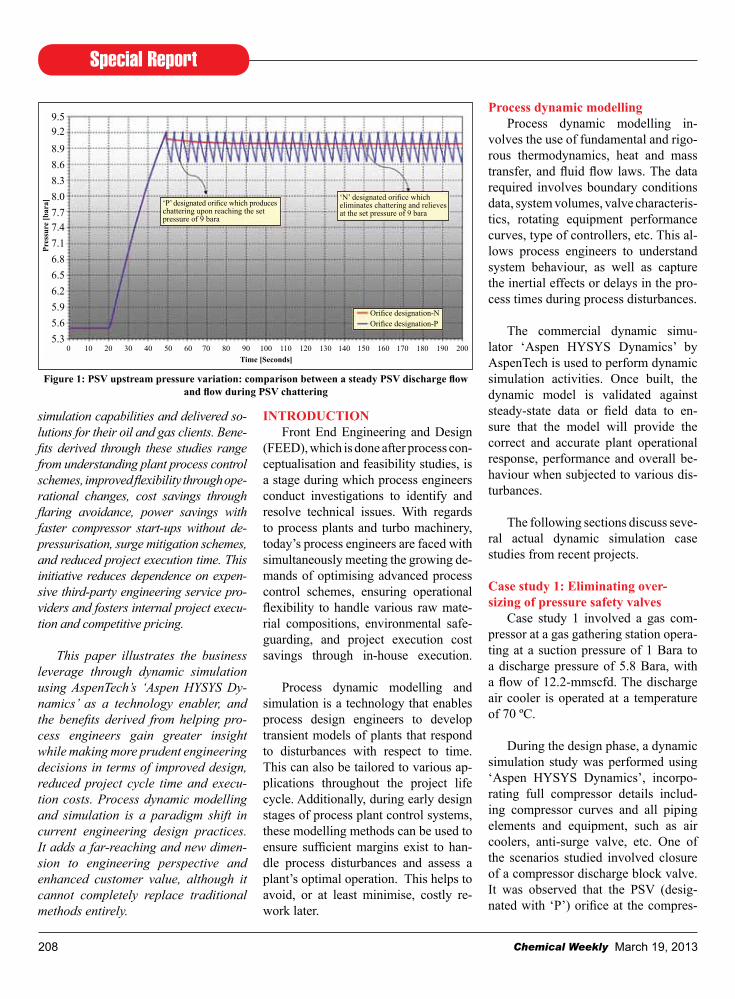
Case study 1 involved a gas com-pressor at a gas gathering station opera-ting at a suction pressure of 1 Bara to a discharge pressure of 5.8 Bara, with a flow of 12.2-mmscfd. The discharge air cooler is operated at a temperature of 70 ºC.
During the design phase, a dynamic simulation study was performed using ‘Aspen HYSYS Dynamics’, incorpo-rating full compressor details includ-ing compressor curves and all piping elements and equipment, such as air coolers, anti-surge valve, etc. One of the scenarios studied involved closure of a compressor discharge block valve. It was observed that the PSV (desig-nated with ‘P’) orifice at the compres-
IntroduCtIonFront End Engineering and Design
(FEED), which is done after process con-ceptualisation and feasibility studies, is a stage during which process engineers conduct investigations to identify and resolve technical issues. With regards to process plants and turbo machinery, today’s process engineers are faced with simultaneously meeting the growing de-mands of optimising advanced process control schemes, ensuring operational flexibility to handle various raw mate-rial compositions, environmental safe-guarding, and project execution cost savings through in-house execution.
Process dynamic modelling and simulation is a technology that enables process design engineers to develop transient models of plants that respond to disturbances with respect to time. This can also be tailored to various ap-plications throughout the project life cycle. Additionally, during early design stages of process plant control systems, these modelling methods can be used to ensure sufficient margins exist to han-dle process disturbances and assess a plant’s optimal operation. This helps to avoid, or at least minimise, costly re-work later.
Figure 1: PSV upstream pressure variation: comparison between a steady PSV discharge flow and flow during PSV chattering
‘P’ designated orifice which produces chattering upon reaching the set pressure of 9 bara
0 10 20 30 40 50 60 70 80 90 100 110 120 130 140 150 160 170 180 190 200time [Seconds]
‘N’ designated orifice which eliminates chattering and relieves at the set pressure of 9 bara
Orifice designation-NOrifice designation-P
Pres
sure
[bar
a]
9.59.28.98.68.38.07.77.47.16.86.56.25.95.65.3

Special Report
209Chemical Weekly March 19, 2013
sor discharge line was over sized for a flow of 12.2-mmscfd. As a result, valve chattering occurred with excess flaring. The study also revealed that the maxi-mum flow through the PSV was only 9.6-mmscfd, as opposed to the steady-state sized flow of 12.2-mmscfd. The problem was solved by replacing the ‘P’ orifice with an ‘N’ orifice designa-ted PSV that was smaller in size, which therefore significantly reduced the flar-ing flow by about 20% and eliminating the chattering effect.
Case study 2: Load sharing distribu-tion during residue gas compressor trip
Case study 2 involved a gas treat-ment plant which consisted of three parallel residue gas compressors that operated on sweet gas with a load shar-ing philosophy. The (3 × 33%) con-figuration consisted of a single master pressure controller and three slave con-trollers that operated the three compres-sor systems at nearly identical operat-ing points on the compressor curves.
The process conditions at each com-pression unit consisted of compressing 163-mmscfd of gas from a suction pres-sure of 31.1 Bara to a discharge pres-sure of 53 Bara at a compressor speed of 6,018-rpm. Each compressor’s duty was approximately 4.2-mw. Figure 2 shows a dynamic model of the com-pression system built in ‘Aspen HY-SYS Dynamics’ with a load sharing scheme.
The concern raised during the de-
Figure 2: Aspen HYSYS dynamics model of residue gas compressors

Special Report
Chemical Weekly March 19, 2013210
sign stage was whether, in the event of a single compressor failure, the remain-ing two compressors would be able to handle the total flow with no surging, when the two compressors are run at an expected higher speed. Upon perform-ing the operability study, it was proved successfully that the remaining two compressors could sustain the total flow by running at higher speeds of 6,636- rpm each, without tripping. Figure 3
shows the migration of the compressor operating point and indicates clearly that the surge line was never violated during a single compressor failure.
The simulation also exhibited that the load sharing scheme was robust enough to maintain a nearly identical parallel operation, with almost no dis-turbance or anti-surge valve opening. Moreover, it was proved that no flaring
of sweet gas in the residue gas compres-sion system had occurred. This demon-strates, unlike traditional methods that involve overall lumped parameter cal-culations or thumb rules (e.g., design-ing anti-surge system) where accuracy cannot be predicted during transient plant operation, that it can be overcome with dynamic simulation analyses. This provides a detailed insight into the plant operation, thereby helping to un-derstand the capabilities and limitations of the designed process plant.
Case study 3: demethanizer column recovery profiles during turbo expander trip
Case study 3 consisted of two paral-lel natural gas liquid (NGL) units in operation that work on an ethane reco-very process wherein a turbo expander is used to recover a mixture of methane and ethane. Figure 4 is a block flow dia-gram of this process. The turbo expan-der is controlled by a master pressure controller that senses the throughput at the slug catcher unit which receives the wellhead fluids and alters the turbo ex-pander operating point in the NGL unit. The master pressure control also limits the maximum amount of well fluids through the gas sweetening absorber
Figure 4: Block flow diagram of NGL recovery unit in the overall gas plant
Slug catcherunit
Master pressure controller to control NGL unit turbo expander operating point (Alternative 1)
Gas cooling & Amine treatment
Train 1
Gas cooling & Amine treatment
Train 2
Gas dehydration
Train 1
Gas dehydration
Train 2
Gas compression &
Export
NGL recovery unit - Train 1
NGL recovery unit - Train 2
Master pressure controller shifted to NGL recovery unit to control NGL unit turbo expander operating point (Alternative 2)
Figure 3: operating point migration of Compressor A and B after trip of Compressor C
7327 rmp (105% Speed)6978 rmp (100% Speed)6280 rmp (90% Speed)5582 rmp (80% Speed)4885 rmp (70% Speed)Surge Limit line (SLL)Operating point migrationOperating point migration
Final operating point
150
135
120
105
90
75
60
45
30
15
00 1500 3000 4500 6000 7500 9000 10500 12000 13500 15000
Poly
trop
ic h
ead
[kj/k
g]
Actual volumetric flow [Act_m3/h]
Special Report
211Chemical Weekly March 19, 2013
section by limiting the turbo expander range of operation. The NGL unit con-sists of a demethanizer and the column recovers during the normal ethane reco-very process at 99.4% C1 and 0.23% C2.
During the event of a turbo ex-pander trip, the NGL unit would switch to Joule-Thompson (J-T) mode of operation in which all the dehydrated gas from the dry gas chillers would be diverted through the J-T valve. The de-methanizer column recoveries in this mode of operation would be 96.1%
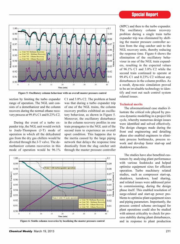
C1 and 3.8% C2. The problem at hand was that during a turbo expander trip of one of the NGL trains, the column recovery profiles exhibited an oscilla-tory behaviour, as shown in Figure 5. Moreover, the oscillatory disturbance in the column recovery profiles in one train propagates to the NGL unit of the second train to experience an overall upset condition. This happens due to the inertia caused by the large piping network that delays the response time drastically from the slug catcher unit through the master pressure controller
(MPC) and then to the turbo expander. The oscillatory column recovery problem during a single train turbo expander trip was eliminated by shift-ing the master pressure controller ac-tion from the slug catcher unit to the NGL recovery units, thereby reducing the response time. Figure 6 shows the elimination of the oscillatory beha-viour in one of the NGL train expand-ers, resulting in the expected values of 96.1% C1 and 3.8% C2 while the second train continued to operate at 99.4% C1 and 0.23% C2 without any disturbances in the column profiles. As a result, dyna-mic simulation proved to be an invaluable technology to iden-tify and root out such control system related issues.
technical merits
The aforementioned case studies il-lustrate the critical role played by pro-cess dynamic modelling in a project life cycle, whereby numerous design issues were identified and solved effectively. The design changes made during the front end engineering and detailing phase also enabled engineers to elimi-nate process bottlenecks, process re-work and develop faster start-up and shutdown procedures.
The studies have also benefited cus-tomers by analysing plant performance with various feedstocks and helped optimise equipment sizes for efficient operation. Turbo machinery related studies, such as compressor start-up, shutdown, turndown, load sharing, and related issues were addressed prior to commissioning, during the design phase itself. This enabled resolution of surge-related and start-up power pro-blems to optimise plant equipment sizes and piping parameters. Importantly, the process control scheme envisaged for plant operations could also be studied with utmost criticality to check for pro-cess stability during plant disturbances, and in response to plant production
Figure 5: oscillatory column behaviour with an overall master pressure control
1.00
0.99
0.98
0.97
0.96
0.95
0.94
0.93
0.92
0.91
0.90
0.1
0.09
0.08
0.07
0.06
0.05
0.04
0.03
0.02
0.01
0
Met
hane
rec
over
y Fr
actio
n [-
]
Eth
ane
rec
over
y Fr
actio
n [-
]
Unit 741 Methane RecoveryUnit 742 - Methane RecoveryUnit 741 - Ethane RecoveryUnit 742 - Ethane Recovery
0 5 10 15 20 25 30 35 40time [min]
Figure 6: Stable column recoveries by localizing the master pressure control
1.00
0.99
0.98
0.97
0.96
0.95
0.94
0.93
0.92
0.91
0.90
0.1
0.09
0.08
0.07
0.06
0.05
0.04
0.03
0.02
0.01
0
Met
hane
rec
over
y Fr
actio
n [-
]
Eth
ane
rec
over
y Fr
actio
n [-
]
Unit 741 Methane RecoveryUnit 742 - Methane RecoveryUnit 741 - Ethane RecoveryUnit 742 - Ethane Recovery
train 1 with turboexpander operation
Train 2 with J-T mode operation
0 5 10 15 20 25 30 35 40time [min]

Special Report
Chemical Weekly March 19, 2013212
throughput and compositional changes. Projects that require environmental considerations to be respected in an emergency event, such as inadvertent flaring, can be attended to effectively by estimating the amount of flaring. In situations where flaring would be inevi-table, flaring of sweet gas in preference to sour gas could be effected with an operational change. Process dynamic modelling and simulation is a valuable tool to recognise these opportunities and to make appropriate, cost-effective and reliable changes. This technology has dramatically advanced in accuracy and ease-of-use in recent years, and has im-proved engineering decision making as well as building customer confidence.
Commercial benefitsDynamic simulation studies are
sometimes subcontracted to third party engineering service providers/vendors by engineering contractors. This prac-tice is quite expensive as the work is gauged by the complexity of the analy-ses, and in some cases due to competi-tive disadvantage from a lack of tech-nical and commercial resources within engineering contractors. In addition, customer expectations are becoming more demanding and there is need to felt for a greater perspective on plant performance for various operating sce-narios. With third party subcontracting there is risk of exceeding projected bud-get costs in cases of increased case stu- dies and re-work due to project docu-ment revisions. Another aspect that im-plies a cost increase for such studies is dynamic model customisation. This in-volves additional custom thermodyna-mic modelling, including sensitivity stu- dies between thermodynamic packages often required to match project specific requirements. This represents an addi-tional increase in project costs.
Costs associated with engineering contractors can vary from US$20 to 50 per man-hour in India – based on the
authors’ experience, while third party subcontractors typically charge be-tween US$ 80 to 120 per man-hour de-pending on the complexity of the study and schedule. Considering an average cost of US$40 per man-hour as a base price offered by engineering vendors against an average cost of US$100 per man-hour by third party subcontractors, the man-hour price variation is more than 150% (i.e., US$60 more per man-hour) with respect to base price.
A typical study performed by most engineering contractors is a compressor dynamic simulation for surge analy-sis of gathering centre compressors. Prices quoted by a third party vendor for various operating scenarios can be higher by nearly 90% (~US$380,000) for an execution period of eight months when compared to a typical engineer-ing contractor’s quoted price. This in-stance clearly indicates the expensive nature of third party services. The end customer may require the study to be made for the as-built plant, i.e., until pre-commissioning. This means when using a third party vendor, project costs could rise significantly as scenarios are reworked as the project progresses. On the other hand, the same project exe-cuted internally by engineering con-tractors using dynamic simulation tech-niques would be highly cost effective and provide flexibility in responding to customer preferences.
A similar situation can be expected during the engineering phase for a fer-tiliser project where a dynamic simu-lation study needs to be performed to check for the PSV response during vari-ous process upset scenarios. Studies usually include analysis of plant safe-guarding philosophy where the set pres-sures of the PSVs also have to be analy-sed. The price quoted by a third party vendor can be expected to be higher by nearly 33% (~US$45,000) for an execu-tion period of six months. Such exam-
ples point to the expensive commercial nature of dynamic simulation services.
From the comparisons made, it can be inferred that there are significant cost implications for dynamic simula-tion studies when offered by third party vendors. This affects the engineering contractor’s profit margins during pro-ject execution. To reduce dependency and to avoid such high price services, internal execution of dynamic simula-tion studies by engineering contractors can be implemented easily using avail-able and proven tools such as ‘Aspen HYSYS Dynamics’.
ConCLuSIonSThe case studies presented in this
paper demonstrate the critical role played by process dynamic simulation in a project life cycle. Although such advancements in engineering design practices cannot completely replace traditional methods of engineering, it represents a paradigm shift in the current design methods and practices which provides a new dimension to en-gineering design and analyses.
This paper also highlights how in-novative process dynamic modelling and simulation techniques can be lever-aged by engineering contractors to add value to clients, achieve significant time and cost savings, and avoid use of third party engineering service providers and thereby improve competitiveness.
rEFErEnCESRobert H. Perry, Don W. Green,
Perry’s Chemical Engineers’ Hand-book, Seventh Ed., 1997.
Aspen HYSYS Process User Manual.
AspenTech Support Site and its Knowledge Base at:
http://support.aspentech.com trademarks: Aspen HYSYS is a
registered trademark of Aspen Techno-logy Inc.