Dynamic Load Balancing and Channel Allocation in Indoor ...rakl/Moe_proposal.pdf · The 802.11...
21
1 Dynamic Load Balancing and Channel Allocation in Indoor Wireless Local Area Networks A Thesis Proposal Presented By Mohamad Haidar MS. Roosevelt University, Chicago, IL. 2002 BS. Lebanese American University, Beirut, Lebanon. 2000 To The Department of Applied Science in partial fulfillment of the requirements for the degree of Doctor of Philosophy University of Arkansas at Little Rock Little Rock, Arkansas November 2005 The research proposal of Mohamad A. Haidar is approved:
Transcript of Dynamic Load Balancing and Channel Allocation in Indoor ...rakl/Moe_proposal.pdf · The 802.11...

1
Dynamic Load Balancing and Channel Allocation in
Indoor Wireless Local Area Networks
A Thesis Proposal Presented
By
Mohamad Haidar
MS. Roosevelt University, Chicago, IL. 2002
BS. Lebanese American University, Beirut, Lebanon. 2000
To
The Department of Applied Science
in partial fulfillment of the requirements for the degree of
Doctor of Philosophy
University of Arkansas at Little Rock
Little Rock, Arkansas
November 2005
The research proposal of Mohamad A. Haidar is approved:

2
Hussain M. Al-Rizzo, Chair Date
Robert Akl, Date
Seshadri X. Mohan Date
Yupo Chan Date
Hayder Al-Shukri Date
Hassan El-Salloukh Date
University of Arkansas at Little Rock
Little Rock, Arkansas

3
1. Introduction
Wireless communications is one of the most active areas of technology development of
our time. Over the recent years it has rapidly emerged in the market providing users with
network mobility, scalability and connectivity. Wireless Local Area Networks (WLANs)
have been developed to provide users in a limited geographical area with high bandwidth
and similar services supported by the wired Local Area Network (LAN) [1].
The IEEE (Institute of Electrical and Electronics Engineers) 802.11 standards
offer performance nearly comparable to that of Ethernet. In addition, they provide
scalability, mobility, flexibility and relative ease of integration of wireless access. Unlike
wired networks, WLANs, which uses IEEE 802.11 standards, transmit and receive radio
waves through the air medium between a wireless client and an Access Point (AP), as
well as among two or more wireless clients within a certain range of each other [2].
Radio wave signals propagate through walls, ceilings, and even cement structures.
A WLAN is a flexible data communications system that can either replace or
extend a wired LAN where cost is an issue or running cables between floors or different
rooms on the same floor is not feasible [3]. Examples of structures that are difficult to
wire are warehouses, historic buildings, and manufacturing facilities. A WLAN basically
consists of one or more wireless devices connected to each others in a peer-to-peer
manner or through APs, which in turn are connected to the backbone network providing
wireless connectivity to the covered area. Fig.1 shows a typical layout of a WLAN with
two APs [4].

4
Fig. 1: WLAN with two APs
A WLAN can be configured in two basic modes:
• Peer-to-peer (ad hoc mode)- This mode consists of two or more PCs equipped
with wireless adapter cards, but with no connection to a wired network, as shown
in Figure 2 [5]. It is usually used to quickly and easily set up a WLAN where no
infrastructure is available, such as a convention center or offsite meeting location.
• Client/Server (infrastructure networking)- This mode consists of multiple stations
(Laptops, PDAs, PCs) linked to a central hub that acts as a bridge to the resources
of the wired network, as shown in Figure 3 [6], offering fully distributed data
connectivity
Fig. 2: Peer-to-Peer Wireless Configuration

5
Fig. 3: Client/Server Wireless Configuration
In many situations, the deployment of a single AP is not enough to provide the
required connectivity. As an example, large facilities, such as an office complex, a
university campus, hospitals, large buildings or warehouses generally require many
cooperating APs in order to provide the required services to the end users.
Services in the WLAN environment should be designed in order to achieve
maximum coverage and throughput. AP placement, channel assignment and load
balancing should be carefully examined to maximize coverage and throughput.
Optimizing APs’ placements and channel allocations result in improvement in Signal-to-
Interference ratio (S/I), better bandwidth utilization for the whole network and higher
throughput [7].
A major challenge when deploying WLANs is the channel allocation problem.
The 802.11 wireless LANs operate in the unlicensed Industrial, Scientific and Medical
(ISM) frequency of 2.4 GHz. This introduces interference from other electronic devices,
such as microwave ovens and wireless phones. There are two types of interference in
WLANs: adjacent channel interference and co-channel interference. Adjacent channel
interference takes place between adjacent APs due to the fact that APs may share the
same frequency bandwidth. On the other hand, co-channel interference takes place
between APs using the same frequency channels [8].
6
The 802.11 standard specifies three techniques for data transmission in the
physical (PHY) layer for lower data rates: Infrared (IR), frequency hopping spread
spectrum (FHSS) and direct sequence spread spectrum (DSSS) [9]. Infrared technology,
which is seldom used in WLANs, uses diffused (or reflected) transmission that does
require line-of-sight and is limited to small areas due to the fact that IR, like light cannot
penetrate opaque objects. However, most 802.11 systems of lower data rates use spread-
spectrum technology. There are two spread spectrum techniques used in 802.11 that use
short range radio waves operating in the unlicensed ISM band at 2.4 GHz: DSSS and
FHSS. DSSS generates a chipping code (redundant bit pattern) for each bit to be
transmitted. Due to this redundancy in transmission if one or more bits are damaged, the
receiver can still recover the original data without the need for retransmission. To the
unintended receiver, DSSS appears as low-power noise and is rejected. Of course, the
drawback of this technique is the need for more bandwidth which is a limited resource in
IEEE 802.11. On the other hand, FHSS uses a narrowband carrier (1 MHz), with 79
channels which begins at 2.412 GHz in the U.S. [7], which changes frequency in a
pattern known to both transmitter and receiver. This technique provides good security
since a user who does not know the hopping sequence of channels, cannot eavesdrop.
FHSS appears as a short duration impulse noise to the unintended receiver. The main
disadvantage of DSSS and FHSS is the low data rate (1 Mbps or 2 Mbps).
Two new techniques were introduced in 1999 for higher data rates [10, 11]. The
two techniques are: Orthogonal Frequency Division Multiplexing (OFDM) and high
range direct sequence spread spectrum (HR-DSSS). OFDM splits the data over multiple
narrowband carriers (frequencies) to transmit simultaneously. The advantage of OFDM is

7
the efficient use of the spectrum, better immunity to narrow band interference and lower
multi-path distortion [12]. OFDM is used by 802.11a in the 5 GHz band and 802.11g in
the 2.4 GHz. On the other hand, HR-DSSS spread spectrum, which is used by 802.11b, is
the same as DSSS spread spectrum but uses 11 x 106 chips per second to achieve 11
Mbps data rate in the 2.4 GHz ISM band. However, HR-DSSS does support and is
compatible with lower data rates of 1, 2, 5.5 and 11 Mbps.
2. Problem Statement and Scope of Thesis
This section summarizes the research the author plans to perform in order to complete the
dissertation. Details of the techniques as well as plan of action are detailed later in this
proposal.
Statement of Intent The author plans to optimize AP selection by dynamically balancing
traffic load and minimizing channel interferences by assigning optimal channels to the
access points of an indoor WLAN.
In wireless communications, there is always a demand for more bandwidth,
increased coverage or range, increased data rate, decreased interference, and lower costs.
Today, most AP based WLANs are inefficient in the sense they associate with new
comers on the basis of power instead of user density. Therefore, they end up providing
far less total throughput than they should [13].
Designing 802.11 WLANs include two major components: placement of APs in
the service areas and assignment of radio frequencies to each AP. Coverage and capacity
are some key issues when placing APs in a service area. APs need to cover all users.
According to [7], “a user is considered to be covered if power received from its
8
corresponding AP is greater than a given threshold.” Moreover, from a capacity point of
view, APs need to provide certain minimum data rate to users located in the coverage
area.
The first challenge resides in selecting APs positions in an optimal way to achieve
maximum coverage and throughput. In other words, APs should be placed to achieve
maximum coverage possible with the least number of APs.
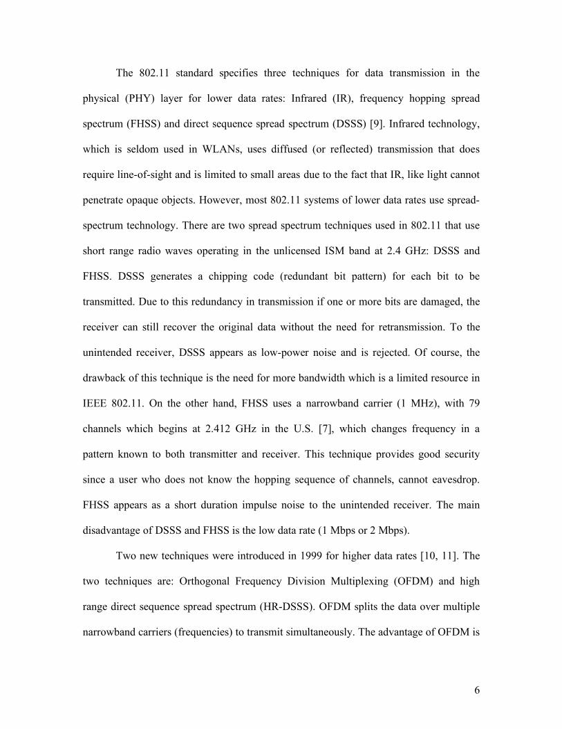
According to [14], the number of APs needed to support the load of a given
coverage area is determined using the following equation
NAP = (bwuser * Nuser * %activity) / (%effeciency*rateassociation) (1)
where NAP is the number of APs needed to provide the required capacity, bwuser is the
bandwidth required per user, Nuser is the number of users in the area, %activity is the
fraction of time the users are active, %efficiency is the channel efficiency defined as the
ratio of actual-rate over association-rate which is rateassociation. Equation (1) is used for
large coverage areas that require high bandwidth with uniformly distributed users. If a
small amount of bandwidth is needed for a large coverage area, then the number of APs
cane be determined by the following equation [14],
NAP = Ctotal / CAP, (2)
where Ctotal is the total area to be covered, and CAP is the coverage area of a single AP
based on maximum power.
The second challenge is to assign channels to the APs in a manner that achieves
minimum co-channel and adjacent cell interferences.
The last and greatest challenge of all is to dynamically keep the network at
optimum performance. In other words, every node that connects to or disconnects from
9
an AP should be updated into the WLAN network database through a centralized station.
The WLAN network in turn reconfigures the association and dissociation of nodes with
their respective APs in order to maintain the best level of performance i.e. maximum
coverage and minimum interference. Node mobility can be looked at as dynamic traffic
decreasing with the dissociation and increasing with the association of nodes. Few
techniques have been proposed to cover the first two challenges for fixed or static load [7,
8], where the distribution of demand clusters and service areas are known before hand.
The author plans to add the dynamic feature in conjunction with optimal AP
placement and channel assignment to improve the overall network performance and
throughput through minimizing cost, in terms of number of APs, and maximizing
bandwidth utilization.
3. Literature Review
There are various similarities between WLANs and cellular networks. Several
deployment problems have been extensively studied in the context of cellular networks
[14]. The problem of optimizing the selection of APs can be traced back to the cellular
communication industry where the authors in [15, 16] stated that “one of the most
important problems in the design phase of a cellular radio network is where to locate and
how to configure base stations.” The objective was to serve the most traffic while the
amount of interference is kept small. In [15] the authors provided analytical optimization
problems where each problem was formalized as an Integer Linear Program (ILP) and
was solved for relevant examples of realistic problem size. However, in [16] the authors
used a different optimization algorithm called Divide-and-Conquer to select the BSs. The

10
algorithm divides the total serviced area into equal sized grids and then the problem is
solved in each of these grids by exhaustive search. The authors in [17] developed an
analytical framework for the analysis of dynamic load balancing schemes with multiple
traffic types (voice and video). Moreover, theoretical expressions were developed to
study the call blocking probability performance of voice and video traffic cellular
networks which employ dynamic load balancing schemes. Results showed that with
proper amount of load balancing capability (load balancing channels) and proper amount
of relay station coverage, the call blocking probability for all traffic types can be reduced
significantly up to 60% in hot (congested) cells.
In [7] and [8], the authors proposed an approach to optimize AP placement and
channel assignment in WLANs by formulating an optimal ILP. The optimization
objective in [7, 8] is to minimize the maximum channel utilization on a data network,
which quantitatively represents congestion at the hot spot in WLAN service areas. By
using a simple model of demand point to construct various amounts of traffic by users
and channel assignment graphs, the WLAN service design process can be easily
performed. The proposed method finds the best set of AP locations for load balancing by
considering user traffic demands (constant bandwidth is provided by a channel at an AP
regardless of the number of active users and connection bit rates). From simulation
results, it is shown that the maximum channel utilization or the number of selected APs is
minimized. The authors in [8] considered dynamic load balancing traffic but did not
provide the reconfiguration of demand clusters in the network. Traffic disruption, caused
by the association and dissociation of demand clusters to and from their respective APs,
is minimized

11
In [18], the authors reported experimental and analytical results to address the
problem of designing high capacity WLANs based on 802.11b technology. The authors
studied the impact of hidden and exposed terminal on the capacity increase in a layout of
APs in a WLAN. The hidden terminal problem occurs when two or more stations outside
the “hearing” range of each other transmit to one station that is within the hearing range
of both, causing a collision. Figure 4 shows the hidden terminal problem [19].
Fig. 4: Hidden terminal phenomenon
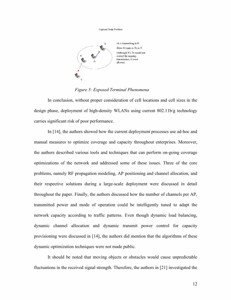
The exposed terminal phenomenon, shown in Figure 5 [20], occurs when station A is
transmitting to Station B and station X wants to transmit to station Y but cannot do so
since it is in the hearing range of station A, so it must defer its own transmission.
However, if both stations A and X transmit at the same time, all frames would be
successfully received. Hence, the large transmission range of station A has prevented
other stations from sending and receiving, while they can do so without colliding.
Therefore, in the design of high density WLANs, particular attention must be paid to the
means by which the effects of exposed terminals in the network can be reduced since
there is limited control over transmission ranges of wireless devices.
12
Figure 5: Exposed Terminal Phenomena
In conclusion, without proper consideration of cell locations and cell sizes in the
design phase, deployment of high-density WLANs using current 802.11b/g technology
carries significant risk of poor performance.
In [14], the authors showed how the current deployment processes use ad-hoc and
manual measures to optimize coverage and capacity throughout enterprises. Moreover,
the authors described various tools and techniques that can perform on-going coverage
optimizations of the network and addressed some of these issues. Three of the core
problems, namely RF propagation modeling, AP positioning and channel allocation, and
their respective solutions during a large-scale deployment were discussed in detail
throughout the paper. Finally, the authors discussed how the number of channels per AP,
transmitted power and mode of operation could be intelligently tuned to adapt the
network capacity according to traffic patterns. Even though dynamic load balancing,
dynamic channel allocation and dynamic transmit power control for capacity
provisioning were discussed in [14], the authors did mention that the algorithms of these
dynamic optimization techniques were not made public.
It should be noted that moving objects or obstacles would cause unpredictable
fluctuations in the received signal strength. Therefore, the authors in [21] investigated the

13
influence of moving obstacles, such as people, on indoor radio wave propagation and the
effect on received signal quality in WLAN. It was shown that the presence of moving
obstacles seriously affects the performance of the system by introducing large variations
in the received signal strength due to fast fading and small area shadowing. The authors
proposed a model for WLAN channel parameter prediction incorporating the effects of
moving objects on performance of an IEEE 802.11 WLAN.
4. Goals and Objectives
The proposed research is based on needs that have been identified based on a
comprehensive review of the current state of the art knowledge in the field of deploying
APs and dynamic traffic load balancing in WLANs. The goals of this research can be
summarized as follows:
1. Optimal AP selection and traffic allocation: Formulate an optimal access point
placement by balancing present traffic load.
2. Optimal dynamic channel allocation: Formulate a dynamic optimal channel
assignment by minimizing interference between APs in WLANs.
3. Dynamic reconfiguration of AP assignments: Formulate a dynamic optimal
reconfiguration assignment of newly associating/dissociating nodes by keeping
channel interference between APs at a minimum.
The simulation of the various components of the research will be done using a variety of
computer packages including, but not limited to, LINear and General Optimization
(LINGO) [22], Wireless InSite [23], and OPtimized Network Engineering Tools
(OPNET) [24]. In addition to these tools, programming using C++ and Matlab will be
14
utilized. The emphasis of the simulations will focus on evaluating the performance of the
system:
• Under a variety of signal-to-interference ratios,
• On a varying traffic load with time,
• With various propagation models, and
• With realistic models of buildings and floors.
5. Originality and Relation to Other Work
Little work has been done on the optimization of AP placements and channel allocations.
Previous research considered static optimization where the number of demand clusters
was fixed and assumed not to change with time.
The work reported by [7] and [8] dealt with load balancing techniques performed
only at association time. In other words, the models presented so far are not realistic, for
they do not support time varying loads. A dynamic load balancing scheme should be able
to:
• Continuously balance the traffic load on APs,
• Dynamically allocate non-overlapping channels to newly associated clients and,
• Allocate non-occupied non-overlapping channels from newly dissociating clients
to congested hot spots on the network.
For instance, if a client joins the network, the scheme will associate the client with
the least loaded access point or channel available in the neighborhood. However, the
traffic patterns of clients can change over time making the associated channel non-
optimal. Therefore, a dynamic load-balancing scheme is proposed in this research,

15
whereby newly joining clients are re-associated with a less loaded channel on the AP and
newly not used channels are assigned to congested APs to optimize the load traffic and
channel allocation on the network for coverage and capacity provisioning satisfying the
co-channel and adjacent channel interference constraints.
6. Research Implementation Plan
The research is planned to be executed in three phases. Phase one, or the preparatory
phase, has already been started and is in progress. Phase two and three will be executed
independently except for some tasks that could be done concurrently.
6.1 Phase One
The work described in this subsection has been started and is in progress. This phase
includes literature review and getting familiar with the available software packages-
OPNET [24] and Wireless InSite [23]. Some simulations have been already conducted
using these two software packages. For instance, in Wireless InSite, an outdoor
simulation tutorial of propagation paths and models have been conducted in the city of
Rosslyn, VA. Figure 6 shows the top view of Rosslyn, VA. Although this simulation is
not directly related to the indoor environment, it does help achieve the basic
understanding of the software features and its capabilities that will assist in simulating
future indoor models. The software is capable of displaying propagation results, visual
paths traced between receiver and transmitter, signal degradations and strengths with
distance taking into consideration moving objects and materials of objects of interest.
Another tutorial based on an indoor environment was simulated using the design
proposed in [25] taking into consideration the material of the walls, doors, windows,
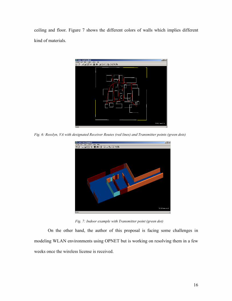
16
ceiling and floor. Figure 7 shows the different colors of walls which implies different
kind of materials.
Fig. 6: Rosslyn, VA with designated Receiver Routes (red lines) and Transmitter points (green dots)
Fig. 7: Indoor example with Transmitter point (green dot)
On the other hand, the author of this proposal is facing some challenges in
modeling WLAN environments using OPNET but is working on resolving them in a few
weeks once the wireless license is received.
17
At the end of this phase, the author would have developed sufficient amount of
simulations on realistic indoor environments that should aid in formulating the
optimization problem with the properly defined constraints. This phase will provide
realistic modeling scenarios for the indoor environments.
6.2 Phase Two
Phase two involves formulating the optimization problem. This phase runs concurrently
with phase one where the author is attending a graduate course on optimization offered
by Dr. Yupo Chan in order to help in formulating the ILP algorithm. At the end of this
phase, a static optimization formulation should be available to provide results for the
initial configuration of APs placements and assignment of non-overlapping channels to
present demand clusters. The results will be validated by comparison with other
configurations published in the literature.
6.3 Phase Three
In the final phase, the dynamic feature will be added to the optimization techniques that
will allow continuous reconfiguration of the network with time as clients join or leave the
network based on the traffic load on APs and other constraints, such as S/I and power
control. A mobility model based on Poisson distribution will be simulated to represent the
dynamic feature. This will be presented in terms of a statistical distribution that will
provide realistic mobility of the traffic. Several simulations will be carried out under
different scenarios and constraints such as, different propagation models, different
configuration of nodes and various signal-to-noise ratio threshold values. Also, results
will be presented and compared to the models reported in [7] and [8].
18
7. Expected Outcome
In this research a study of new concepts will be developed to efficiently utilize the
channel and improve the capacity and coverage area in a WLAN. At the end of this
research, formulation and results achieved will be presented. The applicability of the
model presented in the research will be tested and compared to realistic models. It is
expected that the proposed dynamic traffic load-balancing scheme will lead in utilizing
the channel (capacity) and coverage more efficiently.
8. Conclusion
The demand for more capacity and better coverage in a WLAN environment has been
increasing steadily for the last few years [26]. However, the assigned channels in the
IEEE 802.11 WLAN are fixed (14 frequency channels, 1 through 11 are used in USA).
Researchers have been actively investigating how to efficiently utilize the available
channels by implementing different techniques and algorithms such as, better placement
algorithms for APs, load-balancing on APs, and assigning non-overlapping channels
(frequencies) to adjacent APs to minimize interference. Dynamic load balancing is a
technique that improves coverage areas of APs and capacity provisioning in a WLAN
environment. Unlike other load balancing techniques, the proposed approach strives to
give the optimal performance as time progresses.
19
REFERENCES
1. B. Crow, I. Widjaja, J. Kim, and P. Sakai, ”IEEE 802.11 Wireless Local Area
Networks,” IEEE Communications Magazine, pp. 116-126, Sept. 1997.
2. J. Reynolds. Going Wi-Fi: A Practical Guide to Planning and Building an 802.11
Network. CMP Books, 2003.
3. Intel Staff. (2001). IEEE 802.11b High Rate Wireless Local Area Networks. Intel.
Retrieved July 15, 2005 from the World Wide Web:
http://www.utdallas.edu/ir/wlans/whitepapers/wireless_lan_Intel.pdf.
4. http://www.net4india.com/images/wlan-inframode.gif
5. http://www.inet.mw/images/adhoc_wlan.gif
6. http://www.malima.com.br/wifi/wifiClientServer.jpg
7. R. Akl and S. Park. “Optimal Access Point selection and Traffic Allocation in
IEEE 802.11 Networks,” Proceedings of 9th World Multiconference on Systemics,
Cybernetics and Informatics (WMSCI 2005): Communication and Network
Systems, Technologies and Applications, paper no. S464ID, July 2005
8. Y. Lee, K. Kim, and Y. Choi. Optimization of AP placement and channel
assignment in wireless LANs. LCN 2002. 27th Annual IEEE Conference on Local
Computer Networks, pages 831-836, November 2002.
9. William Stallings. Wireless Communications and Networks. Prentice Hall, 2002.
10. IEEE. Wireless LAN medium access control (MAC) and physical layer (PHY)
specifications – Amendment 1: high-speed physical layer in the 5 GHz band.
IEEE standard 802.11a, 1999.

20
11. IEEE. Wireless LAN medium access control (MAC) and physical layer (PHY)
specifications – Amendment 1: high-speed physical layer in the 5 GHz band.
IEEE standard 802.11b, 1999.
12. http://www.wave-report.com/tutorials/OFDM.htm
13. G. Tan and J. Guttag. “Capacity Allocation in Wireless LANs.” MIT LCS
Technical Report, MIT-LCS-TR-973, Cambridge, MA, Nov. 2004.
14. A. Raniwala and T. Chiueh, “Deployment Issues in Enterprise Wireless LANs”.
RPE report, September 2003.
15. R. Mathar and T. Niessen. “Optimum positioning of base stations for cellular
radio networks.” Wireless Networks, pages 421-428, 2000.
16. C. Glaber, S. Reith, and H. Vollmer. “The Complexity of Base Station positioning
in Cellular Networks.” Workshop on Approximation and Randomized Algorithm
in Communications Networks, March 2000.
17. E. Yammaz and O. K. Tonguz. “Dynamic Load Balancing Performance in
Cellular Networks with Multiple Traffic Types.” IEEE Vehicular Technology
Conference, pages 3491-3495, September 2004
18. S. Gordon and A. Dadej. “Design of High Capacity Wireless LANs based on
802.11b Technology.” 6th International Symposium on Communications
Interworking, pages 133-144, October 13-16, 2002.
19. http://www.iitk.ac.in/mladgp/rgandhi%20website/80211b/hidden_node_problem.j
pg
20. http://www.iitk.ac.in/mladgp/rgandhi%20website/80211b/exposed_node_problem
1.jpg
21
21. M. Klepal, R. Mathur, A. McGibney, and D. Pesch. “Influence of People
Shadowing on Optimal Deployment of WLAN Access Points.” IEEE Vehicular
Technology Conference, pages 4516-4520, 2004.
22. Lindo Systems Inc. LINGO. http://www.lindo.com
23. Remcom Products Inc. Wireless InSite. http://www.remcom.com/WirelessInSite/
24. OPNET technologies Inc. OPNET. http://www.opnet.com
25. C. Yang, B. Wu, C. Ko, “A Ray-Tracing Method for Modeling Indoor Wave
Propagation and Penetration”, IEEE Trans. On Antennas and Propagation, Vol.
46, No. 6, pp. 907-919, June 1998.
26. http://196.34.2.208/PARADIGMA/ESDA_SCRIPTS/News.ASP?pklNewsID=77
37&pklIssueID=276