Dynamic Force and Strain Sensors - PCB Piezotronics, Inc
202
Dynamic Force and Strain Sensors 1.1 PCB Piezotronics, Inc. Toll-Free in USA 888-684-0004 716-684-0001 www.pcb.com Quartz, piezoelectric force sensors are durable measurement devices which possess exceptional characteristics for the measurement of dynamic force events. Typical measurements include dynamic and quasi-static forces as encountered during actuation, compression, impact, impulse, reaction, and tension. Applications for quartz force sensors include balancing, crash testing, crimping, crushing, cutting, drop testing, fatigue testing, forming, fracture testing, machinery testing, materials testing, penetration testing, press monitoring, punching, stamping, tensile testing, and vibration testing. Since the measurement signal generated by a quartz force sensor will decay over time, long-term, static force measurements are not practical. Short-term, or “quasi-static”, measurements are possible within certain time limits, depending upon the sensor and signal conditioning used. Due to this limitation, it is not practical to use quartz force sensors in weighing applications where a strain gage type load cell is best suited. For dynamic force applications, however, quartz force sensors offer many advantages and several unique characteristics. See page 1.2 for details of these advantages and characteristics. For information on ICP ® strain sensors, see page 1.67. Typical Applications ..................................................................................................1.2 Piezoelectronic Force Sensor Configurations ....................................................1.3 Typical Measurement Systems ..............................................................................1.6 Selection Guide ........................................................................................................1.8 Options ......................................................................................................................1.17 Product Information ................................................................................................1.19 General Purpose Quartz Force Sensors ................................................................1.20 Quartz Force Rings ..................................................................................................1.23 Quartz Force Links ..................................................................................................1.31 3-component Quartz Force Sensors ......................................................................1.39 3-component Force Links ........................................................................................1.43 Quartz Impact Force Sensors ................................................................................1.51 Miniature ICP ® Quartz Force Sensors ....................................................................1.57 Miniature Quartz Force Sensors ............................................................................1.61 Penetration-style ICP ® Quartz Force Sensors ........................................................1.63 ICP ® Strain Sensors ................................................................................................1.67 Signal Conditioners ..................................................................................................2.1 Accessories & Services ........................................................................................2.13 Recommended Cables & Accessories................................................................2.14 Calibration Services ................................................................................................2.24 Technical Information ..............................................................................................3.1 Introduction to Force Sensors ..................................................................................3.1 Driving Long Cable Lengths ......................................................................................3.9 Conversions & Useful Formulas ............................................................................3.12 Article Reprints ......................................................................................................3.13 Glossary of Terms ..................................................................................................3.14 Force Sensor Application Inquiry Form ............................................................3.20 Table of Contents 200B01 ..............1.52, 1.54 200B02 ..............1.52, 1.54 200B03 ..............1.52, 1.54 200B04 ..............1.52, 1.54 200B05 ..............1.52, 1.54 200C20 ..............1.52, 1.54 200C50 ..............1.53, 1.54 201A75 ..............1.24, 1.27 201A76 ..............1.24, 1.27 201B01 ..............1.24, 1.27 201B02 ..............1.24, 1.27 201B03 ..............1.24, 1.27 201B04 ..............1.24, 1.27 201B05 ..............1.24, 1.27 202B ..................1.25, 1.28 203B ..................1.25, 1.28 204C ..................1.25, 1.28 205C ..................1.26, 1.28 206C ..................1.26, 1.28 207C ..................1.26, 1.28 208A11 ..............1.20, 1.21 208A12 ..............1.20, 1.21 208A13 ..............1.20, 1.21 208A14 ..............1.20, 1.21 208A15 ..............1.20, 1.21 208A22 ..............1.64, 1.65 208A23 ..............1.64, 1.65 208A24 ..............1.64, 1.65 208A33 ..............1.64, 1.65 208A35 ..............1.64, 1.65 208A45 ..............1.64, 1.65 208C01 ..............1.20, 1.21 208C02 ..............1.20, 1.21 208C03 ..............1.20, 1.21 208C04 ..............1.20, 1.21 208C05 ..............1.20, 1.21 209C01 ..............1.58, 1.59 209C02 ..............1.58, 1.59 209C11 ..............1.58, 1.59 209C12 ..............1.58, 1.59 210B ..................1.52, 1.55 210B20 ..............1.52, 1.55 210B50 ..............1.53, 1.55 211B ..................1.24, 1.29 212B ..................1.25, 1.29 213B ..................1.25, 1.29 214B ..................1.25, 1.29 215B ..................1.26, 1.29 216B ..................1.26, 1.29 217B ..................1.26, 1.29 218A11 ..............1.20, 1.21 218C ..................1.20, 1.21 219A05........................1.62 221B01 ..............1.32, 1.35 221B02 ..............1.32, 1.35 221B03 ..............1.32, 1.35 221B04 ..............1.32, 1.35 221B05 ..............1.32, 1.35 222B ..................1.32, 1.36 223B ..................1.33, 1.36 224C ..................1.33, 1.36 225C ..................1.33, 1.36 226C ..................1.34, 1.36 227C ..................1.34, 1.36 231B ..................1.32, 1.37 232B ..................1.32, 1.37 233B ..................1.33, 1.37 234B ..................1.33, 1.37 235B ..................1.33, 1.37 236B ..................1.34, 1.37 237B ..................1.34, 1.37 260A01 ..............1.40, 1.42 260A02 ..............1.40, 1.42 260A03 ..............1.40, 1.42 260A11 ..............1.41, 1.42 260A12 ..............1.41, 1.42 260A13 ..............1.41, 1.42 260A31 ..............1.41, 1.42 260A32 ..............1.41, 1.42 260A33 ..............1.41, 1.42 261A01 ..............1.44, 1.46 261A02 ..............1.44, 1.46 261A03 ..............1.44, 1.46 261A11 ..............1.45, 1.46 261A12 ..............1.45, 1.46 261A13 ..............1.45, 1.46 M240A01 ..........1.68, 1.69 M240A02 ..........1.68, 1.69 M240A03 ..........1.68, 1.69 Model Number Index
Transcript of Dynamic Force and Strain Sensors - PCB Piezotronics, Inc

Dynamic Force and Strain Sensors
1.1PCB Piezotronics, Inc. Toll-Free in USA 888-684-0004 716-684-0001 www.pcb.com
Quartz, piezoelectric force sensors are durable measurement devices which possessexceptional characteristics for the measurement of dynamic force events. Typicalmeasurements include dynamic and quasi-static forces as encountered during actuation,compression, impact, impulse, reaction, and tension. Applications for quartz force sensorsinclude balancing, crash testing, crimping, crushing, cutting, drop testing, fatigue testing,forming, fracture testing, machinery testing, materials testing, penetration testing, pressmonitoring, punching, stamping, tensile testing, and vibration testing.
Since the measurement signal generated by a quartz force sensor will decay over time,long-term, static force measurements are not practical. Short-term, or “quasi-static”,measurements are possible within certain time limits, depending upon the sensor andsignal conditioning used. Due to this limitation, it is not practical to use quartz forcesensors in weighing applications where a strain gage type load cell is best suited. For dynamic force applications, however, quartz force sensors offer many advantages and several unique characteristics. See page 1.2 for details of these advantages and characteristics. For information on ICP® strain sensors, see page 1.67.
Typical Applications ..................................................................................................1.2Piezoelectronic Force Sensor Configurations ....................................................1.3Typical Measurement Systems ..............................................................................1.6Selection Guide ........................................................................................................1.8Options ......................................................................................................................1.17Product Information ................................................................................................1.19
General Purpose Quartz Force Sensors ................................................................1.20Quartz Force Rings ..................................................................................................1.23Quartz Force Links ..................................................................................................1.313-component Quartz Force Sensors ......................................................................1.393-component Force Links ........................................................................................1.43Quartz Impact Force Sensors ................................................................................1.51Miniature ICP® Quartz Force Sensors ....................................................................1.57Miniature Quartz Force Sensors ............................................................................1.61Penetration-style ICP® Quartz Force Sensors ........................................................1.63ICP® Strain Sensors ................................................................................................1.67
Signal Conditioners ..................................................................................................2.1Accessories & Services ........................................................................................2.13Recommended Cables & Accessories................................................................2.14Calibration Services ................................................................................................2.24Technical Information ..............................................................................................3.1
Introduction to Force Sensors ..................................................................................3.1Driving Long Cable Lengths ......................................................................................3.9Conversions & Useful Formulas ............................................................................3.12Article Reprints ......................................................................................................3.13Glossary of Terms ..................................................................................................3.14
Force Sensor Application Inquiry Form ............................................................3.20
Table of Contents
200B01 ..............1.52, 1.54200B02 ..............1.52, 1.54200B03 ..............1.52, 1.54200B04 ..............1.52, 1.54200B05 ..............1.52, 1.54200C20 ..............1.52, 1.54200C50 ..............1.53, 1.54201A75 ..............1.24, 1.27201A76 ..............1.24, 1.27201B01 ..............1.24, 1.27201B02 ..............1.24, 1.27201B03 ..............1.24, 1.27201B04 ..............1.24, 1.27201B05 ..............1.24, 1.27202B ..................1.25, 1.28203B ..................1.25, 1.28204C ..................1.25, 1.28205C ..................1.26, 1.28206C ..................1.26, 1.28207C ..................1.26, 1.28208A11 ..............1.20, 1.21208A12 ..............1.20, 1.21208A13 ..............1.20, 1.21208A14 ..............1.20, 1.21208A15 ..............1.20, 1.21208A22 ..............1.64, 1.65208A23 ..............1.64, 1.65208A24 ..............1.64, 1.65208A33 ..............1.64, 1.65208A35 ..............1.64, 1.65208A45 ..............1.64, 1.65208C01 ..............1.20, 1.21208C02 ..............1.20, 1.21208C03 ..............1.20, 1.21208C04 ..............1.20, 1.21208C05 ..............1.20, 1.21209C01 ..............1.58, 1.59209C02 ..............1.58, 1.59209C11 ..............1.58, 1.59209C12 ..............1.58, 1.59210B ..................1.52, 1.55210B20 ..............1.52, 1.55210B50 ..............1.53, 1.55211B ..................1.24, 1.29212B ..................1.25, 1.29
213B ..................1.25, 1.29214B ..................1.25, 1.29215B ..................1.26, 1.29216B ..................1.26, 1.29217B ..................1.26, 1.29218A11 ..............1.20, 1.21218C ..................1.20, 1.21219A05........................1.62221B01 ..............1.32, 1.35221B02 ..............1.32, 1.35221B03 ..............1.32, 1.35221B04 ..............1.32, 1.35221B05 ..............1.32, 1.35222B ..................1.32, 1.36223B ..................1.33, 1.36224C ..................1.33, 1.36225C ..................1.33, 1.36226C ..................1.34, 1.36227C ..................1.34, 1.36231B ..................1.32, 1.37232B ..................1.32, 1.37233B ..................1.33, 1.37234B ..................1.33, 1.37235B ..................1.33, 1.37236B ..................1.34, 1.37237B ..................1.34, 1.37260A01 ..............1.40, 1.42260A02 ..............1.40, 1.42260A03 ..............1.40, 1.42260A11 ..............1.41, 1.42260A12 ..............1.41, 1.42260A13 ..............1.41, 1.42260A31 ..............1.41, 1.42260A32 ..............1.41, 1.42260A33 ..............1.41, 1.42261A01 ..............1.44, 1.46261A02 ..............1.44, 1.46261A03 ..............1.44, 1.46261A11 ..............1.45, 1.46261A12 ..............1.45, 1.46261A13 ..............1.45, 1.46M240A01 ..........1.68, 1.69M240A02 ..........1.68, 1.69M240A03 ..........1.68, 1.69
Model Number Index

1.2 PCB Piezotronics, Inc. Toll-Free in USA 888-684-0004 716-684-0001 www.pcb.com
----------------------
Stiffness –With a modulus of elasticity between 11 and 15 x 106 psi, quartz is nearly as stiff as solidsteel. All quartz force sensors are assembled with stacked quartz plates and stainlesssteel housings. This stiff structure offers an extremely fast rise time enabling responseto, and accurate capture of, rapid force transient events.
Durability –Tough, solid-state construction with no moving or flexing components ensures a linearresponse, with durability and longevity for even the most demanding, repetitive cyclingapplications.
Stability –The measurement characteristics of quartz are unaffected by temperature, time andmechanical stress, allowing for exceptionally repeatable and uniform measurementresults.
Small Changes Under Large Load –Quartz force sensors can measure small force fluctuations that are superimposed upona large, static pre-load. The static load is ultimately discharged by the measurementsystem.
Overload Survivability –Quartz force sensors can typically be used for conducting measurements that mayexceed twice their normal range, and can even survive as much as 15 times their ratedcapacity.
Small Size –A typical 1/2 inch diameter quartz force sensor has a linear range through 10k lb (45k N).
Quasi-static Calibration –Since accurate, static measurements are possible for a short duration (quasi-staticresponse), many quartz force sensors can be calibrated using known weights asreference standards. This also permits uncomplicated field calibration.
Temperature Insensitivity –Quartz has no pyroelectric output, i.e. output due to temperature change. A quartz forcesensor, however, can exhibit a temperature response, under quasi-static conditions, dueto forces transferred to the crystals by the thermal expansion and contraction of the steelhousing. For this reason, the sensor should be insulated from temperature transientswhen used for quasi-static measurements.
High Frequency Response –Stiffness and small size provide high frequency response, permitting accurate capture of short-duration, impulse force data associated with an event such as a metal-to-metal impact.
(For information on ICP® strain sensors, see page 1.67)
Advantages of quartz force sensors.
Unique characteristics of quartz force sensors.
1.2
Unique Characteristics and Advantages of Quartz Force Sensors
■ Actuation■ Balancing■ Biomechanics■ Cold Forming■ Coining■ Composites Testing■ Compression■ Crash Testing■ Crimping■ Crushing■ Cutting■ Drop Testing■ Ejecting■ Endurance Testing■ Fatigue Testing■ Fracture Analysis■ Grinding■ Impact■ Machinery Mounts■ Machinery Testing■ Materials Testing■ Matrix Printheads■ Modal Analysis■ Penetration Studies■ Press Monitoring■ Punching Operations■ Quasi-static Forces■ Reaction Force■ Recoil■ Robotics■ Sports Therapy■ Stamping■ Strain■ Tensile Testing■ Tension■ Vibration Testing■ Wire Bonding
Dynamic Sensor Applications

----------------------
1.3PCB Piezotronics, Inc. Toll-Free in USA 888-684-0004 716-684-0001 www.pcb.com
All quartz force sensors function to measure dynamic force in one or more of thefollowing modes: compression, tension, and impact. Each utilizes quartz-sensing crystalsto convert the applied force into a proportional, electrical measurement signal. Somesensors contain built-in, microelectronic circuitry to condition this signal for transmissionto readout or recording instruments. These are designated as ICP® sensors. Other -sensors output this signal directly, however, a separate charge converter or amplifierthen must condition this signal. These are designated as charge output sensors.Ordinarily, ICP® sensors are preferred, as they are more cost effective and easier toimplement. Charge output sensors are used mostly when temperatures exceed the limitsfor ICP® sensors, typically above +250 °F (+121 °C), or under quasi-static measurementcircumstances.
There are several basic styles of piezoelectric force sensors, each offering a variety offull-scale measurement ranges and sensitivities. Each style offers both charge outputand ICP® sensor versions. More than one style may accommodate a particularmeasurement requirement, however, selection of the best-suited sensor may be dictated by the application’s specification requirements, environmental conditions, andinstallation constraints. The following summarizes the various styles of sensors alongwith their most common installation techniques.
While several installation techniques may be possible for a particular sensor, it shouldbe noted that the factory calibrated sensitivity is achieved when installed with therecommended pre-load force using the supplied, elastic, beryllium copper mountinghardware. If other hardware, or pre-load forces are used with the sensor, the sensitivity,and possibly the linearity, will be different. For example, using a steel stud could causea measurement to be low by 30 to 40%. For best results, a sensitivity calibration of thesensor should be performed under installed circumstances. When in doubt, pleasecontact the factory for assistance. For information on ICP® strain sensors, see page 1.67.
General Purpose Quartz Force SensorsGeneral purpose force sensors are offered in either stud or axial mounted configurations.They are internally pre-loaded and can be used for dynamic compression, tension, andimpact force measurements. Tapped mounting holes on both ends of the radialconnector style support link, platform, integrated link, and free-standing installations.The axial mounted type offers protection of the electrical connector and sensor cablefrom potential damage during drop testing and in free-standing installations. Suppliedimpact caps facilitate impact and drop force measurements.
Versions offering full-scale measurement ranges of 10 lb to 5000 lb compression (45 to22k N) and 500 lb (2200 N) tension are available. For higher ranges, consider thededicated ring, link, or impact-style sensor configurations. Applications include matrixprint-head studies, drop testing, machinery studies, punching and forming operations,impact testing, fatigue testing, fracture analysis, and materials testing.
Piezoelectric Force Sensor Configurations
Force Sensor Configurations
Integrated Link
F
F
Platform Installation
F
Free-standing Installation Force Link
F
Free-standing Installation (axial connector)Force Link
F

Force Sensor Configurations
1.4 PCB Piezotronics, Inc. Toll-Free in USA 888-684-0004 716-684-0001 www.pcb.com
Penetration-style Quartz Force SensorsPenetration-style sensors are specifically designed for compression and impact forcemeasurements in materials testing applications such as helmet testing. Smooth,cylindrical housings and curved impact caps avoid cutting through specimens permittingyield, deformation, and break point measurements of polymers, composites, and othermaterials. The axial connector configuration installs into force thruster apparatus andprotects the connector from potential damage. Versions offering full-scalemeasurements of 100 lb to 5000 lb (450 to 22k N) are available. Tension measurementsare possible with units having removable caps.
Ring-style Quartz Force SensorsRing-style sensor configurations measure dynamic compression. Tension measurementsare also possible if the unit has been installed with proper pre-load. The through-holemounting supports platform, integrated link, and support style installations using either
a through-bolt or the supplied stud.
Versions offering full-scale measurements of10 lb to 100k lb (45 to 450k N) compressionare available. Tension range is dependentupon the amount of applied pre-load andstrength of mounting stud used. Applicationsinclude tablet presses, stamping, punchingand forming operations, balancing,machinery studies, and force-controlledvibration testing.
Link-style Quartz Force SensorsLink-style sensors measure dynamic compression and tension. They are constructedusing a force ring that is under compressive pre-load between threaded mountinghardware. The threaded mounting on both ends of the sensor supports integrated link-style installations.
Versions offering full-scale measurements of 10 lb to 50k lb (45 to 220k N) compressionand 30k lb (130k N) tension are available. Applications include tablet presses, tensiletesting, stamping, punching and forming operations, balancing, machinery studies, andforce-controlled vibration testing.
Impact-style Quartz Force SensorsImpact-style sensors are specifically designed for impact force measurements. Thesensor is typically mounted in a free-standing manner with the installed impact capdirected toward the oncoming object with which it will collide.
Versions offering full-scale measurements of 10 lb to 50k lb (45 to 220k N) are available.Applications include crash testing, wire crimping and metal forming, machinery studies,impact testing, drop testing, and shock machines.
F
Penetration Sensor
F
Integrated Link
F
Free-standing Impact Installation
Support
FF
Integrated Link
F
Platform
F

Force Sensor Configurations
PCB Piezotronics, Inc. Toll-Free in USA 888-684-0004 716-684-0001 www.pcb.com 1.5
High-sensitivity, Miniature Quartz Force SensorsThe miniature sensor configuration permits low-amplitude, dynamic compression,tension, and impact force measurements. Two configurations, one with a tappedmounting hole and impact cap and the other with tapped holes on both ends of thesensor, are available. Link, integrated link, and free-standing installations are possible.
A full-scale measurement range of 2.2 lb (10 N) compression and 1 lb (4.5 N) tension isstandard. Additional ranges are available. Applications include matrix print-head studies,wire bonding, and high-frequency, low-level impulse testing.
3-Component Quartz Force Sensors3-component sensors permit simultaneous measurement of dynamic force vector compo-nents in three orthogonal directions. The through-hole mounting supports platform,integrated member, and support-style installations using either a through-bolt or thesupplied stud.
Versions offering full-scale measurements of 1000 lb (4500 N) to 10k lb (45k N)compression are available. Applications include machine tool cutting forces, stamping,punching and forming operations, machinery studies, biomechanics, and force-controlledvibration testing.
F
Link
F
IntegratedLink
F
Free-standing Impact Installation
Platform Support
FxFy
FzFx
Fy
Fz
FxFy
Fz

1.6 PCB Piezotronics, Inc. Toll-Free in USA 888-684-0004 716-684-0001 www.pcb.com
Typical Force Sensor Measurement Systems
As mentioned previously, quartz force sensors are available with or without built-inmicroelectronic signal conditioning circuitry. Those containing built-in circuitry aredesignated as ICP® sensors, and those without circuitry are designated as charge outputsensors. Ordinarily, ICP® sensors are preferred, as they are more cost effective and easierto implement. Charge output sensors are used when temperatures exceed ICP® sensorlimits, typically above +250 °F (+121 °C), or under quasi-static measurementcircumstances.
The need for signal conditioningAll quartz force measurement systems require some conditioning of the measurementsignal that is generated by the force sensing crystals. This signal conditioning primarilyserves to convert the high-impedance, electrostatic charge signal, which is generated bythe quartz crystal, into a low-impedance voltage that can then be interpreted by readoutand recording instruments. This primary conditioning also serves to minimize corruptionof the measurement signal by extraneous noise influences. Secondary signalconditioning functions may include amplification, sensitivity normalization, filtering,clamping, summing, or other functions, as required by the specific application.
ICP® Sensor Signal ConditioningThe primary, impedance conversion for an ICP® sensor is carried out by the built-inmicroelectronic circuitry. This circuitry requires excitation power to energize andfunction. Excitation power is typically provided by an ICP® sensor signal conditioner,which may be a portable, battery powered device or, a laboratory bench-top or rackmounted unit. Some readout or recording instruments may also provide the properexcitation power to accommodate direct connection to ICP® sensors.
Special purpose ICP® sensor signal conditioners accommodate secondary signalconditioning functions for specific application requirements. An AC/DC coupled unitfacilitates quasi-static calibration in the DC coupled mode and drift-free, unattendeddynamic operation in the AC coupled mode. For repetitive pulse type applications, suchas crimping, pressing, punching, and stamping operations, a clamped-output unit keepssignals ground based and of positive polarity. This ensures consistent force peak and
profile monitoring for production quality controlpurposes. Additional models are availablewhich support summing, filtering, switching,and other features as may be required by thespecific application.
Quartz Force Sensing Systems
ICP® Force Sensor
Readout Devicewith Built-in ICP® Sensor
Excitation Power
Standard Sensor Cable or Output
Cable*
Readout Device
Standard Sensor Cable orOutput Cable*
ICP® Sensor Signal Conditioner
ICP® ForceSensor
Output Cable
* Low-noise cables are required to maintain conformance.

Typical Force Sensor Measurement Systems
1.7PCB Piezotronics, Inc. Toll-Free in USA 888-684-0004 716-684-0001 www.pcb.com
Charge Output Sensor Signal ConditioningThere are two techniques for accomplishing impedance conversion in a charge outputsensor measurement system. The first utilizes an in-line charge converter with an ICP®
sensor signal conditioner. The in-line charge converter may be selected to provide oneout of a number of available fixed sensitivity transfer values, including 1, 10 or 100mV/pC. This technique allows the system to be re-ranged, by selecting an alternativecharge converter, to accommodate more than one application, or measurement range,with the same sensor. Benefits associated with ICP® sensors can be achieved with thisapproach, including long distance signal transmission and lower cost-per-channel.
The other technique for conditioning a charge output sensor signal is with a laboratory-style, electrostatic charge amplifier. This type of charge amplifier offers many signal-conditioning features, including sensitivity normalization, ranging, and filtering.Quasi-static measurements and calibrations are supported with units having the abilityof adjusting for long discharge time constants. In addition, one sensor can be ranged fora wide variety of full-scale measurement tasks, thereby taking full advantage of thecharge output sensor’s wide, linear dynamic range.
Important considerations for charge output sensors include precautions associated withthe high-impedance portion of the signal path. To maintain low frequency response andavoid potential signal drift, this portion of the measurement system must be kept cleanand dry to preserve a high level of insulation resistance. Also, the use of speciallytreated, low-noise cable is recommended. Such cable minimizes triboelectric noise, i.e.noise caused by frictional effects during cable movement. For these reasons, chargeoutput sensors are not particularly well-suited for dirty, industrial, factory and
outdoor environments. ICP®
sensors are better suited forsuch circumstances.
Custom SensorsFor specialized applications, PCB® can provide sensors that are custom tailored to suitparticular measurement requirements. Available options to standard designs includespecial ranges, sensitivities, calibration, environmental testing, temperature limits,signal filtering, electrical connectors, materials of construction and discharge timeconstant values. In addition, we can work with you to completely design sensors for yourspecific needs.
* Low-noise cables are required to maintain conformance.
ChargeOutput Force
Sensor
Low-noiseSensor Cable
Charge Amplifier
Output Cable
Readout Device
Readout Device
Standard Sensor Cable
or OutputCable*
In-line Charge
Converter
Low-noiseSensor Cable
ICP® Sensor Signal
Conditioner
Charge Output Force
Sensor
Output Cable

1.8 PCB Piezotronics, Inc. Toll-Free in USA 888-684-0004 716-684-0001 www.pcb.com
Quartz Sensor Selection Guide - English Measurement Units
General Purpose ICP® Quartz Force SensorsModel Comp./Tension Sensitivity Maximum Resolution Time Height OD Coupling Pages
Number Range Force* Constant Threads
208A11 10/10 lb 500 mV/lb 100/100 lb 0.0001 lb ≥ 50 sec 1.17 in 5/8 hex M7 x 0.75 1.20, 1.21208A12 100/100 lb 50 mV/lb 1000/500 lb 0.001 lb ≥ 500 sec 1.17 in 5/8 hex M7 x 0.75 1.20, 1.21208A13 500/500 lb 10 mV/lb 5000/750 lb 0.005 lb ≥ 2000 sec 1.17 in 5/8 hex M7 x 0.75 1.20, 1.21208A14 1000/500 lb 5 mV/lb 6k/750 lb 0.01 lb ≥ 2000 sec 1.17 in 5/8 hex M7 x 0.75 1.20, 1.21208A15 5000/500 lb 1 mV/lb 8k/750 lb 0.05 lb ≥ 2000 sec 1.17 in 5/8 hex M7 x 0.75 1.20, 1.21208C01 10/10 lb 500 mV/lb 100/100 lb 0.0001 lb ≥ 50 sec 0.63 in 5/8 hex 10-32 1.20, 1.21208C02 100/100 lb 50 mV/lb 1000/500 lb 0.001 lb ≥ 500 sec 0.63 in 5/8 hex 10-32 1.20, 1.21208C03 500/500 lb 10 mV/lb 5000/500 lb 0.005 lb ≥ 2000 sec 0.63 in 5/8 hex 10-32 1.20, 1.21208C04 1000/500 lb 5 mV/lb 6k/500 lb 0.01 lb ≥ 2000 sec 0.63 in 5/8 hex 10-32 1.20, 1.21208C05 5000/500 lb 1 mV/lb 8k/500 lb 0.05 lb ≥ 2000 sec 0.63 in 5/8 hex 10-32 1.20, 1.21
* Compression/Tension
General Purpose Charge Output Quartz Force SensorsModel Comp./Tension Sensitivity Maximum Capacitance Height OD Coupling Pages
Number Range Force* Threads
218A11 5000/500 lb 18 pC/lb 8k/750 lb 14 pF 1.17 in 5/8 hex M7 x 0.75 1.20, 1.21218C 5000/500 lb 18 pC/lb 8k/500 lb 14 pF 0.63 in 5/8 hex 10-32 1.20, 1.21
* Compression/Tension
ICP® Quartz Force RingsModel Compression Sensitivity Maximum Resolution Time Height OD ID Coupling Pages
Number Range Force* Constant Threads
201A75 5000 lb 1 mV/lb 5000 lb 0.10 lb ≥ 2000 sec 0.2 in 0.75 in 0.25 in 10-32 1.24, 1.27201A76 5000 lb 1 mV/lb 5000 lb 0.10 lb ≥ 2000 sec 0.2 in 0.75 in 0.25 in 10-32 1.24, 1.27201B01 10 lb 500 mV/lb 60 lb 0.0002 lb ≥ 50 sec 0.31 in 0.65 in 0.25 in 10-32 1.24, 1.27201B02 100 lb 50 mV/lb 600 lb 0.002 lb ≥ 500 sec 0.31 in 0.65 in 0.25 in 10-32 1.24, 1.27201B03 500 lb 10 mV/lb 3000 lb 0.01 lb ≥ 2000 sec 0.31 in 0.65 in 0.25 in 10-32 1.24, 1.27201B04 1000 lb 5 mV/lb 6000 lb 0.02 lb ≥ 2000 sec 0.31 in 0.65 in 0.25 in 10-32 1.24, 1.27201B05 5000 lb 1 mV/lb 8000 lb 0.1 lb ≥ 2000 sec 0.31 in 0.65 in 0.25 in 10-32 1.24, 1.27202B 10k lb 0.5 mV/lb 15k lb 0.2 lb ≥ 2000 sec 0.39 in 0.87 in 0.41 in 5/16-24 1.24, 1.28203B 20k lb 0.25 mV/lb 25k lb 0.4 lb ≥ 2000 sec 0.43 in 1.10 in 0.52 in 3/8-24 1.25, 1.28204C 40k lb 0.12 mV/lb 50k lb 0.8 lb ≥ 2000 sec 0.47 in 1.34 in 0.66 in 1/2-20 1.25, 1.28205C 60k lb 0.08 mV/lb 70k lb 1.0 lb ≥ 2000 sec 0.51 in 1.58 in 0.83 in 5/8-18 1.26, 1.28206C 80k lb 0.06 mV/lb 90k lb 1.8 lb ≥ 2000 sec 0.59 in 2.05 in 1.03 in 7/8-14 1.26, 1.28207C 100k lb 0.05 mV/lb 110k lb 2.0 lb ≥ 2000 sec 0.67 in 2.95 in 1.61 in 1 1/8-12 1.26, 1.28
* Compression

Quartz Sensor Selection Guide - English Measurement Units
1.9PCB Piezotronics, Inc. Toll-Free in USA 888-684-0004 716-684-0001 www.pcb.com
Charge Output Quartz Force LinksModel Comp./Tension Sensitivity Maximum Capacitance Height OD Coupling Pages
Number Range Force* Threads
231B 5000/1000 lb 18 pC/lb 6000/1200 lb 12 pF 1.25 in 0.65 in 1/4-28 1.32, 1.37232B 6000/2500 lb 18 pC/lb 7000/2800 lb 20 pF 1.62 in 0.87 in 3/8-24 1.32, 1.37233B 12k/4000 lb 18 pC/lb 15k/4500 lb 28 pF 2.00 in 1.10 in 1/2-20 1.33, 1.37234B 25k/8000 lb 18 pC/lb 31k/10k lb 32 pF 2.50 in 1.34 in 5/8-18 1.33, 1.37235B 35k/12k lb 18 pC/lb 45k/15k lb 38 pF 3.00 in 1.58 in 3/4-16 1.33, 1.37236B 45k/20k lb 18 pC/lb 55k/25k lb 80 pF 3.50 in 2.05 in 1-12 1.34, 1.37237B 50k/30k lb 17 pC/lb 66k/37.5k lb 130 pF 4.25 in 2.95 in 1 1/4-12 1.34, 1.37
* Compression/Tension
Charge Output Quartz Force RingsModel Compression Sensitivity Maximum Capacitance Height OD ID Coupling Pages
Number Range Force* Threads
211B 5000 lb 18 pC/lb 8000 lb 12 pF 0.31 in 0.65 in 0.25 in 10-32 1.24, 1.29212B 10k lb 18 pC/lb 15k lb 20 pF 0.39 in 0.87 in 0.41 in 5/16-24 1.25, 1.29213B 20k lb 18 pC/lb 25k lb 28 pF 0.43 in 1.10 in 0.52 in 3/8-24 1.25, 1.29214B 40k lb 18 pC/lb 50k lb 32 pF 0.47 in 1.34 in 0.66 in 1/2-20 1.25, 1.29215B 60k lb 18 pC/lb 70k lb 38 pF 0.51 in 1.58 in 0.83 in 5/8-18 1.26, 1.29216B 80k lb 18 pC/lb 90k lb 80 pF 0.59 in 2.05 in 1.03 in 7/8-14 1.26, 1.29217B 100k lb 17 pC/lb 110k lb 130 pF 0.67 in 2.95 in 1.61 in 1 1/8-12 1.26, 1.29
* Compression
ICP® Quartz Force LinksModel Comp./Tension Sensitivity Maximum Resolution Time Height OD Coupling Pages
Number Range Force* Constant Threads
221B01 10/10 lb 500 mV/lb 100/100 lb 0.0002 lb ≥ 50 sec 1.25 in 0.65 in 1/4-28 1.32, 1.35221B02 100/100 lb 50 mV/lb 1000/500 lb 0.002 lb ≥ 500 sec 1.25 in 0.65 in 1/4-28 1.32, 1.35221B03 500/500 lb 10 mV/lb 5000/1000 lb 0.01 lb ≥ 2000 sec 1.25 in 0.65 in 1/4-28 1.32, 1.35221B04 1000/1000 lb 5 mV/lb 6000/1200 lb 0.02 lb ≥ 2000 sec 1.25 in 0.65 in 1/4-28 1.32, 1.35221B05 5000/1000 lb 1 mV/lb 6000/1200 lb 0.10 lb ≥ 2000 sec 1.25 in 0.65 in 1/4-28 1.32, 1.35222B 6000/2500 lb 0.90 mV/lb 7000/2800 lb 0.20 lb ≥ 2000 sec 1.62 in 0.87 in 3/8-24 1.32, 1.36223B 12k/4000 lb 0.42 mV/lb 15k/4500 lb 0.40 lb ≥ 2000 sec 2.00 in 1.10 in 1/2-20 1.33, 1.36224C 25k/8000 lb 0.20 mV/lb 31k/10k lb 0.60 lb ≥ 2000 sec 2.50 in 1.34 in 5/8-18 1.33, 1.36225C 35k/12k lb 0.14 mV/lb 45k/15k lb 0.10 lb ≥ 2000 sec 3.00 in 1.58 in 3/4-16 1.33, 1.36226C 45k/20k lb 0.11 mV/lb 55k/25k lb 0.44 lb ≥ 2000 sec 3.50 in 2.05 in 1-12 1.34, 1.36227C 50k/30k lb 0.10 mV/lb 66k/37.5k lb 1 lb ≥ 2000 sec 4.25 in 2.95 in 1 1/4-12 1.34, 1.36
* Compression/Tension

Quartz Sensor Selection Guide - English Measurement Units
1.10 PCB Piezotronics, Inc. Toll-Free in USA 888-684-0004 716-684-0001 www.pcb.com
3-Component Charge Output Quartz Force SensorsModel Axis Compression Sensitivity Maximum Capacitance Height L x W Coupling Pages
Number Range Force Threads
260A11/A31*z-axis 1000 lb 15 pC/lb 1320 lb** 18 pF 0.39 in 0.95 x 0.95 in 5/16-24
1.41, 1.42x-, y-axis 500 lb 32 pC/lb 660 lb*** 18 pF
260A12/A32*z-axis 1000 lb 15 pC/lb 1320 lb** 30 pF 0.39 in 1.25 x 1.25 in 1/2-20
1.41, 1.42x-, y-axis 1000 lb 32 pC/lb 1000 lb*** 30 pF
260A13/A33*z-axis 10k lb 15 pC/lb 11k lb** 70 pF 0.79 in 2.25 x 2.25 in 7/8-14
1.41, 1.42x-, y-axis 4000 lb 32 pC/lb 4400 lb*** 70 pF
*Models 260A31, 260A32, and 260A33 have reverse shear polarity for x-, y-axis ** Compression/Tension *** Shear
3-Component Charge Output Quartz Force LinksModel Axis Compression Sensitivity Maximum Capacitance Height L x W Coupling Pages
Number Range Force Threads
261A11z-axis 1000 lb 15 pC/lb 1320 lb* 18 pF 1.65 in 1.65 x 1.65 in 1/4-28
1.45, 1.46x-, y-axis 500 lb 32 pC/lb 660 lb** 18 pF
261A12z-axis 1000 lb 15 pC/lb 1320 lb* 30 pF 2.36 in 2.16 x 2.16 in 5/16-24
1.45, 1.46x-, y-axis 1000 lb 32 pC/lb 1000 lb** 30 pF
261A13z-axis 10k lb 15 pC/lb 11k lb* 70 pF 3.54 in 3.15 x 3.15 in 3/8-24
1.45, 1.46x-, y-axis 4000 lb 32 pC/lb 4400 lb** 70 pF
* Compression/Tension ** Shear
3-Component ICP® Quartz Force SensorsModel Axis Compression Sensitivity Maximum Resolution Time Height L x W Coupling Pages
Number Range Force Constant Threads
260A01z-axis 1000 lb 2.5 mV/lb 1320 lb* 0.006 lb ≥ 50 0.39 in 1.08 x 0.95 in 5/16-24
1.40, 1.42x-, y-axis 500 lb 10 mV/lb 660 lb** 0.002 lb ≥ 500
260A02z-axis 1000 lb 2.5 mV/lb 1320 lb* 0.006 lb ≥ 50 0.39 in 1.35 x 1.25 in 1/2-20
1.40, 1.42x-, y-axis 1000 lb 5 mV/lb 1000 lb** 0.006 lb ≥ 500
260A03z-axis 10k lb 0.25 mV/lb 11k lb* 0.05 lb ≥ 50 0.79 in 2.25 x 2.25 in 7/8-14
1.40, 1.42x-, y-axis 4000 lb 1.25 mV/lb 4400 lb** 0.01 lb ≥ 500
* Compression/Tension ** Shear
3-Component ICP® Quartz Force LinksModel Axis Compression Sensitivity Maximum Resolution Time Height L x W Coupling Pages
Number Range Force Constant Threads
261A01z-axis 1000 lb 2.5 mV/lb 1320 lb* 0.006 lb ≥ 50 1.65 in 1.65 x 1.65 in 1/4-28
1.44, 1.46x-, y-axis 500 lb 10 mV/lb 660 lb** 0.002 lb ≥ 500
261A02z-axis 1000 lb 2.5 mV/lb 1320 lb* 0.006 lb ≥ 50 2.36 in 2.16 x 2.16 in 5/16-24
1.44, 1.46x-, y-axis 1000 lb 5 mV/lb 1000 lb** 0.006 lb ≥ 500
261A03z-axis 10k lb 0.25 mV/lb 11k lb* 0.05 lb ≥ 50 3.54 in 3.15 x 3.15 in 3/8-24
1.44, 1.46x-, y-axis 4000 lb 1.25 mV/lb 4400 lb** 0.01 lb ≥ 500
* Compression/Tension ** Shear

Quartz Sensor Selection Guide - English Measurement Units
1.11PCB Piezotronics, Inc. Toll-Free in USA 888-684-0004 716-684-0001 www.pcb.com
Charge Output Impact Force SensorsModel Compression Sensitivity Maximum Capacitance Height OD Mounting Pages
Number Range Force* Threads
210B 5000 lb 18 pC/lb 10k lb 12 pF 0.36 in 0.65 in 10-32 1.52, 1.55210B20 20k lb 18 pC/lb 30k lb 150 pF 0.50 in 1.49 in 1/4-28 1.52, 1.55210B50 50k lb 18 pC/lb 75k lb 250 pF 0.75 in 2.12 in 1/4-28 1.53, 1.55
* Compression
Miniature Charge Quartz Force SensorsModel Compression Sensitivity Maximum Capacitance Height OD Pages
Number Range Force*
219A05 560 lb* 20 pC/lb 675 lb* 5 pF 0.235 in .236 1.62
* Compression
Penetration-Style ICP® Quartz Force SensorsModel Range Sensitivity Maximum Resolution Time Height OD Mounting Pages
Number Force Constant Threads
208A22 100 lb* 50 mV/lb 1000 lb* 0.002 lb ≥ 200 sec 1.41 in 0.50 in M7 x 0.75 1.64, 1.65208A23 1000 lb* 5 mV/lb 5000 lb* 0.02 lb ≥ 2000 sec 1.41 in 0.50 in M7 x 0.75 1.64, 1.65208A24 2500 lb* 1 mV/lb 5000 lb* 0.10 lb ≥ 2000 sec 1.41 in 0.50 in M7 x 0.75 1.64, 1.65208A33 1000/500 lb** 5 mV/lb 5000/750 lb** 0.02 lb ≥ 2000 sec 1.66 in 0.50 in M7 x 0.75 1.64, 1.65208A35 5000/500 lb** 1 mV/lb 10k/750 lb** 0.10 lb ≥ 2000 sec 1.97 in 0.50 in M7 x 0.75 1.64, 1.65208A45 5000/500 lb** 1 mV/lb 10k/750 lb** 0.10 lb ≥ 2000 sec 1.81 in 1.00 in M7 x 0.75 1.64, 1.65
* Compression ** Compression/Tension
ICP® Quartz Impact Force SensorsModel Compression Sensitivity Maximum Resolution Time Height OD Mounting Pages
Number Range Force* Constant Threads
200B01 10 lb 500 mV/lb 150 lb 0.0002 lb ≥ 50 sec 0.36 in 0.65 in 10-32 1.52, 1.54200B02 100 lb 50 mV/lb 600 lb 0.002 lb ≥ 500 sec 0.36 in 0.65 in 10-32 1.52, 1.54200B03 500 lb 10 mV/lb 3000 lb 0.01 lb ≥ 2000 sec 0.36 in 0.65 in 10-32 1.52, 1.54200B04 1000 lb 5 mV/lb 5000 lb 0.02 lb ≥ 2000 sec 0.36 in 0.65 in 10-32 1.52, 1.54200B05 5000 lb 1 mV/lb 8000 lb 0.1 lb ≥ 2000 sec 0.36 in 0.65 in 10-32 1.52, 1.54200C20 20k lb 0.25 mV/lb 30k lb 0.3 lb ≥ 2000 sec 0.50 in 1.49 in 1/4-28 1.52, 1.54200C50 50k lb 0.10 mV/lb 75k lb 1 lb ≥ 2000 sec 0.75 in 2.12 in 1/4-28 1.53, 1.54
* Compression
Miniature ICP® Quartz Force SensorsModel Range Sensitivity Maximum Resolution Time Height OD Mounting Pages
Number Force Constant Threads
209C01 2.2 lb* 2200 mV/lb 11 lb* 0.00002 lb ≥ 1 sec 0.61 in 3/8 hex 10-32 1.58, 1.59209C02 2.2 lb* 2200 mV/lb 11 lb* 0.00002 lb ≥ 10 sec 0.61 in 3/8 hex 10-32 1.58, 1.59209C11 2.2/1 lb** 2200 mV/lb 11/1 lb** 0.00002 lb ≥ 1 sec 0.83 in 3/8 hex 2-56, 10-32 1.58, 1.59209C12 2.2/1 lb** 2200 mV/lb 11/1 lb** 0.00002 lb ≥ 10 sec 0.83 in 3/8 hex 2-56, 10-32 1.58, 1.59
* Compression ** Compression/Tension
ICP® Strain Sensor Selection Guide – English Measurement UnitsModel Range Sensitivity Resolution Time Connector Size Weight Mounting Pages
Number Constant (W x L x H) ThreadM240A01 50 pk µε 100 mV/µε 0.0001 µε ≥ 150 sec 10-32 0.67 x 1.81 x 0.6 in 1.6 oz M6 x 1.00-6g 1.68, 1.69M240A02 100 pk µε 50 mV/µε 0.0002 µε ≥ 150 sec 10-32 0.67 x 1.81 x 0.6 in 1.6 oz M6 x 1.00-6g 1.68, 1.69M240A03 300 pk µε 10 mV/µε 0.001 µε ≥ 150 sec 10-32 0.67 x 1.81 x 0.6 in 1.6 oz M6 x 1.00-6g 1.68, 1.69

Quartz Sensor Selection Guide - Metric Measurement Units
1.12 PCB Piezotronics, Inc. Toll-Free in USA 888-684-0004 716-684-0001 www.pcb.com
General Purpose ICP® Quartz Force SensorsModel Comp./Tension Sensitivity Maximum Resolution Time Height OD Coupling Pages
Number Range Force* Constant Threads
208A11 45/45 N 110 mV/N 450/450 N 0.00045 N ≥ 50 sec 29.7 mm 5/8 hex M7 x 0.75 1.20, 1.21208A12 450/450 N 11 mV/N 4500/2200 N 0.0045 N ≥ 500 sec 29.7 mm 5/8 hex M7 x 0.75 1.20, 1.21208A13 2200/2200 N 2.2 mV/N 22k/3300 N 0.022 N ≥ 2000 sec 29.7 mm 5/8 hex M7 x 0.75 1.20, 1.21208A14 4500/2200 N 1.1 mV/N 36k/3300 N 0.045 N ≥ 2000 sec 29.7 mm 5/8 hex M7 x 0.75 1.20, 1.21208A15 22k/2200 N 0.22 mV/N 36k/3300 N 0.22 N ≥ 2000 sec 29.7 mm 5/8 hex M7 x 0.75 1.20, 1.21208C01 45/45 N 110 mV/N 450/450 N 0.00045 N ≥ 50 sec 15.9 mm 5/8 hex 10-32 1.20, 1.21208C02 450/450 N 11 mV/N 4500/2200 N 0.0045 N ≥ 500 sec 15.9 mm 5/8 hex 10-32 1.20, 1.21208C03 2200/2200 N 2.2 mV/N 22k/2200 N 0.022 N ≥ 2000 sec 15.9 mm 5/8 hex 10-32 1.20, 1.21208C04 4500/2200 N 1.1 mV/N 27k/2200 N 0.045 N ≥ 2000 sec 15.9 mm 5/8 hex 10-32 1.20, 1.21208C05 22k/2200 N 0.22 mV/N 36k/2200 N 0.22 N ≥ 2000 sec 15.9 mm 5/8 hex 10-32 1.20, 1.21
* Compression/Tension
General Purpose Charge Output Quartz Force SensorsModel Comp./Tension Sensitivity Maximum Capacitance Height OD Coupling Pages
Number Range Force* Threads
218A11 22k/2200 N 4 pC/N 36k/3300 N 14 pF 29.7 mm 5/8 hex M7 x 0.75 1.20, 1.21218C 22k/2200 N 4 pC/N 36k/2200 N 14 pF 15.9 mm 5/8 hex 10-32 1.20, 1.21
* Compression/Tension
ICP® Quartz Force RingsModel Compression Sensitivity Maximum Resolution Time Height OD ID Coupling Pages
Number Range Force* Constant Threads
201A75 22k N 0.22 mV/N 22k N 0.45 N ≥ 2000 sec 5.1 mm 19.1 mm 6.4 mm 10-32 1.24, 1.27201A76 22k N 0.22 mV/N 22k N 0.45 N ≥ 2000 sec 5.1 mm 19.1 mm 6.4 mm 10-32 1.24, 1.27201B01 45 N 110 mV/N 250 N 0.0009 N ≥ 50 sec 7.9 mm 16.5 mm 6.4 mm 10-32 1.24, 1.27201B02 450 N 11 mV/N 2700 N 0.009 N ≥ 500 sec 7.9 mm 16.5 mm 6.4 mm 10-32 1.24, 1.27201B03 2200 N 2.2 mV/N 13k N 0.045 N ≥ 2000 sec 7.9 mm 16.5 mm 6.4 mm 10-32 1.24, 1.27201B04 4500 N 1.1 mV/N 27k N 0.09 N ≥ 2000 sec 7.9 mm 16.5 mm 6.4 mm 10-32 1.24, 1.27201B05 22k N 0.22 mV/N 35k N 0.45 N ≥ 2000 sec 7.9 mm 16.5 mm 6.4 mm 10-32 1.24, 1.27202B 45k N 0.11 mV/N 70k N 0.9 N ≥ 2000 sec 9.9 mm 22.1 mm 10.4 mm 5/16-24 1.24, 1.28203B 90k N 0.06 mV/N 110k N 1.8 N ≥ 2000 sec 10.9 mm 27.9 mm 13.2 mm 3/8-24 1.25, 1.28204C 180k N 0.027 mV/N 220k N 3.6 N ≥ 2000 sec 11.9 mm 34.0 mm 16.8 mm 1/2-20 1.25, 1.28205C 260k N 0.018 mV/N 300k N 4.5 N ≥ 2000 sec 13.0 mm 40.1 mm 21.1 mm 5/8-18 1.26, 1.28206C 350k N 0.013 mV/N 400k N 8 N ≥ 2000 sec 15.0 mm 52.1 mm 26.0 mm 7/8-14 1.26, 1.28207C 450k N 0.011 mV/N 500k N 8.9 N ≥ 2000 sec 17.0 mm 74.9 mm 40.9 mm 1 1/8-12 1.26, 1.28
* Compression

Quartz Sensor Selection Guide - Metric Measurement Units
1.13PCB Piezotronics, Inc. Toll-Free in USA 888-684-0004 716-684-0001 www.pcb.com
ICP® Quartz Force LinksModel Comp./Tension Sensitivity Maximum Resolution Time Height OD Coupling Pages
Number Range Force* Constant Threads
221B01 45/45 N 110 mV/N 450/450 N 0.0009 N ≥ 50 sec 31.8 mm 16.5 mm 1/4-28 1.32, 1.35221B02 450/450 N 11 mV/N 4500/2200 N 0.009 N ≥ 500 sec 31.8 mm 16.5 mm 1/4-28 1.32, 1.35221B03 2200/2200 N 2.2 mV/N 22k/4500 N 0.045 N ≥ 2000 sec 31.8 mm 16.5 mm 1/4-28 1.32, 1.35221B04 4500/4500 N 1.1 mV/N 27k/5300 N 0.09 N ≥ 2000 sec 31.8 mm 16.5 mm 1/4-28 1.32, 1.35221B05 22k/4500 N 0.22 mV/N 27k/5300 N 0.45 N ≥ 2000 sec 31.8 mm 16.5 mm 1/4-28 1.32, 1.35222B 27k/11k N 0.20 mV/N 30k/12k N 0.90 N ≥ 2000 sec 41.2 mm 22.1 mm 3/8-24 1.33, 1.36223B 55k/18k N 0.09 mV/N 70k/20k N 1.8 N ≥ 2000 sec 50.8 mm 27.9 mm 1/2-20 1.33, 1.36224C 110k/35k N 0.05 mV/N 140k/45k N 2.7 N ≥ 2000 sec 63.5 mm 34.0 mm 5/8-18 1.33, 1.36225C 150k/55k N 0.031 mV/N 200k/70k N 0.45 N ≥ 2000 sec 76.2 mm 40.1 mm 3/4-16 1.33, 1.36226C 200k/90k N 0.025 mV/N 250k/110k N 2 N ≥ 2000 sec 88.9 mm 52.1 mm 1-12 1.34, 1.36227C 220k/130k N 0.022 mV/N 300k/170k N 4.5 N ≥ 2000 sec 108.0 mm 74.9 mm 1 1/4-12 1.34, 1.36
* Compression/Tension
Charge Output Quartz Force RingsModel Compression Sensitivity Maximum Capacitance Height OD ID Coupling Pages
Number Range Force* Threads
211B 22k N 4 pC/N 35k N 12 pF 7.9 mm 16.5 mm 6.4 mm 10-32 1.24, 1.29212B 45k N 4 pC/N 70k N 20 pF 9.9 mm 22.1 mm 10.4 mm 5/16-24 1.25, 1.29213B 90k N 4 pC/N 110k N 28 pF 10.9 mm 27.9 mm 13.2 mm 3/8-24 1.25, 1.29214B 180k N 4 pC/N 220k N 32 pF 11.9 mm 34.0 mm 16.8 mm 1/2-20 1.25, 1.29215B 260k N 4 pC/N 300k N 38 pF 13.0 mm 40.1 mm 21.1 mm 5/8-18 1.26, 1.29216B 350k N 4 pC/N 400k N 80 pF 15.0 mm 52.1 mm 26.0 mm 7/8-14 1.26, 1.29217B 450k N 3.8 pC/N 500k N 130 pF 17.0 mm 74.9 mm 40.9 mm 1 1/8-12 1.26, 1.29
* Compression
Charge Output Quartz Force LinksModel Comp./Tension Sensitivity Maximum Capacitance Height OD Coupling Pages
Number Range Force* Threads
231B 22k/4500 N 4 pC/N 27k/5300 N 12 pF 31.8 mm 16.5 mm 1/4-28 1.33, 1.37232B 27k/11k N 4 pC/N 30k/12k N 20 pF 41.2 mm 22.1 mm 3/8-24 1.33, 1.37233B 55k/18k N 4 pC/N 70k/20k N 28 pF 50.8 mm 27.9 mm 1/2-20 1.33, 1.37234B 110k/35k N 4 pC/N 140k/45k N 32 pF 63.5 mm 34.0 mm 5/8-18 1.33, 1.37235B 150k/55k N 4 pC/N 200k/70k N 38 pF 76.2 mm 40.1 mm 3/4-16 1.33, 1.37236B 200k/90k N 4 pC/N 250k/110k N 80 pF 88.9 mm 52.1 mm 1-12 1.34, 1.37237B 220k/130k N 3.8 pC/N 300k/170k N 130 pF 108.0 mm 74.9 mm 1 1/4-12 1.34, 1.37
* Compression/Tension

Quartz Sensor Selection Guide - Metric Measurement Units
1.14 PCB Piezotronics, Inc. Toll-Free in USA 888-684-0004 716-684-0001 www.pcb.com
3-Component ICP® Quartz Force SensorsModel Axis Compression Sensitivity Maximum Resolution Time Height L x W Coupling Pages
Number Range Force Constant Threads
260A01z-axis 4500 N 0.56 mV/N 6000 N* 0.027 N ≥ 50 9.9 mm 27.3 x 24.1 mm 5/16-24
1.40, 1.42x-, y-axis 2200 N 2.2 mV/N 3000 N** 0.009 N ≥ 500
260A02z-axis 4500 N 0.56 mV/N 6000 N* 0.027 N ≥ 50 9.9 mm 34.3 x 31.8 mm 1/2-20
1.40, 1.42x-, y-axis 4500 N 1.1 mV/N 4500 N** 0.027 N ≥ 500
260A03z-axis 45k N 0.06 mV/N 50k N* 0.22 N ≥ 50 20.1 mm 57.2 x 57.2 mm 7/8-14
1.40, 1.42x-, y-axis 18k N 0.28 mV/N 19k N** 0.045 N ≥ 500
* Compression/Tension ** Shear
3-Component Charge Output Quartz Force SensorsModel Axis Compression Sensitivity Maximum Capacitance Height L x W Coupling Pages
Number Range Force Threads
260A11/A31*z-axis 4500 N 3.4 pC/N 6000 N** 18 pF 9.9 mm 24.1 x 24.1 mm 1/4-28
1.41, 1.42x-, y-axis 2200 N 7.2 pC/N 3000 N*** 18 pF
260A12/A32*z-axis 4500 N 3.4 pC/N 6000 N** 30 pF 9.9 mm 31.8 x 31.8 mm 1/2-20
1.41, 1.42x-, y-axis 4500 N 7.2 pC/N 4500 N*** 30 pF
260A13/A33*z-axis 45k N 3.4 pC/N 50k N** 70 pF 20.1 mm 57.2 x 57.2 mm 7/8-14
1.41, 1.42x-, y-axis 18k N 7.2 pC/N 19k N*** 70 pF
* Models 260A31, 260A32, and 260A33 have reverse shear polarity for x-, y-axis ** Compression/Tension *** Shear
3-Component ICP® Quartz Force LinksModel Axis Compression Sensitivity Maximum Resolution Time Height L x W Coupling Pages
Number Range Force Constant Threads
261A01z-axis 4500 N 0.56 mV/N 6000 N* 0.027 N ≥ 50 42 mm 42 x 42 mm 1/4-28
1.44, 1.46x-, y-axis 2200 N 2.2 mV/N 3000 N** 0.009 N ≥ 500
261A02z-axis 4500 N 0.56 mV/N 6000 N* 0.027 N ≥ 50 60 mm 55 x 55 mm 5/16-24
1.44, 1.46x-, y-axis 4500 N 1.1 mV/N 4500 N** 0.027 N ≥ 500
261A03z-axis 45k N 0.06 mV/N 50k N* 0.22 N ≥ 50 90 mm 80 x 80 mm 3/8-24
1.44, 1.46x-, y-axis 18k N 0.28 mV/N 19k N** 0.045 N ≥ 500
* Compression/Tension ** Shear
3-Component Charge Output Quartz Force LinksModel Axis Compression Sensitivity Maximum Capacitance Height L x W Coupling Pages
Number Range Force Threads
261A11z-axis 4500 N 3.4 pC/N 6000 N* 18 pF 42 mm 42 x 42 mm 1/4-28
1.45, 1.46x-, y-axis 2200 N 7.2 pC/N 3000 N** 18 pF
261A12z-axis 4500 N 3.4 pC/N 6000 N* 30 pF 60 mm 55 x 55 mm 5/16-24
1.45, 1.46x-, y-axis 4500 N 7.2 pC/N 4500 N** 30 pF
261A13z-axis 45k N 3.4 pC/N 50k N* 70 pF 90 mm 80 x 80 mm 3/8-24
1.45, 1.46x-, y-axis 18k N 7.2 pC/N 19k N** 70 pF
* Compression/Tension ** Shear

Quartz Sensor Selection Guide - Metric Measurement Units
1.15PCB Piezotronics, Inc. Toll-Free in USA 888-684-0004 716-684-0001 www.pcb.com
Miniature ICP® Quartz Force SensorsModel Range Sensitivity Maximum Resolution Time Height OD Mounting Pages
Number Force Constant Threads
209C01 10 N* 500 mV/N 50 N* 0.00009 N ≥ 1 sec 15.5 mm 3/8 hex 10-32 1.58, 1.59209C02 10 N* 500 mV/N 50 N* 0.00009 N ≥ 10 sec 15.5 mm 3/8 hex 10-32 1.58, 1.59209C11 10/4.5 N** 500 mV/N 50/4.5 N** 0.00009 N ≥ 1 sec 21.1 mm 3/8 hex 2-56, 10-32 1.58, 1.59209C12 10/4.5 N** 500 mV/N 50/4.5 N** 0.00009 N ≥ 10 sec 21.1 mm 3/8 hex 2-56, 10-32 1.58, 1.59
* Compression ** Compression/Tension
Miniature Charge Quartz Force SensorsModel Compression Sensitivity Maximum Capacitance Height OD Pages
Number Range Force*
219A05 2.5 kN* 4.5 pc/N 3 kN* 5 pF 6 mm 6 mm 1.62
* Compression
ICP® Quartz Impact Force SensorsModel Compression Sensitivity Maximum Resolution Time Height OD Mounting Pages
Number Range Force* Constant Threads
200B01 45 N 110 mV/N 700 N 0.0009 N ≥ 50 sec 9.1 mm 16.5 mm 10-32 1.52, 1.54200B02 450 N 11 mV/N 2700 N 0.009 N ≥ 500 sec 9.1 mm 16.5 mm 10-32 1.52, 1.54200B03 2200 N 2.2 mV/N 13k N 0.045 N ≥ 2000 sec 9.1 mm 16.5 mm 10-32 1.52, 1.54200B04 4500 N 1.1 mV/N 22k N 0.09 N ≥ 2000 sec 9.1 mm 16.5 mm 10-32 1.52, 1.54200B05 22k N 0.22 mV/N 35k N 0.45 N ≥ 2000 sec 9.1 mm 16.5 mm 10-32 1.52, 1.54200C20 90k N 0.06 mV/N 130k N 1.3 N ≥ 2000 sec 12.7 mm 37.8 mm 1/4-28 1.52, 1.54200C50 220k N 0.022 mV/N 330k N 4.5 N ≥ 2000 sec 19.1 mm 53.7 mm 1/4-28 1.53, 1.54
* Compression
Charge Output Impact Force SensorsModel Compression Sensitivity Maximum Capacitance Height OD Mounting Pages
Number Range Force* Threads
210B 22k N 4 pC/N 45k N 12 pF 9.1 mm 16.5 mm 10-32 1.52, 1.55210B20 90k N 4 pC/N 130k N 150 pF 12.7 mm 37.8 mm 1/4-28 1.52, 1.55210B50 220k N 4 pC/N 330k N 250 pF 19.1 mm 53.7 mm 1/4-28 1.53, 1.55
* Compression
Penetration-style ICP® Quartz Force SensorsModel Range Sensitivity Maximum Resolution Time Height OD Mounting Pages
Number Force Constant Threads
208A22 450 N* 11 mV/N 4500 N* 0.009 N ≥ 200 sec 35.8 mm 12.7 mm M7 x 0.75 1.64, 1.65208A23 4500 N* 1.1 mV/N 22k N* 0.09 N ≥ 2000 sec 35.8 mm 12.7 mm M7 x 0.75 1.64, 1.65208A24 11k N* 0.22 mV/N 22k N* 0.45 N ≥ 2000 sec 35.8 mm 12.7 mm M7 x 0.75 1.64, 1.65208A33 4500/2200 N** 1.1 mV/N 22k /3300 N** 0.09 N ≥ 2000 sec 42.2 mm 12.7 mm M7 x 0.75 1.64, 1.65208A35 22k/2200 N** 0.22 mV/N 45k/3300 N** 0.45 N ≥ 2000 sec 50.0 mm 12.7 mm M7 x 0.75 1.64, 1.65208A45 22k/2200 N** 0.22 mV/N 45k/3300 N** 0.45 N ≥ 2000 sec 46 mm 25.4 mm M7 x 0.75 1.64, 1.65
* Compression ** Compression/Tension
ICP® Strain Sensor Selection Guide – Metric Measurement UnitsModel Range Sensitivity Resolution Time Connector Size Weight Mounting Pages
Number Constant (W x L x H) ThreadM240A01 50 pk µε 100 mV/µε 0.0001 µε ≥ 150 sec 10-32 17 x 46 x 15.2 mm 45 gm M6 x 1.00-6g 1.68, 1.69M240A02 100 pk µε 50 mV/µε 0.0002 µε ≥ 150 sec 10-32 17 x 46 x 15.2 mm 45 gm M6 x 1.00-6g 1.68, 1.69M240A03 300 pk µε 10 mV/µε 0.001 µε ≥ 150 sec 10-32 17 x 46 x 15.2 mm 45 gm M6 x 1.00-6g 1.68, 1.69

1.16 PCB Piezotronics, Inc. Toll-Free in USA 888-684-0004 716-684-0001 www.pcb.com
Model 208C03 General Purpose ICP® Quartz Force Sensor shown in end of line process testmachine.

Option “J” — Ground Isolation (e.g., J223B)The ground isolation option provides an electrical isolation of >108 ohm between theforce sensor and the test structure. This electrical isolation is achieved by adding a layerof insulating material between the sensor and its mounting hardware. Typically, groundisolation is used when testing machines that are driven by electric motors or aroundother objects that produce large amounts of electrical noise. Isolating the sensor fromthe test object also reduces noise induced by electrical ground loops.
Option “M” — Metric Mounting Thread (e.g., M201B03)This option is used for applications requiring a metricthread for installation. On models for which aseparate mounting stud is provided, the optionsupplies a stud with a metric installation thread. Forlink-style models that incorporate tapped mountingthreads, the optional unit includes metric tappedthreads. The table below lists the supplied mountingstuds, washers and bushings for all of our standardquartz force sensors. See pages 1.32 to 1.34 formetric threads supplied on link-style sensors.
Option “N” — Negative Polarity Element (e.g., N202B)This option reverses the polarity of the output signal to match the requirements of theinstallation. Most ICP® force sensors normally generate a positive polarity output signalwhen compressed. During machinery studies, it may be practical for this to be changedto a negative polarity to satisfy signal analysis schemes. This option changes the polarityof the sensor from positive going to negative going when compressed.
Option “P” — Positive Polarity Element (e.g., P218C)When the phase of the output signal is important, especially for timing and multi-channel applications, it may be necessary to reverse the polarity of the outputsignal to correspond to the inverting characteristics of the signal conditioner being used.Most charge amplifiers invert the measurement signal and would typically be used withcharge output force sensors having a negative signal polarity. In cases where the signalconditioner is a non-inverting device, it may be desirable to use a positive polarity sensor.This option provides a positive polarity charge output sensor without compromise to anyother specification.
Option “W” — Water-resistant Connection (e.g., W208C03/002C10)The water-resistant option provides a cable directly attached and sealed to the sensor’selectrical connector with O-rings and heat-shrink tubing. This helps secure and seal thecable to the sensor, provides strain relief, and protects the integrity of the connection.This sealing guards against contamination from dirt and fluids and permits short-termunderwater use. Use the option letter “W” as a prefix to the model number. Then add aslash (/) after the model number, followed by the type of cable, length, and appropriateconnectors (see cables/accessories section beginning on page 1.69 for a description of
cables and connectors). Example shown is a Model 208C03 connectedto a 10 ft Model 002C10 cable via a standard 10-32 coaxial plug. Thecable itself terminates in a BNC plug. Designate a metric length byadding an “M” in front of the cable type, e.g., W208C03/M002C03designates a 3-meter cable length.
Standard Options for Force Sensors
1.17PCB Piezotronics, Inc. Toll-Free in USA 888-684-0004 716-684-0001 www.pcb.com
Typical Metric Mounting
Option M
Cable
Heat Shrink Tubing
Force Sensor
O-ring
Mtg. Surface
Option W
Water-Resistant Cable Attachment

1.18 PCB Piezotronics, Inc. Toll-Free in USA 888-684-0004 716-684-0001 www.pcb.com
Dynamic Quartz Force Sensors
Quartz force sensors are available in a wide variety of configurations to meet the needs ofmost dynamic compression, tension and impact measurement requirements. Quartz sensorscan also be integrated into machinery parts and linkages for monitoring continuous,repetitive cycles or processes.

General Purpose QuartzForce Sensors
1.19PCB Piezotronics, Inc. Toll-Free in USA 888-684-0004 716-684-0001 www.pcb.com
■ Dynamic compression and tension
■ Impact testing
■ Stamping and forming
■ Drop testing
■ Materials testing
■ Machinery studies
Highlights
General purpose quartz force sensors measure rapidly changing dynamic compression,tensile, and impact forces and adapt to a wide range of applications. They are offered inboth ICP® and charge output types and are available to measure full-scale compressionforces from 10 to 5000 lb (45 to 22k N) and full-scale tensile forces from 10 to 500 lb (45to 2200 N). The variety of available sensitivities allow the user to select a model thatbest fits the dynamic range of the test, thus optimizing the signal to noise ratio. Whenused in a DC coupled system, these sensors have the ability to measure short-term,quasi-static events as required for calibration and measurements lasting a few secondsin duration. They are easily installed in a variety of applications where stud or axialmounting is required.
Two physical sensor configurations are available. The side-exit connector design has 10-32 tapped mounting holes on both the top and bottom surfaces of the sensor. This typeeasily adapts to link, integrated link, platform, and freestanding installations. Since theelectrical connector extends radially from the sensor, it can be positioned for optimumclearance and cable routing. The sensor is supplied with a curved impact cap that isrecommended for use in drop test applications. The curved surface of the impact caphelps to evenly distribute the load over the sensing surface to avoid “edge loading.”
The second configuration has an axial output connector. This sensor is preferred whenmounting space is at a minimum and in drop test applications. In drop test applications,the connector and cable are protected from the impacting objects. This improvesconnector longevity during impact and prevents potential pinching and crushing of thecable during test. A curved impact cap is also supplied with axial connector sensors.

1.20 PCB Piezotronics, Inc. Toll-Free in USA 888-684-0004 716-684-0001 www.pcb.com
General Purpose Quartz Force Sensors
Models 208C01 to 208C05 — side connector■ Sensitivities from 1 to 500 mV/lb
(0.22 to 110 mV/N) ■ Full-scale compression ranges from
10 to 5000 lb (45 to 22k N)■ Full-scale tension ranges from 10 to 500 lb
(45 to 2200 N)
Recommended cables and accessories ➋➁ – see page 2.14
Select an ICP® sensor signal conditioner from thosefeatured in the electronics section, starting on page 2.1
Options: N, W – see page 1.17 for option information
Model 218C — charge output, 18 pC/lb (4 pC/N) sensitivity
Recommended cables and accessories ➁ – see page 2.14
Select charge amplifier from those featured in theelectronics section, starting on page 2.1
Options: P, W – see page 1.17 for option information
Models 208A11 to 208A15 — axial connector■ Sensitivities from 1 to 500 mV/lb
(0.22 to 110 mV/N) ■ Full-scale compression ranges from
10 to 5000 lb (45 to 22k N)■ Full-scale tension ranges from 10 to 500 lb
(45 to 2200 N)
Recommended cables and accessories ➋➁ – see page 2.14
Select an ICP® sensor signal conditioner from thosefeatured in the electronics section, starting on page 2.1
Options: N, W – see page 1.17 for option information
Model 218A11 — charge output, 18 pC/lb (4 pC/N) sensitivity
Recommended cables and accessories ➁ – see page 2.14
Select charge amplifier from those featured in theelectronics section, starting on page 2.1
Options: P, W – see page 1.17 for option information
* Charge output sensors are exempt. Dimensions shown are in inches (millimeters).
General Purpose (complete specifications are featured on page 1.21)
General purpose piezoelectric force sensors measure both dynamicand quasi-static forces over a wide, full-scale measurement rangeof 10 lb (45 N) up to 5000 lb (22k N). A removable curved impact capis supplied with each sensor.
■ modal analysis force input ■ tensile testing
■ drop and impact testing ■ biomechanics
■ material fracture ■ material testing
■ mechanical impedance ■ fatigue testing
Models 208C01 to 208C05, and 218C
*
Models 208A11 to 208A15, and 218A11
*

Notes: [1] 1 lb = 4.448 N (values shown are approximate). [2] Maximum tension for axial connector models 208A13, 208A14, and 208A15 is 750 lb (3300 N). [3]Resolution, System Discharge Time Constant and Low Frequency range are dependent upon sensor cable and signal conditioning used. [4] The Discharge TimeConstant (DTC) determines low frequency response according to the relationship f-5%=3/(2π(DTC)). Sensors accurately follow transient events lasting a few percent of the DTC. For square wave events, the DTC should be 100 times the event duration. For ramp shape events, the DTC should be 50 times the event duration and for a half sine pulse the DTC should be 25 times the pulse duration. To ensure measurement system compatibility, use DC coupled or Long TimeConstant signal conditioners for long duration transient measurements. [5] Side connector models have 10-32 female mounting thread. Axial connector modelshave M7 x 0.75 male mounting thread. [6] Side connector models are hermetically sealed. Axial connector models are epoxy sealed. [7] See page 2.13 for complete accessory listings. [8] See page 1.17 for a description of options (specifications for optional versions may differ slightly. Consult factory before ordering). For complete listing of metric mounting studs and screws, see page 2.23.
General Purpose Quartz Force Sensors
1.21PCB Piezotronics, Inc. Toll-Free in USA 888-684-0004 716-684-0001 www.pcb.com
General Purpose Quartz Force SensorsICP® Sensor Models Charge Output
Side Connector Models Unit 208C01 208C02 208C03 208C04 208C05 218C
Axial Connector Models 208A11 208A12 208A13 208A14 208A15 218A11
Performance SpecificationsCompression Range [1] lb (N) 10 (45) 100 (450) 500 (2200) 1000 (4500) 5000 (22k) 5000 (22k) 5000 (22k)Tension Range lb (N) 10 (45) 100 (450) 500 (2200) 500 (2200) 500 (2200) 500 (2200) 500 (2200)Maximum Compression lb (N) 60 (270) 600 (2700) 3000 (13.5k) 6k (27k) 8k (36k) 8k (36k) 8k (36k)Maximum Tension lb (N) 60 (270) 500 (2200) 500 (2200) [2] 500 (2200) [2] 500 (2200) [2] 500 (2200) 750 (3300)
Sensitivity (± 15%)value 500 mV/lb 50 mV/lb 10 mV/lb 5 mV/lb 1 mV/lb 18 pC/lb 18 pC/lbvalue 110 mV/N 11 mV/N 2.2 mV/N 1.1 mV/N 0.22 mV/N 4 pC/N 4 pC/N
Resolution (broadband)lb rms 0.0001 0.001 0.005 0.01 0.05 see note [3] see note [3]
N rms 0.00045 0.0045 0.022 0.045 0.22 see note [3] see note [3]
Amplitude Linearity % FS ≤ 1 ≤ 1 ≤ 1 ≤ 1 ≤ 1 ≤ 1 ≤ 1Upper Frequency Limit Hz 36k 36k 36k 36k 36k 36k 36kLow Freq. Response (-5%) Hz 0.01 0.001 0.0003 0.0003 0.0003 see note [3] see note [3]
Temperature Range°F -65 to +250 -65 to +250 -65 to +250 -65 to +250 -65 to +250 -300 to +400 -300 to +400°C -54 to +121 -54 to +121 -54 to +121 -54 to +121 -54 to +121 -184 to +204 -184 to +204
Temperature Coefficient%/°F ≤ 0.05 ≤ 0.05 ≤ 0.05 ≤ 0.05 ≤ 0.05 ≤ 0.03 ≤ 0.03%/°C ≤ 0.09 ≤ 0.09 ≤ 0.09 ≤ 0.09 ≤ 0.09 ≤ 0.054 ≤ 0.054
Electrical SpecificationsDischarge Time Constant [4] second ≥ 50 ≥ 500 ≥ 2000 ≥ 2000 ≥ 2000 see note [4] see note [4]
Output Impedance ohm ≤ 100 ≤ 100 ≤ 100 ≤ 100 ≤ 100 N/A N/AOutput Bias Voltage +VDC 8 to 12 8 to 14 8 to 14 8 to 14 8 to 14 N/A N/AVoltage Excitation +VDC 18 to 30 20 to 30 20 to 30 20 to 30 20 to 30 N/A N/AConstant Current Excitation mA 2 to 20 2 to 20 2 to 20 2 to 20 2 to 20 N/A N/ACapacitance pF N/A N/A N/A N/A N/A 14 14Insulation Resistance ohm N/A N/A N/A N/A N/A ≥ 1x10¹² ≥ 1x10¹²
Polarity: Compression positive positive positive positive positive negative negative
Physical Specifications Mounting Thread size see note [5] see note [5] see note [5] see note [5] see note [5] see note [5] see note [5]
Connector type 10-32 coax 10-32 coax 10-32 coax 10-32 coax 10-32 coax 10-32 coax 10-32 coaxStiffness Ib/µin (kN/µm) 6 (1.05) 6 (1.05) 6 (1.05) 6 (1.05) 6 (1.05) 6 (1.05) 6 (1.05)Sealing type see note [6] see note [6] see note [6] see note [6] see note [6] hermetic weld epoxyMaterial (stainless steel) type 316L / 17-4 316L / 17-4 316L / 17-4 316L / 17-4 316L / 17-4 316L / 17-4 316L / 17-4Impact Cap Material (stainless steel) type 17-4 PH 17-4 PH 17-4 PH 17-4 PH 17-4 PH 17-4 PH 17-4 PHWeight oz (gm) 0.80 (22.7) 0.80 (22.7) 0.80 (22.7) 0.80 (22.7) 0.80 (22.7) 0.79 (22.4) 0.71 (20.0)
Supplied Accessories [7]
Mounting Stud (2 each supplied) model 081B05/M081A62 081B05/M081A62 081B05/M081A62 081B05/M081A62 081B05/M081A62 081B05/M081A62 081B05/M081A62
Impact Cap model 084A03 084A03 084A03 084A03 084A03 084A03 084A03Thread Locker Adhesive model 080A81 080A81 080A81 080A81 080A81 080A81 080A81
Options [8] prefix N,W N,W N,W N,W N,W P,W P,W

1.22 PCB Piezotronics, Inc. Toll-Free in USA 888-684-0004 716-684-0001 www.pcb.com
General Purpose Quartz Force Sensors
ICP® Quartz Force Sensor Measurement System
Charge Output Quartz Force Sensor Measurement Systems
Output CableLow-noise Sensor Cable
In-line ChargeConverter
Charge OutputForce Sensor
Standard SensorCable or
Output Cable*
Readout Device
Standard Sensor Cable
Constant CurrentSignal Conditioner
ICP® ForceSensor
Output Cable
Readout Device
Low-noise Sensor Cable
Charge Amplifier
Charge OutputForce Sensor
Output Cable
Constant CurrentSignal Conditioner
Readout Device
* Low-noise cables are required to maintain conformance.

Quartz Force Rings
1.23PCB Piezotronics, Inc. Toll-Free in USA 888-684-0004 716-684-0001 www.pcb.com
■ Crimping, stamping and press monitoring
■ Machinery mount forces
■ Force-controlled vibration testing
■ Mechanical impedance testing
■ Recoil of a gun barrel
Highlights
Quartz force rings are “donut” shaped sensors that predominantly install as anintegrated component to a machine or base plate. They are typically sandwichedbetween a fixed foundation and a platform, wall, or machine, and may be integratedwithin a push rod or a link. A unique characteristic of force rings is their ability to allowa portion of a test article to pass through their center hole.
Force rings are constructed with smooth, parallel quartz plates and a hermeticallysealed, stainless steel housing. Their durability and longevity stands up to repetitivecycling applications and harsh factory environments. Force rings are also capable ofmeasuring very small forces that are superimposed upon a relatively large, static load.Both ICP® and charge output versions of force rings are available.
A variety of force ring sizes accommodates full-scale compression measurements from 10 to 100k lb (45 to 450k N). For tension measurements, the user must torque themounting bolt appropriately to achieve the proper pre-load for the tension range desired.The amount of pre-load, or mounting bolt torque, along with the strength of the mountingbolt, determines the tension measurement range capability.
Force rings are excellent sensors for machinery process monitoring applications that can utilize the measurement signal of a force-controlled event. Such feedbackmeasurements improve the consistency and quality of products derived from repetitiveoperations such as crimping, punching, stamping, pressing, and forming. Force rings maybe installed beneath the leg of a machine to alarm of imbalance or loosening of a mount. Additionally, multiple sensors, when installed in a press base or platform, canoffer the profile of a force distribution over an area. There are also many applications in the areas of materials testing and fatigue testing for quartz force rings.

Model 201A75 ■ Sensitivity of 1 mV/lb (0.22 mV/N)■ Compression range to 5000 lb (22k N)■ 0.25 oz (7 gm) in weight - not including cable■ Low profile of 0.20 inch (5.1 mm)■ Integral cable terminated with a BNC jack
Recommended cables and accessories – none
Select an ICP® sensor signal conditioner from thosefeatured in the electronics section, starting on page 2.1
Options: M, N – see page 1.17 for option information
Model 201A76 ■ Sensitivity of 1 mV/lb (0.22 mV/N)■ Compression range to 5000 lb (22k N)■ 0.25 oz (7 gm) in weight■ Low profile of 0.20 inch (5.1 mm)■ 5-44 electrical connector
Recommended cables and accessories ➊➀ – see page 2.14
Select an ICP® sensor signal conditioner from thosefeatured in the electronics section, starting on page 2.1
Options: M, N, W – see page 1.17 for option information
Model 201B01 to 201B05■ Sensitivities from 1 to 500 mV/lb
(0.22 to 110 mV/N)■ Full-scale compression ranges from
10 to 5000 lb (45 to 22k N) ■ 0.5 oz (14 gm) in weight
Recommended cables and accessories ➋➁ – see page 2.14
Select an ICP® sensor signal conditioner from thosefeatured in the electronics section, starting on page 2.1
Options: M, N, W – see page 1.17 for option information
Model 211B — charge output, 18 pC/lb (4 pC/N) sensitivity
Recommended cables and accessories ➁ – see page 2.14
Select charge amplifier from those featured in theelectronics section, starting on page 2.1
Options: M, P, W – see page 1.17 for option information
* Charge output sensors are exempt. Dimensions shown are in inches (millimeters).
1.24 PCB Piezotronics, Inc. Toll-Free in USA 888-684-0004 716-684-0001 www.pcb.com
Quartz Force Rings
Force rings (complete specifications are featured on pages 1.27 to 1.29)
Quartz force rings are available in both ICP® and charge outputstyles. A variety of sizes ranging from 0.65 to 2.95 in (16.5 to 74.9mm) in diameter support full-scale compression measurements of10 to 100k lb (45 to 450k N). Two low profile designs are only 0.20
in (5.08 mm) high, have a compression range of 5000 lb (22k N) arerecommended for use in applications where space is limited.
■ clamping and pinching ■ balancing■ material testing ■ roll nip profiles■ tablet and punch presses ■ machinery studies
Models 201B01 to 201B05 and 211B
Model 201A76
Model 201A75
.005 typejack
*

Model 202B ■ Sensitivity of 0.50 mV/lb (0.11 mV/N)■ Compression range to 10k lb (45k N)■ 0.7 oz (20 gm) in weight
Recommended cables and accessories ➋➁ – see page 2.14
Select an ICP® sensor signal conditioner from thosefeatured in the electronics section, starting on page 2.1
Options: M, N, W – see page 1.17 for option information
Model 212B — charge output, 18 pC/lb (4 pC/N) sensitivity
Recommended cables and accessories ➁ – see page 2.14
Select charge amplifier from those featured in theelectronics section, starting on page 2.1
Options: M, P, W – see page 1.17 for option information
Model 203B ■ Sensitivity of 0.25 mV/lb (0.06 mV/N) ■ Compression range to 20k lb (90k N)■ 1.3 oz (38 gm) in weight
Recommended cables and accessories ➋➁ – see page 2.14
Select an ICP® sensor signal conditioner from thosefeatured in the electronics section, starting on page 2.1
Options: M, N, W – see page 1.17 for option information
Model 213B — charge output, 18 pC/lb (4 pC/N) sensitivity
Recommended cables and accessories ➁ – see page 2.14
Select charge amplifier from those featured in theelectronics section, starting on page 2.1
Options: M, P, W – see page 1.17 for option information
Model 204C ■ Sensitivity of 0.12 mV/lb (0.027 mV/N) ■ Compression range to 40k lb (180k N)■ 2.0 oz (57 gm) in weight
Recommended cables and accessories ➋➁ – see page 2.14
Select an ICP® sensor signal conditioner from thosefeatured in the electronics section, starting on page 2.1
Options: M, N, W – see page 1.17 for option information
Model 214B — charge output, 18 pC/lb (4 pC/N) sensitivity
Recommended cables and accessories ➁ – see page 2.14
Select charge amplifier from those featured in theelectronics section, starting on page 2.1
Options: M, P, W – see page 1.17 for option information
* Charge output sensors are exempt. Dimensions shown are in inches (millimeters).
Quartz Force Rings
1.25PCB Piezotronics, Inc. Toll-Free in USA 888-684-0004 716-684-0001 www.pcb.com
Models 202B and 212B
*
Models 203B and 213B
Models 204C and 214B
0.43(10.9)
ø 0.52 (13.2) Thru Hole
10-32 Connector
1.67 (42.5)
ø 0.90(22.9)
ø 1.10(27.9)
*
*

Models 206C and 216B
*
Models 207C and 217B
*
Models 205C and 215B
*
1.26 PCB Piezotronics, Inc. Toll-Free in USA 888-684-0004 716-684-0001 www.pcb.com
Quartz Force Rings
Model 205C ■ Sensitivity of 0.08 mV/lb (0.018 mV/N)■ Compression range to 60k lb (260k N)■ 2.7 oz (77 gm) in weight
Recommended cables and accessories ➋➁ – see page 2.14
Select an ICP® sensor signal conditioner from thosefeatured in the electronics section, starting on page 2.1
Options: M, N, W – see page 1.17 for option information
Model 215B — charge output, 18 pC/lb (4 pC/N) sensitivity
Recommended cables and accessories ➁ – see page 2.14
Select charge amplifier from those featured in theelectronics section, starting on page 2.1
Options: M, P, W – see page 1.17 for option information
Model 206C ■ Sensitivity of 0.06 mV/lb (0.013 mV/N) ■ Compression range to 80k lb (350k N)■ 5.5 oz (155 gm) in weight
Recommended cables and accessories ➋➁ – see page 2.14
Select an ICP® sensor signal conditioner from thosefeatured in the electronics section, starting on page 2.1
Options: M, N, W – see page 1.17 for option information
Model 216B — charge output, 18 pC/lb (4 pC/N) sensitivity
Recommended cables and accessories ➁ – see page 2.14
Select charge amplifier from those featured in theelectronics section, starting on page 2.1
Options: M, P, W – see page 1.17 for option information
Model 207C ■ Sensitivity of 0.05 mV/lb (0.011 mV/N)■ Compression range to 100k lb (450k N)■ 11.6 oz (328 gm) in weight
Recommended cables and accessories ➋➁ – see page 2.14
Select an ICP® sensor signal conditioner from thosefeatured in the electronics section, starting on page 2.1
Options: M, N, W – see page 1.17 for option information
Model 217B — charge output, 17 pC/lb (3.8 pC/N) sensitivity
Recommended cables and accessories ➁ – see page 2.14
Select charge amplifier from those featured in theelectronics section, starting on page 2.1
Options: M, P, W – see page 1.17 for option information
* Charge output sensors are exempt. Dimensions shown are in inches (millimeters).
0.51(13.0)
ø 0.83 (21.1) Thru Hole
10-32 Connector
2.15 (54.6)
ø 1.38 (35.0)
ø 1.58 (40.1)

ICP® Quartz Force Ring Measurement System
ICP® Quartz Force Rings
1.27PCB Piezotronics, Inc. Toll-Free in USA 888-684-0004 716-684-0001 www.pcb.com
ICP® Quartz Force RingsLow Profile General Purpose
Model Number Unit 201A75 201A76 201B01 201B02 201B03 201B04 201B05
Performance SpecificationsCompression Range [1] lb (N) 5000 (22k) 5000 (22k) 10 (45) 100 (450) 500 (2200) 1000 (4500) 5000 (22k)Maximum Compression lb (N) 5000 (22k) 5000 (22k) 60 (270) 600 (2700) 3000 (13k) 6000 (27k) 8000 (35k)Voltage Sensitivity (± 15%) mV/lb (mV/N) 1 (0.22) 1 (0.22) 500 (110) 50 (11) 10 (2.2) 5 (1.1) 1 (0.22)
Resolution (broadband)lb rms 0.10 0.10 0.0002 0.002 0.01 0.02 0.10N rms 0.45 0.45 0.0009 0.009 0.045 0.09 0.45
Amplitude Linearity [6] % FS ≤ 1 ≤ 1 ≤ 1 ≤ 1 ≤ 1 ≤ 1 ≤ 1Upper Frequency Limit Hz 90k 90k 90k 90k 90k 90k 90kLow Freq. Response (-5%) Hz 0.0003 0.0003 0.01 0.001 0.0003 0.0003 0.0003
Temperature Range°F -65 to +250 -65 to +250 -65 to +250 -65 to +250 -65 to +250 -65 to +250 -65 to +250°C -54 to +121 -54 to +121 -54 to +121 -54 to +121 -54 to +121 -54 to +121 -54 to +121
Temperature Coefficient %/°F ≤ 0.03 ≤ 0.03 ≤ 0.03 ≤ 0.03 ≤ 0.03 ≤ 0.03 ≤ 0.03%/°C ≤ 0.054 ≤ 0.054 ≤ 0.054 ≤ 0.054 ≤ 0.054 ≤ 0.054 ≤ 0.054
Electrical SpecificationsDischarge Time Constant [2] second ≥ 2000 ≥ 2000 ≥ 50 ≥ 500 ≥ 2000 ≥ 2000 ≥ 2000Output Impedance ohm ≤ 100 ≤ 100 ≤ 100 ≤ 100 ≤ 100 ≤ 100 ≤ 100Output Bias Voltage +VDC 8 to 14 8 to 14 8 to 14 8 to 14 8 to 14 8 to 14 8 to 14Voltage Excitation +VDC 20 to 30 20 to 30 20 to 30 20 to 30 20 to 30 20 to 30 20 to 30Constant Current Excitation mA 2 to 20 2 to 20 2 to 20 2 to 20 2 to 20 2 to 20 2 to 20Polarity: Compression positive positive positive positive positive positive positive
Physical Specifications Recommended Pre-load lb (N) 1000 (4500) 1000 (4500) 60 (267) 100 (445) 200 (890) 400 (1779) 1000 (4500)Connector type BNC jack 5-44 coax 10-32 coax 10-32 coax 10-32 coax 10-32 coax 10-32 coaxStiffness lb/µin (kN/µm) 16 (2.8) 16 (2.8) 12 (2.1) 12 (2.1) 12 (2.1) 12 (2.1) 12 (2.1)Sealing type epoxy hermetic weld hermetic weld hermetic weld hermetic weld hermetic weld hermetic weldMaterial (stainless steel) type 304L / 17-4 304L / 17-4 304L / 17-4 304L / 17-4 304L / 17-4 304L / 17-4 304L / 17-4Weight oz (gm) 0.25 (7) 0.25 (7) 0.35 (10) 0.35 (10) 0.35 (10) 0.35 (10) 0.35 (10)
Supplied Accessories [3,4]
Mounting Stud model 081A11 081A11 081A11 081A11 081A11 081A11 081A11Mounting Stud Thread size 10-32 10-32 10-32 10-32 10-32 10-32 10-32Anti-friction Washer model N/A N/A 082B01 082B01 082B01 082B01 082B01Pilot Bushing model 083A15 083A15 083B01 083B01 083B01 083B01 083B01
Options [5] prefix M,N M,N,W M,N,W M,N,W M,N,W M,N,W M,N,W
Notes: [1] 1 lb = 4.448 N (values shown are approximate) [2] The Discharge Time Constant (DTC) determines low frequency response according to the relationship f-5%=3/(2π(DTC)). Sensors accurately follow transient events lasting a few percent of the DTC. For square wave events, the DTC should be 100 timesthe event duration. For ramp shape events, the DTC should be 50 times the event duration and for a half sine pulse the DTC should be 25 times the pulse duration. To ensure measurement system compatibility, use DC coupled or Long Time Constant signal conditioners for long duration transient measurements. [3]NIST traceable calibration certificate is supplied with each sensor. [4] See page 2.13 for complete accessory listings. [5] See page 1.17 for a description of options(specifications for optional versions may differ slightly. Consult factory before ordering). For complete listing of metric mounting studs and screws, see page 2.23.[6] Recommended pre-load is required to meet published specification and calibration.
ICP® ForceSensor
Constant CurrentSignal Conditioner
Readout Device
StandardSensor Cable* Output Cable
* Low-noise cables are required to maintain conformance.

1.28 PCB Piezotronics, Inc. Toll-Free in USA 888-684-0004 716-684-0001 www.pcb.com
ICP® Quartz Force Rings
ICP® Quartz Force RingsHigh Range
Model Number Unit 202B 203B 204C 205C 206C 207C
Performance SpecificationsCompression Range [1] lb (N) 10k (45k) 20k (90k) 40k (180k) 60k (260k) 80k (350k) 100k (450k)Maximum Compression lb (N) 15k (70k) 25k (110k) 50k (220k) 70k (300k) 90k (400k) 110k (500k)Voltage Sensitivity (± 15%) mV/lb (mV/N) 0.50 (0.11) 0.25 (0.06) 0.12 (0.027) 0.08 (0.018) 0.06 (0.013) 0.05 (0.011)
Resolution (broadband)lb rms 0.20 0.40 0.80 1 1.8 2N rms 0.9 1.8 3.6 4.5 8 9
Amplitude Linearity [6] % FS ≤ 1 ≤ 1 ≤ 1 ≤ 1 ≤ 1 ≤ 1Upper Frequency Limit Hz 60k 60k 55k 50k 40k 35kLow Freq. Response (-5%) Hz 0.0003 0.0003 0.0003 0.0003 0.0003 0.0003
Temperature Range°F -65 to +250 -65 to +250 -65 to +250 -65 to +250 -65 to +250 -65 to +250°C -54 to +121 -54 to +121 -54 to +121 -54 to +121 -54 to +121 -54 to +121
Temperature Coefficient%/°F ≤ 0.03 ≤ 0.11 ≤ 0.08 ≤ 0.10 ≤ 0.11 ≤ 0.12%/°C ≤ 0.054 ≤ 0.198t ≤ 0.14t ≤ 0.18t ≤ 0.2 ≤ 0.22
Electrical SpecificationsDischarge Time Constant [2] second ≥ 2000 ≥ 2000 ≥ 2000 ≥ 2000 ≥ 2000 ≥ 2000Output Impedance ohm ≤ 100 ≤ 100 ≤ 100 ≤ 100 ≤ 100 ≤ 100Output Bias Voltage +VDC 8 to 14 8 to 14 8 to 14 8 to 14 8 to 14 8 to 14Voltage Excitation +VDC 20 to 30 20 to 30 20 to 30 20 to 30 20 to 30 20 to 30Constant Current Excitation mA 2 to 20 2 to 20 2 to 20 2 to 20 2 to 20 2 to 20Polarity: Compression positive positive positive positive positive positive
Physical SpecificationsRecommended Pre-Load lb (N) 2000 (8900) 4000 (17 k) 8000 (35k) 12k (53k) 16k (71k) 33.75Rk (150k)Connector type 10-32 coax 10-32 coax 10-32 coax 10-32 coax 10-32 coax 10-32 coaxStiffness lb/µin (kN/µm) 16 (2.8) 23 (4) 29 (5) 40 (7) 74 (13) 131 (23)Sealing type hermetic weld hermetic weld hermetic weld hermetic weld hermetic weld hermetic weldMaterial (stainless steel) type 304L / 17-4 304L / 17-4 304L / 17-4 304L / 17-4 304L / 17-4 304L / 17-4Weight oz (gm) 0.7 (20) 1.3 (38) 2.0 (57) 2.7 (77) 5.5 (155) 11.6 (328)
Supplied Accessories [3,4]
Mounting Stud model 081A12 081A13 081A14 081A15 081A16 081A17Mounting Stud Thread size 5/16-24 3/8-24 1/2-20 5/8-18 7/8-14 1 1/8-12Anti-friction Washer model 082B02 082B03 082B04 082B05 082B06 082B07Pilot Bushing model 083B02 083B03 083B04 083B05 083B06 083B07
Options [5] prefix M,N,W M,N,W M,N,W M,N,W M,N,W M,N,W
Notes: [1] 1 lb = 4.448 N (values shown are approximate) [2] The Discharge Time Constant (DTC) determines low frequency response according to the relationship f-5%=3/(2π(DTC)). Sensors accurately follow transient events lasting a few percent of the DTC. For square wave events, the DTC should be 100 timesthe event duration. For ramp shape events, the DTC should be 50 times the event duration and for a half sine pulse the DTC should be 25 times the pulse duration. To ensure measurement system compatibility, use DC coupled or Long Time Constant signal conditioners for long duration transient measurements. [3]NIST traceable calibration certificate is supplied with each sensor. [4] See page 2.13 for complete accessory listings. [5] See page 1.17 for a description of options(specifications for optional versions may differ slightly. Consult factory before ordering). For complete listing of metric mounting studs and screws, see page 2.23.[6] Recommended pre-load is required to meet published specification and calibration.

Charge Output Quartz Force Rings
1.29PCB Piezotronics, Inc. Toll-Free in USA 888-684-0004 716-684-0001 www.pcb.com
Charge Output Quartz Force RingsModel Number [1] Unit 211B 212B 213B 214B 215B 216B 217B
Performance SpecificationsCompression Range [2] lb (N) 5000 (22k) 10k (45k) 20k (90k) 40k (180k) 60k (260k) 80k (350k) 100k (450k)Maximum Compression lb (N) 8000 (35k) 15k (70k) 25k (110k) 50k (220k) 70k (300k) 90k (400k) 110k (500k)Charge Sensitivity (± 15%) pC/lb (pC/N) 18 (4) 18 (4) 18 (4) 18 (4) 18 (4) 18 (4) 17 (3.8)Amplitude Linearity [6] % FS ≤ 1 ≤ 1 ≤ 1 ≤ 1 ≤ 1 ≤ 1 ≤ 1Upper Frequency Limit Hz 90k 60k 60k 55k 50k 40k 35k
Temperature Range°F -100 to +400 -100 to +400 -100 to +400 -100 to +400 -100 to +400 -100 to +400 -100 to +400°C -73 to +204 -73 to +204 -73 to +204 -73 to +204 -73 to +204 -73 to +204 -73 to +204
Temperature Coefficient%/°F ≤ 0.02 ≤ 0.01 ≤ 0.05 ≤ 0.03 ≤ 0.03 ≤ 0.03 ≤ 0.03%/°C ≤ 0.036 ≤ 0.018 ≤ 0.09 ≤ 0.054 ≤ 0.054 ≤ 0.054 ≤ 0.054
Electrical SpecificationsCapacitance pF 12 20 28 32 38 80 130Insulation Resistance ohm > 1012 > 1012 > 1012 > 1012 > 1012 > 1012 > 1012
Polarity: Compression negative negative negative negative negative negative negative
Physical Specifications Recommended Pre-Load lb (N) 1000 (4500) 2000 (8900) 4000 (17k) 8000 (35k) 12k (53k) 16k (71k) 33.75k (150k)Connector type 10-32 coax 10-32 coax 10-32 coax 10-32 coax 10-32 coax 10-32 coax 10-32 coaxStiffness Ib/µin (kN/µm) 12 (2.1) 16 (2.8) 23 (4) 29 (5) 40 (7) 74 (13) 131 (23)Sealing type hermetic weld hermetic weld hermetic weld hermetic weld hermetic weld hermetic weld hermetic weldMaterial (stainless steel) type 304L / 17-4 304L / 17-4 304L / 17-4 304L / 17-4 304L / 17-4 304L / 17-4 304L / 17-4Weight oz (gm) 0.35 (10) 0.7 (20) 1.3 (38) 2.0 (57) 2.8 (80) 5.5 (155) 12.5 (354)
Supplied Accessories [3,4]
Mounting Stud model 081A11 081A12 081A13 081A14 081A15 081A16 081A17Mounting Stud Thread size 10-32 5/16-24 3/8-24 1/2-20 5/8-18 7/8-14 1 1/8-12Anti-friction Washer model 082B01 082B02 082B03 082B04 082B05 082B06 082B07Pilot Bushing model 083B01 083B02 083B03 083B04 083B05 083B06 083B07
Options [5] prefix M,P,W M,P,W M,P,W M,P,W M,P,W M,P,W M,P,W
Notes: [1] Special lower ranged calibration for charge output models is available upon request. [2] 1 lb = 4.448 N (values shown are approximate) [3] NIST traceable calibration certificate is supplied with each sensor. [4] See page 2.13 for complete accessory listings. [5] See page 1.17 for a description of options(specifications for optional versions may differ slightly. Consult factory before ordering). For complete listing of metric mounting studs and screws, see page 2.23.[6] Recommended pre-load is required to meet published specification and calibration.
Charge OutputForce Sensor Readout DeviceCharge Amplifier
Low-noiseSensor Cable
OutputCable
* Low-noise cables are required to* maintain conformance.
Charge OutputForce Sensor ICP® Sensor Signal
ConditionerReadout Device
OutputCable
StandardSensor Cable
or OutputCable*
Low-noiseSensor Cable
In-line ChargeConverter
Charge Output Force Ring Measurement System

1.30 PCB Piezotronics, Inc. Toll-Free in USA 888-684-0004 716-684-0001 www.pcb.com
Mounting four Quartz Force Rings between two plates, and then summing the output signalsallows higher dynamic force capacities.

1.31PCB Piezotronics, Inc. Toll-Free in USA 888-684-0004 716-684-0001 www.pcb.com
Highlights
-------------------
Quartz Force Links
■ Press force monitoring
■ Stamping, punching, and forming
■ Machinery studies
■ Tensile testingQuartz force links are constructed by sandwiching a force ring, under pre-load, betweentwo threaded link mounting nuts. This stainless steel assembly is held together by anelastic, beryllium-copper stud. Since force links are factory pre-loaded, they may be useddirectly for measurements of compression and tension. The use of an elastic studpermits the applied force to be sensed by the crystals with a minimal amount of shuntedforce. Force links are also capable of measuring very small forces that are superimposedupon a relatively large static load.
A variety of force link sizes accommodates full-scale measurements from 10 to 50k lb(45 to 220k N) compression and from 10 to 30k lb (45 to 130k N) tension. Both ICP® andcharge output versions are available. The units may be installed as an integratedmember of a machine rod or linkage using studs, bolts, or threaded rods. Eyebolts mayalso be used for suspending cables from the unit. The solid-state, hermetically-sealedconstruction provides durability and longevity for repetitive cycling applications andharsh factory environments.
Force links are excellent sensors for machinery process monitoring applications that canutilize the measurement signal of a force-controlled event. Such feedbackmeasurements improve the consistency and quality of products derived from repetitiveoperations such as crimping, punching, stamping, pressing, and forming.

Model 221B01 to 221B05■ Sensitivity ranges from 1 to 500 mV/lb
(0.22 to 110 mV/N)■ Full-scale compression ranges from
10 to 5000 lb (45 to 22k N)■ Full-scale tension ranges from 10 to 1000 lb
(45 to 4500 N)■ 1.1 oz (31 gm) in weight
Recommended cables and accessories ➋➁ – see page 2.14
Select an ICP® sensor signal conditioner from thosefeatured in the electronics section, starting on page 2.1
Options: J, M, N, W – see page 1.17 for option information
Model 231B — charge output, 18 pC/lb (4 pC/N) sensitivity
Recommended cables and accessories ➁ – see page 2.14
Select charge amplifier from those featured in theelectronics section, starting on page 2.1
Options: J, M, P, W – see page 1.17 for option information
Model 222B■ Sensitivity of 0.9 mV/lb (0.20 mV/N)■ Compression range to 6000 lb (27k N)■ Tension range to 2500 lb (11k N)■ 2.0 oz (58 gm) in weight
Recommended cables and accessories ➋➁ – see page 2.14
Select an ICP® sensor signal conditioner from thosefeatured in the electronics section, starting on page 2.1
Options: J, M, N, W – see page 1.17 for option information
Model 232B — charge output, 18 pC/lb (4 pC/N) sensitivity
Recommended cables and accessories ➁ – see page 2.14
Select charge amplifier from those featured in theelectronics section, starting on page 2.1
Options: J, M, P, W – see page 1.17 for option information
* Charge output sensors are exempt. Dimensions shown are in inches (millimeters).
1.32 PCB Piezotronics, Inc. Toll-Free in USA 888-684-0004 716-684-0001 www.pcb.com
----------------------Quartz Force Links
Force Links (complete specifications are featured on pages 1.35 to 1.37)
Force link sensors measure compression, tension, reaction, andactuation forces involved in punching, forming, ejecting, pushing,balancing, and machining operations. A variety of sensors supportsfull-scale measurements ranging from 10 to 50k lb (45 to 220k N)compression and from 10 to 30k lb (45 to 130k N) tension. All models
have threaded mounting holes on each end and a 10-32 coaxialelectrical connector.
■ materials testing machines ■ force controlled vibration
■ mechanical impedance testing ■ machine process monitoring
■ push-rod testing ■ tablet press monitoring
Models 221B01 to 221B05
and 231B
*
Models 222B and 232B
*

Model 223B■ Sensitivity of 0.40 mV/lb (0.09 mV/N)■ Compression range to 12k lb (55k N)■ Tension range to 4000 lb (18k N)■ 4.2 oz (120 gm) in weight
Recommended cables and accessories ➋➁ – see page 2.14
Select an ICP® sensor signal conditioner from thosefeatured in the electronics section, starting on page 2.1
Options: J, M, N, W – see page 1.17 for option information
Model 233B — charge output, 18 pC/lb (4 pC/N) sensitivity
Recommended cables and accessories ➁ – see page 2.14
Select charge amplifier from those featured in theelectronics section, starting on page 2.1
Options: J, M, P, W – see page 1.17 for option information
Model 224C■ Sensitivity of 0.20 mV/lb (0.05 mV/N)■ Compression range to 25k lb (110k N)■ Tension range to 8000 lb (35k N)■ 8.7 oz (246 gm) in weight
Recommended cables and accessories ➋➁ – see page 2.14
Select an ICP® sensor signal conditioner from thosefeatured in the electronics section, starting on page 2.1
Options: J, M, N, W – see page 1.17 for option information
Model 234B — charge output, 18 pC/lb (4 pC/N) sensitivity
Recommended cables and accessories ➁ – see page 2.14
Select charge amplifier from those featured in theelectronics section, starting on page 2.1
Options: J, M, P, W – see page 1.17 for option information
Model 225C■ Sensitivity of 0.14 mV/lb (0.031 mV/N)■ Compression range to 35k lb (150k N)■ Tension range to 12k lb (55k N)■ 14.5 oz (412 gm) in weight
Recommended cables and accessories ➋➁ – see page 2.14
Select an ICP® sensor signal conditioner from thosefeatured in the electronics section, starting on page 2.1
Options: J, M, N, W – see page 1.17 for option information
Model 235B — charge output, 18 pC/lb (4 pC/N) sensitivity
Recommended cables and accessories ➁ – see page 2.14
Select charge amplifier from those featured in theelectronics section, starting on page 2.1
Options: J, M, P, W – see page 1.17 for option information
* Charge output sensors are exempt. Dimensions shown are in inches (millimeters).
----------------------
1.33PCB Piezotronics, Inc. Toll-Free in USA 888-684-0004 716-684-0001 www.pcb.com
Quartz Force Links
Models 223B and 233B
*
Models 224C and 234B
*
Models 225C and 235B
*

Model 226C■ Sensitivity of 0.11 mV/lb (0.025 mV/N)■ Compression range to 45k lb (200k N) ■ Tension range to 20k lb (90k N) ■ 32 oz (907 gm) in weight
Recommended cables and accessories ➋➁ – see page 2.14
Select an ICP® sensor signal conditioner from thosefeatured in the electronics section, starting on page 2.1
Options: J, M, N, W – see page 1.17 for option information
Model 236B — charge output, 18 pC/lb (4 pC/N) sensitivity
Recommended cables and accessories ➁ – see page 2.14
Select charge amplifier from those featured in theelectronics section, starting on page 2.1
Options: J, M, P, W – see page 1.17 for option information
Model 227C■ Sensitivity of 0.10 mV/lb (0.022 mV/N)■ Compression range to 50k lb (220k N) ■ Tension range to 30k lb (130k N)■ 83 oz (2353 gm) in weight
Recommended cables and accessories ➋➁ – see page 2.14
Select an ICP® sensor signal conditioner from thosefeatured in the electronics section, starting on page 2.1
Options: J, M, N, W – see page 1.17 for option information
Model 237B — charge output, 17 pC/lb (3.8 pC/N) sensitivity
Recommended cables and accessories ➁ – see page 2.14
Select charge amplifier from those featured in theelectronics section, starting on page 2.1
Options: J, M, P, W – see page 1.17 for option information
* Charge output sensors are exempt. Dimensions shown are in inches (millimeters).
1.34 PCB Piezotronics, Inc. Toll-Free in USA 888-684-0004 716-684-0001 www.pcb.com
----------------------Quartz Force Links
Models 226C and 236B
*
Models 227C and 237B
*

----------------------
1.35PCB Piezotronics, Inc. Toll-Free in USA 888-684-0004 716-684-0001 www.pcb.com
ICP® Quartz Force Links
General Purpose ICP® Quartz Force LinksModel Number Unit 221B01 221B02 221B03 221B04 221B05
Performance SpecificationsCompression Range [1] lb (N) 10 (45) 100 (450) 500 (2200) 1000 (4500) 5000 (22k)Tension Range lb (N) 10 (45) 100 (450) 500 (2200) 1000 (4500) 1000 (4500)Maximum Compression lb (N) 60 (270) 600 (2700) 3000 (13.5k) 6000 (27k) 6000 (27k)Maximum Tension lb (N) 60 (270) 500 (2200) 1000 (4500) 1200 (5300) 1200 (5300)Voltage Sensitivity (± 15%) mV/lb (mV/N) 500 (110) 50 (11) 10 (2.2) 5 (1.1) 1 (0.22)
Resolution (broadband)lb rms 0.0002 0.002 0.01 0.02 0.10N rms 0.0009 0.009 0.045 0.09 0.45
Amplitude Linearity % FS ≤ 1 ≤ 1 ≤ 1 ≤ 1 ≤ 1Upper Frequency Limit Hz 15k 15k 15k 15k 15kLow Freq. Response (-5%) Hz 0.01 0.001 0.0003 0.0003 0.0003
Temperature Range°F -65 to +250 -65 to +250 -65 to +250 -65 to +250 -65 to +250°C -54 to +121 -54 to +121 -54 to +121 -54 to +121 -54 to +121
Temperature Coefficient%/°F ≤ 0.03 ≤ 0.03 ≤ 0.03 ≤ 0.03 ≤ 0.03%/°C ≤ 0.054 ≤ 0.054 ≤ 0.054 ≤ 0.054 ≤ 0.054
Electrical SpecificationsDischarge Time Constant [2] second ≥ 50 ≥ 500 ≥ 2000 ≥ 2000 ≥ 2000Output lmpedance ohm ≤ 100 ≤ 100 ≤ 100 ≤ 100 ≤ 100Output Bias Voltage +VDC 8 to 14 8 to 14 8 to 14 8 to 14 8 to 14Voltage Excitation +VDC 20 to 30 20 to 30 20 to 30 20 to 30 20 to 30Constant Current Excitation mA 2 to 20 2 to 20 2 to 20 2 to 20 2 to 20Polarity: Compression positive positive positive positive positive
Physical Specifications Mounting Thread size 1/4-28 female 1/4-28 female 1/4-28 female 1/4-28 female 1/4-28 femaleConnector type 10-32 coax 10-32 coax 10-32 coax 10-32 coax 10-32 coaxStiffness lb/µin (kN/µm) 2 (0.35) 2 (0.35) 2 (0.35) 2 (0.35) 2 (0.35)Sealing type hermetic weld hermetic weld hermetic weld hermetic weld hermetic weldMaterial (stainless steel) type 304L / 17-4 304L / 17-4 304L / 17-4 304L / 17-4 304L / 17-4Weight oz (gm) 1.1 (31) 1.1 (31) 1.1 (31) 1.1 (31) 1.1 (31)Options [3] prefix J,M,N,W J,M,N,W J,M,N,W J,M,N,W J,M,N,WMetric Mounting Thread M6 x 0.75 M6 x 0.75 M6 x 0.75 M6 x 0.75 M6 x 0.75
Notes: [1] 1 lb = 4.448 N (values shown are approximate). [2] The Discharge Time Constant (DTC) determines low frequency response according to the relationship f-5%=3/(2π(DTC)). Sensors accurately follow transient events lasting a few percent of the DTC. For square wave events, the DTC should be 100 timesthe event duration. For ramp shape events, the DTC should be 50 times the event duration and for a half sine pulse the DTC should be 25 times the pulse duration. To ensure measurement system compatibility, use DC coupled or Long Time Constant signal conditioners for long duration transient measurements. [3] See page 1.17 for a description of options (specifications for optional versions may differ slightly. Consult factory before ordering).
Readout Device
Standard Sensor Cable*
Constant CurrentSignal Conditioner
ICP® Force Link
Output Cable
* Low-noise cables are required to maintain conformance.
ICP® Force Link Measurement System

1.36 PCB Piezotronics, Inc. Toll-Free in USA 888-684-0004 716-684-0001 www.pcb.com
----------------------ICP® Quartz Force Links
High Range ICP® Quartz Force LinksModel Number Unit 222B 223B 224C 225C 226C 227C
Performance SpecificationsCompression Range [1] lb (N) 6000 (27k) 12k (55k) 25k (110k) 35k (150k) 45k (200k) 50k (220k)Tension Range lb (N) 2500 (11k) 4000 (18k) 8000 (35k) 12k (55k) 20k (90k) 30k (130k)Maximum Compression lb (N) 7000 (30k) 15k (70k) 31k (140k) 42.5k (200k) 55k (250k) 66k (300k)Maximum Tension lb (N) 2800 (12k) 4500 (20k) 10k (45k) 15k (70k) 25k (110k) 37.5k (170k)Voltage Sensitivity (± 15%) mV/lb (mV/N) 0.90 (0.20) 0.42 (0.09) 0.20 (0.05) 0.14 (0.031) 0.11 (0.025) 0.10 (0.022)Resolution (broadband) lb rms (N rms) 0.20 (0.9) 0.40 (1.8) 0.60 (2.7) 0.1 (0.45) 0.44 (2) 1 (4.5) Amplitude Linearity % FS ≤ 1 ≤ 1 ≤ 1 ≤ 1 ≤ 1 ≤ 1Upper Frequency Limit Hz 12k 10k 8000 6000 5000 4000Low Freq. Response (-5%) Hz 0.0003 0.0003 0.0003 0.0003 0.0003 0.0003
Temperature Range°F -65 to +250 -65 to +250 -65 to +250 -65 to +250 -65 to +250 -65 to +250°C -54 to +121 -54 to +121 -54 to +121 -54 to +121 -54 to +121 -54 to +121
Temperature Coefficient%/°F ≤ 0.03 ≤ 0.03 ≤ 0.03 ≤ 0.03 ≤ 0.03 ≤ 0.03%/°C ≤ 0.054 ≤ 0.054 ≤ 0.054 ≤ 0.054 ≤ 0.054 ≤ 0.054
Electrical SpecificationsDischarge Time Constant [2] second ≥ 2000 ≥ 2000 ≥ 2000 ≥ 2000 ≥ 2000 ≥ 2000Output lmpedance ohm ≤ 100 ≤ 100 ≤ 100 ≤ 100 ≤ 100 ≤ 100Output Bias Voltage +VDC 8 to 14 8 to 14 8 to 14 8 to 14 8 to 14 8 to 14Voltage Excitation +VDC 20 to 30 20 to 30 20 to 30 20 to 30 20 to 30 20 to 30Constant Current Excitation mA 2 to 20 2 to 20 2 to 20 2 to 20 2 to 20 2 to 20Polarity: Compression positive positive positive positive positive positive
Physical SpecificationsMounting Thread size 3/8-24 female 1/2-20 female 5/8-18 female 3/4-16 female 1-12 female 1 1/4-12 femaleConnector type 10-32 coax 10-32 coax 10-32 coax 10-32 coax 10-32 coax 10-32 coaxStiffness lb/µin (kN/µm) 3 (0.53) 4 (0.70) 6 (1.05) 6 (1.05) 11 (1.9) 29 (5)Sealing type hermetic weld hermetic weld hermetic weld hermetic weld hermetic weld hermetic weldMaterial (stainless steel) type 304L / 17-4 304L / 17-4 304L / 17-4 304L / 17-4 304L / 17-4 304L / 17-4Weight oz (gm) 2.0 (58) 4.2 (120) 8.7 (246) 14.5 (412) 32 (907) 83 (2353)
Options [3] prefix J,M,N,W J,M,N,W J,M,N,W J,M,N,W J,M,N,W J,M,N,WMetric Mounting Thread M10 x 1.0 M12 x 1.25 M16 x 1.50 M20 x 1.50 M24 x 1.50 M30 x 2.0
Notes: [1] 1 lb = 4.448 N (values shown are approximate). [2] The Discharge Time Constant (DTC) determines low frequency response according to the relationship f-5%=3/(2π(DTC)). Sensors accurately follow transient events lasting a few percent of the DTC. For square wave events, the DTC should be 100 timesthe event duration. For ramp shape events, the DTC should be 50 times the event duration and for a half sine pulse the DTC should be 25 times the pulse duration. To ensure measurement system compatibility, use DC coupled or Long Time Constant signal conditioners for long duration transient measurements. [3] See page 1.17 for a description of options (specifications for optional versions may differ slightly. Consult factory before ordering).

----------------------
1.37PCB Piezotronics, Inc. Toll-Free in USA 888-684-0004 716-684-0001 www.pcb.com
Charge Output Quartz Force Links
Charge Output Quartz Force LinksModel Number [1] Unit 231B 232B 233B 234B 235B 236B 237B
Performance SpecificationsCompression Range [2] lb (N) 5000 (22k) 6000 (27k) 12k (55k) 25k (110k) 35k (150k) 45k (200k) 50k (220k)Tension Range lb (N) 1000 (4500) 2500 (11k) 4000 (18k) 8000 (35k) 12k (55k) 20k (90k) 30k (130k)Maximum Compression lb (N) 6000 (27k) 7000 (30k) 15k (70k) 31k (140k) 45k (200k) 55k (250k) 66k (300k)Maximum Tension lb (N) 1200 (5300) 2800 (12k) 4500 (20k) 10k (45k) 15k (70k) 25k (110k) 37.5k (170k)Charge Sensitivity (± 15%) pC/lb (pC/N) 18 (4) 18 (4) 18 (4) 18 (4) 18 (4) 18 (4) 17 (3.8)Amplitude Linearity % FS ≤ 1 ≤ 1 ≤ 1 ≤ 1 ≤ 1 ≤ 1 ≤ 1Upper Frequency Limit Hz 15k 12k 10k 8000 6000 5000 4000
Temperature Range°F -100 to +400 -100 to +400 -100 to +400 -100 to +400 -100 to +400 -100 to +400 -100 to +400°C -73 to +204 -73 to +204 -73 to +204 -73 to +204 -73 to +204 -73 to +204 -73 to +204
Temperature Coefficient%/°F ≤ 0.01 ≤ 0.01 ≤ 0.03 ≤ 0.03 ≤ 0.03 ≤ 0.03 ≤ 0.03%/°C ≤ 0.018 ≤ 0.018 ≤ 0.054 ≤ 0.054 ≤ 0.054 ≤ 0.054 ≤ 0.054
Electrical SpecificationsCapacitance pF 12 20 28 32 38 80 130Insulation Resistance ohm > 1012 > 1012 > 1012 > 1012 > 1012 > 1012 > 1012
Polarity: Compression negative negative negative negative negative negative negative
Physical SpecificationsMounting Thread size 1/4-28 female 3/8-24 female 1/2-20 female 5/8-18 female 3/4-16 female 1-12 female 1 1/4-12 femaleConnector type 10-32 coax 10-32 coax 10-32 coax 10-32 coax 10-32 coax 10-32 coax 10-32 coaxStiffness Ib/µin (kN/µm) 2 (0.35) 3 (0.53) 4 (0.70) 6 (1.05) 6 (1.05) 11 (1.9) 29 (5)Sealing type hermetic weld hermetic weld hermetic weld hermetic weld hermetic weld hermetic weld hermetic weldMaterial (stainless steel) type 304L / 17-4 304L / 17-4 304L / 17-4 304L / 17-4 304L / 17-4 304L / 17-4 304L / 17-4Weight oz (gm) 1.1 (31) 2.0 (58) 4.2 (120) 8.7 (246) 14.5 (412) 32 (907) 83 (2353)
Options [3] prefix J,M,P,W J,M,P,W J,M,P,W J,M,P,W J,M,P,W J,M,P,W J,M,P,WMetric Mounting Thread M6 x 0.75 M10 x 1.0 M12 x 1.25 M16 x 1.50 M20 x 1.50 M24 x 1.50 M30 x 2.00
Notes: [1] Special lower range calibration for charge output models is available upon request. [2] 1 lb = 4.448 N (values shown are approximate). [3] See page1.17 for a description of options (specifications for optional versions may differ slightly. Consult factory before ordering).
Readout Device
Standard Sensor Cable orOutput Cable*
Constant CurrentSignal Conditioner
Charge OutputForce Link
Output Cable
* Low-noise cables are required to maintain conformance.
In-line ChargeConverter
Low-noiseSensor Cable
Readout DeviceCharge AmplifierCharge OutputForce Link
Output CableLow-noise
Sensor Cable
Charge Output Force Link Measurement System

1.38 PCB Piezotronics, Inc. Toll-Free in USA 888-684-0004 716-684-0001 www.pcb.com
PCB® dynamic force sensors are well-suited for multi-cycle, high repetition automotive and component test applications. (such as the power door lock test stand shown below.)Dynamic force sensors are extremely rigid, ensuring high repeatability and over-range protection required for automotive and component testing. ICP® and charge output sensors cost-effectively measure compression, tension and impacts.

1.39PCB Piezotronics, Inc. Toll-Free in USA 888-684-0004 716-684-0001 www.pcb.com
Highlights
-------------------
Highlights
3-ComponentQuartz Force Rings
■ Force-limited vibration testing
■ Cutting tool forces
■ Force dynamometers
■ Engine mount analysis
■ Biomechanics research
■ Modal analysis
Three-component quartz force sensors are capable of simultaneously measuringdynamic force in three orthogonal directions (X, Y, and Z). They contain three sets ofquartz plates that are stacked in a pre-loaded arrangement. Each set responds to thevector component of an applied force acting along its sensitive axis. 3-component forcesensors must be pre-loaded for optimum performance. Pre-loading provides the sensingelements with the compressive loading required to allow the proper transmission ofshear forces. Versions are available with ranges up to 10k lb (45k N) in the z-axis(perpendicular to the top surface), and up to 4000 lb (18k N) in the x-and y (shear) axes.Both ICP® and charge output styles are available.
ICP® designs utilize built-in microelectronic circuitry that provides a low-impedancevoltage output via a multi-pin connector. This arrangement offers system simplicity byrequiring only a single multi-conductor sensor cable. The low-impedance voltage signalmakes this sensor ideal for use in harsh industrial environments.
Charge output 3-component force sensors operate with in-line charge converters orconventional laboratory-style charge amplifiers. The use of laboratory-style chargeamplifiers permits each channel to be independently ranged by the user to maximizesignal-to-noise ratio. Charge output styles are recommended for higher temperatureapplications and can also be used for quasi-static measurements with long dischargetime constant charge amplifiers.

Model 260A01 ■ Sensitivity of 2.5 mV/lb (0.56 mV/N) (z-axis)■ Sensitivity of 10 mV/lb (2.2 mV/N) (x-, y-axis)■ Compression range to 1000 lb (4500 N) (z-axis)■ Compression range to 500 lb (2200 N) (x-, y-axis)■ Side-oriented 4-pin connector
Recommended cables and accessories ❹ – see page 2.14
Select an ICP® sensor signal conditioner from thosefeatured in the electronics section, starting on page 2.1
Options: M, W – see page 1.17 for option information
Model 260A02 ■ Sensitivity of 2.5 mV/lb (0.56 mV/N) (z-axis)■ Sensitivity of 5 mV/lb (1.12 mV/N) (x-, y-axis)■ Compression range to 1000 lb (4500 N) (z-axis)■ Compression range to 1000 lb (4500 N) (x-, y-axis)■ Side-oriented 4-pin connector
Recommended cables and accessories ❹ – see page 2.14
Select an ICP® sensor signal conditioner from thosefeatured in the electronics section, starting on page 2.1
Options: M, W – see page 1.17 for option information
Model 260A03 ■ Sensitivity of 0.25 mV/lb (0.06 mV/N) (z-axis)■ Sensitivity of 1.25 mV/lb (0.28 mV/N) (x-, y-axis)■ Compression range to 10k lb (45k N) (z-axis)■ Compression range to 4000 lb (18k N) (x-, y-axis)■ Side-oriented 4-pin connector
Recommended cables and accessories ❹ – see page 2.14
Select an ICP® sensor signal conditioner from thosefeatured in the electronics section, starting on page 2.1
Options: M, W – see page 1.17 for option information
Dimensions shown are in inches (millimeters).
1.40 PCB Piezotronics, Inc. Toll-Free in USA 888-684-0004 716-684-0001 www.pcb.com
----------------------ICP® 3-Component Quartz Force Sensors
ICP® 3-Component Force Sensors (complete specifications are featured on page 1.42)
ICP® 3-component force sensors contain integral electronics,eliminating the need for expensive charge amplifiers and low-noisecables. The sensors feature a single, 4-pin hermetic connector, andrequire only a single, multi-conductor cable between the sensor and
the multi-channel signal conditioner. This results in lower overallsystem cost and noise.
■ cutting tool force monitoring ■ impact testing■ engine mount analysis ■ biomechanics■ modal analysis ■ force-limited vibration
testing
Model 260A01
*
Model 260A02
*
Model 260A03
*

Model 260A11 ■ Sensitivity of 15 pC/lb (3.4 pC/N) (z-axis)■ Sensitivity of 32 pC/lb (7.2 pC/N) (x-, y-axis) ■ Compression range to 1000 lb (4500 N) (z-axis)■ Compression range to 500 lb (2200 N) (x-, y-axis)■ Three, side-oriented 10-32 coaxial connectors■ Reverse shear polarity Model 260A31
Recommended cables and accessories ➁ – see page 2.14
Select a charge amplifier from those featured in theelectronics section, starting on page 2.1
Options: M, W – see page 1.17 for option information
Model 260A12 ■ Sensitivity of 15 pC/lb (3.4 pC/N) (z-axis) ■ Sensitivity of 32 pC/lb (7.2 pC/N) (x-, y-axis)■ Compression range to 1000 lb (4500 N) (z-axis)■ Compression range to 1000 lb (4500 N) (x-, y-axis)■ Three, side-oriented 10-32 coaxial connectors■ Reverse shear polarity Model 260A32
Recommended cables and accessories ➁ – see page 2.14
Select a charge amplifier from those featured in theelectronics section, starting on page 2.1
Options: M, W – see page 1.17 for option information
Model 260A13 ■ Sensitivity of 15 pC/lb (3.4 pC/N) (z-axis) ■ Sensitivity of 32 pC/lb (7.2 pC/N) (x-, y-axis)■ Compression range to 10k lb (45k N) (z-axis)■ Compression range to 4000 lb (18k N) (x-, y-axis)■ Three, side-oriented 10-32 coaxial connectors■ Reverse shear polarity Model 260A33
Recommended cables and accessories ➁ – see page 2.14
Select a charge amplifier from those featured in theelectronics section, starting on page 2.1
Options: M, W – see page 1.17 for option information
* Charge output sensors are exempt.Dimensions shown are in inches (millimeters).
----------------------
1.41PCB Piezotronics, Inc. Toll-Free in USA 888-684-0004 716-684-0001 www.pcb.com
Charge Output 3-Component Quartz Force Sensors
Charge Output 3-Component Force Sensors (complete specifications are featured on page 1.42)
Charge output 3-component force sensors allow the user to set therange of each channel independently, providing maximum system
flexibility. Recommended for high temperature and quasi-staticapplications.
Model 260A11
*
Model 260A12
*
Model 260A13
*

1.42 PCB Piezotronics, Inc. Toll-Free in USA 888-684-0004 716-684-0001 www.pcb.com
----------------------
PCB Piezotronics, Inc. Toll-Free in USA 888-684-0004 716-684-0001 www.pcb.com
3-Component Quartz Force Sensors
3-Component Quartz Force SensorsICP® Models Charge Output
Model Number Unit 260A01 260A02 260A03 260A11 260A12 260A13Performance SpecificationsCompression or Tension Range (z-axis) lb (N) 1000 (4500) 1000 (4500) 10k (45k) 1000 (4500) 1000 (4500) 10k (45k)Shear Range (x-, y-axis) lb (N) 500 (2200) 1000 (4500) 4000 (18k) 500 (2200) 1000 (4500) 4000 (18k)Maximum Compression or Tension (z-axis) lb (N) 1320 (6000) 1320 (6000) 11k (50k) 1320 (6000) 1320 (6000) 11k (50k)Maximum Shear (x-, y-axis) lb (N) 660 (3000) 1000 (4500) 4400 (19k) 660 (3000) 1000 (4500) 4400 (19k)
Sensitivity (± 15%)(z-axis) value 2.5 mV/lb 2.5 mV/lb 0.25 mV/lb 15 pC/lb 15 pC/lb 15 pC/lb
value 0.56 mV/N 0.56 mV/N 0.06 mV/N 3.4 pC/N 3.4 pC/N 3.4 pC/N
Sensitivity (± 15%)(x-, y-axis) value 10 mV/lb 5 mV/lb 1.25 mV/lb 32 pC/lb 32 pC/lb 32 pC/lb
value 2.2 mV/N 1.1 mV/N 0.28 mV/N 7.2 pC/N 7.2 pC/N 7.2 pC/N
Resolution (broadband)(z-axis) lb (N) rms 0.006 (0.027) 0.006 (0.027) 0.05 (0.22) see note [4] see note [4] see note [4]
(x-, y-axis) lb (N) rms 0.002 (0.009) 0.006 (0.027) 0.01 (0.045) see note [4] see note [4] see note [4]
Amplitude Linearity [5] % FS ≤ 1 ≤ 1 ≤ 1 ≤ 1 ≤ 1 ≤ 1
Cross-TalkFx ↔ Fy % ± 3 ± 3 ± 3 ± 3 ± 3 ± 3
Fx, Fy ↔ Fz % ± 5 ± 5 ± 5 ± 5 ± 5 ± 5Upper Frequency Limit Hz 90k 90k 39k 90k 90k 39k
Low Frequency Response (-5%)(z-axis) Hz 0.01 0.01 0.01 see note [4] see note [4] see note [4]
(x-, y-axis) Hz 0.001 0.001 0.001 see note [4] see note [4] see note [4]
Temperature Range°F -65 to +250 -65 to +250 -65 to +250 -100 to +350 -100 to +350 -100 to +350°C -54 to +121 -54 to +121 -54 to +121 -73 to +177 -73 to +177 -73 to +177
Electrical Specifications
Discharge Time Constant [1](z-axis) second ≥ 50 ≥ 50 ≥ 50 see note [4] see note [4] see notee [4]
(x-, y-axis) second ≥ 500 ≥ 500 ≥ 500 see note [4] see note [4] see note [4]
Output Impedance ohm ≤ 100 ≤ 100 ≤ 100 N/A N/A N/AOutput Bias Voltage +VDC 8 to 14 8 to 14 8 to 14 N/A N/A N/AVoltage Excitation +VDC 20 to 30 20 to 30 20 to 30 N/A N/A N/AConstant Current Excitation mA 2 to 20 2 to 20 2 to 20 N/A N/A N/ACapacitance (all axes) pF N/A N/A N/A 18 30 70Insulation Resistance ohm N/A N/A N/A > 1012 > 1012 > 1012
Polarity (in direction of markings) positive positive positive negative negative negativePhysical Specifications Recommended Pre-Load lb (N) 5000 (22k) 10k (44.5k) 40k (178k) 5000 (22k) 10k (44.5k) 40k (177k)Connector type 4-pin male 4-pin male 4-pin male 10-32 (three) 10-32 (three) 10-32 (three)
Stiffness(z-axis) lb/µin (kN/µm) 10 (1.75) 19 (3.3) 40 (7) 10 (1.75) 19 (3.3) 40 (7)
(x-, y-axis) lb/µin (kN/µm) 4 (0.70) 6 (1.05) 15 (2.6) 4 (0.70) 6 (1.05) 15 (2.6)Sealing type hermetic weld hermetic weld hermetic weld hermetic weld hermetic weld hermetic weldMaterial (stainless steel) type 17-4 17-4 17-4 17-4 17-4 17.4Maximum Allowable Torque (z-axis) ft-lb (N-m) 14 (19) 40 (54) 240 (325) 14 (19) 40 (54) 240 (325)Maximum Allowable Bending Moment (x-, y-axis) ft-lb (N-m) 13 (17.6) 70 (94) 325 (441) 13 (17.6) 70 (94) 325 (441)Weight oz (gm) 0.93 (26) 1.59 (45) 9.6 (271) 0.87 (24.6) 1.5 (42.5) 9.9 (280)Supplied Accessories [2]
Mounting Stud (beryllium-copper) model 081A70 081A74 081A71 081A70 081A74 081A71Mounting Stud Thread size 5/16-24 1/2-20 7/8-14 5/16-24 1/2-20 7/8-14Anti-Friction Washer model 082B02 082M12 082B06 082B02 082M12 082B06Pilot Bushing model 083A10 083A13 083A11 083A10 083A13 083A11Optional ModelsReverse Shear Polarity model – – – 260A31 260A32 260A33Options [3] prefix M,W M,W M,W M,W M,W M,W
Notes: [1] The Discharge Time Constant (DTC) determines low frequency response according to the relationship f-5%=3/(2π(DTC)). Sensors accurately followtransient events lasting a few percent of the DTC. For square wave events, the DTC should be 100 times the event duration. For ramp shape events, the DTCshould be 50 times the event duration and for a half sine pulse the DTC should be 25 times the pulse duration. To ensure measurement system compatibility, useDC coupled or Long Time Constant signal conditioners for long duration transient measurements. [2] See page 2.13 for complete accessory listings. [3] See page1.17 for a description of options (specifications for optional versions may differ slightly. Consult factory before ordering). For complete listing of metric accessorymodel number and threads, see page 2.23. [4] Resolution, System Discharge Time Constant and Low Frequency range are dependent upon sensor cable and signal conditioning used. [5] Recommended pre-load is required to meet published specification and calibration.

1.43PCB Piezotronics, Inc. Toll-Free in USA 888-684-0004 716-684-0001 www.pcb.com
Highlights
-------------------
3-ComponentQuartz Force Links
■ Force-limited vibration testing
■ Cutting tool forces
■ Force plates
■ Biomechanics research
■ Vehicle dynamics
■ Impact testing
■ Fixed preload simplifies installation
■ Vibration testing of aerospace structures
Highlights
Series 261, 3-component force links eliminate the preload requirement of 3-componentquartz force sensors, and offers a convenient, 4-screw hole mounting plate on each sideend the sensor. Quartz 3-component force links are constructed by sandwiching a 3-component force sensor, under pre-load, between two mounting plates. An elastic,beryllium-copper stud holds this stainless steel assembly together. The use of this elasticstud permits the applied force to be sensed by the crystals with a minimal amount ofshunted force. The stud also provides the necessary normal force, and thus frictionrequired to transmit shear forces in the x- and y-axes. Since 3-component force links arefactory pre-loaded, they may be used directly for measurements of compression andtension in the z-axis, a positive and negative forces in the x- and y-axes.
Versions are available with ranges up to 10 k lb (45 k N) in the z-axis (perpendicular tothe top surface), and up to 4000 lb (18 kN) in the x- and y-axes. Both ICP® and chargeoutput styles are available.

1.44 PCB Piezotronics, Inc. Toll-Free in USA 888-684-0004 716-684-0001 www.pcb.com
----------------------
ICP® 3-Component Force Links (complete specifications are featured on pages 1.46)
ICP® 3-component force links contain integral electronics,eliminating the need for expensive charge amplifiers and low-noisecables. The sensors feature a single, four-pin hermetic connector,and require only a single, multi-conductor cable between the sensor
and the multi-channel signal conditioner. This results in loweroverall system cost and noise.
■ cutting tool force monitoring ■ impact testing■ vehicle dynamics ■ biomechanics■ forceplates ■ force-limited
vibration testing
Model 261A01 ■ Sensitivity of 2.5 mV/lb (0.56 mV/N) (z-axis)■ Sensitivity of 10 mV/lb (2.2 mV/N) (x-, y-axis)■ Compression range to 1000 lb (4500 N) (z-axis)■ Compression range to 500 lb (2200 N) (x-, y-axis)■ Side-oriented 4-pin connector
Recommended cables and accessories ❹ – see page 2.14
Select an ICP® sensor signal conditioner from thosefeatured in the electronics section, starting on page 2.1
Options: W
Model 261A02 ■ Sensitivity of 2.5 mV/lb (0.56 mV/N) (z-axis)■ Sensitivity of 5 mV/lb (1.12 mV/N) (x-, y-axis)■ Compression range to 1000 lb (4500 N) (z-axis)■ Compression range to 1000 lb (4500 N) (x-, y- axis)■ Side-oriented 4-pin connector
Recommended cables and accessories ❹ – see page 2.14
Select an ICP® sensor signal conditioner from thosefeatured in the electronics section, starting on page 2.1
Options: W
Model 261A03 ■ Sensitivity of 0.25 mV/lb (0.06 mV/N) (z-axis)■ Sensitivity of 1.25 mV/lb (0.28 mV/N) (x-, y-axis)■ Compression range to 10k lb (45k N) (z-axis)■ Compression range to 4000 lb (18k N) (x-, y-axis)■ Side-oriented 4-pin connector
Recommended cables and accessories ❹ – see page 2.14
Select an ICP® sensor signal conditioner from thosefeatured in the electronics section, starting on page 2.1
Options: W
Dimensions shown are in inches (millimeters).
*
*
*
Model 261A01
Model 261A02
Model 261A03
ICP® 3-Component Quartz Force Links
1/4-284-Pin Connector
1.65(42.0)
1.65(42.0)
1.65(42.0)
1/4-28 Mtg Hole(8 places)
1/4-284-Pin Connector
2.36(60.0)
2.16(55.0)
5/16-24 Mtg Hole(8 places)
2.16(55.0)
1/4-284-Pin Connector
3.54(90.0)
3.15(80.0)
3/8-24 Mtg Hole(8 places)
3.15(80.0)

----------------------
1.45PCB Piezotronics, Inc. Toll-Free in USA 888-684-0004 716-684-0001 www.pcb.com
Model 261A11 ■ Sensitivity of 15 pC/lb (3.4 pC/N) (z-axis)■ Sensitivity of 32 pC/lb (7.2 pC/N) (x-, y-axis) ■ Compression range to 1000 lb (4500 N) (z-axis)■ Compression range to 500 lb (2200 N) (x-, y-axis)■ Three, side-oriented 10-32 coaxial connectors
Recommended cables and accessories ➁ – see page 2.14
Select a charge amplifier from those featured in theelectronics section, starting on page 2.1
Options: W
Model 261A12 ■ Sensitivity of 15 pC/lb (3.4 pC/N) (z-axis) ■ Sensitivity of 32 pC/lb (7.2 pC/N) (x-, y-axis)■ Compression range to 1000 lb (4500 N) (z-axis)■ Compression range to 1000 lb (4500 N) (x-, y-axis)■ Three, side-oriented 10-32 coaxial connectors
Recommended cables and accessories ➁ – see page 2.14
Select a charge amplifier from those featured in theelectronics section, starting on page 2.1
Options: W
Model 261A13 ■ Sensitivity of 15 pC/lb (3.4 pC/N) (z-axis) ■ Sensitivity of 32 pC/lb (7.2 pC/N) (x-, y-axis)■ Compression range to 10k lb (45k N) (z-axis)■ Compression range to 4000 lb (18k N) (x-, y-axis)■ Three, side-oriented 10-32 coaxial connectors
Recommended cables and accessories ➁ – see page 2.14
Select a charge amplifier from those featured in theelectronics section, starting on page 2.1
Options: W
*Charge output sensors are exempt.Dimensions shown are in inches (millimeters).
*
*
*
Model 261A11
Model 261A12
Model 261A13
Charge Output 3-Component Quartz Force Links
Charge Output 3-Component Force Sensors (complete specifications are featured on page 1.42)
Charge output 3-component force sensors allow the user to set therange of each channel independently, providing maximum system
flexibility. Recommended for high temperature and quasi-staticapplications.
1.65(42.0)
1.65(42.0)
1.65(42.0)
10-32 Connector(3 places)
1/4-28 Mtg Hole(8 places)
10-32 Connector(3 places)
2.36(60.0)
2.16(55.0)
5/16-24 Mtg Hole(8 places)
2.16(55.0)
3.54(90.0)
3.15(80.0)
3/8-24 Mtg Hole(8 places)
10-32 Connector(3 places)
3.15(80.0)

1.46 PCB Piezotronics, Inc. Toll-Free in USA 888-684-0004 716-684-0001 www.pcb.com
----------------------
3-Component Quartz Force LinksICP® Models Charge Output
Model Number Unit 261A01 261A02 261A03 261A11 261A12 261A13Performance SpecificationsCompression or Tension Range (z-axis) lb (N) 1000 (4500) 1000 (4500) 10k (45k) 1000 (4500) 1000 (4500) 10k (45k)Shear Range (x-, y-axis) lb (N) 500 (2200) 1000 (4500) 4000 (18k) 500 (2200) 1000 (4500) 4000 (18k)Maximum Compression or Tension (z-axis) lb (N) 1320 (6000) 1320 (6000) 11k (50k) 1320 (6000) 1320 (6000) 11k (50k)Maximum Shear (x-, y-axis) lb (N) 660 (3000) 1000 (4500) 4400 (19k) 660 (3000) 1000 (4500) 4400 (19k)
Sensitivity (± 15%)(z-axis) value 2.5 mV/lb 2.5 mV/lb 0.25 mV/lb 15 pC/lb 15 pC/lb 15 pC/lb
value 0.56 mV/N 0.56 mV/N 0.06 mV/N 3.4 pC/N 3.4 pC/N 3.4 pC/N
Sensitivity (± 15%)(x-, y-axis) value 10 mV/lb 5 mV/lb 1.25 mV/lb 32 pC/lb 32 pC/lb 32 pC/lb
value 2.2 mV/N 1.1 mV/N 0.28 mV/N 7.2 pC/N 7.2 pC/N 7.2 pC/N
Resolution (broadband)(z-axis) lb (N) rms 0.006 (0.027) 0.006 (0.027) 0.05 (0.22) see note [4] see note [4] see note [4]
(x-, y-axis) lb (N) rms 0.002 (0.009) 0.006 (0.027) 0.01 (0.045) see note [4] see note [4] see note [4]
Amplitude Linearity [5] % FS ≤ 1 ≤ 1 ≤ 1 ≤ 1 ≤ 1 ≤ 1
Cross-TalkFx ↔ Fy % ± 3 ± 3 ± 3 ± 3 ± 3 ± 3
Fx, Fy ↔ Fz % ± 5 ± 5 ± 5 ± 5 ± 5 ± 5Upper Frequency Limit Hz 11k 10k 6k 11k 10k 6k
Low Frequency Response (-5%)(z-axis) Hz 0.01 0.01 0.01 see note [4] see note [4] see note [4]
(x-, y-axis) Hz 0.001 0.001 0.001 see note [4] see note [4] see note [4]
Temperature Range°F -65 to +250 -65 to +250 -65 to +250 -100 to +350 -100 to +350 -100 to +350°C -54 to +121 -54 to +121 -54 to +121 -73 to +177 -73 to +177 -73 to +177
Electrical Specifications
Discharge Time Constant [1](z-axis) second ≥ 50 ≥ 50 ≥ 50 see note [4] see note [4] see notee [4]
(x-, y-axis) second ≥ 500 ≥ 500 ≥ 500 see note [4] see note [4] see note [4]
Output Impedance ohm ≤ 100 ≤ 100 ≤ 100 N/A N/A N/AOutput Bias Voltage +VDC 8 to 14 8 to 14 8 to 14 N/A N/A N/AVoltage Excitation +VDC 20 to 30 20 to 30 20 to 30 N/A N/A N/AConstant Current Excitation mA 2 to 20 2 to 20 2 to 20 N/A N/A N/ACapacitance (all axes) pF N/A N/A N/A 18 30 70Insulation Resistance ohm N/A N/A N/A > 1012 > 1012 > 1012
Polarity (in direction of markings) positive positive positive negative negative negativePhysical Specifications Connector type 4-pin male 4-pin male 4-pin male 10-32 (three) 10-32 (three) 10-32 (three)
Stiffness (z-axis) lb/µin (kN/µm) 10 (1.75) 19 (3.3) 40 (7) 10 (1.75) 19 (3.3) 40 (7)
(x-, y-axis) lb/µin (kN/µm) 4 (0.70) 6 (1.1) 15 (2.6) 4 (0.70) 6 (1.1) 15 (2.6)Sealing type hermetic weld hermetic weld hermetic weld hermetic weld hermetic weld hermetic weldMaterial (stainless steel) type 17-4 17-4 17-4 17-4 17-4 17.4Maximum Allowable Torque (z-axis) ft-lb (N-m) 14 (19) 40 (54) 240 (325) 14 (19) 40 (54) 240 (325)Maximum Allowable Bending Moment (x-, y-axis) ft-lb (N-m) 13 (17.6) 70 (94) 325 (441) 13 (17.6) 70 (94) 325 (441)Weight oz (gm) 14 (386) 34 (975) 96 (2.9k) 14 (386) 34 (975) 96 (2.9k)Optional ModelsReverse Shear Polarity model – – – 260A31 260A32 260A33Options [3] prefix W W W W W W
3-Component Quartz Force Links
Notes: [1] The Discharge Time Constant (DTC) determines low frequency response according to the relationship f-5%=3/(2π(DTC)). Sensors accurately followtransient events lasting a few percent of the DTC. For square wave events, the DTC should be 100 times the event duration. For ramp shape events, the DTCshould be 50 times the event duration and for a half sine pulse the DTC should be 25 times the pulse duration. To ensure measurement system compatibility, useDC coupled or Long Time Constant signal conditioners for long duration transient measurements. [2] See page 2.13 for complete accessory listings. [3] See page1.17 for a description of options (specifications for optional versions may differ slightly. Consult factory before ordering). For complete listing of metric accessorymodel number and threads, see page 2.23. [4] Resolution, System Discharge Time Constant and Low Frequency range are dependent upon sensor cable and signal conditioning used. [5] Recommended pre-load is required to meet published specification and calibration.

3-Component Quartz Force Sensors / Force-Limited Vibration Testing
1.47PCB Piezotronics, Inc. Toll-Free in USA 888-684-0004 716-684-0001 www.pcb.com
The PCB® Force-limited Vibration Testing System is utilized forlimiting the reaction force between the shaker and unit under test(UUT) in random vibration testing. Piezoelectric triaxial force sensorsfacilitate accurate measurement of the input forces. The systemalso contains the signal conditioning required to process the forcesensor signals used for shaker feedback control.
Due to the high cost and uniqueness of sophisticated aerospace andother high-tech equipment, it has become imperative to implementtechniques that ensure the safety of the items during vibrationqualification testing. Conventional control using acceleration hasbeen shown to cause significant over-testing that may result indamage to the UUT. In force-limited vibration testing, the total input
force to the UUT is measured and controlled, thereby limiting the“quasi-static” acceleration of the center-of-gravity and ensuring theintegrity of the equipment.
Benefits:■ minimizes over-testing ■ reduces risk of damage to
critical structures■ measures summed forces ■ measures force differences
(moments)■ simplifies and expedites ■ convenient and easy to
the test process implement
Signal Conditioning System Component SpecificationsMODEL 443B102 — Dual Mode Amplifier ModuleChannels 1Display (menu driven) Backlit 2 x 16 character LCDVoltage Gain (ICP®) x0.1 to x1000 (4-digit resolution)Charge Gain (Charge Output) 0.1 to 10k mV/pC (4-digit resolution)Discharge Time Constant (Seconds) 0.18, 1.8, 10, 100, 10k, >100kDrift [1] <0.03 pC/secBroadband Noise (ICP®) [2]
(2 Hz to 22.4k Hz) <3 uV (<110.5 dB)Broadband Noise (Charge Output) [3]
(2 Hz to 22.4k Hz) <5 fC (<0.005 pC)Low Frequency Response (-10%) 2, 0.2, 0.03, 0.003, 0.0003, ~0 HzHigh Frequency Response (-10%) 0.1,1, 3, 10, 30, >100k HzMODEL 441A101 — AC Power Supply ModulePower Required 100 to 240 V, 50 to 60 HzPower Output 45 WMODEL 070M70 — Charge Summation Node ModuleInput 8 Channels of charge output sensor signalsSummed Output (Charge Output) 1 Channel (A + B + C + D + E + F + G + H)Insulation Resistance >1014 OhmMODEL 070M69 — Computational Signal ConditionerInput 8 Channels of ICP® sensor or voltage signalsComputational Function [(A-B) + (C-D) + (E-F) + (G-H)] x GainExcitation Voltage (ICP®) 24 VDCExcitation Current (Selectable) 0, 2, 4, 8, 12, 20 mADifferenced Output 4 Channels: (A-B), (C-D), (E-F), (G-H)Function Output 1 ChannelGain x1, x10, x100Force-limited Vibration Testing SystemDimensions (L x W x H) 15.6 x 19.0 x 9.38 in
(396 x 483 x 238 mm)See typical system on p. 1.49.
Notes: [1] Long discharge time constant mode. [2] Measured at gain of 1000 (60 dB), inputreferred, 0.2 Hz low frequency setting. [3] Measured at gain of 10 V/pC (80 dB) with a 1 nF sourcecapacitance, input referred, short and medium discharge time constant modes.
A PCB® Force-limited Vibration Testing System contains the sensors and signalconditioning required to process force signals from piezoelectric charge output forcesensors for shaker control testing.
The sample system described here sums the forces in x- and y-axes and sums the difference of 4 pairs of z-axis signals. Custom systems are available to suit yourindividual requirements. Please contact the factory for more information.
Force-limited Vibration Testing on an AtmosphericInfrared Sounder (used on Earth ObservingSystem) utilizing 3-component force sensors andaccelerometers.

1.48 PCB Piezotronics, Inc. Toll-Free in USA 888-684-0004 716-684-0001 www.pcb.com
3-Component Quartz Force Links / Typical Systems
ICP® 3-Component Force Measurement SystemSystem Utilizing a Modular ICP® Sensor Signal Conditioner with Gain
Charge Output Force Measurement SystemsLow-cost System Utilizing 3-Channel Industrial Charge Amplifiers
System Utilizing Configurable, 3-Channel Modular Charge Amplifiers
Model 010G10Sensor Cable
Model 003C10Cable
Model 442C04 or 482A22or 482A16 Signal
Conditioner■ 4-channel with gain of x1, x10, x100
(See page 2.1 for more information)
Pigtails
■ 3-channel, surface-mount enclosure■ Three selectable input ranges of 1k, 10k, 100k pC■ Long discharge time constant for long duration
measurements with an electronic reset option■ Supplied with attached Model 037AD010AD 10 ft
(3 m) 10-conductor cable, terminating in pigtails■ Ideal for continuously monitoring industrial crimping
and stamping operations
(See page 2.9 for more information)
System can be expanded to accommodate multiple sensors byinserting additional four-channel signal conditioning modules.Request Modular Signal Conditioning Brochure for more informationon Modular Signal Conditioning Systems.
Model 012A03Output Cables
Series 260A ICP®
3-Component Force Sensor
Readout Device
Model 421A13 IndustrialCharge Amplifier
Series 260A10Charge Output3-Component Force Sensor
Readout Device
Model003C10Cable
Series 260A10Charge Output3-Component Force Sensor
Configurable ModuleCharge Amplifier System
Model 012A03Cable
Configurable systems can be constructed with a variety of modules into 2-, 3-, 5-, or 9- slot chassis toaccommodate multiple sensors or signal conditioningrequirements. Request Modular Signal ConditioningBrochure for more information on Modular SignalConditioning Systems.
(3) Model 443B102 single channel charge amplifier module■ Various low frequency cut-offs including long
discharge time constant■ Independent range settings for each channel■ 0.1 to 1000 mV/pC gain
(1) Model 441A101 power supply module(2) Model 400A17 blank panel(1) Model 441A49 9-slot chassis
Readout Device

Model 443B102 Dual Mode Amplifier ■ Long discharge time constant facilitates calibration and quasi-static
measurements■ Digitally set and easy to operate■ Conditions charge output and ICP® sensor signals
Model 070M70 Charge Summation Node ■ Sums up to 8 charge output sensor signals■ Eliminates excessive charge amplifiers and keeps system cost to a
minimumModel 070M69 Computational Signal Conditioner
■ Conditions and accepts up to 8 sensor signals ■ Computes: [(A-B) + (C-D) + (E-F) + (G-H)] x Gain
Series 260A10 Charge Output, 3-component Force Sensors
Force-Limited Vibration Testing
3-Component Quartz Force Sensors / Force-limited Vibration Testing
1.49PCB Piezotronics, Inc. Toll-Free in USA 888-684-0004 716-684-0001 www.pcb.com
ΣMx orΣMy
Force-limited Vibration Testing Shaker Control System
Legend
3-component Charge Output Force Sensor
ICP® Accelerometer
Dual Mode Amplifier
Power Amplifier
Voltage Amplifier
Charge Summation Node
Difference Amplifier
Summing Amplifier
F = ForceA = AccelerationM = Moment
Σ Q
Σ Q
Σ -
Σ +
Q
Q
P
V
F
F
A
Force-limited Vibration Testing System consists of:
■ 441A49 Chassis
■ 441A101 AC Power Supply Modules
■ 443B102 Dual Mode Amplifier Modules
■ 070M69 Computational Signal ■ Conditioner
■ 070M70 Charge Summing Node Modules
■ 3-Component Force Sensors

1.50 PCB Piezotronics, Inc. Toll-Free in USA 888-684-0004 716-684-0001 www.pcb.com
3-component Quartz Force Sensors are ideal for use inwind tunnels as a dynamic force balance.
Model 260A13 3-component Quartz Force Ring show in use during foam impact testing at NASA.

Quartz Impact Force Sensors
1.51PCB Piezotronics, Inc. Toll-Free in USA 888-684-0004 716-684-0001 www.pcb.com
■ Impact measurements
■ Crash testing
■ Punch and tablet presses
■ Package drop testing
Highlights
Quartz impact force sensors are specifically designed for compressive impact loading.Most are supplied with removable impact caps with a curved impacting surface. Thishelps avoid “edge loading” and directs the applied force to the center of the sensor. Thecap provides an added benefit of protecting the surface of the sensor. Should the surfaceof the cap become damaged through repeated impacting, it can easily and economicallybe replaced.
Impact force sensors are available in many standard ranges, and three standard sizes formeasuring dynamic and short term static compression and impact forces. Versions areavailable to accommodate full-scale compression measurements from 10 to 50k lb (45to 220k N). The low profile and small inertial mass make them an excellent choice forfast transient and repetitive pulse applications.
These sensors measure compression forces on punch presses, tablet presses, metalforming machines, and impact testers. They are commonly used for controlling,monitoring, sorting, counting, adjusting, calibrating, and shock testing.

1.52 PCB Piezotronics, Inc. Toll-Free in USA 888-684-0004 716-684-0001 www.pcb.com
Quartz Impact Force Sensors
Models 200B01 to 200B05 ■ Sensitivity ranges from 1 to 500 mV/lb
(0.22 to 110 mV/N)■ Full-scale compression ranges from 10 to
5000 lb (45 to 22k N)■ Low profile of 0.36 inch (9.1 mm) ■ 0.5 oz (14 gm) in weight■ Rubber impact pad supplied for damping
Recommended cables and accessories ➋➁ – see page 2.14
Select an ICP® sensor signal conditioner from thosefeatured in the electronics section, starting on page 2.1
Options: M, N, W – see page 1.17 for option information
Model 210B — charge output, 18 pC/lb (4 pC/N)
Recommended cables and accessories ➁ – see page 2.14
Select charge amplifier from those featured in theelectronics section, starting on page 2.1
Options: M, P, W – see page 1.17 for option information
Model 200C20 ■ Sensitivity of 0.25 mV/lb (0.06 mV/N)■ Compression range to 20k lb (90k N)■ Removable impact cap■ 3.1 oz (88 gm) in weight■ Kapton tape supplied for damping
Recommended cables and accessories ➋➁ – see page 2.14
Select an ICP® sensor signal conditioner from thosefeatured in the electronics section, starting on page 2.1
Options: M, N, W – see page 1.17 for option information
Model 210B20 — charge output, 18 pC/lb (4 pC/N)
Recommended cables and accessories ➁ – see page 2.14
Select charge amplifier from those featured in theelectronics section, starting on page 2.1
Options: M, P, W – see page 1.17 for option information
* Charge output sensors are exempt. Dimensions shown are in inches (millimeters).
Impact (complete specifications are featured on page 1.54 to 1.55)
Impact force sensors are rugged, stable, hermetically-sealedinstruments with a stainless steel design, making them ideal forhigh frequency dynamic compression and impact testing. Available
in both ICP® and charge output styles, these sensors are designed tolast millions of cycles under demanding environmental conditions.
■ punching and stamping presses ■ crash testing
■ drop testing
Models 200B01 to200B05 and 210B
*
Models 200C20 and 210B20
*

Models 200C50 and 210B50
Quartz Impact Force Sensors
1.53PCB Piezotronics, Inc. Toll-Free in USA 888-684-0004 716-684-0001 www.pcb.com
Model 200C50 ■ Sensitivity of 0.10 mV/lb (0.022 mV/N)■ Compression range to 50k lb (220k N)■ Removable impact cap■ 9.9 oz (280 gm) in weight■ Kapton tape supplied for damping
Recommended cables and accessories ➋➁ – see page 2.14
Select an ICP® sensor signal conditioner from thosefeatured in the electronics section, starting on page 2.1
Options: M, N, W – see page 1.17 for option information
Model 210B50 — charge output, 18 pC/lb (4 pC/N)
Recommended cables and accessories ➁ – see page 2.14
Select charge amplifier from those featured in theelectronics section, starting on page 2.1
Options: M, P, W – see page 1.17 for option information
* Charge output sensors are exempt. Dimensions shown are in inches (millimeters).
*

1.54 PCB Piezotronics, Inc. Toll-Free in USA 888-684-0004 716-684-0001 www.pcb.com
ICP® Quartz Impact Force Sensors
ICP® Quartz Impact Force SensorsModel Number Unit 200B01 200B02 200B03 200B04 200B05 200C20 200C50
Performance SpecificationsCompression Range [1] lb (N) 10 (45) 100 (450) 500 (2200) 1000 (4500) 5000 (22k) 20k (90k) 50k (220k)Maximum Compression lb (N) 150 (700) 600 (2700) 3000 (13k) 5000 (22k) 8000 (35k) 30k (130k) 75k (330k)Voltage Sensitivity (± 15%) mV/lb (mV/N) 500 (110) 50 (11) 10 (2.2) 5 (1.1) 1 (0.22) 0.25 (0.06) 0.10 (0.022)
Resolution (broadband)lb rms 0.0002 0.002 0.01 0.02 0.10 0.30 1N rms 0.0009 0.009 0.045 0.09 0.45 1.3 4.5
Amplitude Linearity % FS ≤ 1 ≤ 1 ≤ 1 ≤ 1 ≤ 1 ≤ 1 ≤ 1Upper Frequency Limit Hz 75k 75k 75k 75k 75k 40k 30kLow Freq. Response (-5%) Hz 0.01 0.001 0.0003 0.0003 0.0003 0.0003 0.0003
Temperature Range°F -65 to +250 -65 to +250 -65 to +250 -65 to +250 -65 to +250 -65 to +250 -65 to +250°C -54 to +121 -54 to +121 -54 to +121 -54 to +121 -54 to +121 -54 to +121 -54 to +121
Temperature Coefficient%/°F ≤ 0.03 ≤ 0.03 ≤ 0.03 ≤ 0.03 ≤ 0.03 ≤ 0.08 ≤ 0.15%/°C ≤ 0.054 ≤ 0.054 ≤ 0.054 ≤ 0.054 ≤ 0.054 ≤ 0.14 ≤ 0.27
Electrical SpecificationsDischarge Time Constant [2] second ≥ 50 ≥ 500 ≥ 2000 ≥ 2000 ≥ 2000 ≥ 2000 ≥ 2000Output Impedance ohm ≤ 100 ≤ 100 ≤ 100 ≤ 100 ≤ 100 ≤ 100 ≤ 100Output Bias Voltage +VDC 8 to 12 8 to 14 8 to 14 8 to 14 8 to 14 8 to 14 8 to 14Voltage Excitation +VDC 18 to 30 20 to 30 20 to 30 20 to 30 20 to 30 20 to 30 20 to 30Constant Current Excitation mA 2 to 20 2 to 20 2 to 20 2 to 20 2 to 20 2 to 20 2 to 20Polarity: Compression positive positive positive positive positive positive positive
Physical Specifications Mounting Thread size 10-32 female 10-32 female 10-32 female 10-32 female 10-32 female 1/4-28 female 1/4-28 femaleConnector type 10-32 coax 10-32 coax 10-32 coax 10-32 coax 10-32 coax 10-32 coax 10-32 coaxStiffness lb/µin (kN/µm) 11 (1.9) 11 (1.9) 11 (1.9) 11 (1.9) 11 (1.9) 63 (11) 97 (17)Sealing type hermetic weld hermetic weld hermetic weld hermetic weld hermetic weld hermetic weld hermetic weldMaterial (stainless steel) type 304L / 17-4 304L / 17-4 304L / 17-4 304L / 17-4 304L / 17-4 304L / 17-4 304L / 17-4Impact Cap Material (st. stl.) type 17-4 17-4 17-4 17-4 17-4 440C 440CWeight oz (gm) 0.5 (14) 0.5 (14) 0.5 (14) 0.5 (14) 0.5 (14) 3.1 (88) 9.9 (280)
Supplied Accessories [3]
Mounting Stud model 081B05 081B05 081B05 081B05 081B05 081A06 / 081B20 081A06 / 081B20Impact Cap model integral [4] integral [4] integral [4] integral [4] integral [4] 084B23 084A36Thread Locker model 080A81 080A81 080A81 080A81 080A81 080A81 080A81
Options [5] prefix M,N,W M,N,W M,N,W M,N,W M,N,W M,N,W M,N,W
NOTES: [1] 1 lb = 4.448 N (values shown are approximate) [2] The Discharge Time Constant (DTC) determines low frequency response according to the relationship f-5%=3/(2π(DTC)). Sensors accurately follow transient events lasting a few percent of the DTC. For square wave events, the DTC should be 100 timesthe event duration. For ramp shape events, the DTC should be 50 times the event duration and for a half sine pulse the DTC should be 25 times the pulse duration. To ensure measurement system compatibility, use DC coupled or Long Time Constant signal conditioners for long duration transient measurements. [3] See page 2.13 for complete accessory listings. [4] Rubber impact pad , 084A83, supplied. [5] See page 1.17 for a description of options (specifications for optional versions may differ slightly. Consult factory before ordering). For complete listing of metric accessory mounting studs and screws, see page 2.23.
ICP® ImpactForce Sensor
Constant CurrentSignal Conditioner
Readout Device
StandardSensor Cable* Output Cable
* Low-noise cable is required to maintain conformance.
Quartz Impact Force Sensor Measurement System

Charge Output Quartz Impact Force Sensors
1.55PCB Piezotronics, Inc. Toll-Free in USA 888-684-0004 716-684-0001 www.pcb.com
Charge Output Impact Force SensorsModel Number [1] Unit 210B 210B20 210B50
Performance SpecificationsCompression Range [2] lb (N) 5000 (22k) 20k (90k) 50k (220k)Maximum Compression lb (N) 8k (35k) 30k (130k) 75k (330k)Charge Sensitivity (± 15%) pC/lb (pC/N) 18 (4) 18 (4) 18 (4)Amplitude Linearity % FS ≤ 1 ≤ 2 ≤ 2Upper Frequency Limit Hz 75k 40k 30k
Temperature Range°F -300 to +400 -300 to +400 -300 to +400°C -184 to +204 -184 to +204 -184 to +204
Temperature Coefficient%/°F ≤ 0.03 ≤ 0.03 ≤ 0.03%/°C ≤ 0.054 ≤ 0.054 ≤ 0.054
Electrical SpecificationsCapacitance pF 12 150 250Insulation Resistance ohm > 1012 > 1012 > 1012
Polarity: Compression negative negative negative
Physical SpecificationsMounting Thread size 10-32 female 1/4-28 female 1/4-28 femaleConnector type 10-32 coax 10-32 coax 10-32 coaxStiffness Ib/µin (kN/µm) 11 (1.9) 63 (11) 97 (17)Sealing type hermetic weld hermetic weld hermetic weldMaterial (stainless steel) type 304L / 17-4 304L / 17-4 304L / 17-4Impact Cap Material (st. stl.) type 17-4 440C 440CWeight oz (gm) 0.5 (14) 3.1 (88) 9.9 (280)
Supplied Accessories [3]
Mounting Stud model 081B05 081A06 / 081B20 081A06 / 081B20Thread Locker Adhesive model 080A81 080A81 080A81Impact Cap model integral [4] 084B23 084A36 / 084A83
Options [5] prefix M,P,W M,P,W M,P,W
Charge OutputForce Sensor Charge Amplifier
Charge Output ImpactForce Sensor
ICP® Sensor Signal
Conditioner
Readout Device
Readout Device
Low-noiseSensor Cable
Output Cable
OutputCable
StandardSensor Cable
or OutputCable
Low-noiseSensor Cable
In-line ChargeConverter*
* Low-noise cables are required to maintain conformance.
Notes: [1] Special lower ranged calibration for charge output models is available upon request. [2] 1 lb = 4.448 N (values shown are approximate) [3] See page2.13 for complete accessory listings. [4] Rubber impact pad, 084A83, supplied. [5] See page 1.17 for a description of options (specifications for optional versionsmay differ slightly. Consult factory before ordering). For complete listing of metric mounting studs and screws, see page 2.23.
Output Quartz Impact Force Measurement Systems

1.56 PCB Piezotronics, Inc. Toll-Free in USA 888-684-0004 716-684-0001 www.pcb.com
Phot
o Co
urte
sy o
f Ins
tron
Corp
.
Quartz Impact Force Sensors are ideal for drop testing application such as automotive bumper crash testing.

1.57PCB Piezotronics, Inc. Toll-Free in USA 888-684-0004 716-684-0001 www.pcb.com
Highlights
-------------------
Miniature ICP®
Quartz Force Sensors
■ Very small compression and tension forces
■ Break point materials testing
■ Penetration forces
■ Print head monitoring
Miniature ICP® quartz force sensors are designed for applications demanding small sizeand very high sensitivity. They measure forces up to 2.2 lb (10 N) full-scale. Used tomeasure impact, reaction, light tension, and actuation forces involved in vibrating,balancing, striking, switching, punching, and pushing operations. They are adaptable for counting, sorting, indicating and similar operations.
Miniature force sensors are available in two standard configurations. One accommodatesimpact measurements, while the other incorporates a threaded “hat” for compressionand tension measurements.
These sensors feature a very high output sensitivity of 2200 mV/lb (500 mV/N) and canfollow transient event durations up to 50 miliseconds and are fast enough to capture 10microsecond rise times.

Model 209C01 ■ Sensitivity of 2200 mV/lb (500 mV/N)■ Compression range to 2.2 lb (10 N)■ Discharge time constant of ≥ 1 sec ■ Integral impact cap
Recommended cables and accessories ➋➁ – see page 2.14
Select an ICP® sensor signal conditioner from thosefeatured in the electronics section, starting on page 2.1
Options: M, N, W – see page 1.17 for option information
Model 209C02 ■ Sensitivity of 2200 mV/lb (500 mV/N)■ Compression range to 2.2 lb (10 N)■ Discharge time constant of ≥ 10 sec ■ Integral impact cap
Recommended cables and accessories ➋➁ – see page 2.14
Select an ICP® sensor signal conditioner from thosefeatured in the electronics section, starting on page 2.1
Options: M, N, W – see page 1.17 for option information
Model 209C11■ Sensitivity of 2200 mV/lb (500 mV/N) ■ Compression range to 2.2 lb (10 N)■ Tension range to 1 lb (4.5 N)■ Discharge time constant of ≥ 1 sec ■ Integral 2-56 threaded hat for attaching test items
Recommended cables and accessories ➋➁ – see page 2.14
Select an ICP® sensor signal conditioner from thosefeatured in the electronics section, starting on page 2.1
Options: M, N, W – see page 1.17 for option information
Model 209C12■ Sensitivity of 2200 mV/lb (500 mV/N)■ Compression range to 2.2 lb (10 N)■ Tension range to 1 lb (4.5 N)■ Discharge time constant of ≥ 10 sec ■ Integral 2-56 threaded hat for attaching test items
Recommended cables and accessories ➋➁ – see page 2.14
Select an ICP® sensor signal conditioner from thosefeatured in the electronics section, starting on page 2.1
Options: M, N, W – see page 1.17 for option information
Dimensions shown are in inches (millimeters).
1.58 PCB Piezotronics, Inc. Toll-Free in USA 888-684-0004 716-684-0001 www.pcb.com
Miniature ICP® Quartz Force Sensors
Miniature ICP® Force Sensors(complete specifications are featured on page 1.59)
Miniature force sensors offer a unique combination ofcharacteristics, including high sensitivity, high rigidity, andmicrosecond response, all in a small package. They are housed inrugged stainless steel and are available with either a 1- or 10-
second discharge time constant. The 10-second time constantmodels allow for extended low frequency measurements associatedwith longer duration applications in thermally-stable environments.
■ counting ■ indicating ■ striking■ sorting ■ punching
Models 209C01 and 209C02
Models 209C11and 209C12
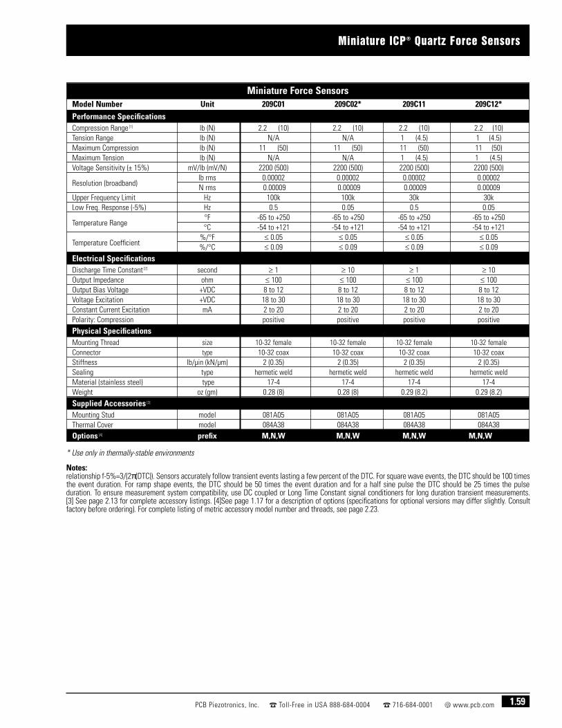
Miniature ICP® Quartz Force Sensors
1.59PCB Piezotronics, Inc. Toll-Free in USA 888-684-0004 716-684-0001 www.pcb.com
Miniature Force SensorsModel Number Unit 209C01 209C02* 209C11 209C12*
Performance SpecificationsCompression Range [1] lb (N) 2.2 (10) 2.2 (10) 2.2 (10) 2.2 (10)Tension Range lb (N) N/A N/A 1 (4.5) 1 (4.5)Maximum Compression lb (N) 11 (50) 11 (50) 11 (50) 11 (50)Maximum Tension lb (N) N/A N/A 1 (4.5) 1 (4.5)Voltage Sensitivity (± 15%) mV/lb (mV/N) 2200 (500) 2200 (500) 2200 (500) 2200 (500)
Resolution (broadband)lb rms 0.00002 0.00002 0.00002 0.00002N rms 0.00009 0.00009 0.00009 0.00009
Upper Frequency Limit Hz 100k 100k 30k 30kLow Freq. Response (-5%) Hz 0.5 0.05 0.5 0.05
Temperature Range°F -65 to +250 -65 to +250 -65 to +250 -65 to +250°C -54 to +121 -54 to +121 -54 to +121 -54 to +121
Temperature Coefficient%/°F ≤ 0.05 ≤ 0.05 ≤ 0.05 ≤ 0.05%/°C ≤ 0.09 ≤ 0.09 ≤ 0.09 ≤ 0.09
Electrical SpecificationsDischarge Time Constant [2] second ≥ 1 ≥ 10 ≥ 1 ≥ 10Output Impedance ohm ≤ 100 ≤ 100 ≤ 100 ≤ 100Output Bias Voltage +VDC 8 to 12 8 to 12 8 to 12 8 to 12Voltage Excitation +VDC 18 to 30 18 to 30 18 to 30 18 to 30Constant Current Excitation mA 2 to 20 2 to 20 2 to 20 2 to 20Polarity: Compression positive positive positive positive
Physical SpecificationsMounting Thread size 10-32 female 10-32 female 10-32 female 10-32 femaleConnector type 10-32 coax 10-32 coax 10-32 coax 10-32 coaxStiffness lb/µin (kN/µm) 2 (0.35) 2 (0.35) 2 (0.35) 2 (0.35)Sealing type hermetic weld hermetic weld hermetic weld hermetic weldMaterial (stainless steel) type 17-4 17-4 17-4 17-4Weight oz (gm) 0.28 (8) 0.28 (8) 0.29 (8.2) 0.29 (8.2)
Supplied Accessories [3]
Mounting Stud model 081A05 081A05 081A05 081A05Thermal Cover model 084A38 084A38 084A38 084A38Options [4] prefix M,N,W M,N,W M,N,W M,N,W
* Use only in thermally-stable environments
Notes: [1] 1 lb = 4.448 N (values shown are approximate) [2] The Discharge Time Constant (DTC) determines low frequency response according to the relationship f-5%=3/(2π(DTC)). Sensors accurately follow transient events lasting a few percent of the DTC. For square wave events, the DTC should be 100 timesthe event duration. For ramp shape events, the DTC should be 50 times the event duration and for a half sine pulse the DTC should be 25 times the pulse duration. To ensure measurement system compatibility, use DC coupled or Long Time Constant signal conditioners for long duration transient measurements. [3] See page 2.13 for complete accessory listings. [4]See page 1.17 for a description of options (specifications for optional versions may differ slightly. Consult factory before ordering). For complete listing of metric accessory model number and threads, see page 2.23.

1.60 PCB Piezotronics, Inc. Toll-Free in USA 888-684-0004 716-684-0001 www.pcb.com
Miniature ICP® Quartz Force Sensors
ICP®
Force SensorConstant Current
Signal ConditionerReadout Device
StandardSensor Cable* Output Cable
* Low-noise cables are required to maintain conformance.
Miniature-Style ICP® Quartz Force Sensor Measurement System
Miniature ICP® Quartz Force Sensors are sensitive enough to capture tiny forces encounteredin biological applications.

Miniature Quartz Force Sensors
1.61PCB Piezotronics, Inc. Toll-Free in USA 888-684-0004 716-684-0001 www.pcb.com
■ Injection molding cavity pressure
■ Push button forces
■ Pin insertion forces
■ Switch and actuator testing
■ Removable cable
Highlights
Miniature charge output quartz forces sensors are designed for industrial applicationswhere space is limited. They are ideal for obtaining an indirect measurement of injection molding cavity pressure by positioning the sensor behind an ejector pin.They measure forces up to 560 lb (4.5 kN) full-scale. The sensor may also be used forother applications involving compression forces, such as push buttons, pin insertion on circuit boards, switches, and actuators.
These sensors feature high stiffness that allows them to follow very fast transientevents. They may also be used to measure short term, quasi-static processes. Theremovable cable allows for a choice of lengths and terminating connector type, andfacilitates easy field repair, in the event a cable is damaged.

Model 219A05■ Sensitivity of 20 pC//b (4.5 pC/N)■ Full-scale compression range to 560 lb (2500 N)■ Compact size of 0.24 inch (6 mm) diameter
and 0.24 inch (6mm) height ■ 0.04 oz (1.2 gm) weight
Recommended cables and accessories ➀ – see page 2.14
Select a charge amplifier from those featured in theelectronics section, starting on page 2.1
Options: none
1.62 PCB Piezotronics, Inc. Toll-Free in USA 888-684-0004 716-684-0001 www.pcb.com
Miniature Quartz Force Sensors
Model 219A05 0.5(12.7)
5-44Connector
0.24(6.0)Dia
0.24(6.0)
Miniature Quartz Force SensorPerformance English SI
Sensitivity (± 15 %) 20 pC/lb 4.5 pC/NMeasurement Range(Compression) 560 lb 2500 N
Maximum Static Force(Compression) 675 lb 3000 N
Upper Frequency Limit 140 kHz [2][3] Non-Linearity ≤ 1 % FS [4] EnvironmentalTemperature Range -300 to +400 °F -184 to +204 °CTemperature Coefficient of Sensitivity ≤ 0.05 %/°F ≤ 0.09 %/°C
ElectricalCapacitance 5 pF [1]Insulation Resistance 1012
Output Polarity (Compression) NegativePhysicalStiffness 3 lb/µin 1.05 kN/µm [1]Size (Diameter x Height) 0.2360in x 0.2362in 6.000mm x 5.995mmWeight 0.042 oz 1.2 gmHousing Material Stainless SteelSealing HermeticElectrical Connector 5-44 CoaxialElectrical Connection Position Side
All specifications are at room temperature unless otherwise specified.
Notes: [1] Typical. [2] Estimated using rigid body dynamics calculations. [3] Low frequencyresponse and system noise dependent on choice of external signal condition electronics. [4] Zero-based, least-squares, straight line method.
Typical System Utilizing Industrial Charge Amplifier
Model 421A25 Industrial Charge Amplifier
■ 1-channel, surface-mount enclosure■ Sixteen selectable input ranges from 100 to 1,000 kpC■ Long discharge time constant for long duration
measurements with an electronic reset option
■ Optional Model 009M146 I/0 cable, 5 ft (1.5m),terminating in pigtails
■ Ideal for continuously monitoring injection moldingoperations
(See section 2 on Model 421A25 for more information)
Readout Device
Model 003P10 Cable
Series 219A05Charge OutputForce Sensor

Penetration-style ICP® Quartz Force Sensors
1.63PCB Piezotronics, Inc. Toll-Free in USA 888-684-0004 716-684-0001 www.pcb.com
■ Material strength testing
■ Drop testing
■ Testing of plastics
■ Penetration testing
Highlights
Penetration-style quartz force sensors measure impact and compression forcesassociated with materials penetration testing. The blunt sensor end makes it possible tomeasure yield and break point forces on materials such as polymers without cuttingthrough the test specimen.
The blunt impact caps are hemispherical to uniformly distribute force and conform tomost penetration testing specifications. Sensors are available with both integral andremovable impact caps. Tension measurements can be made with models havingremovable caps.
These sensors monitor impact forces from 100 to 5000 lb (450 to 22k N) full-scale. Theycan be used to determine physical properties of plastics and material strength ordeformation characteristics of injection molded test specimens and thermal forms. Theymay be installed at the end of a shaft mounted to a driven fixture that impacts the testspecimen.

Models 208A22, 208A23 and 208A24■ Sensitivity ranges from 1 to 50 mV/lb
(0.22 to 11 mV/N)■ Full-scale compression ranges from 100 to
2500 lb (450 to 11k N)■ Integral impact cap
Recommended cables and accessories ➋➁ – see page 2.14
Select an ICP® sensor signal conditioner from thosefeatured in the electronics section, starting on page 2.1
Options: none
Model 208A33■ Sensitivity of 5.0 mV/lb (1.1 mV/N)■ Compression range to 1000 lb (4500 N)■ Tension range to 500 lb (2200 N)■ Removable impact cap
Recommended cables and accessories ➋➁ – see page 2.14
Select an ICP® sensor signal conditioner from thosefeatured in the electronics section, starting on page 2.1
Options: – none
Model 208A35■ Sensitivity of 1.0 mV/lb (0.22 mV/N)■ Compression range to 5000 lb (22k N)■ Tension range to 500 lb (2200 N)■ Removable impact cap
Recommended cables and accessories ➋➁ – see page 2.14
Select an ICP® sensor signal conditioner from thosefeatured in the electronics section, starting on page 2.1
Options: none
Model 208A45■ Sensitivity of 1.0 mV/lb (0.22 mV/N)■ Compression range to 5000 lb (22k N)■ Tension range to 500 lb (2200 N)■ Removable impact cap
Recommended cables and accessories ➋➁ – see page 2.14
Select an ICP® sensor signal conditioner from thosefeatured in the electronics section, starting on page 2.1
Options: none
Dimensions shown are in inches (millimeters).
1.64 PCB Piezotronics, Inc. Toll-Free in USA 888-684-0004 716-684-0001 www.pcb.com
Penetration-Style ICP® Quartz Force Sensors
Penetration(complete specifications are featured on page 1.65)
Penetration-style sensors are used to determine material strength or deformation characteristics of polymers and plastics. Built-inmicroelectronics generate a low-impedance voltage output and a high signal-to-noise ratio. Rugged, stainless steel construction
prolongs life under normal use. Temperature range of -65 to +250 °F(-54 to +121 °C) enables laboratory testing in thermal chamberenvironments. Metric mounting threads are standard for this sensorseries.
■ polymer and plastics testing ■ injection molded specimen testing
Model 208A45
Models 208A22, 208A23 and 208A24
Model 208A33 Model 208A35

Penetration-Style ICP® Quartz Force Sensors
1.65PCB Piezotronics, Inc. Toll-Free in USA 888-684-0004 716-684-0001 www.pcb.com
Penetration-Style Force SensorsModel Number Unit 208A22 208A23 208A24 208A33 208A35 208A45
Performance SpecificationsCompression Range [1] lb (N) 100 (450) 1000 (4500) 2500 (11k) 1000 (4500) 5000 (22k) 5000 (22k)Tension Range lb (N) N/A N/A N/A 500 (2200) 500 (2200) 500 (2200)Maximum Compression lb (N) 600 (2700) 2500 (11k) 2500 (11k) 5000 (22k) 10k (45k) 10k (45k)Maximum Tension lb (N) N/A N/A N/A 750 (3300) 750 (3300) 750 (3300)Voltage Sensitivity (± 15%) mV/lb (mV/N) 50 (11) 5 (1.1) 1 (0.22) 5 (1.1) 1 (0.22) 1 (0.22)Resolution (broadband) lb rms (N) rms 0.002 (0.009) 0.02 (0.09) 0.10 (0.45) 0.02 (0.09) 0.10 (0.45) 0.10 (0.45)Amplitude Linearity % FS ≤ 1 ≤ 1 ≤ 1 ≤ 1 ≤ 1 ≤ 1Upper Frequency Limit Hz 18k 18k 18k 20k 20k 25kLow Freq. Response (-5%) Hz 0.003 0.0003 0.0003 0.0003 0.0003 0.0003
Temperature Range°F -65 to +250 -65 to +250 -65 to +250 -65 to +250 -65 to +250 -65 to +250°C -54 to +121 -54 to +121 -54 to +121 -54 to +121 -54 to +121 -54 to +121
Temperature Coefficient%/°F ≤ 0.03 ≤ 0.03 ≤ 0.03 ≤ 0.03 ≤ 0.03 ≤ 0.03%/°C ≤ 0.054 ≤ 0.054 ≤ 0.054 ≤ 0.054 ≤ 0.054 ≤ 0.054
Electrical SpecificationsDischarge Time Constant [2] second ≥ 200 ≥ 2000 ≥ 2000 ≥ 2000 ≥ 2000 ≥ 2000Output Impedance ohm ≤ 100 ≤ 100 ≤ 100 ≤ 100 ≤ 100 ≤ 100Output Bias Voltage +VDC 8 to 14 8 to 14 8 to 14 8 to 14 8 to 14 8 to 14Voltage Excitation +VDC 20 to 30 20 to 30 20 to 30 20 to 30 20 to 30 20 to 30Constant Current Excitation mA 2 to 20 2 to 20 2 to 20 2 to 20 2 to 20 2 to 20Polarity: Compression positive positive positive positive positive positive
Physical Specifications Mounting Thread size M7 x 0.75 male M7 x 0.75 male M7 x 0.75 male M7 x 0.75 male M7 x 0.75 male M7 x 0.75 maleConnector type 10-32 coax 10-32 coax 10-32 coax 10-32 coax 10-32 coax 10-32 coaxStiffness lb/µin (kN/µm) 5 (0.88) 5 (0.88) 5 (0.88) 5 (0.88) 5 (0.88) 10 (1.75)Sealing type o-ring o-ring o-ring epoxy hermetic weld epoxyMaterial (stainless steel) type 316L / 17-4 316L / 17-4 316L / 17-4 316L / 17-4 17-4 316L / 17-4Impact Cap Material type titanium titanium titanium 17-4 st. stl. 17-4 st. stl. 17-4 st. stl.Weight oz (gm) 0.53 (15) 0.53 (15) 0.53 (15) 0.67 (19) 1.06 (30) 1.80 (51)
Supplied Accessories [3]
Impact Cap model integral integral integral 084A19 084A35 084A45
Notes: [1] 1 lb = 4.448 N (values shown are approximate) [2] The Discharge Time Constant (DTC) determines low frequency response according to the relationship f-5%=3/(2π(DTC)). Sensors accurately follow transient events lasting a few percent of the DTC. For square wave events, the DTC should be 100 timesthe event duration. For ramp shape events, the DTC should be 50 times the event duration and for a half sine pulse the DTC should be 25 times the pulse duration. To ensure measurement system compatibility, use DC coupled or Long Time Constant signal conditioners for long duration transient measurements. [3] See page 2.13 for complete accessory listings.

1.66 PCB Piezotronics, Inc. Toll-Free in USA 888-684-0004 716-684-0001 www.pcb.com
Penetration-Style ICP® Quartz Force Sensors
Penetration-style quartz force sensors measure impact forces to 5000 lb (22k N) for determiningyield strength and deformation characteristics of plastics, polymers, and composite materials.
ICP® Force Sensor
Constant CurrentSignal Conditioner
Readout Device
StandardSensor Cable* Output Cable
* Low-noise cable is required to maintain conformance.
Penetration-Style ICP® Quartz Force Sensor Measurement System

ICP® Strain Sensors
1.67PCB Piezotronics, Inc. Toll-Free in USA 888-684-0004 716-684-0001 www.pcb.com
■ Measure longitudinal strain on machinery structures
■ Control press forces and other processes
■ Monitor quality, safety, and reliability
■ Robust construction endures harsh, industrial environments
■ Simple installation is non-invasive to process
Highlights
The Series M240 Industrial ICP® Strain Sensors incorporate piezoelectric quartz sensingcrystals that respond to a longitudinal change in distance. The resultant strainmeasurand is an indirect measurement of stress forces acting along the structure towhich the sensor is mounted. As such, these devices can provide insight into the behavior of mechanical systems or processes that generate an associated machineryreaction.
Monitoring such measurement signals can provide the necessary indication for processinterrupt and pass/fail decisions or for determining wear and degradation of equipmentand tooling. The sensors are used for controlling processes in plastic injection molding,spot welding, stamping, and pressing, as well as monitoring processes and final productquality. These devices are easy to install and can be powered by any ICP® sensor signalconditioner.

1.14(29.0)
0.60(15.2)
1.58(40.1)
0.23(5.8)
0.18(4.6)
0.67(17.0)
10-32 Connector
M6 MountingScrew (supplied) M081A100
1.68 PCB Piezotronics, Inc. Toll-Free in USA 888-684-0004 716-684-0001 www.pcb.com
ICP® Strain Sensors
ICP® Strain Sensors(complete specifications are featured on page 1.69)
Series M240 ICP® Strain Sensors are ideal for process control andother product quality assurance applications that require themeasurement of repetitive strain curves. In typical applications,upper and lower control limits are set following a desired straincurve for the process, and if the actual strain curve deviates from thepre-set control limits, the process or equipment is shut down. This prevents the acceptance of non-conforming parts as finishedgoods. ICP® strain sensors are used for controlling processes inplastic injection molding, spot welding, stamping, pressing,
punching, crimping, forming, and automatic assembly operations.Sensors are constructed of rugged stainless steel housings, areextremely easy to install (using only one supplied fastening screw),and are non-invasive to the test structure except for one drilled andtapped hole. Series M240 Strain Sensors can be powered by anyICP® sensor signal conditioner.
■ mechanical stamping, crimping, ■ automatic assembly pressing, and punching presses machines
■ forming and other machine tools ■ plastic injection■ spot welding molding machines
Model M240A01■ Sensitivity (± 20%) of 100 mV/µe■ Amplitude range to 50 pk µe ■ Resolution (1 Hz to 10 kHz) to 0.0001 µe■ Discharge time constant of ≥ 150 seconds
Recommended cables and accessories ➋➁ – see page 2.14
Select an ICP® sensor signal conditioner from thosefeatured in the electronics section, starting on page 2.1
Options: J, W – see page 1.17 for option information
Model M240A02■ Sensitivity (± 20%) of 50 mV/µe ■ Amplitude range to 100 pk µe ■ Resolution (1 Hz to 10 kHz) to 0.0002 µe■ Discharge time constant of ≥ 150 seconds
Recommended cables and accessories ➋➁ – see page 2.14
Select an ICP® sensor signal conditioner from thosefeatured in the electronics section, starting on page 2.1
Options: J, W – see page 1.17 for option information
Model M240A03■ Sensitivity (± 20%) of 10 mV/µe ■ Amplitude range to 300 pk µe ■ Resolution (1 Hz to 10 kHz) to 0.001 µe■ Discharge time constant of ≥ 150 seconds
Recommended cables and accessories ➋➁ – see page 2.14
Select an ICP® sensor signal conditioner from thosefeatured in the electronics section, starting on page 2.1
Options: J, W – see page 1.17 for option information
Dimensions shown are in inches (millimeters).
Series M240 Industrial ICP® Strain Sensors

ICP® Strain Sensors
1.69PCB Piezotronics, Inc. Toll-Free in USA 888-684-0004 716-684-0001 www.pcb.com
Typical ICP® Strain Sensor Measurement System
ICP® Strain SensorsModel Number Unit M240A01 M240A02 M240A03
Performance SpecificationsRange pk µε 50 100 300Sensitivity (± 20%) mV/µε 100 50 10Resolution (1 Hz to 10 kHz) µε 0.0001 0.0002 0.001Low Frequency Response (-5%) Hz 0.004 0.004 0.004Linearity % ± 2 ± 2 ± 2Operating Temperature °F (°C) -65 to +250 (-54 to +121) -65 to +250 (-54 to +121) -65 to +250 (-54 to +121)
Electrical SpecificationsExcitation Voltage +VDC 20 to 30 20 to 30 20 to 30Constant Current Excitation mA 2 to 20 2 to 20 2 to 20Output Bias Voltage +VDC 8 to 14 8 to 14 8 to 14Discharge Time Constant sec ≥ 150 ≥ 150 ≥ 150
Physical SpecificationsSensing Element quartz quartz quartzHousing material stainless steel stainless steel stainless steel Size (W x L x H) in (mm) 0.67 x 1.81 x 0.6 (17 x 46 x 15.2) 0.67 x 1.81 x 0.6 (17 x 46 x 15.2) 0.67 x 1.81 x 0.6 (17 x 46 x 15.2) Weight oz (gm) 1.6 (45) 1.6 (45) 1.6 (45)Electrical Connector type 10-32 10-32 10-32Sealing type epoxy epoxy epoxyM081A100 Mounting Screw (supplied) M6 x 1.00-6g M6 x 1.00-6g M6 x 1.00-6gMounting Screw Torque ft-lb (N-m) 7.38 (10) 7.38 (10) 7.38 (10)
Options Prefix J,W J,W J,W
* Low-noise cables are required to maintain conformance.
Readout Device
ICP® Sensor Signal Conditioner
ICP® StrainSensor
Output Cable
StandardSensor Cable
Readout Device
PLC
Model 410A01 DINRail ICP® Sensor
Signal Conditioner
ICP® StrainSensor
CustomerSupplied
AWG 14-24 WIRE
Model002EB010JE
Cable

1.70 PCB Piezotronics, Inc. Toll-Free in USA 888-684-0004 716-684-0001 www.pcb.com
ICP® Strain Sensors
Series M240 Strain SensorsMonitor and Control Weld Forces to Ensure Quality End Products.
ICP® strain sensors indirectly monitor forces via strain measurements on machine toolsand production machinery. Strain sensors are used for controlling processes in spotwelding, plastic injection molding, stamping, pressing, punching, crimping, forming, andautomatic assembly operations. Series M240 Strain Sensors may be powered by anyICP® sensor signal conditioner.

Signal Conditioners
2.1PCB Piezotronics, Inc. Toll-Free in USA 888-684-0004 716-684-0001 www.pcb.com
■ Battery powered
■ Line powered
■ Multi-purpose
■ Modular-style
■ Multi-channel
■ Charge & impedance converters
■ Industrial charge amplifiers & sensor simulators
Highlights

2.2 PCB Piezotronics, Inc. Toll-Free in USA 888-684-0004 716-684-0001 www.pcb.com
Battery Powered Signal Conditioners for ICP® Sensors
Battery Powered ICP® Sensor Signal ConditionersBattery powered signal conditioners offer portable, convenientmethods for powering ICP® sensors and conditioning their outputsignals for transmittal to readout and recording instruments. Most
units operate, and are supplied, with standard 9 volt alkalinebatteries. Each features a color-coded input circuit check-out meterto alert of proper sensor turn-on or input fault due to open or short-circuit connections. Optional rechargeable versions areequipped with NiCad batteries and supplied with an AC poweredrecharger unit.
Model 480C02Unity gain, low- noise, high frequency
Model 480E09Gain x1, x10, x100
Model 480B213-Channel, gain x1, x10, x100
Note: [1] With 1 megohm load.
Battery Powered ICP® Signal ConditionersModel Number 480C02 480E09 480B21
Style Basic Gain 3 channel with gain
Channels 1 channel 1 channel 3 channelsSensor excitation 28 VDC, 2.5 mA 28 VDC, 2.5 mA 25 to 30 VDC, 3 mAGain unity x1, x10, x100 x1, x10, x100Low frequency response (-5%) [1] 0.05 Hz 0.15 Hz 0.15 HzHigh frequency response (-5%) 500k Hz 100k Hz 90k HzBroadband noise (at unity gain) 3.25 µV rms 3.25 µV rms 3.54 µV rmsBattery (qty) type (3) 9 V (3) 9 V (3) 9 VAverage battery life 100 hour 40 hour 25 to 40 hourInput/output connectors BNC/BNC BNC/BNC BNC/BNCExternal DC powerable yes yes yesDC power input jack 3.5 mm 3.5 mm mini DIN 6-pin jack
Size (height x width x depth)4.0 x 2.9 x 1.5 in 4.0 x 2.9 x 1.5 in 7.5 x 5 x 2 in
(10 x 7.4 x 3.8 cm) (10 x 7.4 x 3.8 cm) (19.1 x 12.7 x 5.1 cm)Weight 0.62 lb (284 g) 0.75 lb (341 g) 1.1 lb (499 g)
Optional ModelsRechargeable R480C02 R480E09 N/A(supplied with Ni-cad batteries andModel 488A02 AC powered recharger unit)
OptionsAC powered recharger unit with 488A02 488A02 N/A(3) 9 V Ni-cad batteriesAC power supply operates 488A03 488A03 488A10from 115 or 230 VAC

Line Powered Signal Conditioners for ICP® Sensors
2.3PCB Piezotronics, Inc. Toll-Free in USA 888-684-0004 716-684-0001 www.pcb.com
Line Powered ICP® Sensor Signal ConditionersLine powered signal conditioners offer bench-top methods forpowering ICP® sensors in the laboratory and conditioning theiroutput signals for transmittal to readout and recording instruments.Each features a color-coded input circuit checkout meter to alert of
proper sensor turn-on or input fault due to open or short-circuitconnections. AC and DC powerable units can operate either withthe supplied AC powered transformer or optional external batterypack. AC/DC coupled outputs offer the ability to achieve true DCfrequency response in order to accurately condition very lowfrequency vibrations or long duration shock pulses.
Model 482A21Unity gain, low-noise,AC and DC powerable
Model 482A224-channel, unity gain,low-noise, AC and DCpowerable
Model 482B06Basic, unity gain
Model 482B11Gain x1, x10, x100
Model 484B02Clamped output, unity gain, AC/DC coupled output
Model 484B06Low frequency, unitygain, AC/DC coupledoutput
Model 484B11Low frequency, gain x1, x10, x100, AC/DC coupled output
Note: 1. Current is factory set at 4 mA but is user adjustable between 2 and 20 mA 2. With 1 megohm load 3. Supplied with Model 488A04 AC power adaptor(100 to 240 VAC, 50 to 60 Hz input; 36 VDC 120 mA output)
Line Powered ICP® Signal ConditionersModel Number 482A21 482A22 482B06 482B11 484B02 484B06 484B11
StyleLow-noise Low-noise
Basic GainClamped output Low frequency Low frequency
AC and DC power AC and DC power AC/DC coupled AC/DC coupled with gainChannels 1 channel 4 channels 1 channel 1 channel 1 channel 1 channel 1 channelSensor excitation [1] 26 volt, 2 to 20 mA 26 volt, 2 to 20 mA 24 volt, 2 to 20 mA 24 volt, 2 to 20 mA 24 volt, 2 to 20 mA 24 volt, 2 to 20 mA 24 volt, 2 to 20 mAGain unity unity unity x1, x10, x100 unity unity x1, x10, x100Low frequency response (-5%) <0.1 Hz [2] <0.1 Hz [2] <0.05 Hz 0.17 Hz DC DC DCHigh frequency response (-5%) >1M Hz >1M Hz 1M Hz 200k Hz 200k Hz 200k Hz 200k HzBroadband noise (at unity gain) <3.25 µV rms <3.25 µV rms <3.64 µV rms N/A 28.8 µV rms 28.8 µV rms 10 µV rms
Power required36 VDC 36 VDC 115 VAC 115 VAC 115 VAC 115 VAC 115 VAC
120 mA [3] 120 mA [3] 50 to 400 Hz 50 to 400 Hz 50 to 400 Hz 50 to 400 Hz 50 to 400 HzInput/output connectors BNC/BNC BNC/BNC BNC/BNC BNC/BNC BNC/BNC BNC/BNC BNC/BNCExternal DC powerable yes yes no no no no noDC power input jack DIN DIN — — — — —
Size (height x width x depth)6.3 x 2.4 x 11 in 6.3 x 2.4 x 11 in 4.3 x 1.8 x 6 in 4.3 x 1.8 x 6 in 5 x 2 x 10.5 in 4.3 x 1.8 x 6 in 4.3 x 1.8 x 6 in
(16 x 6 x 28 cm) (16 x 6 x 28 cm) (11 x 4.6 x 15 cm) (11 x 4.6 x 15 cm) (12.7 x 5.1 x 26.7 cm) (11 x 4.6 x 15 cm) (11 x 4.6 x 15 cm)Weight 1.51 lb (685 gm) 1.67 lb (756 gm) 1.2 lb (544 gm) 2 lb (907 gm) 2 lb (907 gm) 2 lb (907 gm) 2 lb (907 gm)
Optional Models210 to 250 VAC powerable standard standard F482B06 F482B11 F484B02 F484B06 F484B11
OptionsExternal 36 VDC battery pack 488B07 488B07 N/A N/A N/A N/A N/A

2.4 PCB Piezotronics, Inc. Toll-Free in USA 888-684-0004 716-684-0001 www.pcb.com
DIN Rail Signal Conditioners for ICP® Sensors
Model 410A01The Model 410A01 DIN rail mount, ICP® SensorSignal Conditioner, for piezoelectric force orstrain sensors, is ideally suited for monitoringmanufacturing forces experienced duringassembly & product testing. With its longdischarge time constant, and high frequencyresponse, both quasi-static and dynamicmeasurements up to 10 kHz are possible. The unit synchronizes with machine cycles through areset feature while analog and peak hold outputsallow for real-time monitoring with machinecontrol devices. Requires 24 VDC power.
Model 682A02The Model 682A02 DIN rail mount, ICP® SignalConditioner provides 18 VDC sensor excitationvoltage for dynamic measurements only. Internaljumpers select excitation current of 4 or 10 mAand voltage gain of x1, x10, or x100.
Model 682A0124 VDC Power Supply, 120 to 230 VAC powered,DIN rail mount, 3.75 kV isolation, 1,000 mAmaximum.
Model 682A06Programmable, universal transmitter withcurrent, voltage, and two relay outputs. AcceptsmA, VDC, RTD, TC, linear resistance, andpotentiometer inputs. Fully programmable viadetachable display (Model 070A80 soldseparately), and operates from 19.2 to 300 VDC,or 21.5 to 253 VAC power.
These products conform to applicable EuropeanDirectives for CE marking.
DIN rail mount signal conditioners offer a convenient mountingpackage for industrial applications. Signal conditioners may bemounted inside protected enclosures or in a control panel for easyaccess to sensor and power supply connections, and integrationwith machine controllers.
The signal conditioners are designed for operation with ICP® force orstrain sensors and are ideally suited for monitoring forcesexperienced during manufacturing, assembly, on-line processes,quality assurance, or end-of-line product testing.

DIN Rail Signal Conditioners for ICP® Sensors
2.5PCB Piezotronics, Inc. Toll-Free in USA 888-684-0004 716-684-0001 www.pcb.com
DIN Rail Signal Conditioners for ICP® Sensors
Model 410A01 [1] 682A02 [1]Performance English (SI)Channels 1 1Excitation Voltage (±1 VDC) 18 VDC 18 VDC [2]Excitation Current (±1 mA) 4 mA 4/10 mAOutput Voltage (Instantaneous) ± 10 V ± 5 VOutput Voltage (Peak) 0 to 10 V -High Frequency Response 10 kHz 100 kHzLow Frequency Response, AC coupled (-5 %) 0.5 Hz 1.25 HzLow Frequency Response, DC coupled 0 Hz [3] DC coupling not availableVoltage Gain (Incremental Steps) x0.5, x1, x2, x4, x8, x10, x16, x20 x1, x10, x100
EnvironmentalTemperature Range (Operating) +60 to +110 °F (+15 to +45 °C) +32 to +158 °F (+0 to +70 °C)
ElectricalPower Required (± 10%) 24 VDCCurrent Draw 100 mA 60 mABroadband Electrical Noise (1 Hz to 10 kHz) 20 µV rms 50 µV rmsPeak Hold Reset Solid State Relay -Discharge Time Constant (AC coupled) 1 sec 0.4 sec
PhysicalSize (Length x Height x Width) 3.6 x 4.4 x 0.9 in (91 x 112 x 23 mm) 3.1 x 4.3 x 1.0 in (79 x 84 x 25 mm)Mounting DIN RailElectrical Connector (Sensor Input) SMA Screw TerminalsElectrical Connector (Analog Output, Screw TerminalsPeak Output, Power, Ground)
Notes: [1] This product conforms to applicable European Directives for CE marking. [2] If unit is used in conjunction with a sensor having a bias over 13 VDC, fullscale output may be affected. [3] In DC coupled mode, system low frequency response is determined by the sensor.

2.6 PCB Piezotronics, Inc. Toll-Free in USA 888-684-0004 716-684-0001 www.pcb.com
Modular-Style Signal Conditioners
Modular signal conditioners are comprised of selected signal conditioning modules, andan AC power supply module, assembled into a 2-, 3-, 5-, or 9-slot chassis. Availablemodules condition ICP®, charge output, or capacitive sensor signals. The commonchassis backplane architecture permits mixing and matching of modules to achieve thedesired number of channels and signal conditioning features. Visit www.pcb.com for fulldetails of available items.
Modular-Style Signal Conditioners
Modular Signal Conditioning Systems
Modular-Style Signal Conditioners
Model 442B21616-channel, unity gain,with selectable ICP® orvoltage mode
Model 442B31616-channel, unity gain,with selectable ACcoupled ICP® or DCcoupled voltage mode
Model 442C044-channel, gain x1,x10, x100 for ICP®
sensors
Model 443B02Dual mode amplifierfor charge output andICP® sensors withshort, medium andlong discharge timeconstants
Modular-Style Signal ConditionersModel Number 442B216 442B316 442C04 443B02 [6]
Channels 16 channels 16 channels 4 channels 1 channelSensor excitation [1] 22 volt, 2 to 10 mA 22 volt, 2 to 10 mA 25.5 volt, 0.5 to 20 mA 24 volt, 0 to 20 mA [2]
Gain (each channel) x1 x1 x1, x10, x100 x0.1 to 1000Charge sensitivity N/A N/A N/A 0.0001 to 10 volts/pCLow frequency response (-5%) 0.125 Hz 0.125 Hz 0.05 Hz [3] 2, 0.2, 0.03, 0.003, ~0 Hz [4]
High frequency response (-5%) 30k Hz 30k Hz 100k Hz 0.1, 1, 3, 10, 100, >200k Hz [5]
Broadband noise (at unity gain) 100 µV rms 100 µV rms 10 µV rms 9 µV rms
Power required100 to 240 VAC 100 to 240 VAC 100 to 240 VAC 100 to 240 VAC
50 to 60 Hz 50 to 60 Hz 50 to 60 Hz 50 to 60 HzInput/output connectors DB-50 Female/Quad Agilent E1432 DB-50 Female/Quad Agilent E1432 BNC/BNC BNC/BNC
Size (height x width x depth)5.05 x 3.6 in [7] 5.05 x 3.6 in [7] 6.2 x 4.25 x 10.2 in 6.2 x 6.05 x 10.2 in
(128.3 x 91.4 mm) (128.3 x 91.4 mm) (15.7 x 10.8 x 26 cm) (15.7 x 15.4 x 26 cm)Weight 0.95 lb (0.43 kg) 0.95 lb (0.43 kg) 5.1 lb (2.3 kg) 6.4 lb (2.9 kg)
Notes: [1] Current is factory set at 4 mA but is user adjustable up to 20 mA. [2] Excitation is disabled for charge output sensor input. [3] With 1 megohmload. [4] Adjusted by discharge time constant and high-pass filter selection. [5] Adjusted by low-pass filter selection. [6] Charge input range for Model 443B02is limited to 100k pC. For high sensitivity charge output force sensors, use appropriate Series 472B charge attenuator to achieve desired full-scale force rangewhere necessary. See page 1.68. [7] Conforms to Series 440 Modular System.

2.7PCB Piezotronics, Inc. Toll-Free in USA 888-684-0004 716-684-0001 www.pcb.com
Multi-Channel Signal Conditioners
Modular-Style Signal Conditioners
Multi-Channel Signal ConditionersMulti-channel rack mount signal conditioners contain 8- or 16-channels of simultaneous signal conditioning and can be configuredfor multiple unit, daisy-linking with computerized set up and control.The building block-style architecture permits factory configuration toinclude characteristics which best tailor a unit for the specificapplication and data acquisition requirements. Standard featuresinclude ICP® sensor excitation and LED indicators for input faultmonitoring and overload detection. Optional features include
programmable gain, autoranging, filtering, output switching,integration, IEEE-488, RS-232, and RS-485 interface, and keypadcontrol with LCD display. Units are available to condition signalsfrom ICP® and charge output sensors, or can be set up to acceptvoltage input signals from other types of sensors. Pre-configuredmodels offer ease of ordering units possessing the most commonlyrequested features. Visit www.pcb.com for full details of availableitems.
All Models available in 8- or 16-channel custom configurations All Models available in 8- or 16-channel custom configurations
Model 481A0216-channel, gain x1,x10, x100 for ICP®
sensors
Model 481A0316-channel, continuousgain x0.1 to x200for ICP® sensors
Model 481A0116-channel, unity gainfor ICP® sensors
Model 481A2016-channel, unity gainfor ICP® sensors
Note: [1] Current is factory set at 4 mA but is user adjustable between 3 and 20 mA. [2] Attains 90k Hz with filter disabled. [3] Supplied with Windows®
based control software program.
Multi-Channel Signal ConditionersModel Number 481A01 481A02 481A03 481A20
Style unity gainselectable gain continuous gain adjust
unity gainwith keypad & display with keypad & displayChannels 8 or 16 8 or 16 8 or 16 8 or 16Sensor excitation [1] 24 volt, 3 to 20 mA 24 volt, 3 to 20 mA 24 volt, 3 to 20 mA 24 volt, 3 to 20 mA
Gain (each channel) unityautoranging continuous
unityx1, x10, x100 x0.1 to x200Frequency response (± 5%) 0.5 to 100k Hz 0.5 to 100k Hz 0.5 to 90k Hz [2] 0.05 to 1M HzBroadband noise (at unity gain) 11 µV rms 11 µV rms 4 mV 11 µV rms
Power required100 to 240 VAC 100 to 240 VAC 100 to 240 VAC 100 to 240 VAC
47 to 63 Hz 47 to 63 Hz 47 to 63 Hz 47 to 63 HzKeypad control no yes yes noComputer control no RS-232 and RS-485 [3] RS-232 and RS-485 [3] noInput connectors DB50 and BNC DB50 and BNC DB50 and BNC BNCOutput connectors DB37 and BNC DB37 and BNC DB37 and BNC BNC
Size (height x width x depth)3.5 x 19.0 x 16.25 in 3.5 x 19.0 x 16.25 in 3.5 x 19.0 x 16.25 in 3.5 x 19.0 x 16.25 in
(9 x 48 x 41 cm) (9 x 48 x 41 cm) (9 x 48 x 41 cm) (9 x 48 x 41 cm)Weight 15 lb (6.8 kg) 15 lb (6.8 kg) 15 lb (6.8 kg) 15 lb (6.8 kg)

2.8 PCB Piezotronics, Inc. Toll-Free in USA 888-684-0004 716-684-0001 www.pcb.com
Charge and Impedance Converters
Series 422E charge converters serve to convert charge output sensor signals to low-impedance voltage signals, for transmission over long cables, and interface to data acquisitionequipment. They are low in noise, powered by standard ICP® sensor signal conditioners,and install in-line between the sensor and signal conditioner. Charge converters with signalconditioners offer a less expensive technique, compared to the use of laboratory-style chargeamplifiers, and are an especially attractive approach for multi-channel requirements. Likecharge amplifiers, charge converters also invert the polarity of the measurement signal.
Impedance Converters and In-Line Voltage Follower AmplifiersSeries 402A In-line voltage follower amplifiers, similar to the Series 422E chargeconverters, serve to convert charge output sensor signals to low-impedance voltagesignals. They are recommended for applications requiring high frequency response up to1 MHz, and for applications where sensor output (pC/unit) exceeds the maximum inputrange (pC) allowed in the Series 422E.The voltage sensitivity, V, of a system including a charge output sensor, low-noise cableand voltage follower amplifier can be determined mathematically by the equation V=Q/Cwhere Q is the charge sensitivity of the sensor in Coulombs and C is the total systemcapacitance in Farads. The total system capacitance is the result of the sum of thecapacitance of the sensor, the capacitance of the interconnect cable, and the inputcapacitance of the voltage amplifier. Choose a voltage follower amplifier with an inputcapacitance that provides the sensitivity desired, while keeping the total output voltage(range x sensitivity) within the ±10 volt limit. Voltage follower amplifiers do not invert thepolarity of the measurement signal.
Charge Converters
Series 422E
Contact factory for custom ranges and information regarding Series 422M.
Series 402
Note: [1] High frequencyachieved at 20 mA excitation
NOTE: [1] High frequencyachieved at 20 mA excitation
Inverting Charge Converters for Use with Charge Output SensorsCharge Converter Models 422E11 422E12 422E13Gain 100 mV/pC ± 5% 10 mV/pC ± 2% 1 mV/pC ± 2%Input range ± 2% ± 25 pC ± 250 pC ± 2500 pCOutput voltage range ± 3 volts ± 3 volts ± 3 voltsFrequency response (± 5%) [1] 5 to 110k Hz 5 to 100k Hz 5 to 100k HzBroadband noise 60 µV rms 20 µV rms 11 µV rmsPower required 18 to 28 VDC 18 to 28 VDC 18 to 28 VDCConstant current required 2.2 to 20 mA 2.2 to 20 mA 2.2 to 20 mAInput connector 10-32 jack 10-32 jack 10-32 jackOutput connector BNC jack BNC jack BNC jack
Size (length x diameter) 3.4 x 0.5 in 3.4 x 0.5 in 3.4 x 0.5 in(8.6 x 1.3 cm) (8.6 x 1.3 cm) (8.6 x 1.3 cm)
Weight 1.1 oz (31g) 1.1 oz (31g) 1.1 oz (31g)Optional Models0.5 Hz (-5%) low frequency 422E01 422E02 422E03
Non-Inverting Voltage Follower Amplifiers and Impedance Converters for Use with Charge Output Sensors
Voltage Follower Models 402A 402A02 402A03Voltage gain (± 2%) 0.98 0.98 0.98Output Range ± 10 V ± 10 V ± 10 VInput Capacitance < 8.0 pF 100 ± 10% pF 1000 ± 10% pFDischarge time constant 1.0 second 10 second 100 secondFrequency response (± 5%) [1] 0.5 to 1M Hz 0.05 to 1M Hz 0.005 to 1M HzBroadband noise 43 µV rms 43 µV rms 43 µV rmsOutput bias 9 to 13 V 9 to 13 V 9 to 13 V
Temperature range -65 to +250 °F -65 to +250 °F -65 to +250 °F(-54 to +121 °C) (-54 to +121 °C) (-54 to +121 °C)
Power required 18 to 28 VDC 18 to 28 VDC 18 to 28 VDCConstant current required 2 to 20 mA 2 to 20 mA 2 to 20 mAInput connector 10-32 jack 10-32 jack 10-32 jackOutput connector 10-32 jack 10-32 jack 10-32 jack
Size (length x diameter) 1.17 x 0.25 in 1.17 x 0.25 in 1.17 x 0.25 in(28 x 6 mm) (28 x 6 mm) (28 x 6 mm)

Industrial Charge Amplifiers
2.9PCB Piezotronics, Inc. Toll-Free in USA 888-684-0004 716-684-0001 www.pcb.com
Series 421A industrial charge amplifiers are designed for piezoelectric charge outputforce or strain sensors, and are ideally suited for monitoring manufacturing forcesexperienced during assembly, crimping, injection molding, stamping or product testing.With their long discharge time constant and high frequency response, both quasi-staticand dynamic measurements are possible. Each model synchronizes with machine cyclesthrough a reset feature while analog, peak or alarm outputs allow for real-time monitoring.
The single channel Model 421A11 and 3-channel Model 421A13 are packaged in arugged, surface mount, CE marked, sealed aluminum enclosure and are ideal for fixedinstallations in a factory environment. Set up via internal adjustments prohibits tamperingonce it is sealed and deployed. Additional features include electrical ground isolation,high vibration resistance, and a cord grip for securing the supplied, 10 ft (3 m) interfacingcable. The 3-channel Model 421A13 is a cost-effective configuration that supports usewith charge output, 3-component force sensors and force links.
Industrial Charge Amplifiers, Analog Output OnlyModel 421A11 421A13Channels 1 3
± 100 to 1000 pC (Range I) Input Ranges (selectable for each channel) ± 1000 to 10k pC (Range II)
± 10k to 100k pC (Range III) 5 mV/pC (Range I)
Sensitivity 0.50 mV/pC (Range II)0.05 mV/pC (Range III)
Maximum Output 5 VAC~ 0 to 4000 Hz (Range I)
Frequency range (-5%) ~ 0 to 10k Hz (Range II)~ 0 to 12k Hz (Range III)
Broadband noise [1] 11 µVTemperature Range (Operating) +23 to +140 °F (-5 to +60 °C)Power required 15 to 30 VDC, < 19 mA 15 to 30 VDC, < 37 mAInput connector [2] BNC jackOutput connector [3] Screw Terminal
Size4.89 x 1.18 x 2.52 in 6.95 x 1.18 x 2.52 in(124.2 x 30 x 64 mm) (176.5 x 30 x 64 mm)
Weight [4] 0.915 lb (415.04 gm) 1.320 lb (598.7 gm)
Notes: [1] Noise measurements performed at 10k-100k pC range. [2] Optional TNC jack on input,order as Model 421A11/A or 421A13/A. Optional 10-32 (micro) connector on input, order as Model 421A11/B or 421A13/B. [3] Supplied with 10 ft (3 m) multi-conductor cable & PG-9 cord grip. [4] Including multi-conductor cable.
Model 421A13
Model 421A11

2.10 PCB Piezotronics, Inc. Toll-Free in USA 888-684-0004 716-684-0001 www.pcb.com
Industrial Charge Amplifiers
Industrial Charge Amplifier, Analog, Peak and Alarm OutputsModel 421A25Channels 1Input Range (adjustable) ± 100 to ±1,000,000 pCOutput Voltage (Instantaneous) ± 10 VOutput Voltage (Peak) 0 to 10 VFrequency Response (-3 dB) (″ 100k pC) ~0 to 20 kHzFrequency Response (-3 dB) (< 100k pC) ~0 to >2 kHzAccuracy <± 1% FSNon-Linearity <0.02 % FSControl Input ± 5 to 45 VAlarm Output 45 V, 100mATemperature Range (Operating) +23 to +140 °F (-5 to +60 °C)Power Required 15 to 35 VDCCurrent Draw <70mABroadband Electrical Noise <20 mV ppOutput Resisitance 10 ohmDrift <0.03 pC/sDC Offset (max) ± 10 mVSize (l x w x h) – Overall 3.9 x 3.1 x 1.3 in (98 x 79 x 34 mm)Enclosure Material AluminumElectrical Connector (input) BNC JackElectrical Connector (output, setup,
25-Pin D-Subcontrol, power)OptionsInput/Output Connector, 25 pin D-Sub JCInput/Output Cable, 25 pin D-Sub to pigtails,
009M1465ft. (1.5m) length
Note: This product conforms to applicable European Directives for CE marking.
Model 421A25 features 13 fixed input ranges, 3 additional ranges with continuous gainadjustment, analog and peak hold outputs, and 2 adjustable set points that trigger digitalalarm outputs when levels are exceeded. An integral test function enables a check of themeasuring chain without a sensor being connected. All adjustments are set by eitherremote control or RS-232 interface, and the settings are maintained when the power isdisconnected. The RS-232 may also be used to transfer measurement data. The unit ispackaged in a rugged, CE marked aluminum enclosure, well suited for harsh industrialenvironments.
Model 421A25

Electronic Accessories
2.11PCB Piezotronics, Inc. Toll-Free in USA 888-684-0004 716-684-0001 www.pcb.com
Series 472B Charge AttentuatorsSeries 472B charge attenuators are used in conjunction with high-sensitivity chargeoutput force sensors when their full-scale output range exceeds the charge input limit ofthe charge amplifier or converter with which it is used. Series 472B charge attenuatorsserve to divide the output signal delivered by the force sensor by the factor indicated inthe table at left.
ICP® Sensor SimulatorModel 492B ICP® sensor simulator installs in place of an ICP® sensor and serves toverify signal conditioning settings, cable integrity, and tune long lines for optimumsystem performance. By use of an internal oscillator, the unit delivers a 100 Hz sine orsquare wave at a selectable peak to peak voltage. External test signals from a functiongenerator may also be inserted. This portable unit is battery powered.
Model 401A04 ICP® sensor simulator installs in place of an ICP® sensor and accepts test signals from a voltage function generator. The unit serves to verify signalconditioning settings, cable integrity, and tune long lines for optimum systemperformance. This unit requires power from an ICP® sensor signal conditioner.
Step Function GeneratorModel 492B03 generates a rapid charge or voltage step function from zero to a selectedpeak value between either 0 and 100k pC or 0 and 10 volts DC. The unit is useful forsetting trigger points in recording equipment and verifying charge amplifier and dataacquisition equipment setup. This unit is battery powered and portable.
DC Power ConditionerModel 485B serves to regulate available current from any conventional DC power supply or battery source to a constant value between 2 and 20 mA as required by ICP®
sensors. In addition, the unit decouples the sensor’s output bias voltage from themeasurement signal to enable zero-based measurements with any readout device.
Summing Block for Charge Output SensorsModel 070A15 Summing Block allows the addition of up to four charge inputs and sumsthem to provide one charge output. It is typically used to sum multiple force sensorinputs to allow use of a single channel charge amplifier.
Connectors: (4) 10-32 jack inputs(1) BNC jack output
Series 472B
Model 401A04
Model 492B03
Model Divided by472B01 10472B02 15472B03 50472B04 100
Model 492B
Model 485B
Model 070A15

2.12 PCB Piezotronics, Inc. Toll-Free in USA 888-684-0004 716-684-0001 www.pcb.com
PCB®’s in-house machining capabilities allow full control of the production of precision partsto insure quality and timely delivery. Capabilities including dual spindle CNC lathes, wireEDM machines, and injection molding machines fabricate in excess of 200,000 parts permonth to exacting standards.

Dynamic Force and Strain Sensor Accessories and Services
2.13PCB Piezotronics, Inc. Toll-Free in USA 888-684-0004 716-684-0001 www.pcb.com
■ Stock cable assemblies
■ Cable specifications
■ Connector adaptors
■ Custom cable ordering guide
■ Cable connector descriptions
■ Mounting accessories
■ Calibration services
Highlights

❶ 002P10 General purpose, white, coaxial Teflon cable, 10-ft, 5-44 plug to BNC plug
① 003P10 Low-noise, blue, coaxial, Teflon cable, 10-ft, micro 5-44 plug to BNC plug
❷ 002C10 General purpose, white, coaxial Teflon cable, 10-ft, 10-32 coaxial plug to BNC plug
➁ 003C10 Low-noise, blue, coaxial, Teflon cable, 10-ft, 10-32 coaxial plug to BNC plug
❹ 010G10 4-conductor, twisted sheilded, Teflon cable, 10-ft, 4-pin plug to (3) BNC plugs (labled X, Y, Z)
002EB010JE General purpose, white, coaxial Teflon cable, 10-ft, 10-32 coaxial plug to SMA plug
Code Model # Description
Recommended Cables and Accessories
2.14 PCB Piezotronics, Inc. Toll-Free in USA 888-684-0004 716-684-0001 www.pcb.com

2.15PCB Piezotronics, Inc. Toll-Free in USA 888-684-0004 716-684-0001 www.pcb.com
To Order Custom Cables:
1. Choose the cable length format desired, either English (ft) or Metric (mm) unit lengths.
2. Choose the desired cable (see pages 2.17 to 2.21 for cable specifications).
3. Find the connector that mates to the sensor (see page 2.16 for connector information).
4. Determine the length of cable required, in English (ft) or Metric (mm) unit lengths.
5. Choose the cable termination connector (see page 2.16).
Custom Cable Ordering Guide
Example:Model 003AK025AC defines a 25 ft, low-noisecable with right angle 10-32 plug sensor connector,BNC plug termination connector.
0 0 3 A K 0 2 5 A C
Length UnitFeet - leave blank
Meters - “M”
Cable LengthEnglish - Feet Metric - Meters
Cable typeSensor
ConnectorTerminationConnector
Standard Connector TypesLetter Connector Compatible Cables
(Group Key is below)
10-32 Threaded Coaxial
EB 10-32 coaxial plug (shock) 010, Group 1EJ 10-32 coaxial plug (standard) 010, Group 1AH 10-32 coaxial plug (wire lock hex) 010, Group 1AK 10-32 coaxial plug (right angle) 010, Group 1AW 10-32 coaxial plug (solder adapter) 010, Group 1AL 10-32 coaxial jack 010, Group 1CY 10-32 coaxial plug (underwater) 038
5-44 Threaded CoaxialAG 5-44 coaxial plug (standard) 010, Group 1AF 5-44 coaxial plug (right angle) 010, Group 1
Large CoaxialAB BNC jack (locking) 010, Groups 1, 2AC BNC plug (locking) 010, Groups 1, 2
Four-Pin
AY 4-pin plug (sockets) 010CA 4-pin jack (pins) 010
MiscellaneousAD Pigtail (no connector) AllAZ Conhex plug 004JE SMA Plug Group 1Group 1: 002, 003, 005, 006, 018, 025Group 2: 004, 012
Standard Connector Types
Coaxial Diameter In (mm) Max. Temp.
002 White Teflon jacket, general purpose 0.075 (1.9) 400 °F 204 °C
003 Blue Teflon jacket, low-noise 0.079 (2.0) 500 °F 260 °C
004 Brown Teflon jacket, industrial 0.140 (3.6) 392 °F 200 °C
005 Ruggedized 002 type, gen. purp. 0.2 (5.08) 275 °F 135 °C
006 Ruggedized 003 type, low-noise 0.2 (5.08) 275 °F 135 °C
012 Black vinyl jacket, RG-58/U 0.193 (4.90) 176 °F 80 °C
018 Black PVC jacket, lightweight 0.051 (1.3) 221 °F 105 °C
025 Tefzel jacket, industrial 0.116 (2.95) 390 °F 199 °C038 Low-noise, polyurethane jacket, 0.119 (3.02) 250 °F 121 °C
underwater
Twisted/Shielded 4-Conductor
010 Teflon jacket, general purpose 0.1 (2.54) 392 °F 200 °C
10-Conductor
037 Polyurethane jacket, general purpose 0.154 (3.91) 250 °F 121 °C
The combination of cables and connectors listed are only recommended configurations; other configurations are available. Consult PCB before ordering.
For multi-conductor cables breaking out to more than one connector, consultfactory for more information.

PCB Piezotronics, Inc. Toll-Free in USA 888-684-0004 716-684-0001 www.pcb.com2.16 PCB Piezotronics, Inc. Toll-Free in USA 888-684-0004 716-684-0001 www.pcb.com
Cable Connector Descriptions
ABBNC JackMax Temp +212 °F (+100 °C)
ACBNC PlugMax Temp +212 °F (+100 °C)
ADPigtail (leads stripped and tinned)Max Temp +490 °F (+254 °C)
AF5-44 Coaxial Plug (right angle)Max Temp +325 °F (+163 °C)
AG5-44 Coaxial Plug (straight)Max Temp +490 °F (+254 °C)
AH10-32 Coaxial Plug (straight, with wirelocking hex)Max Temp +490 °F (+254 °C)
AK10-32 Coaxial Plug (right angle)Max Temp +490 °F (+254 °C)
AL10-32 Coaxial Jack (straight)Max Temp +325 °F (+163 °C)
AW10-32 Coaxial Plug / Solder Adaptor (userrepairable)Max Temp +490 °F (+254 °C)
AY4-Socket Plug, 1/4-28 Thread (for triaxialsensors)Max Temp +325 °F (+163 °C)
AZConhex Plug
CA4-Pin Jack, 1/4-28 Thread (for triaxial sensors)Max Temp +350 °F (+177 °C)
CY10-32 Coaxial Plug (underwater)
EB10-32 Coaxial Plug (straight)Max Temp +490 °F (+254 °C)
EJ10-32 Coaxial Plug (straight, o-ring seal, spring loaded)Max Temp +490 °F (+254 °C)
JESMA Plug

2.17PCB Piezotronics, Inc. Toll-Free in USA 888-684-0004 716-684-0001 www.pcb.com
------------- Stock Cable Assemblies
Stock Cable AssembliesThe following cable assemblies are generally available for overnightdelivery. Should your application require a cable assembly not shown,
consult the Custom Cable Ordering Guide on page 2.15 for orderinginformation.
Series 002 Standard Coaxial CableUsage Construction
General purpose use with ICP® sensors and low-impedance voltage signals.
Outer Jacket Extruded FEP Teflon (waterproof), whiteDiameter 0.075 in 1.9 mmCapacitance 29 pF/ft 95 pF/mTemperature Range -130 to +400 °F -90 to +204 °CImpedance 50 ohm
Standard Cable AssembliesModel # Length (feet) Length (meters)
002C03 3 ft 0.9 m 002C05 5 ft 1.5 m 002C10 10 ft 3.0 m 002C20 20 ft 6.1 m 002C30 30 ft 9.1 m002C50 50 ft 15.2 m
002A03 3 ft 0.9 m002A05 5 ft 1.5 m002A10 10 ft 3.0 m002A20 20 ft 6.1 m002A30 30 ft 9.1 m002A50 50 ft 15.2 m
002B01 1 ft 0.3 m002B03 3 ft 0.9 m
002T03 3 ft 0.9 m002T10 10 ft 3.0 m002T20 20 ft 6.1 m
002P03 3 ft 0.9 m002P05 5 ft 1.5 m002P10 10 ft 3.0 m002P20 20 ft 6.1 m002P30 30 ft 9.1 m
BNC Plug (AC)10-32 Coaxial Plug (EB)
10-32 Coaxial Plug (EB) 10-32 Coaxial Plug (EB)
FEP TeflonJacket
Shield (ground) Dielectric
StrandedConductor
(signal)
10-32 Coaxial Plug (EB) BNC Jack (AB)
BNC Plug (AC) BNC Plug (AC)
BNC Plug (AC)5-44 Coaxial Plug (AG)

2.18 PCB Piezotronics, Inc. Toll-Free in USA 888-684-0004 716-684-0001 www.pcb.com
Stock Cable Assemblies
Series 003 Low-Noise Coaxial CableUsage Construction
General purpose and high temperature use with charge output sensors,high-impedance signals, ICP® sensors, and low-impedance voltage signals. Maintains conformance.Outer Jacket Wrapped TFE Teflon, blueDiameter 0.079 in 2.0 mmCapacitance 29 to 32 pF/ft 95 to 105 pF/mTemperature Range -130 to +500 °F -90 to +260 °CImpedance 50 ohm
Standard Cable AssembliesModel # Length (feet) Length (meters)
003C03 3 ft 0.9 m 003C05 5 ft 1.5 m 003C10 10 ft 3.0 m 003C20 20 ft 6.1 m 003C30 30 ft 9.1 m
003A01 1 ft 0.3 m 003A03 3 ft 0.9 m003A05 5 ft 1.5 m003A10 10 ft 3.0 m003A20 20 ft 6.1 m003A30 30 ft 9.1 m
003B01 1 ft 0.3 m003B03 3 ft 0.9 m
003D03 3 ft 0.9 m003D10 10 ft 3.0 m003D20 20 ft 6.1 m
003P03 3 ft 0.9 m003P05 5 ft 1.5 m003P10 10 ft 3.0 m003P20 20 ft 6.1 m003P30 30 ft 9.1 m
TFE TeflonWrapped
OuterJacket
Shield(ground) Teflon
TapeGraphiteCoating
Dielectric
SolidConduct
or(signal)
BNC Plug (AC)10-32 Coaxial Plug (EB)
10-32 Coaxial Plug (EB) 10-32 Coaxial Plug (EB)
10-32 Coaxial Plug (EB) BNC Jack (AB)
BNC Plug (AC) BNC Plug (AC)
BNC Plug (AC)5-44 Coaxial Plug (AG)

2.19PCB Piezotronics, Inc. Toll-Free in USA 888-684-0004 716-684-0001 www.pcb.com
Series 018 Lightweight Coaxial CableUsage Construction
General purpose use with ICP® sensors and low-impedance voltage signals.Recommended for use with miniature sensors to reduce cable strain.Outer Jacket PVC, blackDiameter 0.051 in 1.3 mmCapacitance 55 pF/ft 180 pF/mTemperature Range -22 °F to +221 °F -30 to +105 °CImpedance 32 ohm
Standard Cable AssembliesModel # Length (feet) Length (meters)
018C03 3 ft 0.9 m 018C05 5 ft 1.5 m 018C10 10 ft 3.0 m 018C20 20 ft 6.1 m 018C30 30 ft 9.1 m
018G03 3 ft 0.9 m 018G05 5 ft 1.5 m 018G10 10 ft 3.0 m 018G20 20 ft 6.1 m 018G30 30 ft 9.1 m
Series 012 Low-Cost Coaxial Cable (RG58/U)Usage Construction
General purpose use with ICP® sensors and low-impedance voltage signals. Recommended for use as a sensor extension cable for long distance signal transmission and as output cable from signal conditioner.Maintains conformance.Outer Jacket PVC, blackDiameter 0.193 in 4.90 mmCapacitance 29 pF/ft 95 pF/mTemperature Range -40 to +176 °F -40 to +80 °CImpedance 52 ohm
Standard Cable AssembliesModel # Length (feet) Length (meters)
012A03 3 ft 0.9 m 012A10 10 ft 3.0 m 012A20 20 ft 6.1 m 012A50 50 ft 15.2 m
PVCOuter
Jacket
Shield (ground)
Dielectric
Conductor(signal)
PVCJacket
Shield(ground)
Dielectric
Conductor(signal)
BNC Plug (AC) BNC Plug (AC)
5-44 Coaxial Plug (AG) 10-32 Coaxial Plug (EB)
5-44 Coaxial Plug (AG) BNC Plug (AC)
Stock Cable Assemblies

2.20 PCB Piezotronics, Inc. Toll-Free in USA 888-684-0004 716-684-0001 www.pcb.com
Stock Cable Assemblies
4-socket Plug (AY)4-socket Plug (AY)
TeflonJacket Conductors
(3-signal, 1-ground)
Shield
(3) BNC Plugs (AC)4-socket Plug (AY)
4-socket Plug (AY) (3) 10-32 Coaxial Plugs (EB)
Series 012 Low-Cost Coaxial Cable (RG58/U)Usage Construction
General purpose use with triaxial ICP® sensors. Maintains conformance.Outer Jacket TeflonDiameter 0.1 in 2.54 mmCapacitance 31 pF/ft 102 pF/mTemperature Range -130 to +392 ºF -90 to +200 ºC
Standard Cable AssembliesModel # Length (feet) Length (meters)
010G05 5 ft 1.5 m 010G10 10 ft 3.0 m010G15 15 ft 4.5 m 010G20 20 ft 6.1 m 010G25 25 ft 7.6 m 010G30 30 ft 9.1 m010G50 50 ft 15.2 m
010F05 5 ft 1.5 m010F10 10 ft 3.0 m010F15 15 ft 4.5 m010F20 20 ft 6.1 m010F25 25 ft 7.6 m 010F30 30 ft 9.1 m
010D05 5 ft 1.5 m010D10 10 ft 3.0 m010D20 20 ft 6.1 m010D25 25 ft 7.6 m 010D30 30 ft 9.1 m

2.21PCB Piezotronics, Inc. Toll-Free in USA 888-684-0004 716-684-0001 www.pcb.com
Series 004 – Industrial High-Temperature Coaxial004 CABLE: Industrial brown coaxial cablewith waterproof, extruded Teflon jacket: 15pF/ft (49 pF/m), +392°F (+200°C) maximumtemperature, 0.140 inch (3.6 mm) diameter. Foruse with ICP® sensors in high temperature orcorrosive industrial environments.
Series 005 – Ruggedized 002-Type Coaxial Cable005 CABLE: Ruggedized, 002 cable with tin-plated copper braid and polyolefin heat-shrinktubing: 29 pF/ft (95 pF/m), maximumtemperature +275°F (+135°C), 0.2 inch (5.08 mm)diameter. For use with ICP® sensors, wherecable may be prone to being pinched or crushed.
Series 006 – Ruggedized 003-Type Coaxial Cable006 CABLE: Ruggedized 003 low-noise cablewith tin-plated copper braid and polyolefinheat-shrink tubing: 29 to 32 pF/ft (95 to 105pF/m), maximum temperature +275°F (+135°C),0.2 inch (5.08 mm) diameter. Recommendedfor charge output or ICP® sensors requiring adurable cable. Maintains conformance.
Series 025 – Shielded Tefzel-Jacketed Coaxial025 CABLE: White RG178 coaxial with ruggedTefzel® outer insulating jacket: 37 pF/ft (121pF/m), +390°F (+199°C), maximum temperature,0.116 inch (2.95 mm) diameter. For use withICP® sensors in industrial or Teflon-prohibitiveenvironments.
Series 037 – Shielded 10-Conductor037 CABLE: 10-conductor shielded cable witha polyurethane outer jacket: +250°F (+121°C),maximum temperature, 0.154 inch (3.91 mm)diameter. Used on the Model 421A11 andModel 421A13 industrial charge amplifiers(see page 1.67).
Series 038 – Low-Noise Underwater038 CABLE: Low-noise coaxial cable with apolyurethane coated, TFE Teflon jacket: 29 to32 pF/ft (95 to 105 pF/m), +250°F (+121°C)maximum temperature, 0.119 inch (3.02 mm)diameter. Recommended for underwater usewith either ICP® or charge output piezoelectricsensors. Maintains conformance.
Additional Cable Types
Shield(ground)
Dielectric
Conductor (signal)
ExtrudedFEP TeflonJacket
ClearHeat-ShrinkTubing
Tin-PlatedCopper Braid
Shield(ground)
StrandedConductor
(signal)
Dielectric
GraphiteTape
TeflonInsulation
ConductiveGraphite
Shield(ground)
TFE TeflonWrap
Tefzel OuterJacket
Shield
Insulation
TeflonInsulation
Ground
Dielectric
Conductor(signal)
Conductor(signal)
Conductors(10)
Shield PolyurethaneJacket
Polyurethane Jacket
White TeflonJacket
ClearHeat-ShrinkTubing
Tin-PlatedCopper Braid
Wrapped TeflonJacket
SolidConductor
(signal)
Shield(ground)
TeflonTape Graphite
Coating
Dielectric

2.22 PCB Piezotronics, Inc. Toll-Free in USA 888-684-0004 716-684-0001 www.pcb.com
Ground
Signal Power
10-32 coaxial plug
Pintool
Crimping tool
Connector Adaptors
1/4" max wallthickness 5/16"-32 mtg.thread
076A05
076A25
070A01 Scope Input T ConnectorBNC plug to two 10-32 coaxial jacks. Usedfor splitting low-impedance signals.
070A0510-32 Coaxial Coupler10-32 coaxial jack to 10-32 coaxial jack.Joins two cables terminating in 10-32coaxial plugs.
070A11 BNC T ConnectorBNC plug to two BNC jacks. Used as a cablesplitter.
070A1410-32 Hermetic Feed-Thru10-32 coaxial jack to 10-32 coaxial jack.Tapped 5/16-32.
Model “EB” 10-32Coaxial Connector10-32 crimp-on style coaxial connector.Requires tool contained in 076C31 kit.
Model 076C31 Crimp-On Connector KitIncludes 1-pin insertion tool, 1 sleevecrimping tool, and 20 Model “EB” connectorswith cable strain reliefs. Wire stripper andsoldering iron not included.
070A02Scope Input Adaptor10-32 coaxial jack to BNC plug. For adaptingBNC connectors for use with 10-32 coaxialplugs.
070A08 Cable Adaptor10-32 coaxial jack to BNC jack. Joins cablesterminating in a BNC plug and a 10-32coaxial plug.
070A12BNC CouplerBNC jack to BNC jack. Joins two cablesterminating in BNC plugs.
070A2010-32 Coaxial Right Angle Connector Adapter10-32 Coaxial jack to 10-32 coaxial plug. Foruse in confined locations.
076A05 10-32 Coaxial PlugMicrodot connector, screw-on type.
076A25 Connector ToolUsed to install 076A05 screw-on typemicrodot connector.
Model 076A30 MicrodotScrew-On Connector KitOne Model 076A25 Tool and 20 Model076A05 10-32 coaxial connectors.
.
070A03 Connector Adaptor10-32 coaxial plug to BNC jack. Converts 10-32 connectors for use with BNC plugs. Do notuse on sensor connectors.
070B09 Solder Connector Adaptor10-32 coaxial plug to solder terminals.Excellent for high-shock applications. User-repairable.
070A13 Feed-Thru Adaptor10-32 coaxial jack to BNC jack. Bulkheadconnects BNC plug to 10-32 coaxial jack.
085A18Plastic Protective CapProvides strain relief for solder connectoradaptors, as well as protects 10-32 cableends.
085A40 10-32 Coaxial Shortening CapUsed to short charge output sensorconnectors during storage andtransportation.
1/8" max wallthickness1/2" mtg. thread
085A18
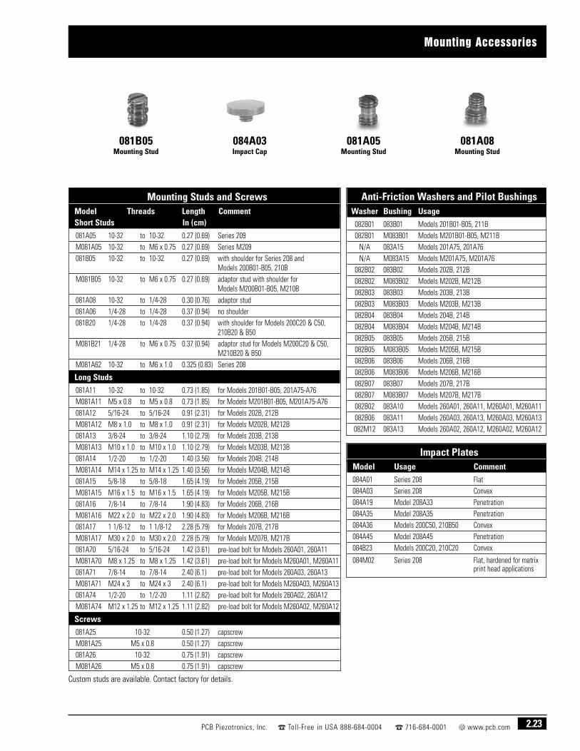
2.23PCB Piezotronics, Inc. Toll-Free in USA 888-684-0004 716-684-0001 www.pcb.com
Mounting Accessories
081B05Mounting Stud
084A03Impact Cap
081A05Mounting Stud
081A08Mounting Stud
Mounting Studs and ScrewsModel Threads Length CommentShort Studs In (cm)
081A05 10-32 to 10-32 0.27 (0.69) Series 209M081A05 10-32 to M6 x 0.75 0.27 (0.69) Series M209081B05 10-32 to 10-32 0.27 (0.69) with shoulder for Series 208 and
Models 200B01-B05, 210BM081B05 10-32 to M6 x 0.75 0.27 (0.69) adaptor stud with shoulder for
Models M200B01-B05, M210B081A08 10-32 to 1/4-28 0.30 (0.76) adaptor stud081A06 1/4-28 to 1/4-28 0.37 (0.94) no shoulder081B20 1/4-28 to 1/4-28 0.37 (0.94) with shoulder for Models 200C20 & C50,
210B20 & B50M081B21 1/4-28 to M6 x 0.75 0.37 (0.94) adaptor stud for Models M200C20 & C50,
M210B20 & B50M081A62 10-32 to M6 x 1.0 0.325 (0.83) Series 208
Long Studs
081A11 10-32 to 10-32 0.73 (1.85) for Models 201B01-B05, 201A75-A76M081A11 M5 x 0.8 to M5 x 0.8 0.73 (1.85) for Models M201B01-B05, M201A75-A76081A12 5/16-24 to 5/16-24 0.91 (2.31) for Models 202B, 212BM081A12 M8 x 1.0 to M8 x 1.0 0.91 (2.31) for Models M202B, M212B081A13 3/8-24 to 3/8-24 1.10 (2.79) for Models 203B, 213BM081A13 M10 x 1.0 to M10 x 1.0 1.10 (2.79) for Models M203B, M213B081A14 1/2-20 to 1/2-20 1.40 (3.56) for Models 204B, 214BM081A14 M14 x 1.25 to M14 x 1.25 1.40 (3.56) for Models M204B, M214B081A15 5/8-18 to 5/8-18 1.65 (4.19) for Models 205B, 215BM081A15 M16 x 1.5 to M16 x 1.5 1.65 (4.19) for Models M205B, M215B081A16 7/8-14 to 7/8-14 1.90 (4.83) for Models 206B, 216BM081A16 M22 x 2.0 to M22 x 2.0 1.90 (4.83) for Models M206B, M216B081A17 1 1/8-12 to 1 1/8-12 2.28 (5.79) for Models 207B, 217BM081A17 M30 x 2.0 to M30 x 2.0 2.28 (5.79) for Models M207B, M217B081A70 5/16-24 to 5/16-24 1.42 (3.61) pre-load bolt for Models 260A01, 260A11M081A70 M8 x 1.25 to M8 x 1.25 1.42 (3.61) pre-load bolt for Models M260A01, M260A11081A71 7/8-14 to 7/8-14 2.40 (6.1) pre-load bolt for Models 260A03, 260A13M081A71 M24 x 3 to M24 x 3 2.40 (6.1) pre-load bolt for Models M260A03, M260A13081A74 1/2-20 to 1/2-20 1.11 (2.82) pre-load bolt for Models 260A02, 260A12M081A74 M12 x 1.25 to M12 x 1.25 1.11 (2.82) pre-load bolt for Models M260A02, M260A12
Screws
081A25 10-32 0.50 (1.27) capscrewM081A25 M5 x 0.8 0.50 (1.27) capscrew081A26 10-32 0.75 (1.91) capscrewM081A26 M5 x 0.8 0.75 (1.91) capscrew
Anti-Friction Washers and Pilot BushingsWasher Bushing Usage
082B01 083B01 Models 201B01-B05, 211B082B01 M083B01 Models M201B01-B05, M211B
N/A 083A15 Models 201A75, 201A76N/A M083A15 Models M201A75, M201A76
082B02 083B02 Models 202B, 212B082B02 M083B02 Models M202B, M212B082B03 083B03 Models 203B, 213B082B03 M083B03 Models M203B, M213B082B04 083B04 Models 204B, 214B082B04 M083B04 Models M204B, M214B082B05 083B05 Models 205B, 215B082B05 M083B05 Models M205B, M215B082B06 083B06 Models 206B, 216B082B06 M083B06 Models M206B, M216B082B07 083B07 Models 207B, 217B082B07 M083B07 Models M207B, M217B082B02 083A10 Models 260A01, 260A11, M260A01, M260A11082B06 083A11 Models 260A03, 260A13, M260A03, M260A13082M12 083A13 Models 260A02, 260A12, M260A02, M260A12
Impact PlatesModel Usage Comment
084A01 Series 208 Flat084A03 Series 208 Convex084A19 Model 208A33 Penetration084A35 Model 208A35 Penetration084A36 Models 200C50, 210B50 Convex084A45 Model 208A45 Penetration084B23 Models 200C20, 210C20 Convex
084M02 Series 208 Flat, hardened for matrixprint head applications
Custom studs are available. Contact factory for details.

Dynamic Force and Strain Sensor Calibration Services
PCB®’s calibration laboratory is accredited by The American Association for LaboratoryAccreditation (A2LA) to ISO 17025 standards. PCB® provides NIST (National Institute ofStandards and Technology) traceable calibration and testing services for all force andstrain sensor products. Calibrations and re-certifications performed by PCB® conform toANSI/NCSL Z540-1-1994 and ISO/IEC 17025-1999 standards.
Each individually calibrated force sensor is supplied with a certificate indicatingcalibrated sensitivity as shown in Figure 13, on the next page. Determining thesensitivity of sensors with operating ranges from 5000 to 100k lb (22k to 450k N) isperformed by placing the force sensor in a hydraulic press stand. In series with thesensor is a load cell reference force standard selected for the operating range of thesensor. Figure 14, on the next page depicts a force sensor calibration press. Referenceload cells are calibrated and certified every six months to verify calibrated value. Ascaled down test stand is used for lower ranged sensors. Miniature, high-sensitivitymodels are calibrated by applying a known light weight mass, letting the signal zero, andthen quickly removing the mass. Output recorded is the sensitivity of the sensor. Chargeoutput and longer time constant sensors are calibrated by statically applying a knownforce and recording output data.
In each calibration procedure, data points are plotted at 20% intervals of the sensor’soperating range. These points are graphically plotted and the best straight line throughzero is drawn.
Should calibrated points fall outside the specified linearity as provided in publishedspecifications, the unit fails calibration and is rejected.
The scope of our accreditation for dynamic force sensors is:
Range Best Uncertainty [1] (±)
0 to 100k lb (0 to 445k N) 1.0% FS
[1] Best Uncertainties represent expanded uncertainties expressed at approximately the 95%confidence level using a coverage factor k = 2.
Calibration of Dynamic Force Sensors
2.24 PCB Piezotronics, Inc. Toll-Free in USA 888-684-0004 716-684-0001 www.pcb.com
Dynamic Force and Strain Sensor Calibration ServicesPCB® Sensor Competitor Sensor
Calibration Code Calibration CodeFCS-1 FCS-0 Calibration of dynamic force and strain sensors (complies with ISO 10012-1 and NIST traceable)
FCS-2 FCS-0 Calibration of dynamic triaxial force sensors (complies with ISO 10012-1 and NIST traceable)
FCS-3 FCS-0 System calibration of dynamic force or strain sensor with electronics.
FCS-4 FCS-0 Calibration of dynamic strain sensor.
FCS-5 FCS-0 Calibration of dynamic force ring where pre-load stud does not shunt forces.
FCS-xx FCS-0 Additional calibration run on dynamic force sensor other than full scale.
FCS-QC N/A Special QC documentation for dynamic force sensors
Other calibration services available; contact factory for more information.

2.25PCB Piezotronics, Inc. Toll-Free in USA 888-684-0004 716-684-0001 www.pcb.com
Dynamic Force and Strain Sensor Calibration Services
Figure 13. Typical Force Sensor Calibration Certificate
Figure 14. Force Calibration Fixture, 5000 to 100k lb

2.26 PCB Piezotronics, Inc. Toll-Free in USA 888-684-0004 716-684-0001 www.pcb.com
Simple, ready-to-use monitoring systems that usepiezoelectric quartz ICP® strain sensors and signal conditioners are ideal for product qualityassurance applications that require the measurement of repetitive cycles. ICP® strain sensors feature high stiffness, sensitivity stability, repeatability, high resolution, extremely long life, and robust packaging forharsh industrial environments.
Proper assembly force is vital to the strength of a formed metal part. An assembly force that
is too low results in poor mechanical strength of the joint. A force that is too high causesexcessive deformation, and can damage or reduce the fatigue life of a component. Processessuch as clinching, circuit board assembly, orbital forming, press-fit, riveting, staking, andother assembly operations may be monitored in-process to determine whether the joint hasbeen properly manufactured.
Strain sensor signals may also be used to protect machinery from excessive forces, trend toolwear, capture process deviations, and document the process to help ensure delivery of highquality parts with zero defects.

Technical Information
3.1PCB Piezotronics, Inc. Toll-Free in USA 888-684-0004 716-684-0001 www.pcb.com
■ Introduction to force sensors
■ Driving long cable lengths
■ Conversions, article reprints, glossary
■ Force sensor application inquiry form
Highlights
Quartz Force Sensors are well-suited for dynamic force measurement applications. Theyare not interchangeable with strain gage load cells used for static force measurements.
Measurements of dynamic oscillating forces, impact or high speed compression/tensionunder varying conditions may require sensors with special capabilities. Fast response,ruggedness, high stiffness, extended range and the ability to also measure quasi-staticforces are standard features associated with PCB® quartz force sensors.
The following information presents some of the design and operating characteristics of PCB® quartz force sensors to help you better understand how they function, which in turn, will help you make better dynamic measurements.
Types of Quartz Force SensorsThis catalog describes two modes of operation for quartz force sensors manufactured byPCB®. ICP® (IEPE, or voltage output type sensors) feature built-in microelectronicamplifiers, which convert the high-impedance electrostatic charge signal from thecrystals into a low-impedance voltage output signal (ICP® is a registered trademark of PCB Group, Inc.). The other type are charge output force sensors, which directly outputa high-impedance electrostatic charge signal.
Sensor ConstructionBoth modes of operation for PCB® force sensors feature similar mechanical construction.Most are designed with thin quartz crystal discs that are “sandwiched” between upperand lower base plates. An elastic, beryllium-copper stud holds the plates together andpre-loads the crystals (pre-loading assures parts are in intimate contact to ensurelinearity and provide the capability for tensile force measurements). This “sensingelement” configuration is then packaged into a rigid, stainless-steel housing and weldedto assure the internal components are sealed against contamination.
Figure 1 illustrates the cross-section of a typical quartz force sensor. This particularsensor is a general purpose Series 208 compression/tension model with built-in electronics.
When force is applied to this sensor, the quartz crystals generate an electrostatic chargethat is proportional to the input force. This charge output is collected on electrodes thatare sandwiched between the crystals. It is then either routed directly to an externalcharge amplifier or converted to a low-impedance voltage signal within the sensor. Boththese modes of operation will be examined in the following sections.
Introduction To Quartz Force Sensors
Figure 1.Compression-Tension-Impact Series 208

3.2 PCB Piezotronics, Inc. Toll-Free in USA 888-684-0004 716-684-0001 www.pcb.com
Introduction To Force Sensors
A charge output piezoelectric force sensor, when stressed, generates an electrostaticcharge from the crystals. For accurate analysis or recording purposes, this high-impedance charge must be routed through a special low-noise cable to an impedanceconverting amplifier such as a laboratory charge amplifier or source follower. Connectionof the sensor directly to a readout device such as an oscilloscope is possible for high-frequency impact indication, but is not suitable for most quantitative forcemeasurements.
The primary function of the charge or voltage amplifier is to convert the high-impedancecharge output to a usable low-impedance voltage signal for analysis or recordingpurposes. Laboratory charge amplifiers provide added versatility for signal normalization,ranging and filtering. PCB®’s electro-static charge amplifiers have additional inputadjustments for quasi-static measurements, static calibration, and drift-free dynamicoperation. Miniature in-line amplifiers are generally of fixed range and frequency.
Quartz charge output force sensors can be used at operating temperatures up to +400 °F (+204 °C).
When considering the use of charge output systems, remember that the output from thecrystals is a pure electrostatic charge. The internal components of the force sensor andthe external electrical connector maintain a very high (typically >1012 ohm) insulationresistance so that the electrostatic charge generated by the crystals does not “leakaway.” Consequently, any connectors, cables or amplifiers used must also have a veryhigh insulation resistance to maintain signal integrity.
Environmental contaminants such as moisture, dirt, oil, or grease can all contribute toreduced insulation, resulting in signal drift and inconsistent results.
The use of special, low- noise cable is required with charge output force sensors. Standard,two-wire or coaxial cable, when flexed, generates an electrostatic charge between theconductors. This is referred to as “triboelectric noise” and cannot be distinguished from thesensor’s crystal electrostatic output. Low-noise cables have a special graphite lubricantbetween the dielectric shield which minimizes the triboelectric effect.
Figure 2 shows a typical charge output sensor system schematic including: sensor, low-noise cable, and charge amplifier.
If the measurement signal must be transmitted over long distances, PCB® recommendsthe use of an in-line charge converter, placed near the force sensor. This minimizes thechance of noise. In-line charge converters can be operated from the same constant-current excitation power source as ICP® force sensors to minimize system cost.Figure 3 shows two typical charge output systems and their components.
Conventional Charge Output Sensors
q = charge signalC1 = sensor capacitanceC2 = cable capacitanceC3 = amplifier input capacitanceCf = amplifier feedback capacitor
Figure 2.Charge Output Sensor System Schematic
Readout Device
Standard Sensor Cable orOutput Cable*
In-line ChargeConverter
Low-noiseSensorCable
ICP® SensorSignal
Conditioner
Charge OutputForce Sensor
OutputCable
Charge OutputForce Sensor
Low-noiseSensor Cable
ChargeAmplifier
OutputCable
Readout DeviceFigure 3.Charge Output Systems
* Low-noise cable is required to maintain conformance.

Introduction To Force Sensors
3.3PCB Piezotronics, Inc. Toll-Free in USA 888-684-0004 716-684-0001 www.pcb.com
ICP® force sensors incorporate a built-in MOSFET microelectronic amplifier. This servesto convert the high-impedance charge output into a low-impedance voltage signal foranalysis or recording. ICP® sensors, powered from a separate constant current source,operate over long ordinary coaxial or ribbon cable without signal degradation. The low-impedance voltage signal is not affected by triboelectric cable noise orenvironmental contaminants.
Power to operate ICP® sensors is generally in the form of a low cost, 24 to 27 VDC, 2 to20 mA constant current supply. Figure 4 schematically illustrates a typical ICP® sensorsystem. PCB® offers a number of AC or battery powered, single or multi-channelpower/signal conditioners, with or without gain capabilities, for use with force sensors(see Signal Conditioners Section of this catalog for available models). In addition, manydata acquisition systems now incorporate constant current power for directly poweringICP® sensors. Because static calibration or quasi-static short-term response lasting up toa few seconds is often required, PCB® also manufactures signal conditioners that provideDC coupling.
Figure 5. summarizes a complete 2-wire ICP® system configuration. In addition to easeof operation, ICP® force sensors offer significant advantages over charge output types.Because of the low-impedance output and solid-state, hermetic construction, ICP® forcesensors are well-suited for continuous, unattended force monitoring in harsh factoryenvironments. Also, ICP® sensor cost-per-channel is substantially lower, since theyoperate through standard, low-cost coaxial cable, and do not require expensive chargeamplifiers.
PolarityThe output voltage polarity of ICP® force sensors is positive for compression andnegative for tension force measurements. ICP® strain sensors have the opposite polarity.The polarity of PCB® charge output force sensors is the opposite: negative forcompression and positive for tension. This is because charge output sensors are usuallyused with external charge amplifiers that exhibit an inverting characteristic. Therefore,the resulting system output polarity of the charge amplifier system is positive forcompression and negative for tension; same as for an ICP® sensor system (reversepolarity sensors are also available).
Why Can Only Dynamic Force be Measured with Piezoelectric Force Sensors?The quartz crystals of a piezoelectric force sensor generate an electrostatic charge onlywhen force is applied to or removed from them. However, even though the electricalinsulation resistance is quite large, the electrostatic charge will eventually leak to zero
through the lowest resistance path. In effect, if you apply a staticforce to a piezoelectric force sensor, the electrostatic chargeoutput initially generated will eventually leak back to zero.
The rate at which the charge leaks back to zero is dependent onthe lowest insulation resistance path in the sensor, cable and theelectrical resistance/capacitance of the amplifier used.
In a charge output force sensor, the leakage rate is usually fixed byvalues of capacitance and resistance in the low-noise cable andexternal charge or source follower amplifier used.
In an ICP® force sensor with built-in electronics, the resistance andcapacitance of the built-in circuitry normally determines theleakage rate.
Continued on next page.
ICP® Low-Impedance Quartz Force Sensors
Figure 4. ICP® Sensor System Schematic
Readout Device
Standard Sensor Cable
or OutputCable*
ICP® Sensor Signal
Conditioner
ICP® ForceSensor
OutputCable
* Low-noise cable is required to maintain conformance.
Figure 5. Typical ICP® Sensor System

3.4 PCB Piezotronics, Inc. Toll-Free in USA 888-684-0004 716-684-0001 www.pcb.com
Introduction To Force Sensors
When a rapid dynamic force is applied to a piezoelectric force sensor, the electrostaticcharge is generated quickly and, with an adequate discharge time constant, does not leakback to zero. However, there is a point at which a slow speed dynamic force becomesquasi-static and the leakage is faster than the rate of the changing force. Where is thepoint at which the force is too slow for the piezoelectric force sensor to make themeasurement? See the next section on Discharge Time Constant for the answer.
Discharge Time Constant (DTC)When leakage of a charge (or voltage) occurs in a resistive capacitive circuit, the leakagefollows an exponential decay. A piezoelectric force sensor system behaves similarly inthat the leakage of the electrostatic charge through the lowest resistance also occurs atan exponential rate. The value of the electrical capacitance of the system (in farads),multiplied by the value of the lowest electrical resistance (in ohm) is called the DischargeTime Constant (in seconds).
DTC is defined as the time required for a sensor or measuring system to discharge itssignal to 37% of the original value from a step change of measurand. This is true of anypiezoelectric sensor, whether the operation be force, pressure or vibration monitoring.The DTC of a system directly relates to the low frequency monitoring capabilities of asystem and, in the case of force monitoring, becomes very important as it is oftendesired to perform quasi-static measurements.
DTC Charge Output SystemIn a charge output system, the sensors do not contain built-in amplifiers, therefore, theDTC is usually determined by the settings on an external charge amplifier. A feedbackresistor working together with a capacitor on the operational amplifier determines thetime constant. PCB®’s laboratory-style charge amplifiers feature short, medium and longtime constant selections. It is assumed that the electrical insulation resistance of theforce sensor and cable connecting to the charge amplifier are larger than that of thefeedback resistor in the charge amplifier; otherwise, drift will occur. Therefore, to assurethis, the force sensor connection point and cable must be kept clean and dry.
Low Frequency Response of ICP® SystemsWith ICP® force sensors, there are two factors which must be considered when makinglow frequency measurements. These are:
1. The discharge time constant characteristic of the ICP® force sensor.2. The discharge time constant of the AC coupling circuit used in the signal
conditioner (if DC coupling is used, only (1) above needs to be considered).It is important that both factors be readily understood by the user to assure accurate lowfrequency measurements.
DTC in ICP® Force SensorsThe DTC is fixed by the components in an ICP® sensor’s internal amplifier. Specificationsfor the ICP® force sensors shown in this catalog list the DTC for each force sensor.
When testing with ICP® sensors, there are two time constants that must be consideredfor low frequency determination, one being that of the sensor which is a fixed value, andthe other being that of the coupling electrical circuit used in the signal conditioner.
When an ICP® sensor is subjected to a step function input, a quantity of charge, q, isproduced proportional to the mechanical input. According to the law of electrostatics,output voltage is ∆V = ∆q/∆C where C is the total capacitance of the sensing element,amplifier, and ranging capacitor.

Introduction To Force Sensors
3.5PCB Piezotronics, Inc. Toll-Free in USA 888-684-0004 716-684-0001 www.pcb.com
This voltage is then amplified by the MOSFET amplifier to determine final sensorsensitivity. After the initial step input, the charge signal decays according to the equation:
q = Qe-t/RC
where:q = instantaneous charge (C) Q = initial quantity of charge (C) R = bias resistor value (ohm) C = total capacitance (F)e = base of natural log (2.718)t = time elapsed since t0 (sec)
The product of R and C represents the DTC (in seconds) of the sensor. Sensor time constantsvary from just a few seconds to >2000 seconds for standard sensors. Special time constantscan be supplied by altering the resistor value, R, in the sensor’s built-in circuitry.
Most readout instruments have a high input impedance of >1 megohm. For thesesystems, the sensor DTC as previously discussed becomes the dominant value and can be used in determining signal discharge rate. However, for signals coupled to low-impedance readout devices, generally <1 megohm, it is necessary to determine the system time constant. This will be explained further in the following section.
Signal Conditioner and Readout Time ConstantsThe external power supply used with an ICP® force sensor may also have a DTCassociated with it. In some ICP® signal conditioners, which feature internal bufferamplifiers or gain amplifiers, the time constant is fixed by various internal componentsand may be shorter, or longer, than the sensor DTC. In signal conditioners withcapacitive-coupled outputs, the DTC is not fixed. In this case, a capacitor used todecouple an ICP® force sensor bias voltage acts with the input impedance of the readoutdevice to create another time constant.
Check the specifications of the signal conditioner to determine if it has a fixed internalDTC, which sets the low frequency response, or if it has a capacitive-coupled output. Ifthe output is capacitive-coupled, the time constant, when fed into the input of thereadout, can be calculated as follows:
DTC = RCwhere:
R = input impedance of readout device (ohm)C = value of coupling capacitor at output of signal conditioner (F)
Note that the output of some capacitive-coupled ICP® sensor power conditioners featurea shunt resistor that overrides the effects of the input resistance of the readout deviceif it is 1 megohm or greater.
AC coupling in the readout device is also an additional type of DTC. Check specificationsfor the power conditioners and readout instrument to be sure they are suitable for yourparticular dynamic measurement. If you have more than one DTC in the system, a timeconstant that is significantly shorter than the others will usually dominate.Determination of the system DTC for oscillating and transient inputs can be calculatedfrom these equations:
Oscillating inputs: DTC = (R1C1) (R2C2)
√ (R1C1)2 + (R2C2)2
Transient inputs: DTC = (R1C1) (R2C2)
(lasting up to 10% of smaller DTC) (R1C1) + (R2C2)
To avoid potential problems, it is recommended to keep the coupling time constant atleast 10 times longer than the sensor time constant. The system discharge time constantdetermines the low frequency response of the system. It is analogous to a first-order
Continued on next page.
Figure 6. Standard DTC Curve
This equation is also graphicallyrepresented in Figure 6.

3.6 PCB Piezotronics, Inc. Toll-Free in USA 888-684-0004 716-684-0001 www.pcb.com
Introduction To Force Sensors
high-pass RC filter. The system’s theoretical low frequency roll-off is illustrated in Figure 7, and can be calculated from the following relationships:
3 dB down: 0.16/DTC = fc10% down: 0.34/DTC = f-10%5% down: 0.5/DTC = f-5%
Long Duration Events and DTCIt is often desired to measure an input pulse lasting a few seconds in duration. This isespecially true with force sensor applications where static calibration or quasi-staticmeasurements take place. Before performing tests of this nature, it is important to DCcouple the entire monitoring system to prevent rapid signal loss. PCB®’s AC/DC modesignal conditioners are designed for such applications.
The general rule of thumb for such measurements is that the output signal loss and timeelapsed over the first 10% of a DTC have an approximate one to one relationship. If asensor has a 500 second DTC, over the first 50 seconds, 10% of the original input signalwill have decayed. For 1% accuracy, data should be taken in the first 1% of the DTC. If8% accuracy is acceptable, the measurement should be taken within 8% of the DTC, andso forth. Figure 8 graphically demonstrates this event.
Left unchanged, the signal will naturally decay toward zero. This will take approximately5 DTC. You will notice that after the original step impulse signal is removed, the outputsignal dips below the base line reference point (t0 +0.01 TC). This negative value is thesame value as has decayed from the original impulse (shown as 1% in Figure 8). Furtherobservation will reveal that the signal, left untouched, will decay upwards toward zerountil equilibrium in the system is observed.
Force Sensor Natural FrequencyUnlike the low frequency response of the sensor, which is determined electricallythrough the DTC = RC equation, the high frequency response is determined by thesensor’s mechanical configuration (unless electrical low-pass filtering has been added).Each force sensor has an upper frequency limit specification which should be observedwhen determining upper linear limits of operation.
InstallationProper installation of quartz force sensors is essential for accurate dynamicmeasurement results. Although rugged PCB® quartz force sensors are forgiving to somedegree, certain basic procedures should be followed.
Since most PCB® force sensors are designed with quartz compression plates to measureforces applied in an axial direction, aligning the sensor and contact surfaces to preventedge loading or bending moments in the sensor will produce better dynamicmeasurement results.
Having parallelism between the sensor and test structure contact surfaces minimizesbending moments and edge loading. Flatness of mounting surfaces will also affect thequality of the measurement. Using a thin layer of lubricant on mounting surfaces duringinstallation creates better contact between sensor and mounting surface.
The mounting surfaces on PCB® force sensors are lapped during their manufacture toensure that they are flat, parallel and smooth. Ring-style force sensors are supplied withanti-friction washers to minimize shear loading of the sensor surface when torquingbetween two surfaces.
Loading to the entire force sensor sensing surface is also important for goodmeasurements. However, this can be difficult if the surface being brought into contactwith the force sensor is flat but not parallel to the sensor mounting surface. In this case,an intermediate curved surface can lessen edge loading effects (See Figure 9).
Figure 7.Low Frequency Characteristic of a First-order, High-pass Filter
Figure 8. Step Function Response
Figure 9.Edge vs. Central Loading

Introduction To Force Sensors
3.7PCB Piezotronics, Inc. Toll-Free in USA 888-684-0004 716-684-0001 www.pcb.com
Series 208 force sensors are supplied with a convex curved impact cap to help spreadthe forces over the entire surface of the force sensor.
One other consideration when mounting force sensors is to minimize unnecessarymechanical high frequency shock loading of the sensors. The high frequency content ofdirect metal-to-metal impacts can often create short duration, high “g” overloads instructures and sensors. This problem can be minimized by using a thin damping layer ofa softer material on the interface surface between the structure and sensor beingimpacted (it should be considered beforehand whether the slight damping of the highfrequency shock is critical to the force measurement requirements). The impact surfaceon Series 200 and the impact caps on Series 208 force sensors are supplied with thinlayers of damping material.
Pre-Loading Force Rings and 3-Component Force SensorsPCB® ring-style 1-component and 3-component force sensors are generally installedbetween two parts of a test structure with the supplied elastic beryllium-copper stud orcustomer-supplied bolt. The stud or bolt holds the structure together, and applies pre-load to the force ring as shown in Figure 10. In the typical installation, shown on the leftside in Figure 10, part of the force between the two structures is shunted through themounting stud. The amount of force shunted may be up to 7% of the total force for theberyllium-copper stud supplied with the sensor, and up to 50% for steel studs. Thistypical installation setup is used by PCB® during standard calibrations.
A non-typical installation is shown on the right side in Figure 10. In this non-typicalinstallation, the stud or bolt used to apply the pre-load does not shunt part of the appliedforce. The plate on top of the sensor has a clearance hole that the stud or bolt passesthrough. In this installation, the stud or bolt is not directly connected to the top plate byits threads, as it is in the typical installation, so it does not shunt any force.
NOTE: If any of the following conditions apply to the pre-loading of the force ring in theapplication, the sensitivity and linearity performance of the sensor will not match thestandard PCB® calibration values.
1. Use of a stud or bolt other than the supplied beryllium-copper stud
2. Use of no stud or bolt
3. Use of an amount of pre-load other than the recommended amount
4. Use of the non-typical installation setup shown below
In these cases, please contact a PCB® application engineer to discuss yourspecial calibration requirements.
PCB® in-house calibration procedure requires the installation of a force ring withberyllium-copper stud, in the typical installation setup above, in series with a NISTtraceable reference sensor. Generally, a pre-load of 20% (full-scale operating range of the force ring) is applied before recording of measurement data. Contact a PCB®
application specialist for proper pre-load requirements. Allow the static component ofthe signal to discharge before calibration.
Three-component force sensors must be pre-loaded to achieve proper operation,particularly for the shear x-, and y-axis. The recommended applied pre-load for three-component force sensors is 10 times their x or y axes measurement range. This pre-loadprovides the sensing crystals with the compressive loading required to achieve an outputin response to shear direction input forces. As with force rings, the sensitivity achievedfrom a 3-component force sensor is dependent upon the applied pre-load and theelasticity characteristics of the mounting bolt or stud used. If the unit is to be installedwith a stud or bolt other than the supplied elastic, beryllium-copper stud, a calibrationusing the actual mounting hardware must be preformed. Errors in sensitivity of up to50% can result by utilizing studs or bolts of different materials.
Typical Installation Non-Typical Installation
Figure 10. Force Ring Sensor Installations
F F

3.8 PCB Piezotronics, Inc. Toll-Free in USA 888-684-0004 716-684-0001 www.pcb.com
Introduction To Force Sensors
Typical Piezoelectric System OutputThe output characteristic of piezoelectric sensors is that of an AC coupled system, whererepetitive signals will decay until there is an equal area above and below the originalbase line. As magnitude levels of the monitored event fluctuate, the output will remainstabilized around the base line with the positive and negative areas of the curveremaining equal. Figure 11 represents an AC signal following this curve (output fromsensors operating in DC mode following this same pattern, but over an extended timeframe associated with sensor time constant values).
Example: Assuming a 0 to 3 volt output signal is generated from an AC coupled force applicationwith a one second steady-state pulse rate and one second between pulses. The frequency remainsconstant, but the signal quickly decays negatively until the signal centers around the original baseline (where area A = area B). Peak-to-peak output remains the same.
Repetitive Pulse ApplicationsIn many force monitoring applications, it is desired to monitor a series of zero-to-peakrepetitive pulses that may occur within a short time interval of one another. This outputsignal is often referred to as a “pulse train”. As has been previously discussed, the ACcoupled output signal from piezoelectric sensors will decay towards an equilibriumstate, making it look like the positive force is decreasing. In this scenario, it would bedifficult to accurately monitor a continuous zero-to-peak output signal such as thoseassociated with stamping or pill press applications. With the use of special ICP® sensorsignal conditioning equipment it becomes possible to position an output signal positivegoing above a ground-based zero. Operating in drift-free AC mode, PCB®’s Model 484B02or a Model 410A01 ICP® sensor signal conditioner provides the constant current voltageexcitation to ICP® force sensors and has a zero-based clamping circuit that electronicallyresets each pulse to zero. As outlined in Figure 12, this special circuitry prevents theoutput from drifting negatively, and provides a continuous, positive polarity signal.
Figure 11. Repetitive Pulse, AC Signal
Figure 12. Positive Polarity, Zero-based AC Output

Driving Long Cable Lengths
3.9PCB Piezotronics, Inc. Toll-Free in USA 888-684-0004 716-684-0001 www.pcb.com
Operation over long cables may effect frequency response and introduce noise and distortion when an insufficient current is available to drive cable capacitance.
Unlike charge output systems, where the system noise is a function of cable length, ICP®
sensors provide a high-voltage, low-impedance output well-suited for driving long cablesthrough harsh environments. While there is virtually no increase in noise with ICP®
sensors, the capacitive loading of the cable may distort or filter higher frequency signalsdepending on the supply current and the output impedance of the sensor.
Generally, this signal distortion is not a problem with lower frequency testing within arange up to 10k Hz. However, for higher frequency vibration, shock, or transient testingover cables longer than 100 ft (30 m), the possibility of signal distortion exists.
The maximum frequency that can be transmitted over a given cable length is a functionof both the cable capacitance and the ratio of the peak signal voltage to the currentavailable from the signal conditioner according to:
fmax = 109
2πCV / (Ic-1)
where, fmax = maximum frequency (hertz)C = cable capacitance (picofarads)V = maximum peak output from sensor (volts)Ic = constant current from signal conditioner (mA)109 = scaling factor to equate units
Note that in the equation, 1 mA is subtracted from the total current supplied to thesensor (Ic). This is done to compensate for powering the internal electronics. Somespecialty sensor electronics may consume more or less current. Contact themanufacturer to determine the correct supply current. When driving long cables, theequation above shows that as the length of cable, peak voltage output or maximumfrequency of interest increases, a greater constant current will be required to drive thesignal.
The nomograph on page 1.91 provides a simple, graphical method for obtaining theexpected maximum frequency capability of an ICP® measurement system. The maximumpeak signal voltage amplitude, cable capacitance, and supplied constant current must beknown or presumed.
For example, when running a 100 ft (30 m) cable with a capacitance of 30 pF/ft (98 pF/m),the total capacitance is 3000 pF. This value can be found along the diagonal cablecapacitance lines. Assuming the sensor operates at a maximum output range of 5 voltsand the constant current signal conditioner is set at 2 mA, the ratio on the vertical axiscan be calculated to equal 5. The intersection of the total cable capacitance and thisratio result in a maximum frequency of approximately 10.2k Hz.
Continued on next page.
Cable Driving Considerations and Constant Current Level
Readout Device
ExtensionCable
CableCoupler
Short SensorCable Output Cable
ICP®
Force SensorICP® Sensor
SignalConditioner

3.10 PCB Piezotronics, Inc. Toll-Free in USA 888-684-0004 716-684-0001 www.pcb.com
Driving Long Cable Lengths
The nomograph does not indicate whether the frequency amplitude response at a pointis flat, rising, or falling. For precautionary reasons, it is good general practice to increasethe constant current (if possible) to the sensor (within its maximum limit) so that thefrequency determined from the nomograph is approximately 1.5 to 2 times greater thanthe maximum frequency of interest.
Note that higher current levels will deplete battery powered signal conditioners at afaster rate. Also, any current not used by the cable goes directly to power the internalelectronics and will create heat. This may cause the sensor to exceed its maximumtemperature specification. For this reason, do not supply excessive current over shortcable runs or when testing at elevated temperatures.
Experimentally Testing Long CablesTo more accurately determine the effect of long cables, it is recommended toexperimentally determine the high frequency electrical characteristics.
The method illustrated below involves connecting the output from a standard signalgenerator into a unity gain, low-output impedance (<5 ohm) instrumentation amplifier inseries with the ICP® sensor. The extremely low output impedance is required to minimizethe resistance change when the signal generator/amplifier is removed from the system.
In order to check the frequency/amplitude response of this system, set the signalgenerator to supply the maximum amplitude of the expected measurement signal.Observe the ratio of the amplitude from the generator to that shown on the scope. If theratio is 1:1, the system is adequate for your test. If necessary, be certain to factor in anygain in the signal conditioner or scope. If the output signal is increasing (+25% forexample), add series resistance to attenuate the signal. Use of a variable 100 ohmresistor will help set the correct resistance more conveniently. Note that this is the onlycondition that requires the addition of resistance. If the signal is decreasing (-25% forexample), the constant current level must be increased or the cable capacitance reduced.
It may be necessary to physically install the cable during cable testing to reflect the actualconditions encountered during data acquisition. This will compensate for potentialinductive cable effects that are partially a function of the geometry of the cable route.
Readout Device
LongExtension
Cable
Model 073A
VariableResistor
Model401A04Sensor
Simulator
SignalGenerator
Short SensorCable
Output Cable
ICP®
SensorSignal
Conditioner

Driving Long Cable Lengths
3.11PCB Piezotronics, Inc. Toll-Free in USA 888-684-0004 716-684-0001 www.pcb.com
VIc - 1
(Ratio of MaximumOutput Voltage fromSensor to AvailableConstant Current)
Frequency (Hz)
fmax = 109
2πCV / (Ic-1)
fmax = maximum frequency (Hz)C = cable capacitance (pF)V = maximum output voltage from sensor (volts)Ic = constant current from power unit (mA)109 = scale factor to equate units
Cable Driving Nomograph

3.12 PCB Piezotronics, Inc. Toll-Free in USA 888-684-0004 716-684-0001 www.pcb.com
Voltage sensitivity of a chargeoutput piezoelectric sensor:
V =
V = voltage sensitivity
q = charge sensitivity
C = capacitance of sensor
Voltage sensitivity of a chargeoutput piezoelectric sensorwith source follower:
V =
C1 = capacitance of sensor
C2 = capacitance of interconnecting cable
C3 = input capacitance of unity gain source follower
Time constant for a first-order,high-pass filter:
t = RC
R = resistance in ohmC = capacitance in faradst = time constant in seconds
Lower corner frequency (-3 dB) for an RC time constant:
fc =
fc = frequency at which signal is attenuated by -3 dB
Lower -5% frequency point foran RC time constant:
f-5% =
f-5% = frequency at which signal is attenuated by 5%
Approximate upper +5%frequency point for single-degree-of-freedommechanical system:
f+5%=
f+5%= frequency at which signal is amplified by 5%
fr = natural (resonant) frequency
Approximating two timeconstants in series foroscillating signals:
(R1C1) (R2C2)
√ (R1C1)2 + (R2C2)2
Approximating two timeconstants in series fortransient inputs lasting up to 10% of the smaller timeconstant value:
(R1C1) (R2C2)(R1C1) + (R2C2)
Rise time of a piezoelectricsensor:
tr =
tr = rise time
fr = natural (resonant) frequency of the sensor
Acceleration:
=
Temperature:
=
Weight:
=
=
=
=
=
Conversion and Useful Formulas
qC
fr5
12 fr
msec2
g9.8
°C(°F-32) 5
9
gmlb
453.59
gmoz
28.35
1 kg 2.204 lb
1 lb 4.448 N
1000 lb 4.448k N
qC1+C2+C3
12 π RC
32 π RC

To order copies of the following articles,simply request the "AR" number precedingeach article; write or call PCB® toll-free at888-684-0004.
AR-1Application of Integrated-Circuits to PiezoelectricTransducers, Paper P4-2PHYMID 67ICP® Transducer - basic operation &application. Cornell Aeronautical Lab,Robert Lally, 1967.
AR-2ICP® ConceptIntegrated-Circuit Piezoelectric. Lowimpedance, voltage mode system,PCB, 1967.
AR-4Guide to ICP®
InstrumentationVoltage vs. charge systems. Effect ofcoupling & time constant on response.Powering ICP® system, Robert Lally, 1971
AR-9Testing the Behavior ofStructuresRigid body, structural, and acousticmodes of behavior testing, RobertLally, 1978.
AR-10Understanding VibrationMeasurementsForce sensor 208A03/modal analysisof cantilever beam, George Lang, 1978.
AR-18Introduction toPiezoelectric SensorsBasic accelerometer, pressure, andforce sensor design considerations &typical applications, Jim Lally, 1985.
AR-19Calibration of PiezoSensorsCalibration Systems for dynamicpressure sensors, force sensors and accelerometers with typicalcalibration results, Jim Lally, 1985.
AR-35Frequency ResponseConsiderations forPiezoelectric Sensorsand Related Inst.Time constant and AC coupling or DC coupling effects on frequency response. Time constant vs. shock pulseinput duration, Ray Limburg,1988.
AR-38Basics of PiezoelectricSensorsICP® sensor features. Upright, invertedcompression, and shear mode, RoyMaines, 1989.
AR-84Impact and Drop Testingwith ICP® Force SensorsBob Metz, Crash Test TechnlogyInternational, November 2006.
AR-85Automotive ComponentDurability Testing UsingPiezoelectronics ForceSensorsBob Metz, Crash Test TechnlogyInternational, May 2006.
Article Reprints
3.13PCB Piezotronics, Inc. Toll-Free in USA 888-684-0004 716-684-0001 www.pcb.com

3.14 PCB Piezotronics, Inc. Toll-Free in USA 888-684-0004 716-684-0001 www.pcb.com
Reprinted with permission from ApplicationNote: AN 243-1, “Effective MachineryMeasurements Using Dynamic SignalAnalyzers,” Hewlett-Packard Company,1991. Editing and additions performed byPCB Piezotronics, Depew, NY, 1998.
Acceleration — The time rate of change of velocity. Typicalunits are ft/s2, meters/s2, and G’s (1G =32.17 ft/s2 = 9.81 m/s2). Accelerationmeasurements are usually made withaccelerometers.
Accelerometer — Transducer whose output is directlyproportional to acceleration. Most commonlyuse piezoelectric crystals to produce output.
Aliasing — A phenomenon which can occur whenever asignal is not sampled at greater than twicethe maximum bandwidth of the signal.Causes high frequency signals to appear atlow frequencies. Aliasing is minimized byfiltering the signal to a bandwidth less than fithe sample rate. When the signal starts at 0Hz (baseband signals), bandwidth can beexchanged to maximum frequency in thedefinition above.
Alignment — A condition whereby the axes of machinecomponents are either coincident, parallel,or perpendicular, according to designrequirements.
Amplification Factor(Synchronous) — A measure of the susceptibility of a rotor tovibration amplitude when rotational speed isequal to the rotor natural frequency (impliesa flexible rotor). For imbalance typeexcitation, synchronous amplification factoris calculated by dividing the amplitude valueat the resonant peak by the amplitude valueat a speed well above resonance (asdetermined from a plot of synchronousresponse vs. rpm).
Amplitude — The magnitude of dynamic motion orvibration. Amplitude is expressed in terms ofpeak-to-peak, zero-to-peak, or rms. For puresine waves only, these are related asfollows: rms = 0.707 times zero-to-peak;peak-to-peak = 2 times zero-to-peak. DSAsgenerally read rms for spectral components,and peak for time domain components.
Anti-aliasing Filter — Most commonly a low-pass filter designed tofilter out frequencies higher than 1/2 thesample rate in order to minimize aliasing.
Anti-friction Bearing — See Rolling Element Bearing.
Asymmetrical Support — Rotor support system that does not provideuniform restraint in all radial directions. Thisis typical for most heavy industrial machinerywhere stiffness in one plane may besubstantially different than stiffness in theperpendicular plane. Occurs in bearings bydesign, or from preloads such as gravity ormisalignment.
Asynchronous — Vibration components that are not related torotating speed (also referred to asnonsynchronous).
Attitude Angle (Steady-State) — The angle between the direction of steady-state preload through the bearing centerline,and a line drawn between the shaftcenterline and the bearing centerline.(Applies to fluid-film bearings.)
Auto Spectrum (Power Spectrum) — DSA spectrum display whose magnituderepresents the power at each frequency, andwhich has no phase.
Averaging — In a DSA, digitally averaging severalmeasurements to improve accuracy or toreduce the level of asynchronouscomponents. Refer to definitions of rms,time, and peak-hold averaging.
Axial — In the same direction as the shaft centerline.
Axial Position — The average position, or change in position,of a rotor in the axial direction with respectto some fixed reference position. Ideally thereference is a known position within thethrust bearing axial clearance or float zone,and the measurement is made with adisplacement transducer observing thethrust collar.
Balancing Resonance Speed(s) — A rotative speed that corresponds to anatural resonance frequency.
Balanced Condition — For rotating machinery, a condition where theshaft geometric centerline coincides with themass centerline.
Balancing — A procedure for adjusting the radial massdistribution of a rotor so that the masscenterline approaches the rotor geometriccenterline.
Band-Pass Filter — A filter with a single transmission bandextending from lower to upper cutofffrequencies. The width of the band isnormally determined by the separation offrequencies at which amplitude is attenuatedby 3 dB (a factor 0.707 ).
Bandwidth — The distance between frequency limits atwhich a band-pass filter attenuates thesignal by 3 dB. In a DSA, the measurementbandwidth is equal to [(frequencyspan)/(number of filters) x (window factor)].Window factors are: 1 for uniform, 1.5 forHanning, and 3.4 for flat top (P301) and 3.6for flat top (P401). See flat top for moreinformation.
Baseline Spectrum — A vibration spectrum taken when a machineis in good operating condition; used as areference for monitoring and analysis.
Blade Passing Frequency — A potential vibration frequency on any bladedmachine (turbine, axial compressor, fan, etc.).It is represented by the number of bladestimes shaft-rotating frequency.
Block Size — The number of samples used in a DSA tocompute the Fast Fourier Transform. Also thenumber of samples in a DSA time display.Most DSAs use a block size of 1024. Smallerblock size reduces frequency resolution.
Bode — Rectangular coordinate plot of 1x componentamplitude and phase (relative to a keyphasor)vs. running speed.
BPFO, BPFI — Common abbreviations for ball pass frequencyof defects on outer and inner bearing races,respectively.
Bow — A shaft condition such that the geometriccenterline of the shaft is not straight.
Glossary of Terms

Brinneling (False) — Impressions made by bearing rollingelements on the bearing race; typicallycaused by external vibration when the shaftis stationary.
Calibration — A test during which known values of themeasured variable are applied to thetransducer or readout instrument, and outputreadings varied or adjusted.
Campbell Diagram — A mathematically constructed diagram usedto check for coincidence of vibration sources(i.e. 1 x imbalance, 2 x misalignment) withrotor natural resonances. The form of thediagram is like a spectral map (frequencyversus rpm), but the amplitude is representedby a rectangular plot, the larger theamplitude the larger the rectangle. Alsoknown as an interference diagram.
Cascade Plot — See Spectral Map.
Cavitation — A condition which can occur in liquid-handling machinery (e.g. centrifugal pumps)where a system pressure decrease in thesuction line and pump inlet lowers fluidpressure and vaporization occurs. The resultis mixed flow which may produce vibration.
Center Frequency — For a bandpass filter, the center of thetransmission band, measured in a linear scale.
Charge Amplifier — Amplifier used to convert accelerometeroutput impedance from high to low, makingcalibration much less dependent on cablecapacitance.
Coherence — Measures how much of the output signal isdependent on the input signal in a linear andtime-invariant way. It is an effective meansof determining the similarity of vibration attwo locations, giving insight into thepossibility of cause and effect relationships.
Constant Bandwidth Filter — A band-pass filter whose bandwidth isindependent of center frequency. The filterssimulated digitally by the FFT in a DSA areconstant bandwidth.
Constant PercentageBandwidth — A band-pass filter whose bandwidth is aconstant percentage of center frequency. 1/3octave filters, including those synthesized inDSAs, are constant percentage bandwidth.
Critical Machinery — Machines which are critical to a major partof the plant process. These machines areusually unspared.
Critical Speeds — In general, any rotating speed which isassociated with high vibration amplitude.Often, the rotor speeds which correspond tonatural frequencies of the system.
Critical Speed Map — A rectangular plot of system naturalfrequency (y-axis) versus bearing or supportstiffness (x-axis).
Cross Axis Sensitivity — A measure of off-axis response of velocityand acceleration transducers.
Cycle — One complete sequence of values of aperiodic quantity.
Damping — The quality of a mechanical system thatrestrains the amplitude of motion with eachsuccessive cycle. Damping of shaft motion isprovided by oil in bearings, seals, etc. Thedamping process converts mechanicalenergy to other forms, usually heat.
Damping, Critical — The smallest amount of damping required toreturn the system to its equilibrium positionwithout oscillation.
Decibels (dB) — A logarithmic representation of amplituderatio, defined as 10 times the base tenlogarithm of the ratio of the measured powerto a reference. dBV readings, for example,are referenced to 1 volt rms. dB amplitudescales are required to display the fulldynamic range of a DSA.
Degrees of Freedom — A phrase used in mechanical vibration todescribe the complexity of the system. Thenumber of degrees of freedom is the numberof independent variables describing the stateof a vibrating system.
Digital Filter — A filter which acts on the data after it hasbeen sampled and digitized. Often used inDSAs to provide anti-aliasing protectionbefore internal re-sampling.
Differentiation — Representation in terms of time rate ofchange. For example, differentiating velocityyields acceleration. In a DSA, differentiationis performed by multiplication by jw in thefrequency domain, where w is frequencymultiplied by 2p. (Differentiation can also beused to convert displacement to velocity.)
Discrete Fourier Transform — A procedure for calculating discretefrequency components (filters or lines) fromsampled time data. Since the frequencydomain result is complex (i.e., real andimaginary components), the number offrequency points is equal to half the numberof time samples (for a real FFT). When usingzoom analysis, the FFT uses complex timedata and then the number of frequency linesis equal to the number of time samples.
Displacement — The change in distance or position of anobject relative to a reference.
Displacement Transducer — A transducer whose output is proportional tothe distance between it and the measuredobject (usually the shaft).
DSA — See Dynamic Signal Analyzer.
Dual Probe — A transducer set consisting of displacementand velocity transducers. Combinesmeasurement of shaft motion relative to thedisplacement transducer with velocity of thedisplacement transducer to produce absolutemotion of the shaft.
Dual Voting — Concept where two independent inputs arerequired before action (usually machineshutdown) is taken. Most often used withaxial position measurements, where failureof a single transducer might lead to anunnecessary shutdown.
Dynamic Motion — Vibratory motion of a rotor system caused bymechanisms that are active only when therotor is turning at speeds above slow rollspeed.
Glossary Of Terms
3.15PCB Piezotronics, Inc. Toll-Free in USA 888-684-0004 716-684-0001 www.pcb.com

3.16 PCB Piezotronics, Inc. Toll-Free in USA 888-684-0004 716-684-0001 www.pcb.com
Dynamic Signal Analyzer(DSA) — Vibration analyzer that uses digital signalprocessing and the Fast Fourier Transform todisplay vibration frequency components.DSAs also display the time domain andphase spectrum, and can usually beinterfaced to a computer.
Eccentricity, Mechanical — The variation of the outer diameter of a shaftsurface when referenced to the truegeometric centerline of the shaft. Out-of-roundness.
Eccentricity Ratio — The vector difference between the bearingcenterline and the average steady-statejournal centerline.
Eddy Current — Electrical current which is generated (anddissipated) in a conductive material in thepresence of an electromagnetic field.
Electrical Runout — An error signal that occurs in eddy currentdisplacement measurements when shaftsurface conductivity varies.
Engineering Units — In a DSA, refers to units that are calibratedby the user (e.g., in/s, g’s).
External Sampling — In a DSA, refers to control of data samplingby a multiplied tachometer signal. Provides astationary display of rpm-related peaks withchanging speed.
Fast Fourier Transform (FFT) — A computer (or microprocessor) procedure forcalculating discrete frequency componentsfrom sampled time data. A special case ofthe Discrete Fourier Transform, DFT, wherethe number of samples is constrained to apower of 2 for speed.
Filter — Electronic circuitry designed to pass or rejecta specific frequency band.
Finite Element Modeling — A computer aided design technique forpredicting the dynamic behavior of amechanical system prior to construction.Modeling can be used, for example, topredict the natural frequencies of a flexiblerotor.
Flat Top Filter — FFT window function which provides the bestamplitude accuracy for measuring discretefrequency components. Note: there areseveral different flat top windows. The HPproprietary P401 is the “best” flat topwindow. P301 is the most common.
Fluid-Film Bearing — A bearing which supports the shaft on a thinfilm of oil. The fluid-film layer may begenerated by journal rotation (hydrodynamicbearing), or by externally applied pressure(hydrostatic bearing).
Forced Vibration — The oscillation of a system under the actionof a forcing function. Typically forcedvibration occurs at the frequency of theexciting force.
Free Vibration — Vibration of a mechanical system followingan initial force - typically at one or morenatural frequencies.
Frequency — The repetition rate of a periodic event,usually expressed in cycles per second (Hz),revolutions per minute (rpm), or multiples ofa rotational speed (orders). Compare toorders that are commonly referred to as 1xfor rotational speed, 2x for twice rotationalspeed, etc.
Frequency Response Function — The amplitude and phase responsecharacteristics of a system.
G — The value of acceleration produced by theforce of gravity.
Gear Mesh Frequency — A potential vibration frequency on anymachine that contains gears; equal to thenumber of teeth multiplied by the rotationalfrequency of the gear.
Hanning Window — FFT window function that normally providesbetter frequency resolution than the flat topwindow, but with reduced amplitudeaccuracy.
Harmonic — Frequency component at a frequency that isan integer multiple of the fundamentalfrequency.
Heavy Spot — The angular location of the imbalance vectorat a specific lateral location on a shaft. Theheavy spot typically does not change withrotational speed.
Hertz (Hz) — The unit of frequency represented by cyclesper second.
High Spot — The angular location on the shaft directlyunder the vibration transducer at the point ofclosest proximity. The high spot can movewith changes in shaft dynamics (e.g., fromchanges in speed).
High-Pass Filter — A filter with a transmission band starting ata lower cutoff frequency and extending to(theoretically) infinite frequency.
Hysteresis — Non-uniqueness in the relationship betweentwo variables as a parameter increases ordecreases. Also called deadband, or thatportion of a system’s response where achange in input does not produce a change inoutput.
Imbalance — Unequal radial weight distribution on a rotorsystem; a shaft condition such that the massand shaft geometric center lines do notcoincide.
Impact Test — Response test where the broad frequencyrange produced by an impact is used as thestimulus. Sometimes referred to as a bumptest. See impulse response for moreinformation.
Impedance, Mechanical — The mechanical properties of a machinesystem (mass, stiffness, damping) thatdetermine the response to periodic forcingfunctions.
Impulse Response — The response of a system to an impulse asinput signal. The output then produces theimpulse response that is the time domainequivalent to the Frequency ResponseFunction, FRF.
Influence Coefficients — Mathematical coefficients that describe theinfluence of system loading on systemdeflection.
Glossary Of Terms

Integration — A process producing a result that, whendifferentiated, yields the original quantity.Integration of acceleration, for example,yields velocity. Integration is performed in aDSA by dividing the frequency lines by jw,where w is frequency multiplied by 2p.(Integration is also used to convert velocity todisplacement.)
Journal — Specific portions of the shaft surface fromwhich rotor applied loads are transmitted tobearing supports.
Keyphasor — A signal used in rotating machinerymeasurements, generated by a transducerobserving a once-per-revolution event. Thekeyphasor signal is used in phasemeasurements for analysis and balancing.(Keyphasor is a Bently Nevada trade name.)
Lateral Location — The definition of various points along theshaft axis of rotation.
Lateral Vibration — See Radial Vibration.
Leakage — In DSAs, a result of finite time record lengththat results in smearing of frequencycomponents. Its effects are greatly reducedby the use of weighted time functions suchas Flat top or Hanning windows.
Linearity — The response characteristics of a linearsystem remain constant with input leveland/or excitation signal type. That is, if theresponse to input a is k·a, and the responseto input b is k·b, then the response of a linearsystem to input (a + b) will be (k·a + k·b),independent of the function k. An example ofa non-linear system is one whose responseis limited by mechanical stop, such as occurswhen a bearing mount is loose.
Lines — Common term used to describe the filters ofa DSA produced by the FFT (e.g., 400 lineanalyzer).
Linear Averaging — See Time Averaging.
Low-pass Filter — A filter whose transmission band extendsfrom dc to an upper cutoff frequency.
Mechanical Runout — An error in measuring the position of theshaft centerline with a displacement probethat is caused by out-of-roundness andsurface imperfections.
Micrometer (MICRON) — One millionth (.000001) of a meter. (1 micron= 1 x E-6 meters @ 0.04 mils.)
MIL — One thousandth (0.001) of an inch. (1 mil =25.4 microns)
Modal Analysis — The process of breaking complex vibrationinto its component modes of vibration, verymuch like frequency domain analysis breaksvibration down to component frequencies.
Mode Shape — The resultant deflected shape of a rotor at aspecific rotational speed to an appliedforcing function. A three-dimensionalpresentation of rotor lateral deflection alongthe shaft axis.
Modulation, Amplitude (AM) — The process where the amplitude of a signalis varied as a function of the instantaneousvalue of a another signal. The first signal iscalled the carrier, and the second signal iscalled the modulating signal. Amplitudemodulation always produces a component atthe carrier frequency, with components(sidebands) at the frequency of the carrierfrequency plus minus the modulating signal.
Modulation, Frequency (FM) — The process where the frequency of thecarrier is determined by the amplitude of themodulating signal. Frequency modulationproduces a component at the carrierfrequency, with adjacent components(sidebands) at frequencies around the carrierfrequency related to the modulating signal.The carrier and sidebands are described byBessel functions.
Natural Frequency — The frequency of free vibration of a system.The frequency at which an undamped systemwith a single degree of freedom will oscillateupon momentary displacement from its restposition.
Nodal Point — A point of minimum shaft deflection in aspecific mode shape. May readily changelocation along the shaft axis due to changesin residual imbalance or other forcingfunction, or change in restraint such asincreased bearing clearance.
Noise — Any component of a transducer output signalthat does not represent the variable intendedto be measured.
Nyquist Criterion — Requirement that a sampled system needs tobe sampled at a frequency greater thantwice the bandwidth of the signal to besampled.
Nyquist Plot — A plot of real versus imaginary spectralcomponents that is often used in servoanalysis. Should not be confused with apolar plot of amplitude and phase of 1xvibration.
Octave — The interval between two frequencies with aratio of 2 to 1.
Oil Whirl/Whip — An unstable free vibration whereby a fluid-film bearing has insufficient unit loading.Under this condition, the shaft centerlinedynamic motion is usually circular in thedirection of rotation. Oil whirl occurs at theoil flow velocity within the bearing, usually40 to 49% of shaft speed. Oil whip occurswhen the whirl frequency coincides with(and becomes locked to) a shaft resonantfrequency. (Oil whirl and whip can occur inany case where fluid is between twocylindrical surfaces.)
Orbit — The path of the shaft centerline motion duringrotation. The orbit is observed with anoscilloscope connected to x and y-axisdisplacement transducers. Some dual-channelDSAs also have the ability to display orbits.
Oscillator-demodulator — A signal conditioning device that sends aradio frequency signal to an eddy-currentdisplacement probe, demodulates the probeoutput, and provides output signalsproportional to both the average anddynamic gap distances. (Also referred to asProximitor, a Bently Nevada trade name.)
Glossary Of Terms
3.17PCB Piezotronics, Inc. Toll-Free in USA 888-684-0004 716-684-0001 www.pcb.com

3.18 PCB Piezotronics, Inc. Toll-Free in USA 888-684-0004 716-684-0001 www.pcb.com
Peak Hold — In a DSA, a type of averaging that holds thepeak signal level for each frequencycomponent.
Period — The time required for a complete oscillationor for a single cycle of events. The reciprocalof frequency.
Phase — A measurement of the timing relationshipbetween two signals, or between a specificvibration event and a keyphasor pulse. Phaseis often measured as a function of frequency.
Piezoelectric — Any material which provides a conversionbetween mechanical and electrical energy.For a piezoelectric crystal, if mechanicalstresses are applied on two opposite faces,electrical charges appear on some other pairof faces.
Polar Plot — Polar coordinate representation of the locusof the 1x vector at a specific lateral shaftlocation with the shaft rotational speed as aparameter.
Power Spectrum — See Auto Spectrum.
Pre-load, Bearing — The dimensionless quantity that is typicallyexpressed as a number from zero to onewhere a preload of zero indicates no bearingload upon the shaft, and one indicates themaximum preload (i.e., line contact betweenshaft and bearing).
Pre-load, External — Any of several mechanisms that canexternally load a bearing. This includes “soft”preloads such as process fluids or gravitationalforces as well as “hard” preloads from gearcontact forces, misalignment, rubs, etc.
Proximitor — See Oscillator/Demodulator.
Radial — Direction perpendicular to the shaft centerline.
Radial Position — The average location, relative to the radialbearing centerline, of the shaft dynamicmotion.
Radial Vibration — Shaft dynamic motion or casing vibrationwhich is in a direction perpendicular to theshaft centerline.
Real-time Analyzer — See Dynamic Signal Analyzer.
Real-time Rate — For a DSA, the broadest frequency span atwhich data is sampled continuously. Real-time rate is mostly dependent on FFTprocessing speed. If the definition of real-time rate is “not miss any data”, the real-time rate will be window dependent. Thereal-time rate will decrease when using anyother window than uniform.
Rectangular Window — See Uniform Window.
Relative Motion — Vibration measured relative to a chosenreference. Displacement transducers generallymeasure shaft motion relative to thetransducer mounting.
Repeatability — The ability of a transducer or readoutinstrument to reproduce readings when thesame input is applied repeatedly.
Resolution — The smallest change in stimulus that willproduce a detectable change in theinstrument output.
Resonance — The condition of vibration amplitude andphase change response caused by acorresponding system sensitivity to aparticular forcing frequency. A resonance istypically identified by a substantialamplitude increase, and related phase shift.
Rolling Element Bearing — Bearing whose low friction qualities derivefrom rolling elements (balls or rollers), withlittle lubrication.
Root Mean Square (rms) — Square root of the arithmetical average of aset of squared instantaneous values. DSAsperform rms averaging digitally onsuccessive vibration spectra, frequency lineby frequency line.
Rotor, Flexible — A rotor which operates close enough to, orbeyond its first bending critical speed fordynamic effects to influence rotordeformations. Rotors which cannot beclassified as rigid rotors are considered to beflexible rotors.
Rotor, Rigid — A rotor which operates substantially belowits first bending critical speed. A rigid rotorcan be brought into, and will remain in, astate of satisfactory balance at all operatingspeeds when balanced on any two arbitrarilyselected correction planes.
Runout Compensation — Electronic correction of a transducer outputsignal for the error resulting from slow rollrunout.
Seismic — Refers to an inertially referencedmeasurement or a measurement relative tofree space.
Seismic Transducer — A transducer that is mounted on the case or housing of a machine and measurescasing vibration relative to free space.Accelerometers and velocity transducers areseismic.
Signal Conditioner — A device placed between a signal source anda readout instrument to change the signaland/or bandwidth. Examples: attenuators,preamplifiers, charge amplifiers, filters.
Signature — Term usually applied to the vibrationfrequency spectrum which is distinctive andspecial to a machine or component, systemor subsystem at a specific point in time,under specific machine operating conditions,etc. Used for historical comparison ofmechanical condition over the operating lifeof the machine.
Slow Roll Speed — Low rotative speed at which dynamic motioneffects from forces such as imbalance arenegligible.
Spectral Map — A three-dimensional plot of the vibrationamplitude spectrum versus another variable,usually time or rpm.
Spectrum Analyzer — An instrument which displays the frequencyspectrum of an input signal.
Stiffness —The spring-like quality of mechanical andhydraulic elements to elasticity deform underload.
Glossary Of Terms
Strain — The physical deformation, deflection, orchange in length resulting from stress (forceper unit area).
Subharmonic — Sinusoidal quantity of a frequency that is anintegral submultiple of a fundamentalfrequency.
Subsynchronous — Component(s) of a vibration signal which hasa frequency less than shaft rotativefrequency.
Synchronous Sampling — In a DSA, it refers to the control of theeffective sampling rate of data; whichincludes the processes of external samplingand computed resampling used in ordertracking.
Time Averaging — In a DSA, averaging of time records thatresults in reduction of asynchronouscomponents with reference to the trigger.
Time Record — In a DSA, the sampled time data converted tothe frequency domain by the FFT. Most DSAsuse a time record of 1024 samples.
Torsional Vibration — Amplitude modulation of torque measured indegrees peak-to-peak referenced to the axisof shaft rotation.
Tracking Filter —A low-pass or band-pass filter whichautomatically tracks the input signal versusthe rpm. A tracking filter is usually requiredfor aliasing protection when data sampling iscontrolled externally.
Transducer — A device for translating the magnitude of onequantity into another quantity.
Transient Vibration — Temporarily sustained vibration of amechanical system. It may consist of forcedor free vibration or both. Typically this isassociated with changes in machineoperating condition such as speed, load, etc.
Transverse Sensitivity — See Cross-Axis Sensitivity.
Trigger — Any event which can be used as a timingreference. In a DSA, a trigger can be used toinitiate a measurement.
Unbalance — See Imbalance.
Uniform Window — In a DSA, a window function with uniformweighting across the time record. Thiswindow does not protect against leakage,and should be used only with transientsignals contained completely within the timerecord.
Vector — A quantity which has both magnitude anddirection (phase).
Waterfall Plot — See Spectral Map.
Glossary Of Terms
3.19PCB Piezotronics, Inc. Toll-Free in USA 888-684-0004 716-684-0001 www.pcb.com

The force sensors listed in this catalog represent our most popular sensors, which are only a fraction of the sensors we offer. In addition to ourstandard sensors, PCB® can customize sensors to meet your specific needs. Please fill out this inquiry form with any information available to you,so that we may help you with your dynamic measurement application. If you would like to discuss your application, or if it is not listed, pleasecall, fax, E-mail, or write to PCB® for suggestions.
Name: __________________________________________ Date: ____________________________________________
Company: ________________________________________ Phone: __________________________ Ext.: ____________
Dept.: __________________________________________ Fax: ____________________________________________
Address: ________________________________________ City/State: ______________________ Zip ____________
Country:__________________________________________ Email: ____________________________________________
1. Nature of Request❑ Inquiry ❑ Order ❑ Quotation ❑ Delivery Information ❑ Complaint ❑ Trouble with Equipment
❑ Service or Repair ❑ Equipment Operation ❑ Visit required from PCB® or Sales Representative in your area
2. Describe The Application (check all that apply)
Industry Measurement Type❑ Crimping and Stamping ❑ Laboratory Research ❑ Compression ❑ Force Controlled Vibration
❑ Machine Tool ❑ Biomedical ❑ Tension ❑ Cutting Tool
❑ Automotive ❑ Military ❑ Impact ❑ Engine Mount
❑ Aerospace ❑ Other ❑ Press Monitoring ❑ Biomechanic
❑ Machine Monitoring ❑ Material Strength
❑ Penetration ❑ Drop Testing
❑ Package Testing ❑ Other
3. PhysicalPhysical Design: ❑ General Purpose ❑ Rings ❑ Links ❑ 3-component ❑ Impact ❑ Miniature ❑ Penetration ❑ Strain
Desired Characteristics:Sensitivity __________________________mV/lb or pC/lbt ________________
Maximum Weight ______________grams
Size Limitation ______________H, ________________L, ______________W; ______________or Diameter ______________
4. DynamicWhat is the approximate dynamic force level to be measured? (compression/tension) __________/ ____________lb
What is the maximum force expected to be present? (compression/tension)__________________/ ____________lb
What is the desired resolution? ________________lb
What is the maximum frequency of interest? ________________Hz or ________________CPM
What is the minimum frequency of interest? ________________Hz or ________________CPM
Force Sensor Application Inquiry Form
3.20 PCB Piezotronics, Inc. Toll-Free in USA 888-684-0004 716-684-0001 www.pcb.com

5. Mechanical and EnvironmentalContinuous operating temperature range (min. to max.): ______________to ____________°C, to ______________°F
Will the temperature be cycling? __________________If yes, at what cycling profile?
What is the storage temperature? ______________°C, ______________°F
Describe in detail, operating environment______________________________________________________________________
6. Cabling and Mounting
Electrical Connection Location: ❑ Axial (Top) Exit ❑ Radial (Side) Exit
Connector Type: ❑ 0-32 ❑ 5-44 ❑ Integral Cable ❑ Four-Pin ❑ Other
Cable Type: ❑ Coaxial Cable ❑ Four-Conductor ❑ Other
Other Cable Requirements: ________________________________________________________________________________
Mounting Type: ❑ Removable Stud ❑ Integral Stud ❑ Captive Bolt ❑ Adhesive ❑ Magnetic Base ❑ Other
Thread Size: ❑ 5-40 ❑ 10-32 UNF ❑ 1/4 -28 UNF ❑ Other
7. Electric
What is the readout device? ❑ A to D ❑ Scope ❑ Other (specify)
What is the input impedance of the readout device (if applicable)? ____________________________________________________
Can the readout device supply 24 to 27 VDC and 2 to 20 mA excitation to sensor? ________________________________________
What kind of signal conditioner would you like? Single channel ______Multiple channel ______How many? ____________________
What cable lengths will be driven? Cable length ______ft, ______m Cable Capacitance ______pF/ft, ______pF/m
Will the cable be near electromagnetic interference sources (e.g., AC power lines, radio equipment, motors, and generators)? Describe: ____________________________________________________________________________________________
Is the sensor or cable located near areas prone to electrostatic discharges? ____________________________________________
Should the sensor be: ❑ Ground-isolated ❑ Case-isolated
8. Other Specific Requests or Requirements
__________________________________________________________________________________________________
__________________________________________________________________________________________________
__________________________________________________________________________________________________
__________________________________________________________________________________________________
__________________________________________________________________________________________________
Force Sensor Application Inquiry Form
3.21PCB Piezotronics, Inc. Toll-Free in USA 888-684-0004 716-684-0001 www.pcb.com
PCB® Piezotronics, Inc.3425 Walden Avenue, Depew, NY 14043
Tel: 716-684-0001Fax: 716-684-8877Email: [email protected]: www.pcb.com

3.22 PCB Piezotronics, Inc. Toll-Free in USA 888-684-0004 716-684-0001 www.pcb.com
Torque sensors are used in many automotive test applications such as drive train analysis.
Phot
o Co
urte
sy o
f MTS
Sys
tem
s Co
rpor
atio
n

4.1PCB Piezotronics, Inc. Toll-Free in USA 888-684-0004 716-684-0001 www.pcb.com
----------
Torque SensorsTorque sensors manufactured by PCB® fall into two categories of measurement: reactiontorque and rotational torque. Both styles utilize strain gages, which are configured intoa Wheatstone bridge circuit, as their primary sensing element. Accuracies are typicallywithin 0.1% and optional speed sensors permit additional measurement of rotationalspeed (RPM) and horsepower calculations.
Reaction torque sensors are rigid structures with no moving parts and are typicallymounted in a fixed position. Their output signal varies proportionally to an appliedtorsional force. Applications for reaction torque sensors include torsional testingmachines, brake testing, bearing friction studies, dynamometer testing, and viscosityand lubrication studies.
Rotary torque sensors employ a freely rotating shaft within a fixed housing. Wheninstalled, the rotating shaft becomes a coupling between a driving mechanism and anabsorber or load. As the shaft is torsionally stressed, a proportional change in the outputsignal is observed. Changes in rotational speed and load affect the torque that ismeasured. Applications for rotary torque sensors include electric motor testing,automotive engine testing, dynamometer testing, drive train measurements, andgearbox testing.
Configurations ............................................................................................................4.2Typical Measurement Systems ..............................................................................4.4Typical Applications ..................................................................................................4.6Selection Guide ..........................................................................................................4.6Product Information ..................................................................................................4.9
Reaction Torque Sensors ........................................................................................4.10Flange Mount ......................................................................................................4.10Small Capacity Flange Mount ............................................................................4.12
Rotary Transformer Torque Sensors........................................................................4.14Shaft End..............................................................................................................4.14Flange-Shaft ........................................................................................................4.18
TORKDISC® ..............................................................................................................4.20General Accessories ................................................................................................5.1
Signal Conditioners....................................................................................................5.2Speed Sensor Cables ................................................................................................5.4Reaction Torque Sensor Cable Assemblies..............................................................5.5Rotary Torque Sensor Cable Assemblies ................................................................5.7Torque Sensor Accessories ......................................................................................5.9
Calibration Services ................................................................................................5.11Technical Information ..............................................................................................6.1
Introduction to Torque Sensors ................................................................................6.2Torque Sensor Application Questionnaire................................................................6.4Glossary of Terms ......................................................................................................6.5Application Notes and Technical Articles ................................................................6.6
Table of Contents
2301 ..................4.10, 4.112302 ..................4.10, 4.112303 ..................4.10, 4.112304 ..................4.10, 4.112305 ..................4.10, 4.112308 ..................4.12, 4.132309 ..................4.12, 4.132508 ..................4.12, 4.134102 ..................4.16, 4.174103 ..................4.16, 4.174104 ..................4.16, 4.174105 ..................4.16, 4.174106 ..................4.16, 4.174107 ..................4.16, 4.17
4115A ................4.18, 4.194115K ................4.18, 4.194203 ..................4.14, 4.154204 ..................4.14, 4.154205 ..................4.14, 4.154206 ..................4.14, 4.154207 ..................4.14, 4.155302C ................4.20, 4.21
4.22, 4.235308C ................4.20, 4.21
4.22, 4.235309C ................4.20, 4.21
4.22, 4.235310C ................4.20, 4.21
4.22, 4.23
Model Number Index

4.2 PCB Piezotronics, Inc. Toll-Free in USA 888-684-0004 716-684-0001 www.pcb.com
----------------------
Reaction torque sensors are suitable for a wide array of torque measurementapplications. They are typically used in torsional test machines, motor dynamometers, orin any application where rotation is limited to 360° or less. Due to the fact that thesesensors do not utilize bearings, slip-rings, or other rotating elements, their installationand use can be very cost effective.
The rigid sensor mechanically resists rotation and will experience a torsional stress inresponse to an applied torsional force. This stress causes a proportional resistancechange to occur in the strain gages, resulting in a voltage shift in the sensor's outputsignal. You might consider a reaction torque sensor to be similar to a pickle jar with atight lid. As you try to twist the lid of the jar, the reaction torque experienced by the jarincreases until the lid becomes loosened.
Reaction torque sensors are particularly useful in applications where the introduction ofinertia due to a rotating mass between the driver motor and driven load is undesirable.
An example of this can be found in small motor testing, where introduction of a rotatingmass between the motor and load device will result in an error during acceleration. Forthese applications, the reaction torque sensor can be used between the driver motor, ordriven load, and ground. An added benefit is that such an installation is not limited inRPM by the torque sensor.
Shown below are some of the standard reaction torque sensor configurations offered bythe PCB®. Capacities range from 5 to 500k in-lb (0.56 to 56.5k N-m).
Rotating Shaft Torque SensorsRotating shaft torque sensors are designed to mount in-line between a driving source,and an absorber, or load. They are used in engine dynamometers, electric motor testing,hydraulic pump testing, fan testing, and a multitude of other applications.
PCB® offers a choice of rotary transformer torque sensors. For most applications, a rotarytransformer-type sensor will be recommended. The rotary transformer is a non-contacting type of sensor, providing very low maintenance, quiet operation (with anexcellent signal-to-noise ratio), higher speed ratings, and better accuracy. This type ofsensor should be used with an AC carrier excitation source, ideally operating at 3.28 k Hz.
The torque sensor’s shaft is coupled between the rotating driving mechanism under testand a load. A variety of mounting styles are offered including keyed shaft, and flange-shaft. As the driving mechanism (such as an electric motor or automotive engine) turnsthe shaft, a torsional stress occurs, which causes a proportional resistance change in thestrain gages, resulting in a voltage shift in the sensor’s output signal. As the speed andthe load on the rotating coupling changes, so too will the torque.
Rotary transformer torque sensors offer high accuracies and RPM ratings. They aredesigned with an advanced trans-former, shaft and housing to provide enhanceddurability in rugged industrial applications.
Rotating shaft torque sensors are available in a wide range of configurations, withcapacities from 50 in-oz to 100k in-lb (0.35 to 11.3k N-m).
Reaction Torque Sensors
Strain Gage Torque Sensor Configurations
Flange Ends
Keyed Shaft Ends
AND
Flange-Shaft

----------------------
4.3PCB Piezotronics, Inc. Toll-Free in USA 888-684-0004 716-684-0001 www.pcb.com
TORKDISC®
The TORKDISC® is a short-coupled, torsionally stiff structure that is ideal for a widerange of applications requiring high-accuracy, in-line rotary torque measurements. Thesensor consists of a spring element which is torsionally loaded as torque is appliedbetween an inner and outer mounting surface. Male and female pilots are provided toensure good concentricity as the TORKDISC® is bolted into a driveline. Torque istransmitted by friction created between the mounting surfaces of the TORKDISC® andcustomer-provided mounting fixtures. Sixteen-bit digital telemetry signal transmissionprovides noise-free operation. The TORKDISC® is available in a wide range of capacitiesfrom 1k to 225k in-lb (113 to 25.4k N-m).
Strain Gage Torque Sensor Configurations

4.4 PCB Piezotronics, Inc. Toll-Free in USA 888-684-0004 716-684-0001 www.pcb.com
Typical Torque Sensor Measurement Systems
Typical measurement system forSeries 2300 and 2500 reaction torque sensorAll PCB® reaction torque sensors utilize strain gages that are configured in a Wheatstonebridge as their primary sensing element. The resistance value of the strain gageschanges when torsional load is applied to the sensing structure and consequently, anyvoltage through the bridge circuit will be varied. The Wheatstone bridge requires aregulated DC voltage excitation that is commonly provided by a strain gage signalconditioner. The resultant output signal from the torque sensor is typically expressed inunits of millivolt per volt of excitation. This millivolt signal then varies proportionately tothe applied torque. The strain gage signal conditioner provides zero and spanadjustments to scale its 0 to 5 VDC analog output to be proportional to any desired inputrange. Additional features of the signal conditioner may include a digital display andalarm set point limits.
Reaction torque sensors are provided with an electrical connector, and cable assembliesare necessary to interface this connection to the strain gage signal conditioner. Two typesof cable are commonly available, and their use is dependent upon signal transmissiondistance. Cable assemblies may be selected with a terminating connector, which makesit easier to connect to a PCB® strain gage signal conditioner, or with a pigtail terminationthat allows connection to screw terminal connections on other styles of strain gagesignal conditioners.
Typical measurement system for Series 4100 and 4200 rotarytorque sensorRotary torque sensors utilize strain gages that are configured in a Wheatstone bridge astheir primary sensing element. The resistance value of the strain gages changes whentorsional load is applied to the sensing structure and consequently, any voltage throughthe bridge circuit will be varied. The Wheatstone bridge requires a regulated AC voltageexcitation that is commonly provided by a strain gage signal conditioner. The resultantoutput signal from the torque sensor is typically expressed in units of millivolt per volt ofexcitation. This millivolt signal then varies proportionately to the applied torque. Thestrain gage signal conditioner provides zero and span adjustments to scale its 0 to 5 VDCanalog output to be proportional to any desired input range. Additional features of thesignal conditioner may include a digital display and alarm set point limits.
Most rotary torque sensors can accommodate an optional speed sensor to facilitatemonitoring of the revolutions-per-minute of the system or for horsepower calculations.Speed sensors are Hall Effect devices whose output varies as a gear tooth passes itssensitive face. A typical speed gear within a rotary torque sensor will possess 60 teethin order to provide 60 pulses per revolution of output from the speed sensor. Speedsensors require a DC excitation voltage that is commonly provided by a Hall Effect sensorsignal conditioner.
Rotary torque sensors are provided with an electrical connector, and cable assembliesare necessary to interface this connection to the strain gage signal conditioner. Optionalspeed sensors incorporate their own electrical connector and will require a separatecable assembly and signal conditioner. Cable assemblies may be selected with aterminating connector, which makes it easier to connect to PCB®'s strain gage and HallEffect signal conditioners, or with a pigtail termination that allows connection to screwterminal connections on other styles of strain gage and Hall Effect signal conditioners.
Reaction Torque Sensor Cables (see section 5)
Models 8159, 8160A, 8161A, and 8162Reaction Torque Sensor Signal Conditioners
(see section 5)
Series 2300

4.5PCB Piezotronics, Inc. Toll-Free in USA 888-684-0004 716-684-0001 www.pcb.com
Typical Torque Sensor Measurement Systems
Rotary Torque Sensor Cables(see section 5)
Models 8120-400A, 8120-410A, 8120-430A Rotary Torque Sensor Signal Conditioners
(see section 5)
Series 8310-03 for Series 4100 Series 8310-11 for Series 4200
Series 8310-06 for Series 4100Series 8310-09 for Series 4200
To User-supplied Signal Conditioner
Precision Shunt Calibration Module Model 8113-105A (see section 5)
(Supplied with Series 4100 Torque Sensors)
Speed Sensor Cables (see section 5)
Models 8120-700A, 8120-710A, 8120-730A Speed Sensor Signal Conditioners
(see section 5)
Series 8312-01 for Passive Speed Sensor Series 8313-03 for Active Speed Sensor
Series 8312-02 for Passive Speed Sensor Series 8313-04 for Active Speed Sensor
Optional Speed Sensor Kits
Series A-30770(see section 5)
To User-supplied Signal Conditioner
Required Componentsfor Optional Shunt
Calibration Module
Available for Series 4100 Only
Series 4100 or 4200
Series 8310-06Cable Assembly
Required Components for Optional Speed Sensors

4.6 PCB Piezotronics, Inc. Toll-Free in USA 888-684-0004 716-684-0001 www.pcb.com
Torque Sensor Selection Guide
Reaction Torque
Small Capacity Flange Mount Flange Mount
Size (dia x length) - in 2 x 2.25 3.5 x 2.75 2 x 3 4 x 3 5 x 3.5 8 x 7.38 9.75 x 8.5 14 x 10.5 Size (dia x length) - cm 5.08 x 5.72 8.89 x 6.99 5.08 x 7.62 10.16 x 7.62 12.7 x 8.89 20.32 x 18.75 24.77 x 21.59 35.56 x 26.67Flange Dia B.C. - in 1.69 3 1.25 3.25 4.25 6.5 8 11Flange Dia B.C. - cm 4.29 7.62 3.18 8.26 10.8 16.51 20.32 27.94Connector 6-pin PT 6-pin PT 6-pin PT 6-pin PT 6-pin PT 6-pin PT 6-pin PT 6-pin PTPage 2.12 2.12 2.12 2.10 2.10 2.10 2.10 2.10
Capacity Model Number
5 in-lb (0.56 N-m) 2308-01A* 2309-01A*10 in-lb (1.1 N-m) 2308-02A* 2309-02A*20 in-lb (2.3 N-m) 2308-03A* 2309-03A*50 in-lb (5.6 N-m) 2508-01A
100 in-lb (11 N-m) 2508-02A200 in-lb (23 N-m) 2508-03A500 in-lb (55 N-m) 2508-04A
1000 in-lb (115 N-m) 2508-05A2000 in-lb (225 N-m) 2301-01A5000 in-lb (565 N-m) 2301-02A
10k in-lb (1130 N-m) 2302-01A20k in-lb (2250 N-m) 2302-02A50k in-lb (5650 N-m) 2303-01A
100k in-lb (11.3k N-m) 2303-02A 2304-01A200k in-lb (22.6k N-m) 2304-02A300k in-lb (33.9k N-m) 2305-01A500k in-lb (56.5k N-m) 2305-02A
* Aluminum load cells (low weight).All other models are steel.
Typical Torque Applications ■ Viscosity and Lubrication
Studies■ Dynamometer■ Torsion Testing■ Brake Testing■ Bearing Friction■ Stepping Switch Torque■ Fractional HP Motor Testing■ Pump Testing
■ Transmission Testing■ Efficiency Testing■ Electric Motor Testing■ Gear Box Efficiency Testing■ Fuel Pump Testing■ Hydraulic Pump■ Blower Testing■ Chassis Dynamometer
■ Differential Testing■ Cantilevered Aerospace
Hydraulic Pumps■ Cantilevered Aerospace
Hydraulic Motors■ Drive Shaft Torque
Measurement■ Torque Wrench Calibration■ Pulley Torque Testing
■ Automotive Belt Testing■ Machine Feedback Testing■ Drive Shaft Torque■ Windmill Testing■ Assembly Production
Machine Testing■ Torsion Bar Testing■ Reaction Torque

Torque Sensor Selection Guide
4.7PCB Piezotronics, Inc. Toll-Free in USA 888-684-0004 716-684-0001 www.pcb.com
* Low-noise cables are required to maintain conformance.
Rotary TransformerKeyed Shaft Ends
Size (dia x length) - in 4 x 6.5 4 x 10 4 x 10 4.8 x 12.75 5.5 x 15.75 6.5 x 19 4 x 10 4 x 10 4 x 12.75 5.5 x 15.75 6.5 x 19
Size (dia x length) - cm 10.16 x 16.51 10.16 x 25.4 10.16 x 25.4 12.19 x 32.39 13.97 x 40 16.51 x 48.26 10.16 x 25.4 10.16 x 25.4 10.16 x 32.39 13.97 x 40 16.51 x 48.26
Shaft Dia. - in 0.38 0.75 1 1.5 2.25 3 0.75 1 1.5 2.25 3
Shaft Dia. - cm 0.97 1.91 2.54 3.81 5.72 7.62 1.91 2.54 3.81 5.72 7.62
Connector 5-pin MS 5-pin MS 5-pin MS 5-pin MS 5-pin MS 5-pin MS 5-pin MS 5-pin MS 5-pin MS 5-pin MS 5-pin MS
Speed (RPM) 10k 15k 15k 12k 6700 6000 10k 10k 10k 6700 6000
Page 2.16 2.16 2.16 2.16 2.16 2.16 2.14 2.14 2.14 2.14 2.14
Capacity Model Number50 in-oz (0.35 N-m) 4102-01A
100 in-oz (0.71 N-m) 4102-02A200 in-oz (1.41 N-m) 4102-03A500 in-oz (3.53 N-m) 4102-04A
1000 in-oz (7.06 N-m) 4102-05A100 in-lb (11 N-m) 4103-01A 4203-01A200 in-lb (23 N-m) 4103-02A 4203-02A500 in-lb (55 N-m) 4104-01A 4204-01A
1000 in-lb (115 N-m) 4104-02A 4204-02A2000 in-lb (225 N-m) 4104-03A 4105-01A 4204-03A 4205-01A5000 in-lb (565 N-m) 4105-02A 4205-02A
10k in-lb (1130 N-m) 4105-03A 4106-01A 4205-03A 4206-01A20k in-lb (2250 N-m) 4106-02A 4206-02A36k in-lb (4065 N-m) 4106-03A 4107-01A 4206-03A 4207-01A50k in-lb (5650 N-m) 4107-02A 4207-02A
100k in-lb (11.3k N-m) 4107-03A 4207-03A
TORKDISC®
Flange MountRotor Size (dia x thk) - in 7.00 x 1.10 8.49 x 1.10 9.49 x 1.64 17.98 x 2.09
Rotor Size (dia x thk) - cm 17.78 x 2.79 21.59 x 2.79 24.13 x 4.17 45.72 x 5.31
Receiver Size (l x w x h) - in 7.17 x 7.46 x 1.92 7.17 x 7.46 x 1.92 7.17 x 7.46 x 1.92 7.17 x 7.46 x 1.92
Receiver Size (l x w x h) - cm 18.21 x 18.95 x 4.88 18.21 x 18.95 x 4.88 18.21 x 18.95 x 4.88 18.21 x 18.95 x 4.88
Speed (RPM) 15k 10k 10k 4.5k
Page Number 2.22 2.22 2.22 2.22
Capacity Model Number1000 in-lb (113 N-m) 5302C-03A*
2000 in-lb (226 N-m) 5302C-01A*
5000 in-lb (565 N-m) 5302C-02A*
6250 in-lb (706 N-m) 5302C-04A*
10k in-lb (1130 N-m) 5308C-01A
20k in-lb (2250 N-m) 5308C-02A
30k in-lb (3400 N-m) 5308C-03A
50k in-lb (5650 N-m) 5309C-01A
100k in-lb (11.3k N-m) 5309C-02A
120k in-lb (13.5k N-m) 5310C-03A
180k in-lb (20.3k N-m) 5310C-01A
200k in-lb (22.5k N-m) 5310C-02A
225k in-lb (25.4k N-m) 5310C-04A*Denotes aluminum models. All other models are steel.

4.8 PCB Piezotronics, Inc. Toll-Free in USA 888-684-0004 716-684-0001 www.pcb.com
----------------------Torque Sensor Selection Guide
Rotary Transformer
Flange Mount
Size (dia x length) - in 6 x 9.35 6 x 9.94 Size (dia x length) - cm 15.24 x 23.75 15.24 x 25.25 Shaft Diameter - in 1.58 1.58Shaft Diameter - mm 4 4Number of teeth 16 24Flange Dia B.C. - in 5 5Flange Dia B.C. - cm 12.7 12.7Connector 5-pin MS 5-pin MSSpeed (RPM) 15k 15kPage 2.20 2.20
Capacity Model Number
50 in-lb (5.6 N-m) 4115A-01A 4115K-01A100 in-lb (11 N-m) 4115A-02A 4115K-02A200 in-lb (23 N-m) 4115A-03A 4115K-03A500 in-lb (55 N-m) 4115A-04A 4115K-04A600 in-lb (68 N-m) 4115K-05A
1000 in-lb (115 N-m) 4115A-05A 4115K-06A1200 in-lb (135 N-m) 4115K-07A2000 in-lb (225 N-m) 4115K-08A2400 in-lb (270 N-m) 4115K-09A3600 in-lb (405 N-m) 4115K-10A5000 in-lb (565 N-m) 4115K-11A6000 in-lb (675 N-m) 4115K-12A
10k in-lb (1130 N-m) 4115K-13A
All models are steel.
Shunt Resistor —A fixed resistor which is placed in parallel or shunted across a strain gage bridge toprovide a known test signal to permit the user with a means of easily performing anaccurate system calibration of a torque sensor and signal conditioner.

Strain Gage TorqueSensors
4.9PCB Piezotronics, Inc. Toll-Free in USA 888-684-0004 716-684-0001 www.pcb.com
■ Reaction torque measurements
■ Low-maintenance rotary transformer type
■ Noise-free digital telemetry type
■ NIST traceable
Highlights
Torque sensors manufactured by PCB® fall into two categories of measurement; reactiontorque and rotational torque. Reaction torque sensors convert the torque applied to afixed sensor into a useable measurement signal. Examples of reaction torqueapplications include automotive brake testing, dynamometer testing, and bearing frictionand lubrication studies. Rotational, or rotary, torque sensors typically measure the torquegenerated by rotating devices such as electric motors, automotive engines,transmissions, pumps, and compressors.
Reaction torque sensors are machined from a single piece of rigid steel that isinstrumented with strain gauges in a Wheatstone bridge circuit. They have no movingparts and are typically flange mounted into a fixed position.
Rotary torque sensors employ a freely rotating shaft within a fixed housing. The shaft isinstrumented with strain gages in a Wheatstone bridge circuit. A non-contact rotarytransformer facilitates electrical connection to the rotating strain gages. Advantages ofthe rotary transformer approach include less maintenance and less signal noise thanolder slip-ring designs.
The TORKDISC® represents a new approach to rotary torque measurements. Rather thanslip-rings or rotary transformers, the TORKDISC® contains a miniature, 16-bit digitaltelemetry transmitter. Digitized measurement signals are picked up by a circumferentialantenna and relayed to a receiver unit where they are conditioned to both a current andvoltage output signal. Advantages include smaller sensor size and noise-free, digitalsignal transmission.
Custom torque sensors have been developed for unique or specialized applications.Please call to discuss any special needs.
-------------------
PCB Piezotronics, Inc. Toll-Free in USA 888-684-0004 716-684-0001 www.pcb.com

Reaction Torque Sensors 2000 – 500k in-lb
4.10 PCB Piezotronics, Inc. Toll-Free in USA 888-684-0004 716-684-0001 www.pcb.com
Dimensions — Inches (cm)Series A B C D E F H Flange Dia. B.C.
2301-01A 4 (10.16) 3 (7.62) 0.5 (1.27) 1.5 (3.81) 0.12 (0.3) 0.33 (0.84) 8 3.25 (8.26)2301-02A 4 (10.16) 3 (7.62) 0.5 (1.27) 1.5 (3.81) 0.12 (0.3) 0.33 (0.84) 8 3.25 (8.26)2302-01A 5 (12.7) 3.5 (8.89) 0.75 (1.91) 2 (5.08) 0.25 (0.64) 0.39 (0.99) 8 4.25 (10.8)2302-02A 5 (12.7) 3.5 (8.89) 0.75 (1.91) 2 (5.08) 0.25 (0.64) 0.39 (0.99) 8 4.25 (10.8)2303-01A 8 (20.32) 7.38 (18.75) 1.5 (3.81) 3.5 (8.89) 0.31 (0.79) 0.64 (1.63) 8 6.5 (16.51)2303-02A 8 (20.32) 7.38 (18.75) 1.5 (3.81) 3.5 (8.89) 0.31 (0.79) 0.64 (1.63) 8 6.5 (16.51)2304-01A 9.75 (24.77) 8.5 (21.59) 1.5 (3.81) 4 (10.16) 0.31 (0.79) 0.77 (1.96) 8 8 (20.32)2304-02A 9.75 (24.77) 8.5 (21.59) 1.5 (3.81) 4 (10.16) 0.31 (0.79) 0.77 (1.96) 8 8 (20.32)2305-01A 14 (35.56) 10.5 (26.67) 2 (5.08) 6 (15.24) 0.31 (0.79) 1.02 (2.59) 8 11 (27.94)2305-02A 14 (35.56) 10.5 (26.67) 2 (5.08) 6 (15.24) 0.31 (0.79) 1.02 (2.59) 8 11 (27.94)
Series 2301, 2302, 2303, 2304, 2305 — flange mount reaction torque sensors■ Capacities from 2000 to 500k in-lb FS
(225 to 56.5k N-m FS)■ 2 mV/V output sensitivity■ Flange mount both ends■ High torsional stiffness
Recommended cables and accessories– see page 5.3 & 8.6
Select a signal conditioner from those featured beginning on page 5.2 & 8.2
Series 2301, 2302, 2303, 2304 and 2305
Flange Mount Reaction Torque Sensors ■ Viscosity and Lubrication Studies■ Torsion Testing
■ Bearing Friction■ Dynamometer
■ Braking Testing■ Stepping Switch Torque

Sub Head w/Rule Here---------------------------------------------------------------------------------------------------------------------------------------------------------------------------------------------------------------------------------------------------------------------------------------------------------------------------------------------------------------------------------------------------------------------------------------------------------------------------------------------------------------------------------------------------------------------------------------------------------------------------------------------------------------------------------------------------------------------------------------------------------------------------------------
Sub Head w/Rule Here---------------------------------------------------------------------------------------------------------------------------------------------------------------------------------------------------------------------------------------------------------------------------------------------------------------------------------------------------------------------------------------------------------------------------------------------------------------------------------------------------------------------------------------------------------------------------------------------------------------------------------------------------------------------------------------------------------------------------------------------------------------------------------------
4.11PCB Piezotronics, Inc. Toll-Free in USA 888-684-0004 716-684-0001 www.pcb.com
Reaction Torque Sensors 2000 – 500k in-lb
Specifications Extraneous Load LimitsModel Capacity Safe Torsional Stiffness Ringing Weight Material Overhung Shear Thrust
Number in-lb (N-m) Overload in-lb/rad Frequency lb (kg) Moment WxS W Pin-lb (N-m) (N-m/rad) Hz in-lb (N-m) lb (N) lb (N)
Flange Mount Reaction Torque Sensors2301-01A 2000 (225) 3000 (340) 380k (42.9k) 1000 5 (2.27) steel 1000 (115) 1000 (4450) 2000 (8900)2301-02A 5000 (565) 7500 (850) 1.29M (145k) 1800 5 (2.27) steel 2500 (280) 2500 (11.1k) 5000 (22.2k)2302-01A 10k (1130) 15k (1700) 2.98M (337k) 1400 10 (4.54) steel 5000 (565) 5000 (22.2k) 10k (44.5k)2302-02A 20k (2250) 30k (3400) 7.5M (847k) 2200 10 (4.54) steel 10k (1130) 10k (44.5k) 20k (89k)2303-01A 50k (5650) 75k (8500) 10.2M (1.15M) 750 58 (26.3) steel 25k (2825) 10k (44.5k) 50k (220k)2303-02A 100k (11.3k) 150k (16.9k) 25.7M (2.9M) 1250 58 (26.3) steel 50k (5650) 20k (89k) 100k (450k)2304-01A 100k (11.3k) 150k (16.9k) 21.4M (2.4M) 690 106 (48.1) steel 50k (5650) 15k (66.7k) 100k (450k)2304-02A 200k (22.6k) 300k (33.9k) 53.9M (6.1M) 1100 106 (48.1) steel 100k (11.3k) 30k (130k) 200k (900k)2305-01A 300k (33.9k) 450k (50.8k) 75.8M (8.6M) 560 220 (99.8) steel 150k (16.9k) 30k (130k) 300k (1.3M)2305-02A 500k (56.5k) 750k (84.7k) 150M (16.9M) 780 220 (99.8) steel 250k (28.2k) 50k (220k) 500k (2.2M)
Common Specifications
Output (nominal) ........................................................................2 mV/VoltNon-linearity (max)........................................................................0.1% FSHysteresis (max) ............................................................................0.1% FSNon-repeatability (max) ..............................................................0.02% FSBridge Resistance (nom) ..............................................................350 ohmExcitation (recommended) ............................................................10 Volts
Excitation (max) ......................................................20 Volts DC or AC rmsTemp. Range (compensated) ..........+70 °F to +170 °F (+21 °C to +77 °C)Temp. Range (usable) ......................-65 °F to +200 °F (-54 °C to +93 °C)Temp. Effect on Zero (max) ....................0.002% FS/°F (0.0036% FS/°C)Temp. Effect on Output (max) ......................................0.002% reading/°F
(0.0036% reading/°C)
Extraneous load limits are extraneous side force, thrust and bending moment that may beapplied without electrical or mechanical damage to the torque sensor. Do not exceed moment(W x S) or shear (W) whichever attained first.
Wiring Diagram

Reaction Torque Sensors 5 – 1000 in-lb
4.12 PCB Piezotronics, Inc. Toll-Free in USA 888-684-0004 716-684-0001 www.pcb.com
Series 2308, 2309, 2508 — small capacity flange mount reaction torque sensors■ Capacities from 5 to 1000 in-lb FS (0.56 to 115 N-m FS)■ 2 mV/V output sensitivity■ Flange mount both ends■ High torsional stiffness
Recommended cables and accessories– see page 5.3 & 8.6
Select a signal conditioner from those featured beginning on page 5.2 & 8.2
Small Capacity Flange Mount Reaction Torque Sensors ■ Bearing Friction■ Fractional HP Motor Testing
■ Viscosity Measurements■ Small Motor Dynamometer
Dimensions — Inches (mm)Series A B C D F H J K2308 2.25 (57.2) 2 (50.8) 0.25 (6.4) 1.39 (35.3) 0.13 (3.3) 3 1.69 (42.9) 1.75 (44.5)2309 2.75 (69.9) 3.5 (88.9) 0.25 (6.4) 2.5 (63.5) 0.28 (7.1) 4 3 (76.2) 2.25 (57.2)2508 3 (76.2) 2 (50.8) 0.31 (7.9) 1.63 (41.4) 10-24 4 1.25 (31.8) 2.38 (60.5)
Dimensions shown are in inches (millimeters).
Series 2308 and 2309
Series 2508

Reaction Torque Sensors 5 – 1000 in-lb
4.13PCB Piezotronics, Inc. Toll-Free in USA 888-684-0004 716-684-0001 www.pcb.com
Extraneous load limits are extraneous side force, thrust and bending moment that may beapplied without electrical or mechanical damage to the torque sensor. Do not exceed moment(W x S) or shear (W) whichever attained first.
Wiring Diagram
Specifications Extraneous Load LimitsModel Capacity Safe Torsional Stiffness Ringing Weight Material Overhung Shear Thrust
Number in-lb (N-m) Overload in-lb/rad Frequency lb (kg) Moment WxS W Pin-lb (N-m) (N-m/rad) Hz in-lb (N-m) lb (N) lb (N)
Flange Mount Reaction Torque Sensors2308-01A 5 (0.56) 7.5 (0.85) 175 (20) 200 0.2 (0.09) aluminum 2.5 (0.28) 2.5 (11) 5 (22)2308-02A 10 (1.1) 15 (1.69) 500 (55) 350 0.2 (0.09) aluminum 5 (0.56) 5 (22) 10 (45)2308-03A 20 (2.3) 30 (3.4) 1400 (160) 580 0.2 (0.09) aluminum 10 (1.1) 10 (45) 20 (90)2309-01A 5 (0.56) 50 (5.6) 340 (38) 90 1.3 (0.59) aluminum 2.5 (0.28) 2.5 (11) 5 (22)2309-02A 10 (1.1) 50 (5.6) 960 (110) 150 1.3 (0.59) aluminum 5 (0.56) 5 (22) 10 (45)2309-03A 20 (2.3) 50 (5.6) 2700 (300) 250 1.3 (0.59) aluminum 10 (1.1) 10 (45) 20 (90)2508-01A 50 (5.6) 75 (8.5) 2350 (266) 380 1 (0.45) steel 50 (5.6) 13 (57) 200 (900)2508-02A 100 (11) 150 (17) 6700 (775) 620 1 (0.45) steel 100 (11.3) 20 (90) 280 (1250)2508-03A 200 (23) 300 (34) 18.8k (2100) 1040 1 (0.45) steel 200 (22.6) 26 (116) 400 (1780)2508-04A 500 (55) 750 (85) 73.6k (8200) 2050 1 (0.45) steel 250 (28.2) 500 (2225) 500 (2225)2508-05A 1000 (115) 1500 (170) 127k (14.3k) 2700 1 (0.45) steel 500 (56.5) 800 (3560) 660 (2950)
Common Specifications
Output (nominal) ..........................................................................2 mV/VoltNon-linearity (max) ........................................................................0.1% FSHysteresis (max) ............................................................................0.1% FSNon-repeatability (max) ..............................................................0.05% FSBridge Resistance (nom) ............................................................700 ohm[1]
Excitation (recommended)..............................................................10 Volts
Excitation (max) ......................................................20 Volts DC or AC rmsTemp. Range (compensated)............+70 °F to +170 °F (+21 °C to +77 °C)Temp. Range (usable) ........................-65 °F to +200 °F (-54 °C to +93 °C)Temp. Effect on Zero (max) ....................0.002% FS/°F (0.0036% FS/°C)Temp. Effect on Output (max) ......................................0.002% reading/°F
(0.0036% reading/°C)
Note: [1] 500 and 1000 in-lb capacities — 350 ohm

Rotary Transformer Torque Sensors 100 – 100k in-lb
4.14 PCB Piezotronics, Inc. Toll-Free in USA 888-684-0004 716-684-0001 www.pcb.com
Series 4203, 4204, 4205, 4206 and 4207
Series 4203, 4204, 4205, 4206, 4207■ Capacities from 100 to 100k in-lb FS
(11 to 11.3k N-m FS) ■ 2 mV/V output sensitivity■ Shaft ends■ Optional foot-mounted housing■ Integral shunt calibration network■ Temperature compensated
Recommended cables and accessories – see page 5.3
Select a signal conditioner from those featured on page 5.2
Dimensions — Inches (cm)Series A B C D E F G H I J K L4203 10 (25.4) 6 (15.24) 2 (5.08) 4 (10.16) 4 (10.16) 2.75 (6.99) 0.28 (0.71) 2.13 (5.4) 4.75 (12.07) 3.5 (8.89) 0.19 (0.48) 0.75 (1.91)4204 10 (25.4) 6 (15.24) 2 (5.08) 4 (10.16) 4 (10.16) 2.75 (6.99) 0.28 (0.71) 2.13 (5.4) 4.75 (12.07) 3.5 (8.89) 0.25 (0.64) 1 (2.54)4205 12.75 (32.39) 6 (15.24) 3.38 (8.59) 4 (10.16) 5.25 (13.34) 3 (7.62) 0.41 (1.03) 2.5 (6.35) 6.25 (15.88) 4 (10.16) 0.38 (0.97) 1.5 (3.81)4206 15.75 (40.01) 8.25 (20.96) 3.75 (9.53) 5.5 (13.97) 6 (15.24) 4 (10.16) 0.53 (1.35) 3 (7.62) 7 (17.78) 5.25 (13.34) 0.5 (1.27) 2.25 (5.72)4207 19 (48.26) 8.75 (22.23) 5.13 (13.13) 6.5 (16.51) 7 (17.78) 4 (10.16) 0.53 (1.35) 3.5 (8.89) 8.5 (21.59) 5 (12.7) 0.75 (1.91) 3 (7.62)
Shaft End Rotary Transformer Torque Sensors Non-contact rotary transformer
■ Pump Testing■ Efficiency Testing
■ Engine Dynamometer■ Transmission Testing
■ Electric Motor Testing■ Gear Box Efficiency Testing

Rotary Transformer Torque Sensors 100 – 100k in-lb
4.15PCB Piezotronics, Inc. Toll-Free in USA 888-684-0004 716-684-0001 www.pcb.com
SpecificationsModel Capacity Maximum Overload Torsional Stiffness Rotating Inertia Weight Housing
Number in-lb (N-m) Speed in-lb (N-m) in-lb/rad in-lb sec2 lb (kg) MaterialRPM (N-m/rad) (N-m sec2)
Rotating Transformer Torque Sensors with Shaft Ends4203-01A 100 (11) 10k 300 (34) 15k (1700) 0.004 (0.0005) 10 (4.5) aluminum4203-02A 200 (23) 10k 600 (68) 30k (3400) 0.004 (0.0005) 10 (4.5) aluminum4204-01A 500 (55) 10k 1500 (170) 85k (9600) 0.0026 (0.0003) 10 (4.5) aluminum4204-02A 1000 (115) 10k 3000 (340) 150k (16.9k) 0.0026 (0.0003) 10 (4.5) aluminum4204-03A 2000 (225) 10k 3000 (340) 150k (16.9k) 0.0026 (0.0003) 10 (4.5) aluminum4205-01A 2000 (225) 10k 6000 (675) 700k (79.1k) 0.008 (0.0009) 12 (5.4) aluminum4205-02A 5000 (565) 10k 15k (1700) 950k (107k) 0.008 (0.0009) 12 (5.4) aluminum4205-03A 10k (1130) 10k 15k (1700) 950k (107k) 0.008 (0.0009) 12 (5.4) aluminum4206-01A 10k (1130) 6700 30k (3400) 4.1M (460k) 0.036 (0.0004) 40 (18.2) steel4206-02A 20k (2250) 6700 60k (6775) 11.8M (1.33M) 0.036 (0.0004) 40 (18.2) steel4206-03A 36k (4065) 6700 60k (6775) 11.8M (1.33M) 0.036 (0.0004) 40 (18.2) steel4207-01A 36k (4065) 6000 100k (11.3k) 17.7M (2.0M) 0.15 (0.017) 80 (36.3) steel4207-02A 50k (5650) 6000 150k (16.9k) 20M (2.3M) 0.15 (0.017) 80 (36.3) steel4207-03A 100k (11.3k) 6000 150k (16.9k) 20M (2.3M) 0.15 (0.017) 80 (36.3) steel
Rotating Transformer Torque Sensors with Shaft Ends and Foot Mount4203F-01A 100 (11) 10k 300 (34) 15k (1700) 0.004 (0.0005) 17 (7.7) steel4203F-02A 200 (23) 10k 600 (68) 30k (3400) 0.004 (0.0005) 17 (7.7) steel4204F-01A 500 (55) 10k 1500 (170) 85k (9600) 0.0026 (0.0003) 17 (7.7) steel4204F-02A 1000 (115) 10k 3000 (340) 150k (16.9k) 0.0026 (0.0003) 17 (7.7) steel4204F-03A 2000 (225) 10k 3000 (340) 150k (16.9k) 0.0026 (0.0003) 17 (7.7) steel4205F-01A 2000 (225) 10k 6000 (675) 700k (79.1k) 0.008 (0.0009) 22 (10) steel4205F-02A 5000 (565) 10k 15k (1700) 950k (107k) 0.008 (0.0009) 22 (10) steel4205F-03A 10k (1130) 10k 15k (1700) 950k (107k) 0.008 (0.0009) 22 (10) steel4206F-01A 10k (1130) 6700 30k (3400) 4.1M (460k) 0.0036 (0.0004) 44 (20) steel4206F-02A 20k (2250) 6700 60k (6775) 11.8M (1.33M) 0.0036 (0.0004) 44 (20) steel4206F-03A 36k (4065) 6700 60k (6775) 11.8M (1.33M) 0.0036 (0.0004) 44 (20) steel4207F-01A 36k (4065) 6000 100k (11.3k) 17.7M (2.0M) 0.15 (0.017) 85 (38.6) steel4207F-02A 50k (5650) 6000 150k (16.9k) 20M (2.3M) 0.15 (0.017) 85 (38.6) steel4207F-03A 100k (11.3k) 6000 150k (16.9k) 20M (2.3M) 0.15 (0.017) 85 (38.6) steel
Common SpecificationsOutput (nominal) ..........................................................................2 mV/VoltNon-linearity (max) ......................................................................0.05% FSHysteresis (max) ..........................................................................0.05% FSNon-repeatability (max) ..............................................................0.02% FSBridge Resistance (nominal)..........................................................350 ohmExcitation Frequency (calibrated) ..............................................3.28k Hz [1]
Excitation Voltage (AC/RMS)..................................................2 to 10 VoltsBridge Current @ 5VAC (max) ..........................................................50 mATemp. Range (compensated)............+70 °F to +170 °F (+21 °C to +77 °C)Temp. Range (usable) ........................-25 °F to +170 °F (-32 °C to +77 °C)Temp. Effect on Zero (max) ....................0.001% FS/°F (0.0018% FS/°C) [2]
Temp. Effect on Output (max) ....................................0.001% reading/°F [2]
(0.0018% reading/°C) [2]
Typical systems located on page 2.5
Wiring Diagram
Note: [1] Consult factory for use with 3.0k to 5.0k Hz excitation frequencies [2] Series 4203 - temp. effect on output (max) 0.002% FS/°F (0.0036% FS/°C).Temp. effect on zero (max) 0.002% FS/°F (0.0036% FS/°C).

Rotary Transformer Torque Sensors 50 in-oz – 100k in-lb
4.16 PCB Piezotronics, Inc. Toll-Free in USA 888-684-0004 716-684-0001 www.pcb.com
Series 4102, 4103, 4104, 4105, 4106, 4107■ Capacities from 50 in-oz to 100k in-lb FS
(5.6 to 11.3k N-m FS) ■ 2 mV/V or 2.5 mV/V output sensitivity■ Shaft ends■ High signal to noise ratio■ High accuracy■ High torsional stiffness
Recommended cables and accessories – see page 5.3
Select a signal conditioner from those featured on page 5.2
Dimensions — Inches (cm)Series A B C D E F G H I J K S4103 10 (25.4) 6 (15.24) 2 (5.08) 4 (10.16) 4 (10.16) 2.75 (6.99) 0.28 (0.71) 2.13 (5.41) 4.75 (12.07) 3.5 (8.89) 0.19 (0.48) 0.75 (1.91)4104 10 (25.4) 6 (15.24) 2 (5.08) 4 (10.16) 4 (10.16) 2.75 (6.99) 0.28 (0.71) 2.13 (5.41) 4.75 (12.07) 3.5 (8.89) 0.25 (0.64) 1 (2.54)4105 12.75 (32.39) 7.25 (18.42) 2.75 (6.99) 4.75 (12.07) 5.25 (13.34) 3 (7.62) 0.41 (1.03) 2.5 (6.35) 6.25 (15.88) 4 (10.16) 0.38 (0.97) 1.5 (3.81)4106 15.75 (40.01) 8.25 (20.96) 3.75 (9.53) 5.5 (13.97) 6 (15.24) 4 (10.16) 0.53 (1.35) 3 (7.62) 7 (17.78) 5.25 (13.34) 0.5 (1.27) 2.25 (5.72)4107 19 (48.26) 8.75 (22.23) 5 (12.7) 6.5 (16.51) 7 (17.78) 4 (10.16) 0.53 (1.35) 3.5 (8.89) 8.5 (21.59) 5 (12.7) 0.75 (1.91) 3 (7.62)
Dimensions — Inches (cm)Series A B C D E F G H I J K x L S4102 6.5 (16.51) 4.5 (11.43) 1 (2.54) 4 (10.16) 3.5 (8.89) 2 (5.08) 13/64 2.1 (5.33) 4 (10.16) 2.5 (6.35) 0.34 x 0.75 (0.86 x 1.91) 0.38 (0.97)
Series 4102
Series 4103, 4104, 4105, 4106 and 4107
Shaft End Rotary Transformer Torque Sensors ■ Fuel Pump Testing■ Transmission
Development
■ Hydraulic Motor■ Dynamometer■ Hydraulic Pump
■ Chassis Dynamometer■ Blower Testing■ Aerospace

Reaction Torque Sensors 50 in-oz – 100k in-lb
4.17PCB Piezotronics, Inc. Toll-Free in USA 888-684-0004 716-684-0001 www.pcb.com
SpecificationsModel Capacity Maximum Overload Torsional Stiffness Rotating Inertia Weight without Weight with Housing
Number in-oz (N-m) Speed in-oz (N-m) in-lb/rad in-lb sec2 Foot Mount Foot Mount MaterialRPM (N-m/rad) (N-m sec2) lb (kg) lb (kg)
Shaft Ends with One Flat4102-01A 50 (0.35) 10k 150 (1.06) 400 (45) 0.0009 (0.0001) N/A 15 (6.8) aluminum4102-02A 100 (0.71) 10k 300 (2.10) 1000 (113) 0.0009 (0.0001) N/A 15 (6.8) aluminum4102-03A 200 (1.41) 10k 600 (4.25) 2500 (280) 0.0009 (0.0001) N/A 15 (6.8) aluminum4102-04A 500 (3.53) 10k 1500 (10.6) 5500 (625) 0.0009 (0.0001) N/A 15 (6.8) aluminum4102-05A 1000 (7.06) 10k 3000 (21.2) 8000 (904) 0.0009 (0.0001) N/A 15 (6.8) aluminum
Specifications
Model Capacity Maximum Overload Torsional Stiffness Rotating Inertia Weight without Weight with HousingNumber in-lb (N-m ) Speed in-lb (N-m) in-lb/rad in-lb sec2 Foot Mount Foot Mount Material
RPM (N-m/rad) (N-m sec2) lb (kg) lb (kg)Shaft Ends with Two Key Ways4103-01A 100 (11) 15k 300 (33) 13.5k (1500) 0.0026 (0.0003) 18 (8.2) 19.5 (8.8) steel4103-02A 200 (23) 15k 600 (66) 33k (3700) 0.0026 (0.0003) 18 (8.2) 19.5 (8.8) steel4104-01A 500 (55) 15k 1500 (170) 85k (9600) 0.0026 (0.0003) 18 (8.2) 19.5 (8.8) steel4104-02A 1000 (115) 15k 3000 (340) 150k (16.9k) 0.0026 (0.0003) 18 (8.2) 19.5 (8.8) steel4104-03A 2000 (225) 15k 3000 (340) 150k (16.9k) 0.0026 (0.0003) 18 (8.2) 19.5 (8.8) steel4105-01A 2000 (225) 15k 6000 (675) 700k (79.1k) 0.0084 (0.001) 28 (12.7) 30.5 (13.8) steel4105-02A 5000 (565) 15k 15k (1700) 950k (107k) 0.0084 (0.001) 28 (12.7) 30.5 (13.8) steel4105-03A 10k (1130) 15k 15k (1700) 950k (107k) 0.0084 (0.001) 28 (12.7) 30.5 (13.8) steel4106-01A 10k (1130) 6700 30k (3400) 4.1M (460k) 0.036 (0.004) 40 (18.2) 44 (20) steel4106-02A 20k (2260) 6700 60k (6775) 11.8M (1.3M) 0.036 (0.004) 40 (18.2) 44 (20) steel4106-03A 36k (4065) 6700 60k (6775) 11.8M (1.3M) 0.036 (0.004) 40 (18.2) 44 (20) steel4107-01A 36k (4065) 6000 100k (11.3k) 17.7M (2M) 0.152 (0.017) 80 (36.3) 85 (38.6) steel4107-02A 50k (5650) 6000 150k (16.9k) 20M (2.3M) 0.152 (0.017) 80 (36.3) 85 (38.6) steel4107-03A 100k (11.3k) 6000 150k (16.9k) 20M (2.3M) 0.152 (0.017) 80 (36.3) 85 (38.6) steel
Common Specifications
Output (nominal) ......................................................................2 mV/Volt [1]
Non-linearity (max) ......................................................................0.05% FSHysteresis (max) ..........................................................................0.05% FSNon-repeatability (max) ..............................................................0.02% FSBridge Resistance (nominal)..........................................................350 ohmExcitation Frequency (calibrated) ..................................................3.28k Hz
Excitation Voltage (AC/RMS)..................................................2 to 10 VoltsBridge Current @ 5VAC (max) ..........................................................50 mATemp. Range (compensated)............+70 °F to +170 °F (+21 °C to +77 °C)Temp. Range (usable)......................-65 °F to +170 °F (-54 °C to +77 °C) [2]
Temp. Effect on Zero (max) ..................0.001% FS/°F (0.0018% FS/°C) [2] [3]
Temp. Effect on Output (max) ..................................0.001% reading/°F [2] [3]
(0.0018% reading/°C) [3]
Wiring Diagram
Note: [1] Series 4104, 4105 - output (nominal) 2.5 mV/V [2] Series 4102 - temp. range (usable) -20 °F to +170 °F (-29 °C to +77 °C) temp. effect on zero (max)0.002% FS/°F (0.0036% FS/°C) temp. effect on output (max) 0.002% FS/°F (0.0036% FS/°C)[3] Series 4103 - temp. effect on zero (max) 0.002% FS/°F(0.0036% FS/°C) temp. effect on output (max) 0.002% FS/°F (0.0036% FS/°C)

4.18 PCB Piezotronics, Inc. Toll-Free in USA 888-684-0004 716-684-0001 www.pcb.com
Rotary Transformer Torque Sensors 50 – 10k in-lb
Series 4115A, 4115KDimensions shown are in inches (centimeters).
Dimensions — Inches (cm) Internal and External Spline DataSeries A B C D E Pressure Angle Pitch Dia — in (cm) Pitch Number of Teeth4115A 9.35 (23.75) 1.10 (2.79) 0.25 (0.64) 1.58 (4) 0.6 (1.52) 30° 0.8 (2.03) 20/30 164115K 9.94 (25.25) 1.69 (4.29) 0.38 (0.97) 1.58 (4) 1 (2.54) 30° 1.2 (3.05) 20/30 24
Series 4115A, 4115K ■ Capacities from 50 to 10k in-lb FS (5.6 to 1130 N-m FS) ■ 2.5 mV/V output sensitivity■ Splined shaft drive■ High signal-to-noise ratio■ High torsional stiffness
Recommended cables and accessories – see page 5.3
Select a signal conditioner from those featured on page 5.2
AND Flange-shaft Rotary Transformer Torque Sensors Specifically designed for testing of
■ Cantilevered Aerospace Hydraulic Pumps■ Cantilevered Aerospace Hydraulic Motors

4.19PCB Piezotronics, Inc. Toll-Free in USA 888-684-0004 716-684-0001 www.pcb.com
Rotary Transformer Torque Sensors 50 – 10k in-lb
SpecificationsModel Capacity Maximum Overload Torsional Stiffness Rotating Inertia Weight Material
Number in-lb (N-m) Speed in-lb (N-m) in-lb/rad in-lb sec2 lb (kg)RPM (N-m/rad) (N-m sec2)
Flange-Shaft Rotating Transformer Torque Sensors4115A-01A 50 (5.6) 15k 150 (17) 4500 (500) 0.0047 (0.0005) 46 (20.9) steel4115A-02A 100 (11) 15k 300 (34) 13.5k (1500) 0.0048 (0.0005) 46 (20.9) steel4115A-03A 200 (23) 15k 600 (68) 33k (3700) 0.0049 (0.0005) 46 (20.9) steel4115A-04A 500 (55) 15k 1500 (170) 94k (10.6k) 0.005 (0.0006) 46 (20.9) steel4115A-05A 1000 (115) 15k 1500 (170) 94k (10.6k) 0.005 (0.0006) 46 (20.9) steel4115K-01A 50 (5.6) 15k 150 (17) 4500 (500) 0.0048 (0.0005) 47 (21.3) steel4115K-02A 100 (11) 15k 300 (34) 13.5k (1500) 0.0049 (0.0005) 47 (21.3) steel4115K-03A 200 (23) 15k 600 (68) 33k (3700) 0.005 (0.0006) 47 (21.3) steel4115K-04A 500 (55) 15k 1500 (170) 94k (10.6k) 0.0051 (0.0006) 47 (21.3) steel4115K-05A 600 (68) 15k 1800 (200) 120k (13.6k) 0.0051 (0.0006) 47 (21.3) steel4115K-06A 1000 (115) 15k 3000 (340) 204k (23k) 0.0052 (0.0006) 47 (21.3) steel4115K-07A 1200 (135) 15k 3600 (405) 204k (23k) 0.0052 (0.0006) 47 (21.3) steel4115K-08A 2000 (225) 15k 6000 (675) 204k (23k) 0.0052 (0.0006) 47 (21.3) steel4115K-09A 2400 (270) 15k 7200 (815) 380k (42.9k) 0.0055 (0.0006) 47 (21.3) steel4115K-10A 3600 (405) 15k 10.8k (1220) 420k (47.5k) 0.0058 (0.0007) 47 (21.3) steel4115K-11A 5000 (565) 15k 15k (1700) 500k (56.5k) 0.0062 (0.0007) 47 (21.3) steel4115K-12A 6000 (675) 15k 15k (1700) 500k (56.5k) 0.0062 (0.0007) 47 (21.3) steel4115K-13A 10k (1130) 15k 15k (1700) 500k (56.5k) 0.0062 (0.0007) 47 (21.3) steel
Common Specifications
Output (nominal) ......................................................................2.5 mV/VoltNon-linearity (max) ......................................................................0.05% FSHysteresis (max) ..........................................................................0.05% FSNon-repeatability (max) ..............................................................0.03% FSBridge Resistance (nominal)..........................................................350 ohmExcitation Frequency (calibrated) ..................................................3.28k HzExcitation Voltage (AC/RMS)..................................................2 to 10 VoltsBridge Current @ 5VAC (max) ..........................................................50 mATemp. Range (compensated)............+70 °F to +170 °F (+21 °C to +77 °C)Temp. Range (usable) ......................-65 °F to +225 °F (-54 °C to +107 °C)
Temp. Effect on Zero (from +70 °F to +225 °F) ............................................................................................................0.002% FS/°F (0.0036% FS/°C)Temp. Effect on Span (from +70 °F to +225 °F) ............................................................................................0.002% reading/°F (0.0036% reading/°C)Temp. Effect on Zero (from -65 °F to +70 °F)....................................................................................................................0.02% FS/°F (0.036% FS/°C)Temp. Effect on Span (from -65 °F to +70 °F) ..................................................................................................................0.02% FS/°F (0.036% FS/°C)Maximum Bending Moment..................................1200 in-lb (135 N-m) [1]
Typical systems located on page 2.5
Wiring Diagram
Note: [1] Bending moment induced by overhung pump weight

4.20 PCB Piezotronics, Inc. Toll-Free in USA 888-684-0004 716-684-0001 www.pcb.com
TORKDISC® Rotary Torque Sensor System 1000 – 225k in-lb
Series 5302C, 5308C, 5309C, 5310C■ Compact■ Low weight■ High torsional stiffness■ 16-bit digital telemetry■ Immune to RF interference■ Low sensitivity to axial and thrust
bending moments■ Robust construction
Series 5302C
TORKDISC® — Rotary Torque Sensor SystemFor dynamometer and other applications requiring a robust rotarytorque transducer where axial space is at a premium. On-board thetransducer is a field-proven electronic module that converts thetorque signals into a high-speed digital representation. Once indigital form, this data is transmitted to a non-contacting pick-uploop, with no risk of noise or data corruption. A remote receiver unitconverts the digital data to a high-level analog output voltage,frequency output, and a serial digital output.
■ chassis dynamometer■ 4-square dynamometer■ drive shaft torque measurement■ engine dynamometer■ efficiency testing

TORKDISC® Rotary Torque Sensor System 1000 – 225k in-lb
4.21PCB Piezotronics, Inc. Toll-Free in USA 888-684-0004 716-684-0001 www.pcb.com
TORKDISC® Rotary Torque Sensor System
Model Number Unit 5302C-01A 5302C-02A 5302C-03A 5302C-04A 5308C-01A 5308C-02A 5308C-03A
Continuous Rated Capacity in-lb (N-m) 2000 (226) 5000 (565) 1000 (113) 6250 (706) 10k (1130) 20k (2260) 30k (3400)Bolt Joint Slip Torque [1] in-lb (N-m) 3300 (373) 10k (1130) 3300 (373) 10k (1130) 35k (4000) 35K (4000) 35k (4000)Safe Overload in-lb (N-m) 6000 (678) 15k (1695) 3000 (339) 15k (1695) 30k (3400) 60k (6775) 75k (8475)Failure Overload in-lb (N-m) 8000 (904) 20k (2260) 4000 (452) 20k (2260) 40k (4500) 80k (9040) 100k (11.3k)Torsional Stiffness in-lb/rad (N-m/rad) 5.8M (655k) 14.5M (1.6M) 2.9M (328k) 14.5M (1.6M) 33.5M (3.8M) 67M (7.6M) 100M (11.3M)Torsional Angle @ Capacity degrees 0.02 0.02 0.02 0.02 0.017 0.017 0.017Rotating Inertia in-lb sec2 (N-m sec2) 0.056 (0.006) 0.117 (0.013) 0.056 (0.006) 0.117 (0.013) 0.24 (0.027) 0.24 (0.027) 0.24 (0.027)Axial Load Limit [2] lb (N) 500 (2224) 1000 (4448) 250 (1112) 1000 (4448) 1350 (6000) 2700 (12k) 4000 (17.8k)Lateral Load Limit [2] lb (N) 500 (2224) 1000 (4448) 250 (1112) 1000 (4448) 1650 (7300) 3375 (15k) 5000 (22.2k)Bending Moment Limit [2] in-lb (N-m) 1500 (169) 3000 (339) 750 (85) 3000 (339) 5000 (565) 7500 (850) 10k (1130)Maximum Speed RPM 15k 15k 15k 15k 10k 10k 10kRotor Weight lb (kg) 3.5 (1.59) 9 (4.08) 3.5 (1.59) 9 (4.08) 10 (4.5) 10 (4.5) 10 (4.5)Rotor Material aluminum steel aluminum steel steel steel steel
TORKDISC® Rotary Torque Sensor System (Con’t)
Model Number Unit 5309C-01A 5309C-02A 5310C-01A 5310C-02A 5310C-03A 5310C-04A
Continuous Rated Capacity in-lb (N-m) 50k (5650) 100k (11.3k) 180k (20.3k) 200k (22.5k) 120k (13.5k) 225k (25.4k)Bolt Joint Slip Torque [1] in-lb (N-m) 85k (9600) 110k (12.4k) 268k (30.3k) 268k (30.3k) 268k (30.3k) 268k (30.3k)Safe Overload in-lb (N-m) 100k (11.3k) 200k (22.6k) 540k (61.0k) 600k (67.8k) 360k (40.7k) 675k (76.3k)Failure Overload in-lb (N-m) 125k (14k) 250k (28.2k) 720k (81.3k) 800k (90.4k) 480k (54.2k) 900k (101.7k)Torsional Stiffness in-lb/rad (N-m/rad) 115M (13M) 230M (26M) 1.1B (124M) 1.2B (138M) 730M (82.5M) 1.35B (152.5M)Torsional Angle @ Capacity degrees 0.017 0.017 0.01 0.01 0.01 0.01Rotating Inertia in-lb sec2 (N-m sec2) 0.874 (0.099) 0.874 (0.099) 7.514 (0.849) 7.514 (0.849) 7.514 (0.849) 7.514 (0.849)Axial Load Limit [2] lb (N) 5000 (22.2k) 10k (44.5k) 13.5k (60k) 14k (62k) 12k (53k) 15k (66.7k)Lateral Load Limit [2] lb (N) 5000 (22.2k) 10k (44.5k) 13.5k (60k) 14k (62k) 12k (53k) 15k (66.7k)Bending Moment Limit [2] in-lb (N-m) 25k (2825) 50k (5650) 90k (10.2k) 95k (10.7k) 80k (9040k) 100k (11.3k)Maximum Speed RPM 10k 10k 4500 4500 4500 4500Rotor Weight lb (kg) 30 (13.6) 30 (13.6) 100 (45) 100 (45) 100 (45) 100 (45)Material steel steel steel steel steel steel
Common Specifications
Output at rated capacity (analog/voltage) ............................0 ± 10 Volts(Frequency) ....................................................................10k Hz ± 5k Hz(Digital) [3] ........................................................................................QSPI
Combined effect of non-linearity, hysteresis, and non-repeatability..................................................................................................± 0.1% FS
Temperature range, compensated ................................+70 °F to +170 °FTemperature effect on output within the compensated range..........................................................................................± 0.003% FS/°F
Temperature effect on zero within the compensated range..........................................................................................± 0.003% FS/°FTemperature range, usable ..........................................+32 °F to +185 °FElectronics measuring bandwidth [4] ..............................................2000 HzDigital resolution..............................................................................16-BitDigital sample rate..............................................26,000 samples/secondPermissible radial float, rotor to stator ......................................± 0.25 in.Permissible axial float, rotor to stator........................................± 0.25 in.Power requirements ..............................................90-240 VAC, 50-60 Hz
Note: The acceptable cable lengths between the electronics box and the stator portion of the TORKDISC® is 24, 80, or 112 ft (7.3, 24.4, or 34.1 m), as suppliedfrom factory. Do not shorten cable; coil any excess. [1] Bolt joint slip torque is calculated assuming a coefficient of friction (µ) of 0.1 and that grade 8 sockethead cap screws are used and tightened to 75% of yield for steel sensors and 30% of yield for aluminum sensors. Model 5309C-02A requires the use ofSupertanium bolts on the inner bolt circle diameter to maintain proper clamping frictional forces, tightened to 70% of yield. [2] Extraneous load limits reflectthe maximum axial load, lateral load, and bending moment that may be applied singularly without electrical or mechanical damage to the sensor. Where combined extraneous loads are applied, decrease loads proportionally. Request Application Note AP-1015 regarding the effects of extraneous loads on thetorque sensor output. [3] Request Technical Note FTQ-STN5 regarding digital output signal. [4] Output can be filtered via internal DIP switch (33, 55, 125, 250,450 Hz), 2-pole low pass Butterworth.

4.22 PCB Piezotronics, Inc. Toll-Free in USA 888-684-0004 716-684-0001 www.pcb.com
TORKDISC® Rotary Torque Sensor System 1000 – 225k in-lb
(E) Driven (inner)Bolt Circle (typical)
(F) Load (outer)Bolt Circle (typical)
B
A
Direction for Positive Output
Drawing View ShowsMounting Surface forDriven Bolt Circle
Telemetry Collar
Request Detailed Drawing for Installation
~
~
C D
TORKDISC® Sensor Dimensions
A B C D E FSeries O.D. - Outside Overall Thickness Male Pilot Female Pilot Driven (inner) Bolt Circle Load (outer) Bolt Circle
Diameter (including Diameter Diametertelemetry collar)
5302C 7.00 in (177.8 mm) 1.10 in (27.9 mm) 1.999 in (50.8 mm) 4.375 in (111.1 mm) (8) 3/8-24 threaded holes, equally (8) 0.406 in (10.31 mm) dia through holesspaced on a 3.00 in (76.20 mm) B.C. equally spaced on a 5.00 in (127.0 mm) B.C.
5308C 8.49 in (215.5 mm) 1.10 in (27.9 mm) 2.748 in (69.9 mm) 5.513 in (140.0 mm) (8) 5/8-11 threaded holes, spaced (8) 0.531 in (13.49 mm) dia through holeson a 3.75 in (95.25 mm) B.C. equally spaced on a 6.5 in (165.0 mm) B.C.
5309C 10.49 in (241.0 mm) 1.64 in (41.7 mm) 3.998 in (101.5 mm) 7.500 in (190.5 mm) (12) 5/8-11 threaded holes, spaced (16) 0.531 in (13.49 mm) dia through holeson a 6.0 in (152.4 mm) B.C. equally spaced on a 8.5 in (215.9 mm) B.C.
5310C 17.98 in (456.7 mm) 2.09 in (53.0 mm) 5.499 in (139.7 mm) 11.001 in (279.4 mm) (12) 7/8-14 threaded holes, spaced (16) 0.780 in (19.8 mm) dia through holeson a 9.0 in (288.6 mm) B.C. equally spaced on a 13.0 in (330.2 mm) B.C.

4.23PCB Piezotronics, Inc. Toll-Free in USA 888-684-0004 716-684-0001 www.pcb.com
TORKDISC® Rotary Torque Sensor System 1000 – 225k in-lb
The TORKDISC® and receiver make up a complete system. No additional signalconditioning is required. The receiver box provides voltage, frequency, and digital outputvia a 25-pin (F) D-sub connector.

4.24 PCB Piezotronics, Inc. Toll-Free in USA 888-684-0004 716-684-0001 www.pcb.com
Phot
o Co
urte
sy o
f Mus
tang
Dyn
amom
eter
.Ph
oto
Cour
tesy
of M
usta
ng D
ynam
omet
er.
The robust construction, high stiffness, and low rotating inertia of the TORKDISC® make it idealfor applications such as chassis and engine dynamometers. The TORKDISC® system consists of a rotating sensor flange, a fixed receiving antenna, and a signal conditioning module. Torque is measured using a unique strain gage structure within the rotating flange. The measurementsignal is then digitized, and is transmitted without wires to the receiving antenna. The signal isconditioned to a voltage, frequency, and digital output.
Model 5308 Shown installed in chassis dynamometer.

5.1PCB Piezotronics, Inc. Toll-Free in USA 888-684-0004 716-684-0001 www.pcb.com
Torque Sensor Accessories and Services
■ Strain gage signal conditioners
■ Cable assemblies
■ Speed sensors
■ Shunt calibration modules and thermocouples
■ Calibration services
Highlights
-------------------

5.2 PCB Piezotronics, Inc. Toll-Free in USA 888-684-0004 716-684-0001 www.pcb.com
Signal Conditioners For use with Torque or Speed Sensors
Models: 8120-100A, 8120-400A, and 8120-700A
Models: 8120-110A, 8120-130A, 8120-410A, 8120-430A, 8120-710A, and 8120-730A
The Series 8120 family of signal conditioners are designed for usewith either strain gage reaction torque sensors, strain gage rotarytorque sensors, or Hall Effect speed (RPM) sensors. Within eachcategory, the series offers a choice of either a basic signal
conditioner, signal conditioner with digital display, or signalconditioner with digital display and Hi-Lo set points. Each unitdelivers a 0 to ± 5 Volts analog output signal.
Sensor/Excitation *Strain Gage Strain Gage Hall EffectDC Excitation AC Excitation (Speed)
(Reaction) (Rotary)Basic Signal Conditioner 8120-100A 8120-400A 8120-700A
Signal Conditioner 8120-110A 8120-410A 8120-710Awith 4 1/2 digit LED display3 Hz refresh rate
Signal Conditioner 8120-130A 8120-430A 8120-730Awith LED display and Hi-Lo set points (TTL compatible)
Input transducers 90-2000 ohm 90-1000 ohm 0.1-200V
Excitation 5 or 10 VDC 2 VAC (RMS) @ 3.28 kHz 9 VDC
Accuracy ± 0.05% FS ± 0.05% FS ± 0.05% FS
Balance range10 turn coarse and fine pots, 10 turn coarse and fine pots,
—± 1.5 mV/V imbalance ± 1.5 mV/V imbalance
Span range10 turn coarse and fine pots, 10 turn coarse and fine pots, Selectable ranges of 0, 100, 200, 500, 1 to 8 mV/V 0.5 to 5 mV/V 1000, 2000, 5000, 10k, 20k, 50k
Active filterSelectable 2, 200, 2000 Hz Selectable 2, 400 Hz 2 Hz on input ranges of 0-500 Hz,
10 Hz on all other
Output ripple and noise0.02% FS (RMS) with 2 Hz filter 0.02% FS (RMS) with 2 Hz filter 0.1% FS (RMS) from 20%-100%0.15% all other filter ranges 0.15% all other filter ranges of input range
Input power110/120 VAC @ 50-400 Hz, 110/120 VAC @ 50-400 Hz, 110/120 VAC @ 50-400 Hz, 9 watts max 9 watts max 9 watts max
Operating temp. range 0 to +130 ºF (0 to +54 ºC) 0 to +130 ºF (0 to +54 ºC) 0 to +130 ºF (0 to +54 ºC)
Weight (approx.) 2 lb (0.9 Kg) 2 lb (0.9 Kg) 2 lb (0.9 Kg)
* For additional signal conditioners for use with reaction torque sensors, see section 8
Available Signal Conditioner Options Can be Combined with One of the
(Consult Factory) Options ListedB 12 Volt DC Power P, C, G, RP Peak Capture F, BC 4 to 20 mA Current Output F, BF 230 VAC Power P, C, G, R, SG ± 10 Volt Output (0.1% FS Non-linearity) F, BR* Dual Limits - Mechanical Relays F, BS* Dual Limits - Solid State Relays F* Model 8120-X30A Only
Supplied Accessories
Star Bridge Sensor Simulator* (if precision shunt calibration module is not supplied)Mating Connector (if cable is not purchased)Power Cord
* Hall Effect signal conditioners are not supplied with a star bridge, as they contain built-in crystal oscillators

5.3PCB Piezotronics, Inc. Toll-Free in USA 888-684-0004 716-684-0001 www.pcb.com
8311-01-10A Cable assembly for sensors with PT conn., 10-ft, PT conn. to pigtails, 4-cond. cable
8315-01-10A Cable assembly for sensors with PC conn., 10-ft, PC conn. to pigtails, 4-cond. cable
8310-06-10A Cable assembly for Series 4100 w/Series 8120, 10-ft, MS conn. to to card edge conn., 6-cond. cable
8310-09-10A Cable assembly for Series 4200 w/Series 8120, 10-ft, MS conn. to to card edge conn., 8-cond. cable
Code Model # Description
Recommended Cables and Accessories

5.4 PCB Piezotronics, Inc. Toll-Free in USA 888-684-0004 716-684-0001 www.pcb.com
3-Socket Plug Pigtails
2-Socket Plug Pigtails
2-Socket Plug Card Edge
Speed Sensor Cables
Speed Sensor Cable Specifications and Standard ModelsThe following tables provide specifications and configuration diagrams for the variety of cable types available. Where applicable, standard cableassembly model numbers are provided. Standard models can be less costly than custom cables and available for immediate shipment. For alternatecable lengths or custom models, contact the factory.
General Purpose Twisted, Shielded Pair CablesUsage Construction
General purpose, 2-conductor, twisted, shielded, pair cable with a black polyurethane jacket. Use with speed sensors.Outer Jacket Polyurethane, blackDiameter 0.25 in 6.35 mmCapacitance 36 pF/ft 118 pF/mTemperature Range -58 to +250 ºF -50 to +121 ºC
Standard Cable Assemblies for Passive Speed SensorsModel # Length (feet) Length (meters)
8312-01-05A 5 ft 1.5 m8312-01-10A 10 ft 3.0 m8312-01-20A 20 ft 6.1 m8312-01-50A 50 ft 15.2 m
8312-02-05A 5 ft 1.5 m8312-02-10A 10 ft 3.0 m 8312-02-20A 20 ft 6.1 m8312-02-50A 50 ft 15.2 m
Twisted, Shielded, Four-Conductor CablesUsage ConstructionGeneral purpose, use with speed sensors. 24AWG common stranded tinned copper drain wire, polypropylene insulated, twisted pair in a chrome PVC jacket.Outer Jacket PVC, grey
Diameter 0.168 in 4.27 mmCapacitance 35 pF/ft 44.3 pF/mTemperature Range -4 to +140 ºF -20 to +60 ºCImpedance 45 ohm
Standard Cable Assemblies For Active Speed SensorsModel # Length (feet) Length (meters)
8313-03-05A 5 ft 1.5 m8313-03-10A 10 ft 3.0 m8313-03-20A 20 ft 6.1 m8313-03-50A 50 ft 15.2 m
8313-04-05A 5 ft 1.5 m8313-04-10A 10 ft 3.0 m8313-04-20A 20 ft 6.1 m 8313-04-50A 50 ft 15.2 m
Conductor #1(red)
Conductor #2 (blue)
Drain
ShieldPolyurethane Jacket
PVCJacket
Conductors(4)
Shield
Drain
3-Socket Plug Card Edge

PT 9-pin (M) D-sub
PT Pigtails
5.5PCB Piezotronics, Inc. Toll-Free in USA 888-684-0004 716-684-0001 www.pcb.com
Reaction Torque Sensor Cable Assemblies
Reaction Torque Sensor Cable Specifications and Standard ModelsThe following tables provide specifications and configuration diagrams for the variety of cable types available. Where applicable, standard cableassembly model numbers are provided. Standard models can be less costly than custom cables and available for immediate shipment. For alternatecable lengths or custom models, contact the factory.G
Four-Conductor CablesUsage Construction
General purpose, use with reaction torque sensors. 24AWG commonstranded tinned copper drain wire, polypropylene insulated, twistedpair in a chrome PVC jacket. Use when desired cable is < 20 feet (6.1 m).Outer Jacket PVC, greyDiameter 0.168 in 4.27 mmCapacitance 35 pF/ft 44.3 pF/mTemperature Range -4 to +140 ºF -20 to +60 ºCImpedance 45 ohm
Standard Cable AssembliesModel # Length (feet) Length (meters)
8311-01-05A 5 ft 1.5 m8311-01-10A 10 ft 3.0 m
8311-04-05A 5 ft 1.5 m8311-04-10A 10 ft 3.0 m
8311-15-05A 5 ft 1.5 m8311-15-10A 10 ft 3.0 m8311-15-20A 20 ft 6.1 m8311-15-50A 50 ft 15.2 m
8311-17-05A 5 ft 1.5 m8311-17-10A 10 ft 3.0 m
Recommended Reaction Torque Sensor Signal Conditioners and CablesRecommended Signal Conditioners
8120 Series 8159 Series 8160A 8161A, 8162, & Pigtails
Reaction Torque Sensor Type Recommended CablesReaction Torque with PT connector <20 ft (6.1 m) 8311-04-xxA 8311-17-xxA 8311-15-xxA 8311-01-xxAReaction Torque with PT connector ≥20 ft (6.1 m) 8311-05-xxA 8311-18-xxA 8311-15-xxA 8311-02-xxA”xx” indicates length in feet.Standard lengths include 5 ft (1.5 m), 10 ft (3 m), 20 ft (6.1 m), & 50 ft (15.2 m).
Conductors(4)
Shield
Drain
PT Card Edge
Continued on next page
PVCJacket
PT 9-pin (M) D-sub

5.6 PCB Piezotronics, Inc. Toll-Free in USA 888-684-0004 716-684-0001 www.pcb.com
9-pin (M) D-sub PT
PT Card Edge
PT Pigtails
15-pin (M) D-sub Pigtails
9-socket (F) D-sub Pigtails
Reaction Torque Sensor Cable Assemblies
Model # Length (feet) Length (meters)
8314-20-05A 5 ft 1.5 m8314-20-10A 10 ft 3.0 m
8314-21-05A 5 ft 1.5 m8314-21-10A 10 ft 3.0 m
Eight-Conductor CablesUsage Construction
General purpose, use with reaction torque sensors. 24AWG common stranded tinned copper drain wire, polypropylene insulated, twisted pair in a chrome PVC jacket. Use when desired cable is ≥ 20 feet (6.1 m).Outer Jacket PVC, greyDiameter 0.363 in 9.22 mmCapacitance 13.5 pF/ft 44.3 pF/mTemperature Range -4 to +140 ºF -20 to +60 ºCImpedance 100 ohm
Standard Cable Assemblies
Model # Length (feet) Length (meters)
8311-02-20A 20 ft 6.1 m8311-02-50A 50 ft 15.2 m
8311-05-20A 20 ft 6.1 m8311-05-50A 50 ft 15.2 m
8311-18-20A 20 ft 6.1 m8311-18-50A 50 ft 15.2 m
PVCJacket
Conductors(8)
Shield
Drain

5-Socket Plug Card Edge
5-Socket Plug Pigtails
Rotary Torque Sensor Cable Assemblies
Rotary Torque Sensor Cable Specifications and Standard ModelsThe following tables provide specifications and configuration diagrams for the variety of cable types available. Where applicable, standard cableassembly model numbers are provided. Standard models can be less costly than custom cables and available for immediate shipment. For alternatecable lengths or custom models, contact the factory.General PurposeTwisted, Shielded Pair
Six-Conductor CablesUsage Construction
General purpose, use with rotary torque sensors. Aluminumpolyester shielded 24AWG common stranded tinned copper drain wire, twisted pair in a PVC jacket.Outer Jacket PVC, greyDiameter 0.359 in 9.12 mmCapacitance 12.5 pF/ft 41.0 pF/mTemperature Range -4 to +140 ºF -20 to +60 ºCImpedance 100 ohm
Standard Cable Assemblies
Model # Length (feet) Length (meters)
8310-03-20A 20 ft 6.1 m8310-03-50A 50 ft 15.2 m
8310-06-05A 5 ft 1.5 m8310-06-10A 10 ft 3.0 m8310-06-20A 20 ft 6.1 m8310-06-50A 50 ft 15.2 m
Recommended Rotary Torque Sensor Signal Conditioners and CablesSignal Conditioners
8120 Series Pigtails (other)Rotary Torque Sensor Type Recommended CablesSeries 4100 Rotary Transformer Torque 8310-06-xxA 8310-03-xxASeries 4200 Rotary Transformer Torque 8310-09-xxA 8310-11-xxA”xx” indicates length in feet.Standard lengths include 5 ft (1.5 m), 10 ft (3 m), 20 ft (6.1 m), & 50 ft (15.2 m).
PVCJacket
Conductors(6)
Shield
Drain
5.7PCB Piezotronics, Inc. Toll-Free in USA 888-684-0004 716-684-0001 www.pcb.com

5.8 PCB Piezotronics, Inc. Toll-Free in USA 888-684-0004 716-684-0001 www.pcb.com
5-Socket Plug Pigtails
5-Socket Plug Card Edge
PVCJacket
Conductors(8)
Shield
Drain
Eight-Conductor CablesUsage Construction
General purpose, use with rotary torque sensors. Aluminumpolyester shielded 24AWG common stranded tinned copper drainwire, twisted pair in a PVC jacket.Outer Jacket PVC, grey
Diameter 0.359 in 9.12 mmCapacitance 12.5 pF/ft 41.0 pF/mTemperature Range -4 to +140 ºF -20 to +60 ºCImpedance 100 ohm
Standard Cable Assemblies
Model # Length (feet) Length (meters)
8310-11-05A 5 ft 1.5 m8310-11-10A 10 ft 3.0 m8310-11-20A 20 ft 6.1 m8310-11-50A 50 ft 15.2 m
8310-09-05A 5 ft 1.5 m8310-09-10A 10 ft 3.0 m8310-09-20A 20 ft 6.1 m8310-09-50A 50 ft 15.2 m
Rotary Torque Sensor Cable Assemblies

5.9PCB Piezotronics, Inc. Toll-Free in USA 888-684-0004 716-684-0001 www.pcb.com
Model A-30775-1A — active speed sensor kit■ Requires supply voltage■ 0 to 20,000 RPM max■ 3-pin connector
Model A-30774A — passive speed sensor kit■ Self-generating■ 200 RPM to rated speed of torque sensor■ 2-pin connector
---------------------- Torque Sensor Accessories
Speed Sensors
Speed Sensors KitsModel Number Unit A-30775-1A A-30774ASpecifications
Type Active PassiveSupply Voltage VDC 5 to 15 Self-generatingSupply Current - typical mA 15 —Frequency Range Hz 0 to 20k 200 to 20kOutput Voltage - logic 0 VDC 0.6 max —
- logic 1 VDC 2.4 min —Output Voltage V P-P — 10 to 170
Supplied AccessoriesMating Connector 180-021A 180-017A
(MS3106A-10SL-3S) (MS3106A-10SL-4S)Cable Clamp 180-018A 180-018A
(MS3057-4A) (MS3057-4A)
Pin OutA 5 to 15 VDC Signal OutputB Signal Signal CommonC Common —
Kit Components
Assembled Kit
Active Speed Sensor * Length with mating connector
Passive Speed Sensor * Length with mating connector
Speed sensors may be used with rotary torque sensors to provide ameasurement of rotational speed. Horsepower can then becalculated using the speed and torque measurements by thefollowing relationship:
HP = Torque (in-lbs) x RPM63025
These devices install into ports provided on Series 4100 and Series4200 torque sensors. The output of a speed sensor switches in thepresence of ferromagnetic material such as steel gear teeth.
Output amplitude and wave-form are affected by gear speed andtooth shape.
Speed sensor gears are usually made with 60 teeth. A speed sensorused with a 60 tooth gear will have an output of 100 Hz for a shaftspeed of 100 RPM.
Proper orientation of the sensor tip, relative to gear movement, isrequired. See drawing below for orientation information.
Speed Sensor
MatingConnector
Cable Clamp

5.10 PCB Piezotronics, Inc. Toll-Free in USA 888-684-0004 716-684-0001 www.pcb.com
----------------------Torque Sensor Accessories
Description Model Number Cold End TerminationThermocouple with 90° bend 201-004A 2-pin male connectorBayonet Adaptor (supplied with 201-002A N/Athermocouplefor all other models)Bayonet Adaptor (supplied with 201-008A N/Athermocouple for Models 4115K and 4115A)
Model 201-004A
Model 8113-105A — relay activated precision shunt calibration modules with built-in star bridge■ Supplied with all Series 4100 Rotary
Transformer Torque Sensors■ Card edge connectors
Typical Installation Including Shunt Calibration Module
Series 4100Rotary Transformer Torque Sensor
Series 8310-06Cable Assembly
Series 8120 Rotary TorqueSensor Signal Conditioner
Precision ShuntCalibration Module
Thermocouples — K-typeThermocouples are offered as an option on our rotating torque sensors to monitor bearing temperatures.
A pre-drilled hole (3/8-24) is provided on each torque sensor for easyinstallation. Available Type "K" thermocouples are housed in 304stainless steel and are supplied with a 5 feet long, 0.275 inchdiameter (1.5 m, 7 mm) flexible steel armored cable.
Precision Shunt Calibration Module (use with Series 4100 Rotary Transformers)
Shunt calibration modules provide a known resistance whichproduces a known signal that simulates an output from the straingages in the torque sensor.
Model 8113-105A
Card Edge Receptacle

5.11PCB Piezotronics, Inc. Toll-Free in USA 888-684-0004 716-684-0001 www.pcb.com
---------------------- Torque Sensor Calibration Services
PCB® maintains a completely equipped calibration laboratory for calibration and re-certification of strain gage based torque sensors, single axis load cells, and multi-axis transducers. These services are available for sensors manufactured by PCB® aswell as other companies.
Calibrations and recertifications performed by PCB® are traceable to the NationalInstitute of Standards and Technology (NIST) and conform to ISO/IEC 17025-1999 and ANSI/NCSL Z540-1-1994. PCB®’s calibration laboratory is accredited by The American Association for Laboratory Accreditation (A2LA) to ISO 17025 standards, as documented on the company’s A2LA ”Scope of Calibration”.
The scope of our accreditation for torque sensors is:
Range Best Uncertainty [1] (±)
10 to 25k in-lb (1.1 to 2.8k N-m) 0.04% FS
25k to 100k in-lb (2.8k to 11.3k N-m) 0.14% FS
100k to 300k in-lb (11.3k to 33.8k N-m) 0.09% FS
[1] Best uncertainties represent expanded uncertainties expressed at approximately the 95%confidence level using a coverage factor k = 2.
Standard calibration services include five (5) ascending and descending points in theclockwise and counterclockwise directions for torque sensors. Charted calibration data is provided in a theoretical vs. actual format with mV/V, non-linearity, andhysteresis provided at each increment. Shunt calibration data is also provided alongwith a precision shunt calibration resistor. The standard calibration service includes abasic certificate of NIST traceability.
Basic Calibration
Cutaway view of a rotary transformer torquesensor with optional speed sensor installed.
Torque Sensor Calibration ServicesPCB Sensor Competitor Sensor
Calibration Code Calibration CodeTCS-1A TCS-0 Calibration of torque sensor, 5-point, single bridge, up to 5000 in-lb (565 N-m)TCS-1B TCS-0 Calibration of torque sensor, 5-point, single bridge, above 5000 in-lb (565 N-m) and up to 30k in-lb (3400 N-m)TCS-1C TCS-0 Calibration of torque sensor, 5-point, single bridge, above 30k in-lb (3400 N-m) and up to 250k in-lb (28.2k N-m)TCS-1D TCS-0 Calibration of torque sensor, 5-point, single bridge, above 250k in-lb (28.2k N-m) and up to 500k in-lb (56.5k N-m)TCS-2A TCS-0 System calibration (torque sensor, signal conditioner, cable), 5-point, single bridge, up to 5000 in-lb (565 N-m)
TCS-2B TCS-0System calibration (torque sensor, signal conditioner, cable), 5-point, single bridge, above 5000 in-lb (565 N-m) and up to 30k in-lb (3400 N-m)
TCS-2C TCS-0System calibration (torque sensor, signal conditioner, cable), 5-point, single bridge, above 30k in-lb (3400 N-m) and up to 250k in-lb (28.2k N-m)
TCS-2D TCS-0System calibration (torque sensor, signal conditioner, cable), 5-point, single bridge, above 250k in-lb (28.2k N-m) and up to 500k in-lb (56.5k N-m)
Other calibration services available; contact factory for more information.

5.12 PCB Piezotronics, Inc. Toll-Free in USA 888-684-0004 716-684-0001 www.pcb.com
Torque sensors are used for many non-automotive applications, such as motorcycles, agricultural vehicles, hydraulic pumps, motors, and lawn and garden equipment.
Phot
o Co
urte
sy o
f Mus
tang
Dyn
amom
eter
.

6.1PCB Piezotronics, Inc. Toll-Free in USA 888-684-0004 716-684-0001 www.pcb.com
Torque SensorTechnical Information
■ Introduction to torque sensors
■ Glossary of terms
Highlights
Figure 1. Wheatstone Bridge
Figure 2. Series 2300 Reaction Torque Sensor Wiring Code
Figure 3. Series 4100 Rotary Transformer Torque Sensor Wiring Code
Figure 4. Series 4200 Rotary Transformer Torque Sensor Wiring Code
Figure 5. Right-handed OrthogonalCoordinate System
Principle of OperationAll torque sensors manufactured by PCB® are strain gage based measuring instrumentswhose output voltage is proportional to applied torque. The output voltage produced bya resistance change in strain gages that are bonded to the torque sensor structure. Themagnitude of the resistance change is proportional to the deformation of the torquesensor and therefore the applied torque.
The four-arm Wheatstone Bridge configuration shown in Figure 1 depicts the strain gagegeometry used in the torque sensor structures. This configuration allows for temperaturecompensation and cancellation of signals caused by forces not directly applied about theaxis of the applied torque.
A regulated 5 to 20 volt excitation is required and is applied between points A and D ofthe Wheatstone bridge. When torque is applied to the transducer structure theWheatstone bridge becomes unbalanced, thereby causing an output voltage betweenpoints B and C. This voltage is proportional to the applied torque.
Series 2300 reaction torque sensors have the wiring code illustrated in Figure 2. Series 4100 rotary transformer torque sensors have the wiring code illustrated in Figure 3.Series 4200 rotary transformer torque sensors have the wiring code illustrated in Figure 4.
Axis DefinitionPCB® torque sensors comply with the Axis and Sense Definitions of NAS-938 (NationalAerospace Standard-Machine Axis and Motion) nomenclature and recommendations ofthe Western Regional Strain Gage committee.
Axes are defined in terms of a “right-handed” orthogonal coordinate system, as shown in Figure 5.
The principal axis of a transducer is normally the z-axis. The z-axis will also be the axisof radial symmetry or axis of rotation. In the event there is no clearly defined axis, thefollowing preference system will be used: z, x, y.

6.2 PCB Piezotronics, Inc. Toll-Free in USA 888-684-0004 716-684-0001 www.pcb.com
Introduction to Torque Sensors
Figure 6. Axis and Sense Nomenclature for Torque Sensors
Figure 7. Common Torque Sensor Configurations
Keyed Shaft Spline Drive
The principal axis of a transducer is normally the z-axis. The z-axis will also be the axisof radial symmetry or axis of rotation. In the event there is no clearly defined axis, thefollowing preference system will be used: z, x, y.
Figure 6 shows the axis and sense nomenclature for our torque sensors. A (+) signindicates torque in a direction which produces a (+) signal voltage and generally definesa clockwise torque.
Torque Sensor Structure DesignTorque sensor structures are symmetrical and are typically manufactured from steel (SAE4140 or 4340) that has been heat-treated Rc 36 to 38. Common configurations are solidcircular shaft, hollow circular shaft, cruciform, hollow cruciform, solid square, and hollowtube with flats.
The solid square offers advantages over the solid circular design, especially in capacitiesgreater than or equal to 500 in-lb (55 N-m). The solid square offers high bending strengthand ease of application of strain gages. Torque sensors with capacities less than 500 in-lb (55 N-m) are usually of the hollow cruciform type. The hollow cruciform structureproduces high stress at low levels of torque, yet has good bending strength. Commonconfigurations are shown in Figure 7.
A variety of end configurations are available, including: keyed shaft, flange, and spline.(See below).
Reaction Torque SensorsTypical reaction torque sensor applications include:
■ Bearing friction ■ Starter testing■ Stepping switch torque ■ Automotive brake testing
■ Axle torsion test
Reaction torque is the turning force or moment, imposed upon the stationary portion ofa device by the rotating portion, as power is delivered or absorbed. The power may betransmitted from rotating member to stationary member by various means, such as themagnetic field of a motor or generator, brake shoes or pads on drums or rotors, or thelubricant between a bearing and a shaft. Thus, reaction torque sensors become usefultools for measuring properties such as motor power, braking effectiveness, lubrication,and viscosity.
Reaction torque sensors are suitable for a wide range of torque measurementapplications, including motor and pump testing. Due to the fact that these sensors do notutilize bearings, slip-rings, or any other rotating elements, their installation and use canbe very cost effective. Reaction torque sensors are particularly useful in applicationswhere the introduction of a rotating inertia due to a rotating mass between the drivermotor and driven load is undesirable. An example of this can be found in small motortesting, where introduction of a rotating mass between the motor and load device willresult in an error during acceleration. For these applications, the reaction torque sensorcan be used between the driver motor, or driven load, and ground. An added benefit isthat such an installation is not limited in RPM by the torque sensor. PCB® manufacturesreaction torque sensors with capacities ranging from a few inch ounces to 500k in-lb(56.5k N-m), in configurations including keyed shaft and flange.

6.3PCB Piezotronics, Inc. Toll-Free in USA 888-684-0004 716-684-0001 www.pcb.com
Introduction to Torque Sensors
Rotary Torque SensorsTypical rotary torque sensor applications include:
■ Chassis dynamometer ■ Clutch testing■ Engine dynamometer ■ Blower or fan testing■ Efficiency testing ■ Small motor / pump testing
Rotating torque sensors are similar in design and in application to reaction torquesensors, with the exception that the torque sensor is installed in-line with the deviceunder test. Consequently, the torque sensor shaft rotates with the device under test. InPCB® Series 4100 and 4200 models, the rotating torque sensor shaft is supported in astationary housing by two bearings. Signal transfer between the rotating torque sensorshaft and the stationary housing is accomplished by means of rotary transformers.
Rotary TransformersRotary Transformers provide a non-contact means of transferring signals to and from therotating torque sensor structure. Rotary transformers are similar to conventionaltransformers, except that either the primary and secondary winding is rotating. Forrotating torque sensors, two rotary transformers are used. One serves to transmit theexcitation voltage to the strain gage bridge, while the second transfers the signal outputto the non-rotating part of the transducer. Thus no direct contact is required between thestationary and rotating elements of the transducer (see Figure 8).
Rotary transformers are made up of a pair of concentrically wound coils, with one coilrotating within or beside the stationary coil. The magnetic flux lines are produced byapplying a time varying voltage (carrier excitation) to one of the coils (see Figure 9).
Figure 10 depicts a typical rotary transformer torque sensor:
Transmission of energy through any transformer requires that the current be alternating.A suitable signal conditioner with carrier excitation in the range of 3 to 5000 Hz isrequired to achieve this.
Mechanical Installation of Keyed Shaft Torque SensorsProper installation must be observed when assembling a torque sensor into a driveline.Careful selection of components must be made so that problems are not created whichcould lead to part failure or danger to personnel.
Shaft misalignmentProvision must be made to eliminate the effects of bending and end loading on thetorque sensors shaft due to parallel offset of shafts, angular misalignment, and shaft endfloat. The proper use of couplings can reduce these problems to a negligible level.
All shafts must first be aligned mechanically, as accurately as possible, to lessen thework the couplings must do. Alignment within 0.001 inch per inch of shaft diameter isnormally satisfactory, however, for some critical applications such as high speed, thislevel of alignment is not acceptable, and a tighter tolerance must be achieved. Pleasecontact our factory, or your coupling vendor, for information regarding your application.
Torque sensor with foot-mounted housing installationA foot-mounted torque sensor has a plate on its housing, which can be securely attachedto a machine base or bedplate. This installation reduces the mass in suspension on thecouplings and can increase the shaft’s critical speed, if the torque sensor is within itsspeed rating. Normally, if both the driving and load sources are fully bearing-supportedin foot-mounted housings, and the torque sensor housing is foot-mounted, double-flexcouplings should be used on each shaft end. Double-flex couplings provide for twodegrees of freedom, meaning they can simultaneously allow for angular and parallelmisalignment, and reduce the effects of bending on the torque sensor shaft. Half of eachcoupling weight is supported on the torque sensor’s shaft, and the other half is carriedby the driving and load shafts.
Figure 8.
Figure 9.
Figure 10. Rotary Transformer Torque Sensor Diagram

6.4 PCB Piezotronics, Inc. Toll-Free in USA 888-684-0004 716-684-0001 www.pcb.com
Introduction to Torque Sensors
Torque sensor with floating shaft installationA floating shaft torque sensor does not have a foot-mount plate on the housing, nor isthe housing affixed to a bedplate in any other fashion. It depends on being carried by thedriver and load shafts for its support. The housing, which is meant to remain stationaryand not rotate with the shaft, must be restrained from rotating with a conductive flexiblestrap. Tapped threaded holes are provided on the side of the housing for this purpose.The other end of the strap is bolted to a bedplate or other stationary-grounded member,which will electrically ground the torque sensor housing to the electrical system ground.
Therefore, with the floating shaft, there is just one degree of freedom between eachshaft end of the torque sensor and the adjacent mating shaft, which is bearing-supported (driver and load shafts) on the bedplate. Consequently, a single flex couplingis required at each end of the torque sensor.
Error AnalysisPCB® typically supplies accuracy information on its products in the form individual errors.They are non-linearity, hysteresis, non-repeatability, effect of temperature on zerounbalance, and effect of temperature on output.
The customer can combine these individual errors to establish the maximum possibleerror for the measurement, or just examine the applicable individual error. If thetemperature remains stable during the test, the temperature related errors can beignored. If the sensor is used for increasing load measurement only, ignore the hysteresiserror. If the load measurement is near the full capacity, the linearity error can be ignored.If the capability exists to correct the data through linearization-fit or a look-up-table, theerror in the measurement can be minimized. A sophisticated user can get rid of all theerrors except for the non-repeatability error in the measurement.
Often overlooked by the customer is error due to the presence of non-measured forcesand bending moments. Even though the single axis of measurement sensors aredesigned and built to withstand these non-measured forces and bending moments(extraneous loads), the errors due to them are present. The user can design the set-up toeliminate or minimize these extraneous loads. However, if these extraneous loads arepresent, the errors due to them should be considered.
Determine the capacityrequired
A. What is the maximum expectedtorque, including transients?
B. What is the minimum expectedtorque?
C. What is the typical expectedtorque? D. What are the dynamics of the system,
(i.e. frequency response)?E. What are the maximum extraneous
loads to which the torque sensor willbe subjected?
How will the torque sensor beintegrated into the system?
A. What are the physical constraints, (e.g. length, diameter)?
B. Will the torque sensor be foot-mounted or floated?
C. Couplings, torsionally stiff, or torsionally soft?
What type of environment will the torque sensor beoperating in?
A. Maximum temperature?B. Minimum temperature?C. Humidity?D. Contaminants,
(e.g. water, oil, dirt, dust)?What speed will the torquesensor be required to rotate?
A. What length of time will the torquesensor be rotating, and at whatspeed?
Application Questionnaire

Accuracy — Stated as a limit tolerance, which defines theaverage deviation between the actual outputversus theoretical output.
In practical transducer applications, thepotential errors of non-linearity, hysteresis,non-repeatability and temperature effects donot normally occur simultaneously, nor arethey necessarily additive.
Therefore, accuracy is calculated based uponRMS value of potential errors, assuming atemperature variation of ± 10 °F (± 5.5 °C),full rated load applied, and proper set-up and calibration. Potential errors of the readout,cross-talk, or creep effects are not included.
Ambient Conditions — The conditions (humidity, pressure, tempera-ture, etc.) of the medium surrounding thetransducer.
Ambient Temperature — The temperature of the medium surroundingof transducers.
Calibration — The comparison of transducer output againststandard test loads.
Calibration Curve — a record (graph) of the comparison of transducer output against standard test loads.
Combined Error (Non-linearity & Hysteresis) — the maximum deviation from a straight linedrawn between the original no-load andrated load outputs expressed as a percentageof the rated output and measured on bothincreasing and decreasing loads.
Compensation — The utilization of supplementary devices,materials, or processes to minimize knownsources of error.
Creep — The change of transducer output occurringwith time, while under load, and with allenvironmental conditions and other variablesremaining constant.Note: Usually measured with rated load appliedand expressed as a percent of rated output over aspecific period of time.
Creep Recovery — The change in no-load output occurring withtime, after removal of a load, which has beenapplied for a specific period of time.
Cross-talk — With one component loaded to capacity, andthe other unloaded, the output of theunloaded component will not exceed the percentage specified of its full-scale capacity.
Deflection — The change in length along the primary axisof the load cell between no-load and ratedload conditions.
Drift — A random change in output under constantload conditions.
Error — The algebraic difference between the indicated and true value of the load beingmeasured.
Excitation, Electrical — The voltage or current applied to the inputterminals of the transducer.
Fatigue Capacity — Capacity as percentage of the nominal loadlimit capacity, and based on 100 X 106 cycles(minimum) from zero to full fatigue capacityand 50 X 106 cycles (minimum) from fullfatigue capacity tension to full fatigue capacity compression load.
Hysteresis — The maximum difference between the transducer output readings for the sameapplied load, one reading obtained byincreasing the load from zero and the otherby decreasing the load from rated load.Note: Usually measured at half rated output andexpressed in percent of rated output. Measurementsshould be taken as rapidly as possible to minimizecreep.
Insulation Resistance — The DC resistance measured between thetransducer circuit and the transducer structure.Note: Normally measured at fifty volts DC andunder standard test conditions.
Natural Frequency — The frequency of free oscillations under no-load conditions.
Nominal Load Limit Capacity — It is the designed normal maximum capacityof a transducer. Output sensitivity of thetransducer is based on this capacity unlessspecified.
Non-linearity — The maximum deviation of the calibrationcurve from a straight line drawn between theno load and rated load output, expressed as a percentage of the rated output and measured on increasing load only.
Output — This signal (voltage, current, etc.) producedby the transducer.Note: Where the output is directly proportional toexcitation, the signal must be expressed in terms ofvolts per volt, volts per ampere, etc. of excitation.
Output, Rated — The algebraic difference between the outputsat no-load and at rated load.
Overload Rating — The maximum load in percent of rated capacity, which can be applied without producing a permanent shift in performancecharacteristics beyond those specified.
Primary Axis — The axis along which the transducer isdesigned to be loaded; normally its geometriccenterline.
Rated Capacity (Rated Load) — The maximum axial load that the transduceris designed to measure within its specifications.
Repeatability — The maximum difference between transduceroutput readings for repeated loading underidentical loading and environmental conditions.
Resolution — The smallest change in mechanical input,which produces a detectable change in theoutput signal.
Glossary of Terms
6.5PCB Piezotronics, Inc. Toll-Free in USA 888-684-0004 716-684-0001 www.pcb.com

6.6 PCB Piezotronics, Inc. Toll-Free in USA 888-684-0004 716-684-0001 www.pcb.com
Sensitivity — The ratio of the change in output to thechange in mechanical input.
Shunt Calibration — Electrical simulation of transducer output byinsertion of known shunt resistors betweenappropriate points within the circuitry.
Shunt-to-load Correlation — The difference in output readings obtainedthrough electrically simulated and actualapplied loads.
Standard Test Conditions — The environmental conditions under whichmeasurements should be made, when measurements under any other conditionsmay result in disagreement between variousobservers at difference times and places.These conditions are a follows:
Temperature 72 °F ± 3.6 °F (23 °C ± 2 °C)
Relative Humidity: 90% or less
Barometric Pressure: 28 to 32 inch Hg
Static Extraneous Load Limits — Static Extraneous Load Limits are calculatedsuch that only one extraneous load (Fx or Fy or Mx or My or Mz) can be applied simultaneously with 50% of the nominalload limit applied.
Temperature Effect on Output — The change in output due to a change intransducer temperature.Note: Usually expressed as a percentage of load reading per degree Fahrenheit change in temperature.
Temperature Effect on Zero Balance — The change in zero balance due to a changein transducer temperature.Note: Usually expressed as the change in zerobalance in percent of rated output per degreesFahrenheit (change in temperature).
Temperature Range,Compensated — The range of temperature over which the transducer is compensated to maintain ratedoutput and zero balance within specified limits.
Temperature Range, Usable —The extremes of temperature within whichthe transducer will operate without permanent adverse change to any of its performance characteristics.
Terminal Resistance — The resistance of the transducer circuitmeasured at specific adjacent bridge terminals at standard temperature, with no-load applied, and with the excitation and output terminals open-circuited.
Terminal Resistance,Excitation — The resistance of the transducer circuitmeasured at the excitation terminals, atstandard temperature, with no-load applied,and with the output terminals open-circuited.
Terminal Resistance, Signal — The resistance of the transducer circuitmeasured at the output signal terminals, at standard temperature, with no-load applied, and with the excitation terminals open-circuited.
Traceability — The step-by-step transducer process bywhich the transducer calibration can berelated to primary standards.
Zero Balance — The output signal of the transducer withrated excitation and with no-load applied,usually expressed in percent of rated output.
Zero Return — The difference in zero balance measuredimmediately before rated load application ofspecified duration and measured afterremoval of the load, and when the output hasstabilized.
Zero Shift, Permanent — A permanent change in the no-load output.
Zero Stability — The degree to which the transducer maintains its zero balance with all environmental conditions and other variablesremaining constant.
Application Notes andTechnical ArticlesTo order copies of the following applicationnotes, call PCB® toll-free at 888-684-0004.
Application NotesAP-1001 Extraneous Loads
AP-1002 Equivalent Force of a Falling Object
AP-1003 Mechanical Installation of PCB® Torque Transducers
AP-1004 Installation of PCB® Driveline Torque Transducers
AP-1007 Dynamometer Installation of PCB Model 1401 Load Cell
AP-1008 Spline Lubrication PCB® Model 4115A& K, Preliminary Release
AP-1009 Explosive Environment
AP-1011 Effects of Thrust and BendingMoment on The Torque Output ofTorque Disk. Model 5304-101-01
AP-1012 Grease Lubrication
AP-1013 Effects of Thrust, Lateral, Loads andBending Moment on the TorqueOutput. Models 5307-01 & 5307-02
AP-1015 Effects of Extraneous Loads on TORKDISC® Series 5308 and 5309
AP-1016 Shunt Calibration of a Strain Gage Sensor
Technical Articles TA-1001 What is a Transducer?
TA-1002 Cross-talk in a Multi-Component Sensor
TA-1003 Accuracy
Glossary of Terms

Load Cells
7.1PCB Piezotronics, Inc. Toll-Free in USA 888-684-0004 716-684-0001 www.pcb.com
PCB® load cells address many force measurement, monitoring and control requirementsin laboratory testing, industrial, and process control applications. All models utilize straingages, which are configured into a Wheatstone bridge circuit as their primary sensingelement, along with temperature and pressure compensation. A variety of configurationsand capacities address a wide range of installation scenarios. Fatigue-rated load cellsare offered for applications where high cyclic loads are being monitored, such as withfatigue testing machines or repetitive processes.
Configurations..................................................................................................................7.2Typical Measurement Systems ..................................................................................7.3Typical Applications ......................................................................................................7.4Selection Guide ..............................................................................................................7.4Options ..............................................................................................................................7.6Product Information ......................................................................................................7.7
General Purpose Load Cells ..........................................................................................7.8Low Profile Load Cells..................................................................................................7.10Fatigue-rated Load Cells..............................................................................................7.14Rod-style Load Cells ....................................................................................................7.18
General Accessories ....................................................................................................8.1Load Cell Signal Conditioners ......................................................................................8.2Stock Cable Assemblies ................................................................................................8.6Load Cell Accessories..................................................................................................8.10
Calibration Services ....................................................................................................8.12Technical Information....................................................................................................9.1
Introduction to Load Cells..............................................................................................9.2Load Cell Application Questionnaire ............................................................................9.2Glossary of Terms ..........................................................................................................9.3Application Notes & Technical Articles........................................................................9.4
Table of Contents
1102 ......................7.8, 7.91203 ..................7.10, 7.111204 ..................7.12, 7.131208 ..................7.12, 7.13
1302 ..................7.18, 7.191303 ..................7.18, 7.191403 ..................7.14, 7.151404 ..................7.16, 7.171408 ..................7.16, 7.17
Model Number Index

7.2 PCB Piezotronics, Inc. Toll-Free in USA 888-684-0004 716-684-0001 www.pcb.com
Strain Gage load Cell Configurations
General purpose load cells are suitable for a wide range of general force measurementapplications, including weighing, dynamometer testing, and material testing machines.Most of these designs operate in both tension and compression, and offer excellentaccuracy and value.
A variety of configurations are available as shown below. Units range in capacity fromas small as 25 lb, to as large as 100k lb (110 N to 450k N) full-scale.
Fatigue-rated load cellsFatigue-rated load cells are specifically designed for fatigue testing machinemanufacturers and users, or in any application where high cyclic loads are present. Allfatigue-rated load cells are guaranteed against fatigue failure for over 100 million fullyreversed cycles.
These rugged load cells are manufactured using premium, fatigue-resistant, heat-treated steels. Internal flexures are carefully designed to eliminate stressconcentration areas. Close attention is paid to the proper selection and installation ofinternal strain gages and wiring to ensure maximum life.
Fatigue-rated load cells are available in a variety of configurations, and in capacitiesfrom 250 lb to 50k lb (1100 N to 220k N) full-scale.
General Purpose Load Cells
Rod End
Canister Low Profile
Canister Low Profile

Typical Load Cell Measurement Systems
7.3PCB Piezotronics, Inc. Toll-Free in USA 888-684-0004 716-684-0001 www.pcb.com
Typical measurement system for Series 1000 load cellsAll PCB® strain gage load cells utilize strain gages that are configured in a Wheatstonebridge as their primary sensing element. The resistance value of the strain gageschanges when load is applied to the sensing structure and consequently, any voltagethrough the Bridge circuit will be varied. The Wheatstone bridge requires a regulated DCvoltage excitation that is commonly provided by a strain gage signal conditioner. Theresultant output signal from the load cell is typically expressed in units of millivolt pervolt of excitation. This millivolt signal then varies proportionately to the force applied tothe load cell. The strain gage signal conditioner provides zero and span adjustments toscale its 0 to 5 VDC analog output to be proportional to any desired input range.Additional features of the signal conditioner may include a digital display and alarm setpoint limits.
Load cells are provided with either an electrical connector or integral cable. Cableassemblies are necessary to interface load cells having an electrical connector to thestrain gage signal conditioner. Two types of cable are commonly available, and their useis dependent upon signal transmission distance. Cable assemblies may be selected witha terminating connector, which makes it easier to connect to a PCB® strain gage signalconditioner, or with a pigtail termination that allows connection to screw terminalconnections on other styles of strain gage signal conditioners.
Load Cell Cables (see section 8)
Models 8159, 8160A, 8161A and 8162 Load Cell Signal Conditioners
(see section 8)
General Purpose, Low Profile, Low Profile Fatigue-ratedSeries 1100, 1200 and 1400
Rod-style, Series 1300

7.4 PCB Piezotronics, Inc. Toll-Free in USA 888-684-0004 716-684-0001 www.pcb.com
Typical Load Cell Applications
Selection Guide
General Purpose Canister Load CellsSize (dia x height) - in 2.75 x 1.5Size (dia x height) - mm 69.9 x 38.1Thread 1/4-28Connector 6-pin PTPage 3.8
Capacity Model Number
25 lb (110 N) 1102-05A50 lb (225 N) 1102-01A*
100 lb (445 N) 1102-02A*200 lb (900 N) 1102-03A*300 lb (1350 N)
* Aluminum load cells (low weight). All other models are steel.
General Purpose Low Profile Load CellsSize (dia x height) - in 4.12 x 1.37 6.06 x 1.75 8 x 2.5 Size (dia x height) - mm 104.6 x 34.8 153.9 x 44.5 203.2 x 63.5 Thread 5/8-18 1 1/4-12 1 3/4-12Connector 6-pin PT 6-pin PC 6-pin PCPage 3.10 3.10 3.10
Capacity Model Number500 lb (2225 N) 1203-01A
1000 lb (4450 N) 1203-02A2000 lb (8900 N) 1203-03A5000 lb (22.2 k N) 1203-04A
10k lb (44.5k N) 1203-05A 1204-01B20k lb (89k N) 1204-02B50k lb (220k N) 1204-03B 1208-01B
100k lb (450k N) 1208-02B200k lb (900k N)
Typical Load Cell Applications ■ Component Testing■ Weighing■ Quality Control■ Material Testing■ Seat Testing■ Torque Arm■ Life Cycle Testing
■ Bumper Impact■ Structural Testing■ Press Applications■ Calibration Standard■ Wire or Cable Tension■ Hydraulic Actuators■ Production Monitoring■ Safety Testing
■ Biomedical Applications■ Crash Barriers■ Push/Pull Testing■ Brake Pedal Testing■ Bumper Testing■ Steering Column Impact■ Fatigue Testing ■ Bridge Testing
■ Concrete Testing■ Seat Structure Testing■ Fabric Wear Testing■ Bushing and
Bearing Testing■ Plugs and Seal Testing■ Dynamometer■ Engine Performance
Testing
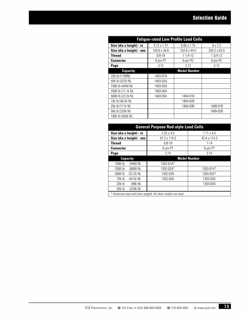
Selection Guide
7.5PCB Piezotronics, Inc. Toll-Free in USA 888-684-0004 716-684-0001 www.pcb.com
General Purpose Rod-style Load CellsSize (dia x height) - in 2.25 x 4.5 1.71 x 4.5 Size (dia x height) - mm 57.2 x 114.3 43.4 x 114.3 Thread 5/8-18 1-14Connector 6-pin PT 6-pin PTPage 3.14 3.14
Capacity Model Number1000 lb (4450 N) 1302-01A*2000 lb (8900 N) 1302-02A* 1303-01A*5000 lb (22.2k N) 1302-03A 1303-02A*
10k lb (44.5k N) 1302-04A 1303-03A20k lb (89k N) 1303-04A50k lb (220k N)
* Aluminum load cells (low weight). All other models are steel.
Fatigue-rated Low Profile Load CellsSize (dia x height) - in 4.12 x 1.37 6.06 x 1.75 8 x 2.5 Size (dia x height) - mm 104.6 x 34.8 153.9 x 44.5 203.2 x 63.5 Thread 5/8-18 1 1/4-12 1 3/4-12Connector 6-pin PT 6-pin PC 6-pin PCPage 3.12 3.12 3.12
Capacity Model Number250 lb (1100N) 1403-01A500 lb (2225 N) 1403-02A1000 lb (4450 N) 1403-03A2500 lb (11.1k N) 1403-04A5000 lb (22.2k N) 1403-05A 1404-01B10k lb (44.5k N) 1404-02B25k lb (111k N) 1404-03B 1408-01B50k lb (220k N) 1408-02B100k lb (450k N)

7.6 PCB Piezotronics, Inc. Toll-Free in USA 888-684-0004 716-684-0001 www.pcb.com
Options
Shunt Resistor — A fixed resistor which is placed in parallel orshunted across a strain gage bridge to provide a known test signalto permit the user with a means of easily performing an accuratesystem calibration of a load cell and signal conditioner.
Dual-Bridge — Provides two signals for purposes of redundancyor to send a signal to two devices, such as a local area display anda data recorder.
Trimmed Output — The output of a strain gage based load cell istypically nominal (± 15%) of specification. A trimmed output iswithin a 1/4% of the specified output.
Metric Threads and Capacities — Our standard product ismanufactured with English attachment threads and Englishcapacities and is calibrated with English standards. All load cellmodels are available with metric attachment threads, metriccapacities, and metric calibration data (converted from Englishcalibration data).
Options For Load Cells

Strain Gage Load Cells
7.7PCB Piezotronics, Inc. Toll-Free in USA 888-684-0004 716-684-0001 www.pcb.com
■ Low-profile
■ Low-deflection
■ Fatigue-rated
■ NIST-traceable calibration
■ Temperature & pressure compensated
Highlights
PCB® manufactures a wide range of strain gage load cells for aerospace, automotive,industrial, and process control applications.
General purpose load cells are suitable for a wide range of routine static forcemeasurement applications, including weighing, dynamometer testing, and materialtesting machines. Most general purpose designs operate in both tension andcompression, and are available in configurations including: canister, low profile and rodend, styles. Capacities from 25 lb to 100k lb (110 N to 450k N) full-scale are available.
Fatigue-rated load cells are specifically designed for fatigue testing machinemanufacturers and users, or in any application where high cyclic loads are present.Applications include material testing, component life cycle testing, and structuraltesting. All fatigue-rated load cells are guaranteed against fatigue failure for 100 millionfully reversed cycles. Capacities are available from 250 lb to 50k lb (1100 N to 220k N)full-scale.
For special or unusual applications, please call to discuss your needs with one of ourforce application specialists.

General Purpose Load Cells / 25-300 lb
7.8 PCB Piezotronics, Inc. Toll-Free in USA 888-684-0004 716-684-0001 www.pcb.com
Series 1102 — general purpose canister-style with 6-pin connector■ Capacities from 25 to 300 lb (110 to 1350 N) FS■ 2 mV/V output sensitivity■ Low profile design
Recommended cables and accessories– see section 8
Select a signal conditioner from those featured in section 8
PT(21R-10-6P)
Series 1102
Dimensions — inches (mm)Series A B C D E F G H J K L T U1102 2.75 (69.9) 1.75 (44.5) 1.5 (38.1) 0.1 (2.5) 0.06 (1.5) 0.75 0.13 (3.3) 2.05 (52.07) 0.22 (5.5) 0.13 (3.3) 0.44 (11.2) 1/4-28 0.38 (9.7)
General Purpose Load Cells Tension and compression measurements
■ component testing ■ weighing■ quality control ■ seat testing■ material testing ■ torque arm

General Purpose Load Cells / 25-300 lb
7.9PCB Piezotronics, Inc. Toll-Free in USA 888-684-0004 716-684-0001 www.pcb.com
Specifications Extraneous Load LimitsModel Capacity Overload Deflection Ringing Weight Material Side Force Bending Moment Torque
Number lb (N) lb (N) at Capacity Frequency lb (gm) Fx or Fy Mx or My Mzin (mm) Hz lb (N) in-lb (N-m) in-lb (N-m)
Canister Load Cells with 6-Pin Connector1102-05A 25 (110) 37.5 (165) 0.003 (0.08) 2100 0.67 (304) aluminum 25 (110) 25 (2.8) 35 (4)1102-01A 50 (225) 75 (330) 0.003 (0.08) 2800 0.67 (304) aluminum 50 (225) 50 (5.6) 35 (4)1102-02A 100 (445) 150 (675) 0.003 (0.08) 3800 0.67 (304) aluminum 100 (445) 100 (11) 65 (7.3)1102-03A 200 (900) 300 (1350) 0.003 (0.08) 5400 0.67 (304) aluminum 200 (900) 200 (23) 65 (7.3)1102-04A 300 (1350) 450 (2000) 0.003 (0.08) 7000 0.67 (304) aluminum 300 (1350) 300 (34) 65 (7.3)
Common Specifications
.
Output (nominal) (±25%) ....................................................2 mV/VNon-linearity (max) ....................................................0.05% FS [1]Hysteresis (max) ........................................................0.05% FS [1]Non-repeatability (max) ............................................0.02% FS [1]Bridge Resistance (nom) ..................................................700 ohmExcitation (recommended) ........................10 Volts DC or AC rms
Temp. Range (compensated) ............................+70 °F to +170 °F (+21 °C to +77 °C)
Temp. Range (usable) ........- 65 °F to +200 °F (-54 °C to +93 °C)Temp. Effect on Zero (max) ..0.002% FS/ °F (0.0036% FS / °C)Temp. Effect on Output (max) ..................0.002% of reading / °F
(0.0036% of reading / °C)
The above chart tabulates maximumextraneous side force, bendingmoment and torque that may beapplied singularly without electricalor mechanical damage to the loadcell. Where combined extraneousloads are applied, decrease aboveloads proportionally.
Wiring Diagram
Note: [1] Model 1102-05A — non-linearity 0.1%, hysteresis 0.1%, non-repeatability 0.05%

Series 1203■ Capacities from 500 to 10k (2225 N to 44.5k N) FS■ 2 mV/V or 3 mV/V output sensitivity■ 6-pin connector■ Optional mounting base available
Recommended cables and accessories– see section 8
Select a signal conditioner from those featured in section 8
Low Profile Load Cells / 500 - 10k lb
7.10 PCB Piezotronics, Inc. Toll-Free in USA 888-684-0004 716-684-0001 www.pcb.com
Low Profile Load Cells For higher range tension and compression measurements
■ component testing ■ bumper impact■ life cycle testing ■ structural testing■ material testing ■ press applications
Series 1203
PT(02E-10-6P)
Series 1203
Load cell shown with optional mounting base.
Dimensions — Inches (mm)Series A B C D E J K L M R T U W Base PN
1203 4.12 (104.6) 1.37 (34.8) 1.27 (32.3) 2.85 (75.5) 0.12 (3.1) 0.28 (7.1) 8 3.5 (88.9) 1/4-28 1.25 (31.8) 5/8-18 0.03 (0.8) 1.13 (28.7) C-30396-6A

Low Profile Load Cells / 500 - 10k lb
7.11PCB Piezotronics, Inc. Toll-Free in USA 888-684-0004 716-684-0001 www.pcb.com
Specifications Extraneous Load LimitsModel Capacity Overload Deflection Ringing Weight Material Side Force Bending Moment Torque
Number lb (N) lb (N) at Capacity Frequency lb (kg) Fx or Fy Mx or My Mzin (mm) Hz lb (N) in-lb (N-m) in-lb (N-m)
Low Profile Aluminum Load Cells with 5/8-18 Thread1203-01A 500 (2225) 750 (3300) 0.002 (0.05) 2350 2.88 (1.31) steel 250 (1100) 250 (28) 250 (28)1203-02A 1000 (4450) 1500 (6675) 0.002 (0.05) 3500 2.88 (1.31) steel 500 (2225) 500 (55) 500 (55)1203-03A 2000 (8900) 3000 (13.3k) 0.001 (0.03) 5500 2.88 (1.31) steel 1000 (4450) 1000 (115) 1000 (115)1203-04A 5000 (22.2k) 7500 (33.3k) 0.0015 (0.038) 7000 2.88 (1.31) steel 2500 (11.1k) 2500 (280) 2500 (280)1203-05A 10k (44.5k) 15k (66.7k) 0.0015 (0.038) 10k 2.88 (1.31) steel 5000 (22.2k) 5000 (565) 5000 (565)
Common Specifications
Output (nominal)500 – 2000k lb Capacity ..........................................................2 mV/V5k – 100k lb Capacity................................................................3 mV/V
Non-linearity (max) ......................................................................0.05% FSHysteresis (max) ..........................................................................0.05% FSNon-repeatability (max) ..............................................................0.02% FSBridge Resistance (nom)................................................................700 ohmExcitation (recommended) ......................................10 Volts DC or AC rms
Temp. Range (compensated) ..........................................+70 °F to +170 °F(+21 °C to +77 °C)
Temp. Range (usable) ......................................................-65 °F to +200 °F(-54 °C to +93 °C)
Temp. Effect on Zero (max) ........................................0.001% FS / °F [2](0.0018% FS / °C)
Temp. Effect on Output (max) ....................................0.002% reading / °F (0.0036% reading / °C)
The above chart tabulates maximumextraneous side force, bendingmoment and torque that may beapplied singularly without electricalor mechanical damage to the loadcell. Where combined extraneousloads are applied, decrease aboveloads proportionally.
Wiring Diagram

7.12 PCB Piezotronics, Inc. Toll-Free in USA 888-684-0004 716-684-0001 www.pcb.com
Series 1204, 1208■ Capacities from 10k to 100k lb (44.5k to 450k N) FS■ 3 mV/V output sensitivity■ 6-pin connector■ Optional mounting base available■ Built-in temperature compensation■ Barometric pressure compensation
Recommended cables and accessories– see section 8
Select a signal conditioner from those featured in section 8
Low Profile Load Cells / 10k - 100k lb
Low Profile Load Cells For higher range tension and compression measurements
■ component testing ■ bumper impact■ Life cycle testing ■ structural testing■ material testing ■ press applications
Series 1204, 1208
PC04A-10-6P
Series 1204, 1208
Load cell shown with optional mounting base.
Dimensions — Inches (mm)Series A B C D E J K L M R T U W Base PN
1204 6.06 (153.9) 1.75 (44.5) 2.42 (61.5) 4.33 (110) 0.12 (3.1) 0.41 (10.4) 12 5.13 (130.3) 3/8-24 2.25 (57.2) 1 1/4-12 0.03 (0.8) 1.75 (44.5) D-30427-3A1208 8 (203.2) 2.5 (63.5) 3.5 (88.9) 5.25 (133.4) 0.25 (6.4) 0.53 (13.5) 16 6.5 (165.1) 1/2-20 3.5 (88.9) 1 3/4-12 0.06 (1.5) 2 (50.8) D-30110-1A

7.13PCB Piezotronics, Inc. Toll-Free in USA 888-684-0004 716-684-0001 www.pcb.com
Low Profile Load Cells / 10k - 100k lb
Specifications Extraneous Load LimitsModel Capacity Overload Deflection Ringing Weight Material Side Force Bending Moment Torque
Number lb (N) lb (N) at Capacity Frequency lb (kg) Fx or Fy Mx or My Mzin (mm) Hz lb (N) in-lb (N-m) in-lb (N-m)
Low Profile Load Cells with 1 1/4-12 Thread1204-01B 10k (44.5k) 15k (66.7k) 0.0015 (0.038) 5500 8.96 (4.06) steel 5000 (22.2k) 5000 (565) 5000 (565)1204-02B 20k (89k) 30k (130k) 0.0015 (0.038) 8000 8.96 (4.06) steel 10k (44.5k) 10k (1130) 10k (1130)1204-03B 50k (220k) 75k (335k) 0.0015 (0.038) 12k 8.96 (4.06) steel 25k (111k) 25k (2825) 25k (2825)
Low Profile Load Cells with 1 3/4-12 Thread1208-01B 50k (220k) 75k (335k) 0.002 (0.05) 8550 25.5 (11.57) steel 25k (111k) 25k (2825) 25k (2825)1208-02B 100k (450k) 150k (667k) 0.002 (0.05) 9550 25.5 (11.57) steel 50k (220k) 50k (5650) 50k (5650)
Common SpecificationsOutput (nominal)
10k – 100k lb Capacity..............................................................3 mV/VNon-linearity (max) ..................................................................0.05% FS [1]
Hysteresis (max)........................................................................0.05% FS [1]
Non-repeatability (max) ............................................................0.02% FS [1]
Bridge Resistance (nom)................................................................700 ohmExcitation (recommended) ......................................10 Volts DC or AC rms
Temp. Range (compensated) ..........................................+70 °F to +170 °F(+21 °C to +77 °C)
Temp. Range (usable) ......................................................-65 °F to +200 °F(-54 °C to +93 °C)
Temp. Effect on Zero (max) ........................................0.001% FS / °F [2](0.0018% FS / °C)
Temp. Effect on Output (max) ....................................0.002% reading / °F (0.0036% reading / °C)
Note: [1] Series 1208 — non-linearity 0.1% FS, hysteresis 0.1%, non-repeatability 0.05%.
The above chart tabulates maximumextraneous side force, bendingmoment and torque that may beapplied singularly without electricalor mechanical damage to the loadcell. Where combined extraneousloads are applied, decrease aboveloads proportionally.
Wiring Diagram

Series 1403 — low profile, fatigue-rated■ Capacities from 250 to 5000k lb (1100 to 22.2k N) FS■ 1 mV/V or 1.5 mV/V output sensitivity■ 6-pin connector■ Fatigue-resistant steel ■ Optional mounting base available■ Over 100 million fully reversed cycles
without failure■ Built-in temperature compensation■ Barometric pressure compensated construction■ Low deflection
Recommended cables and accessories– see section 8
Select a signal conditioner from those featured in section 8
Fatigue-Rated Load Cells / 250 - 5k lb
7.14 PCB Piezotronics, Inc. Toll-Free in USA 888-684-0004 716-684-0001 www.pcb.com
Low Profile,Fatigue-Rated Load Cells Fatigue-rated load cells are rugged devices manufactured using premiumheat-treated, fatigue-resistant steels.
■ material testing ■ component testing■ torque arm ■ life cycle testing■ structural testing ■ calibration standard
Load cell shown withoptional mounting base.
Dimensions — Inches (mm)Series A B C D E J K L M R T U W Base PN1403 4.12 (104.6) 1.37 (34.8) 1.27 (32.3) 2.85 (75.5) 0.12 (3.1) 0.28 (7.1) 8 3.5 (88.9) 5/8-18 1.25 (31.8) 5/8-18 0.03 (0.8) 1.13 (28.7) C-30396-6A
Series 1403
PT(02E-10-6P)
Series 1204

Fatigue-Rated Load Cells / 250 - 5k lb
7.15PCB Piezotronics, Inc. Toll-Free in USA 888-684-0004 716-684-0001 www.pcb.com
Specifications Extraneous Load LimitsModel Capacity Overload Deflection Ringing Weight Material Side Force Bending Moment Torque
Number lb (N) lb (N) at Capacity Frequency lb (kg) Fx or Fy Mx or My Mzin (mm) Hz lb (N) in-lb (N-m) in-lb (N-m)
Fatigue-rated Low Profile Aluminum Load Cells with 5/8-18 Thread1403-01A 250 (1100) 500 (2225) 0.001 (0.03) 2350 2.88 (1.31) steel 250 (1100) 250 (28) 250 (28)1403-02A 500 (2225) 1000 (4450) 0.001 (0.03) 3500 2.88 (1.31) steel 500 (2225) 500 (56) 500 (56)1403-03A 1000 (4450) 2000 (8900) 0.0005 (0.013) 5500 2.88 (1.31) steel 1000 (4450) 1000 (115) 1000 (115)1403-04A 2500 (11.1k) 5000 (22.2k) 0.001 (0.03) 7000 2.88 (1.31) steel 2500 (11.1k) 2500 (280) 2500 (280)1403-05A 5000 (22.2k) 10k (44.5k) 0.001 (0.03) 10k 2.88 (1.31) steel 5000 (22.2k) 5000 (565) 5000 (565)
Common SpecificationsOutput (nominal)
250 – 1000 lb Capacity ..............................................................1 mV/V5k lb Capacity ..........................................................................1.5 mV/V
Non-linearity (max) ........................................................................0.05% FSHysteresis (max) ............................................................................0.05% FSNon-repeatability (max) ................................................................0.02% FS
Bridge Resistance (nom)..................................................................700 ohmExcitation (recommended) ........................................10 Volts DC or AC rmsTemp. Range (compensated) ..............+70 °F to +170 °F (+21 °C to +77 °C)Temp. Range (usable) ..........................-65 °F to +200 °F (-54 °C to +93 °C)Temp. Effect on Zero (max) ..................0.001% FS / °F (0.0018% FS / °C)Temp. Effect on Output ....................................................0.002% reading / °F
(0.0036% reading / °C)
The above chart tabulates maximumextraneous side force, bendingmoment and torque that may beapplied singularly without electricalor mechanical damage to the loadcell. Where combined extraneousloads are applied, decrease aboveloads proportionally.
Wiring Diagram

7.16 PCB Piezotronics, Inc. Toll-Free in USA 888-684-0004 716-684-0001 www.pcb.com
Series 1404, 1408 — low profile, fatigue-rated■ Capacities from 5k to 50k lb (22.2k to 220k N) FS■ 1 mV/V and 1.5 mV/V output sensitivity■ 6-pin connector■ Fatigue-resistant steel ■ Optional mounting base available■ Over 100 million fully reversed cycles
without failure■ Built-in temperature compensation■ Barometric pressure compensated design■ Low deflection
Recommended cables and accessories– see section 8
Select a signal conditioner from those featured in section 8
Fatigue-Rated Load Cells / 5k - 50k lb
Low Profile,Fatigue-Rated Load Cells Fatigue-rated load cells are rugged devices manufactured using premiumheat-treated, fatigue-resistant steels.
■ material testing ■ component testing■ torque arm ■ life cycle testing■ structural testing ■ calibration standard
PC04A-10-6P
Series 1404, 1408
Series 1404, 1408
Load cell shown withoptional mounting base.
Dimensions — Inches (mm)Series A B C D E J K L M R T U W Base PN1404 6.06 (153.9) 1.75 (44.5) 2.42 (61.5) 4.33 (110) 0.12 (3.1) 0.41 (10.4) 12 5.13 (130.3) 3/8-24 2.25 (57.2) 1 1/4-12 0.03 (0.8) 1.75 (44.5) D-30427-3A1408 8 (203.2) 2.5 (63.5) 3.5 (88.9) 5.25 (133.4) 0.25 (6.4) 0.53 (13.5) 16 6.5 (165.1) 1/2-20 3.5 (88.9) 1 3/4-12 0.06 (1.5) 2 (50.8) D-30110-1A

7.17PCB Piezotronics, Inc. Toll-Free in USA 888-684-0004 716-684-0001 www.pcb.com
Fatigue-Rated Load Cells / 5k - 50k lb
The above chart tabulates maximumextraneous side force, bendingmoment and torque that may beapplied singularly without electricalor mechanical damage to the loadcell. Where combined extraneousloads are applied, decrease aboveloads proportionally.
Wiring Diagram
Specifications Extraneous Load LimitsModel Capacity Overload Deflection Ringing Weight Material Side Force Bending Moment Torque
Number lb (N) lb (N) at Capacity Frequency lb (kg) Fx or Fy Mx or My Mzin (mm) Hz lb (N) in-lb (N-m) in-lb (N-m)
Fatigue-rated Low Profile Load Cells with 1 1/4-12 Thread1404-01B 5000 (22.2k) 10k (44.5k) 0.001 (0.03) 5500 8.96 (4.06) steel 5000 (22.2k) 5000 (565) 5000 (565)1404-02B 10k (44.5k) 20k (89k) 0.001 (0.03) 8000 8.96 (4.06) steel 10k (44.5k) 10k (1130) 10k (1130)1404-03B 25k (111k) 50k (222k) 0.001 (0.03) 12k 8.96 (4.06) steel 25k (111k) 25k (2825) 25k (2825)
Fatigue-rated Low Profile Load Cells with 1 3/4-12 Thread1408-01B 25k (110k) 50k (220k) 0.001 (0.03) 6750 25.5 (11.57) steel 25k (111k) 25k (2825) 25k (2825)1408-02B 50k (220k) 100k (450k) 0.001 (0.03) 9550 25.5 (11.57) steel 50k (220k) 50k (5650) 50k (5650)
Common SpecificationsOutput (nominal)
5000 – 50k lb Capacity ............................................................1.5 mV/VNon-linearity (max) ......................................................................0.05% FS [1]
Hysteresis (max) ..........................................................................0.05% FS [1]
Non-repeatability (max) ..............................................................0.02% FS [1]
Bridge Resistance (nom)..................................................................700 ohm
Excitation (recommended) ........................................10 Volts DC or AC rmsTemp. Range (compensated) ..............+70 °F to +170 °F (+21 °C to +77 °C)Temp. Range (usable) ..........................-65 °F to +200 °F (-54 °C to +93 °C)Temp. Effect on Zero (max) ..................0.001% FS / °F (0.0018% FS / °C)Temp. Effect on Output (max) ........................................0.002% reading / °F
(0.0036% reading / °C)
Note: [1] Series 1408 — non-linearity 0.1% FS, hysteresis 0.1%, non-repeatability 0.05%.

Series 1302 — small diameter with female threads■ Capacities from 1000 to 10k lb (4450 to 44.5k N) FS■ 2 mV/V output sensitivity■ 6-pin connector
Recommended cables and accessories– see section 8
Select a signal conditioner from those featured in section 8
Series 1303 — small diameter with male/female threads■ Capacities from 2000 to 20k lb (8900 to 89k N) FS■ 2 mV/V output sensitivity■ 6-pin connector■ Splash-proof construction
Recommended cables and accessories– see section 8
Select a signal conditioner from those featured in section 8
Rod-Style Load Cells / 1000 - 20k lb
7.18 PCB Piezotronics, Inc. Toll-Free in USA 888-684-0004 716-684-0001 www.pcb.com
Small Diameter Rod-Style Load Cells Lower weight aluminum for lower ranged units, high-strength steel forhigher ranged units
■ ideal for tension applications ■ hydraulic actuators■ process automation ■ cable, chain, or wire tension■ quality assurance ■ production monitoring
Series 1303
Series 1302
Dimensions — Inches (mm)Series A B C D E F G H J K L1302 4.5 (114.3) 2.25 (57.2) 0.38 (9.7) 2.75 (69.9) 1.5 (38.1) 2 (50.8) 1 (25.4) 2 (50.8) N/A 5/8-18 0.75 (19.1)1303 4.5 (114.3) 1.71 (43.4) 0.63 (16) 3.5 (88.9) 1.37 (34.8) N/A 1.25 (31.8) 1.44 (36.6) 1-14 1-14 1 (25.4)
PT(21R-10-6P)

Rod-Style Load Cells / 1000 - 20k lb
7.19PCB Piezotronics, Inc. Toll-Free in USA 888-684-0004 716-684-0001 www.pcb.com
Specifications Extraneous Load LimitsModel Capacity Overload Deflection Ringing Weight Material Side Force Bending Moment Torque
Number lb (N) lb (N) at Capacity Frequency lb (kg) Fx or Fy Mx or My Mzin (mm) Hz lb (N) in-lb (N-m) in-lb (N-m)
Rod-style Load Cells with 5/8-18 Female/Female Thread1302-01A 1000 (4450) 1500 (6675) 0.002 (0.05) 2600 1.7 (0.77) aluminum 500 (2225) 1000 (115) 2000 (225)1302-02A 2000 (8900) 3000 (13.3k) 0.002 (0.05) 3500 1.7 (0.77) aluminum 700 (3100) 1500 (170) 3000 (340)1302-03A 5000 (22.2k) 7500 (33.3k) 0.002 (0.05) 3500 4.2 (1.9) steel 2000 (8900) 4000 (450) 4000 (450)1302-04A 10k (44.5k) 15k (66.7k) 0.002 (0.05) 5000 4.2 (1.9) steel 2500 (11.1k) 6000 (675) 6000 (675)
Rod-style Load Cells with 1-1/4-12 Male/Female Thread1303-01A 2000 (8900) 3000 (13.3k) 0.003 (0.08) 6000 0.5 (0.23) aluminum 50 (225) 125 (14) 150 (17)1303-02A 5000 (22.2k) 7500 (33.3k) 0.003 (0.08) 9000 0.5 (0.23) aluminum 150 (667) 500 (56) 600 (68)1303-03A 10k (44.5k) 15k (66.7k) 0.003 (0.08) 8000 1.25 (0.57) steel 300 (1335) 800 (90) 1100 (124)1303-04A 20k (89k) 30k (133k) 0.003 (0.08) 10k 1.25 (0.57) steel 700 (3114) 2000 (226) 3000 (339)
Common Specifications
Model Number 1302 1303Output: mV/Volt (nominal) ....................................2..................................2Non-linearity: % FS (max) ................................0.05 ..............................0.2Hysteresis: % FS (max) ....................................0.05 ..............................0.2Non-repeatability: % FS max)..........................0.02 ............................0.05Bridge Resistance (nom)................................................................350 ohmExcitation (recommended) ......................................10 Volts DC or AC rms
Temp. Range (compensated) ..........................................+70 °F to +170 °F(+21 °C to +77 °C)
Temp. Range (usable) ....................................................- 65 °F to +200 °F(-54 °C to +93 °C)
Temp. Effect on Zero (max) ................................................0.002% FS / °F(0.0036% FS / °C)
Temp. Effect on Output (max) ....................................0.002% reading / °F (0.0036% reading / °C)
The above chart tabulates maximumextraneous side force, bendingmoment and torque that may beapplied singularly without electricalor mechanical damage to the loadcell. Where combined extraneousloads are applied, decrease aboveloads proportionally.
Wiring Diagram

7.20 PCB Piezotronics, Inc. Toll-Free in USA 888-684-0004 716-684-0001 www.pcb.com
Load Cells
Load cell structures may be machined into a variety of configurations to adapt to a multitude ofmeasurement, monitoring, and control applications.
Strain gage sensing elements are examined and tested to insure integrity, accuracy, and longevity.

Load Cell Accessoriesand Services
8.1PCB Piezotronics, Inc. Toll-Free in USA 888-684-0004 716-684-0001 www.pcb.com
■ Strain gage signal conditioners
■ Cable assemblies
■ Mounting accessories
■ Calibration services
Highlights

Series 8159 — Digital Force Indicator / Controller■ Operates from 115 or 230 VAC power■ Provides 5 or 10 VDC strain gage bridge excitation■ Delivers ± 10 Volts and 4 to 20 mA output signals■ 5-digit, red LED display with 1/8 DIN panel mounting■ 4 programmable set points with LED status indicators■ Easy, menu-driven setup■ Optional RS-232 output
Signal Conditioners
8.2 PCB Piezotronics, Inc. Toll-Free in USA 888-684-0004 716-684-0001 www.pcb.com
A variety of signal conditioners are offered for use with strain gageload cells and reaction torque sensors. These units provide the
necessary, regulated excitation voltage and deliver conditionedoutput signals for recording, control, or analysis purposes.
Series 8159
3.78 (96.0)
1.90(48.3)
5.60 (142.2)
Series 8159Dimensions shown are in inches (millimeters)
Base Model
8159 – 115 VAC Powered Indicator with Transducer Excitation
F Prefix for 230 VAC Powered Version (internal jumper selectable)
Communications0 None
1 RS-232 (transmit only)
Sense Leads (internal jumper selectable)
0 Disabled
1 Enabled (recommended for cables >20 ft (6.1 m))
Bridge Excitation (internal jumper selectable)
1 10 VDC
5 5 VDC
Full-scale Input (internal switch selectable)
1 1.5 mV/V
2 2.5 mV/V
3 3.5 mV/V
Version Code
A Initial Release
Example8159– 0 0 1 2 A 115 VAC Powered Indicator with 10 VDC Transducer Excitation and
2.5 mV/V Full Scale Input
How to Order

Series 8160 — In-line Strain Gage Signal Conditioner■ Operates from 12 to 24 VDC power■ Provides 5 or 10 VDC strain gage bridge excitation■ Delivers ± 5 Volts and 4 to 20 mA output signals ■ Adjustable zero and span■ Small size■ Multi-pin input and output connectors■ Built-in, switch-activated, shunt calibration
Signal Conditioners
8.3PCB Piezotronics, Inc. Toll-Free in USA 888-684-0004 716-684-0001 www.pcb.com
Female J1Connector
Male P1Connector
1.68 (42.7)
0.83(21.0)
3.12(79.2)
Series 8160Dimensions shown are in inches
(millimeters)
How to OrderBase Model
8160– In-line Strain Gage Signal Conditioner
Calibrated Output Signal
0 Voltage
1 Current
Bridge Excitation (internal jumper selectable)
1 10 VDC
5 5 VDC
Version Code
A Initial Release
Example8160– 0 1 A Strain gage signal conditioner with ± 5 Volts and 4 to 20 mA output signals,
10 VDC bridge excitation, and calibrated in voltage.
Series 8160

Series 8161 — DIN Rail Mount Signal Conditioner■ Operates from 12 to 28 VDC power■ Provides 5 or 10 VDC strain gage bridge excitation■ Delivers ± 5 or ± 10 Volts and 4 to 20 mA output signals■ Built-in, switch-actuated, shunt calibration
Signal Conditioners
8.4 PCB Piezotronics, Inc. Toll-Free in USA 888-684-0004 716-684-0001 www.pcb.com
Series 8161
2.27 (57.7)0.69(17.5)
3.53 (89.7)
Series 8161Dimensions shown are in inches (millimeters)
How to OrderBase Model8161– DIN Rail Mount Strain Gage Signal Conditioner
Calibrated Output Signal0 Voltage
1 Current
Output Signals (internal jumper selectable)
1 ± 10 Volts and 4 to 20 mA
5 ± 5 Volts and 4 to 20 mA
Bridge Excitation (internal jumper selectable)
1 10 VDC
5 5 VDC
Version CodeA Initial Release
Example8161– 0 1 1 A Strain gage signal conditioner with ± 10 Volts and 4 to 20 mA output signals,
10 VDC bridge excitation, and calibrated in voltage.
Switch Positions for Input Signal Range AdjustmentSensitivity (mV/V)
Vexc = 5 VDC7.0 to 11.04.6 to 7.03.0 to 4.62.0 to 3.01.5 to 2.01.0 to 1.50.9 to 1.0
Sensitivity (mV/V)Vexc = 10 VDC
3.5 to 5.52.3 to 3.51.5 to 2.31.0 to 1.5
0.75 to 1.00.50 to 0.750.45 to 0.50
SW2 Settings1 2 3 40 0 0 10 0 1 00 1 0 01 0 0 01 0 1 01 1 0 11 1 1 1
SW21 = SW “ON”
“ON”10
1 2 3 4

Series 8162 — In-line Strain Gage Signal Conditioner■ Operates from 12 to 28 VDC power■ Provides 5 or 10 VDC strain gage bridge excitation■ Delivers ± 5 or ± 10 Volts and 4 to 20 mA output signals■ Built-in, switch-actuated, shunt calibration■ IP66 (NEMA 4X) enclosure■ Screw terminal connections
Signal Conditioners
8.5PCB Piezotronics, Inc. Toll-Free in USA 888-684-0004 716-684-0001 www.pcb.com
Base Model8162- Strain Gage Signal Conditioner
Calibrated Output Signal0 Voltage
1 Current
Output Signals (internal jumper selectable)
1 ± 10 Volts and 4 to 20 mA
5 ± 5 Volts and 4 to 20 mA
Bridge Excitation (internal jumper selectable)
ˇ 1 10 VDC
5 5 VDC
Version CodeA Initial Release
Example8162- 0 1 1 A Strain gage signal conditioner with ± 10 Volts and 4 to 20 mA output signals,
10 VDC bridge excitation, and calibrated in voltage.
Series 8162
How to Order
3.70 (94.0)2.55 (64.8)
2.23 (56.5)
0.19 (4.8) diamounting hole
(4 places)
Series 8162Dimensions shown are in inches (millimeters)
Switch Positions for Input Signal Range AdjustmentSensitivity (mV/V)
Vexc = 5 VDC7.0 to 11.04.6 to 7.03.0 to 4.62.0 to 3.01.5 to 2.01.0 to 1.50.9 to 1.0
Sensitivity (mV/V)Vexc = 10 VDC
3.5 to 5.52.3 to 3.51.5 to 2.31.0 to 1.5
0.75 to 1.00.50 to 0.750.45 to 0.50
SW2 Settings1 2 3 40 0 0 10 0 1 00 1 0 01 0 0 01 0 1 01 1 0 11 1 1 1
SW21 = SW “ON”
“ON”10
1 2 3 4

8.6 PCB Piezotronics, Inc. Toll-Free in USA 888-684-0004 716-684-0001 www.pcb.com
8311-01-10A Cable assembly for sensors with PT conn., 10-ft, PT conn. to pigtails, 4-cond. cable
8315-01-10A Cable assembly for sensors with PC conn., 10-ft, PC conn. to pigtails, 4-cond. cable
Code Model # Description
Recommended Cables and Accessories

Stock Cable Assemblies
8.7PCB Piezotronics, Inc. Toll-Free in USA 888-684-0004 716-684-0001 www.pcb.com
Load Cell Cable Specifications and Standard Models
The following tables provide specifications and configuration diagrams for the variety of cable types available. Where applicable, standard cableassembly model numbers are provided. Standard models can be less costly than custom cables and available for immediate shipment. For alternatecable lengths or custom models, contact the factory.
Four-Conductor Cables
Usage Construction
General purpose, use with load cells. 24AWG common stranded tinnedcopper drain wire, polypropylene insulated, twisted pair in a chrome PVCjacket. Use when desired cable is < 20 feet (6.1 m).Outer Jacket PVC, greyDiameter 0.168 in 4.27 mmCapacitance 35 pF/ft 44.3 pF/mTemperature Range -4 to +140 ºF -20 to +60 ºCImpedance 45 ohm
Standard Cable AssembliesModel # Length (feet) Length (meters)
8311-01-05A 5 ft 1.5 m8311-01-10A 10 ft 3.0 m
8311-04-05A 5 ft 1.5 m8311-04-10A 10 ft 3.0 m
8311-15-05A 5 ft 1.5 m8311-15-10A 10 ft 3.0 m8311-15-20A 20 ft 6.1 m8311-15-50A 50 ft 15.2 m
Recommended Load Cell Signal Conditioners and CablesRecommended Signal Conditioners
Series 8120 Series 8159 Series 8160A Series 8161A, 8162, & Pigtails
Load Cell Type Recommended CablesLoad cell with PT connector ≤20-ft 8311-04-xxA 8311-17-xxA 8311-15-xxA 8311-01-xxALoad cell with PT connector ≥20-ft 8311-05-xxA 8311-18-xxA 8311-15-xxA 8311-02-xxALoad cell with PC connector <20-ft 8315-04-xxA 8315-17-xxA 8315-15-xxA 8315-01-xxALoad cell with PC connector ≥20-ft 8315-05-xxA 8315-18-xxA 8315-15-xxA 8315-02-xxA”xx” indicates length in feet.[Standard lengths include 5 ft (1.5 m), 10 ft (3 m) 20 ft (6.1 m), & 50 ft (15.2 m).]
PVCJacket
Conductors(4)
Shield
Drain
Continued on next page.
PT 9-pin (M) D-sub
PT Card Edge
PT Pigtails

8.8 PCB Piezotronics, Inc. Toll-Free in USA 888-684-0004 716-684-0001 www.pcb.com
PC Pigtails
PT 9-pin (M) D-sub
Four-Conductor Cables, continued
Standard Cable AssembliesModel # Length (feet) Length (meters)
8311-17-05A 5 ft 1.5 m8311-17-10A 10 ft 3.0 m
8315-01-05A 5 ft 1.5 m8315-01-10A 10 ft 3.0 m
8315-04-05A 5 ft 1.5 m8315-04-10A 10 ft 3.0 m
8315-15-05A 5 ft 1.5 m8315-15-10A 10 ft 3.0 m8315-15-20A 20 ft 6.1 m8315-15-50A 50 ft 15.2 m
8315-17-05A 5 ft 1.5 m8315-17-10A 10 ft 3.0 m
8314-20-05A 5 ft 1.5 m8314-20-10A 10 ft 3.0 m
8314-21-05A 5 ft 1.5 m8314-21-10A 10 ft 3.0 m
Stock Cable Assemblies
PC Card Edge
PC 9-pin (M) D-sub
PC 9-pin (M) D-sub
9-socket (F) D-sub Pigtails
15-socket (F) D-sub Pigtails

8.9PCB Piezotronics, Inc. Toll-Free in USA 888-684-0004 716-684-0001 www.pcb.com
PC 9-pin (M) D-sub
PC Card Edge
PT Card Edge
PT Pigtails
Eight-Conductor Cables
Usage Construction
General purpose, use with load cells. 24AWG common stranded tinnedcopper drain wire, polypropylene insulated, twisted pair in a chrome PVCjacket. Use when desired cable is ≥ 20 feet (6.1 m).Outer Jacket PVC, greyDiameter 0.363 in 9.22 mmCapacitance 13.5 pF/ft 44.3 pF/mTemperature Range -4 to +140 ºF -20 to +60 ºCImpedance 100 ohm
Standard Cable AssembliesModel # Length (feet) Length (meters)
8311-02-20A 20 ft 6.1 m8311-02-50A 50 ft 15.2 m
8311-05-20A 20 ft 6.1 m 8311-05-50A 50 ft 15.2 m
8311-18-20A 20 ft 6.1 m8311-18-50A 50 ft 15.2 m
8315-02-20A 20 ft 6.1 m8315-02-50A 50 ft 15.2 m
8315-05-20A 20 ft 6.1 m8315-05-50A 50 ft 15.2 m
8315-18-20A 20 ft 6.1 m 8315-18-50A 50 ft 15.2 m
PVCJacket
Conductors(8)
Shield
PT 9-pin (M) D-sub
PC Pigtails
Drain
Stock Cable Assemblies

Mating Connectors
8.10 PCB Piezotronics, Inc. Toll-Free in USA 888-684-0004 716-684-0001 www.pcb.com
Mating Connectors
Optional mating connectors are used for load cells and signal conditioners.Model #
181-012AFeatures cable strain relief. For use withload cells which have an “A” at end ofmodel number, and Series 1500 S-beamload cells.
182-025AFeatures cable strain relief. For use withload cells which have a “B” at end of modelnumber, except for Series 1500 S-beamload cells.
182-026AFor transducer connection to Series 8159Signal Conditioner (see page 3.20).
182-027AFor input/output connection to Series 8159Signal Conditioner (see page 3.20).
182-022AFor input/output connection to Series 8160Signal Conditioner (see page 3.21).
182-023AFor transducer connection to Series 8160Signal Conditioner (see page 3.21).
6-socket PT Connector & Back Shell
6-socket PC Connector & Back Shell
9-pin (M) D-sub Connector & Back Shell
15-socket (F) D-sub Connector & Back Shell
9-socket (F) D-sub Connector & Back Shell
9-pin (M) D-sub Connector & Back Shell

8.11PCB Piezotronics, Inc. Toll-Free in USA 888-684-0004 716-684-0001 www.pcb.com
Load Cell Accessories
Rod EndsRod ends are designed to maintain tension loading alignment between a load cell and mounting surface.
Load ButtonsLoad buttons are designed to direct applied forces to the measuring axis of a load cell used in compression.
Series A-20357
Rod EndsModel Thread Dimensions — Inches (mm) a Static Load Weight
Number UNF-3A B W H A D C (deg.) lb (N) lb (g)A-20357-1A 1/4-28 0.19 (4.8) 0.31 (7.9) 0.281 (7.14) 1.56 (39.6) 0.75 (19.1) 1 (25.4) 16 2150 (9600) 0.04 (18)A-20357-2A 3/8-24 0.31 (7.9) 0.44 (11.2) 0.406 (10.3) 1.94 (49.3) 1 (25.4) 1.25 (31.8) 12 5300 (23k) 0.25 (113)A-20357-3A 1/2-20 0.44 (11.2) 0.56 (14.2) 0.5 (12.7) 2.44 (62) 1.312 (33.3) 1.5 (38.1) 12 23k (100k) 0.25 (113)A-20357-4A 5/8-18 0.5 (12.7) 0.63 (16) 0.562 (14.3) 2.63 (66.8) 1.5 (38.1) 1.625 (41.4) 16 31k (135k) 0.38 (172)A-20357-5A 3/4-16 0.63 (16) 0.75 (19.1) 0.687 (17.5) 2.88 (73.2) 1.75 (44.5) 1.75 (44.5) 14 40k (180k) 0.6 (272)A-20357-6A 1-14 1 (25.4) 1.38 (35.1) 1.0 (25.4) 4.13 (104.9) 2.75 (69.9) 2.125 (54.1) 17 43k (190k) 2.1 (953)A-20357-7A 1 1/4-12 1.25 (31.8) 1.09 (27.7) 1.0 (25.4) 4.13 (104.9) 2.75 (69.9) 2.125 (54.1) 17 44k (195k) 2.4 (1089)
Load ButtonModel Thread Dimensions — Inches (mm)
Number T A B CC-20099-1A 1/4-28 0.37 (9.4) 0.25 (6.35) 0.75 (19.1)C-20099-2A 3/8-24 0.5 (12.7) 0.375 (9.53) 2 (50.8)C-20099-3A 1/2-20 0.62 (15.7) 0.5 (12.7) 2 (50.8)C-20099-4A 5/8-18 0.62 (15.7) 0.625 (15.9) 2 (50.8)C-20099-5A 1-14 0.87 (22.1) 0.75 (19.1) 4 (101.6)C-20099-6A 1 1/4-12 1 (25.4) 1.0 (25.4) 4 (101.6)C-20099-7A 2 3/4-8 2.5 (63.5) 1.0 (25.4) 6 (152.4)C-20099-8A 3/4-16 0.6 (15.2) 0.3 (7.6) 6 (152.4)
Series C-20099

8.12 PCB Piezotronics, Inc. Toll-Free in USA 888-684-0004 716-684-0001 www.pcb.com
Load Cell Calibration Services
PCB® maintains a completely equipped calibration laboratory for calibration and re-certification of strain gage based torque sensors, single axis load cells, and multi-axistransducers. These services are available for sensors manufactured by PCB® as well asother companies.
Calibrations and re-certifications performed by PCB® are traceable to the NationalInstitute of Standards and Technology (NIST) and conform to ISO/IEC 17025-1999 andANSI/NCSL Z540-1-1994. PCB®’s calibration laboratory is accredited by The AmericanAssociation for Laboratory Accreditation (A2LA) to ISO 17025.
The scope of our accreditation for load cells is:
10 to 500 lb (0 to 2225 N) 0.04% FS
100 to 10k lb (445 to 45k N) 0.06% FS
10k to 100k lb (45k to 445k N) 0.08% FS
[1] Best Uncertainties represent expanded uncertainties expressed at approximately the 95% confidence level using a coverage factor k = 2.
Basic CalibrationStandard calibration services include five (5) points ascending and descending in tensionand compression. Charted calibration data is provided in a theoretical vs. actual formatwith mV/V, non-linearity, and hysteresis provided at each increment. Shunt calibrationdata is also provided along with a precision shunt calibration resistor. The standardcalibration service includes a basic certificate of NIST traceability.
Range Best Uncertainty [1] (±)
Load Cell Calibration ServicesPCB Sensor Competitor Sensor
Calibration Code Calibration CodeLCS-1A LCS-0 Calibration of load cell, 5-point, single bridge, up to 5000 lb (22.2k N)LCS-1B LCS-0 Calibration of load cell, 5-point, single bridge, above 5000 lb (22.2k N) and up to 50k lb (220k N)LCS-1C LCS-0 Calibration of load cell, 5-point, single bridge, above 50k lb (220k N)LCS-2A LCS-0 System calibration (load cell, signal conditioner, cable), 5-point, single bridge, up to 5000 lb (22.2k N)
LCS-2B LCS-0System calibration (load cell, signal conditioner, cable), 5-point, single bridge, above 5000 lb(22.2k N) and up to 50k lb (220k N)
LCS-2C LCS-0 System calibration (load cell, signal conditioner, cable), 5-point, single bridge, above 50k lb (220k N)Other calibration services available; contact factory for more information.

8.13PCB Piezotronics, Inc. Toll-Free in USA 888-684-0004 716-684-0001 www.pcb.com
Certification of Calibration

8.14 PCB Piezotronics, Inc. Toll-Free in USA 888-684-0004 716-684-0001 www.pcb.com
Series 1302 rod end load cell shown on a durability test rig.
Phot
o co
urte
sy o
f MGA
Res
earc
h Co
rp.

9.1PCB Piezotronics, Inc. Toll-Free in USA 888-684-0004 716-684-0001 www.pcb.com
Load Cell Technical Information
■ Introduction to load cells
■ Glossary of terms
Highlights
PCB® manufactures a wide variety of load cells whose output voltage is proportional tothe applied force produced by a change in resistance in strain gages which are bondedto the load cell’s structure. The magnitude of the change in resistance corresponds to thedeformation of the load cell and therefore the applied load.
The four-arm Wheatstone bridge configuration shown in Figure 1 depicts the straingages used in our load cells. This configuration allows for temperature compensation andcancellation of signals caused by forces not directly applied to the axis of the applied load.
A regulated 5 to 20 volt DC or AC rms excitation is required and is applied between Aand D of the bridge. When a force is applied to the transducer structure, the Wheatstonebridge is unbalanced, causing an output voltage between B and C which is proportionalto the applied load.
Most all PCB® load cells follow a wiring code established by the Western Regional StrainGage committee as revised in May 1960. The code is illustrated in Figure 2.
Our load cells comply with the Axis and Sense Definitions of NAS-938 (NationalAerospace Standard-Machine Axis and Motion) nomenclature and recommendations ofthe Western Regional Strain Gage committee.
These axes are defined in terms of a "right handed" orthogonal coordinate system asshown in Figure 3.
A tensile load exhibits a positive (+) polarity going output, while a compressive loadexhibits a negative (-) polarity going output.
The primary axis of rotation or axis of radial symmetry of a load cell is the z-axis.
PCB® manufactures load cells under two classifications. They are general purpose andfatigue-rated.
General PurposeGeneral purpose load cells are designed for a multitude of applications across theautomotive, aerospace, and industrial markets. The general purpose load cell, as thename implies, is designed to be utilitarian in nature. Within the general purpose load cellmarket there are several distinct categories. They are: precision, universal, weigh scale,and special application. PCB® primarily supplies general purpose load cells into theuniversal and special application categories. Universal load cells are the most commonin industry. Special application load cells are load cells that have been designed for a specific unique force measurement task.
Continued on next page.
Principal of Operation
Axis Definition
Principal of Operation
Figure 1. Wheatstone Bridge
Figure 2. Load Cell Wiring Code
Figure 3. Right-handed Orthogonal Coordinate System

9.2 PCB Piezotronics, Inc. Toll-Free in USA 888-684-0004 716-684-0001 www.pcb.com
Introduction to Load Cells
Special application load cells can be single axis or multiple axis. They include but notlimited to:
■ pedal effort ■ steering column ■ crash barrier ■ hand brake■ femur ■ skid trailer ■ tire test ■ gear shift
Fatigue-rated Load CellsFatigue-rated load cells are specially designed and manufactured to withstand millionsof cycles. They are manufactured using premium fatigue-resistant steel or aluminum andspecial processing to ensure mechanical and electrical integrity, as well as accuracy.Fatigue-rated load cells manufactured by PCB® are guaranteed to last 100 million fullyreversed cycles (full tension through zero to full compression). An added benefit offatigue-rated load cells is their extreme resistance to extraneous bending and sideloading forces.
PCB® typically supplies accuracy information on its products in the form of individualerrors. They are: non-linearity, hysteresis, non-repeatability, effect of temperature onzero, and effect of temperature on output.
The customer can combine individual errors to establish the maximum possible error forthe measurement, or just examine the applicable individual error. If the temperatureremains stable during the test, the temperature related errors can be ignored. If the sensor is used for increasing load measurement only, ignore the hysteresis error. If the load measurement is near the full capacity, the linearity error can be ignored. If thecapability exists to correct the data through linearization-fit or a look-up table, the errorin the measurement can be minimized. A sophisticated user can get rid of all the errorsexcept for the non-repeatability error in the measurement.
Often overlooked by the customer is the error due to the presence of non-measuredforces and bending moments. Even though the single axis of measurement sensors aredesigned and built to withstand these non-measured forces and bending moments(extraneous loads), the errors due to them are present. PCB® engineers can design theset-up to eliminate or minimize these extraneous loads. However, if these extraneousloads are present, the errors due to them should be considered.
Due to cost restraints, PCB®, as with its competition, does not typically measure orcompensate for errors due to extraneous loads. If the presences of these extraneousloads are known, the user should request the transducer manufacturer to run a specialtest, at extra cost, to define and quantify the extraneous load errors. These errors aredefined as cross-talk errors.
Typical Application Examples:Hydraulic Actuators Life Cycle Testing Quality Control
Material Fatigue Testing Torque Arm Tank Weighing
Error Analysis
Determine the capacityrequired
A. What is the maximum expected load?B. What is the minimum expected load?C. What is the typical expected load? D. What are the dynamics of the system,
i.e. frequency response?E. What are the maximum extraneous
loads to which the load cell will be subjected?
How will the load cell beintegrated into the system?
A. What are the physical constraints, e.g.height, diameter, thread?
B. Will the load cell be in the primaryload path or will the load cell seeforces indirectly?
What type of environment willthe load cell be operating in?
A. Maximum temperature?
B. Minimum temperature?C. Humidity?D. Contaminants,
(e.g. water, oil, dirt, dust)?What accuracy is required?
A. Non-linearity?B. Hysteresis?C. Repeatability?D. Cross-talk?
Application Questionnaire

9.3PCB Piezotronics, Inc. Toll-Free in USA 888-684-0004 716-684-0001 www.pcb.com
Accuracy — Stated as a limit tolerance, which defines theaverage deviation between the actual outputversus theoretical output.
In practical transducer applications, thepotential errors of non-linearity, hysteresis,non-repeatability and temperature effects donot normally occur simultaneously, nor arethey necessarily additive.
Therefore, accuracy is calculated based uponRMS value of potential errors, assuming atemperature variation of ± 10 °F (± 5.5 °C),full rated load applied, and proper set-up and calibration. Potential errors of the readout,cross-talk, or creep effects are not included.
Ambient Conditions — The conditions (humidity, pressure,temperature, etc.) of the medium surroundingthe transducer.
Ambient Temperature — The temperature of the medium surroundingof transducers.
Calibration — The comparison of transducer output againststandard test loads.
Calibration Curve — a record (graph) of the comparison oftransducer output against standard testloads.
Combined Error —(Non-linearity and Hysteresis) — themaximum deviation from a straight linedrawn between the original no-load andrated load outputs expressed as apercentage of the rated output and measuredon both increasing and decreasing loads.
Compensation — The utilization of supplementary devices,materials, or processes to minimize knownsources of error.
Creep — The change of transducer output occurringwith time, while under load, and with allenvironmental conditions and other variablesremaining constant.Note: Usually measured with rated load appliedand expressed as a percent of rated output over aspecific period of time.
Creep Recovery — The change in no-load output occurring withtime, after removal of a load, which has beenapplied for a specific period of time.
Cross-Talk — With one component loaded to capacity, andthe other unloaded, the output of theunloaded component will not exceed thepercentage specified of its full-scale capacity.
Deflection — The change in length along the primary axisof the load cell between no-load and ratedload conditions.
Drift — A random change in output under constantload conditions.
Error — The algebraic difference between theindicated and true value of the load beingmeasured.
Excitation, Electrical — The voltage or current applied to the inputterminals of the transducer.
Fatigue Capacity — Capacity as percentage of the nominal loadlimit capacity, and based on 100 X 10^6cycles (minimum) from zero to full fatiguecapacity and 50 X 10^6 cycles (minimum)from full fatigue capacity tension to fullfatigue capacity compression load.
Hysteresis — The maximum difference between thetransducer output readings for the sameapplied load, one reading obtained byincreasing the load from zero and the otherby decreasing the load from rated load.Note: Usually measured at half rated output and expressed in percent of rated output.Measurements should be taken as rapidly as possible to minimize creep.
Insulation Resistance — The DC resistance measured between thetransducer circuit and the transducerstructure.Note: Normally measured at 50 Volts DC andunder standard test conditions.
Natural Frequency — The frequency of free oscillations under no-load conditions.
Nominal Load Limit Capacity — It is the designed normal maximum capacityof a transducer. Output sensitivity of thetransducer is based on this capacity unlessspecified.
Non-linearity — The maximum deviation of the calibrationcurve from a straight line drawn between theno load and rated load output, expressed asa percentage of the rated output andmeasured on increasing load only.
Output — This signal (voltage, current, etc.) producedby the transducer.Note: Where the output is directly proportional toexcitation, the signal must be expressed in termsof volts per volt, volts per ampere, etc., of excitation.
Output, Rated — The algebraic difference between theoutputs at no-load and at rated load.
Overload Rating — The maximum load in percent of ratedcapacity, which can be applied withoutproducing a permanent shift in performancecharacteristics beyond those specified.
Primary Axis — The axis along which the transducer isdesigned to be loaded; normally itsgeometric centerline.
Rated Capacity (Rated Load) — The maximum axial load that the transduceris designed to measure within itsspecifications.
Repeatability — The maximum difference betweentransducer output readings for repeatedloading under identical loading andenvironmental conditions.
Resolution — The smallest change in mechanical input,which produces a detectable change in theoutput signal.
Glossary of Terms

9.4 PCB Piezotronics, Inc. Toll-Free in USA 888-684-0004 716-684-0001 www.pcb.com
Sensitivity — The ratio of the change in output to thechange in mechanical input.
Shunt Calibration — Electrical simulation of transducer output byinsertion of known shunt resistors betweenappropriate points within the circuitry.
Shunt-to-load Correlation — The difference in output readings obtainedthrough electrically simulated and actualapplied loads.
Standard Test Conditions — The environmental conditions under whichmeasurements should be made, whenmeasurements under any other conditionsmay result in disagreement between variousobservers at difference times and places.These conditions are a follows:
Temperature 72 °F ± 3.6 °F (23 °C ± 2 °C)
Relative Humidity: 90% or less
Barometric Pressure: 28 to 32 inch Hg
Static Extraneous Load Limits — Static Extraneous Load Limits are calculatedsuch that only one extraneous load (Fx or Fy or Mx or My or Mz) can be appliedsimultaneously with 50% of the nominalload limit applied.
Temperature Effect on Output — The change in output due to a change intransducer temperature.Note: Usually expressed as a percentage of loadreading per degree Fahrenheit change in temperature.
Temperature Effect on Zero Balance —The change in zero balance due to a changein transducer temperature.Note: Usually expressed as the change in zerobalance in percent of rated output per degreesFahrenheit (change in temperature).
Temperature Range,Compensated —The range of temperature over which thetransducer is compensated to maintain ratedoutput and zero balance within specified limits.
Temperature Range, Usable —The extremes of temperature within whichthe transducer will operate without permanentadverse change to any of its performancecharacteristics.
Terminal Resistance — The resistance of the transducer circuitmeasured at specific adjacent bridgeterminals at standard temperature, with no-load applied, and with the excitation and output terminals open-circuited.
Terminal Resistance,Excitation — The resistance of the transducer circuitmeasured at the excitation terminals, atstandard temperature, with no-load applied,and with the output terminals open-circuited.
Terminal Resistance, Signal — The resistance of the transducer circuitmeasured at the output signal terminals, atstandard temperature, with no-load applied,and with the excitation terminals open-circuited.
Traceability — The step-by-step transducer process bywhich the transducer calibration can berelated to primary standards.
Zero Balance — The output signal of the transducer withrated excitation and with no-load applied,usually expressed in percent of rated output.
Zero Return — The difference in zero balance measuredimmediately before rated load application ofspecified duration and measured afterremoval of the load, and when the output hasstabilized.
Zero Shift, Permanent — A permanent change in the no-load output.
Zero Stability — The degree to which the transducermaintains its zero balance with allenvironmental conditions and other variablesremaining constant.
Application Notes andTechnical ArticlesTo order copies of the following applicationnotes, call PCB® toll-free at 888-684-0004.
Application NotesAP-1001 Extraneous Loads
AP-1002 Equivalent Force of a Falling Object
AP-1003 Mechanical Installation of PCB®
Torque Transducers
AP-1004 Installation of PCB® Driveline TorqueTransducers
AP-1007 Dynamometer Installation of PCB®
Model 1401 Load Cell
AP-1008 Spline Lubrication PCB® Model 4115A & K, Preliminary Release
AP-1009 Explosive Environment
AP-1011 Effects of Thrust and BendingMoment on The Torque Output ofTorque Disk. Model 5304-101-01
AP-1012 Grease Lubrication
AP-1015 Effects of Extraneous Loads onTORKDISC® Series 5308 and 5309
AP-1016 Shunt Calibration of a Strain GageSensor
Technical Articles TA-1001 What is a Transducer?
TA-1002 Cross-talk in a Multi-ComponentSensor
TA-1003 Accuracy
Glossary of Terms

Notes
9.5PCB Piezotronics, Inc. Toll-Free in USA 888-684-0004 716-684-0001 www.pcb.com

9.6 PCB Piezotronics, Inc. Toll-Free in USA 888-684-0004 716-684-0001 www.pcb.com
Notes

PCB Group Companies
PCB®, IMI Sensors and Larson Davis, are members of the PCB “Measurement”Group, a family of technology-based companies offering a wide range of sensortechnologies. With PCB Piezotronics as its flagship, individual PCB Groupcompanies and their core competencies include:
PCB Piezotronics, Inc. (www.pcb.com) specializes in piezoelectric, ICP®,charge output, piezoresistive and capacitive accelerometers, microphones, pressuresensors, force sensors, load cells, torque sensors, and signal conditioners for test,measurement, monitoring, and research & development.Toll-free in USA: 800-828-8840 ■ 24-hour SensorLine
SM
: 716-684-0001
IMI Sensors (www.imi-sensors.com) division of PCB Piezotronicsspecializes in vibration sensors, transmitters, switches, instrumentation, andaccessories for machinery vibration monitoring and predictive maintenance inharsh industrial environments.Toll-free in USA: 800-959-446424-hour SensorLine
SM
: 716-684-0001
Larson Davis (www.larsondavis.com) division of PCB Piezotronicsspecializes in sound level meters and precision microphones, portable and fixednoise monitoring systems, noise dosimeters, human vibration meters, and reportgeneration software for industrial hygiene.Toll-free in USA: 888-258-3222 ■ Phone: 716-926-8243
The Modal Shop, Inc. (www.modalshop.com) specializes in multi-channel sound and vibration sensing systems for lab measurements and industrialprocess monitoring, including calibration systems and test and measurement equipmentrental. Also, smart sensing systems applied to parts quality NDT analysis, processmonitoring and machinery gauging.Toll-free in USA: 800-860-4867 ■ Phone: 513-351-9919
Oceana Sensor Technologies (www.oceanasensor.com) specializesin automated assembly of piezoelectric sensors for high-volume, low-cost OEMapplications; Wireless e-Diagnostics® products, highlighting open system wirelessplatforms, including Bluetooth® and 802.11b.Phone: 757-426-3678
STI Technologies, Inc. (www.sti-tech.com) is a mechanical engineeringconsulting firm specializing in finite element analysis, advanced analytical techniques,experimentation, technology development, and design optimization for life prediction,condition-based monitoring, as well as performance enhancement of turbomachinery,rotating machinery systems, and mechanical structures/components. Phone: 585-424-2010
PCB Machining Solutions, Inc. (www.pcbmsi.com) specializes inprecision machine components for the industrial, medical, aerospace, and defenseindustries. Phone: 716-823-3193
Dep
ew, N
ew Y
ork
Prov
o, U
tah
Cinc
inna
ti, O
hio
Virg
inia
Bea
ch, V
irgi
nia
Roch
este
r, N
ew Y
ork
Lack
awan
na, N
ew Y
ork

Visit www.pcb.com to locate your nearest sales office
PCB Piezotronics, Inc. 3425 Walden Avenue, Depew, NY 14043-2495 USA USA Toll-Free ☎ 888-684-0004 24-hour SensorLineSM ☎ 716-684-0001 Fax, 716-684-8877 E-mail* [email protected] Web www.pcb.com
ISO 9001:2000 Certified A2LA Accredited to ISO 17025 AS9100:2004 CertifiedPCB Piezotronics, Inc. manufactures accelerometers, force sensors, load cells, microphones, pressure transducers and transmitters,strain sensors, torque sensors, vibration sensors, signal conditioners, cables, and accessories. This instrumentation is used for test,measurement, monitoring, and feedback control requirements in automotive, aerospace, industrial, R&D, military, educational,commercial, and OEM applications. PCB Piezotronics offers exceptional customer service, 24-hour technical assistance, and aTotal Customer Satisfaction guarantee.© 2007 PCB Group, Inc. In the interest of constant product improvement, specifications are subject to change without notice. PCB, ICP, IMI with associated logo, and
Torkdisc are registered trademarks of PCB Group, Inc. SensorLine is a service mark of PCB Group, Inc. All other trademarks are properties of their respective owners.
FTQ-200G-0107 Printed in U.S.A.
PCB Piezotronics – Worldwide Offices
Corporate HeadquartersPCB Piezotronics, Inc.3425 Walden AvenueDepew, NY 14043-2495 USA24-hour SensorLineSM 716-684-0001Fax: 716-684-0987E-mail: [email protected]
Shock & Vibration Toll-Free in USA: 888-684-0013E-mail: [email protected]: 716-685-3886
IMI SensorsToll-Free in USA: 800-959-4464E-mail: [email protected]: 716-684-3823
Force, Torque, Load, & StrainToll-Free in USA: 888-684-0004E-mail: [email protected]: 716-684-8877
PressureToll-Free in USA: 888-684-0011E-mail: [email protected]: 716-686-9129
AcousticsToll-Free in USA: 800-258-3222E-mail: [email protected]: 716-926-8215
Domestic Sales OfficesNew York StatePhone: 888-843-4648 ■ Fax: 585-547-2395E-mail: [email protected]
CentralPhone: 888-412-7191 ■ Fax: 636-272-0291E-mail: [email protected]
Central-EastPhone: 888-412-7196 ■ Fax: 865-777-0587E-mail: [email protected]
CharlottePhone: 888-538-9700 ■ Fax: 803-628-0759E-mail: [email protected]
ChicagoPhone: 888-412-7193 ■ Fax: 815-399-5587E-mail: [email protected]
ClevelandPhone: 888-412-7101 ■ Fax: 440-647-4764E-mail: [email protected]
CincinnatiPhone: 888-412-7043 ■ Fax: 513-575-3288E-mail: [email protected]
Gulf CoastPhone: 888-412-7097 ■ Fax: 509-357-0659E-mail: [email protected]
MichiganPhone: 888-412-7106 ■ Fax: 586-754-5993E-mail: [email protected]
Mid-AtlanticPhone: 888-412-7192 ■ Fax: 804-378-1850E-mail: [email protected]
MidwestPhone: 888-412-9565 ■ Fax: 608-368-1337E-mail: [email protected]
Northern CaliforniaPhone: 888-412-7412 ■ Fax: 831-426-7019E-mail: [email protected]
NortheastPhone: 888-412-7038 ■ Fax: 610-430-1249E-mail: [email protected]
NorthwestPhone: 866-508-7352 ■ Fax: 716-684-0987Email: [email protected]
PhiladelphiaPhone: 888-412-7413 ■ Fax: 215-684-2497E-mail: [email protected]
SoutheastPhone: 888-412-9560 ■ Fax: 386-532-9164E-mail: [email protected]
Southern CaliforniaPhone: 888-412-9563 ■ Fax: 714-970-1133E-mail: [email protected]
SouthwestPhone: 888-425-4722 ■ Fax: 480-671-9125E-mail: [email protected]
Worldwide Sales OfficesChinaPCB Piezotronics, Inc.Beijing Representative OfficePhone: (86) 010 84477840 Fax: (86) 010 84477840E-mail: [email protected]
Shanghai Representative OfficePhone: (86) 021 6374 1517 Fax: (86) 021 6374 1510Email: [email protected]
FrancePCB Piezotronics SAPhone: +33 (0) 1 69 33 1960Fax: +33 (0) 1 69 33 1976E-mail: [email protected]
GermanySynotech GmbHPhone: +49 (0) 2462 99190Fax: +49 (0) 2462 99197E-mail: [email protected]
ItalyPCB Piezotronics srlPhone: +39 035 201421 Fax: +39 035 203754Email: [email protected]
JapanToyo Corporation - Team PCBPhone: +81 (0) 3 3245 1240Fax: +81 (0) 3 5205 2030E-mail: [email protected]
SwedenPCB Scandinavia ABPhone: +46 (0) 8 444 3870 Fax: +46 (0) 8 444 3875E-mail: [email protected]
United KingdomPCB Piezotronics Ltd.Phone: +44 (0) 1462 429710 Fax: +46 (0) 1462 429798E-mail: [email protected]