
Boolean algebra This worksheet and all related files are licensed ...
Dynamic fluids
This worksheet and all related files are licensed under the Creative Commons Attribution License,version 1.0. To view a copy of this license, visit http://creativecommons.org/licenses/by/1.0/, or send aletter to Creative Commons, 559 Nathan Abbott Way, Stanford, California 94305, USA. The terms andconditions of this license allow for free copying, distribution, and/or modification of all licensed works bythe general public.
This worksheet introduces the basic concepts of gases and liquids in motion.
1
Questions
Question 1
Water flowing through an 8-inch pipe at an average velocity of 5 feet per second enters a narrowersection of pipe (3 inches), changing its velocity accordingly. Calculate the water’s average velocity in thisnarrower section of pipe.
file i04796
Question 2
Crude oil flows at an average velocity of 14 feet per second through a pipe with an internal diameter of7.92 inches. Calculate the flow rate of this oil in units of gallons per minute, as well as barrels per day.
file i04797
Question 3
Crude oil flows at an average velocity of 10 feet per second through a pipe with an internal diameter of5.95 inches. Calculate the flow rate of this oil in units of gallons per minute, as well as barrels per day.
file i04785
Question 4
Calculate the average velocity of gasoline flowing through a 6-inch pipe at a flow rate of 180 GPM.file i04788
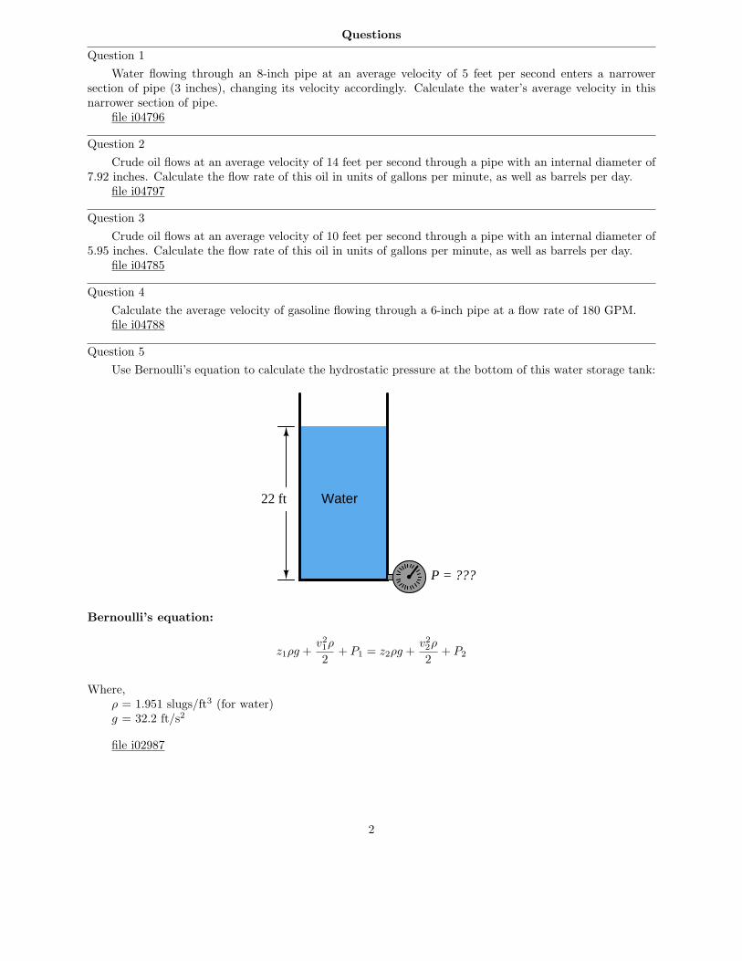
Question 5
Use Bernoulli’s equation to calculate the hydrostatic pressure at the bottom of this water storage tank:
22 ft Water
P = ???
Bernoulli’s equation:
z1ρg +v2
1ρ
2+ P1 = z2ρg +
v2
2ρ
2+ P2
Where,ρ = 1.951 slugs/ft3 (for water)g = 32.2 ft/s2
file i02987
2
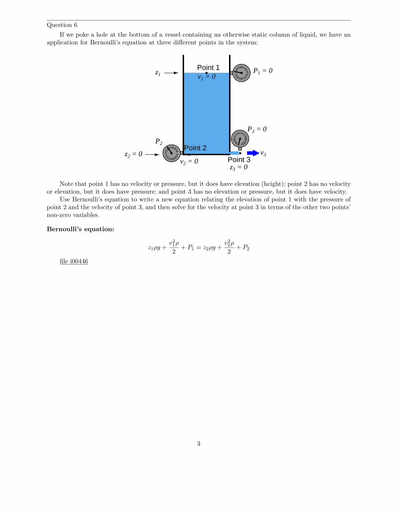
Question 6
If we poke a hole at the bottom of a vessel containing an otherwise static column of liquid, we have anapplication for Bernoulli’s equation at three different points in the system:
P2
P1 = 0z1
z2 = 0
Point 1
P3 = 0
Point 2
Point 3v3
v2 = 0
v1 = 0
z3 = 0
Note that point 1 has no velocity or pressure, but it does have elevation (height); point 2 has no velocityor elevation, but it does have pressure; and point 3 has no elevation or pressure, but it does have velocity.
Use Bernoulli’s equation to write a new equation relating the elevation of point 1 with the pressure ofpoint 2 and the velocity of point 3, and then solve for the velocity at point 3 in terms of the other two points’non-zero variables.
Bernoulli’s equation:
z1ρg +v2
1ρ
2+ P1 = z2ρg +
v2
2ρ
2+ P2
file i00446
3
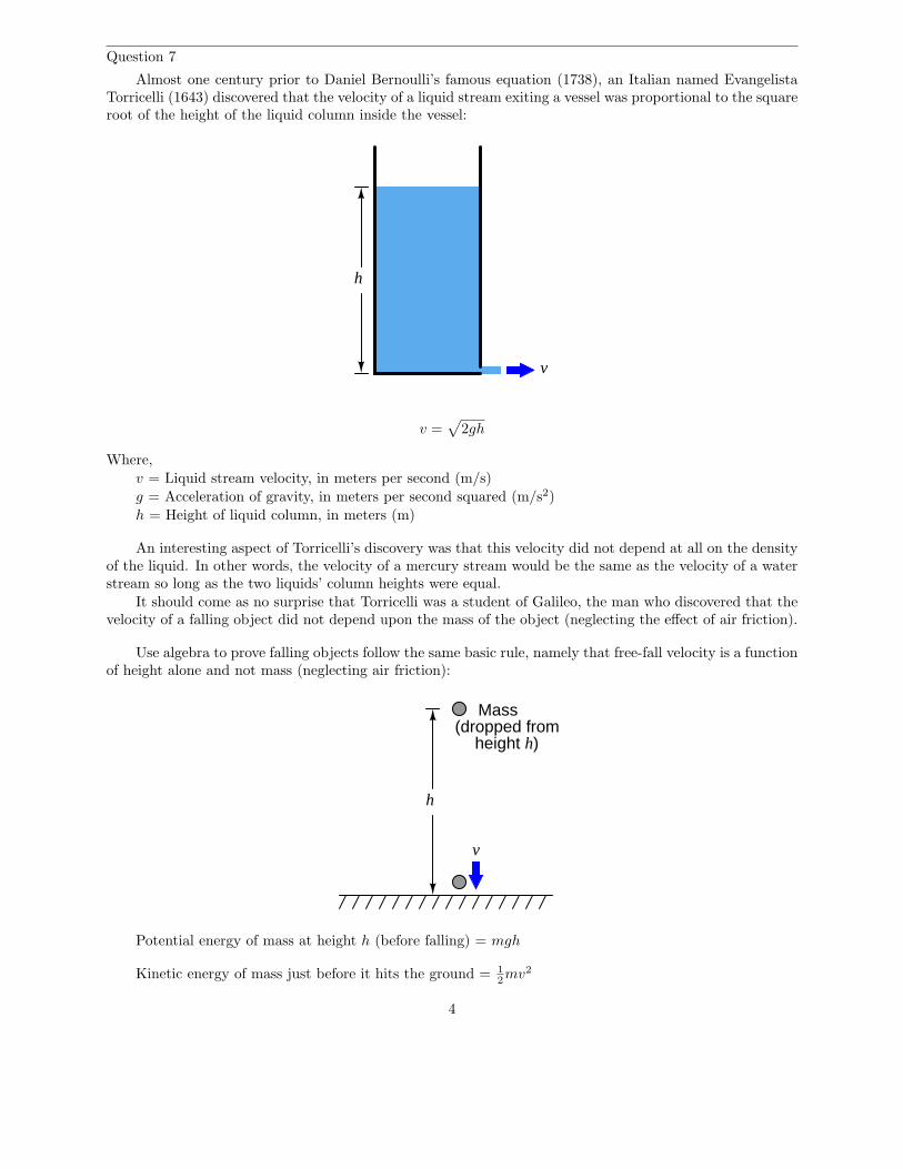
Question 7
Almost one century prior to Daniel Bernoulli’s famous equation (1738), an Italian named EvangelistaTorricelli (1643) discovered that the velocity of a liquid stream exiting a vessel was proportional to the squareroot of the height of the liquid column inside the vessel:
v
h
v =√
2gh
Where,
v = Liquid stream velocity, in meters per second (m/s)
g = Acceleration of gravity, in meters per second squared (m/s2)
h = Height of liquid column, in meters (m)
An interesting aspect of Torricelli’s discovery was that this velocity did not depend at all on the densityof the liquid. In other words, the velocity of a mercury stream would be the same as the velocity of a waterstream so long as the two liquids’ column heights were equal.
It should come as no surprise that Torricelli was a student of Galileo, the man who discovered that thevelocity of a falling object did not depend upon the mass of the object (neglecting the effect of air friction).
Use algebra to prove falling objects follow the same basic rule, namely that free-fall velocity is a functionof height alone and not mass (neglecting air friction):
v
h
Mass(dropped from
height h)
Potential energy of mass at height h (before falling) = mgh
Kinetic energy of mass just before it hits the ground = 1
2mv2
4
Do you notice a similarity between the Torricelli’s formula and the one you derived from the potentialand kinetic energy equations?
file i00447
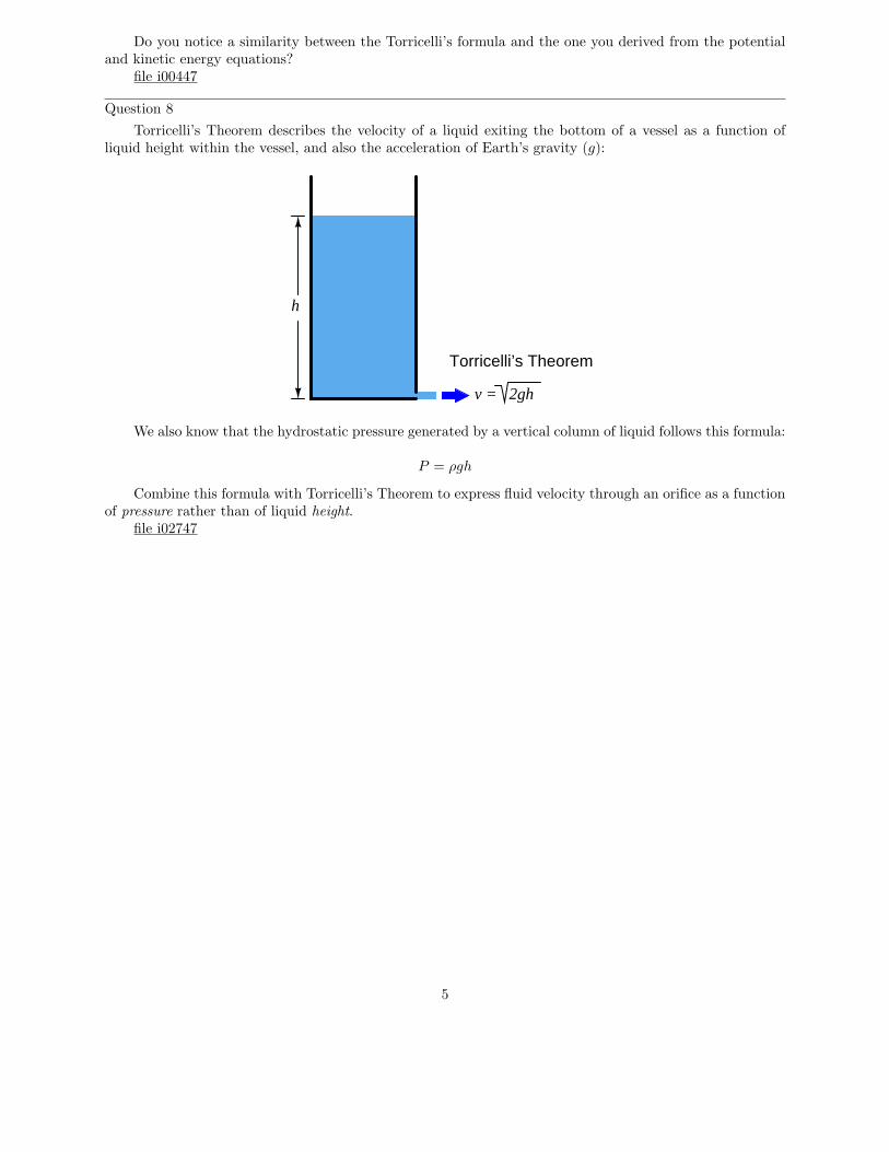
Question 8
Torricelli’s Theorem describes the velocity of a liquid exiting the bottom of a vessel as a function ofliquid height within the vessel, and also the acceleration of Earth’s gravity (g):
h
v = 2gh
Torricelli’s Theorem
We also know that the hydrostatic pressure generated by a vertical column of liquid follows this formula:
P = ρgh
Combine this formula with Torricelli’s Theorem to express fluid velocity through an orifice as a functionof pressure rather than of liquid height.
file i02747
5
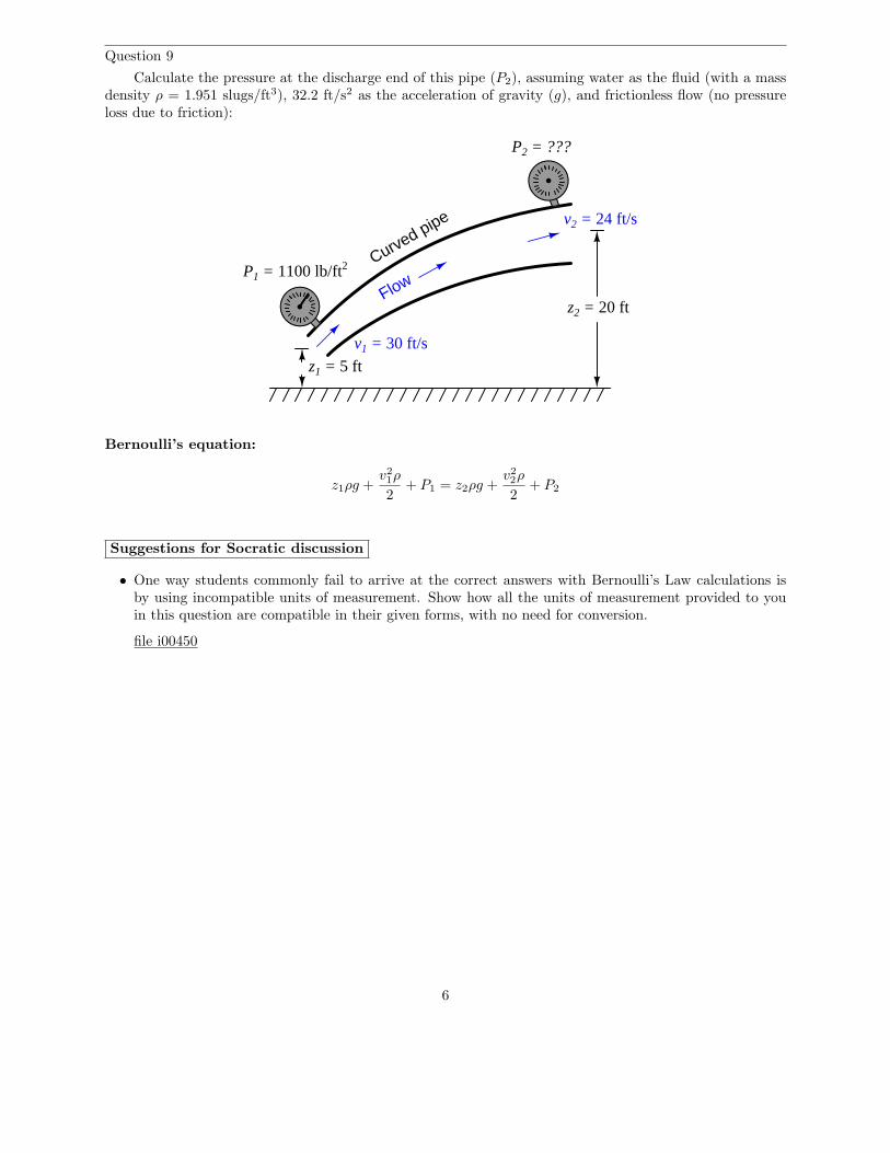
Question 9
Calculate the pressure at the discharge end of this pipe (P2), assuming water as the fluid (with a massdensity ρ = 1.951 slugs/ft3), 32.2 ft/s2 as the acceleration of gravity (g), and frictionless flow (no pressureloss due to friction):
Curved pipe
Flow
z1 = 5 ft
z2 = 20 ft
v1 = 30 ft/s
v2 = 24 ft/s
P2 = ???
P1 = 1100 lb/ft2
Bernoulli’s equation:
z1ρg +v2
1ρ
2+ P1 = z2ρg +
v2
2ρ
2+ P2
Suggestions for Socratic discussion
• One way students commonly fail to arrive at the correct answers with Bernoulli’s Law calculations isby using incompatible units of measurement. Show how all the units of measurement provided to youin this question are compatible in their given forms, with no need for conversion.
file i00450
6
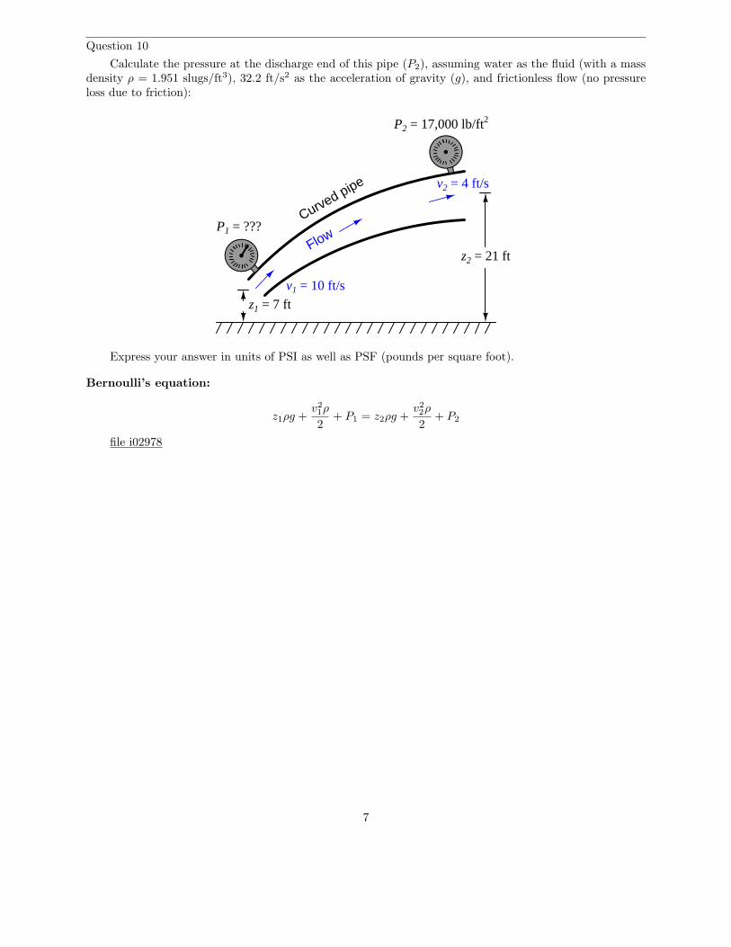
Question 10
Calculate the pressure at the discharge end of this pipe (P2), assuming water as the fluid (with a massdensity ρ = 1.951 slugs/ft3), 32.2 ft/s2 as the acceleration of gravity (g), and frictionless flow (no pressureloss due to friction):
Curved pipe
Flow
P2 = 17,000 lb/ft2
P1 = ???
v1 = 10 ft/s
v2 = 4 ft/s
z1 = 7 ft
z2 = 21 ft
Express your answer in units of PSI as well as PSF (pounds per square foot).
Bernoulli’s equation:
z1ρg +v2
1ρ
2+ P1 = z2ρg +
v2
2ρ
2+ P2
file i02978
7
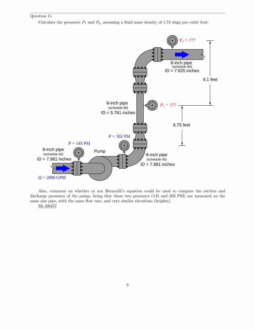
Question 11
Calculate the pressures P1 and P2, assuming a fluid mass density of 1.72 slugs per cubic foot:
Pump8-inch pipe
6-inch pipe
8-inch pipe
(schedule 40)
(schedule 80)
(schedule 80)
ID = 7.981 inches
ID = 5.761 inches
ID = 7.625 inches
P = 145 PSI
P = 302 PSI
P1 = ???
P2 = ???
6.75 feet
9.1 feet
8-inch pipe(schedule 40)
ID = 7.981 inches
Q = 2000 GPM
Also, comment on whether or not Bernoulli’s equation could be used to compare the suction anddischarge pressures of the pump, being that those two pressures (145 and 302 PSI) are measured on thesame size pipe, with the same flow rate, and very similar elevations (heights).
file i00457
8
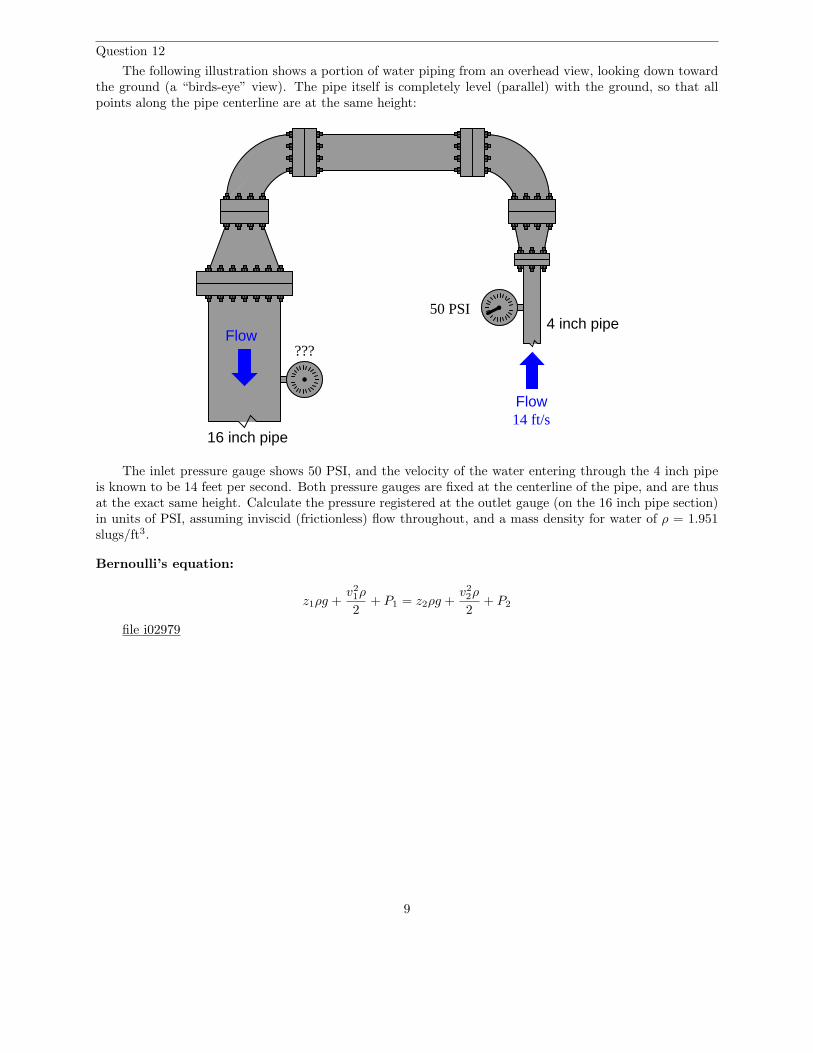
Question 12
The following illustration shows a portion of water piping from an overhead view, looking down towardthe ground (a “birds-eye” view). The pipe itself is completely level (parallel) with the ground, so that allpoints along the pipe centerline are at the same height:
???
4 inch pipe
16 inch pipe
Flow
Flow
50 PSI
14 ft/s
The inlet pressure gauge shows 50 PSI, and the velocity of the water entering through the 4 inch pipeis known to be 14 feet per second. Both pressure gauges are fixed at the centerline of the pipe, and are thusat the exact same height. Calculate the pressure registered at the outlet gauge (on the 16 inch pipe section)in units of PSI, assuming inviscid (frictionless) flow throughout, and a mass density for water of ρ = 1.951slugs/ft3.
Bernoulli’s equation:
z1ρg +v2
1ρ
2+ P1 = z2ρg +
v2
2ρ
2+ P2
file i02979
9
Question 13
Elevation (z) and pressure (P ) readings are taken at two different points in a piping system carryingliquid benzene (γ = 56.1 lb/ft3):
z1 = 50 inches z2 = 34 inches
P1 = 70 PSI P2 = 69 PSI
Calculate the fluid velocity at point 2 (v2) if the velocity at point 1 is known to be equal to 5 feet persecond (v1 = 5 ft/s).
Bernoulli’s equation:
z1ρg +v2
1ρ
2+ P1 = z2ρg +
v2
2ρ
2+ P2
file i02988
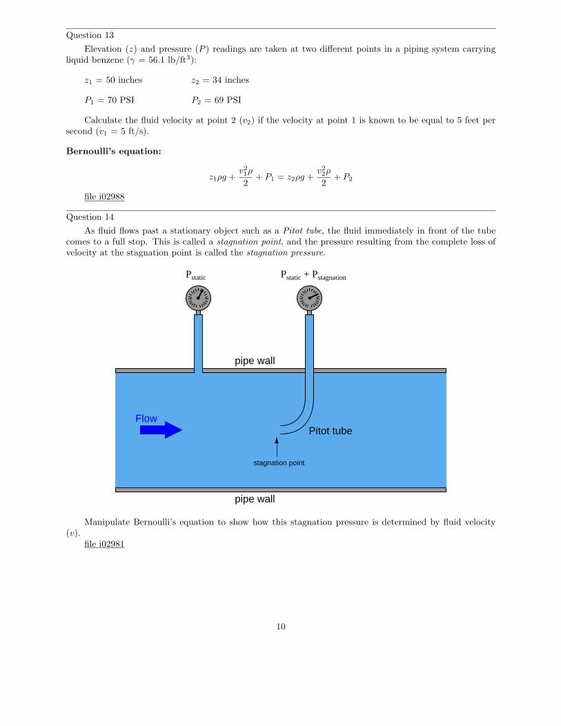
Question 14
As fluid flows past a stationary object such as a Pitot tube, the fluid immediately in front of the tubecomes to a full stop. This is called a stagnation point, and the pressure resulting from the complete loss ofvelocity at the stagnation point is called the stagnation pressure.
Flow
pipe wall
pipe wall
Pitot tube
Pstatic Pstatic + Pstagnation
stagnation point
Manipulate Bernoulli’s equation to show how this stagnation pressure is determined by fluid velocity(v).
file i02981
10
Question 15
Calculate the pressure developed by a Pitot tube measuring air speed at 50 MPH, at sea level (ρair =0.00235 slugs/ft3).
Also, how much pressure will the Pitot tube develop at twice the air speed (100 MPH)?file i02982
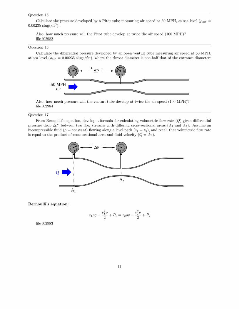
Question 16
Calculate the differential pressure developed by an open venturi tube measuring air speed at 50 MPH,at sea level (ρair = 0.00235 slugs/ft3), where the throat diameter is one-half that of the entrance diameter:
∆P
50 MPHair
Also, how much pressure will the venturi tube develop at twice the air speed (100 MPH)?file i02984
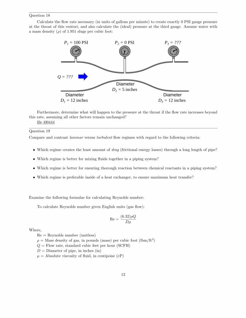
Question 17
From Bernoulli’s equation, develop a formula for calculating volumetric flow rate (Q) given differentialpressure drop ∆P between two flow streams with differing cross-sectional areas (A1 and A2). Assume anincompressible fluid (ρ = constant) flowing along a level path (z1 = z2), and recall that volumetric flow rateis equal to the product of cross-sectional area and fluid velocity (Q = Av).
Q
∆P
A1
A2
Bernoulli’s equation:
z1ρg +v2
1ρ
2+ P1 = z2ρg +
v2
2ρ
2+ P2
file i02983
11
Question 18
Calculate the flow rate necessary (in units of gallons per minute) to create exactly 0 PSI gauge pressureat the throat of this venturi, and also calculate the (ideal) pressure at the third gauge. Assume water witha mass density (ρ) of 1.951 slugs per cubic foot:
DiameterD1 = 12 inches
Diameter
DiameterD3 = 12 inches
D2 = 5 inches
Q = ???
P1 = 100 PSI P2 = 0 PSI P3 = ???
Furthermore, determine what will happen to the pressure at the throat if the flow rate increases beyondthis rate, assuming all other factors remain unchanged?
file i00444
Question 19
Compare and contrast laminar versus turbulent flow regimes with regard to the following criteria:
• Which regime creates the least amount of drag (frictional energy losses) through a long length of pipe?
• Which regime is better for mixing fluids together in a piping system?
• Which regime is better for ensuring thorough reaction between chemical reactants in a piping system?
• Which regime is preferable inside of a heat exchanger, to ensure maximum heat transfer?
Examine the following formulae for calculating Reynolds number:
To calculate Reynolds number given English units (gas flow):
Re =(6.32)ρQ
Dµ
Where,
Re = Reynolds number (unitless)
ρ = Mass density of gas, in pounds (mass) per cubic foot (lbm/ft3)
Q = Flow rate, standard cubic feet per hour (SCFH)
D = Diameter of pipe, in inches (in)
µ = Absolute viscosity of fluid, in centipoise (cP)
12
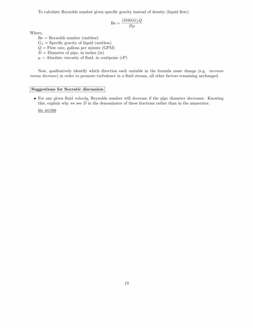
To calculate Reynolds number given specific gravity instead of density (liquid flow):
Re =(3160)GfQ
Dµ
Where,Re = Reynolds number (unitless)Gf = Specific gravity of liquid (unitless)Q = Flow rate, gallons per minute (GPM)D = Diameter of pipe, in inches (in)µ = Absolute viscosity of fluid, in centipoise (cP)
Now, qualitatively identify which direction each variable in the formula must change (e.g. increase
versus decrease) in order to promote turbulence in a fluid stream, all other factors remaining unchanged.
Suggestions for Socratic discussion
• For any given fluid velocity, Reynolds number will decrease if the pipe diameter decreases. Knowingthis, explain why we see D in the denominator of these fractions rather than in the numerator.
file i01299
13
Question 20
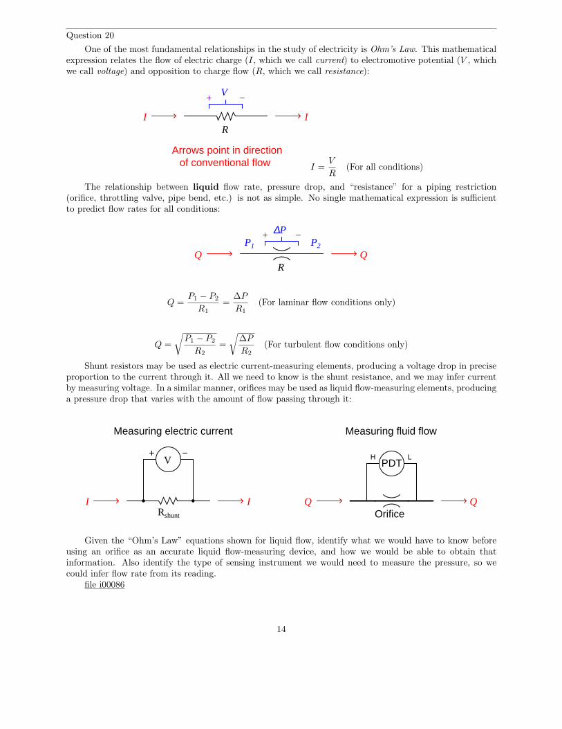
One of the most fundamental relationships in the study of electricity is Ohm’s Law. This mathematicalexpression relates the flow of electric charge (I, which we call current) to electromotive potential (V , whichwe call voltage) and opposition to charge flow (R, which we call resistance):
V
IIR
Arrows point in directionof conventional flow I =
V
R(For all conditions)
The relationship between liquid flow rate, pressure drop, and “resistance” for a piping restriction(orifice, throttling valve, pipe bend, etc.) is not as simple. No single mathematical expression is sufficientto predict flow rates for all conditions:
R
∆P
Q QP1 P2
Q =P1 − P2
R1
=∆P
R1
(For laminar flow conditions only)
Q =
√
P1 − P2
R2
=
√
∆P
R2
(For turbulent flow conditions only)
Shunt resistors may be used as electric current-measuring elements, producing a voltage drop in preciseproportion to the current through it. All we need to know is the shunt resistance, and we may infer currentby measuring voltage. In a similar manner, orifices may be used as liquid flow-measuring elements, producinga pressure drop that varies with the amount of flow passing through it:
II
V
Rshunt
Q Q
PDT
Orifice
H L
Measuring electric current Measuring fluid flow
Given the “Ohm’s Law” equations shown for liquid flow, identify what we would have to know beforeusing an orifice as an accurate liquid flow-measuring device, and how we would be able to obtain thatinformation. Also identify the type of sensing instrument we would need to measure the pressure, so wecould infer flow rate from its reading.
file i00086
14
Question 21
One of the most fundamental relationships in the study of electricity is Ohm’s Law. This mathematicalexpression relates the flow of electric charge (I, which we call current) to electromotive potential (V , whichwe call voltage) and opposition to charge flow (R, which we call resistance):
V
IIR
Arrows point in directionof conventional flow I =
V
R(For all conditions)
The relationship between gas flow rate, pressure drop, and “resistance” for a piping restriction (orifice,throttling valve, pipe bend, etc.) is not as simple. No single mathematical expression is sufficient to predictflow rates for all conditions:
R
∆P
Q QP1 P2
Q =P1 − P2
R1
=∆P
R1
Subsonic velocity with small ∆P
Q =
√
P1 − P2
R2
=
√
∆P
R2
Subsonic velocity with moderate ∆P
Q =
√
P2(P1 − P2)
R3
= Subsonic velocity with large ∆P
Shunt resistors may be used as electric current-measuring elements, producing a voltage drop in preciseproportion to the current through it. All we need to know is the shunt resistance, and we may infer currentby measuring voltage. In a similar manner, orifices may be used as gas flow-measuring elements, producinga pressure drop that varies with the amount of flow passing through it:
II
V
Rshunt
Q Q
PDT
Orifice
H L
Measuring electric current Measuring fluid flow
Given the “Ohm’s Law” equations shown for gas flow, identify what we would have to know before usingan orifice as an accurate gas flow-measuring device, and how we would be able to obtain that information.
15
Also identify the type of sensing instrument(s) we would need to measure the pressure, so we could inferflow rate from its reading.
file i00087
Question 22
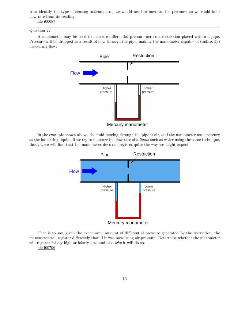
A manometer may be used to measure differential pressure across a restriction placed within a pipe.Pressure will be dropped as a result of flow through the pipe, making the manometer capable of (indirectly)measuring flow:
Flow
Higherpressure
Lowerpressure
Mercury manometer
Pipe Restriction
In the example shown above, the fluid moving through the pipe is air, and the manometer uses mercuryas the indicating liquid. If we try to measure the flow rate of a liquid such as water using the same technique,though, we will find that the manometer does not register quite the way we might expect:
Higherpressure
Lowerpressure
Mercury manometer
Pipe Restriction
Flow
That is to say, given the exact same amount of differential pressure generated by the restriction, themanometer will register differently than if it was measuring air pressure. Determine whether the manometerwill register falsely high or falsely low, and also why it will do so.
file i00796
16
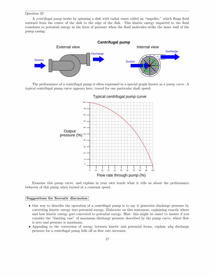
Question 23
A centrifugal pump works by spinning a disk with radial vanes called an “impeller,” which flings fluidoutward from the center of the disk to the edge of the disk. This kinetic energy imparted to the fluidtranslates to potential energy in the form of pressure when the fluid molecules strike the inner wall of thepump casing:
Centrifugal pump
Suction
Discharge
External view
Suction
DischargeInternal view
The performance of a centrifugal pump is often expressed in a special graph known as a pump curve. Atypical centrifugal pump curve appears here, traced for one particular shaft speed:
0
10
20
30
40
50
60
70
80
90
100
0 10 20 30 40 50 60 70 80 90 100
Outputpressure (%)
Flow rate through pump (%)
Typical centrifugal pump curve
Examine this pump curve, and explain in your own words what it tells us about the performancebehavior of this pump when turned at a constant speed.
Suggestions for Socratic discussion
• One way to describe the operation of a centrifugal pump is to say it generates discharge pressure byconverting kinetic energy into potential energy. Elaborate on this statement, explaining exactly whereand how kinetic energy gets converted to potential energy. Hint: this might be easier to answer if youconsider the “limiting case” of maximum discharge pressure described by the pump curve, where flowis zero and pressure is maximum.
• Appealing to the conversion of energy between kinetic and potential forms, explain why dischargepressure for a centrifugal pump falls off as flow rate increases.
17
• The pump curve shown assumes a constant rotational speed for the pump’s impeller. How would thepump curve be modified if the pump were rotated at a slower speed?
file i01407
18
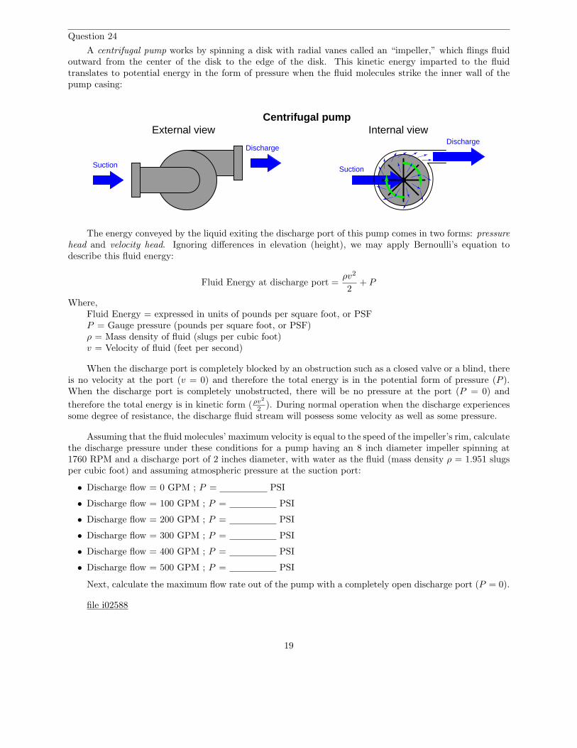
Question 24
A centrifugal pump works by spinning a disk with radial vanes called an “impeller,” which flings fluidoutward from the center of the disk to the edge of the disk. This kinetic energy imparted to the fluidtranslates to potential energy in the form of pressure when the fluid molecules strike the inner wall of thepump casing:
Centrifugal pump
Suction
Discharge
External view
Suction
DischargeInternal view
The energy conveyed by the liquid exiting the discharge port of this pump comes in two forms: pressure
head and velocity head. Ignoring differences in elevation (height), we may apply Bernoulli’s equation todescribe this fluid energy:
Fluid Energy at discharge port =ρv2
2+ P
Where,Fluid Energy = expressed in units of pounds per square foot, or PSFP = Gauge pressure (pounds per square foot, or PSF)ρ = Mass density of fluid (slugs per cubic foot)v = Velocity of fluid (feet per second)
When the discharge port is completely blocked by an obstruction such as a closed valve or a blind, thereis no velocity at the port (v = 0) and therefore the total energy is in the potential form of pressure (P ).When the discharge port is completely unobstructed, there will be no pressure at the port (P = 0) and
therefore the total energy is in kinetic form (ρv2
2). During normal operation when the discharge experiences
some degree of resistance, the discharge fluid stream will possess some velocity as well as some pressure.
Assuming that the fluid molecules’ maximum velocity is equal to the speed of the impeller’s rim, calculatethe discharge pressure under these conditions for a pump having an 8 inch diameter impeller spinning at1760 RPM and a discharge port of 2 inches diameter, with water as the fluid (mass density ρ = 1.951 slugsper cubic foot) and assuming atmospheric pressure at the suction port:
• Discharge flow = 0 GPM ; P = PSI
• Discharge flow = 100 GPM ; P = PSI
• Discharge flow = 200 GPM ; P = PSI
• Discharge flow = 300 GPM ; P = PSI
• Discharge flow = 400 GPM ; P = PSI
• Discharge flow = 500 GPM ; P = PSI
Next, calculate the maximum flow rate out of the pump with a completely open discharge port (P = 0).
file i02588
19
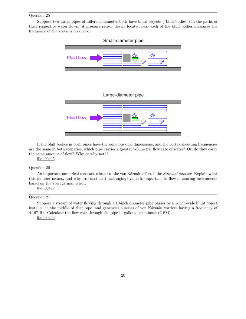
Question 25
Suppose two water pipes of different diameter both have blunt objects (“bluff bodies”) in the paths oftheir respective water flows. A pressure sensor device located near each of the bluff bodies measures thefrequency of the vortices produced:
Fluid flow
Fluid flow
Small-diameter pipe
Large-diameter pipe
sensor
sensor
If the bluff bodies in both pipes have the same physical dimensions, and the vortex shedding frequenciesare the same in both scenarios, which pipe carries a greater volumetric flow rate of water? Or, do they carrythe same amount of flow? Why or why not??
file i00495
Question 26
An important numerical constant related to the von Karman effect is the Strouhal number. Explain whatthis number means, and why its constant (unchanging) value is important to flow-measuring instrumentsbased on the von Karman effect.
file i00492
Question 27
Suppose a stream of water flowing through a 10-inch diameter pipe passes by a 1-inch-wide blunt objectinstalled in the middle of that pipe, and generates a series of von Karman vortices having a frequency of4.167 Hz. Calculate the flow rate through the pipe in gallons per minute (GPM).
file i00493
20
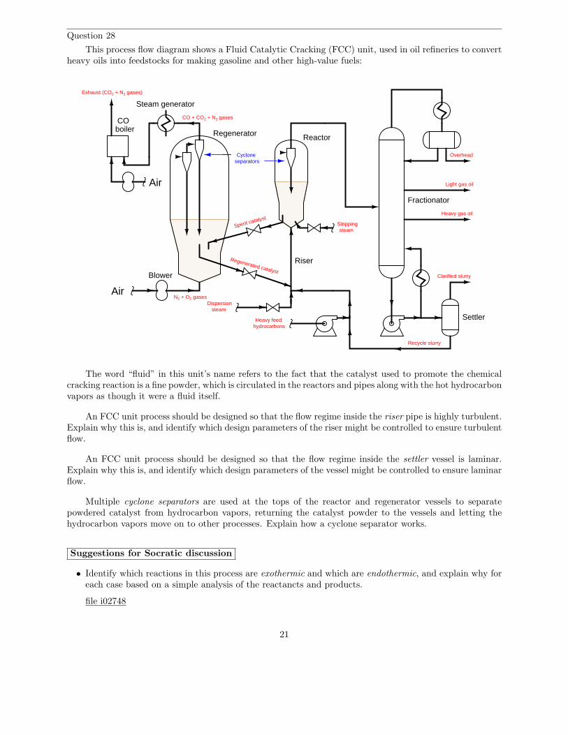
Question 28
This process flow diagram shows a Fluid Catalytic Cracking (FCC) unit, used in oil refineries to convertheavy oils into feedstocks for making gasoline and other high-value fuels:
Dispersionsteam
Regenerator Reactor
Cycloneseparators
Strippingsteam
Air
Blower
RiserRegenerated catalyst
Spent catalyst
Light gas oil
Heavy gas oil
Overhead
Settler
Clarified slurry
Heavy feed
Fractionator
Air
COboiler
Steam generator
Recycle slurry
hydrocarbons
N2 + O2 gases
CO + CO2 + N2 gases
Exhaust (CO2 + N2 gases)
The word “fluid” in this unit’s name refers to the fact that the catalyst used to promote the chemicalcracking reaction is a fine powder, which is circulated in the reactors and pipes along with the hot hydrocarbonvapors as though it were a fluid itself.
An FCC unit process should be designed so that the flow regime inside the riser pipe is highly turbulent.Explain why this is, and identify which design parameters of the riser might be controlled to ensure turbulentflow.
An FCC unit process should be designed so that the flow regime inside the settler vessel is laminar.Explain why this is, and identify which design parameters of the vessel might be controlled to ensure laminarflow.
Multiple cyclone separators are used at the tops of the reactor and regenerator vessels to separatepowdered catalyst from hydrocarbon vapors, returning the catalyst powder to the vessels and letting thehydrocarbon vapors move on to other processes. Explain how a cyclone separator works.
Suggestions for Socratic discussion
• Identify which reactions in this process are exothermic and which are endothermic, and explain why foreach case based on a simple analysis of the reactancts and products.
file i02748
21
Answers
Answer 1
The Continuity equation relates volumetric flow rate to pipe area and average velocity, assuming aconstant fluid density:
Q = A1v1 = A2v2
Given the same flow rate in both sections of pipe, the relationship between pipe area and velocity is assuch:
v2
v1
=A1
A2
Since area is proportional to the square of the diameter (or radius), we may express the ratio of velocitiesas a ratio of squared diameters:
v2
v1
=
(
d1
d2
)2
This being the case, we may solve for the velocity in the narrower section of pipe:
v2 = v1
(
d1
d2
)2
v2 = 5 ft/s
(
8 in
3 in
)2
= 35.56 ft/s
22
Answer 2
The volumetric flow rate for any fluid is equal to the flow velocity (v) multiplied by the cross-sectionalarea of the pipe (A):
Q = Av
We already know the velocity, so what we need to do now is calculate the pipe’s flowing area. The pipe’sinternal diameter of 7.92 inches gives us this cross-sectional area:
A = πr2
A = π
(
7.92
2
)2
= 49.27 in2
Converting the velocity into units of inches per minute before multiplying will give us a flow rate incubic inches per minute:
(
14 ft
s
)(
12 in
1 ft
)(
60 s
1 min
)
= 10080 in/min
Calculating volumetric flow rate:
Q = Av
Q = (49.27 in2)(10080 in/min) = 496593 in3/min
Converting volumetric flow rate units:
(
496593 in3
min
)(
1 gal
231 in3
)
= 2149.8 GPM
(
2149.8 gal
min
)(
1 bbl
42 gal
)(
60 min
1 hr
)(
24 hr
1 day
)
= 73706 bbl/day
23
Answer 3
The volumetric flow rate for any fluid is equal to the flow velocity (v) multiplied by the cross-sectionalarea of the pipe (A):
Q = Av
We already know the velocity, so what we need to do now is calculate the pipe’s flowing area. The pipe’sinternal diameter of 5.95 inches gives us this cross-sectional area:
A = πr2
A = π
(
5.95
2
)2
= 27.81 in2
Converting the velocity into units of inches per minute before multiplying will give us a flow rate incubic inches per minute:
(
10 ft
s
)(
12 in
1 ft
)(
60 s
1 min
)
= 7200 in/min
Calculating volumetric flow rate:
Q = Av
Q = (27.81 in2)(7200 in/min) = 200196.4 in3/min
Converting volumetric flow rate units:
(
200196.4 in3
min
)(
1 gal
231 in3
)
= 866.7 GPM
(
866.7 gal
min
)(
1 bbl
42 gal
)(
60 min
1 hr
)(
24 hr
1 day
)
= 29713.8 bbl/day
24
Answer 4
The Continuity equation relates volumetric flow rate to pipe area and average velocity, assuming aconstant fluid density:
Q = Av
Velocity may be determined by manipulating this equation and plugging in the known quantities in theproper units:
v =Q
A
First, we need to convert the flow rate into units of cubic inches per minute, and calculate area in squareinches:
Q =
(
180 gal
min
) (
231 in3
1 gal
)
= 41580 in3/min
A = πr2 = π(3 in)2 = 28.27 in2
Now we may calculate average velocity:
v =Q
A=
41580 in3/min
28.27 in2= 1470.6 in/min
Answer 5
P = 1373.5 lb/ft2 = 9.538 PSI
25
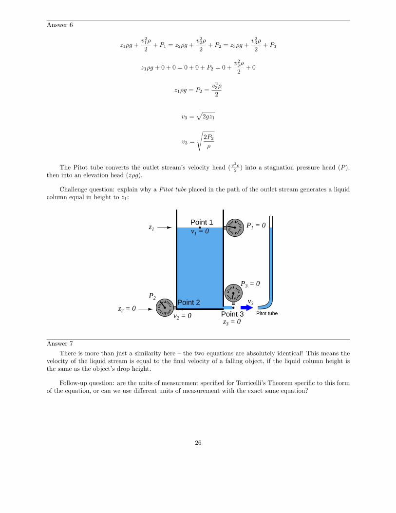
Answer 6
z1ρg +v2
1ρ
2+ P1 = z2ρg +
v2
2ρ
2+ P2 = z3ρg +
v2
3ρ
2+ P3
z1ρg + 0 + 0 = 0 + 0 + P2 = 0 +v2
3ρ
2+ 0
z1ρg = P2 =v2
3ρ
2
v3 =√
2gz1
v3 =
√
2P2
ρ
The Pitot tube converts the outlet stream’s velocity head (v2ρ2
) into a stagnation pressure head (P ),then into an elevation head (zρg).
Challenge question: explain why a Pitot tube placed in the path of the outlet stream generates a liquidcolumn equal in height to z1:
P2
P1 = 0z1
z2 = 0
Point 1
P3 = 0
Point 2
Point 3
v3
v2 = 0
v1 = 0
z3 = 0Pitot tube
Answer 7
There is more than just a similarity here – the two equations are absolutely identical! This means thevelocity of the liquid stream is equal to the final velocity of a falling object, if the liquid column height isthe same as the object’s drop height.
Follow-up question: are the units of measurement specified for Torricelli’s Theorem specific to this formof the equation, or can we use different units of measurement with the exact same equation?
26
Answer 8
In order to combine these two formulae together, we need to identify the common variable. In this case,it is height. Note that g is not really a variable, but rather a constant so long as the location is on the surfaceof planet Earth.
Now that we know what the common variable is, we may manipulate the hydrostatic pressure formulato solve for that variable, so that we will have something to substitute into Torricelli’s Theorem and finallyhave an formula solving for velocity (v) in terms of pressure (P ):
P = ρgh
h =P
ρg
v =√
2gh
v =
√
2g
(
P
ρg
)
v =
√
2
(
P
ρ
)
v =
√
2P
ρ
(Alternatively . . .)
v =√
2
√
P
ρ
Note that P actually refers to the amount of differential pressure across the opening, since Torricelli’sTheorem assumes a discharge into atmospheric pressure as well as a vented tank (atmospheric pressure ontop of the liquid).
27
Answer 9
P2 = 473.7 lb/ft2
It is tempting to alter Bernoulli’s Equation to handle measurements in inches rather than feet (especiallythe annoying unit of pressure measurement: pounds per square foot, rather than PSI). However, cautionmust be exercised when attempting this, because there is more to it than simply converting feet into inchesevery place you see “ft” in the equation.
z1ρg +v2
1ρ
2+ P1 = z2ρg +
v2
2ρ
2+ P2
There is the unit of “feet” lurking inside the unit of “slugs” which must also be accounted for. Here isthe standard weight-mass-gravity equation relating slugs to pounds:
W = mg
[lb] = [slug]
[
ft
s2
]
If we re-write the unit analysis equation to show slugs as a compound unit, we see that “feet” lurkswithin:
[lb] =
[
lb · s2
ft
] [
ft
s2
]
Thus, expressing g in inches per second squared would require us to invent a new unit of mass (lb · s2
per in) instead of slugs (lb · s2 per ft).
Answer 10
P2 = 17,792 lb/ft2 = 123.6 PSI
Answer 11
P1 = 296.77 PSI P2 = 293.27 PSI
Bernoulli’s equation assumes no gain or loss of energy between the two locations compared, and so itcannot be used to contrast the pump’s suction and discharge pressures. The pump is a machine that addsenergy to the fluid going through it, and so the assumption of equal (total) energy between the incomingand outgoing flow streams is not correct.
Answer 12
Pout = 51.32 PSI
Note: with a pipe diameter ratio of 4:1 (out:in), the exit velocity will be 16 times slower than the inletvelocity (1:4)2 = (1:16).
Answer 13
v2 = 16.57 ft/s
Note that the two pressures are given in units of PSI (not pounds per square foot), and that the twoheights are given in inches instead of feet. Also, ρbenzene = 1.753 slugs/ft3.
28
Answer 14
Bernoulli’s equation:
z1ρg +v2
1ρ
2+ P1 = z2ρg +
v2
2ρ
2+ P2
Assuming no change in height (z) is involved:
v2
1ρ
2+ P1 =
v2
2ρ
2+ P2
Knowing that P1 is the static pressure and that P2 is equal to Pstatic + Pstagnation:
v2
1ρ
2+ Pstatic =
v2
2ρ
2+ Pstatic + Pstagnation
v2
1ρ
2=
v2
2ρ
2+ Pstagnation
Knowing that v2 is zero at the stagnation point:
v2
1ρ
2= Pstagnation
Therefore, Pstagnation = 1
2v2ρ
Answer 15
P at 50 MPH = 1.215 inches H2O
P at 100 MPH = 4.859 inches H2O
Answer 16
∆P at 50 MPH = 18.22 ”W.C.
∆P at 100 MPH = 72.88 ”W.C.
29
Answer 17
Assuming no difference in height (z):
v2
1ρ
2+ P1 =
v2
2ρ
2+ P2
P1 − P2 =v2
2ρ
2−
v2
1ρ
2
∆P =ρ
2
(
v2
2− v2
1
)
2∆P
ρ= v2
2− v2
1
If Q = Av then v =Q
A
2∆P
ρ=
(
Q
A2
)2
−
(
Q
A1
)2
2∆P
ρ=
Q2
A2
2
−Q2
A2
1
2∆P
ρ=
Q2A2
1
A2
1A2
2
−Q2A2
2
A2
1A2
2
2∆P
ρ= Q2
A2
1− A2
2
A2
1A2
2
Q2 =
(
A2
1A2
2
A2
1− A2
2
)(
2∆P
ρ
)
Q =
√
A2
1A2
2
A2
1− A2
2
√
2∆P
ρ
Q =A1A2
√
A2
1− A2
2
√
2∆P
ρ
Where,Q = Volumetric flow rate (ft3/s)A1 = Large flow area (ft2)A2 = Small (throat) flow area (ft2)∆P = Differential pressure drop (lb/ft2)ρ = Mass density of fluid (slugs/ft3)
Answer 18
Q = 7550.29 GPM
If the flow rate increases beyond 7550.29 GPM, the pressure at P2 will decrease further, creating avacuum.
30
Answer 19
• Which regime creates the least amount of drag (frictional energy losses) through a long length of pipe?Laminar
• Which regime is better for mixing fluids together in a piping system? Turbulent
• Which regime is better for ensuring thorough reaction between chemical reactants in a piping system?Turbulent
• Which regime is preferable inside of a heat exchanger, to ensure maximum heat transfer? Turbulent
All other factors being equal, turbulence will be promoted by the following:
• Increasing flow rate (Q)
• Increasing fluid density (ρ or Gf )
• Decreasing pipe diameter (D)
• Decreasing viscosity (µ)
Answer 20
Here, what we do not know about the flow-measurement scenario is the flow regime (laminar orturbulent), and also what the “resistance” of the fluid restriction is. Of course, the Reynolds numberfor our flowstream will indicate its regime status, and the R factor for the orifice may be either determinedexperimentally or derived from orifice equations (available in any exhaustive reference book).
The proper pressure-sensing instrument to use for fluid flow is a differential pressure instrument, suchas a DP cell or DP gauge, or perhaps even a mercury manometer.
Answer 21
Here, what we do not know about the flow-measurement scenario is the flow regime (laminar orturbulent), and also what the “resistance” of the fluid restriction is. Of course, the Reynolds numberfor our flowstream will indicate its regime status, and the R factor for the orifice may be either determinedexperimentally or derived from orifice equations (available in any exhaustive reference book).
The proper pressure-sensing instrument to use for fluid flow is a differential pressure instrument, suchas a DP cell or DP gauge, or perhaps even a mercury manometer. In the case of large pressure drops, it mayalso be important to measure downstream pressure (P2) with reference to atmosphere.
Answer 22
The manometer will register falsely high, showing greater differential pressure than what is actuallythere. If you are having difficulty figuring this out, imagine if the liquid moving through the pipe was justas dense as the mercury within the manometer: what would that do to the mercury in the manometer givenany applied ∆P? In other words, set up a thought experiment with absurdly (simple) conditions and thenlook for patterns or trends which you may generalize for any condition.
Challenge question: derive a mathematical correction factor for interpreting the manometer’s indicationto yield true inches of mercury ∆P.
Answer 23
This graph relates pressure output versus liquid flow rate for a centrifugal-style pump operating at aconstant rotational speed.
31
Answer 24
The velocity of the fluid molecules will be equal to the rim speed of the impeller, which is thecircumference of the impeller multiplied by its rotational speed:
(
1760 rev
min
)(
8π in
rev
)
= 44233.6 in/min = 61.436 ft/s
This velocity lets us calculate the velocity head at the impeller’s rim. If we assume the water enters thepump with no pressure, this velocity head should be the only energy the water possesses at the impeller rim:
Fluid Energy at impeller rim =ρv2
2=
(1.951)(61.436)2
2= 3681.9 PSF = 25.57 PSI
This figure of 25.57 PSI will be the blocked-discharge pressure, where 100% of the fluid’s kinetic energyis translated into pressure as it finds no place to flow and its velocity stagnates to zero.
Conversely, if we imagine a situation where the discharge port is completely unblocked to achieve zerodischarge pressure, the fluid velocity exiting the port will be approximately equal to the impeller rim velocity.Applying this velocity to the Continuity equation to calculate volumetric flow at the 2-inch diameter dischargeport:
Q = Av
Q = πr2v
Q = (π)(12)(44233.6) = 138964 in3/min = 601.6 GPM
Therefore, the maximum flow rate of this pump at zero discharge pressure will be approximately 600gallons per minute.
At any flow rate between zero and maximum, the combined sum of velocity and pressure heads at thepump discharge must be equal to the maximum head at the impeller rim (3681.9 PSF equivalent). Therefore:
3681.9 =ρv2
2+ P
P = 3681.9 −ρv2
2
Using the Continuity equation to calculate discharge velocity at 100 GPM (23100 in3/min), and thenBernoulli’s equation to calculate discharge pressure:
v =Q
A=
23100
π= 7352.96 in/min = 10.21 ft/s
P = 3681.9 −(1.951)(10.212)
2= 3580.1 PSF = 24.86 PSI
32
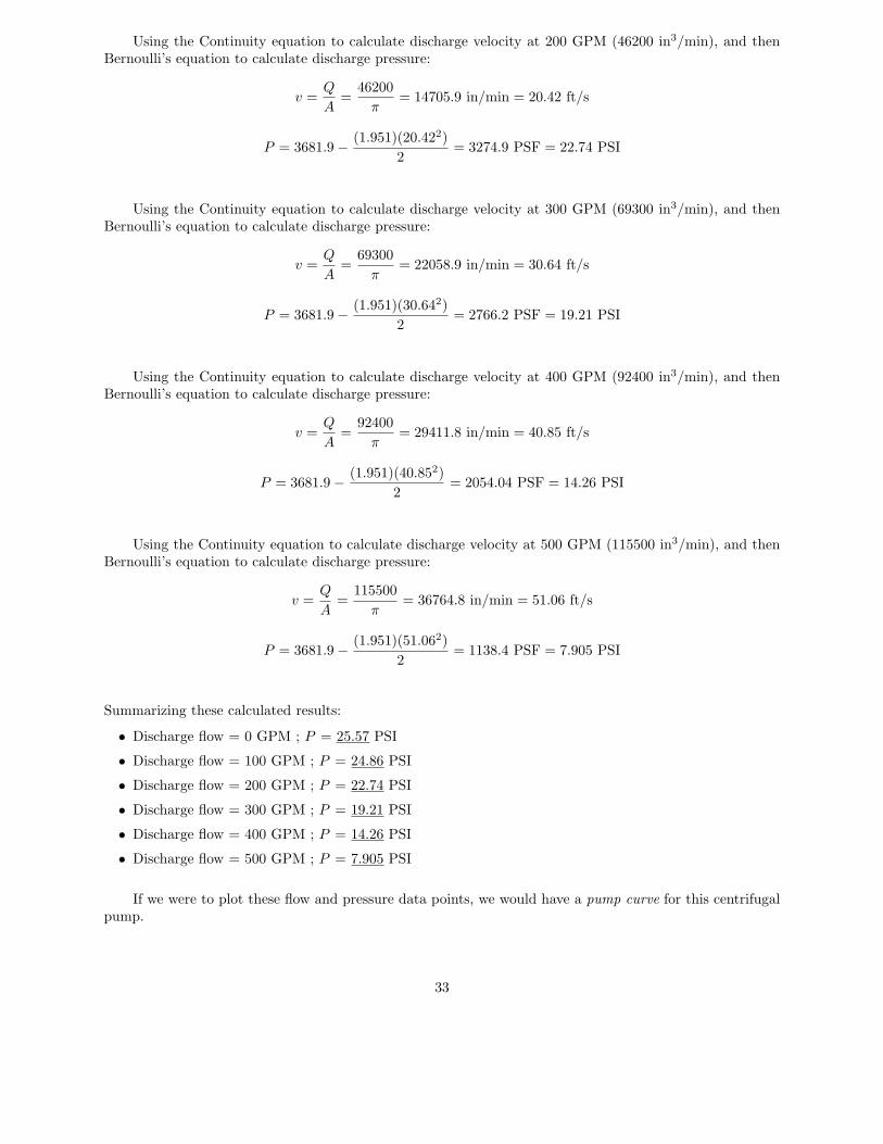
Using the Continuity equation to calculate discharge velocity at 200 GPM (46200 in3/min), and thenBernoulli’s equation to calculate discharge pressure:
v =Q
A=
46200
π= 14705.9 in/min = 20.42 ft/s
P = 3681.9 −(1.951)(20.422)
2= 3274.9 PSF = 22.74 PSI
Using the Continuity equation to calculate discharge velocity at 300 GPM (69300 in3/min), and thenBernoulli’s equation to calculate discharge pressure:
v =Q
A=
69300
π= 22058.9 in/min = 30.64 ft/s
P = 3681.9 −(1.951)(30.642)
2= 2766.2 PSF = 19.21 PSI
Using the Continuity equation to calculate discharge velocity at 400 GPM (92400 in3/min), and thenBernoulli’s equation to calculate discharge pressure:
v =Q
A=
92400
π= 29411.8 in/min = 40.85 ft/s
P = 3681.9 −(1.951)(40.852)
2= 2054.04 PSF = 14.26 PSI
Using the Continuity equation to calculate discharge velocity at 500 GPM (115500 in3/min), and thenBernoulli’s equation to calculate discharge pressure:
v =Q
A=
115500
π= 36764.8 in/min = 51.06 ft/s
P = 3681.9 −(1.951)(51.062)
2= 1138.4 PSF = 7.905 PSI
Summarizing these calculated results:
• Discharge flow = 0 GPM ; P = 25.57 PSI
• Discharge flow = 100 GPM ; P = 24.86 PSI
• Discharge flow = 200 GPM ; P = 22.74 PSI
• Discharge flow = 300 GPM ; P = 19.21 PSI
• Discharge flow = 400 GPM ; P = 14.26 PSI
• Discharge flow = 500 GPM ; P = 7.905 PSI
If we were to plot these flow and pressure data points, we would have a pump curve for this centrifugalpump.
33
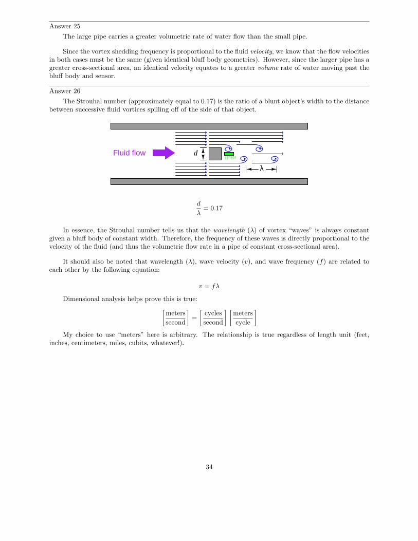
Answer 25
The large pipe carries a greater volumetric rate of water flow than the small pipe.
Since the vortex shedding frequency is proportional to the fluid velocity, we know that the flow velocitiesin both cases must be the same (given identical bluff body geometries). However, since the larger pipe has agreater cross-sectional area, an identical velocity equates to a greater volume rate of water moving past thebluff body and sensor.
Answer 26
The Strouhal number (approximately equal to 0.17) is the ratio of a blunt object’s width to the distancebetween successive fluid vortices spilling off of the side of that object.
Fluid flowsensor
d
λ
d
λ= 0.17
In essence, the Strouhal number tells us that the wavelength (λ) of vortex “waves” is always constantgiven a bluff body of constant width. Therefore, the frequency of these waves is directly proportional to thevelocity of the fluid (and thus the volumetric flow rate in a pipe of constant cross-sectional area).
It should also be noted that wavelength (λ), wave velocity (v), and wave frequency (f) are related toeach other by the following equation:
v = fλ
Dimensional analysis helps prove this is true:
[
meters
second
]
=
[
cycles
second
] [
meters
cycle
]
My choice to use “meters” here is arbitrary. The relationship is true regardless of length unit (feet,inches, centimeters, miles, cubits, whatever!).
34
Answer 27
Q = 500.04 GPM
We may derive an exact formula by using a proportionality factor (k) and the specific set of values usedto answer the quantitative question. We know that flow rate will be proportional to the product of frequency,bluff body width, and the square of pipe diameter1:
Q ∝ fwD2
We may express this as an exact equation by adding a factor k:
Q = kfwD2
Solving for k:
k =Q
fwD2
k =500.04
(4.167)(1)(10)2= 1.2
Therefore,
Q = 1.2fwD2
Where,Q = Flow rate, in gallons per minute (GPM)f = Vortex shedding frequency, in Hertz (Hz)w = Bluff body width, in inches (in)D = Diameter of pipe, in inches (in)
One really neat advantage of calculating k in this manner is that it incorporates all the necessary unitconversions performed in the original solution of Q = 500.04 GPM. Now, all we do is enter f in Hertz, w ininches, and D in inches, and we automatically get an answer for Q in units of gallons per minute.
Answer 28
Turbulence in the riser is desirable to ensure thorough mixing of all the reactants, to expedite thecracking reaction. High flow rates and a narrow pipe ensure the necessary turbulence.
Laminar flow is desirable inside the settler, to allow catalyst powder to settle to the bottom and be sentback to the reactor rather than be carried off to another processing unit. Large cross-sectional area for theflowing slurry ensures the flow will drop to a laminar regime once inside the settler vessel.
Cyclone separators introduce the incoming flow tangential to the circumference of the separator, lettingcentrifugal force pin solid particles to the separator wall. This causes the particles to lose kinetic energy andfall out the bottom of the separator.
1 Using qualitative analysis, we can tell that Q increases proportionally with increases in f and withincreases in w. We can also tell that Q increases proportionally with the square of increases in D. Justimagine doubling each of these variables, one at a time (while holding the others constant) and determinethe effect on Q.
35


![L-14 Fluids [3] Fluids at rest Fluids at rest Why things float Archimedes’ Principle Fluids in Motion Fluid Dynamics Fluids in Motion Fluid Dynamics.](https://static.fdocuments.in/doc/165x107/56649d845503460f94a6ab30/l-14-fluids-3-fluids-at-rest-fluids-at-rest-why-things-float-archimedes.jpg)


