Dynamic Femtocell Resource Allocation for Managing Inter-Tier Interference...
23
1 Dynamic Femtocell Resource Allocation for Managing Inter-Tier Interference in Downlink of Heterogeneous Networks Arsalan Saeed, Efstathios Katranaras, Mehrdad Dianati, and Muhammad Ali Imran Institute for Communication Systems (ICS), home of the 5G Innovation Centre University of Surrey, United Kingdom Email: {arsalan.saeed, efstathios.katranaras, m.dianati, m.imran}@surrey.ac.uk Abstract This paper investigates the downlink resource allocation problem in Orthogonal Frequency Division Multiple Access (OFDMA) Heterogeneous Networks (HetNets) consisting of macrocells and femtocells sharing the same frequency band. The focus is to devise optimised policies for femtocells’ access to the shared spectrum, in terms of femtocell transmissions, in order to maximise femto users sum data rate while ensuring that certain level of quality of service (QoS) for the macro-cell users in the vicinity of femtocells is provided. The optimal solution to this problem is obtained by employing the well-known Dual Lagrangian method and the optimal femtocell transmit power and resource allocation solution is derived in detail. However, the optimal solution introduces high computational complexity and may not be feasible to apply in real-time systems. To this end, we propose a heuristic solution to the problem. The algorithms to implement both optimal and efficient suboptimal schemes in a practical system are also given in detail while their complexity is compared. Simulation results show that our proposed dynamic resource allocation scheme a) ensures the macro users QoS requirements compared to the Reuse-1 scheme, where femtocells are allowed to transmit at full power and bandwidth; b) can maintain femto user data rates at high levels, compared to the Orthogonal Frequency Reuse scheme, where the network bandwidth resources are partially divided amongst macro and femtocells; and c) provides performance close to the optimal solution, while introducing much lower complexity. Index Terms Heterogeneous Networks, Femtocells, Inter-cell Interference, Resource Allocation, Binary Integer Linear Pro- gramming, Dual Lagrangian Problem. August 11, 2015 DRAFT
Transcript of Dynamic Femtocell Resource Allocation for Managing Inter-Tier Interference...

1
Dynamic Femtocell Resource Allocation for
Managing Inter-Tier Interference in Downlink
of Heterogeneous NetworksArsalan Saeed, Efstathios Katranaras, Mehrdad Dianati, and Muhammad Ali Imran
Institute for Communication Systems (ICS), home of the 5G Innovation Centre
University of Surrey, United Kingdom
Email: arsalan.saeed, efstathios.katranaras, m.dianati, [email protected]
Abstract
This paper investigates the downlink resource allocation problem in Orthogonal Frequency Division Multiple
Access (OFDMA) Heterogeneous Networks (HetNets) consisting of macrocells and femtocells sharing the same
frequency band. The focus is to devise optimised policies for femtocells’ access to the shared spectrum, in terms
of femtocell transmissions, in order to maximise femto users sum data rate while ensuring that certain level of
quality of service (QoS) for the macro-cell users in the vicinity of femtocells is provided. The optimal solution to this
problem is obtained by employing the well-known Dual Lagrangian method and the optimal femtocell transmit power
and resource allocation solution is derived in detail. However, the optimal solution introduces high computational
complexity and may not be feasible to apply in real-time systems. To this end, we propose a heuristic solution to
the problem. The algorithms to implement both optimal and efficient suboptimal schemes in a practical system are
also given in detail while their complexity is compared. Simulation results show that our proposed dynamic resource
allocation scheme a) ensures the macro users QoS requirements compared to the Reuse-1 scheme, where femtocells
are allowed to transmit at full power and bandwidth; b) can maintain femto user data rates at high levels, compared
to the Orthogonal Frequency Reuse scheme, where the networkbandwidth resources are partially divided amongst
macro and femtocells; and c) provides performance close to the optimal solution, while introducing much lower
complexity.
Index Terms
Heterogeneous Networks, Femtocells, Inter-cell Interference, Resource Allocation, Binary Integer Linear Pro-
gramming, Dual Lagrangian Problem.
August 11, 2015 DRAFT
2
I. I NTRODUCTION
Heterogeneous Networks (HetNets) comprising macro cells and densely deployed small cells are considered as
a promising solution for future 5G networks [1]. It is indicated in [2] that dense deployment of Femto Access
Points (FAPs)1 can provide higher spectral efficiency, as compared to WiFi offloading. However, mass deployment
of small cells overlayed within the area of larger cells raises challenges regarding their joint operation. FAPs can
usually operate in two modes: Open Subscriber Group (OSG) and Closed Subscriber Group (CSG). OSG FAPs are
deployed and owned by the network operator and operate as open cells to serve macrocell users in HotSpots or near
the edges of the cells. This type of FAPs are simple to manage and have demonstrated to improve access network
capacity [3]. CSG FAPs are typically owned by the subscriberand are open only to a long term managed list of
users. On the other hand, CSG FAPs are easy to manage if they are operated in a separate licence free band similar
to Wi-Fi. However, these FAPs, serving indoor subscribers as part of the operators network, need to be operated in
a licensed band. Since the licensed spectrum resources are expensive and scarce, operators prefer to deploy these
FAPs under the so-called co-channel deployment, i.e. by spatially reusing the available spectrum. As a trade-off,
this sharing of the frequency band amongst the macrocell andCSG FAPs increases Inter-cell Interference (ICI)
within the network which, if left unmanaged, may significantly deteriorate overall network performance [4]. This
highlights the need for introduction of efficient low-complexity radio resource management techniques which can
be implemented in practical systems.
A. Related Work
ICI problem has been widely discussed in literature, with focus initially targeted at homogeneous2 macrocell
scenarios. The simplest downlink frequency allocation technique is to share the whole available frequency band
amongst multiple transmission nodes. This so-called Reuse-1 technique has the highest spectrum usage but also
results in severe ICI experienced amongst the neighbouringcells. To reduce ICI, Fractional Frequency Reuse
(FFR) schemes were initially introduced [5]. However FFR schemes reduce the spectrum usage and are mostly
preplanned in nature, prohibiting adaptive frequency allocation to system dynamics. More recently, Dynamic
Fractional Frequency Reuse (D-FFR) techniques have been introduced. In [6], a central broker is considered which
constantly updates users into groups, based on their signalstrength. These groups are assigned sub-carriers which
are further used to serve the users in each group. This schemeemploys low spatial reuse, hence reducing the overall
throughput of the network. In [7], a dynamic graph based FFR scheme is discussed where neighbouring macrocells
are assigned orthogonal chunks of spectrum based on the loadon each cell. This approach results in a greedy and
low spatial reuse, especially when heavily loaded cells require high number of Resource Blocks (RBs). Another
approach for dynamic FFR is discussed in [8], where each cellaims to minimise its transmit power on each RB.
This leads to each cell utilising only the RBs with best channel quality (least interference) to serve its users. A
similar approach is shown in [9], where neighbouring nodes notify each other about their RB usage, so that they
1We interchangeably use the terms femtocell node and FAP in this work.
2By homogeneous networks, we indicate the networks with samesize and same access technology cells.
August 11, 2015 DRAFT
3
avoid assigning high transmission power in those RBs. A two step solution approach is proposed in this work:
Dynamic Frequency Planning (DFP) takes places in the first step to distribute chunks of frequency bands to the
participant sharing macrocells; at the next step, a resource allocation algorithm is proposed to take place within each
macrocell. Furthermore, the authors in [10] and [11] apply the aforementioned concept of minimising transmission
power and discuss the use of interference tolerance estimation 3 for performing resource allocation in homogeneous
macrocell and femtocell deployments, respectively.
The aforementioned techniques, being only designed for homogeneous scenarios, cannot perfectly fit to networks
with underlaid macrocells and overlaid densely deployed small cells; the reason is that the dominant interferers for
a user in the homogeneous scenario are limited and usually not as strong as in the dense HetNet scenario. Thus,
focusing on the HetNet scenario and on the femto-femto interference, [12] suggests that FAPs should serve their
users on RBs with the least measured pilot signal strength from neighbouring FAPs (hence the least femto-femto
interference). Similarly, [13] proposes a technique whereFAPs assign the top best RBs to their users and adjust
their transmit power subject to FAP users QoS constraints.
Although femto-femto interference is a notable aspect in HetNet scenario, the degradation of performance for
macrocell served users due to interference caused from FAPsto macrocell users will be more critical than in case
of FAP users; since there are fewer users served by FAPs as compared to macrocells, FAP served users are anyway
allocated with more bandwidth resources. Thus, regarding the interference from FAPs to macrocell users, [14]
presents a bandwidth partitioning amongst macrocells and FAPs, where FAPs are not allowed to transmit in the
bandwidth assigned to a macrocell, hence, reducing the spatial reuse. In [15], authors elaborate on the presence of
CSG FAPs further elevating the issue of ICI as compared to public FAPs and discuss the use of shared, separate
and partially shared bandwidth for this case. Furthermore [16] suggests the use of higher level modulation and
coding schemes for indoor femtocells as their users generally realise good signal strengths. In [17], a scheme is
proposed which zones FAP served users for either link adoption or requirement of orthogonal sub-bands and a
central entity assigns the users with separate subbands from a pool. Finally, in [18], a mathematical framework is
presented to minimise the interference from FAPs to macrocells. FAPs are allowed to transmit on certain RBs based
on the calculated distance between the FAPs and neighbouring macrocells. However, for enhanced performance FAP
muting decisions should be more adaptive to the system dynamics and consider the presence of macrocell served
users in the vicinity of FAPs. To the best of our knowledge there is no such analysis in literature based on the idea
of interference tolerance estimation in heterogeneous networks where FAPs pose interference to macrocell users.
Authors in [10], [11] have applied the concept of interference tolerance estimation but only in case of homogeneous
networks. This is a notable shortcoming, as macro victim users trapped in the vicinity of CSG FAPs suffer from
severe interference [15].
3Sum of interference signal that a user can tolerate from neighbouring interferers in order to achieve a signal strength level.
August 11, 2015 DRAFT

4
Fig. 1: Example of dynamic femtocell resource allocation for victim macro-user protection. Femtocell node A may
use the full available resources while the transmission forfemtocell node B is restricted in order to protect macrocell
user B, which is in its vicinity at that specific time instance.
B. Contributions and Overview of the Paper
In this paper, we investigate the dynamic resource allocation problem for OFDMA heterogeneous networks by
considering femto to macro inter-tier interference. Our objective is to improve the overall throughput of FAP served
users without deteriorating the macro users performance bydynamically adjusting FAP resource allocation. This is a
valid problem especially for the case where macro users happen to be in the vicinity of one or more interfering FAPs.
We consider a scenario where the FAPs and the macrocell node are allowed to reuse the entire available bandwidth;
however, in order to protect the macrocell served users fromfemtocell interference, a jointly optimised resource
allocation scheme prohibits FAPs from accessing certain RBs. The general concept of the proposed approach is
illustrated in Fig. 1.
The aforementioned problem is concisely formulated in thispaper as a femtocell users’ sum rate maximisation
problem subject to minimum macro user rate requirement constraints. These constraints are translated into a
maximum level of interference that each macro user can tolerate from all neighbouring FAPs. To determine the
optimal FAP transmit power and RB allocation, the above Mixed Integer Non-linear Programming problem is relaxed
to a computationally tractable dual problem and the well known Dual Lagrangian approach [19] is translated into this
specific case. However, the optimal solution introduces high computational complexity for implementation in real-
time systems. To this end, we consider a relaxed version of the original problem, where FAPs are either transmitting
or being muted on each RB, and propose a low-complexity heuristic scheme to solve it. The big advantages of
our proposed scheme are that: a) the optimisation problem can be solved considering the instantaneous throughput
obtained in practical systems instead of the theoretical Shannon link capacity, thus, more practical aspects of the
communication channel (such as modulation and coding scheme used) can be taken into account and evaluated;
and b) provides gains close to the optimal solution with reasonable low complexity for practical implementation,
despite the fact that power allocation per RB is kept constant. Focusing on the practical application of such dynamic
August 11, 2015 DRAFT

5
approaches, we analyse in detail how the optimal and heuristic schemes can be implemented in a real-world system
such a Long-term evolution (LTE) networks and compare theircomputational complexities. Using Monte-Carlo
simulations, we demonstrate that our proposed dynamic resource allocation scheme: a) ensures the macro users
QoS, compared to Reuse-1 scheme; b) maintains femto user data rates at high levels, compared to the Orthogonal
Frequency Reuse scheme.
The rest of this paper is organised as follows. Section II presents the system model. The mathematical formulation
of the problem as a Dual Lagrangian problem is given in section III and the optimal solution is derived. Section IV
introduces the efficient suboptimal RB allocation scheme while Section V presents the algorithms of the proposed
schemes and compares their computational complexity. Numerical results and obtained insights are discussed in
Section VI. Finally, Section VII concludes the paper.
II. SYSTEM MODEL
We consider a system ofM + 1 cells, comprising one macrocell (identified as cell0) andM femtocells within
the macrocell area. The set of femtocells is defined asM = 1, . . . ,M. We assume that there areK active users
in the system. We consider that each user can have only one serving node, but each cell can support multiple users;
thus,K , |K| = |K0 ∪K1 · · · ∪ KM |, whereK denotes the set of all users in the system andKm denotes the set
of users served by node in cellm.
Following the binary RB allocation nature of the OFDMA systems the total system bandwidth is divided inN
RBs and each RB can be allocated to only one user in each cell. Macrocell node can allocate all the available RBs to
its associatedmacro-users (MUE). Moreover, macrocell users are assumed to have minimum data rate requirements.
On the other hand, femtocell nodes reuse the same resources to serve theirfemto-users (FUE) based on a
resource allocation policy. We consider a central entity residing at the macrocell node which is able to collect
relevant information to make resource allocation decisions and guide femtocells on the resource allocation policy
to be adopted. Such a deployment could be considered semi-distributed since for a multi macrocell system their
could be a central entity present at each macrocell, guidingthe underlying femtocells.
We define binary indicator variablesφk,m,n ∈ 0, 1, whereφk,m,n = 1 when femtocellm serves itskth assigned
user in thenth RB; otherwise, the RB allocation parameters take the zero value. Thus, we can define the vector
containing all RB allocation parametersφ = [φ1,1,1 . . . φKM ,M,N ], which characterizes the femtocellsRB allocation
policy. Moreover, transmit power of themth femtocell in thenth RB is denoted bypm,n ≤ Pmax, wherePmax is
the maximum allowed transmission power of any femtocell. Vectorp = [p1,1 . . . pM,N ] characterizes the femtocells
power allocation policy.
A. User SINR and Rate Modelling
The SINR of MUE or FUE users can be modelled as follows. Using index 0 as macrocell identification, the
SINR of theuth MUE at RB n can be given by:
γu,0,n =p0,nΓ
0u,0,n
M∑
m=1
(
∑
k∈Km
φk,m,n
)
pm,nΓmu,0,n +N0B
, (1)
August 11, 2015 DRAFT

6
wherep0,n denotes the transmit power of macrocell node at RBn, Γik,m,n is the channel gain between base station
at cell i and userk being served at cellm in RB n, N0 is the noise power spectral density andB is the bandwidth
of each RB.
Similarly, the SINR of FUEk in cell m at RB n can be given by:
γk,m,n =pm,nΓ
mk,m,n
p0,nΓ0
k,m,n +
M∑
i=1
i6=m
∑
l∈Ki
φl,i,n
pi,nΓik,m,n +N0B
. (2)
The rate of each user (FUE or MUE) can be expressed by the Shannon-Hartley Theorem as follows:
Rk,m,n = B log2 (1 + γk,m,n) . (3)
It should be noted that although (3) is not a practically achievable rate, it is used as a performance indicator for
comparison purposes.
B. Maximum Interference Allowance
In this sub-section we formulate themaximum interference allowance, which is defined as the maximum amount
of interference (sum of interference from all neighbouringtransmitters) that a user can tolerate for a given minimum
data rate demand. The minimum data rate demand for a MUE can betranslated into a minimum data rate demand
at each RB, allocated to that specific MUE. Moreover, the minimum MUE demand data rate at RBn can be
translated into a specific minimum requiredγrequ,0,n SINR value [10]. Having identified the minimum SINR value
and considering (1) we can find the maximum interference power Ωmaxu,n that MUEu can tolerate in RBn from all
femtocell nodes to obtain this rate threshold:
Ωmaxn =
p0,nΓ0u,0,n
γrequ,0,n
−N0B. (4)
If the potential channel gain from any femtocellm to the MUE is denoted asΓ(m)0,u,n, the total interference caused
to it by all femtocells in each RB can be given by:
Ωsumn =
M∑
m=1
(
∑
k∈Km
φk,m,n
)
pm,nΓm0,u,n =
M∑
m=1
(
∑
k∈Km
φk,m,n
)
ωm0,u,n, (5)
whereωm0,u,n , pm,nΓ
mu,0,n can be interpreted as the interference that is caused to useru in cell 0 (macrocell) on
RB n from femtocellm.
III. O PTIMAL RESOURCEALLOCATION (ORA)
Our problem is defined as a maximisation of the sum rate of all active users in the femtocells, while: 1) the
individual rate of any MUE is ensured to be greater than a minimum value and; 2) FAP transmit power as well as
RB allocation constraints are satisfied.
The achievable sum rate of all active users in femtocells over the whole allocated system bandwidth is given by:
R =
N∑
n=1
M∑
m=1
(
∑
k∈Km
φk,m,nRk,m,n
)
, (6)
August 11, 2015 DRAFT

7
whereRk,m,n denotes the achievable rate ofkth user served by femtocellm on RBn. From equation (6), considering
also (2) and (3), it can be observed that the FUEs sum rate is a function of both femtocell RB and power allocation
policy, i.e.R = f (φ,p). In the following we formulate the respective sum rate optimisation problem and examine
its solution.
A. Problem Formulation and Solution Approach
The general sum rate optimisation problem comprising the objective function and the imposed constraints can
be formulated as follows:
maxp,φ
R (7)
subject to:
φk,m,n ∈ 0, 1 , ∀k ∈ K \ K0,m ∈ M, n; (7a)∑
k∈Km
φk,m,n ∈ 0, 1 , ∀m ∈ M, n; (7b)
Ωsumn ≤ Ωmax
n , ∀n; (7c)
N∑
n=1
(
∑
k∈Km
φk,m,n
)
pm,n ≤ Pmax, ∀m ∈ M; (7d)
pm,n ≥ 0, ∀m ∈ M, n. (7e)
Constraint (7b) indicates that RBs are exclusively allocated to one user served by each cell pair to avoid intra-cell
interference; constraint (7c) denotes the total maximum interference that a MUE served by macrocell on RBn
can tolerate from all femtocells in the macro area in order tosatisfy its minimum rate needs; finally, constraints
(7d)-(7e) stand for the maximum and minimum transmission power constraints at each femtocell node.
The optimisation problem in (7) contains both continuous4 (p) and binary (φ) decision variables and it is
categorised in general as a mixed integer nonlinear programming problem (MINP) since the objective function (R)
is nonlinear inp considering equations (2) and (3). Finding the optimal solution to these non-convex problems
requires computationally complex exhaustive search, rendering its implementation in practical systems impossible
and becomes even harder when QoS constraints are added on top(as is the case here with the minimum MUE rate
constraints). However, to make the problem tractable, we relax the resource allocation integer constraints to take any
real value between0 and1. This time-sharing condition essentially considers the time sharing of each subcarrier
in practice and it is proved in [20] that the duality gap of anyoptimisation problem satisfying the time sharing
condition is negligible as the number of subcarriers becomes sufficiently large. Therefore, our relaxed optimisation
problem of (7) can be solved optimally by using the dual method [19], [20].
4Considering that femtocells allocate power to RBs according to some predefined power levels, vectorp can instead contain integer variables.
This of course renders the optimisation problem even harderto solve.
August 11, 2015 DRAFT

8
B. Dual Method for Optimal Joint Power and RB Allocation
The dual method applied in our case will comprise the following steps [19]: a) translating the original optimisation
problem into its Lagrangian dual, associating QoS and powerconstraints with dual variables; b) decomposing the
dual problem into independently solvable subproblems by removing the coupling between RBs via Lagrangian
relaxation; c) further decomposing the subproblems through a two phase second level primal decomposition where
power and RB allocation optimisation is performed sequentially and; d) using the subgradient method to iteratively
update the dual variables in parallel until they (and essentially the original problem) converge into the optimal
values. In the following, the various steps of the dual method are presented in detail.
1) Dual Problem: The Lagrangian function of the problem in (7) can be given by:
L(φ,p,λ,µ)
=N∑
n=1
∑
m∈M
∑
k∈Km
φk,m,nRk,m,n +∑
n
λn(M∑
m=1
Ωmaxn − (
∑
k∈Km
φk,m,n)pm,nΓm0,u,n)
+∑
m
µm(Pmax −∑
n
(∑
k∈Km
φk,m,n)pm,n)
=∑
n
∑
m
∑
k∈Km
φk,m,nRk,m,n − λn(
M∑
m=1
(∑
k∈Km
φk,m,n)pm,nΓm0,u,n)−
∑
m
µm(∑
k∈Km
φk,m,n)pm,n
+∑
n
λnΩmaxn +
∑
m
µmPmax,
(8)
whereλ = [λ1, ....λN ] andµ = [µ1, ....µM ] are the dual variable vectors associated with the individual interference
constraints on MUEs and the femtocells transmit power constraint, respectively. The Lagrangian dual function can
be given as:
g(λ,µ) =
maxφ,p
L(φ,p,λ,µ),
s.t.
0 ≤ φk,m,n ≤ 1, ∀k ∈ K \ K0,m ∈ M, n;
∑
k∈Km
φk,m,n ≤ 1, ∀m ∈ M, n;
pm,n ≥ 0, ∀m ∈ M, n.
(9)
Hence, the dual optimisation problem is formulated as:
minλ,µ≥0
g(λ,µ). (10)
2) Decomposition: The coupling between RBs can be removed by Lagrangian relaxation and equation (9) can
be decomposed intoN subproblems at each RB with each subproblem given as:
August 11, 2015 DRAFT
9
maxφ,p
Ln (φn,pn) =
maxφ,p
∑
m
∑
k∈Km
φk,m,nRk,m,n
−λn
(
M∑
m=1
(
∑
k∈Km
φk,m,n
)
pm,nΓm0,u,n
)
−∑
m
µm
(
∑
k∈Km
φk,m,n
)
pm,n
s.t.
0 ≤ φk,m,n ≤ 1, ∀k ∈ K \ K0,m ∈ M, n;
∑
k∈Km
φk,m,n ≤ 1, ∀m ∈ M, n;
pm,n ≥ 0, ∀m ∈ M, n,
(11)
whereφn , [φ1,1,n . . . φk,m,n] andpn , [p1,n . . . pm,n]. This dual problem can be further decomposed through a
second level primal decomposition and solved in two phases:optimal power allocation and optimal RB allocation.
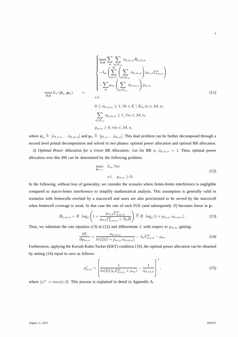
3) Optimal Power Allocation for a Given RB Allocation: Let for RB n, φk,m,n = 1. Then, optimal power
allocation over this RB can be determined by the following problem:
maxpm,n
Ln, ∀m
s.t. pm,n ≥ 0.
(12)
In the following, without loss of generality, we consider the scenario where femto-femto interference is negligible
compared to macro-femto interference to simplify mathematical analysis. This assumption is generally valid in
scenarios with femtocells overlaid by a macrocell and usersare also provisioned to be served by the macrocell
when femtocell coverage is weak. In that case the rate of eachFUE (and subsequentlyR) becomes linear inp:
Rk,m,n = B log2
(
1 +pm,nΓ
mk,m,n
p0,nΓ0k,m,n +N0B
)
∆= B log2 (1 + pm,n αk,m,n) . (13)
Thus, we substitute the rate equation (13) in (12) and differentiateL with respect topm,n, getting:
∂L
∂pm,n
=αk,m,n
ln(2)(1 + pm,n αk,m,n)− λnΓ
m0,u,n − µm. (14)
Furthermore, applying the Karush-Kuhn-Tucker (KKT) condition [19], the optimal power allocation can be obtained
by setting (14) equal to zero as follows:
p∗m,n =
1
ln(2)(λnΓm0,u,n + µm)
−1
αk,m,n
+
, (15)
where[x]+ = max[x, 0]. This process is explained in detail in Appendix A.
August 11, 2015 DRAFT

10
4) Optimal RB allocation: By eliminating the power variable in equation (12) and substituting into equation (8),
the dual function can be alternatively expressed as:
g(λ,µ) =
maxφ
∑
n
∑
m
∑
k∈Km
φk,m,nHk,m,n(λ,µ)
+∑
n
λnΩmaxn +
∑
m
µmPmax,
s.t.
0 ≤ φk,m,n ≤ 1, ∀k ∈ K \ K0,m ∈ M, n;
∑
k∈Km
φk,m,n ≤ 1, ∀m ∈ M, n
, (16)
where the functionHk,m,n(λ, µ) is given by:
Hk,m,n = log2(1 + p∗n,mαk,m,n)− λnp∗n,mΓm
0,u,n − µmp∗n,m. (17)
Here,Hk,m,n can be regarded as the potential profit or loss from femtocellm transmitting to itskth user on RB
n. Intuitively we can define the first term of the expression as the maximum achieved rate of a user if its serving
femtocell transmits on RBn, the second term as the interference penalty and the third term as the power constraint
price. Thus, the optimal RB allocation will be obtained according to the following criterion:
φ∗k,m,n =
1, k∗ = arg maxk∈Km
Hk,m,n andHk∗,m,n > 0
0, otherwise, ∀m ∈ M, n.
(18)
5) Variable Update: As the dual function in equation (9) is convex by definition, the subgradient method is
used to minimiseg(λ,µ) [19]. Thus, dual variable vectorsλ andµ are updated in parallel using the appropriate
subgradients ofg(λ,µ) at each iteration (see Appendix B):
λn(i+ 1) =
λn(i) + ψ(i)
∑
n
M∑
m=1
(∑
k∈Km
φ∗k,m,n)p
∗m,nΓ
m0,u,n −Ωmax
n
, (19)
µm(i+ 1) =
µm(i) + κ(i)
∑
n
(∑
k∈Km
φ∗k,m,n)p
∗m,n − Pmax
. (20)
where,ψ(i) andκ(i) are the diminishing step sizes andi denotes the iteration index. If the step sizes are selected
according to the diminishing step size policy [20], the subgradient method converges to the optimal dual variables,
thus, the optimal joint power and RB allocation can be computed algorithmically.
The process of the decomposed dual problem is shown in Fig. 2.It can be summarised that the dual problem
decomposition includes the following steps: the power allocation values are calculated using equation (15), which
are then replaced into equation (17) to determine the profit matrix H ; further equation (18) is used to determine
the optimal pair of power and transmitting femtocell for each RB.
August 11, 2015 DRAFT

11
Fig. 2: Dual problem decomposition flow diagram.
IV. EFFICIENT SUBOPTIMAL RB ALLOCATION (ESRA)
The computational complexity of the ORA scheme will still behigh for implementation in a real system when
the number of femtocells and users per cell grows large. To address the complexity issues of ORA scheme, we
further propose a heuristic efficient suboptimal RB allocation (ESRA) scheme. As will be shown in later sections,
the proposed ESRA scheme significantly reduces the computational complexity with minimal degradation in the
performance compared to ORA scheme. Computational complexity of ORA and ESRA schemes are further discussed
in Section V.
In order to simplify the problem in (7), we focus only on the RBallocation. To this end, we assume maximum
transmit power at femtocell nodes and equal power allocation across RBs, i.e.pm,n = Pmax
Nfor any femtocellm. In
that case, the sum rate maximisation problem is transformedinto a pure binary linear optimisation problem (BLP)
which is formulated as follows:
August 11, 2015 DRAFT

12
maxφ
N∑
n=1
M∑
m=1
(
∑
k∈Km
φk,m,nRk,m,n
)
, (21)
subject to:
φk,m,n ∈ 0, 1 , ∀m,n, k; (21a)∑
k∈Km
φk,m,n ∈ 0, 1 , ∀m,n; (21b)
M∑
m=1
(
∑
k∈Km
φk,m,n
)
pm,nΓm0,u,n ≤ Ωmax
u,n , ∀u ∈ Km, n. (21c)
The key benefit of the efficient sub-optimal RB allocation scheme is expected to come from the significant reduction
of the optimisation problem search space by considering only RB allocation. This reduces the complexity and
convergence time of the problem; hence, it can be easily solved for multiple or even every Transmission Time
Interval (TTI) in LTE networks. The computational complexity comparison for ORA and ESRA schemes is presented
in Fig. 3. It can be seen that as we increase the number of FAPs in the network, the computational complexity
increase for both the scheme. However for ESRA, this increase is relatively negligible as compare to ORA scheme.
An additional significant benefit offered by the efficient ESRA scheme, apart from the reduced complexity, is
that the optimisation problem in (21) can be solved considering the instantaneous throughput obtained in practical
OFDMA systems instead of the theoretical Shannon link capacity of (3). In general, the instantaneous throughput
of any userk served by femtocellm on RB n in OFDMA systems can be given as [10]:
Rk,m,n = BR(r) · [1− BLER(r, γk,m,n)] , (22)
where BR is the theoretical bit rate for any MCSr when there are no errors which is depended on the network
configuration, i.e. forNnSC number of data sub-carriers per RB,Nn
SY number of symbols per RB, RB’s durationT nRB
ander efficiency (in bits per symbol) of MCSr allocated to the user of interest, the BR for MCSr is given by:
BR (r) =Nn
SCNnSY
T nRB
· er . (23)
Moreover, BLER denotes the block error rate suffered by thisuser on RBn which is a function of the realised
SINR and the MCS used.
Similarly the instantaneous throughput of any MUEu served on RBn can be given as:
Ru,0,n = BR(r) · [1− BLER(r, γu,0,n)] . (24)
As discussed in the previous section, a minimum overall datarate demand for a MUE can be translated into a
minimum data rate demand at each RB. Moreover, according to equation (24), the minimum MUE demand data
rate at RBn can be translated into a specific MCS (rmin) that has to be used and a minimum requiredγrequ,0,n
SINR value. Having identified the minimum SINR value and considering equation (1) we can find the maximum
interference powerΩmaxn that MUE being served on RBn can tolerate from all femto base stations to obtain this
rate threshold.
August 11, 2015 DRAFT

13
V. A LGORITHMS AND IMPLEMENTATION
In this section, a high level description is provided on how the investigated optimal and suboptimal resource
allocation schemes can be implemented in LTE heterogeneousnetworks comprising macrocells and femtocells. The
following arguments explain how the key functions and elements of LTE architecture can be used for this reason.
A: UEs report their Channel Quality Indicator (CQI) and demand rate to their serving cells on frequent basis
which determines the user channel gain on that specific RB. Based on these reports received from MUEs,
equations (3) and (4) can be used to estimate the maximum interference,Ωmaxn , that a MUE can tolerate on
a certain RB. Note that this estimation will also decide the MCS and Transport Block (TB) size of the future
transmissions from the serving node to that UE.
B: UEs also report to their serving cell, the neighbouring cell’s Reference Signal Received Quality (RSRQ) along
with the Physical Cell ID (PCI) of the neighbouring cell. These reports are generally used for A2, A3 and
A4 measurements based handovers. In our case, the respective MUE reports can be used to estimate the top
neighbouring interfering femtocells; then, this information can be used to estimate the total interference caused
to it by all femtocells in each RB,Ωmaxn , and formulates the optimisation constraint (7c).
C: Moreover, the addition of X2 logical interface in LTE provides the means for cells to communicate. Amongst
the macrocell and the neighbouring femtocells, X2 can act asan interface to guide the neighbouring femtocells
to restrict their transmissions. Thus, X2 interface can be used to input each femtocell utility (i.e. expected rate
of FUEs in the femtocell based on equation (3)) at each RB to the central entity at the macrocell. The input
from all femtocells, formulates our objective function in (6) (i.e. expected sum rate of all FUEs in the system).
D: Finally, the optimisation process of either the optimal problem in (7) or the suboptimal problem in (21) is
performed at the central entity. The optimisation functionreturnsφk,m,n and pm,n for the optimal case and
only φk,m,n for the suboptimal case. These parameters are passed to femtocells over the X2 interface and
act as a restriction matrix for each femtocell. Furthermore, in order to avoid introducing unnecessary control
overheads into the network, restriction matrix can only be forwarded subject to change in the optimisation
parameters,φk,m,n andpm,n. In that case, femtocells continue to use the last updated restriction matrix until
a new update is passed by the central entity.
Our proposed solutions can be considered for semi-distributed implementation case of a practical multi macrocell
system i.e. a central entity could be placed at each macrocell which guides the under laying femtocells in a distributed
manner. Furthermore, spectrum sensing techniques such as wideband CQI sensing [21] could be employed for
systems with limited coordination possibilities. The following tables provide a summarising pseudocode for the
processes required at each scheme.
The time complexity of the optimal exhaustive search in our case shall beO(2(KMN)), which is exponential in
nature. However, for the ORA scheme, the complexity is mainly dependent on solving the dual problem. The number
of computations required to solve the RB allocation isK(M+1) andN number of allocations are required to solve
for all RBs. The complexity for each complete iteration isO(NK(M+1)). The total complexity of the subgradient
method is polynomial in the number of dual variable, and isO(N +M). Therefore, the overall complexity of the
August 11, 2015 DRAFT

14
Algorithm 1 ORA Scheme
1: Calculate : Ωsumu,n, Rk,m,n,Ω
maxu,n using eq (4), (5) and (13)
2: Initialize λn and µm
3: while g(λ, µ) is not converged in eq (9),do
4: Calculate : P ∗m,n in eq (15)
5: Calculate : Hk,m,n using eq (17)
6: Update : φk,m,n using eq (18)
7: If Hk,m,n > 0 then updateφk,m,n = 1, 0 otherwise
8: Calculate : g(λ, µ) using eq (16)
9: Update : λn andµm using eq (19) and (20)
10: end
11: Notify neighbouring femtocells withP ∗m,n andφk,m,n
Algorithm 2 ESRA Scheme
1: Calculate : Ωsumu,n, Rk,m,n,Ω
maxu,n using eq (4), (5) and (22)
2: [φk,m,n, Rk,m,n] = bintprog(Rk,m,n,Ωmaxu,n ,Ω
sumu,n)
3: Notify neighbouring femtocells withφk,m,n
5 10 15 20 25 300
1000
2000
3000
4000
5000
6000
7000
Number of Femtocells
Ave
rage
Num
ber
of It
erat
ions
ORA
ESRA
Fig. 3: Computational complexity comparison between ORA and ESRA scheme.
ORA scheme isO((N +M)2(NMK)). The ESRA scheme is solved by binary linear integer programming. There
are several linear programming relaxations applied to suchalgorithms, which make them very effective in practice
but it is difficult to prove theoretical complexity bounds onthe performance of such algorithms. A comparison in
terms of number of iterations between the ORA and ESRA schemeis presented in Fig. 3, emphasizing on the lower
complexity, therefore, higher the practicality of the ESRAscheme.
August 11, 2015 DRAFT

15
VI. SIMULATION RESULTS
In this section, we evaluate the performance of the dynamic resource allocation schemes in the context of a
real-world cellular network scenario. We simulate a singleLTE macrocell with a fixed number of users attached to
it and several femtocells, within the operational area of the macrocell. Macrocell serves the MUEs with a persistent
scheduling (resource allocation within the macrocell remains fixed for multiple frames). On the other hand each
femtocell has a single user attached to it, being served withthe potential to use all the available RBs. Further details
of the simulation parameters are given in Table I.
TABLE I: LTE-Based Scenario - Simulation Parameters.
Parameter Macro Femto
Number of nodes 1 5
Carrier frequency 2.1 GHz
Bandwidth 10 MHz
Node transmit power 43 dBm 23 dBm
Path loss model 128.1 + 37.6 log10 (d[Km])
Number of UEs 5 1 UE per FAP
Noise Figure at UE 9 dB
Thermal noise density −174 dBm/Hz
Cell Radius 800m 50m
In order to evaluate the average performance of the ORA and ESRA scheme, we first consider a large number
of system snapshots with uniform distribution of randomly deployed MUE and FAP nodes within the macrocell
area at each snapshot. We also compare the performance of theproposed dynamic resource allocation schemes
with the two benchmark cases: a) Reuse-1, where macrocell and FAPs transmit on all the RBs, and b) Orthogonal
Reuse, where 50% of the RBs are reserved for macrocell and theremaining 50% RBs are shared amongst FAPs.
At the second step we validate and compare in more detail, theoperation of ORA and ESRA schemes considering
deterministically placed nodes.
A. Randomly Placed Nodes
To evaluate and compare the overall performance of the proposed schemes we find the achieved MUE and FUE
rates for a large number of uniform random MUE and FAP node placement scenarios. Results are averaged for103
independent system snapshots.
Fig. 4 and 5 show the cumulative distribution function (CDF)of the achievable MUE data rates for a MUE
demand of 0.5Mbps and 1.2Mbps respectively. It can be observed that Reuse-1 scheme results into a MUE outage
(i.e. when the MUE achieved rate is below the demand rate) of 20% and 50% respectively. Orthogonal Reuse also
results into a 10% MUE outage but only at higher MUE demand rate (1.2Mbps). On the other hand, ORA and
ESRA schemes successfully eliminate MUE outage. Moreover,comparing ORA and ESRA schemes performance,
we observe that ORA scheme manages to keep the MUE achieved data rates close to the MUE demand; nearly
55% and 90% MUE achieved data rates for 0.5Mbps and 1.2Mbps MUE demand respectively. While in ESRA,
August 11, 2015 DRAFT

16
0 1 2 3 4 50
0.1
0.2
0.3
0.4
0.5
0.6
0.7
0.8
0.9
1
Data Rate (Mbps)
CD
F
ORAESRAReuse−1Orth. Reuse
Fig. 4: CDF of MUE data rates for MUE Demand of 0.5Mbps.
0 1 2 3 4 50
0.1
0.2
0.3
0.4
0.5
0.6
0.7
0.8
0.9
1
Data Rate (Mbps)
CD
F
ORAESRAReuse−1Orth. Reuse
Fig. 5: CDF of MUE data rates for MUE Demand of 1.2Mbps.
MUE rates are always above the demand. The ORA approach is beneficial to facilitate FAPs to maximize RB
usage to serve their users. This behaviour is clearly depicted in Fig. 6 and 7, where the CDF of FUE data rates is
presented for the same MUE demand rates. ORA scheme has a similar performance to that of Reuse-1, whereas
ESRA scheme slightly lags behind. It can also be observed from these latter plots that ORA and ESRA schemes
outperform Orthogonal Reuse scheme at higher percentiles in terms of achieved FUE data rates. This is due to the
fact that since FFR scheme is static in nature, the reserved bandwidth for MUEs may not be fully utilised when the
MUE demand is low. Specific numerical values supporting the aforementioned observations are presented in Table
II, where the50th and95th percentile average MUE and FUE rates are given for the various MUE demand rates.
August 11, 2015 DRAFT

17
0 5 10 15 20 25 300
0.1
0.2
0.3
0.4
0.5
0.6
0.7
0.8
0.9
1
Data Rate (Mbps)
CD
F
ORAESRAReuse−1Orth. Reuse
Fig. 6: CDF of FUE data rates for MUE Demand of 0.5Mbps.
0 5 10 15 20 25 300
0.1
0.2
0.3
0.4
0.5
0.6
0.7
0.8
0.9
1
Data Rate (Mbps)
CD
F
ORAESRAReuse−1Orth. Reuse
Fig. 7: CDF of FUE data rates for MUE Demand of 1.2Mbps.
B. Fixed Node Locations
In order to present an in-depth working of the ORA and ESRA scheme we simulate a deterministic case with
fix node locations. The purpose of such analysis is to demonstrate that ORA scheme has higher liberty in terms
of optimising the transmit power level as well as the RB allocation, on the other hand ESRA scheme reduces the
complexity by only optimising the RB allocation. The placement of the nodes in the static scenario is illustrated
in Fig. 8, where all the femtocell nodes are placed close to the MUEs except for one, i.e. FAP-3.
In this scenario all the femtocell nodes are placed close to the MUEs, except for one, i.e. FAP-3. For clearer
presentation, we consider only 10 RBs in total for this case and assume that each MUE is assigned two RBs in a
numeric order, i.e. MUE-x is assigned RB-(2x-1) and RB-(2x).
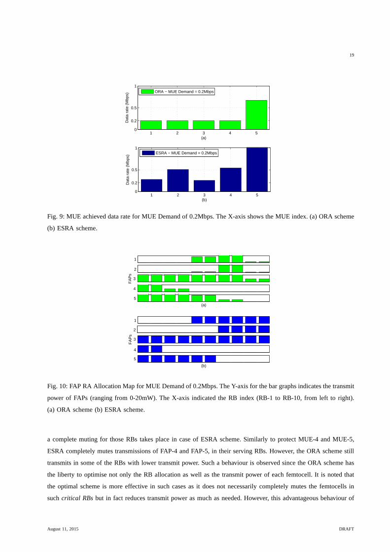
To this end, Fig. 9 (a) and (b) depict the achieved MUE data rates, for a MUE demand of 0.2Mbps: for ORA
August 11, 2015 DRAFT

18
TABLE II: Performance Comparison of various resource allocation schemes.
Schemes
ORA ESRA Reuse-1 Orth. Reuse
MUEs below demand rate [%]
MUE Demand (Mbps)
0.2 0.0 0.0 10.8 0.00.5 0.0 0.0 22.2 0.00.8 0.0 0.0 29.4 0.01.2 0.0 0.0 47.2 0.0
MUE rate 50th percentile [Mbps]
MUE Demand (Mbps)
0.2 0.48 1.54 1.39 1.570.5 0.52 1.58 1.26 1.490.8 0.89 1.77 1.26 1.491.2 1.40 1.97 1.26 1.48
FUE rate 50th percentile [Mbps]
MUE Demand (Mbps)
0.2 12.74 11.98 12.76 13.890.5 12.82 11.28 13.06 13.810.8 12.61 10.57 13.02 13.811.2 12.46 9.68 13.00 13.79
FUE rate 80th percentile [Mbps]
MUE Demand (Mbps)
0.2 17.45 16.25 17.45 15.910.5 17.27 15.30 17.27 15.800.8 17.27 14.63 17.27 15.801.2 17.17 14.08 17.17 15.73
0 100 200 300 400 500 600 700 800
0
100
200
300
400
500
600
700
800
MacroCell
Distance (meters)
Dis
tanc
e (m
eter
s)
FAP−1 FAP−2
FAP−3
FAP−4
FAP−5
1 2 3 4 5
MUEFUE
Fig. 8: Node locations in static scenario. FAP-3 is the only femtocell node not close to a victim user.
and ESRA scheme, respectively. We observe clearer now that in case of ORA, majority of the MUE’s achieved
rate does not exceed the demand. However, in case of ESRA, MUE’s achieved rate is not as close to the demand.
Moreover, Fig. 10 shows the resource (RB and power) allocation map of the FAPs for MUE demand rate of
0.2Mbps. We can see that ORA scheme mutes FAP-1 and FAP-2 in first four RBs on which the nearby MUEs are
being served, however transmits with lower power in the RBs where MUE-3 is being served. On the other hand
August 11, 2015 DRAFT
19
1 2 3 4 50
0.2
0.5
1
(a)
Dat
a ra
te (
Mbp
s)
1 2 3 4 50
0.2
0.5
1
(b)
Dat
a ra
te (
Mbp
s)
ORA − MUE Demand = 0.2Mbps
ESRA − MUE Demand = 0.2Mbps
Fig. 9: MUE achieved data rate for MUE Demand of 0.2Mbps. The X-axis shows the MUE index. (a) ORA scheme
(b) ESRA scheme.
1
2
FA
Ps
4
(a)
5
(b)
5
4
FA
Ps
2
1
3
3
Fig. 10: FAP RA Allocation Map for MUE Demand of 0.2Mbps. The Y-axis for the bar graphs indicates the transmit
power of FAPs (ranging from 0-20mW). The X-axis indicated the RB index (RB-1 to RB-10, from left to right).
(a) ORA scheme (b) ESRA scheme.
a complete muting for those RBs takes place in case of ESRA scheme. Similarly to protect MUE-4 and MUE-5,
ESRA completely mutes transmissions of FAP-4 and FAP-5, in their serving RBs. However, the ORA scheme still
transmits in some of the RBs with lower transmit power. Such abehaviour is observed since the ORA scheme has
the liberty to optimise not only the RB allocation as well as the transmit power of each femtocell. It is noted that
the optimal scheme is more effective in such cases as it does not necessarily completely mutes the femtocells in
suchcritical RBs but in fact reduces transmit power as much as needed. However, this advantageous behaviour of
August 11, 2015 DRAFT

20
1 2 3 4 50
0.5
1
(a)
Dat
a ra
te (
Mbp
s)
1 2 3 4 50
0.2
0.4
0.6
0.8
1
(b)
Dat
a ra
te (
Mbp
s)
ORA − MUE Demand = 0.5Mbps
ESRA − MUE Demand = 0.5Mbps
Fig. 11: MUE achieved data rate for MUE Demand of 0.5Mbps. TheX-axis shows the MUE index. (a) ORA
scheme (b) ESRA scheme.
1
2
FA
Ps
4
(a)
5
(b)
5
4
FA
Ps
2
1
3
3
Fig. 12: FAP RA Allocation Map for MUE Demand of 0.5Mbps. The Y-axis for the bar graphs indicates the transmit
power of FAPs (ranging from 0-20mW). The X-axis indicated the RB index (RB-1 to RB-10, from left to right).
(a) ORA scheme (b) ESRA scheme.
ORA scheme comes at the cost of extra computational complexity as explained in section IV. We can observe a
similar trend of MUE achieved data rates and resource allocation map in Fig. 11 and 12, where the MUE demand
rate is 0.5Mbps. Furthermore, focusing on FAP-3 which is away from the MUEs, we observe that it is allowed to
transmit on all the RBs with high power, even for the higher MUE demand case.
August 11, 2015 DRAFT

21
VII. C ONCLUSION
In this paper, we tackled the inter-tier interference issuewhich deteriorates the performance of mobile macrocell-
served users in a LTE HetNet environment comprising macrocells and femtocells sharing the same frequency band.
We propose dynamic resource allocation at femtocells to maximise their sum data rate while at the same time
the interference faced by the macrocell-served users is kept below a tolerance threshold, estimated based on their
minimum rate requirement. We analysed the optimal solutionto this problem and also proposed a more practical
scheme which considers femtocell RB muting and significantly reduces computational complexity. Focusing on
the practical application of these dynamic approaches, we furthermore design algorithms to implement them in
a real-world system such as Long-Term Evolution (LTE) networks. Our simulation results compare the dynamic
resource allocation schemes with the conventional Reuse-1and Orthogonal Reuse scheme, and demonstrate that
macro users QoS requirements can be ensured while keeping the femto users data rates at similar high levels.
APPENDIX A
OPTIMAL POWER FOR AGIVEN RB ALLOCATION
For the sake of simplicity of understanding, we suppress thenotations in equation (11) and write L as:
L = φR− λφpΓ− µφp, now replacingφ = 1 andR with equation (3), we getL = log2(1 + p α)− λ p Γ− µ p.
Let, y = log2(1 + p α),
∂L∂p
= ∂y∂p
− λΓ− µ.
Now let, x = (1 + p α) ; y = log2(x),
∵ ∂y∂p
= ∂y∂x
∂x∂p
= 1ln(2)xα = α
ln(2)(1+pα) .
∴ ∂L∂p
= αln(2)(1+pα) − λΓ− µ.
Applying the KKT condition, we equate∂L∂p
= 0;
αln(2)(1+pα) − λΓ− µ = 0. It then follows,
=⇒ αln(2)(1+pα) = µ+ λΓ,
=⇒ α(1+pα) = ln(2)(µ+ λΓ),
=⇒ (1 + pα) = αln(2)(µ+λΓ) ,
=⇒ pα = αln(2)(µ+λΓ) − 1, and we solve forp as:
p = 1ln(2)(µ+λΓ) −
1α
.
APPENDIX B
SUBGRADIENTS OFDUAL FUNCTION
Considering the Lagrangian dual functiong, in equation (9) at two different points(λ,µ) and(
λ′,µ′)
in
the dual variable multidimensional space, whereλ = (λ1, λ2, ...λn, ...λN ), λ′ = (λ1, λ2, ...λ
′n, ...λN ), µ =
(µ1, µ2, ...µm, ...µM ) andµ′ = (µ1, µ2, ...µ′m, ...µM ), we have:
August 11, 2015 DRAFT
22
g(λ,µ) =
maxφ,p L(φ,p,λ,µ),
s.t.
0 ≤ φk,m,n ≤ 1, ∀k ∈ K \ K0,m ∈ M, n;
∑
k∈Km
φk,m,n ≤ 1, ∀m ∈ M, n;
pm,n ≥ 0, ∀m ∈ M, n.
(25)
g(λ′,µ′) =
maxφ,p L(φ,p,λ′,µ′),
s.t.
0 ≤ φk,m,n ≤ 1, ∀k ∈ K \ K0,m ∈ M, n;
∑
k∈Km
φk,m,n ≤ 1, ∀m ∈ M, n;
pm,n ≥ 0, ∀m ∈ M, n.
(26)
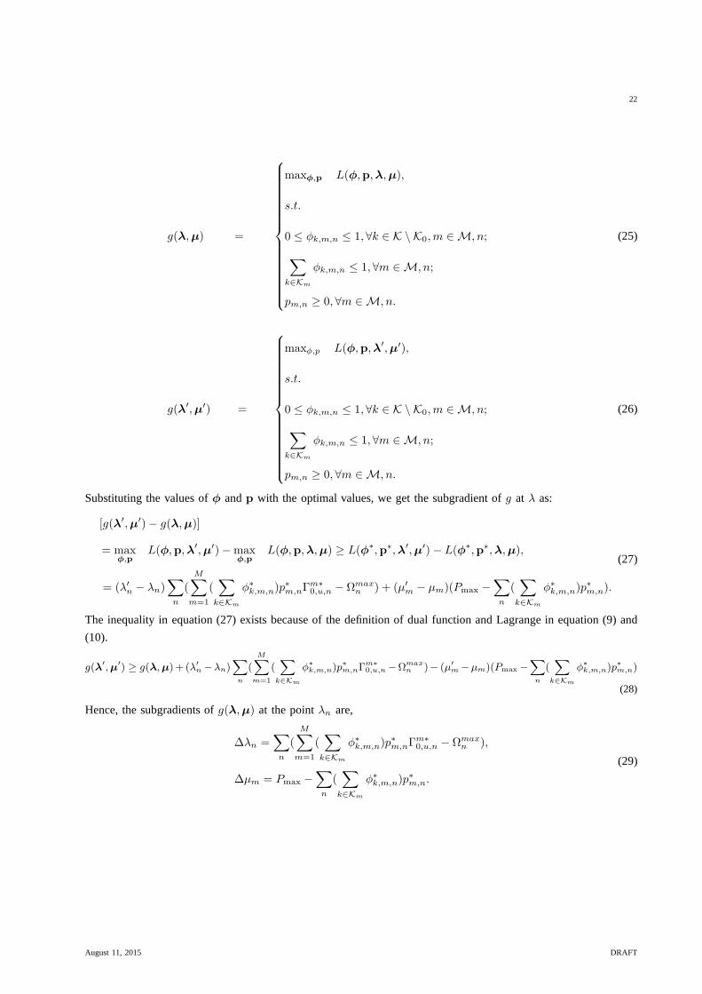
Substituting the values ofφ andp with the optimal values, we get the subgradient ofg at λ as:
[g(λ′,µ′)− g(λ,µ)]
= maxφ,p
L(φ,p,λ′,µ′)−maxφ,p
L(φ,p,λ,µ) ≥ L(φ∗,p∗,λ′,µ′)− L(φ∗,p∗,λ,µ),
= (λ′n − λn)∑
n
(M∑
m=1
(∑
k∈Km
φ∗k,m,n)p∗m,nΓ
m∗0,u,n − Ωmax
n ) + (µ′m − µm)(Pmax −
∑
n
(∑
k∈Km
φ∗k,m,n)p∗m,n).
(27)
The inequality in equation (27) exists because of the definition of dual function and Lagrange in equation (9) and
(10).
g(λ′,µ
′) ≥ g(λ,µ)+ (λ′n −λn)
∑
n
(
M∑
m=1
(∑
k∈Km
φ∗k,m,n)p
∗m,nΓ
m∗0,u,n −Ωmax
n )− (µ′m−µm)(Pmax −
∑
n
(∑
k∈Km
φ∗k,m,n)p
∗m,n)
(28)
Hence, the subgradients ofg(λ,µ) at the pointλn are,
∆λn =∑
n
(M∑
m=1
(∑
k∈Km
φ∗k,m,n)p∗m,nΓ
m∗0,u,n − Ωmax
n ),
∆µm = Pmax −∑
n
(∑
k∈Km
φ∗k,m,n)p∗m,n.
(29)
August 11, 2015 DRAFT

23
REFERENCES
[1] V. Chandrasekhar, J. Andrews, and A. Gatherer, “Femtocell Networks: a Survey,”IEEE Communications Magazine, vol. 46, no. 9, pp.
59–67, 2008.
[2] I. Hwang, B. Song, and S. Soliman, “A Holistic View on Hyper-dense Heterogeneous and Small Cell Networks,”IEEE Communications
Magazine, vol. 51, no. 6, pp. 20–27, June 2013.
[3] S. Navaratnarajah, A. Saeed, M. Dianati, and M. Imran, “Energy Efficiency in Heterogeneous Wireless Access Networks,” IEEE Wireless
Communications Magazine, vol. 20, no. 5, pp. 37–43, October 2013.
[4] A. Saeed, A. Akbari, M. Dianati, and M. A. Imran, “Energy Efficiency Analysis for LTE Macro-Femto HetNets,” inProceedings of 19th
European Wireless Conference (EW), April 2013.
[5] S.-E. Elayoubi and B. Fourestie, “On Frequency Allocation in 3G LTE Systems,” inProceedings of IEEE 17th International Symposium
on Personal, Indoor and Mobile Radio Communications (PIMRC), Sept 2006.
[6] S. Ali and V. C. M. Leung, “Dynamic Frequency Allocation in Fractional Frequency Reused OFDMA Networks,”IEEE Transactions on
Wireless Communications, vol. 8, no. 8, pp. 4286–4295, August 2009.
[7] R. Y. Chang, Z. Tao, J. Zhang, and C.-C. J. Kuo, “A Graph Approach to Dynamic Fractional Frequency Reuse (FFR) in Multi-cell OFDMA
Networks,” in Proceedings of IEEE International Conference on Communications, 2009, pp. 3993–3998.
[8] A. Stolyar and H. Viswanathan, “Self-Organizing Dynamic Fractional Frequency Reuse in OFDMA Systems,” inProceedings of IEEE
27th Conference on Computer Communications (INFOCOM), April 2008.
[9] D. Lopez-Perez, C. Xiaoli, and Z. Jie, “Dynamic DownlinkFrequency and Power Allocation in OFDMA Cellular Networks,” IEEE
Transactions on Communications, vol. 60, no. 10, pp. 2904–2914, 2012.
[10] D. Lopez-Perez, X. Chu, A. V. Vasilakos, and H. Claussen, “Power Minimization Based Resource Allocation for Interference Mitigation
in OFDMA Femtocell Networks,”IEEE Journal on Selected Areas in Communications, vol. 32, no. 2, pp. 333–344, February 2014.
[11] D. Lopez-Perez, X. Chu, A. Vasilakos, and H. Claussen, “On Distributed and Coordinated Resource Allocation for Interference Mitigation
in Self-Organizing LTE Networks,”IEEE/ACM Transactions on Networking, vol. 21, no. 4, pp. 1145–1158, Aug 2013.
[12] J. Ling, D. Chizhik, and R. Valenzuela, “On Resource Allocation in Dense Femto-Deployments,” inProceedings of IEEE International
Conference on Microwaves, Communications, Antennas and Electronics Systems, Nov 2009.
[13] F. Bernardo, R. Agusti, J. Cordero, and C. Crespo, “Self-Optimization of Spectrum Assignment and Transmission Power in OFDMA
Femtocells,” inProceedings of Sixth Advanced International Conference on Telecommunications (AICT), May 2010.
[14] V. Chandrasekhar and J. Andrews, “Spectrum Allocationin Tiered Cellular Networks,”IEEE Transactions on Communications, vol. 57,
no. 10, pp. 3059–3068, October 2009.
[15] J. D. Hobby and H. Claussen, “Deployment Options for Femtocells and Their Impact on Existing Macrocellular Networks,” Bell Labs
Technical Journal, vol. 13, no. 4, pp. 145–160, 2009.
[16] H. Claussen, “Co-Channel Operation of Macro- and Femtocells in a Hierarchical Cell Structure,”International Journal of Wireless
Information Networks, vol. 15, no. 3-4, pp. 137–147, 2008.
[17] M. Arslan, J. Yoon, K. Sundaresan, S. Krishnamurthy, and S. Banerjee, “A Resource Management System for Interference Mitigation in
Enterprise OFDMA Femtocells,”IEEE/ACM Transactions on Networking, vol. 21, no. 5, pp. 1447–1460, Oct 2013.
[18] X. Chu, Y. Wu, D. Lopez-Perez, and X. Tao, “On Providing Downlink Services in Collocated Spectrum-Sharing Macro andFemto
Networks,” IEEE Transactions on Wireless Communications, vol. 10, no. 12, pp. 4306–4315, December 2011.
[19] M. S. Alam, J. W. Mark, and X. S. Shen, “Relay Selection and Resource Allocation for Multi-User Cooperative OFDMA Networks,”
IEEE Transactions on Wireless Communications, vol. 12, no. 5, pp. 2193–2205, May 2013.
[20] W. Yu and R. Lui, “Dual Methods for Nonconvex Spectrum Optimization of Multicarrier Systems,”IEEE Transactions on Communications,
vol. 54, no. 7, pp. 1310–1322, July 2006.
[21] W. Yi, Z. Dongmei, J. Hai, and W. Ye, “A Novel Spectrum Arrangement Scheme for Femto Cell Deployment in LTE Macro Cells,” in
Personal, Indoor and Mobile Radio Communications, 2009 IEEE 20th International Symposium on, 2009.
August 11, 2015 DRAFT