Dynamic Channel Assignment for Multihop Cellular Networks with Any Reuse Factor
3
346 IEEE COMMUNICATIONS LETTERS, VOL. 12, NO. 5, MAY 2008 Dynamic Channel Assignment for Multihop Cellular Networks with Any Reuse Factor Xue Jun Li, Peter Han Joo Chong, Member, IEEE, and Jie Zhan Abstract—A clustered multihop cellular network (cMCN) architecture is recently proposed and studied using fixed channel assignment (FCA) with a reuse factor, Nr =7. In this Letter, we propose and develop a multihop dynamic channel assignment (mDCA) scheme applicable with any reuse factor. The mDCA assigns channels with the knowledge of the information about interference in surrounding cells. Simulations show that the capacity improvements at call blocking probability of 1% for mDCA over the conventional FCA are 96% and 210% for Nr =4 and Nr =7, respectively. Index Terms— Multihop cellular networks, channel assign- ment, mobile ad hoc networks, clustering. I. I NTRODUCTION F ROM a recent estimation, cellular subscribers are ex- pected to rise to 3.96 billion by the year 2011. To meet the increasing demand on wireless access, Hsu and Lin pro- posed multihop cellular network (MCN) [1] to incorporate the flexibility of ad hoc networking [2] into traditional single-hop cellular networks (SCNs). MCN adopts multihop transmission through peer-to-peer communication among mobile stations (MSs). Therefore, channel assignment for this promising net- work architecture becomes even more difficult. Recently, a number of MCN architectures [1, 3-7] have been proposed and studied. For iCAR [3], fixed ad hoc relay stations (ARSs) are deployed to enable traffic balancing. iCAR is based on the idea of diverting the traffic from congested cells to non-congested cells using unlicensed frequency band other than the cellular frequency band, such as the industrial, scientific and medical (ISM) band. The communication link between MSs and relay stations (RSs) uses the ISM band. In [4], Yanmaz and Tonguz found that the efficiency of iCAR is dependent on the number of available ISM relay channels (CHs). Next, UCAN [5] is to increase the user data rate and system throughput through multihop relaying using the ISM band as well. In these papers, there is no detailed description on how to select and allocate the relay CHs to a MS/RS for each hop. In [6], an ad hoc GSM (A-GSM) protocol was proposed to use the cellular frequency band for RSs to cover dead spots and increase the system capacity. However, it did not clearly address how the resources are allocated to MSs and RSs. Similarly, MCN proposed in [1] also uses the cellular frequency band to implement multihop transmission, but no detailed description of channel assignment is provided. In our recent work [7], clustered MCN (cMCN) is proposed and studied using fixed channel assignment (FCA). It uses cellular frequency band for traffic relaying. Results [7] show Manuscript received January 13, 2008. The associate editor coordinating the review of this letter and approving it for publication was L. Dasilva. The authors are with the Department of Electrical and Electronic En- gineering, Nanyang Technological University, Singapore 639798 (e-mail: [email protected], [email protected]). Digital Object Identifier 10.1109/LCOMM.2008.080054. that cMCN with FCA can improve the system capacity. However, FCA is not able to cope with varying traffic patterns and thus may result in certain deficiencies. As we know, dynamic channel assignment (DCA) is more desirable to deal with varying traffic patterns and provide higher flexibility. In addition, the proposed asymmetric FCA (AFCA) for cMCN in [7] is limited to a reuse factor of 7. Other reuse factors are not applicable. Therefore, in this Letter, we investigate the feasibility of applying DCA in cMCN and propose a multihop DCA (mDCA) scheme applicable with any reuse factor. II. CLUSTERED MULTIHOP CELLULAR NETWORK The objective of cMCN is to achieve the characteristics of the macrocell/microcell hierarchically overlaid system by applying MANET clustering [7]. In SCNs, the BS will cover the whole macrocell with a radius of r M , while cMCN divides the macrocell area into seven microcells with a radius of r m as shown in Fig. 1. Six virtual microcells will be formed around the central microcell. We use a dedicated information port (DIP), located at the center of each virtual microcell, as a clusterhead. The function of a DIP is to allocate CHs to the MSs within its virtual microcell, to select a MS as a RS, to determine the routing path and to help its BS on the functions of authentication, authorization, and accounting (AAA). Different from the ARSs in iCAR [3], DIPs are not involved in data relaying. Therefore, their complexity is much lower than a BS, so does the cost. Each virtual microcell can be divided into two regions: inner half and outer half. The inner half is near the central microcell. III. PROPOSED MDCA SCHEME First, we look at the channel assignment procedure under mDCA, which is shown in Fig. 1 and described as follows. 1) One-hop Calls: A call originated from a MS in the central microcell, e.g., MS 1 in microcell A, is considered as a one- hop call. It requires one UL CH and one DL CH from the microcell A. The call is accepted if microcell A finds one free UL CH and one free DL CH. Otherwise, the call is blocked. 2) Two-hop Call: A call originated from a MS in the inner half region of a virtual microcell, e.g., MS 2 in region B 1 of microcell B, is considered as a two-hop call. The BS will find another MS in microcell A as a RS, e.g., RS 0 in Fig. 1. For UL transmission, a two-hop call requires one UL CH from the microcell B and one UL CH from microcell A. The CHs are used for the transmission from MS 2 to RS 0 and from RS 0 to the BS, respectively. For DL transmission, a two-hop call requires two DL CHs from microcell A; one CH is for the transmission from the BS to RS 0 and the other is for that from RS 0 to MS 2 . The call is accepted if all the following conditions satisfy: (i) microcell B finds one free UL CH; (ii) 1089-7798/08$25.00 c 2008 IEEE
Transcript of Dynamic Channel Assignment for Multihop Cellular Networks with Any Reuse Factor
346 IEEE COMMUNICATIONS LETTERS, VOL. 12, NO. 5, MAY 2008
Dynamic Channel Assignment for Multihop Cellular Networks withAny Reuse Factor
Xue Jun Li, Peter Han Joo Chong, Member, IEEE, and Jie Zhan
Abstract— A clustered multihop cellular network (cMCN)architecture is recently proposed and studied using fixed channelassignment (FCA) with a reuse factor, Nr=7. In this Letter, wepropose and develop a multihop dynamic channel assignment(mDCA) scheme applicable with any reuse factor. The mDCAassigns channels with the knowledge of the information aboutinterference in surrounding cells. Simulations show that thecapacity improvements at call blocking probability of 1% formDCA over the conventional FCA are 96% and 210% for Nr=4and Nr=7, respectively.
Index Terms— Multihop cellular networks, channel assign-ment, mobile ad hoc networks, clustering.
I. INTRODUCTION
FROM a recent estimation, cellular subscribers are ex-pected to rise to 3.96 billion by the year 2011. To meet
the increasing demand on wireless access, Hsu and Lin pro-posed multihop cellular network (MCN) [1] to incorporate theflexibility of ad hoc networking [2] into traditional single-hopcellular networks (SCNs). MCN adopts multihop transmissionthrough peer-to-peer communication among mobile stations(MSs). Therefore, channel assignment for this promising net-work architecture becomes even more difficult.
Recently, a number of MCN architectures [1, 3-7] havebeen proposed and studied. For iCAR [3], fixed ad hoc relaystations (ARSs) are deployed to enable traffic balancing. iCARis based on the idea of diverting the traffic from congestedcells to non-congested cells using unlicensed frequency bandother than the cellular frequency band, such as the industrial,scientific and medical (ISM) band. The communication linkbetween MSs and relay stations (RSs) uses the ISM band. In[4], Yanmaz and Tonguz found that the efficiency of iCARis dependent on the number of available ISM relay channels(CHs). Next, UCAN [5] is to increase the user data rate andsystem throughput through multihop relaying using the ISMband as well. In these papers, there is no detailed descriptionon how to select and allocate the relay CHs to a MS/RS foreach hop. In [6], an ad hoc GSM (A-GSM) protocol wasproposed to use the cellular frequency band for RSs to coverdead spots and increase the system capacity. However, it didnot clearly address how the resources are allocated to MSs andRSs. Similarly, MCN proposed in [1] also uses the cellularfrequency band to implement multihop transmission, but nodetailed description of channel assignment is provided.
In our recent work [7], clustered MCN (cMCN) is proposedand studied using fixed channel assignment (FCA). It usescellular frequency band for traffic relaying. Results [7] show
Manuscript received January 13, 2008. The associate editor coordinatingthe review of this letter and approving it for publication was L. Dasilva.
The authors are with the Department of Electrical and Electronic En-gineering, Nanyang Technological University, Singapore 639798 (e-mail:[email protected], [email protected]).
Digital Object Identifier 10.1109/LCOMM.2008.080054.
that cMCN with FCA can improve the system capacity.However, FCA is not able to cope with varying traffic patternsand thus may result in certain deficiencies. As we know,dynamic channel assignment (DCA) is more desirable to dealwith varying traffic patterns and provide higher flexibility. Inaddition, the proposed asymmetric FCA (AFCA) for cMCNin [7] is limited to a reuse factor of 7. Other reuse factorsare not applicable. Therefore, in this Letter, we investigate thefeasibility of applying DCA in cMCN and propose a multihopDCA (mDCA) scheme applicable with any reuse factor.
II. CLUSTERED MULTIHOP CELLULAR NETWORK
The objective of cMCN is to achieve the characteristicsof the macrocell/microcell hierarchically overlaid system byapplying MANET clustering [7]. In SCNs, the BS will coverthe whole macrocell with a radius of rM , while cMCN dividesthe macrocell area into seven microcells with a radius of rm
as shown in Fig. 1. Six virtual microcells will be formedaround the central microcell. We use a dedicated informationport (DIP), located at the center of each virtual microcell,as a clusterhead. The function of a DIP is to allocate CHsto the MSs within its virtual microcell, to select a MS asa RS, to determine the routing path and to help its BS onthe functions of authentication, authorization, and accounting(AAA). Different from the ARSs in iCAR [3], DIPs are notinvolved in data relaying. Therefore, their complexity is muchlower than a BS, so does the cost. Each virtual microcell canbe divided into two regions: inner half and outer half. Theinner half is near the central microcell.
III. PROPOSED MDCA SCHEME
First, we look at the channel assignment procedure undermDCA, which is shown in Fig. 1 and described as follows.
1) One-hop Calls: A call originated from a MS in the centralmicrocell, e.g., MS1 in microcell A, is considered as a one-hop call. It requires one UL CH and one DL CH from themicrocell A. The call is accepted if microcell A finds one freeUL CH and one free DL CH. Otherwise, the call is blocked.
2) Two-hop Call: A call originated from a MS in the innerhalf region of a virtual microcell, e.g., MS2 in region B1 ofmicrocell B, is considered as a two-hop call. The BS will findanother MS in microcell A as a RS, e.g., RS0 in Fig. 1. ForUL transmission, a two-hop call requires one UL CH fromthe microcell B and one UL CH from microcell A. The CHsare used for the transmission from MS2 to RS0 and fromRS0 to the BS, respectively. For DL transmission, a two-hopcall requires two DL CHs from microcell A; one CH is forthe transmission from the BS to RS0 and the other is for thatfrom RS0 to MS2. The call is accepted if all the followingconditions satisfy: (i) microcell B finds one free UL CH; (ii)
1089-7798/08$25.00 c© 2008 IEEE

LI et al.: DYNAMIC CHANNEL ASSIGNMENT FOR MULTIHOP CELLULAR NETWORKS WITH ANY REUSE FACTOR 347
MS1
MS2
MS3
RS0
RS1
RS2
BS
outer half region
uplinkdownlink
central microcell
inner half region
virtual microcell
rM
A
B
rm
B1
B2
original macrocell
area
Fig. 1. Channel assignment in cMCN with mDCA.
6
89
1011
13
14
1617
1819
20
2122
23
2526
27
2829
3031
32
34
35
3738
3940
41
4243
44
464748
BS
central microcellvirtual
microcell0 12
34
5
7
12
15
24
33
36
45
virtualmacrocell
Fig. 2. The simulated 49-cell network.
microcell A finds one free UL CH; and (iii) microcell A findstwo free DL CHs. Otherwise, the call is blocked.
3) Three-hop Calls: A call originated from a MS in the outerhalf region of a virtual microcell, e.g., MS3 in region B2 ofmicrocell B, is considered as a three-hop call. The BS findsanother two MSs as the RSs; one, RS2, is in the region B1 andthe other, RS1, is in microcell A. For UL transmission, a three-hop call requires two UL CHs from microcell B and one ULCH from microcell A. The CHs are used for the transmissionfrom MS2 to RS2, from RS2 to RS1 and RS1 to the BS,respectively. For DL transmission, a three-hop call requirestwo DL CHs from microcell A and one DL CH from microcellB, which are for the transmission from the BS to RS1, fromRS1 to RS2 and from RS2 to MS3, respectively. A three-hop call is accepted if all the following conditions satisfy: (i)microcell A finds one free UL CH; (ii) microcell B finds twofree UL CHs; (iii) microcell A finds two free DL CHs; and (iv)microcell B finds one free DL CH. Otherwise, it is blocked.
Next, the channel assignment is based on the informationprovided in the Interference Information Tables (IITs). Twoglobal IITs, which store, update and process the channel status,are located in the mobile switching center (MSC) for uplink(UL) and downlink (DL). We assume that every DIP is ableto access to the global IITs through its corresponding BSusing a separate control CH. As shown in Fig. 2, a 49-microcell network model with 7 macrocells is considered.The UL IIT contains information of the entire N UL CHs,as shown in Table I. The IIT for DL is similar and not shownhere. Another table, the Interference Constraint Table (ICT),as shown in Table II, contains the information of interfering
TABLE I
INTERFERENCE INFORMATION TABLE
ChannelCell 1 2 3 ... N
0 L L 2L ... L1 2L U22 ... U33
2 L L 2L ... 2L... ... ... ... ... ...48 U22 L U33 ...
TABLE II
INTERFERENCE CONSTRAINT TABLE
Interfering Cells with Different Nr
Nr=7Cell Central Nr=4 � �
Microcell Nr=3 � � � �
1 2 3 ... 6 ... 12 ... 180 3 40 46 2 ... 41 ... 39 ... 341 3 41 0 3 ... 35 ... 40 ... 28... ... ... ... ... ... ... ... ... ... ...24 24 17 18 23 ... 31 ... 19 ... 26... ... ... ... ... ... ... ... ... ... ...48 45 45 47 7 ... 46 ... 44 ... 40
cells (including the central microcell) for each microcell. ICTis also located in the MSC. Different reuse factor, Nr, canbe used in ICT as shown in Table II. For example, for Nr=3,the number of interfering cells is six and they are located inthe first surrounding tier. Refer to Fig. 2 and Table II, theinterfering cells for cell 24 are cells 17, 18, 23, 25, 30, 31.There is no special sequence for the interfering cells in TableII, which is purely based on the cell configuration in Fig. 2.By using the appropriate set of interfering cell information inICT, we can apply mDCA with any reuse factor Nr.
The content of an IIT is described as follows. For clarity,we denote the set of interfering cells of any microcell A asI(A), which varies with Nr. The information of I(A) can beobtained from the ICT.
1) Used Channels: A letter ’U11/22/33’ in the (microcell A,CH j) box indicates that CH j is a used CH in microcell A;’U11’ indicates the first-hop CH; ’U22’ indicates the second-hop CH and ’U33’ indicates the third-hop CH. The first-hopCH means the CH used between the BS and a MS in thecentral microcell. The second-hop CH means the CH usedbetween the MS in the central microcell and the MS in theinner half region of a virtual microcell. The third-hop CHmeans the CH used between the MS in the inner half regionof a virtual microcell and the MS in the outer half region ofa virtual microcell.
2) Locked Channel: A letter ’L’ in (microcell A, CH j) boxindicates that one cell in the set I(A), say microcell X, is usingCH j. We refer microcell X as a locking cell and microcell Aas a locked cell for CH j.
3) Free Channels: An empty (microcell A, CH j) boxindicates that CH j is a free CH for microcell A.
Then, the channel searching strategy is described as follows.When a new call arrives, mDCA always searches for a CHfrom a lower-numbered CH to a higher-numbered CH in itscentral microcell from the UL IIT. Once a free CH is found, itis assigned to the first-hop link. Similarly, mDCA attempts tofind the UL CHs for second- or third-hop links for that call inits virtual microcell from the UL IIT if it is a multihop call. For
348 IEEE COMMUNICATIONS LETTERS, VOL. 12, NO. 5, MAY 2008
30 35 40 45 50 55 60 65 7010
−4
10−3
10−2
10−1
100
Offered Traffic (Erlangs/Macrocell)
Cal
l Blo
ckin
g Pr
obab
ility
Pb,U
, Nr=4
Pb,D
, Nr=4
Pb,U
, Nr=7
Pb,D
, Nr=7
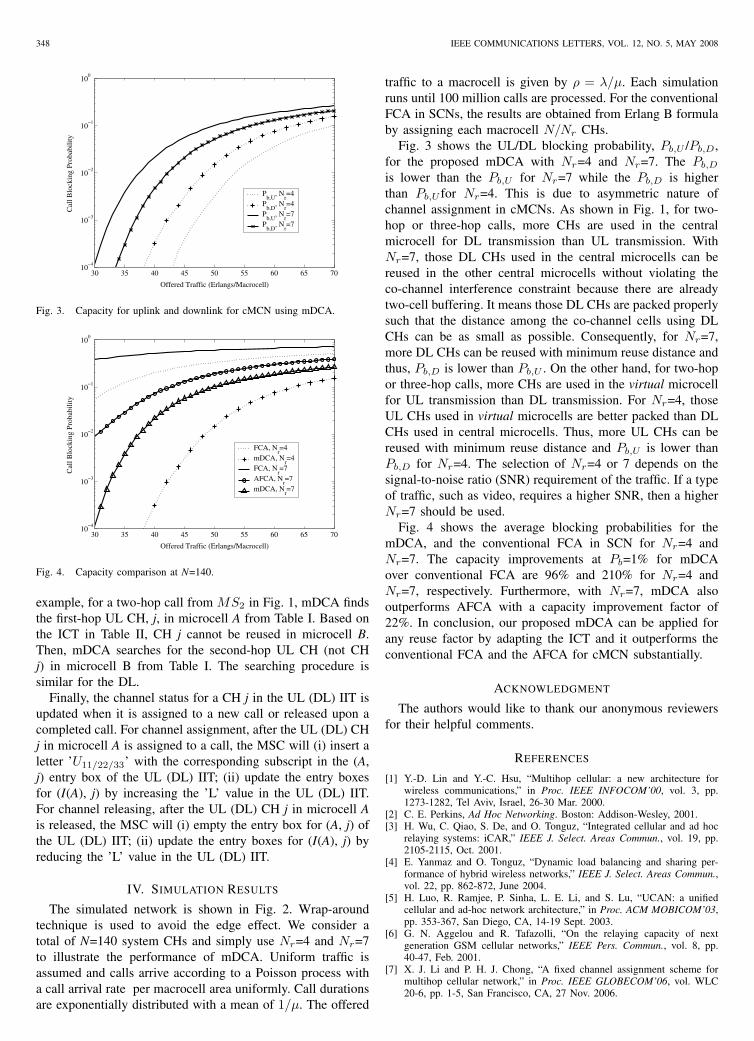
Fig. 3. Capacity for uplink and downlink for cMCN using mDCA.
30 35 40 45 50 55 60 65 7010
−4
10−3
10−2
10−1
100
Offered Traffic (Erlangs/Macrocell)
Cal
l Blo
ckin
g Pr
obab
ility
FCA, Nr=4
mDCA, Nr=4
FCA, Nr=7
AFCA, Nr=7
mDCA, Nr=7
Fig. 4. Capacity comparison at N=140.
example, for a two-hop call from MS2 in Fig. 1, mDCA findsthe first-hop UL CH, j, in microcell A from Table I. Based onthe ICT in Table II, CH j cannot be reused in microcell B.Then, mDCA searches for the second-hop UL CH (not CHj) in microcell B from Table I. The searching procedure issimilar for the DL.
Finally, the channel status for a CH j in the UL (DL) IIT isupdated when it is assigned to a new call or released upon acompleted call. For channel assignment, after the UL (DL) CHj in microcell A is assigned to a call, the MSC will (i) insert aletter ’U11/22/33’ with the corresponding subscript in the (A,j) entry box of the UL (DL) IIT; (ii) update the entry boxesfor (I(A), j) by increasing the ’L’ value in the UL (DL) IIT.For channel releasing, after the UL (DL) CH j in microcell Ais released, the MSC will (i) empty the entry box for (A, j) ofthe UL (DL) IIT; (ii) update the entry boxes for (I(A), j) byreducing the ’L’ value in the UL (DL) IIT.
IV. SIMULATION RESULTS
The simulated network is shown in Fig. 2. Wrap-aroundtechnique is used to avoid the edge effect. We consider atotal of N=140 system CHs and simply use Nr=4 and Nr=7to illustrate the performance of mDCA. Uniform traffic isassumed and calls arrive according to a Poisson process witha call arrival rate per macrocell area uniformly. Call durationsare exponentially distributed with a mean of 1/µ. The offered
traffic to a macrocell is given by ρ = λ/µ. Each simulationruns until 100 million calls are processed. For the conventionalFCA in SCNs, the results are obtained from Erlang B formulaby assigning each macrocell N/Nr CHs.
Fig. 3 shows the UL/DL blocking probability, Pb,U /Pb,D,for the proposed mDCA with Nr=4 and Nr=7. The Pb,D
is lower than the Pb,U for Nr=7 while the Pb,D is higherthan Pb,U for Nr=4. This is due to asymmetric nature ofchannel assignment in cMCNs. As shown in Fig. 1, for two-hop or three-hop calls, more CHs are used in the centralmicrocell for DL transmission than UL transmission. WithNr=7, those DL CHs used in the central microcells can bereused in the other central microcells without violating theco-channel interference constraint because there are alreadytwo-cell buffering. It means those DL CHs are packed properlysuch that the distance among the co-channel cells using DLCHs can be as small as possible. Consequently, for Nr=7,more DL CHs can be reused with minimum reuse distance andthus, Pb,D is lower than Pb,U . On the other hand, for two-hopor three-hop calls, more CHs are used in the virtual microcellfor UL transmission than DL transmission. For Nr=4, thoseUL CHs used in virtual microcells are better packed than DLCHs used in central microcells. Thus, more UL CHs can bereused with minimum reuse distance and Pb,U is lower thanPb,D for Nr=4. The selection of Nr=4 or 7 depends on thesignal-to-noise ratio (SNR) requirement of the traffic. If a typeof traffic, such as video, requires a higher SNR, then a higherNr=7 should be used.
Fig. 4 shows the average blocking probabilities for themDCA, and the conventional FCA in SCN for Nr=4 andNr=7. The capacity improvements at Pb=1% for mDCAover conventional FCA are 96% and 210% for Nr=4 andNr=7, respectively. Furthermore, with Nr=7, mDCA alsooutperforms AFCA with a capacity improvement factor of22%. In conclusion, our proposed mDCA can be applied forany reuse factor by adapting the ICT and it outperforms theconventional FCA and the AFCA for cMCN substantially.
ACKNOWLEDGMENT
The authors would like to thank our anonymous reviewersfor their helpful comments.
REFERENCES
[1] Y.-D. Lin and Y.-C. Hsu, “Multihop cellular: a new architecture forwireless communications,” in Proc. IEEE INFOCOM’00, vol. 3, pp.1273-1282, Tel Aviv, Israel, 26-30 Mar. 2000.
[2] C. E. Perkins, Ad Hoc Networking. Boston: Addison-Wesley, 2001.[3] H. Wu, C. Qiao, S. De, and O. Tonguz, “Integrated cellular and ad hoc
relaying systems: iCAR,” IEEE J. Select. Areas Commun., vol. 19, pp.2105-2115, Oct. 2001.
[4] E. Yanmaz and O. Tonguz, “Dynamic load balancing and sharing per-formance of hybrid wireless networks,” IEEE J. Select. Areas Commun.,vol. 22, pp. 862-872, June 2004.
[5] H. Luo, R. Ramjee, P. Sinha, L. E. Li, and S. Lu, “UCAN: a unifiedcellular and ad-hoc network architecture,” in Proc. ACM MOBICOM’03,pp. 353-367, San Diego, CA, 14-19 Sept. 2003.
[6] G. N. Aggelou and R. Tafazolli, “On the relaying capacity of nextgeneration GSM cellular networks,” IEEE Pers. Commun., vol. 8, pp.40-47, Feb. 2001.
[7] X. J. Li and P. H. J. Chong, “A fixed channel assignment scheme formultihop cellular network,” in Proc. IEEE GLOBECOM’06, vol. WLC20-6, pp. 1-5, San Francisco, CA, 27 Nov. 2006.


![Home | University of Waterloo | University of Waterloo - IEEE ......in multihop cellular network (MCNs) [13], delay tolerant networks (DTNs) [14]. textcolorblueMahmoud and Shen [15]](https://static.fdocuments.in/doc/165x107/60a0322eb6f8cb51be352138/home-university-of-waterloo-university-of-waterloo-ieee-in-multihop.jpg)