Dynamic Calibrationof Current-Steering DACclass.ece.iastate.edu/vlsi2/docs/Papers...
4
Dynamic Calibration of Current-Steering DAC Chao Su and R.L Geiger Department of Electrical and Computer Engineering Iowa State University Ames, IA, 50010, USA schao,rgeiger(iastate.edu Abstract-High accuracy Digital to Analog Converters (DACs) exist for improving the output impedance of the current are becoming increasingly important as the common used source. For example, cascoded current sources and current- building block in communication systems. With the increasing of steering switches can be used to increase the output the update rate, dynamic performance of such DACs at high impedance. frequencies is ofparticular interest. The dynamic performance is often characterized by the spurious free dynamic range (SFDR) Many calibration approaches [2], [5], [6] have been and the SFDR is limited by the spectral harmonics which are reported in the literatures for improving DAC performance attributed by system nonlinearities. In this paper, the dynamic focusing mainly on reducing the static nonlinearity. In higher nonlinearity is analyzed and its effect on the output waveform is frequency ranges, little has been presented to lower the discussed. A novel approach is presented to calibrate the dynamic dynamic nonlinearities [7]. Some modest improvements in errors. The validity of this approach is demonstrated with a 15-bit high frequency SFDR have been reported with return-to-zero current steering DAC. Simulation results show that the approach structures (RTZ) at the expense of sacrificing half of the is robust and the SFDR can be correspondingly significantly signal power. improved by using this calibration scheme. For video and wireless telecommunication applications, both static linearity and dynamic linearity are important I. INTRODUCTION because the static and dynamic nonlinearities contribute to In signal processing and telecommunication systems, the undesired harmonics in the DAC output. In this paper, a high accuracy Digital to Analog Converters (DAC) are novel dynamic DAC nonlinearity calibration approach is becoming more and more important. The DAC is used to proposed that can improve high frequency SFDR without reconstruct an analog signal from an arbitrary digital attenuation of the output signal power by compensating waveform. This key part often limits the accuracy and speed dynamic errors at the output with extra pulses. Simulation of the overall system. Several different architectures are used results from a prototype 15-bit current-steering DAC are to build the DACs. Amongst them, the resistor-loaded used to validate this approach. current-steering DAC is exclusively used when high speed and high accuracy are required. In communication II. DYNAMIC NONLINEARITIES ANALYSIS AND applications, DAC quality is often determined by the high CALIBRATION APPROACH frequency spectral purity of the output signal and this is In a DAC, nonlinearities exist during transient. The dominantly determined by the nonlinearities of the DAC. influence of the nonlinearities on the distortion performance The spurious free dynamic range (SFDR) is a widely used of the DAC can be described in both time and frequency measure for the linearity of the converter [1]. domain. In time domain, the static nonlinearities are SFDR degrades with both static and dynamic dominantly attributable to nonlinear settling artifacts in the nonlinearities. The main static errors arise from the current output such as insufficient settling time while the dynamic sources mismatch and their finite output impedances. These nonlinearities are caused by timing skew, slewing and error sources cause inaccurate settling of DAC outputs. The glitches, etc. current source mismatch is mainly due to the random Dynamic properties are given by the transition between variations that can be attributed to local random variations two states. Most of these occur at the start of the transition and gradient effects [2]. Special layout and placement techniques, such as common centroide technique, judicious switch sequencing, and Q2 random walks [3]-[5] can be used frequency increases, the dynamic nonlinearity components 1 1 ner *r 1 ~~~~~~~becomelarger so the linearit degrades and the ma nitude to reduce these effects. Even if the current sources are bg, s g g perfectly matched, the output current of the current sources of SFDR decreases. In order to improve the SFDR of the may still vary.withheoutputvoltagebcaus finiteness DACs, the effects of the dynamic nonlinearities must be m v the output voltae encase rth e reduced. Cong in her paper [2] improved low and high frequency SFDR with very low power and small area. The 0-7803-9390-2/06/$20.00 ©)2006 IEEE 117 ISCAS 2006
Transcript of Dynamic Calibrationof Current-Steering DACclass.ece.iastate.edu/vlsi2/docs/Papers...

Dynamic Calibration of Current-Steering DACChao Su and R.L Geiger
Department of Electrical and Computer EngineeringIowa State UniversityAmes, IA, 50010, USA
schao,rgeiger(iastate.edu
Abstract-High accuracy Digital to Analog Converters (DACs) exist for improving the output impedance of the currentare becoming increasingly important as the common used source. For example, cascoded current sources and current-building block in communication systems. With the increasing of steering switches can be used to increase the outputthe update rate, dynamic performance of such DACs at high impedance.frequencies is ofparticular interest. The dynamic performance isoften characterized by the spurious free dynamic range (SFDR) Many calibration approaches [2], [5], [6] have beenand the SFDR is limited by the spectral harmonics which are reported in the literatures for improving DAC performanceattributed by system nonlinearities. In this paper, the dynamic focusing mainly on reducing the static nonlinearity. In highernonlinearity is analyzed and its effect on the output waveform is frequency ranges, little has been presented to lower thediscussed. A novel approach is presented to calibrate the dynamic dynamic nonlinearities [7]. Some modest improvements inerrors. The validity ofthis approach is demonstrated with a 15-bit high frequency SFDR have been reported with return-to-zerocurrent steering DAC. Simulation results show that the approach structures (RTZ) at the expense of sacrificing half of theis robust and the SFDR can be correspondingly significantly signal power.improved by using this calibration scheme.
For video and wireless telecommunication applications,both static linearity and dynamic linearity are important
I. INTRODUCTION because the static and dynamic nonlinearities contribute toIn signal processing and telecommunication systems, the undesired harmonics in the DAC output. In this paper, a
high accuracy Digital to Analog Converters (DAC) are novel dynamic DAC nonlinearity calibration approach isbecoming more and more important. The DAC is used to proposed that can improve high frequency SFDR withoutreconstruct an analog signal from an arbitrary digital attenuation of the output signal power by compensatingwaveform. This key part often limits the accuracy and speed dynamic errors at the output with extra pulses. Simulationof the overall system. Several different architectures are used results from a prototype 15-bit current-steering DAC areto build the DACs. Amongst them, the resistor-loaded used to validate this approach.current-steering DAC is exclusively used when high speedand high accuracy are required. In communication II. DYNAMIC NONLINEARITIES ANALYSIS ANDapplications, DAC quality is often determined by the high CALIBRATION APPROACHfrequency spectral purity of the output signal and this is In a DAC, nonlinearities exist during transient. Thedominantly determined by the nonlinearities of the DAC. influence of the nonlinearities on the distortion performanceThe spurious free dynamic range (SFDR) is a widely used of the DAC can be described in both time and frequencymeasure for the linearity of the converter [1]. domain. In time domain, the static nonlinearities are
SFDR degrades with both static and dynamic dominantly attributable to nonlinear settling artifacts in thenonlinearities. The main static errors arise from the current output such as insufficient settling time while the dynamicsources mismatch and their finite output impedances. These nonlinearities are caused by timing skew, slewing anderror sources cause inaccurate settling of DAC outputs. The glitches, etc.current source mismatch is mainly due to the random Dynamic properties are given by the transition betweenvariations that can be attributed to local random variations two states. Most of these occur at the start of the transitionand gradient effects [2]. Special layout and placementtechniques, such as common centroide technique, judiciousswitch sequencing, and Q2 random walks [3]-[5] can be used frequency increases, the dynamic nonlinearity components
1 1 ner *r 1 ~~~~~~~becomelarger so the linearit degrades and the ma nitudeto reduce these effects. Even if the current sources are bg, s g gperfectly matched, the output current of the current sources of SFDR decreases. In order to improve the SFDR of themaystillvary.withheoutputvoltagebcaus finiteness DACs, the effects of the dynamic nonlinearities must be
m v the output voltae encase rthe reduced. Cong in her paper [2] improved low and highfrequency SFDR with very low power and small area. The
0-7803-9390-2/06/$20.00 ©)2006 IEEE 117 ISCAS 2006
approach is good at low frequency but the SFDR still ni +n2 Sdegrades quickly with increasing frequency. Bugeja's * astructure [7] improved dynamic linearity at high frequencyby using "attenuate and track" approach. But this Dynamic.Calibration.DA.improvement is at the price of a factor of 2 in the signalpower. The main reason of the improvement of dynamic Sti Elinearity in Bugeja's approach is primarily due to thesuppression of the prior code dependence. So measures can I
be adopted to improve the dynamic linearity without lose ofsignal power.
The dynamic distortion is caused by the nonlinear Fig. 1 DAC calibration schemebehavior of the DAC. The nonlinear behavior can bemodeled as a function of the input sequence. The errors E at Ideal Idealthe output of the DAC can be expressed as
E=-:f (Ao, Al, ...An-,, An, .. (1) ...........where AO, Al, ..., An-,, Ann, ... is the input sequence. For Actn
most DACs, the output error is primarily attributed by the Cal.present input code and the previous input code, i.e. for an D _input code of A1,, the error will be given by E=f (Anl1, An). ii AtThe error can be divided into two categories: one occurs Atduring the transition region between two consecutivechanging states which can be called dynamic glitch error Fig.2 MSB glitch calibration conceptual illustrationcaused by the nonlinearities during this region, the other is DAC is segmented into a most significant bit (MSB) partthe dynamic settling error attributed to the variation of theDAC output settled value compared to the desired one. Both (nbi)adalstigfcntitLS)pr(n-t.Ththermometer decoding is used in the MSB part to reduce theof them are present input code, Xn, and the difference, Xd,ff, output glitches. The LSB part is implemented with a binarydependent. Here Xdiff is the difference between the present structure.code and previous code, Xn-1, Xdifff Xn- Xn-1. The actualDAC output can be regarded as: For the dynamic settling error calibration, the
'out -Id (2) compensation pulse width At,t is the same as the clock periodout-ideal- d ( ) T, and the pulse height is the mean variation between the
Where lout is the DAC actual output, 'ideal is the ideal output settled value and the desired output value but oppositeoutput, -Id is the error caused by nonlinearities. -Id includes sign. The dynamic glitch error width is very narrowthe dynamic glitcherror anddynamic settlingeerror. compared to the clock period. The error can be simply
modeled as glitches with certain width and height for everyThe basic idea of our approach is to generate an amount states transition and can be compensated by narrow pulses.
of current with the same magnitude but opposite sign to -Id Fig.2 shows a conceptual illustration of the dynamic glitchfrom a dynamic calibration DAC, then an ideal output can be calibration. If a waveform that is a vertical flip of the glitchesobtained by adding the current to the original DAC to can be generated and added to the output waveform at eachcompensate the nonlinearity error. transition period, the glitches can be canceled perfectly. But
Fig. 1 shows the architecture of a DAC with its dynamic it is hard to generate such an analog waveform, so digitalcalibration. It consists of a static error calibrated DAC as pulses are used to compensate the glitches. For simplicity,used by Cong in [2], a Dynamic Calibration DAC and a just one pulse is used to compensate the glitches for everydelay block. The Dynamic Calibration DAC block is divided MSB code variation in this paper. The width and theinto dynamic settling block and dynamic glitch block. The magnitude of the pulse can be set as At and c, respectively. c,dynamic settling block includes Dynamic Settling Error is related to the input code Xi and the two successive input(DSE) and Dynamic Settling Error Calibration DAC (DSE codes difference Xdiff. For each input code and step height,Cal DAC), the dynamic glitch block includes Dynamic there is a corresponding c. value to compensate the glitches.Glitch Error (DGE) and Dynamic Glitch Error Calibration So a look-up-table can be used to save the calibration pulseDAC (DGE Cal DAC) block. The delay block is used to get magnitude values. A look-up-table can be built for dynamicthe previous code Xn1I for dynamic calibration. Based on Xn settling error values in the similar way. After the calibration,and Xd,ff, the dynamic glitch error will obtained from DGE the nonlinearities will reduce and the SFDR will improve.then the current pulses 'ds will be generated from DGE Cal The following is the approach of generating the look-up-DAC and similarly 'gs for dynamic settling error tables for dynamic glitch error, Edyn(x11, xdiff), and forcompensation will be generated. These pulses will be then dynamic settling error, ESet(Xn, xdiff). A sinusoid waveformadded to the original static calibrated DAC output. The raw with frequency f0 is used as the input signal. A Discrete
118

Fourier Transform (DFT) is applied to the output waveform R...................R AC......of the static calibrated DAC to get its frequency domainsequence followed by the removal of the fundamental <7:0> ._ Lcomponent pairs f0 to the error signal in frequency domain. arrayAn inverse Discrete Fourier Transform (IDFT) is done to theerror signal to generate the time domain error signal. The < 8 7brMymagnitude of the pulse height of Edy,1(x,, xdiff) is obtained by I
tim averaging of the error values in the region of At for each ................................................................
transition. The dynamic settling error Eset(Xn, Xdiff) can be xn1 Dynamic Alnobtained in a similar fashion where the averaging of the error nF Cal DACvalues is carried out over the whole clock period for eachtransition. Several input signal frequencies are chosen in the z-1 ALentire range of Nyquist frequency to get error look-up-tablesof full scale X., and Xd,ff. Xn-I
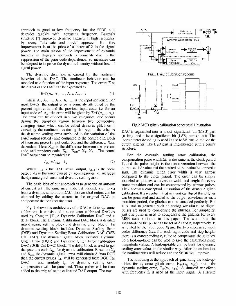
III. SIMULATION RESULTS AND DISCUSSION Fig. 3 DAC test structure illustrationA 15-bit DAC is used to verify the validity of this
approach, Fig 3. The raw DAC is segmented into a 7-bit dynamicyforbranthermometer MSB DAC and a 8-bit binary LSB DAC. An Afterdynamictglitch calideal ADC is used to generate the input code. Since most of 110 AfBothrsdyttnlicngtanldcitthe nonlinearity errors come from the MSB part, so only the 1053 bit upper MSB (UMSB) current sources array are 9 5 0
implemented with transistors level to reflect the 90 enonlinearities in the circuit while the 4 bit low MSB (LMSB) 85-and the 8-bit LSB DAC is AHDL behavior model. 75
70
The calibration is done for several cases: only dynamic 65 _ 160
settling error calibration, only dynamic glitch error 0.1 1 f(MHz) 10 100calibration and both dynamic settling and glitch errorscalibration. Fig. 4 SFDR vs Input signal frequency between before
In order to compensate the dynamic errors, it is better to and after dynamic calibration.calibrate as many bits as possible. But the complexity of the In order to measure the robustness of this approach, thelook-up-table will increase dramatically with the increase in time interval, At, and the delay, Atd, of the pulse used forthe number of calibrated bits. However, the improvement Of glitch compensation are varied.SFDR may be not obvious if the calibration bits number istoo small resulting from insufficient information in the look- 1) SFDR vs Compensation pulse widthup table. So a tradeoff exists between the calibration bits and The nominal value of the compensation current pulsethe complexity. In this paper, the 7-bit MSB (3-bit width is assumed to be 0.4ns, the input signal frequency fo isthermometer transistor level for upper MSB and 4-bit binary about 2MHz. The simulation results are shown in Fig. 5.behavior model for lower MSB) is used for calibration. When the width changes ±0.lns(±25%), the SFDR valueCurrent sources with cascoded structure are used in 3bit changing is about -4dB(-4%). It is within the tolerate range.UMSB to increase the output impedance in order to reduce As it is not difficult to adjust the normalized width withinthe current source drain voltage variation. The clock 500, this results indicates that the compensation pulse widthfrequency f,lk is 200MHz. The dynamic glitch compensation variation has little effect on the SFDR improvement.pulse width is 0.4ns.
2) SFDR vs Compensation pulse delayThe effect of calibration is shown in Fig. 4. From the plot, it In calibration technique, it is assumed that thecan be seen that the SFDR values before and after calibration compensation pulse is aligned with the raw DAC output. Butare close at low frequency. Whereas, a significant increase in it may be not the case in reality. A time difference betweenthe SFDR performance, at least 20dB, can be noticed at the raw DAC output and the calibration pulse, Atd, may exist.higher frequencies when dynamic glitch calibration is taken This delay will have impact on the SFDR. The effect ofinto account. Not much SFDR improvement is achieved by different Atd to SFDR is shown in Fig. 6. In the simulation,having both dynamic glitch calibration and dynamic the compensation pulse width is 400ps, the input signalsettling calibration as compared to only the dynamic glitch frequency is about 11.3MHz. The magnitude of SFDRcalibration as well as the results show that the SFDR decreases from about 98dB to about 87dB when the A\tdimprovement is mainly from the dynamic glitch calibration, changes from 0 to 400ps. If the delay can be control under
A. Robustness ofthe calibration approach 200ps, the degradation of the SFDR is less than about 60%.
119

The requirement of this control is not hard, so it is not a big [7] Bugeja, A.R.; Bang-Sup Song; "A self-trimming 14-b 100-MS/sconcern in the design. CMOS DAC", IEEE J. of Solid-State Circuits, Volume: 35, Issue: 12,
Pages: 1841 - 1852, Dec. 2000.Both results of 1) and 2) show that this approach is
robust.SFDR vs compensation pulse width
B. SFDR vs shape ofcompensation pulse 107In the calibration process, not only the robustness of the 106 -
approach but also implementation possibility is needed to be 105 \considered. In the previous calibration, the pulses used in 104 /calibration are rectangle in shape. In reality, it is a big 103 /challenge to get rectangle waveform with width of half nano 102 isecond. However, it is much easy to generate a triangle or 101_ _
101-near triangle waveform. If the SFDR improvement using 0.2 0.25 0.3 0.35 0.4 0.45 0.5 0.55triangle waveform for compensation can achieve the same or pulse width (ns)just a little bit below as that with rectangle, it will relax therealization of the calibration. Two kinds of triangle Fig. 5 SFDR vs Coinensation ulse widthwaveforms (a) and (b) as shown in Fig. 7 are used to replacethe rectangular waveform, where the height is normalized to SFDR vs Compensation pulse delay afterthe height of the rectangle waveform. The SFDR dynamic clibrationimprovement for different compensation pulse shapes isshown in Fig.8. The results show that the shapes of the 100
triangle have little effect on the SFDR improvement for thesame compensation pulse energy as that of the rectangular m 95pulse.
Only one current pulse is employed for each MSBtransition during the calibration. So the error waveformcaused by dynamic nonlinearity can't be completely 85compensated. If a current array is applied for each MSB td (ps)transition, it will compensate nonlinearities more precisely, Fig. 6 SFDR vs Compensation pulse delaytherefore, achieve a better dynamic performance.
IV. CONCLUSION 2.2
A new approach for dynamic nonlinearity calibration ofDAC was presented. The input code dependence can be I \significantly attenuated and a over 20dB SFDR improvement 4 oin higher frequency is achieved by generating an appropriate 200pS 400ps t 200pS 400pSamount of current pulse and adding it to the raw DAC outputcurrent at each states transition.
Fig. 7 Two calibration triangle waveformsREFERENCES
[1] Rudy van de Plassche, CMOS Integrated Analog-to-Digital and SFDR vs Frequency for different pulse shapeDigital-to-Analog Converters, Norwell, MA, Kluwer, 2003. -Triganle (a) -4-Rectangle
[2] Yong. Cong, "A 1.5-v 14-Bit IOOM-MS/S Self-Calibrated DAC", 105 Beforecal +triangle(b)IEEE, J. of Solid-State Circuits, Volume. 38. No. 12, Dec. 2003. 100
Q2 ~~~~~~~~~~~~~95-[3] Van Der Plas, G.A.M., "A 14-bit intrinsic accuracy Q2 random walk m 90CMOS DAC ", IEEE J. of Solid-State Circuits, Volume: 34 , Issue: 8512, Pages: 1708 - 1718, Dec. 1999. a 80
CO 75-[4] Yong. Cong, "Switching sequence optimization for gradient error 70ecompensation in thermometer-decoded DAC arrays", IEEE Trans. 65Volume: 47, Issue: 7, Pages: 585 - 595, July 2000. 60
[5] O'Sullivan, K.; Gorman, C., "A 12-bit 320-MSample/s current- 1 f (MHz) 10 100steering CMOS D/A converter in 0.44 mm2", IEEE J. Solid-StateCircuits, Volume: 39, Issue: 7, Pages: 1064 - 1072, July 2004. Fig. 8 SFDR vs Input signal frequency for different
[6] Tang, A.T.K.; Toumazou, C., "Self-calibration for high-speed, high-copnainulespsresolution D/A converters", Advanced A-D and D-A ConversioncopnainulespsTechniques and their Applications, 1994. Second InternationalConference on 6-8 July 1994, Pages: 142- 147, July 1994.
120