Dynamic Balancing of Rotating Machinery in the Field · APM-56-19 Dynamic Balancing of Rotating...
9
APM-56-19 Dynamic Balancing of Rotating Machinery in the Field B y E. L. THEARLE,1 SCHENECTADY, N. Y. This paper describes a method and portable equipment for balancing rotating machinery while running under normal operating conditions. A direct and exact solution of the problem is offered, which makes it possible to balance a rotor completely by means of a definite pro- cedure utilizing the data obtained from only three balanc- ing runs of the machine. The system is so developed as to require a minimum of mental effort on the part of the operator. I N RECENT years both the users and manufacturers of rota- tive apparatus have given increasing attention to the matter of vibration elimination. This has resulted in considerable progress in the development of machines and processes for the production balancing of rotating parts in the factory. There exists also the problem of balancing rotating machinery in the field, with the rotor mounted in its own bearings and probably running under normal operating conditions. Machines which have been serviced must often be rebalanced before use. Also, the state of unbalance of a rotor may change, as time goes on, due to the slight shifting of its parts or to the gradual relief of stresses in the shaft or body of the rotor. In such cases, which occur frequently, the cost and delay of disas- sembly, shipment of the rotor to and from a balancing machine, and reassembly are usually prohibitive. Many rotors change shape slightly with changes of running speed, and will therefore show considerable unbalance at their normal running speed even though carefully balanced at some lower speed in a balancing machine. There have recently been built several very large turbo-alter- nators, the alternator field alone weighing over 100 tons, which is too great a weight for any available balancing machine. Such rotors must be balanced in their own bearings. Thus there is a real need for a direct and scientific method of dynamic balancing in the field—one simple of application and utilizing readily portable equipment. The system of balancing to be described was developed in view of this need. Experience with this system indicates that in many cases its use accomplishes a better balance in a shorter time than is realized with the usual balancing machine. There are many possible causes of vibration2 in rotating ma- 1 Research Engineer, General Electric Co. Assoc-Mem. A.S.M.E. Mr. Thearle was graduated from Cornell University, where he served as instructor of applied mechanics from 1920 until 1925. He was professor of mechanical engineering, head of the department, at the University of Arkansas from 1925 until 1928, when he became as- sociated with the Research Laboratory of the General Electric Company. 1 “Turbine Vibration and Balancing,” by T. C. Rathbone, A.S.M.E. Trans., vol. 51, 1929, paper APM-51-23. Contributed by the Applied Mechanics Division for presentation at the Annual Meeting, New York, N. Y., December 3 to 7, 1934, of T he A merican S ociety of M echanical E ngineers . Discussion of this paper should be addressed to the Secretary, A.S.M.E., 29 West 39th Street, New York, N. Y., and will be ac- cepted until January 10, 1935, for publication at a later date. N ote : Statements and opinions advanced in papers are to be understood as individual expressions of their authors, and not those of the Society. chinery other than unbalance. This paper will be limited to a description of means of dealing with that component of vibration which occurs at running-speed frequency, caused by mass un- balance in the rotating member. This is the only component of vibration which may be eliminated by the addition of balance weights to the rotating mass. However, the system and equip- ment here described will not only simplify the elimination of vi- bration at running-speed frequency, but will aid in analysis to determine the causes of vibration at other frequencies. For the present let us simplify the problem by considering a single, substantially rigid, rotating mass mounted in two sup- porting bearings. Many actual machines may be considered as a combination of such units which may be treated separately. It can be shown that, for the correct balance of such a rotor, two weights placed in different radial planes of the rotor are in general necessary and are always sufficient. For the purpose of this illustration, a rotor having a horizontal axis of rotation will be assumed. Such a rotor is represented diagrammatically in Fig. 1. The vibratory motion of any point on either bearing or pedestal may be represented by three components—the horizontal and vertical radial components and the axial component. The purpose of balancing, at any chosen running speed of the rotor, is to reduce the greatest of these three components to a practical minimum. When this is accomplished, the other two compo- nents will also have been reduced and will remain less than that component originally greatest. For the sake of example, it will here be assumed that the horizontal radial component is the greatest; therefore only this component will be dealt with in the analysis. If either one of the other components is the greatest, the procedure is the same except that'measurements are made in the direction corresponding to this greatest component. It follows, in this ideal case, that if the horizontal components of vibration of two points, one chosen on each pedestal, are re- duced to zero, the purpose of balancing has been accomplished and no vibration is transmitted to the structure supporting the rotor. When balancing any substantially rigid rotor there are four variables to be dealt with—the amount and position of each of two corrective weights, to be placed in different radial planes of the rotor, usually one near each end of the rotor as shown in Fig. 1. The farther apart these corrective planes are, the smaller, in general, may be the corrective weights. When balancing such a rotor in a balancing machine, the rotor may be mounted elastically in such a way that it is pivoted to oscillate about some chosen radial axis. If this is done, only two
Transcript of Dynamic Balancing of Rotating Machinery in the Field · APM-56-19 Dynamic Balancing of Rotating...

APM-56-19
Dynamic Balancing of Rotating Machinery
in the FieldB y E. L. THEARLE,1 SCHENECTADY, N. Y.
This paper describes a method and portable equipment for balancing rotating machinery while running under
normal operating conditions. A direct and exact solution of the problem is offered, which makes it possible to balance a rotor completely by means of a definite procedure utilizing the data obtained from only three balancing runs of the machine. The system is so developed as to require a m in im um of mental effort on the part of the operator.
IN RECENT years both the users and manufacturers of rotative apparatus have given increasing attention to the matter of vibration elimination. This has resulted in considerable
progress in the development of machines and processes for the production balancing of rotating parts in the factory. There exists also the problem of balancing rotating machinery in the field, with the rotor mounted in its own bearings and probably running under normal operating conditions.
Machines which have been serviced must often be rebalanced before use. Also, the state of unbalance of a rotor may change, as time goes on, due to the slight shifting of its parts or to the gradual relief of stresses in the shaft or body of the rotor. In such cases, which occur frequently, the cost and delay of disassembly, shipment of the rotor to and from a balancing machine, and reassembly are usually prohibitive.
Many rotors change shape slightly with changes of running speed, and will therefore show considerable unbalance at their normal running speed even though carefully balanced at some lower speed in a balancing machine.
There have recently been built several very large turbo-alternators, the alternator field alone weighing over 100 tons, which is too great a weight for any available balancing machine. Such rotors must be balanced in their own bearings.
Thus there is a real need for a direct and scientific method of dynamic balancing in the field—one simple of application and utilizing readily portable equipment. The system of balancing
to be described was developed in view of this need. Experience with this system indicates that in many cases its use accomplishes a better balance in a shorter time than is realized with the usual balancing machine.
There are many possible causes of vibration2 in rotating ma
1 Research Engineer, General E lectric Co. Assoc-Mem. A .S .M .E .
M r . Thearle was graduated from Corne ll U niversity , where he
served as instructor of applied mechanics from 1920 u n t il 1925. He
was professor of mechanical engineering, head of the departm ent, a t
the U niversity of Arkansas from 1925 u n t il 1928, when he became as
sociated w ith the Research Labora tory of the General E lectric
Com pany.
1 “ Turbine V ibra tion and B a lanc ing ,” by T . C . R a thbone ,
A .S .M .E . Trans., vol. 51, 1929, paper APM-51-23.
C ontribu ted by the Applied Mechanics D iv is ion for presentation
at the A nnua l M eeting , New Y ork , N . Y ., Decem ber 3 to 7, 1934, of
T h e A m e r i c a n S o c ie t y o f M e c h a n i c a l E n g i n e e r s .
Discussion of th is paper should be addressed to the Secretary,
A .S .M .E ., 29 W est 39th Street, N ew Y o rk , N . Y . , and w ill be ac
cepted un til January 10, 1935, for pub lica tion a t a later date.
N o t e : Statem ents and opinions advanced in papers are to be
understood as ind iv idua l expressions of the ir authors, and no t those of
the Society.
chinery other than unbalance. This paper will be limited to a description of means of dealing with that component of vibration
which occurs at running-speed frequency, caused by mass unbalance in the rotating member. This is the only component of vibration which may be eliminated by the addition of balance weights to the rotating mass. However, the system and equipment here described will not only simplify the elimination of vibration at running-speed frequency, but will aid in analysis to determine the causes of vibration at other frequencies.
For the present let us simplify the problem by considering a single, substantially rigid, rotating mass mounted in two supporting bearings. Many actual machines may be considered as a combination of such units which may be treated separately. It can be shown that, for the correct balance of such a rotor, two weights placed in different radial planes of the rotor are in general necessary and are always sufficient. For the purpose of this illustration, a rotor having a horizontal axis of rotation will be assumed. Such a rotor is represented diagrammatically in Fig. 1.
The vibratory motion of any point on either bearing or pedestal may be represented by three components—the horizontal and
vertical radial components and the axial component. The purpose of balancing, at any chosen running speed of the rotor, is to reduce the greatest of these three components to a practical minimum. When this is accomplished, the other two components will also have been reduced and will remain less than that component originally greatest. For the sake of example, it will here be assumed that the horizontal radial component is the greatest; therefore only this component will be dealt with in the analysis. If either one of the other components is the greatest, the procedure is the same except that'measurements are made in the direction corresponding to this greatest component. It follows, in this ideal case, that if the horizontal components of vibration of two points, one chosen on each pedestal, are reduced to zero, the purpose of balancing has been accomplished and no vibration is transmitted to the structure supporting the
rotor.When balancing any substantially rigid rotor there are four
variables to be dealt with—the amount and position of each of two corrective weights, to be placed in different radial planes of the rotor, usually one near each end of the rotor as shown in Fig. 1. The farther apart these corrective planes are, the smaller,
in general, may be the corrective weights.When balancing such a rotor in a balancing machine, the rotor
may be mounted elastically in such a way that it is pivoted to oscillate about some chosen radial axis. If this is done, only two
746 TRANSACTIONS OF THE AMERICAN SOCIETY OF MECHANICAL ENGINEERS
of the four unknown variables (one weight and its position) need be dealt with at once. When balancing a large rotor in its own bearings in the field (or factory) it has been customary to assume that a balance weight on any one end of the rotor influences the vibration of the corresponding pedestal only. This is not the case. Thus when balancing by the method most commonly used heretofore, a weight Wn (Fig. 1) will be found and placed at a certain angular position on the rotor (determined largely by trial and error) such that the nearest pedestal N does not vibrate more than a practical tolerance. Then, similarly, a weight W/ is determined and placed on the rotor in such a position that pedestal F is practically vibrationless.
Returning to pedestal N, it is usually found that the weight W/ has destroyed the previous work done there. Subsequently, further correction at end N destroys the apparent balance obtained at F by weight W/, and so on. With very long rotors it is true that this series may converge fairly rapidly, but the method still involves many expensive trial runs. With some quite short rotors, this series may actually diverge, and balancing by this method becomes impossible. A correct method of balancing in the field must therefore deal simultaneously with four variables—the amount and position of each of two weights. The system to be described here does this by including the effect of each weight on both pedestals or on any other two points chosen on the machine.
R e p r e s e n t a t io n o f V ib r a t io n s b y V e c t o r s
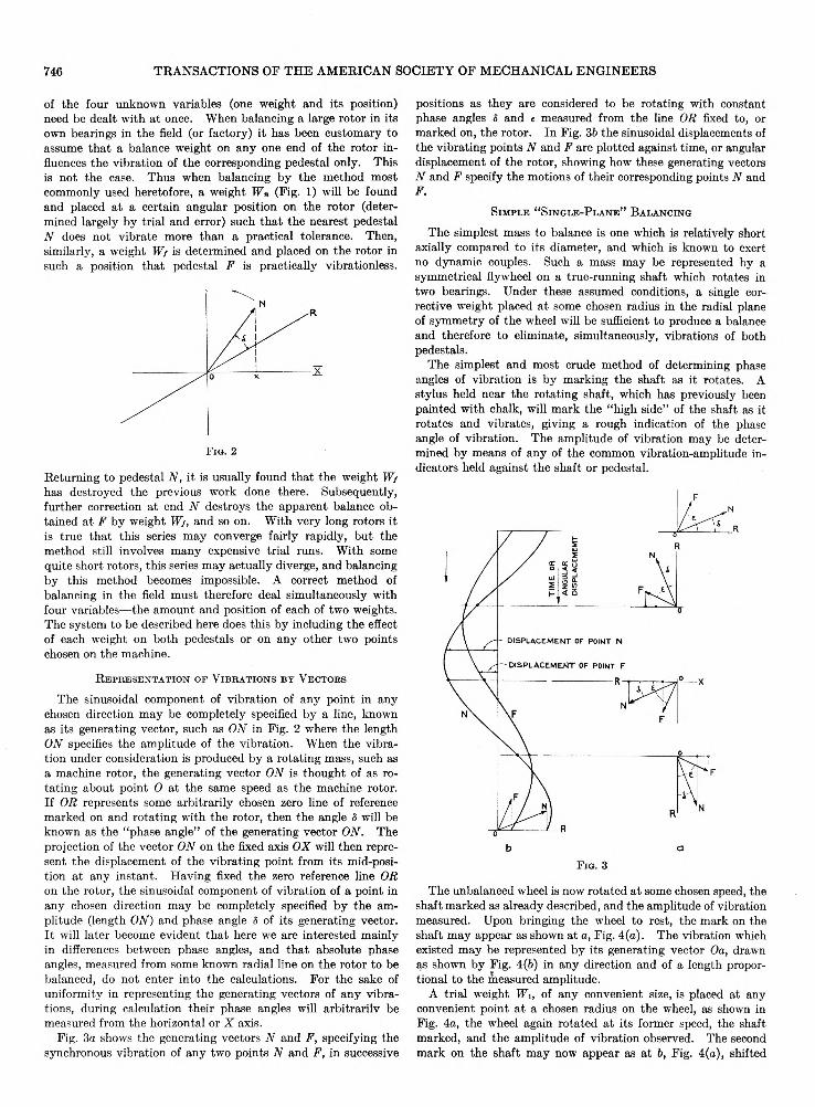
The sinusoidal component of vibration of any point in any chosen direction may be completely specified by a line, known as its generating vector, such as ON in Fig. 2 where the length ON specifies the amplitude of the vibration. When the vibration under consideration is produced by a rotating mass, such as a machine rotor, the generating vector ON is thought of as rotating about point 0 at the same speed as the machine rotor. If OR represents some arbitrarily chosen zero line of reference marked on and rotating with the rotor, then the angle 5 will be known as the “phase angle” of the generating vector ON. The projection of the vector ON on the fixed axis OX will then represent the displacement of the vibrating point from its mid-position at any instant. Having fixed the zero reference line OR on the rotor, the sinusoidal component of vibration of a point in any chosen direction may be completely specified by the amplitude (length ON) and phase angle S of its generating vector. It will later become evident that here we are interested mainly in differences between phase angles, and that absolute phase angles, measured from some known radial line on the rotor to be balanced, do not enter into the calculations. For the sake of uniformity in representing the generating vectors of any vibrations, during calculation their phase angles will arbitrarily be measured from the horizontal or X axis.
Fig. 3a shows the generating vectors N and F, specifying the
synchronous vibration of any two points N and F, in successive
positions as they are considered to be rotating with constant phase angles S and e measured from the line OR fixed to, or marked on, the rotor. In Fig. 3b the sinusoidal displacements of the vibrating points N and F are plotted against time, or angular displacement of the rotor, showing how these generating vectors N and F specify the motions of their corresponding points N and F.
S im p l e “ S in g l e -Pl a n e ” B a l a n c in g
The simplest mass to balance is one which is relatively short axially compared to its diameter, and which is known to exert no dynamic couples. Such a mass may be represented by a symmetrical flywheel on a true-running shaft which rotates in two bearings. Under these assumed conditions, a single corrective weight placed at some chosen radius in the radial plane of symmetry of the wheel will be sufficient to produce a balance and therefore to eliminate, simultaneously, vibrations of both pedestals.
The simplest and most crude method of determining phase angles of vibration is by marking the shaft as it rotates. A
stylus held near the rotating shaft, which has previously been painted with chalk, will mark the “high side” of the shaft as it rotates and vibrates, giving a rough indication of the phase angle of vibration. The amplitude of vibration may be determined by means of any of the common vibration-amplitude indicators held against the shaft or pedestal.
F i g . 3
The unbalanced wheel is now rotated at some chosen speed, the shaft marked as already described, and the amplitude of vibration measured. Upon bringing the wheel to rest, the mark on the shaft may appear as shown at a, Fig. 4(a). The vibration which existed may be represented by its generating vector Oa, drawn as shown by Fig. 4(6) in any direction and of a length proportional to the measured amplitude.
A trial weight Wi, of any convenient size, is placed at any convenient point at a chosen radius on the wheel, as shown in Fig. 4a, the wheel again rotated at its former speed, the shaft marked, and the amplitude of vibration observed. The second
mark on the shaft may now appear as at 6, Fig. 4(a), shifted

APPLIED MECHANICS APM-56-19 747
its resultant effect will be equal in magnitude and opposite in direction to the original vibration vector Oa, and will, therefore, annul the original vibration. This treatment is based upon the assumption that, at the same speed of rotation, vibration am
plitudes are proportional to the unbalanced forces producing them. The assumption is, in general, justified by both theoretical considerations and experience. -The determination of phase angles by shaft marking is not sufficiently accurate to yield very satisfactory results and a more accurate means of measurement
will be described later. The example given, illustrating a method described in the literature before,2 was inserted here simply as an
F ig . 4(6)
aid to the understanding of the complete system of balancing to be presented.
V e c t o r A l g e b r a
The solution of the general balance problem is greatly facilitated by the use of vector algebra. Here we deal with the vectors N, F, A, and B and the vector operators a, (}, 9, and 4>. These vectors and vector operators each have two dimensions, a magnitude and an angle. It is thus necessary to state both the magnitude and the angle in order to specify any one of these quantities.
Writing an operator before any vector indicates the operation of rotating the vector through the angle of the operator and
multiplying the magnitude of the vector by the magnitude of the operator. Thus writing the operator a before the vector A, as aA, produces a new vector aA of magnitude equal to the product of the magnitudes of a and A, and at an angle equal to
the sum of their angles. This new vector aA , therefore, bears a definite angular relation and magnitude ratio to the original vector A, fixed by the operator a.
For example, suppose the vector A is of magnitude 12 units, at an angle of 30 deg, as shown in Fig. 5. The vector A may then be written A = 12 units, 30 deg. The operator a = 0.6, 10 deg, for example, applied to the vector A, gives the new vector aA , such that the magnitude of aA = 0.6 X 12 units = 7.2 units and the angle of aA = 30 deg + 10 deg = 40 deg. Thus the vector aA = 7.2 units, 40 deg, as shown in Fig. 5. This opera-
F ig . 5
tion is written as a multiplication and, as such, follows the common laws of algebra.
Also, a vector may be “divided” by an operator to give a new vector, or a vector may be divided by another vector to determine the operator relating them. Thus for example, if A = 12 units, 30 deg, and a = 0.6, 10 deg, then A / a — C. Hence the magnitude of 0 = 12/0.6 = 20 units, the angle of C = 30 deg — 10 deg = 20 deg, and C = 20 units, 20 deg.
With these same values of A and C, if A /C = a, then the magnitude of a = V2/2G = 0.6, the angle of a = 30 deg — 20 deg = 10 deg, and a = 0.6, 10 deg. The operator A /A = 1 is obviously of magnitude unity, at zero angle. These operations, written as division, also follow the common laws of algebra.
It is felt that vector subtraction, which is the only other opera
tion required here, may be most advantageously accomplished graphically on a polar-coordinate chart prepared for the purpose. For example, suppose A = 12 units, 30 deg, and B = 9 units, 120 deg.
To determine A-B, by subtracting vector B from vector A (see Fig. 6), draw A, 12 units long, at 30 deg, and B, 9 units long, at 120 deg.
Then A-B is the vector drawn from B to A (indicated by
B -+ A ). Its magnitude may be determined by direct measurement. Its angle is determined by drawing the line ba parallel to BA, by means of a parallel ruler, and reading the angle directly at a. Care must be exercised to read the angle corresponding to the vector from B to A rather than that from A to B.
through an angle 5, in a counter-clockwise direction, from its former position. This vibration which took place with the trial weight in place may now be represented by its generating vector 06 drawn, as in Fig. 4(6), displaced an angle S in a counter-clockwise direction from the original vector Oa, and of a length proportional to the last observed amplitude.
The vector ab then represents the change in the vibration
produced by the trial weight Wi. It is then apparent from the diagram of Fig. 4 that if the trial weight Wi, and therefore its effect (vector ab), are displaced through the angle y, and its
magnitude is increased to

748 TRANSACTIONS OF THE AMERICAN SOCIETY OF MECHANICAL ENGINEERS
D u a l -Pl a n e B a l a n c in g
As previously pointed out, the correct balance of a comparatively long and substantially rigid rotor supported in two pedestals, as shown in Fig. 7, in general requires the addition of two corrective weights, one in each of two separate radial planes. The data necessary to determine the amounts and positions of the two corrective weights is obtained in three runs, all at the same chosen balancing speed, by measuring vibration amplitude and phase angle at each of any two chosen points on the machine under each of the following three conditions:
(1) No corrective weights on the rotor(2) Any single known weight, of reasonable amount,
placed at any angular position on the first end of the rotor
(3) Any single known weight of reasonable amount placed at any angular position on the second end of the rotor.
F ig . 7
The first of these three runs determines the generating vectors of the vibrations to be eliminated, and the latter two runs determine the susceptibility of the rotor vibration to individual weights placed in each of its two chosen balancing planes separately.
The apparatus used in making vibration-amplitude and phase- angle measurements, to be described, includes a contactor which is attached to one end of the machine, rotating synchronously with it, and from which phase angles are read directly. (See Fig. 7a.) All readings are made from this station. In this work, the balancing planes, or ends of the rotor, and sides of the machine are distinguished as the near end, the far end, and the right and left sides, as they would appear to an observer stationed
at the contactor and facing the machine. Also, the positive direction of measuring angles is taken as counter-clockwise as it would appear to an observer in the above position. This nomenclature eliminates the confusion incident to the use of the terms front, rear, collector end, commutator end, etc., which are not
universally applicable.It must here be assumed that the vibrating system with which
we are dealing is linear, i.e., vibration amplitudes are proportional to the forces causing them. This is an ideal state usually closely approximated in practise.
Consider now the balancing of such a rotor as shown in Fig. 7a. The rotor is run at some pre-chosen balancing speed and the vibration amplitudes and phase angles are measured at the nearend and far-end points Pn and P/, respectively. These measurements determine the generating vectors of the vibrations which are to be annulled: N at an angle 5 and F at an angle e as laid out in Fig. 7b. This constitutes the first run.
A trial weight W'n of any reasonable amount is then applied at any angular position in the near-end balancing plane. The amount and position of this weight are recorded. The second run is then made, at the same speed as before, and measurements of the amplitudes and phase angles at points P» and P/ are repeated. It will be found that the application of the trial weight W'n has changed the generating vectors of the vibrations at these two points to N 2 and F2 (at angles S2 and «2) as shown in Fig. 7c. The effect of this trial weight on the vibration of the near-end pedestal is then shown by the vector drawn from N to N 2,
(Fig. 7c). (AT — N i) = N 2— N = A
Similarly, the effect of this same weight on the vibration of the far-end pedestal is shown by the vector drawTi from F to Ft, (Fig. 7c). (F — F2) - F2 — F
The vectors N -*■ Ni and F — F2 represent the effects of the same weight W'n. Assuming a linear system (effects proportional to causes) if this weight be increased by any amount, the vectors N —>■ N 2 and F —> F1 will be increased proportionately. Also if the position of this weight on the rotor be shifted through
any angle, these vectors F -* Fi and N — Ni will be turned through the same angle. Thus there is a definite ratio of magnitudes of N —► Ni and F —*■ F2 and a fixed angle between them, independent of the state of balance of the rotor. Therefore, if the vector JV -*■ N2 is written
the vector F —*■ F2 may be written
where a is a vector operator which is a constant characteristic of the machine and its mounting.
The weight W'n is now removed and a trial weight W't of any reasonable amount is applied at any angular position in the far-end balancing plane.
The third run is then made, at the same speed as before, observing the angle and amplitude readings which determine the generating vectors Nz and F3 of the vibrations at the near-end and far-end pedestals, respectively. These vectors are shown in Fig. 7d. The effect of the weight W't on the far-end pedestal may then be represented by the vector
Since the effect N —*■ Ns on the near-end pedestal is due to the same weight W't, this vector may be written
where 0 is a vector operator similar to a.The vectors A, aA, B, and /3B, redrawn in Fig. 7e, specify the
susceptibility of the machine to balance weights. Having determined, in three runs of the machine, the vibrations which it is desired to eliminate and the susceptibility of the machine to weights, we now wish to calculate the final weights Wn and Wi which will give a correct balance.
The trial weights W'n and W't and the final wreights Wn and Wf require a statement of both magnitude and position
(direction) to specify each of them. They are therefore vector quantities and may be treated as such. Each final weight may

APPLIED MECHANICS APM-56-19 749
be derived from its corresponding trial weight by a shift in angle and a multiplication. Thus the two new vector operators 6 and 0 may be introduced such that
and
Assuming vibration amplitudes to be proportional to the forces causing them, any vector operation 9 on a trial weight W'n, for example, will result in the same vector operation on the effects A and aA of that weight.
The statement may now be written that the operations 0 and 4> performed on the trial weights W'n and W’t, respectively, will balance the rotor. This is equivalent to writing the statement that the operators 6 and 4> applied to the effects A, aA, B, and 0B of these trial weights, will produce new effects equal and opposite to the generating vectors N and F of the original vibration.
and
Solving these equations for the operators 8 and 0,
and
It must be remembered that all quantities appearing in Equations [2] and [3] are vector quantities, and that all operations indicated are vector operations as previously defined.
These calculations are most easily made on the standard sheet devised for this purpose, as shown with sample calculations in Fig. 8. On this sheet each step in the calculation is indicated. Vector multiplications and divisions are replaced by their equivalent components appearing only as arithmetic additions, subtractions, multiplications, and divisions. For example, the angle
of a, item 13, is indicated as being found by subtracting item 5 from item 9, (9 — 5). The magnitude of a, item 14, is indicated as (10 -5- 6), found by dividing item 10 by item 6. Vector subtractions are performed graphically. For example, under con-
C a l c u l a t io n s
The calculation of 6 and <t> from [2] and [3] may be made in the following series of steps:

750 TRANSACTIONS OF THE AMERICAN SOCIETY OF MECHANICAL ENGINEERS
struction No. 1, Fig. 8, the values of angle and magnitude of A items 5 and 6, are indicated as direct measurements of the vector N —<• Ni, as drawn, by (5, 6 = N —► Ni). These measurements are made as shown in the preceding section on vector algebra.
The operators 6 and 4> appear as the result of these calculations. For example, item 31, 8, is the angle through which the near-end trial weight should be shifted, in a counter-clockwise direction, to be in the position of the correct final weight. Item 32 is the
number by which this trial weight should be multiplied to give the
amount of the correct final weight. Similarly, items 33 and 34 are the corresponding angle and amount of the operator <t>. Thus operators 8 and <t> determine the corrective weights to be applied to the rotor, and the application of these weights com
pletes the process.
R e f i n e m e n t o p B a l a n c e
Many actual machines will be found to be non-linear. That is, changes in vibration amplitude will not be exactly proportional to the balance weights producing them. For this reason, and because of errors of measurement and calculation, it may be found desirable to refine the balance of a machine after having
completed the process described above.Providing no change in the machine has been made, such as of
speed or means of support, having once completed the above balancing process, requiring three runs, any subsequent re
balancing requires only a single run.After having applied the corrective weights dic
tated by any previous balancing, the machine is again run and new measurements of the vectors N and F are made and recorded on a new calculation sheet. All items on the previous calculation
sheet which are marked with an asterisk may be transferred to the new sheet and the calculations
repeated as before.
M e a s u r e m e n t o f V i b r a t io n
In order to take full advantage of the balancing method here described, instruments have been devised by means of which vibration amplitude and phase angle can be accurately measured. This balancing equipment consists of two generators, a contactor, and a microammeter, with the necessary adaptors and connections. The instruments are set up on a machine to be balanced as shown diagrammatically in Fig. 9. The two generators are identical and are attached to any two points on the machine such as the bearing pedestals, A and B.
Fig. 10 shows a cross-section through one of these generators,
as mounted on a machine pedestal (a) for horizontal vibration. The main body of the generator is a permanent-magnetic-field structure (6), annular in form, suspended by the springs (c). The central tube (d) is carried by two flat springs (e) which maintain rigid radial alignment, but permit easy axial motion, of the tube relative to the field (fe). The tube (d) carries the coil (/),
in the gap of the magnetic circuit, and is caused to vibrate with the machine pedestal, by means of the slender rod (g).
In order to maintain ruggedness of design, the flat springs (e) must be so stiff axially that the natural frequency of vibration of coil relative to magnetic field would not differ sufficiently from the frequency of vibration of some low-speed machinery. If this generator were used on low-speed machinery, the field structure would not remain substantially stationary in space, and the mo
tion of the coil relative to the field would not be a true measure of the vibration of the machine pedestal.
To avoid this difficulty, the mechanism at the end of
the instrument serves as a “negative spring” to balance
the positive stiffness of the flat springs (e) and thus
lower the natural frequency of vibration of the instrument
without sacrifice of ruggedness. The notched blocks (j) are fixed to the magnetic field of the generator by means of the flat springs (h). The adjustable notched ring (m) is fixed, to the central tube (d) carrying the coil. The stiff struts (k) pivot in the notches of the blocks (j ) and the
ring (m), and are loaded by means of the adjustable springs (n). An axial displacement of the tube (d) and coil, relative to the field, thus tilts the struts and introduces a “negative” restoring force, substantially proportional to the displacement. By adjustment of the tension in the springs (n) this negative restoring force may be made approximately equal to the positive restoring force exerted by the flat springs (e), thus reducing the natural frequency of vibration of the instrument to a very low value and making it suitable for use on low-speed machinery.
When one of these generators is attached to a vibrating machine, the field structure of the instrument remains practically stationary in space while the coil vibrates with the machine and generates an alternating electromotive force proportional to the velocity of this vibration. If true vibration indications are to be obtained, the suspension of the instrument as described is quite necessary because of the great difficulty in finding a truly stationary point on any building or structure surrounding a vibrating machine.
Fig. 11 shows the external appearance of a generator arranged
for horizontal vibration. Fig. 12 shows a generator mounted on the pedestal of a 35,000-kw turbine. For dealing with the vertical component of a vibration, the instrument is mounted as shown in Fig. 13.
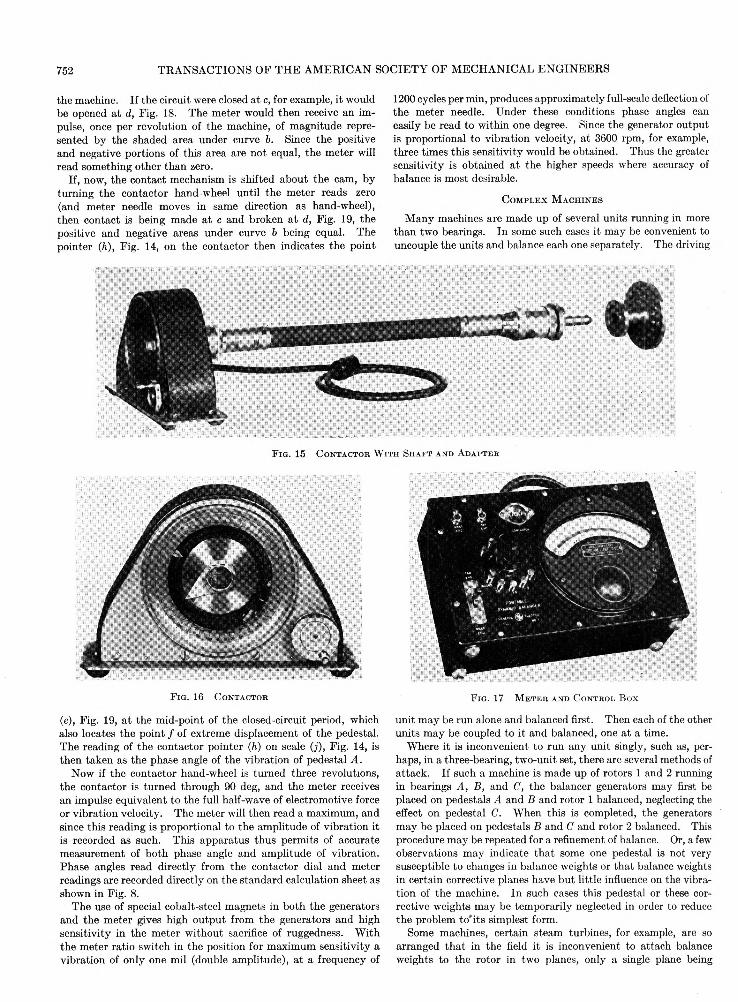
The contactor mechanism is shown diagrammatically in Fig. 14. An adapter (a) is fixed to the end of the machine shaft (6) by means of three small screws. A clutch (c) is arranged so that the contactor may be connected to or disconnected from the machine, while it is running, without losing the angular relation between machine and contactor. The cam (e), driven through

APPLIED MECHANICS APM-56-19 751
the flexible shaft (Vi), maintains the contact (/) closed during 180 deg of each revolution of the machine, and open the remaining half revolution. The contact mechanism (J) may be turned about the axis of the cam by means of the handwheel (g). The pointer (h), from which phase angles of vibration are read directly on the scale (j), is fixed to the disk which carries the contact mechanism (/), and moves with it. The pointer (fc), which rotates with the cam, is only a convenience when attaching trial weights to the machine and is not essential. The hand-wheel (g) is geared to the contact mechanism (J) in the ratio of twelve to one, so that three revolutions of the hand-wheel shifts the phase angle of contact 90 deg. Since only angular differences are used in the balancing calculations, no predetermined angular relation between the cam and machine rotor need be observed when attaching the contactor adapter to the machine shaft. Fig. 15 shows the complete contactor and adapter, disconnected. The face of the contactor is shown in Fig. 16.
o
F i g . 11 G e n e r a t o r f o r P o r t a b l e D y n a m i c B a l a n c e r
(Mounted for horizontal vibration.)
The meter is a highly damped, direct-current microammeter as shown in Fig. 17. It is arranged with a tumbler switch for connecting to either generator and a ratio switch giving meter readings in the ratio of 1, 3, 10, and 30 so that the most suitable scale may be used for any vibration amplitude to be dealt with. Leads from the two generators and the contactor plug into the meter box.
Consider now the operation of these units when
brought together on a machine to be balanced, and connected as shown in Fig. 9 with, for example, the switch thrown to the generator on pedestal A. Referring to Fig. 18, curve a represents the sinusoidal displacement of pedestal A during its vibration.The vibration velocity is the first derivative of curve a which is shown as curve b. Vibration velocity is also sinusoidal; it is zero when displacement is a maximum and is a maximum when displacement
is zero, as shown by curve b. Since the electromotive force induced in the generator coil is proportional to vibration velocity, and since meter current is proportional to it, curve b may represent the meter current which would flow if the circuit through the meter were continuously closed. However, the contactor maintains the circuit closed only during one half of each revolution of
F i g . 12 B a l a n c e r G e n e r a t o r M o u n t e d o n B e a r i n g P e d e s t a l
o f 3 5 ,0 0 0 K w S t e a m - T u r b in e G e n e r a t o r
F ig . 13 G e n e r a t o r f o r P o r t a b l e D y n a m i c B a l a n c e r
(Mounted for vertical vibration.)
752 TRANSACTIONS OF THE AMERICAN SOCIETY OF MECHANICAL ENGINEERS
the machine. If the circuit were closed at c, for example, it would be opened at d, Fig. 18. The meter would then receive an impulse, once per revolution of the machine, of magnitude represented by the shaded area under curve 6. Since the positive
and negative portions of this area are not equal, the meter will read something other than zero.
If, now, the contact mechanism is shifted about the cam, by turning the contactor hand-wheel until the meter reads zero (and meter needle moves in same direction as hand-wheel), then contact is being made at c and broken at d, Fig. 19, the positive and negative areas under curve b being equal. The pointer (h), Fig. 14, on the contactor then indicates the point
1200 cycles per min, produces approximately full-scale deflection of the meter needle. Under these conditions phase angles can easily be read to within one degree. Since the generator output is proportional to vibration velocity, at 3600 rpm, for example, three times this sensitivity would be obtained. Thus the greater sensitivity is obtained at the higher speeds where accuracy of balance is most desirable.
C o m p l e x M a c h in e s
Many machines are made up of several units running in more than two bearings. In some such cases it may be convenient to uncouple the units and balance each one separately. The driving
F i g . 15 C o n t a c t o r W i t h S h a f t a n d A d a p t e r
F i g . 16 C o n t a c t o r
(e), Fig. 19, at the mid-point of the closed-circuit period, which also locates the point / of extreme displacement of the pedestal. The reading of the contactor pointer (h) on scale (j ), Fig. 14, is then taken as the phase angle of the vibration of pedestal A.
Now if the contactor hand-wheel is turned three revolutions, the contactor is turned through 90 deg, and the meter receives an impulse equivalent to the full half-wave of electromotive force or vibration velocity. The meter will then read a maximum, and since this reading is proportional to the amplitude of vibration it is recorded as such. This apparatus thus permits of accurate measurement of both phase angle and amplitude of vibration. Phase angles read directly from the contactor dial and meter readings are recorded directly on the standard calculation sheet as
shown in Fig. 8.The use of special cobalt-steel magnets in both the generators
and the meter gives high output from the generators and high sensitivity in the meter without sacrifice of ruggedness. With the meter ratio switch in the position for maximum sensitivity a vibration of only one mil (double amplitude), at a frequency of
F i g . 17 M e t e r a n d C o n t r o l B o x
unit may be run alone and balanced first. Then each of the other units may be coupled to it and balanced, one at a time.
Where it is inconvenient to run any unit singly, such as, perhaps, in a three-bearing, two-unit set, there are several methods of attack. If such a machine is made up of rotors 1 and 2 running in bearings A, B, and C, the balancer generators may first be placed on pedestals A and B and rotor 1 balanced, neglecting the effect on pedestal C. When this is completed, the generators
may be placed on pedestals B and C and rotor 2 balanced. This procedure may be repeated for a refinement of balance. Or, a few observations may indicate that some one pedestal is not very susceptible to changes in balance weights or that balance weights in certain corrective planes have but little influence on the vibration of the machine. In such cases this pedestal or these corrective weights may be temporarily neglected in order to reduce the problem to'its simplest form.
Some machines, certain steam turbines, for example, are so arranged that in the field it is inconvenient to attach balance weights to the rotor in two planes, only a single plane being

APPLIED MECHANICS APM-56-19 753
available in which to apply a corrective weight. In such cases a compromise balance is sought by applying the simple vector method of calculation, as shown in Fig. 4, to vibration observations made at each end of the machine. In this way a single
F i q . 18
F i g . 19
balance weight may be determined which will result in minimum vibration amplitudes.
Relatively long and slender rotors may cause some difficulty in balancing due to distortion. This may usually be overcome by
treating the balancing corrections as two components—a couple component and a force or so-called “static” component. The latter is distributed along the length of the rotor, thus reducing its deflection.
C o n c l u s io n
Only the basic system has been described. Space will not per
mit a discussion of the many variations which are most suited to particular types of machines.
Experience with this balancing system in both the factory and the field has demonstrated its usefulness. In the factory, an effective balancing machine may be had by attaching the balancing generators to almost any pair of bearings in which a rotor
can be run at constant speed. For example, in the manufacture of some electrical machines, all rotors must be run at normal
F i q . 2 0 P o r t a i i l e B a l a n c i n g E q u i p m e n t i n C a r r y i n g C a s e
speed in a machine for grinding their commutators. Applying the balance generators to the grinder pedestals permits the balancing operation to be completed in the same machine.
High sensitivity of the instruments for measuring vibration eliminates the necessity of balancing a rotor in very flexibly mounted bearings which amplify the vibration amplitudes. This high sensitivity, together with a sound method of interpreting the data, provide a means of obtaining better results in less time than can be realized with the ordinary balancing machine.