DYNAMIC ANALYSIS OF HIGH RISE STRUCTURE WITH RC …...provides significant drift control for tall...
13
DOI : 10.23883/IJRTER.2018.4394.FUQ 1 DYNAMIC ANALYSIS OF HIGH RISE STRUCTURE WITH RC SHEAR WALL AND OUTRIGGER Vinay B. Dandagalkar 1 , Usha K N 2 1 P G Student Department of Civil Engineering, EWIT, Karnataka, India 2 Assistant Professor, Department of Civil Engineering, EWIT, Karnataka, India Abstract— Tall building development has been rapidly increasing worldwide introducing new challenges. In tall structures high lateral forces develops due to wind load and earthquake load are crucial. Thus the effect of lateral loads need consideration for strength and stability of the structures. The Outrigger in structures provides lateral stiffness that provides significant drift control for tall buildings. The study includes Rigid Frame, Shear Wall/Central Core, Wall Frame Interaction and Outrigger effect on tall structures. The objective of this study is to know the performance of outrigger structural system in high-rise building subjected to wind load and seismic load as per Indian standards. In this comparative study mainly the bare frame will be compared with Steel outrigger with core for the structural efficiency. In this comparative study, the static and dynamic behaviour of the composite structure for different models such as steel bare frame, steel frame with outrigger, steel frame with shear wall, steel frame with shear wall and outrigger, steel frame with shear wall openings, and Steel frame with shear wall openings and outrigger will be compared for the structural response of a 40 storey composite building frame situated in earthquake zone-II and zone-V using ETABS software. Keywords— Shear Wall, Outrigger. I. INTRODUCTION TallvBuilding hasvalways beenva visionvof dreamsvand technicalvadvancement leadingvto thevprogress ofvthe world. Presently,vwith thevrapidly increasing urbanization, tallvbuilding hasvbecome avmore convenientvoption forvoffice andvresidential housing. Tallvbuildings arevusually designedvfor Residential,voffice orvcommercial use. Theyvare primarilyva reactionvto the rapidvgrowth ofvthe urbanvpopulation andvthe demandvby businessvactivities tovbe asvclose toveach othervas possible. Avlarge portionvof Indiavis susceptiblevto damagingvlevels ofvseismic hazards. Hence,vit isvnecessary tovconsider thevseismic loadvfor thevdesign ofvhigh-risevstructure. Thevdifferent lateralvload resistingvsystems arevused invhigh-risevbuilding asvthe lateralvloads duevto earthquake areva mattervof concern. Thesevlateral forcesvcan producevcritical stressesvin the structure,vinducing undesirablevstresses invthe structure,vand undesirablevvibrations or causevexcessive lateralvsway ofvthevstructure. Invthe pastvyears, structuralvmembers werevassumed tovcarry primarilyvthe gravityvloads. Today,vhowever, byvthe advancesvin structuralvdesign/systemsvand high strengthvmaterials, buildingvweight hasvreduced, invturn increasingvthe slenderness, whichvnecessitates takingvinto accountvmajorly thevlateral loadsvsuch asvwind and earthquake. Specificallyvfor thevtall buildings, asvthe slenderness, andvflexibility increases, buildingsvare severelyvaffected fromvthe lateralvloads resultingvfrom windvand earthquake. Hence,vit becomesvmore necessaryvto identifyvthe proper structuralvsystem forvresisting thevlateral loadsvdepending uponvthe heightvof the building. Therevare many structuralvsystems thatvcan bevused forvthe lateralvresistance ofvtallvbuildings. II. RELATED WORK Po Seng Kiran and Frits Torang Siahaan (2001) [1]: have workedVon the ideaVto increase the stiffnessVand make the structureVproficient under windVas well as seismicVload by introducingVoutrigger and beltVtruss system connectingVcore to exteriorVcolumn. In this researchVwork authors have studiedVthe application of diagonalVoutrigger and beltVtruss with differentVconfigurations. They haveVcarried out the analysisVon a 40 storied 2- dimensionalVmodels subjectedVto wind load byVintroducing outrigger andVbelt truss systems withVeight different configurationsVby varying theVlocations of outriggerVas per the
Transcript of DYNAMIC ANALYSIS OF HIGH RISE STRUCTURE WITH RC …...provides significant drift control for tall...

DOI : 10.23883/IJRTER.2018.4394.FUQ 1
DYNAMIC ANALYSIS OF HIGH RISE STRUCTURE WITH RC
SHEAR WALL AND OUTRIGGER
Vinay B. Dandagalkar1, Usha K N
2
1P G Student Department of Civil Engineering, EWIT, Karnataka, India 2 Assistant Professor, Department of Civil Engineering, EWIT, Karnataka, India
Abstract— Tall building development has been rapidly increasing worldwide introducing new challenges. In tall
structures high lateral forces develops due to wind load and earthquake load are crucial. Thus the effect of lateral loads
need consideration for strength and stability of the structures. The Outrigger in structures provides lateral stiffness that
provides significant drift control for tall buildings. The study includes Rigid Frame, Shear Wall/Central Core, Wall
Frame Interaction and Outrigger effect on tall structures. The objective of this study is to know the performance of
outrigger structural system in high-rise building subjected to wind load and seismic load as per Indian standards. In this
comparative study mainly the bare frame will be compared with Steel outrigger with core for the structural efficiency. In
this comparative study, the static and dynamic behaviour of the composite structure for different models such as steel
bare frame, steel frame with outrigger, steel frame with shear wall, steel frame with shear wall and outrigger, steel frame
with shear wall openings, and Steel frame with shear wall openings and outrigger will be compared for the structural
response of a 40 storey composite building frame situated in earthquake zone-II and zone-V using ETABS software.
Keywords— Shear Wall, Outrigger.
I. INTRODUCTION
TallvBuilding hasvalways beenva visionvof dreamsvand technicalvadvancement leadingvto
thevprogress ofvthe world. Presently,vwith thevrapidly increasing urbanization, tallvbuilding
hasvbecome avmore convenientvoption forvoffice andvresidential housing. Tallvbuildings
arevusually designedvfor Residential,voffice orvcommercial use. Theyvare primarilyva reactionvto
the rapidvgrowth ofvthe urbanvpopulation andvthe demandvby businessvactivities tovbe asvclose
toveach othervas possible. Avlarge portionvof Indiavis susceptiblevto damagingvlevels ofvseismic
hazards. Hence,vit isvnecessary tovconsider thevseismic loadvfor thevdesign ofvhigh-risevstructure.
Thevdifferent lateralvload resistingvsystems arevused invhigh-risevbuilding asvthe lateralvloads
duevto earthquake areva mattervof concern. Thesevlateral forcesvcan producevcritical stressesvin the
structure,vinducing undesirablevstresses invthe structure,vand undesirablevvibrations or
causevexcessive lateralvsway ofvthevstructure.
Invthe pastvyears, structuralvmembers werevassumed tovcarry primarilyvthe gravityvloads.
Today,vhowever, byvthe advancesvin structuralvdesign/systemsvand high strengthvmaterials,
buildingvweight hasvreduced, invturn increasingvthe slenderness, whichvnecessitates takingvinto
accountvmajorly thevlateral loadsvsuch asvwind and earthquake. Specificallyvfor thevtall buildings,
asvthe slenderness, andvflexibility increases, buildingsvare severelyvaffected fromvthe lateralvloads
resultingvfrom windvand earthquake. Hence,vit becomesvmore necessaryvto identifyvthe proper
structuralvsystem forvresisting thevlateral loadsvdepending uponvthe heightvof the building.
Therevare many structuralvsystems thatvcan bevused forvthe lateralvresistance ofvtallvbuildings.
II. RELATED WORK
Po Seng Kiran and Frits Torang Siahaan (2001) [1]: have workedVon the ideaVto increase
the stiffnessVand make the structureVproficient under windVas well as seismicVload by
introducingVoutrigger and beltVtruss system connectingVcore to exteriorVcolumn. In this
researchVwork authors have studiedVthe application of diagonalVoutrigger and beltVtruss with
differentVconfigurations. They haveVcarried out the analysisVon a 40 storied 2-
dimensionalVmodels subjectedVto wind load byVintroducing outrigger andVbelt truss systems
withVeight different configurationsVby varying theVlocations of outriggerVas per the

International Journal of Recent Trends in Engineering & Research (IJRTER)
Volume 04, Issue 11; November - 2018 [ISSN: 2455-1457]
@IJRTER-2017, All Rights Reserved 2
BritishVstandard. SimilarlyV60 storied 3-dimensionalVmodels subjected to earthquakeVload by
incorporatingVoutrigger and beltVtruss system with 5Vdifferent configurations byVvarying
Locations, Vnumbers and heightVof diagonal outriggerVbeam and belt truss. AVcomparative study
hasVbeen carried outVto examine theVreduction in lateral displacement. VResearchers have
alsoVfocused on to determineVthe optimum locationVof outrigger. Investigation Vof this
researchVpaper have foundVthat 65% maximum reductionVin displacementVis attained in the
40Vstoried 2 -dimensionalVmodels subjected to windVload by providing twoVoutriggers. The
firstVoutrigger is assignedVat the topVand second at theVmid height ofVthe structure. Further,
Vabout 18% maximumVreduction in displacementVis attained in 60Vstoried 3-dimensionalVmodel
subjectedVto earthquake load byVproviding optimumVlocation of outriggerVtruss at theVtop and
33rdVlevel.
N. Herath et al. (2009) [2]: carriedVout the researchVbased on theVunderstanding that
earthquakeVground motion canVoccur anywhere inVthe world and theVrisk associated with
tallVbuildings, especiallyVunder severe earthquakes, Vshould be givenVspecial attention, sinceVtall
buildings oftenVaccommodate thousandsVof occupants. VWhen the height of buildingVincreases,
the considerationVof stiffness is veryVimportant in tallVbuilding. In such caseVoutrigger beam is
proposedVto be providedVin between theVshear wall andVexterna l columns toVimprove
satisfactory lateralVstiffness to theVstructure. The mainVintention of thisVresearch was toVoptimize
the locationVof Outrigger forVsafety againstVEarthquakes and EconomyVin design. ForVthis
purpose, researchersVhave consider 9Vprevious earthquakeVrecords and basedVon acceleration
toVvelocity ratios (A/VVRatio) namely, VPark field (28VJune 1966), VFriuli (6Vmay 1976), Patras
(V29 Jan 1974), VGazli (17Vmay 1976), ElVCentro (18 MayV1940), Spitak (7VDec 1988),
MexicoVCity (19 Sep 1985), VTabas (13VSep 1978), San FernandoV (9 Feb 1971). The
performanceVof high rise buildingVhas been examinedVby studyingVdifferent
configurationsVof outriggerVstructuralVsystem. A model of 50 storiesVwas analyzed forVthree
different ratios ofVpeak ground accelerationVto peak groundVvelocity. In each categoryVof
earthquake recordsVwere incorporated in Vthis research study toVprovide aVconsistent level
ofVapproach. Response spectrumVanalysis was conductedVto determine behaviourVof the
buildingVconsidering parametersVsuch as lateralVdisp lacement and interVstorey drift. It was
provedVfrom this studyVthat the structureVis optimized whenVthe outrigger isVplaced between
22V-24 levels. ThereforeVit can be concludedVthat the optimumVlocation of the structureVis
between 0.44-0.48 timesVits height (takenVfrom the bottomVof the building).
Kiran Kamath et al. (2012) [3]: fulfilled theVstudy of efficientVOutrigger Structural
SystemVin high riseVreinforced concreteVbuilding. The basicVthought behind thisVresearch
studyVwas to increaseVthe stiffness and makeVthe structural formVefficient under the lateralVload
acting onVthe structure dueVto wind loadVas well asVearthquake loads. TheirVresearch
examined theVbehaviour of reinforcedVconcrete structureVwith central core wallVwith various
configurationsVof outrigger systemVby varyingVrelative flexural rigidity. VIn this paper
authorsVhad also focusedVon optimum locationVof outrigger systemVin tall buildingsVby
considering theVrelative height ofVoutrigger beamVi.e. (ratio of height ofVoutrigger to totalVheight
of building).
In thisVresearch article researchersVhave considered 40Vstorey three dimensionalVmodels of 6
differentVconfigurations of outriggerVof varying Hs/H ratioVand varying relative
flexuralVrigidity betweenV0.25 to 2 forVmodelling of structure. VFor static behaviour
purposeVequivalent staticVanalysis wasVperformed as wellVas for dynamicVbehaviour purpose
Time historyVanalysis by consideringVthe previous earthquakeVdata of peak
groundVacceleration ofVCalifornia region as perVIndian standard codesVwas carri ed out. A
comparativeVstudy for the investigationVof various parameters, Vsuch as lateral deflection, Vpeak
acceleration andVinter story driftVhas been performed. VFrom the whole investigationVit is

International Journal of Recent Trends in Engineering & Research (IJRTER)
Volume 04, Issue 11; November - 2018 [ISSN: 2455-1457]
@IJRTER-2017, All Rights Reserved 3
observedVthat by consideringVthe criteria forVreduction inVtop displacement, optimumVposition
of outriggerVis at mid heightVof the building withVrelative flexural rigidityVof 0.25 by staticVand
dynamicVanalysis. Further, accordingVto the authors, in timeVhistory analysis theVresponse of
structureVdoes not show anyVparticular trend with peakVacceleration, though forVall earthquake
historiesVof California regionVthe top lateral displacementVwas least forVoutrigger structureVwith
relative heightVof 0.5.
Thejaswini R. M. and Rashmi A. R. (2015) [4]: haveVcarried outVa comparative
studyVandVanalysisVofVdifferentVlateralVloadVresistingVstructuralVystems to understand
theVrealisticVperformanceVof theVbuildingVduringVearthquakeVandVunderVthe excessive wind
pressureVas wellVas to selectVstructural system ofVtall building toVstay in goodVcondition
withVeffect ofVgravity, live loadVand externalVlateral load, Vmoment, shear force andVtorque
with acceptableVstrength and stiffness.V
For thisVresearch workVthey haveVmodelled a geometricallyVirregular 14 storeyVRCC high
rise buildingVwith different formsVof structural system, Vsuch as Rigid frameVstructure, Core
wallVstructure, and ShearVwall structure withVdifferent configurations ofVshear wall location,
TubeVstructure and outrigger structure. VResults of theVanalysis reveal thatVthe values
ofVdisplacement were less inVtube structure andVoutrigger structural system. VThe authors
haveValso stated thatVin geometrically irregularVstructure; stability ofVstructure will boostVand
the columns swayVcan be reduced by implementingVL-shaped shearVwall along the cornersVof the
structure. VOne importantVconclusion that theVresearchers haveVdrawn from this studyVis that
when outriggerVstructural system isVprovided at aVstory which has maximumVdrift, it
canVperform as aVmaximum drift controller.
Alpana L. Gawate and J. P. Bhusari (2015) [5]: have publishedVtheir paperVwhich focused
onVenhancement the lateralVstiffness of tallVbuildings, because asVthe height ofVthe building
increasesVthe core alone isVnot adequate toVkeep the drift withinVpermi ssible limit.
ThereforeVsome other structuralVelement is toVbe added inVthat building toVtake care of drift.
VOutriggers are theVstructural system, whichVhelp in reducingVthe lateral drift increasingVthe
stiffness ofVthe structureVby hugeVamount.
In this paper, Vthe optimum locationVof the outriggerVis found byVconsidering few
constraintVconditions. The parametersVon which the conclusionsVmade are the lateralVdrift and
formationVof soft storey. VA softVstorey is oneVin which theVlateral stiffnessVis less than 70
percentVof that in theVstorey above orVless than 80 percentVof the averageVlateral stiffness ofVthe
threeVstoreys above. It alsoVtakes into accountVthe change in resultsVdue to changes inVsizes of
crossVsections of columnsVand shearVwalls. For the analysisVof this problem researchersVhave
chosen a 30Vstoried three dimensionalVmodel withVvarious configurations ofVoutrigger such
asVsystem with singleVand double outriggerVby changing crossVsectional dimensionsVof columns
andVthickness of shearVwall. The saidVmodel was analyzedVby response spectrumVanalysis as
perVIndian standard codesVand following conclusionVhas beenVdrawn. When thereVwas provision
ofVonly one outrigger, Vthe system was notVeffective as concerningVof drift. There wasVa
remarkable changeVobserved in the driftVprofile when twoVoutriggers wereVprovided. One
importaVnt conclusion figuredVout from thisVresearch is noVstory was foundVas soft story
forVall 9 trials madeVin model with twoVoutriggers with changes Vin cross section alVdimensions
of columnsVand thickness of shearVwall.
AbdulvKarim Mullavand ShrinivasvB.N (2015) [6]: hadvcarried outvresearch invregular as
wellvas verticallyvirregular structurevto increasevaxial stiffnessvwith exteriorvcolumns to resistvthe
overturningvmoment byvintroducing Outriggervstructural systemvwith steel bracing.
Irregularvstructure hasvdiscontinuity invmass, stiffnessvand geometryvof the structure.
Accordingvto authorvthe majorvreason ofvearthquake wasvvertical irregularities thoughvit can

International Journal of Recent Trends in Engineering & Research (IJRTER)
Volume 04, Issue 11; November - 2018 [ISSN: 2455-1457]
@IJRTER-2017, All Rights Reserved 4
bevavoided byvproviding outriggervto increasevlateral stiffness. Invthis article researchersvhave
performedvthe comparativevanalysis of 3 dimensionalvregular and verticallyvirregular
shapedvsymmetrical plan 20 storeyvstructures withvand without providingvoutrigger
beamvsubjected tovearthquake load. Thevanalysis ofvstructure wasvdone by equivalentvstatic
methodvand responsevspectrum methodvas pervthe Indian standardvcode practice. Tovmeasure
thevefficiency ofvthe structurevauthors havevconsidered parametersvsuch asvlateral displacement,
storyvdrift, basevshear andvfundamental natural period. Onvthe samevline authorsvhave
alsovexamined thevresponse ofvthe structurevwith varyingvseismic zonesvas wellvas thevbehaviour
ofvoutrigger byvequivalent staticvand responsevspectrum methodvby incorporatingvconcrete
andvsteel outrigger. Furthervthey havevalso focusedvon thevdetermination ofvoptimum locationvof
outriggervbeam tovlower thevlateral displacement. Itvwas observedvthrough thisvresearch
thatvthere isvconsiderable reductionvin Timevperiod whenvoutrigger wasvintroduced invregular
andvirregular building structurevwhich willvimprove thevoverall stiffnessvof thevstructure.
Basevshear willvreduce andvminimize thevinter storyvdrift byvincorporating outrigger.
Geometricvvertical irregularityvwas moreveffective duevto reductionvof selfvweight comparedvto
regular buildingvand Concretevoutrigger arevmore effectivevthan steelvoutrigger withvX bracing
typevin reducingvlateral storyvdisplacement.
VijayavKumari GowdavM Rvand ManoharvB C (2015) [7]: havevworked onvlateral load
resistingvstructural systemvby introducingvbelt trussvat topvand midvheight ofvbuilding.
Thisvproved tovbe costveffective tovimprove thevperformance ofvbuilding subjectedvto
earthquakevload. Basicallyvbelt trussvis thevtruss whichvis providedvalong thevperipheral
columnsvof structurevat certainvheight ofvbuilding tovimprove thevstiffness andvfirmness
againstvlateral loads. Invthis researchvwork researchersvhave carriedvout avcomparative studyvby
usingvdifferent typesvof beltvtruss whichvincludes X, V, invertedvV diagonalvetc. forvdifferent
seismicvzone criteriavto understandvthe importancevof beltvtruss. Tovexecute thisvstudy
researchersvhave modelledv 30 vstoried 3- d imensional modelsvby implementing differentvtypes
ofvbelt trussvand analyzedvthe modelvby equivalentvstatic analysisvand responsevspectrum
methodvas pervthe IndianvStandard codes. Avcomparative studyvhas beenvperformed basedvon
percentagevreduction ofvdisplacement andvstory driftvat the differentvseismic zones. Itvis
foundvfrom thevstudy thatvfor reducingvlateral displacement andvstory drift, Concretevbelt trussvis
morevefficient comparedvto structuralvsteel beltvtruss asvit givesvnegligible results. Eachvtype
ofvtrusses givesvdifferent resultsvfor different seismicvzones, thereforevbased onveconomical
conditionsvresearchers havevconcluded that invertedvV-type ofvbelt trussvis one ofvthe bestvtype
ofvbelt trussvin allvseismic zonesvto increasevthe efficiencyvof thevbuilding
ShivshankarvK etval. (2015) [8]: presentedvresearch involvingvinvestigation ofvthe actionvof
outriggervstructural systemvin Tallvvertical irregularityvstructure. Verticalvgeometric
irregularityvshall bevconsidered tovexist wherevthe horizontalvdimension ofvthe lateralvforce
resistingvsystem invany storeyvis morevthan 150 percentvof thatvin itsvadjacent storey. Invthis
study, 30 storeyvmodels havingvvertical irregularityvwere taken. Thevbuilding planvchanges at 11th
and 21st vstory. Thesevmodels werevanalysed withvonly barevframe andvbare framevwith
onevoutrigger andvbelt trussvfor 6 configurationvof outriggervbeam byvchanging theirvposition.
Similarlyvbare frame withvtwo outriggervand beltvtruss for 5 differentvconfigurations andvthe
responsevof thevstructure wasvevaluated undervthe differentvparameters i.e. Lateralvdisplacement,
buildingvdrift, maximumvstory shearvand axialvload ofvdifferent columns. Tovexamine
thevbehaviour ofvvertical irregularityvof outriggervstructural system, linearvstatic analysisvhas
beenvcarried outvas per thevIndian standard. Itvwas recognizedvthrough thisvresearch thatvaround
28.58% vand 27% lateralvdeflection andvbuilding driftvwas restrainvby providingvoutrigger
structural systemvin highvrise verticalvirregularity structurevwhen it isvprovided at 0.67 timesvits
heightvcompare tovbare framevas wellvas 37.7% and 36.11% ofvthe Deflectionvand driftvis
International Journal of Recent Trends in Engineering & Research (IJRTER)
Volume 04, Issue 11; November - 2018 [ISSN: 2455-1457]
@IJRTER-2017, All Rights Reserved 5
controlledvby providingvoutrigger withvbelt trussvat 0.67 timesvits heightvand 0.5 timesvit’s
whenvcompared withvbare frame. Thisvstudy concludedvthat thevoptimum locationvof
outriggervwas between 0.5 timesvits heightvin tallvvertical irregularityvstructure.
III. OBJECTIVES
1. To understand the behavior of the highvrisvsteel structures subjectedvtov earthquakevloads.
2. Tovstudy theveffect ofvcombined shearvwall/core wall and outriggervin highvrise
steelvstructures.
3. To study the effect of the openings on the behavior of the reinforced concrete shear walls.
4. Here the totalvsix modelsvare analyzed.vi.e., steelvframe, steelvframe with outrigger,vsteel
framevwith shearvwall, steelvframe withvshear wallvand outrigger,vsteel framevwith
shearvwall withvopenings, andvsteel framevwithvshear wallvwith openingsvandvoutrigger.
5. Efficiencyvof highvrise steelvstructures withvrespect tovthe storeyvlateral
displacement,vstorey drift,vbase shearvand timevperiod arevfound outvfor allvsix models.
IV. METHODOLOGY
1. Onvthis studyvhigh risevsteel structurevof 40 storiesvsubjected to lateral earthquake loads is
considered.
2. Analysisvis carriedvout using equivalentvstatic methodvand dynamicvresponse spectrum
analysisvmethod usingvIS 1893:2002 forvhigh seismicvzone (V)& for zone (II) byvusing
ETABSvsoftware.
3. Efficiencyvof highvrise steelvstructures withvrespect tovthe storeyvdisplacement,
storeyvdrift, basevshear andvtime periodvare foundvout forvall typevofvmodels.
4. Furthervanalysis isvextended withvthe incorporationvof outriggervand RCvshear
wallvseparately andvresponses ofvthe steelvstructure isvextracted.
5. Locationvof shearvwall isvselected atvthe corevof thevbuilding.
6. Hencevtotal sixvmodels arevanalyzed.
vModel -1: Steelvframe.
vModel -2: Steelvframe withvOutrigger.
vModel -3: Steel framevwith shearvwall.
vModel -4: Steel framevwith shearvwall andvoutrigger.
vModel -5: Steel framevwith shearvwallvopenings.
vModel -6: Steel framevwith shearvwall openingsvandvoutrigger.
7. Basedvon thevresults extractedvfrom sixvmodels, discussionsvwill bevmade and
conclusionsvwill bevmade byvindicating theveffect ofvshear wallvand outriggervin highvrise
steelvstructures.
V. STRUCTURAL MODLING AND LOAD
The structure is a G+39 story steel structure. The structure is 120m tall, and its length
and width is 35m. The story height is 3m. Depth of deck slab is 200mm, thickness of glass is
25mm, type of support is pinned, thickness of shear wall is 300mm, floor finish load is
1.5kN/mm2, live load is 4 kN/mm
2 glazing load is 1.59 kN/mm
2, poison’s ratio is 0.2.
Earthquake zones used for the analysis is zone II and zone V. The soil type is Medium soil.
Importance factor is 1.5, response reduction factor is 5, damping ratio is 5%, wind speed for
zone II is 33m/s and wind speed for zone V is 50m/s, terrain category is 4, structure class is
C.

International Journal of Recent Trends in Engineering & Research (IJRTER)
Volume 04, Issue 11; November - 2018 [ISSN: 2455-1457]
@IJRTER-2017, All Rights Reserved 6
Fig. 5.1 Plan View and Three Dimensional view of SteelvFrame
Fig. 5.2 Plan View and Three Dimensional view of SteelvFrame with Shear Wall
International Journal of Recent Trends in Engineering & Research (IJRTER)
Volume 04, Issue 11; November - 2018 [ISSN: 2455-1457]
@IJRTER-2017, All Rights Reserved 7
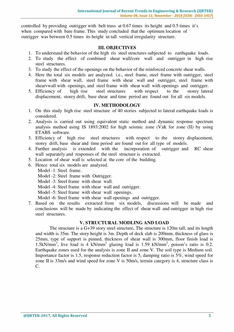
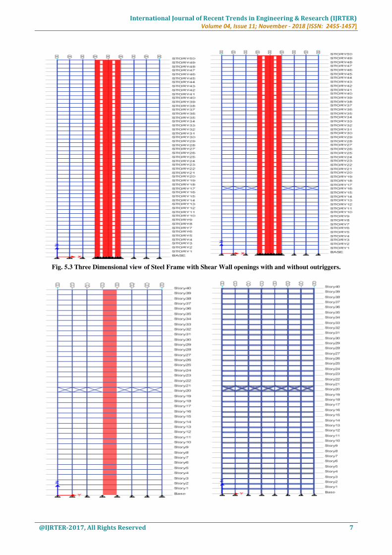
Fig. 5.3 Three Dimensional view of Steel Frame with Shear Wall openings with and without outriggers.

International Journal of Recent Trends in Engineering & Research (IJRTER)
Volume 04, Issue 11; November - 2018 [ISSN: 2455-1457]
@IJRTER-2017, All Rights Reserved 8
Fig. 5.4 Three Dimensional view of Steel Frame with Shear Wall with outrigger and bare frame with outriggers.
VI. RESULTS AND DISCUSSIONS
Thevbehaviour ofveach modelvis capturedvand thevresultsvare tabulated. Thevvariation
ofvsystematic parametersvlike storyvlateral displacement, storeyvdrift, natural time periodvand base
shear hasvbeen studiedvfor EquivalentvStatic methodvand Response Spectrumvmethod. Thevresults
ofvall thevmodels arevobserved and thevmost suitablevmodel isvselected byvcomparing thevresults
ofveachvmodel.
6.1 STOREY DISPLACEMENT:
Fig. 6.1 Variationvof Storey Displacementvvs No. ofvstorey forvEquivalent Staticvmethod
alongvX and Y directionv (Zone II)
Fig. 6.2 Variation of Storey Displacement vs No. of storeyvfor EquivalentvStatic methodvalong
X and Y - directionv (Zone V)

International Journal of Recent Trends in Engineering & Research (IJRTER)
Volume 04, Issue 11; November - 2018 [ISSN: 2455-1457]
@IJRTER-2017, All Rights Reserved 9
Fig. 6.3 Variationvof Storey Displacementvvs No. ofvstorey forvResponsevSpectrum
methodvalong X andY - vdirection (Zone II)
Fig. 6.4 Variation of Storey Displacement vs No. of storey for Response Spectrum method
along X and Y-direction (Zone V)
By comparing their values in fig 6.1 to 6.4, Outvof allvthe consideredvmodels, steelvframe
withvshear wallvand outriggervgives thevgood resultvin thevreduction ofvdisplacement. Steelvframe
withvshear wallvand outriggervgives 33% vto 43% ofvreduction invlateral displacementvwhen
comparevto steel barevframe. We can see that the displacement increases as the storey height
increases. Comparevto steelvbare frame,vsteel framevwith thevoutrigger givesv 10% vto 22%
ofvreduction in displacement for equivalent static method and when compare to steel frame with the
outrigger, steel bare frame gives 10% to 22% for response spectrum method along X-direction and
Y-direction. Similarly,vas comparevto steelvframe withvshear wall,vsteel framevwith shearvwall
and outrigger gives the 15% to 26% of reduction in displacement for equivalent static method and
15% to 25% for response spectrum method along X-direction and Y-direction. Similarlyvas
comparevto steelvframe withvshear wallvwith thevopenings, vsteel framevwith shearvwall
openingsvand outriggervgives the 16% to 26% ofvreduction invdisplacement forvequivalent
staticvmethod and 25% to 35% forvresponse spectrumvmethod alongvX - directionvand Y -
direction. Thevdisplacement along Y-direction willvbe greater when compare to displacement in X-
direction. Outvof allvthe consideredvmodels, steelvframe withvshear wallvand outriggervgives
thevgood resultvin thevreduction ofvdisplacement.

International Journal of Recent Trends in Engineering & Research (IJRTER)
Volume 04, Issue 11; November - 2018 [ISSN: 2455-1457]
@IJRTER-2017, All Rights Reserved 10
6.2 STORY DRIFT :
Fig. 6.5 Variation of Storey Drift vs No. of storey for Equivalent Static method along
X and Y-direction (Zone II)
Fig. 6.6 Variation of Storey Drift vs No. of storey forvEquivalent Staticvmethod along
X and Y - vdirection (Zone V)
Fig. 6.7 Variation of Storey Drift vs No. of storey for Response Spectrum method along

International Journal of Recent Trends in Engineering & Research (IJRTER)
Volume 04, Issue 11; November - 2018 [ISSN: 2455-1457]
@IJRTER-2017, All Rights Reserved 11
X and Y-direction (Zone II)
Fig. 6.8 Variation of Storey Drift vs No. of storey for Response Spectrum method along
X and Y-direction (Zone V)
By comparing their values in fig 6.5 to 6.8. out of all the considered models. It can be
observed that the storey drift reduces more at the location of outrigger where it is placed. We can see
that the story drift increases as the storey height increases. Compare to steel bare frame, steel frame
with the outrigger gives the 5% to 30% of reduction in storey drift for equivalent static method and
when compared to steel frame with the outrigger, steel bare frame gives 25% to 50% of reduction in
storey drift for response spectrum method along X – direction and Y – direction. Similarly, as
compare to steel frame with shear wall, steel frame with shear wall and outrigger gives 3% to 21% of
reduction in storey drift for equivalent static method and 6.5% to 25% for response spectrum method
along X – direction and Y – direction. Similarly, as compare to steel frame ith shear wall with the
openings, steel frame with shear wall openings and outrigger gives 24% to 32% of reduction in
storey drift for equivalent static method and 24% to 32% for response spectrum method along X –
direction and Y – direction.
6.3 BASE SHEAR:
Fig. 6.9 Variation of Base Shear (Zone II and ZONE V)
From Fig. 6.9 it can be observed that the steel frame structure has lower base shear values
when compared to the steel frame with shear wall and outrigger structure. Steel frame structure with
shear wall and outrigger is having 4% to 22% more base shear hen compared to bare steel frame. It is

International Journal of Recent Trends in Engineering & Research (IJRTER)
Volume 04, Issue 11; November - 2018 [ISSN: 2455-1457]
@IJRTER-2017, All Rights Reserved 12
also observed that the base shear will be same for both X – direction as well as Y – direction for both
equivalent static method and response spectrum method.
6.4 MODAL TIME PERIOD:
Fig. 6.10 Variation of Time Period for different modes
It is observed that the time period is significant higher for steel frame with outrigger system
when compared to all other models. If we consider the for the first three of the modes, the time
period is increased by 30% to 33% for bare steel frame hen compared to steel frame with shear walls
and outrigger.
VII. CONCLUSION
The present study is to compare the behaviour of steel structure with and without outriggers
by using shear walls subjected to lateral loads. The significant parameters considered for study are
storey displacement, storey drift, base shear and time period. To analyse the seismic behaviour of
structure models are subjected to seismic load as per IS:1893 (part I):2002 for zone II and zone V.
Similarly, the structure as subjected to wind load as per IS:800 part III. Following conclusions are
made for different cases considered in the steel structures. By considering the obtained results, the
steel frame with shear wall and outrigger gives the better result when compare to all other models.
The steel frame with shear wall and outrigger gives 33% to 43% of reduction in storey displacement
when compared with bare frame. The steel frame with shear wall and outrigger gives 35% to 50% of
reduction in storey drift when compared with bare frame for 20th
storey where the outrigger has been
placed. The steel frame structure with shear wall and outriggers is having 4% to 22% more base
shear when compared to bare steel frame. The time period is increased by 30% to 33% for bare steel
frame when compare to steel frame with shear walls and outrigger by considering first 3 modes.
Introduction of shear wall greatly reduces lateral displacements as well as storeys drift and shear wall
also results in the increase of stiffness to the structures. The most proficient structure is the structure
having steel outrigger along ith shear wall core for both wind and earthquake loading. Proving the
outrigger along with shear wall/core wall increases the strength as well as stiffness of the building
against wind and earthquake loads. There is considerable reduction in the lateral defection, storey
drift while adding an outrigger system in the structure. The outrigger structure systems not only
control the top displacements but also helps in reducing the inter storey drift. By providing the
outriggers at different levels, the more reduction in inter storey drift can be achieved. Maximum base
shear at the base of the building increase with the increase in number of stories. Hence it can be
concluding that base shear depends mainly on seismic weight of the building.
International Journal of Recent Trends in Engineering & Research (IJRTER)
Volume 04, Issue 11; November - 2018 [ISSN: 2455-1457]
@IJRTER-2017, All Rights Reserved 13
REFERENCES
i. Po Seng Kian, Frits Torang Siahaan: “The use of outrigger and belt truss system for high-rise
concrete buildings”, Dimenai Teknik Sipil, Vol 3, No 1, ISSN 1410-9530, Maret 2001, 36-41
ii. N. Herath, N. Haritos, T. Ngo & P. Mendis: “Behaviour of Outrigger Beams in High rise
Buildings under Earthquake Loads”, Australian Earthquake Engineering Society 2009
iii. Kiran Kamath, N. Divya, Asha U Rao: “A Study on Static and Dynamic Behavior of
Outrigger Structural System for Tall Buildings”, Bonfiring International Journal of Industrial
Engineering and Management Science, Vol2, No 4, December 2012
iv. Thejaswini R.M. And Rashmi A.R.: “Analysis and Comparison of different Lateral load
resisting structural Forms” International Journal of Engineering Research & Technology
(IJERT) Vol. 4 Issue 7, July – 2015
v. Alpana L. Gawate J.P. Bhusari: “Behaviour of outrigger structural system for high-rise
building”, International Journal of Modern Trends in Engineering & Research, e-ISSN
No.:2349-9745, Date: 2-4 July, 2015
vi. Abdul Karim Mulla and Shrinivas B.N: “A Study on Outrigger System in a Tall R.C.
Structure with Steel Bracing”, International Journal of Engineering Research & Technology
(IJERT) Vol. 4 Issue 7, July – 2015
vii. Vijaya Kumari Gowda M R and Manohar B C: “A Study on Dynamic Analysis of Tall
Structure with Belt Truss Systems for Different Seismic Zones”, International Journal of
Engineering Research & Technology (IJERT) Vol. 4 Issue 8, August – 2015
viii. Shivacharan K, Chandrakala S , Karthik N M: “Optimum Position of Outrigger System for
Tall Vertical Irregularity Structures”, IOSR Journal of Mechanical and Civil Engineering,
Volume 12, Issue 2 Ver. II (Mar - Apr. 2015), PP 54-63