Dynamic analysis of coupled train - ladder track - elevated … · As a new type of vibration...
18
Structural Engineering and Mechanics, Vol. 47, No. 5 (2013) 661-678 DOI: http://dx.doi.org/10.12989/sem.2013.47.5.661 661 Copyright © 2013 Techno-Press, Ltd. http://www.techno-press.org/?journal=sem&subpage=8 ISSN: 1225-4568 (Print), 1598-6217 (Online) Dynamic analysis of coupled train - ladder track - elevated bridge system He Xia 1,2 , Yushu Deng 1,2,3 , Chaoyi Xia 1,2 , G. De Roeck 2 , Lin Qi 4 and Lu Sun 5 1 School of Civil Engineering, Beijing Jiaotong University, Beijing 100044, China 2 Department of Civil Engineering, KU Leuven, B 3001 Leuven, Belgium 3 CCCC Railway Consultants Co. Ltd., Beijing, China 4 TESS Corporation Ltd., Tokyo, Japan 5 School of Transportation, Southeast University, Nanjing 210018, China (Received December 14, 2012, Revised July 16, 2013, Accepted August 16, 2013) Abstract. As a new type of vibration reduction, the ladder track system has been successfully used in engineering. In this paper, a numerical model of the train-track-viaduct system is established to study the dynamic responses of an elevated bridge with ladder track. The system is composed of a vehicle submodel, a track submodel and a bridge submodel, with the measured track irregularities as the system self-excitation. The whole time histories of a train running through an elevated bridge with 3× 27m continuous PC box girders are simulated. The dynamic responses of the bridge such as deflections, lateral and vertical accelerations, and the vehicle responses such as derailment factors, offload factors and car-body accelerations are calculated. The calculated results are partly validated through the comparison with the experimental data. Compared to the common slab track, adapting the ladder sleeper can effectively reduce the accelerations of the bridge girder, and also reduce the car-body accelerations and offload factors of the train vehicle. Keywords: ladder track; elevated bridge; vibration isolation; numerical simulation; dynamic response 1. Introduction The emergence and development of elevated rail transit has delivered us a rapid and convenient traffic medium, while at the same time caused some new problems. Since the elevated rail transit systems run in urban regions, and often through city downtowns and residential areas, they may induce serious environmental vibrations and noises (Takemiya and Bian 2007, Lombaert and Degrande 2009). In recent years, the consideration of the environmental influences of traffic-borne vibrations becomes more and more important in designing and planning traffic systems (Xia et al. 2007). Problems concerning the vibration influence of elevated railway and rail transit system on the environment have been considered by Chen et al. (2007), Andersen et al. (2007), Ju and Lin (2008), He et al. (2010), Kawatani et al. (2010), Yang and Yau (2011). The dynamic behavior of railway bridges subjected to moving trainloads is one of the important problems in bridge design and maintenance. Fundamental theories for the dynamics of bridge structures under moving trains have been developed by a number of researchers, such as the Corresponding author, Professor, E-mail: [email protected]
Transcript of Dynamic analysis of coupled train - ladder track - elevated … · As a new type of vibration...

Structural Engineering and Mechanics Vol 47 No 5 (2013) 661-678
DOI httpdxdoiorg1012989sem2013475661 661
Copyright copy 2013 Techno-Press Ltd
httpwwwtechno-pressorgjournal=semampsubpage=8 ISSN 1225-4568 (Print) 1598-6217 (Online)
Dynamic analysis of coupled train - ladder track - elevated bridge system
He Xia12 Yushu Deng123 Chaoyi Xia12 G De Roeck2 Lin Qi4 and Lu Sun5
1School of Civil Engineering Beijing Jiaotong University Beijing 100044 China
2Department of Civil Engineering KU Leuven B 3001 Leuven Belgium
3CCCC Railway Consultants Co Ltd Beijing China
4TESS Corporation Ltd Tokyo Japan
5School of Transportation Southeast University Nanjing 210018 China
(Received December 14 2012 Revised July 16 2013 Accepted August 16 2013)
Abstract As a new type of vibration reduction the ladder track system has been successfully used in engineering In this paper a numerical model of the train-track-viaduct system is established to study the dynamic responses of an elevated bridge with ladder track The system is composed of a vehicle submodel a track submodel and a bridge submodel with the measured track irregularities as the system self-excitation The whole time histories of a train running through an elevated bridge with 3times27m continuous PC box girders are simulated The dynamic responses of the bridge such as deflections lateral and vertical accelerations and the vehicle responses such as derailment factors offload factors and car-body accelerations are calculated The calculated results are partly validated through the comparison with the experimental data Compared to the common slab track adapting the ladder sleeper can effectively reduce the accelerations of the bridge girder and also reduce the car-body accelerations and offload factors of the train vehicle
Keywords ladder track elevated bridge vibration isolation numerical simulation dynamic response
1 Introduction
The emergence and development of elevated rail transit has delivered us a rapid and convenient
traffic medium while at the same time caused some new problems Since the elevated rail transit
systems run in urban regions and often through city downtowns and residential areas they may
induce serious environmental vibrations and noises (Takemiya and Bian 2007 Lombaert and
Degrande 2009) In recent years the consideration of the environmental influences of traffic-borne
vibrations becomes more and more important in designing and planning traffic systems (Xia et al
2007) Problems concerning the vibration influence of elevated railway and rail transit system on the
environment have been considered by Chen et al (2007) Andersen et al (2007) Ju and Lin (2008)
He et al (2010) Kawatani et al (2010) Yang and Yau (2011)
The dynamic behavior of railway bridges subjected to moving trainloads is one of the important
problems in bridge design and maintenance Fundamental theories for the dynamics of bridge
structures under moving trains have been developed by a number of researchers such as the
Corresponding author Professor E-mail hxia88163com
He Xia Yushu Deng Chaoyi Xia G De Roeck Lin Qi and Lu Sun
analytical solutions by Fryacuteba (1999) Yau and Fryacuteba (2007) Xia et al (2011) and the stochastic
solutions by Li and Zhu (2010) Numerical models of coupled train-bridge dynamic systems
together with experimental validations and engineering applications in high-speed railways and
elevated urban rail transits have been studied by Tanabe et al (2003) Yang and Lin (2005) Wang et
al (2010) Martiacutenez-Rodrigo (2010) Yang et al (2010) Au et al (2011) Shih et al (2011) Romero
et al (2012) Rezvani et al (2013) Guo et al (2013) Zhai et al (2013a b) among others Based on
these studies the vertical and lateral dynamic responses of bridge structures and the safety and
stability of train vehicles during transit have been studied and many useful results were obtained
and reported However most of the studies were carried out for structures with common tracks
whereas little research has been done for structures with vibration mitigation tracks
Many kinds of reduction measures have been studied for railway tracks in China and abroad
such as the floating slab track (Hussein et al 2006 Hui and Ng 2009) the ballast mats (Alves Costa
et al 2012) the isolated track (Guigou-Carter et al 2006 Auersch 2008) the tuned mass dampers
(Wang et al 2003) and others (Xin and Gao 2011 Galviacuten et al 2010) The effects of these isolation
measures have been studied by theoretical analysis numerical calculations and field experiments
The ladder track as a new reduction track which has been used in Japan and America is one of them
(Wakui and Matsumoto 2002 Tahira and Miyahara 2003) Several theoretical analyses and
engineering applications proved that the ladder track system with properties of light-weight
sufficient and effective elasticity low maintenance and low cost is an ideal track system that can
effectively reduce vibration and noise of the track while keeping good train running safety and
stability (Wakui et al 2002 Okuda et al 2003 Xia et al 2010)
In this paper a dynamic analysis model is developed for the coupled train ladder track and
elevated bridge system based on the authorsrsquo previous work (Xia et al 2010 2011) The
train-track-bridge model is composed of the vehicle submodel with each 2-bogie 4-axle vehicle
27-DOFs the ladder track submodel with rails fasteners ladder sleeper and elastic isolators and the
bridge submodel with girders piers and foundations By applying the measured track irregularities
as the self-excitations for the train-track-bridge system the equations of motion are established and
a computer code is developed The proposed framework is then applied to a real elevated bridge with
327 m continuous PC girders The full time histories of the train traversing the bridge are
simulated from which the dynamic responses of the vehicle the ladder track and the bridge are
obtained and discussed
2 Elastically-supported ladder track system
The Elastically-supported ladder track is a new type of low-noise and low-vibration track system
which consists of ladder sleepers L-shaped reinforced concrete bases resilient isolators and buffer
pads made of polyurethane damping materials The ladder sleeper as shown in Fig 1 is a
ladder-shaped structure consisting of twin longitudinal PC beams and transverse steel-pipe
connectors The transverse steel-pipe connectors are rigidly connected with the longitudinal beams
which ensure the required track-gauge
The ladder sleeper is supported through the resilient isolators and the transverse buffer-pads by
the L-shaped RC bases to reduce the vibration spreading on the bridge girder and to mitigate the
structure noise as shown in Fig 2 The transverse buffer-pads are also meant for keeping the
transverse stability of the sleeper The longitudinal forces of the sleeper are resisted by the slots on
the vertical arms of the L-shaped RC bases through the convex stoppers on the longitudinal beams
662
Dynamic analysis of coupled train - ladder track - elevated bridge system
Fig 1 Ladder sleeper with longitudinal PC beams and steel-pipe connectors
Convex stopper Transverse buffer-pad Slot
Steel-tube connector Fastener
Resilient isolator (interval 125 m) Longitudinal
buffer-pad
L-s
hap
ed R
C b
ase
Rai
l
Lo
ng
itu
din
al R
C b
eam
Fig 2 Formation of the elastically-supported ladder track system
To Taipingzhuang
Station Measurement section
3times27m 3times30m
To Taipingzhuang
North Station
Fig 3 The trial section of elevated bridge with ladder track on Metro Line 5 in Beijing
and longitudinal buffer-pads to prevent the sleepers from creeping The longitudinal PC beams can
be regarded as the secondary longitudinal beams in addition to the rails thus the rails together with
the longitudinal PC beams are bearing the train load so forming a composite track with high
stiffness and thus increasing the performance of load dispersion (Deng et al 2007)
The ladder track system has been successfully used in several subways and elevated bridges in
Japan and has been installed in trial sections in America In China a ladder track trial section with a
full length of 171 m has been established on the elevated bridge of the Beijing Metro Line 5 The
trial section crosses two straight lined continuous PC box girders with a 3times30m span and a 3times27m
span as shown in Fig 3 On the bridge the down-line (to the Taipingzhuang North Station) adopts
663
He Xia Yushu Deng Chaoyi Xia G De Roeck Lin Qi and Lu Sun
To Taipingzhuang North
To Taipingzhuang
Slab track
Ladder track
Fig 4 The ladder track on the elevated bridge (the other line is common slab track)
cY
tY
wY
Zb
Ybb
1h
2h
3h
4h
c cm J
t tm J
w
w
m
J2a
cZ
wZ
tZ
c
t
w
y y
2 2k c
2 2z zk c
y
1k
1
zk
1
zc
1
yc
2b
e
ds2
shk
svkshcsvc
rhc
rhk
rvcrvk
Sleeper beam
Rail
Steel-pipe
connector
L-shaped RC base
Bridge deck
Fig 5 The train-ladder track-bridge system model
the common slab track and the up-line (to the Taipingzhuang Station) adopts the ladder track as
shown in Fig 4
3 Dynamic analysis model of coupled train-ladder track-bridge system
The dynamic model for the train-track-bridge interaction is a system composed of the train
submodel the ladder track submodel and the bridge submodel as shown in Fig 5 (left) In the track
model the stiffness and damping of rail-pad are modeled by springs kr and dampers cr and the
buffer-pad and isolators of the ladder sleepers by ks and dampers cs with the subscripts v and h
representing the vertical and lateral direction respectively as shown in Fig 5 (right) The track
irregularities are considered as the internal self-excitation for the system
31 Vehicle model The vehicle model is a train composed of a series of cars Each car is a multi-DOF
(Degree-of-Freedom) vibration system composed of car-body bogies and wheel-sets Each car-body
or bogie considers five DOFs of lateral rolling yawing floating and pitching movements and each
664
Dynamic analysis of coupled train - ladder track - elevated bridge system
1iNv
Fsv1 Fsv2 Fsv3 Fsvk FsvN
x0
0 x
dx
v
Fsv(k+1)
Zr
Yr
Fwvij
Fwhij
Fshk
Fsvk
Fig 6 Forces acting on the rail
wheel-set considers three DOFs of lateral rolling and floating For a rail transit car with two bogies
and four wheel-sets there are 27 DOFs considered in the calculation
The dynamic equations of the vehicle system can be expressed in matrix form as
v v v v v v v+ + =M X C X K X F (1)
where Mv Cv and Kv are the mass damping and stiffness matrices Xv is the displacement vector
and Fv the force vector acting on the train vehicles respectively Details of the vehicle model can be
found in Xia et al (2011)
32 Track model For the ladder track system consisting of rails fasteners ladder sleeper and transverse
connectors the vibration model of the system is composed of the rail on which the train moves and
the ladder sleeper with a large mass The dynamic equations of the track system can be expressed in
matrix form as
t t t t t t t+ + =M X C X K X F (2)
where Mt Ct and Kt are the mass damping and stiffness matrices Xt is the displacement vector and
Ft the force vector acting on the track system respectively
321 Rails The real rail is supported on sleepers via rail-pads which is modeled as an Euler beam with
infinite length discretely supported by springs and dampers Suppose there are Nv cars moving along
the rail with a speed V the forces acting on the rail is illustrated in Fig 6 where o-x represents the
rail coordinate and o-x the moving coordinate of the cars
For the rail owing to its small cross section only the vertical and lateral movements Zr and Yr are
considered as shown in Fig 6 The motion equations of them can be expressed as
665
He Xia Yushu Deng Chaoyi Xia G De Roeck Lin Qi and Lu Sun
Frvk
Frhk
Fbhl
Fbvl
Fhm
Fig 7 Forces acting on a ladder sleeper element
v4 2 4
r r rrz r r wv w sv4 2
1 1 1
( ) ( ) ( )( )δ( ) ( )δ( )
N N
ij ij k k
i j k
Z x t Z x t Z x tEI m c F t x x F t x x
tx t
(3)
v4 2 4r r r
ry r r wh w sh4 21 1 1
( ) ( ) ( )( )δ( ) ( )δ( )
N N
ij ij k k
i j k
Y x t Y x t Y x tEI m c F t x x F t x x
tx t
(4)
where EIry and EIrz are respectively the vertical and lateral bending stiffnesses mr is the mass per
unit length and cr is the damping coefficient of the rail N= NstimesNu Ns is the number of ladder
sleepers considered Nu is the number of rail-pads on each ladder sleeper Fwvij and Fwhij are
respectively the vertical and lateral forces acting on the rail by the j-th wheel-set of the i-th car and
Fsvk and Fshk are respectively the vertical and lateral forces reacting on the rail of the k-th rail-pad
322 Ladder sleeper According to its isolation principle the ladder track belongs to two-level-isolation system the
rubber rail pad (elastic fastener) isolation between the sleeper beam and the rail and the resilient
isolator between the sleeper beam and the L-shaped base In the analysis model both the rubber pad
and the resilient isolator are regarded as spring-damper elements For the ladder sleeper the two
longitudinal PC beams are modeled as Euler beams in the vertical plane while in the lateral
direction the twin longitudinal PC beams and the transverse steel connectors form a frame
Illustrated in Fig 7 are the forces acting on the ladder sleeper In the figure Frvk and Frhk are
respectively the vertical and lateral forces of the k-th fastener rubber pad on each longitudinal beam
caused by the relative displacement between the rail and the sleeper Fbvl and Fbhl are respectively
the vertical and lateral forces of the l-th resilient isolator on each longitudinal beam caused by the
relative displacement between the sleeper and the base (bridge deck) Fhm is the resistance of the
m-th transverse buffer-pad caused by the lateral relative displacement between the sleeper and the
base (bridge deck)
The degrees-of-freedoms considered for the i-th ladder sleeper are the vertical movements of the
two longitudinal beams LsiZ and R
siZ the lateral movement Ysi and the yawing movement si of the
whole sleeper frame Thus the motion equations of the i-th ladder sleeper can be written as
u d4 L 2 L Ls s s
s s s s rv bv4 21 1
( ) ( ) ( )( ) ( )
N Ni i i
k ik l il
k l
Z x t Z x t Z x tE I m c F x x F x x
tx t
(5)
666
Dynamic analysis of coupled train - ladder track - elevated bridge system
V 1 Nv
(2)
sv ilF(1)
sv ilF(1)
sh ilF (2)
sh ilF
(1)
vkP (2)
vkP
(1)
hkP(2)
hkP
sdsh
ph
bY
bZ
b
pd
e
Fig 8 Forces acting on the bridge girder
u d4 R 2 R Rs s s
s s s s rv bv4 21 1
( ) ( ) ( )( ) ( )
N Ni i i
k ik l il
k l
Z x t Z x t Z x tE I m c F x x F x x
tx t
(6)
d
L R L Rs s rh rh bh bh h
1 1 1
( ) ( )u hN N N
i k k l l m
k l m
M Y F F F F F
(7)
u u d dN N N NL R L R
s s rh s rh s bh s bh s
1 1 1 1
1 1 1 1φ F ( ) F ( ) F ( ) F ( )
2 2 2 2i k ik k ik l il l il
k k l l
J x l x l x l x l
h h
L Rh s h s
1 1
1 1( ) ( )
2 2
N N
m im m im
m m
F x l F x l
(8)
where Ms Js and ls are respectively the mass yawing moment of inertia and length of each ladder
sleeper Nu Nd and Nh are respectively the numbers of rubber pads resilient isolators and transverse
buffer-pad on each ladder sleeper
33 Bridge model Illustrated in Fig 8 are the forces acting on the bridge girder induced by the moving train
vehicles No external forces are considered
In the figure Fsvil and Fhvil represent respectively the vertical and lateral forces from the l-th
isolator of the i-th sleeper on the bridge girder which are opposite to Fbvil and Fbhil They are
expressed as follows
(1) (1) (1)sv sv s b b s b sv s b b s b( ) ( ) ( ) ( ) ( ) ( )il i il il i il ilF k Z x t Z x t e d c Z x t Z x t e d (9a)
(2) (2) (2)sv sv s b b s b sv s b b s b( ) ( ) ( ) ( ) ( ) ( )il i il il i il ilF k Z x t Z x t e d c Z x t Z x t e d (9b)
667
He Xia Yushu Deng Chaoyi Xia G De Roeck Lin Qi and Lu Sun
(1)v pv b p p b pv b p p b[ ( ) ] [ ( ) ]k k kP k Z x t d c Z x t d (10a)
(2)v pv b p p b pv b p p b[ ( ) ] [ ( ) ]k k kP k Z x t d c Z x t d (10b)
(1) (1)sh sh s s s b b s b
(1)sh s s s b b s b
( ) ( 05 ) ( )
( ) ( 05 ) ( )
il i il il
i il il
F k Y x t x l Y x t h
c Y x t x l Y x t h
(11a)
(2) (2)sh sh s s s b b s b
(2)sh s s s b b s b
( ) ( 05 ) ( )
( ) ( 05 ) ( )
il i il il
i il il
F k Y x t x l Y x t h
c Y x t x l Y x t h
(11b)
(1)h ph b b p b ph b b p b[ ( ) ] [ ( ) ]kP k Y x t h c Y x t h (12a)
(2)h ph b b p b ph b b p b[ ( ) ] [ ( ) ]kP k Y x t h c Y x t h (12b)
where kp and cp are the stiffness and damping coefficients of girder bearing ks and cs are the stiffness
and damping coefficients of buffer pad under ladder sleeper with subscripts v and h representing the
vertical and lateral direction respectively The other symbols can be found in the figure
The motion equations of the bridge girder can be expressed as
ps d
4 2b b b b b b
y b b4 2b
(1) (1) (2) (2) (1) (1) (2) (2)sv b b sv b b v b p v b p
1 1 1
( ) ( ) ( )
[ ( ) ( )] [ ( ) ( )]
NN N
il il il il k k k k
i l k
Z x t Z x t Z x tEI m c
tx t
F x x F x x P x x P x x
(13)
ps d
4 2b b b b b b
z b b4 2b
(1) (1) (2) (2) (1) (1) (2) (2)sh b b sh b b h b p h b p
1 1 1
( ) ( ) ( )
[ ( ) ( )] [ ( ) ( )]
NN N
il il il il k k k k
i l k
Y x t Y x t Y x tEI m c
tx t
F x x F x x P x x P x x
(14)
s d
s d
4 2b b b b b b
b b4 2b
(1) (1) (2) (2)sv b b s sv b b
1 1
(1) (1) (2) (2)sh b b sh b b s
1 1
(1) (1) (2)v b p v
( ) ( ) ( )
[ ( )( ) ( ) ]
[ ( ) ( )]
[ ( )
N N
il il il il
i l
N N
il il il il
i l
k k k
x t x t x tGK J c
tx t
F x x d e F x x e
F x x F x x h
P x x P
p
p
(2)b p p
1
(1) (1) (2) (2)h b p h b p p
1
( )]
[ ( ) ( ) ]
N
k
k
N
k k k k
k
x x d
P x x P x x h
(15)
668
Dynamic analysis of coupled train - ladder track - elevated bridge system
1E-4
1E-3
001
01
1
10
100
1000001 01 1
frequency (1m)
wave length m
power spectrum [m
m2 (
1m
)]
100 10 1
1E-4
1E-3
001
01
1
10
100
100010
-210
-110
0
frequency (1m)
power spectrum [m
m2 (
1m
)]
wave length m
10100 1
Fig 9 Power spectra of measured vertical (left) and alignment (right) rail irregularities of ladder track
where EIz EIy and GK are respectively the vertical lateral and rotational stiffnesses of the girder
mb and Jb are respectively the mass and rotational mass moment of inertia per unit length of the
girder cb is the damping coefficient of the girder Np is the number of piers The other symbols can
be found in the figure
The dynamic equations of the bridge can be expressed in matrix form as
b b b b b b b+ + =M X C X K X F (16)
where Mb and Kb are the mass and stiffness matrices Xb is the displacement vector and Fb the force
vector acting on the bridge respectively Cb is damping matrix of the bridge structure which is
determined with Rayleighrsquos damping as follows (Clough and Penzien 1993)
K+M=C (17)
where α and β are coefficients for the mass matrix and stiffness matrix respectively When any two
natural frequencies f1 and f2 are known the two coefficients can be calculated by
2 21 1 2 2 1 2 2 2 1 1
2 2 2 22 1 2 1
1=4π =
π
f f f f f f
f f f f
(18)
where ξ1 and ξ2 are damping ratios related to the two natural frequencies which are often taken a
same value in practice namely ξ1=ξ2
34 Track irregularities
Track irregularities refer to the deviations of the rails that support and guide the wheels from the
ideal rails of perfect geometry These irregularities are regarded as one of the main self-excitations
of the interacting train-track system A measurement was performed on the track irregularities of the
ladder track and the slab track at the trial section of the Beijing Metro Line 5 The lateral and vertical
track irregularities of the rails on the ladder track were measured with theodolite and level
instruments from which the vertical alignment rotational and gauge irregularities were obtained
Shown in Fig 9 are the power spectra of the vertical and alignment rail irregularities of the ladder
669
He Xia Yushu Deng Chaoyi Xia G De Roeck Lin Qi and Lu Sun
track One can see that the shorter the wavelength is the smaller the amplitude will be Besides the
peaks in the power spectra show that there are many periodic wave components in the observed
random track irregularities of this section
35 Dynamic equilibrium equations for the train-track-bridge system By combining the vehicle subsystem Eq (1) the track subsystem Eq (2) and the bridge
subsystem Eq (16) the dynamic equations of motion for the coupled train-track-bridge system can
be obtained and expressed as
evv v vv vt v vv vt v vt
et t tv tt tb t tv tt tb t tv tb t
eb b bt bb b bt bb b bt b
FM 0 0 X C C 0 X K K 0 X F
0 M 0 X C C C X K K K X = F F F
0 0 M X 0 C C X 0 K K X F F
(19)
where M C and K are the mass damping and stiffness matrices respectively X is the displacement
vector F is the force vector The subscripts v t and b represent the train track and bridge vt and tv
represent the interaction between the train and the track and bt and tb between the track and the
bridge respectively The vector e e e T
v t b[ ]F F F represents the external forces acting on the train track
and bridge respectively
In the analysis the track and bridge models can be established by ANSYS or other software
which are combined with the train model developed by the authors (Xia et al 2011)
When the train runs on the bridge the positions of the interacting forces between the bridge track
and train vehicles are always changing which makes Eq (16) become a second-order linear
nonhomogeneous differential equations with time-varying coefficients In this study these equations
are solved using the Newmark implicit step-by-step integral algorithm with =14 Based on the
formulation derived above a computer code is written for the train-track-bridge system which is
used in the next case study
4 Case study 41 Parameters
The case study on the dynamic responses of train-track-bridge system concerns a 3times27m
elevated continuous bridge with ladder tracks The bridge locates on the ladder track trial section of
the Beijing Metro Line 5 as shown in Fig 3 The bridge spans are PC box girders with uniform
depth The cross section and the main dimensions of the girder are shown in Fig 10
36m
17
m
045m
03m
025m
10m10 m
36 m
17
m
Fig 10 Cross-section of the continuous PC box girder
670
Dynamic analysis of coupled train - ladder track - elevated bridge system
Resilient isolator 25 mm
Buffer-pad 12 mm Steel tube connector
680 378
200
500
90
280
165
Fig 11 Dimensions of the ladder track on the bridge (unit mm)
Table 1 Main design parameters of the ladder track
Parameter Resilient isolator Transverse buffer-pad Longitudinal buffer-pad
Stiffness (MNm) 178 425 25
Damping coefficient (kNsm) 60 80 80
Table 2 Main parameters of train vehicle
Parameter Value Parameter Value
Full length of vehicle L m 225 Mass moment of inertia of
car-body (t-m2)
Jc 155
Distance between two bogies 2s m 156 Jc 1959
Wheel-base 2d m 25 Jc 1875
Mass of car body mc t 4099 Mass moment of inertia of bogie
(t-m2)
Jt 507
Mass of bogie mt t 436 Jt 147
Mass of wheel-set mw t 177 Jt 343
Suspension stiffness of
primary spring (kNm)
Vertical 2976 Mass moment of inertia of
wheel-set (t-m2)
Jw 092
Lateral 20000
Vertical distance m
(Ref Fig 5)
h1 098
Suspension stiffness of
secondary spring (kNm)
Vertical 1060 h2 036
Lateral 460 h3 007
Damping coefficient of
primary dashpot (kNsm)
Vertical 15 h4 125
Lateral 15 Transverse distance m
(Ref Fig 5)
a 098
Damping coefficient of
secondary dashpot (kNsm)
Vertical 30 b 112
Lateral 30 e 205
The substructure of the bridge includes the concrete solid piers with rectangular section and the
concrete pile foundations The piers are 64 m high and neoprene bearings are mounted on the piers
to support the spans
For the ladder track on the bridge the main dimensions are shown in Fig 11 The length of each
track unit is 625 m long and the mass is 2800 kg The width of the longitudinal PC beam is 580 mm
and the height is 165 mm The thickness of the L-shaped RC base is 90 mm The stiffnesses and the
damping coefficients of the resilient isolators and buffer pads are listed in Table 1 During the design
of the ladder track on the elevated bridge in Beijing Meitro Line 5 these dominant factors were
determined via optimization by theoretical analysis and lab test (Deng et al 2007)
The train consists of six vehicles with the total length of 135 m Each vehicle has two bogies and
four axles with the axle-weight of 132 kN and the natural frequencies 104 Hz in vertical and 068
Hz in lateral The other main parameters of the train vehicle are listed in Table 2
671
He Xia Yushu Deng Chaoyi Xia G De Roeck Lin Qi and Lu Sun
-10
-05
00
05
10
15
20
0 2 4 6 8 10 12 14 16
Time s
De
fle
ctio
n m
m
-10
-05
00
05
10
15
0 4 8 12 16
Time s
De
fle
ctio
n m
m
Fig 12 Time histories of mid-span deflections of the bridge at side span (left) and middle span (right)
Deck
-30
-20
-10
0
10
20
30
0 2 4 6 8 10 12 14 16
Time s
Acce
lera
tio
n (c
ms
2)
Deck
-50
-25
0
25
50
0 2 4 6 8 10 12 14 16
Time s
Acce
lera
tio
n (c
ms
2)
Fig 13 Vertical (left) and lateral (right) acceleration time histories of bridge deck at side span
42 Calculation results
The ANSYS software was used in establishing the finite element model of the bridge with the
girders and piers being discretized by using beam elements and the secondary loads (including
track baluster and other facilities on the deck) of the bridge distributed on the girders as a
supplementary mass
In this analysis the damping ratio of the bridge structure is assumed be 2 and the two lowest
natural frequencies are 464 Hz and 582 Hz respectively thus the Rayleighrsquos damping coefficients
are calculated by Eq (18) as α =06489 and β=6091times10-4
According to the design train speed for the ladder track trial section of the Beijing Metro Line 5
the dynamic responses of the train-track-bridge system are calculated with the train speed range of
40-100 kmh The integration time step is taken as 0001s
421 Responses of elevated bridge Shown in Fig 12 are the time histories of the vertical mid-span displacements of the bridge at the
side span and the middle span when the train runs on the bridge at 80 kmh It can be seen that the
vertical dynamic displacements are similar to the static influence line under a running train and that
the maximum deflections are respectively 175 mm for the side span and 102 mm for the middle
span This shows that the vertical deflection of the bridge under the train is mainly induced by the
gravity loading of the moving train vehicles
Shown in Fig 13 are the vertical and lateral mid-span acceleration time histories of the bridge
deck at the side span when the train runs on the bridge at 80 kmh It can be seen that the vertical
672
Dynamic analysis of coupled train - ladder track - elevated bridge system
Sleeper
-250
-150
-50
50
150
250
0 2 4 6 8 10
Time s
Acce
lera
tio
n (c
ms
2)
Sleeper
-150
-100
-50
0
50
100
150
0 2 4 6 8 10
Time s
Acce
lera
tio
n (c
ms
2)
Fig 14 Vertical (left) and lateral (right) acceleration time histories of ladder sleeper
70
80
90
100
110
120
40 45 50 55 60 65 70 75 80
Train speed (kmh)
Accele
ratio
n le
vel
dB
Deck measured Sleeper measured
Deck calculated Sleeper calculated
Fig 15 Comparison of mid-span acceleration levels at ladder sleeper and bridge deck
acceleration of the bridge is bigger than the lateral one the maximum vertical and lateral
accelerations of the bridge are respectively 232 cms2 and 4506 cms
2
Shown in Fig 14 are the acceleration histories of the sleeper at the mid-span position of the
bridge Compared to Fig 13 one can find that the sleeper vibrates much more intensively than the
bridge girder showing a very good vibration mitigation effect
Shown in Fig 15 are the maximum vertical acceleration levels at the side span when the train
runs on the bridge at 40 to 80 kmh in which the scattered symbols and represent respectively
the maximum acceleration levels at the ladder sleeper and the bridge deck measured at the elevated
bridge on the Beijing Metro Line 5 (Xia et al 2010) The acceleration levels at the bridge deck are
25 dB to 35 dB lower than the ones at the sleeper
To further demonstrate the vibration mitigating effect of ladder track the maximum acceleration
levels of the bridge deck when the train runs on the ladder track and the common slab track at speeds
of 40 kmh to 100 kmh are calculated as shown in Fig 16 In the figure the scattered symbols and
+ represent respectively the maximum acceleration levels of the bridge deck measured at the
elevated bridge on the Beijing Metro Line 5 when the train runs on the ladder track and the common
slab track (Xia et al 2010) The results show that within the train speed range of 40 to 100 kmh the
maximum acceleration levels of the bridge deck increase with the train speed When the train runs
on the ladder track the acceleration levels of the bridge deck are 6 to 10 dB lower than the train on
the common slab track showing the good vibration mitigating property of the ladder track
673
He Xia Yushu Deng Chaoyi Xia G De Roeck Lin Qi and Lu Sun
70
75
80
85
90
95
100
105
40 50 60 70 80 90 100
Train speed (kmh)
Accele
ratio
n le
vel
dB
Ladder measured
Slab measuredLadder calculated
Slab calculated
Fig 16 Distribution of mid-span acceleration of bridge deck vs train speed
-30
-20
-10
0
10
20
30
0 2 4 6 8 10 12 14 16
Time s
Acce
l (c
ms
2)
-30
-20
-10
0
10
20
30
0 2 4 6 8 10 12 14 16
Time s
Acce
l (c
ms
2)
Fig 17 Time histories of vertical (left) and lateral (right) car-body accelerations
-06
-04
-02
0
02
04
06
0 2 4 6 8 10 12 14 16
Time s
Offlo
ad
fa
cto
r
-06
-04
-02
0
02
04
06
0 2 4 6 8 10 12 14 16
Time s
De
railm
en
t fa
cto
r
Fig 18 Time histories of vehicle off-load factor (left) and derailment factor (right)
As the measurement site was close to the station the train speeds were around 70 kmh on the
ladder track (departing from the station) and 50 kmh on the common slab track (arriving to the
station) Both Figs 15 and 16 show a good accordance between the calculated acceleration levels
and the measured data
422 Responses of train vehicles Shown in Fig 17 are the time histories of the vehicle car-body accelerations when the train runs
on the bridge at a speed of 80 kmh It can be found that the vertical car-body acceleration is slightly
larger than the lateral one and has a higher frequency The maximum accelerations are respectively
2459 cms2
in vertical direction and 1788 cms2 in lateral which are well below the allowable
values related to human comfort
674
Dynamic analysis of coupled train - ladder track - elevated bridge system
0
5
10
15
20
25
30
35
40 50 60 70 80 90 100
Train speed (kmh)
Ca
r-b
od
y a
cce
l (c
ms
2)
Ladder track
Slab track
Fig 19 Distribution of car-body acceleration vs train speed
04
042
044
046
048
40 50 60 70 80 90 100
Train speed (kmh)
Offlo
ad
fa
cto
r
Ladder track
Slab track
035
04
045
05
055
06
065
40 50 60 70 80 90 100
Train speed (kmh)
De
railm
en
t fa
cto
r Ladder track
Slab track
Fig 20 Distribution of off-load factor (left) and derailment factor (right) vs train speed
There are two important evaluation indices considered for the running safety of train vehicles
which are the derailment factor QP (defined as the ratio of the lateral wheel-rail force to the vertical
wheel-rail force) and the offload factor PP (defined as the ratio of the offload vertical wheel-rail
force to the static vertical wheel-rail force) Fig 18 shows the time histories of these two indices of
a vehicle as the train runs on the ladder track of the bridge in which the maximum offload factor is
045 and the maximum derailment factor is 0493
Shown in Figs 19 and 20 are respectively the distributions of the maximum vehicle car-body
accelerations offload factors and derailment factors versus the train speed It should be noticed that
the maximum values are extracted form the corresponding whole histories of the train running
through the bridge at each train speed and normally they do not always appear at the same moment
The results show that within the train speed range of 40 to 100 kmh the dynamic responses of train
vehicles can satisfy the running safety and stability requirements The car-body accelerations and
the offload factors of the vehicle running on the ladder track are smaller than on the slab track and
the derailment factors are very similar to the ones of the slab track
5 Conclusions
A framework for performing dynamic analysis of the coupled train ladder-track and bridge
system has been established and applied to an elevated bridge as a case study The full time histories
675
He Xia Yushu Deng Chaoyi Xia G De Roeck Lin Qi and Lu Sun
of the dynamic responses for the bridge track and train traversing the bridge have been computed
with reasonable computational effort from which the following conclusions can be drawn
bull The analysis model of train-track-bridge system can well simulate the dynamic responses of the
train ladder track and bridge which are verified partly with the field measurement results The
proposed method is able to assess the dynamic behavior of bridges with ladder tracks and the
running vehicles
bull The calculated results and the measured data show that for the bridge with ladder track the
sleeper vibrates much more intensively than the bridge girder the acceleration levels at the deck are
25 dB to 35 dB lower than the ones at the sleeper showing a very good vibration mitigation effect
bull Owing to the elasticity and damping effects of the resilient isolators and the transverse
buffer-pads and the good load dispersion performance of the longitudinal beams the ladder track
can effectively reduce the impact of the train loads on the bridge girder
bull The calculated results show that compared to the common slab track adopting the ladder
sleeper can also reduce the car-body accelerations and offload factors of the vehicle
Acknowledgments
This study is sponsored by the National Key Fundamental Research Program (ldquo973rdquo Program
grant No 2013CB036203) the Natural Science Foundations (U1134206 51308035) the ldquo111rdquo Project
(B13002) and the Fundamental Research Funds for the Central Universities (2013JBM011) of China
and the Flanders (Belgium)-China Bilateral Project (BIL 0707)
References Alves Costa P Calccedilada R and Cardoso A (2012) ldquoBallast mats for the reduction of railway traffic
vibrations Numerical studyrdquo Soil Dyn Earthq Eng 42 137-150
Andersen L Nielsen S and Krenk S (2007) ldquoNumerical methods for analysis of structure and ground
vibration from moving loadsrdquo Comput Struct 85 43-58
Au FTK Lou P Li J Jiang RJ Zhang J Leung CCY Lee PKK Lee JH Wong KY and Chan
HY (2011) ldquoSimulation of vibrations of Ting Kau Bridge due to vehicular loading from measurementsrdquo
Struct Eng Mech 40(4) 471-488
Auersch L (2008) ldquoThe effect of critically moving loads on the vibrations of soft soils and isolated railway
tracksrdquo J Sound Vib 310(3) 587-607
Chen YJ Ju SH Ni SH and Shen YJ (2007) ldquoPrediction methodology for ground vibration induced by
passing trains on bridge structuresrdquo J Sound Vib 302(4-5) 806-820
Clough RW and Penzien J (2003) Dynamics of Structures 2nd Editon Computers amp Structures Inc
Berkeley
Deng YS Xia H Zou YW Qi L and Inoue H (2007) ldquoDynamic action and vibration reduction design
of ladder track on elevated rail transitrdquo Railw Stand Design 51(10) 55-58
Fryacuteba L (1999) Vibration of Solids and Structures under Moving Loads Thomas Telford London
Galviacuten P Romero A and Domiacutenguez J (2010) ldquoVibrations induced by HST passage on ballast and
non-ballast tracksrdquo Soil Dyn Earthq Eng 30(9) 862-873
Guigou-Carter C Villot M Guillerme B and Petit C (2006) ldquoAnalytical and experimental study of
sleeper SAT S 312 in slab track Sateba systemrdquo J Sound Vib 293(3-5) 878-887
Guo WW Xia H and Zhang N (2013) ldquoDynamic responses of Tsing Ma Bridge and running safety of
trains subjected to Typhoon Yorkrdquo Int J Rail Trans 1(32) 181-192
676
Dynamic analysis of coupled train - ladder track - elevated bridge system
He XW Kawatani M and Nishiyama S (2010) ldquoAn analytical approach to train-induced site vibration
around Shinkansen viaductsrdquo Struct Infr Eng 6(6) 689-701
Hui CK and Ng CF (2009) ldquoThe effects of floating slab bending resonances on the vibration isolation of
rail viaductrdquo Applied Acoustics 70(6) 830-844
Hussein MFM and Hunt HEM (2006) ldquoModeling of floating-slab tracks with continuous slabs under
oscillating moving loadsrdquo J Sound Vib 297(1-2) 37-54
Ju SH and Lin HT (2008) ldquoExperimentally investigating finite element accuracy for ground vibrations
induced by high-speed trainsrdquo Eng Struct 30(3) 733-746
Kawatani M Kim CW and Nishitani K (2010) ldquoAssessment of traffic-induced low frequency sound
radiated from a viaduct by field experimentrdquo Interact Multiscale Mech 3(4) 373-388
Lombaert G and Degrande G (2009) ldquoGround-borne vibration due to static and dynamic axle loads of
InterCity and high-speed trainsrdquo J Sound Vib 319(3-5) 1036-1066
Li XZ and Zhu Y (2010) ldquoStochastic space vibration analysis of a train-bridge coupling systemrdquo Interact
Multiscale Mech 3(4) 333-342
Martiacutenez-Rodrigo MD Lavado J and Museros P (2010) ldquoTransverse vibrations in existing railway
bridges under resonant conditions Single-track versus double-track configurationsrdquo Eng Struct 32(7)
1861-1875
Rezvani MA Vesali F and Eghbali A (2013) ldquoDynamic response of railway bridges traversed
simultaneously by opposing moving trainsrdquo Struc Eng Mech 36(5) 713-734
Okuda H Sogabe M and Matsumoto N (2003) ldquoAn environmental performance improvement of railway
structural system using ladder trackrdquo RTRI Rep 17(9) 9-14
Romero A Galviacuten P and Domiacutenguez J (2012) ldquoA time domain analysis of train induced vibrationsrdquo
Earthq Struct 3(3) 297-313
Shih HW Thambiratnam DP and Chan THT (2011) ldquoDamage detection in truss bridges using vibration
based multi-criteria approachrdquo Struc Eng Mech 39(2) 187-206
Takemiya H and Bian XC (2007) ldquoShinkansen high-speed train induced ground vibrations in view of
viaduct-ground interactionrdquo Soil Dyn Earthq Eng 27(6) 506-520
Tahira M and Miyahara K (2003) ldquoInstallation of floating ladder track on bridgesrdquo J Jpn Soc Railw Fac
6 448-450
Tanabe M Wakui H Matsumoto N Okuda H Sogabe M and Komiya S (2003) ldquoComputational model
of a Shinkansen train running on the railway structure and the industrial applicationsrdquo J Mater Proc Tech
140(1-3) 705-710
Wakui H Matsumoto N and Okuda H (2002) ldquoStructure and design of ladder sleeperrdquo New Railw Struct
56(3) 26-28
Wakui H and Matsumoto N (2002) ldquoPerformance test of ballasted ladder track at TTCI and floating ladder
track in Japanrdquo The 18th Transportation Research Board Annual Meeting Washington USA
Wang JF Lin CC and Chen BL (2003) ldquoVibration suppression for high-speed railway bridges using
tuned mass dampersrdquo Int J Solids Struct 40(2) 465-491
Wang SQ Xia H Guo WW and Zhang N (2010) ldquoNonlinear dynamic response analysis of a long-span
suspension bridge under running train and turbulent windrdquo Interact Multiscale Mech 3(4) 309-320
Xia H Cao YM De Roeck G and Degrande G (2007) ldquoEnvironmental problems of vibrations induced by
railway trafficrdquo Front Arch Civ Eng 2 142-152
Xia H Chen JG Xia CY Inoue H Zenda Y and Qi L (2010) ldquoExperimental study of train-induced
structural and environmental vibrations of rail transit elevated bridge with ladder tracksrdquo Proc IMechE
Part F J Rail Rapid Transit 224(304) 115-224
Xia H De Roeck G and Goicolea JM (2011) Bridge vibration and controls New Research Nova Science
Publishers New York
Xin T and Gao L (2011) ldquoReducing slab track vibration into bridge using elastic materials in high speed
railwayrdquo J Sound Vib 330(10) 2237-2248
Yang JR Li JZ and Chen YH (2010) ldquoVibration analysis of CFST tied-arch bridge due to moving
677
He Xia Yushu Deng Chaoyi Xia G De Roeck Lin Qi and Lu Sun
vehiclesrdquo Interact Multiscale Mech 3(4) 389-404
Yang YB and Lin CW (2005) ldquoVehicle-bridge interaction dynamics and potential applicationsrdquo J Sound
Vib 284(1-2) 205-226
Yang YB and Yau JD (2011) ldquoAn iterative interacting method for dynamic analysis of the maglev
train-guideway foundation-soil systemrdquo Eng Struct 33(3) 1013-1024
Yau JD and Fryacuteba L (2007) ldquoResponse of suspended beams due to moving loads and vertical seismic
ground excitationsrdquo Eng Struct 29(12) 3255-3262
Zhai WM Wang SL Zhang N et al (2013a) ldquoHigh-speed trainndashtrackndashbridge dynamic interactions -Part
II experimental validation and engineering applicationrdquo Int J Rail Trans 1(1-2) 25-41
Zhai WM Xia H Cai CB et al (2013b) ldquoHigh-speed trainndashtrackndashbridge dynamic interactions -Part I
theoretical model and numerical simulationrdquo Int J Rail Trans 1(1-2) 3-24
678

He Xia Yushu Deng Chaoyi Xia G De Roeck Lin Qi and Lu Sun
analytical solutions by Fryacuteba (1999) Yau and Fryacuteba (2007) Xia et al (2011) and the stochastic
solutions by Li and Zhu (2010) Numerical models of coupled train-bridge dynamic systems
together with experimental validations and engineering applications in high-speed railways and
elevated urban rail transits have been studied by Tanabe et al (2003) Yang and Lin (2005) Wang et
al (2010) Martiacutenez-Rodrigo (2010) Yang et al (2010) Au et al (2011) Shih et al (2011) Romero
et al (2012) Rezvani et al (2013) Guo et al (2013) Zhai et al (2013a b) among others Based on
these studies the vertical and lateral dynamic responses of bridge structures and the safety and
stability of train vehicles during transit have been studied and many useful results were obtained
and reported However most of the studies were carried out for structures with common tracks
whereas little research has been done for structures with vibration mitigation tracks
Many kinds of reduction measures have been studied for railway tracks in China and abroad
such as the floating slab track (Hussein et al 2006 Hui and Ng 2009) the ballast mats (Alves Costa
et al 2012) the isolated track (Guigou-Carter et al 2006 Auersch 2008) the tuned mass dampers
(Wang et al 2003) and others (Xin and Gao 2011 Galviacuten et al 2010) The effects of these isolation
measures have been studied by theoretical analysis numerical calculations and field experiments
The ladder track as a new reduction track which has been used in Japan and America is one of them
(Wakui and Matsumoto 2002 Tahira and Miyahara 2003) Several theoretical analyses and
engineering applications proved that the ladder track system with properties of light-weight
sufficient and effective elasticity low maintenance and low cost is an ideal track system that can
effectively reduce vibration and noise of the track while keeping good train running safety and
stability (Wakui et al 2002 Okuda et al 2003 Xia et al 2010)
In this paper a dynamic analysis model is developed for the coupled train ladder track and
elevated bridge system based on the authorsrsquo previous work (Xia et al 2010 2011) The
train-track-bridge model is composed of the vehicle submodel with each 2-bogie 4-axle vehicle
27-DOFs the ladder track submodel with rails fasteners ladder sleeper and elastic isolators and the
bridge submodel with girders piers and foundations By applying the measured track irregularities
as the self-excitations for the train-track-bridge system the equations of motion are established and
a computer code is developed The proposed framework is then applied to a real elevated bridge with
327 m continuous PC girders The full time histories of the train traversing the bridge are
simulated from which the dynamic responses of the vehicle the ladder track and the bridge are
obtained and discussed
2 Elastically-supported ladder track system
The Elastically-supported ladder track is a new type of low-noise and low-vibration track system
which consists of ladder sleepers L-shaped reinforced concrete bases resilient isolators and buffer
pads made of polyurethane damping materials The ladder sleeper as shown in Fig 1 is a
ladder-shaped structure consisting of twin longitudinal PC beams and transverse steel-pipe
connectors The transverse steel-pipe connectors are rigidly connected with the longitudinal beams
which ensure the required track-gauge
The ladder sleeper is supported through the resilient isolators and the transverse buffer-pads by
the L-shaped RC bases to reduce the vibration spreading on the bridge girder and to mitigate the
structure noise as shown in Fig 2 The transverse buffer-pads are also meant for keeping the
transverse stability of the sleeper The longitudinal forces of the sleeper are resisted by the slots on
the vertical arms of the L-shaped RC bases through the convex stoppers on the longitudinal beams
662
Dynamic analysis of coupled train - ladder track - elevated bridge system
Fig 1 Ladder sleeper with longitudinal PC beams and steel-pipe connectors
Convex stopper Transverse buffer-pad Slot
Steel-tube connector Fastener
Resilient isolator (interval 125 m) Longitudinal
buffer-pad
L-s
hap
ed R
C b
ase
Rai
l
Lo
ng
itu
din
al R
C b
eam
Fig 2 Formation of the elastically-supported ladder track system
To Taipingzhuang
Station Measurement section
3times27m 3times30m
To Taipingzhuang
North Station
Fig 3 The trial section of elevated bridge with ladder track on Metro Line 5 in Beijing
and longitudinal buffer-pads to prevent the sleepers from creeping The longitudinal PC beams can
be regarded as the secondary longitudinal beams in addition to the rails thus the rails together with
the longitudinal PC beams are bearing the train load so forming a composite track with high
stiffness and thus increasing the performance of load dispersion (Deng et al 2007)
The ladder track system has been successfully used in several subways and elevated bridges in
Japan and has been installed in trial sections in America In China a ladder track trial section with a
full length of 171 m has been established on the elevated bridge of the Beijing Metro Line 5 The
trial section crosses two straight lined continuous PC box girders with a 3times30m span and a 3times27m
span as shown in Fig 3 On the bridge the down-line (to the Taipingzhuang North Station) adopts
663
He Xia Yushu Deng Chaoyi Xia G De Roeck Lin Qi and Lu Sun
To Taipingzhuang North
To Taipingzhuang
Slab track
Ladder track
Fig 4 The ladder track on the elevated bridge (the other line is common slab track)
cY
tY
wY
Zb
Ybb
1h
2h
3h
4h
c cm J
t tm J
w
w
m
J2a
cZ
wZ
tZ
c
t
w
y y
2 2k c
2 2z zk c
y
1k
1
zk
1
zc
1
yc
2b
e
ds2
shk
svkshcsvc
rhc
rhk
rvcrvk
Sleeper beam
Rail
Steel-pipe
connector
L-shaped RC base
Bridge deck
Fig 5 The train-ladder track-bridge system model
the common slab track and the up-line (to the Taipingzhuang Station) adopts the ladder track as
shown in Fig 4
3 Dynamic analysis model of coupled train-ladder track-bridge system
The dynamic model for the train-track-bridge interaction is a system composed of the train
submodel the ladder track submodel and the bridge submodel as shown in Fig 5 (left) In the track
model the stiffness and damping of rail-pad are modeled by springs kr and dampers cr and the
buffer-pad and isolators of the ladder sleepers by ks and dampers cs with the subscripts v and h
representing the vertical and lateral direction respectively as shown in Fig 5 (right) The track
irregularities are considered as the internal self-excitation for the system
31 Vehicle model The vehicle model is a train composed of a series of cars Each car is a multi-DOF
(Degree-of-Freedom) vibration system composed of car-body bogies and wheel-sets Each car-body
or bogie considers five DOFs of lateral rolling yawing floating and pitching movements and each
664
Dynamic analysis of coupled train - ladder track - elevated bridge system
1iNv
Fsv1 Fsv2 Fsv3 Fsvk FsvN
x0
0 x
dx
v
Fsv(k+1)
Zr
Yr
Fwvij
Fwhij
Fshk
Fsvk
Fig 6 Forces acting on the rail
wheel-set considers three DOFs of lateral rolling and floating For a rail transit car with two bogies
and four wheel-sets there are 27 DOFs considered in the calculation
The dynamic equations of the vehicle system can be expressed in matrix form as
v v v v v v v+ + =M X C X K X F (1)
where Mv Cv and Kv are the mass damping and stiffness matrices Xv is the displacement vector
and Fv the force vector acting on the train vehicles respectively Details of the vehicle model can be
found in Xia et al (2011)
32 Track model For the ladder track system consisting of rails fasteners ladder sleeper and transverse
connectors the vibration model of the system is composed of the rail on which the train moves and
the ladder sleeper with a large mass The dynamic equations of the track system can be expressed in
matrix form as
t t t t t t t+ + =M X C X K X F (2)
where Mt Ct and Kt are the mass damping and stiffness matrices Xt is the displacement vector and
Ft the force vector acting on the track system respectively
321 Rails The real rail is supported on sleepers via rail-pads which is modeled as an Euler beam with
infinite length discretely supported by springs and dampers Suppose there are Nv cars moving along
the rail with a speed V the forces acting on the rail is illustrated in Fig 6 where o-x represents the
rail coordinate and o-x the moving coordinate of the cars
For the rail owing to its small cross section only the vertical and lateral movements Zr and Yr are
considered as shown in Fig 6 The motion equations of them can be expressed as
665
He Xia Yushu Deng Chaoyi Xia G De Roeck Lin Qi and Lu Sun
Frvk
Frhk
Fbhl
Fbvl
Fhm
Fig 7 Forces acting on a ladder sleeper element
v4 2 4
r r rrz r r wv w sv4 2
1 1 1
( ) ( ) ( )( )δ( ) ( )δ( )
N N
ij ij k k
i j k
Z x t Z x t Z x tEI m c F t x x F t x x
tx t
(3)
v4 2 4r r r
ry r r wh w sh4 21 1 1
( ) ( ) ( )( )δ( ) ( )δ( )
N N
ij ij k k
i j k
Y x t Y x t Y x tEI m c F t x x F t x x
tx t
(4)
where EIry and EIrz are respectively the vertical and lateral bending stiffnesses mr is the mass per
unit length and cr is the damping coefficient of the rail N= NstimesNu Ns is the number of ladder
sleepers considered Nu is the number of rail-pads on each ladder sleeper Fwvij and Fwhij are
respectively the vertical and lateral forces acting on the rail by the j-th wheel-set of the i-th car and
Fsvk and Fshk are respectively the vertical and lateral forces reacting on the rail of the k-th rail-pad
322 Ladder sleeper According to its isolation principle the ladder track belongs to two-level-isolation system the
rubber rail pad (elastic fastener) isolation between the sleeper beam and the rail and the resilient
isolator between the sleeper beam and the L-shaped base In the analysis model both the rubber pad
and the resilient isolator are regarded as spring-damper elements For the ladder sleeper the two
longitudinal PC beams are modeled as Euler beams in the vertical plane while in the lateral
direction the twin longitudinal PC beams and the transverse steel connectors form a frame
Illustrated in Fig 7 are the forces acting on the ladder sleeper In the figure Frvk and Frhk are
respectively the vertical and lateral forces of the k-th fastener rubber pad on each longitudinal beam
caused by the relative displacement between the rail and the sleeper Fbvl and Fbhl are respectively
the vertical and lateral forces of the l-th resilient isolator on each longitudinal beam caused by the
relative displacement between the sleeper and the base (bridge deck) Fhm is the resistance of the
m-th transverse buffer-pad caused by the lateral relative displacement between the sleeper and the
base (bridge deck)
The degrees-of-freedoms considered for the i-th ladder sleeper are the vertical movements of the
two longitudinal beams LsiZ and R
siZ the lateral movement Ysi and the yawing movement si of the
whole sleeper frame Thus the motion equations of the i-th ladder sleeper can be written as
u d4 L 2 L Ls s s
s s s s rv bv4 21 1
( ) ( ) ( )( ) ( )
N Ni i i
k ik l il
k l
Z x t Z x t Z x tE I m c F x x F x x
tx t
(5)
666
Dynamic analysis of coupled train - ladder track - elevated bridge system
V 1 Nv
(2)
sv ilF(1)
sv ilF(1)
sh ilF (2)
sh ilF
(1)
vkP (2)
vkP
(1)
hkP(2)
hkP
sdsh
ph
bY
bZ
b
pd
e
Fig 8 Forces acting on the bridge girder
u d4 R 2 R Rs s s
s s s s rv bv4 21 1
( ) ( ) ( )( ) ( )
N Ni i i
k ik l il
k l
Z x t Z x t Z x tE I m c F x x F x x
tx t
(6)
d
L R L Rs s rh rh bh bh h
1 1 1
( ) ( )u hN N N
i k k l l m
k l m
M Y F F F F F
(7)
u u d dN N N NL R L R
s s rh s rh s bh s bh s
1 1 1 1
1 1 1 1φ F ( ) F ( ) F ( ) F ( )
2 2 2 2i k ik k ik l il l il
k k l l
J x l x l x l x l
h h
L Rh s h s
1 1
1 1( ) ( )
2 2
N N
m im m im
m m
F x l F x l
(8)
where Ms Js and ls are respectively the mass yawing moment of inertia and length of each ladder
sleeper Nu Nd and Nh are respectively the numbers of rubber pads resilient isolators and transverse
buffer-pad on each ladder sleeper
33 Bridge model Illustrated in Fig 8 are the forces acting on the bridge girder induced by the moving train
vehicles No external forces are considered
In the figure Fsvil and Fhvil represent respectively the vertical and lateral forces from the l-th
isolator of the i-th sleeper on the bridge girder which are opposite to Fbvil and Fbhil They are
expressed as follows
(1) (1) (1)sv sv s b b s b sv s b b s b( ) ( ) ( ) ( ) ( ) ( )il i il il i il ilF k Z x t Z x t e d c Z x t Z x t e d (9a)
(2) (2) (2)sv sv s b b s b sv s b b s b( ) ( ) ( ) ( ) ( ) ( )il i il il i il ilF k Z x t Z x t e d c Z x t Z x t e d (9b)
667
He Xia Yushu Deng Chaoyi Xia G De Roeck Lin Qi and Lu Sun
(1)v pv b p p b pv b p p b[ ( ) ] [ ( ) ]k k kP k Z x t d c Z x t d (10a)
(2)v pv b p p b pv b p p b[ ( ) ] [ ( ) ]k k kP k Z x t d c Z x t d (10b)
(1) (1)sh sh s s s b b s b
(1)sh s s s b b s b
( ) ( 05 ) ( )
( ) ( 05 ) ( )
il i il il
i il il
F k Y x t x l Y x t h
c Y x t x l Y x t h
(11a)
(2) (2)sh sh s s s b b s b
(2)sh s s s b b s b
( ) ( 05 ) ( )
( ) ( 05 ) ( )
il i il il
i il il
F k Y x t x l Y x t h
c Y x t x l Y x t h
(11b)
(1)h ph b b p b ph b b p b[ ( ) ] [ ( ) ]kP k Y x t h c Y x t h (12a)
(2)h ph b b p b ph b b p b[ ( ) ] [ ( ) ]kP k Y x t h c Y x t h (12b)
where kp and cp are the stiffness and damping coefficients of girder bearing ks and cs are the stiffness
and damping coefficients of buffer pad under ladder sleeper with subscripts v and h representing the
vertical and lateral direction respectively The other symbols can be found in the figure
The motion equations of the bridge girder can be expressed as
ps d
4 2b b b b b b
y b b4 2b
(1) (1) (2) (2) (1) (1) (2) (2)sv b b sv b b v b p v b p
1 1 1
( ) ( ) ( )
[ ( ) ( )] [ ( ) ( )]
NN N
il il il il k k k k
i l k
Z x t Z x t Z x tEI m c
tx t
F x x F x x P x x P x x
(13)
ps d
4 2b b b b b b
z b b4 2b
(1) (1) (2) (2) (1) (1) (2) (2)sh b b sh b b h b p h b p
1 1 1
( ) ( ) ( )
[ ( ) ( )] [ ( ) ( )]
NN N
il il il il k k k k
i l k
Y x t Y x t Y x tEI m c
tx t
F x x F x x P x x P x x
(14)
s d
s d
4 2b b b b b b
b b4 2b
(1) (1) (2) (2)sv b b s sv b b
1 1
(1) (1) (2) (2)sh b b sh b b s
1 1
(1) (1) (2)v b p v
( ) ( ) ( )
[ ( )( ) ( ) ]
[ ( ) ( )]
[ ( )
N N
il il il il
i l
N N
il il il il
i l
k k k
x t x t x tGK J c
tx t
F x x d e F x x e
F x x F x x h
P x x P
p
p
(2)b p p
1
(1) (1) (2) (2)h b p h b p p
1
( )]
[ ( ) ( ) ]
N
k
k
N
k k k k
k
x x d
P x x P x x h
(15)
668
Dynamic analysis of coupled train - ladder track - elevated bridge system
1E-4
1E-3
001
01
1
10
100
1000001 01 1
frequency (1m)
wave length m
power spectrum [m
m2 (
1m
)]
100 10 1
1E-4
1E-3
001
01
1
10
100
100010
-210
-110
0
frequency (1m)
power spectrum [m
m2 (
1m
)]
wave length m
10100 1
Fig 9 Power spectra of measured vertical (left) and alignment (right) rail irregularities of ladder track
where EIz EIy and GK are respectively the vertical lateral and rotational stiffnesses of the girder
mb and Jb are respectively the mass and rotational mass moment of inertia per unit length of the
girder cb is the damping coefficient of the girder Np is the number of piers The other symbols can
be found in the figure
The dynamic equations of the bridge can be expressed in matrix form as
b b b b b b b+ + =M X C X K X F (16)
where Mb and Kb are the mass and stiffness matrices Xb is the displacement vector and Fb the force
vector acting on the bridge respectively Cb is damping matrix of the bridge structure which is
determined with Rayleighrsquos damping as follows (Clough and Penzien 1993)
K+M=C (17)
where α and β are coefficients for the mass matrix and stiffness matrix respectively When any two
natural frequencies f1 and f2 are known the two coefficients can be calculated by
2 21 1 2 2 1 2 2 2 1 1
2 2 2 22 1 2 1
1=4π =
π
f f f f f f
f f f f
(18)
where ξ1 and ξ2 are damping ratios related to the two natural frequencies which are often taken a
same value in practice namely ξ1=ξ2
34 Track irregularities
Track irregularities refer to the deviations of the rails that support and guide the wheels from the
ideal rails of perfect geometry These irregularities are regarded as one of the main self-excitations
of the interacting train-track system A measurement was performed on the track irregularities of the
ladder track and the slab track at the trial section of the Beijing Metro Line 5 The lateral and vertical
track irregularities of the rails on the ladder track were measured with theodolite and level
instruments from which the vertical alignment rotational and gauge irregularities were obtained
Shown in Fig 9 are the power spectra of the vertical and alignment rail irregularities of the ladder
669
He Xia Yushu Deng Chaoyi Xia G De Roeck Lin Qi and Lu Sun
track One can see that the shorter the wavelength is the smaller the amplitude will be Besides the
peaks in the power spectra show that there are many periodic wave components in the observed
random track irregularities of this section
35 Dynamic equilibrium equations for the train-track-bridge system By combining the vehicle subsystem Eq (1) the track subsystem Eq (2) and the bridge
subsystem Eq (16) the dynamic equations of motion for the coupled train-track-bridge system can
be obtained and expressed as
evv v vv vt v vv vt v vt
et t tv tt tb t tv tt tb t tv tb t
eb b bt bb b bt bb b bt b
FM 0 0 X C C 0 X K K 0 X F
0 M 0 X C C C X K K K X = F F F
0 0 M X 0 C C X 0 K K X F F
(19)
where M C and K are the mass damping and stiffness matrices respectively X is the displacement
vector F is the force vector The subscripts v t and b represent the train track and bridge vt and tv
represent the interaction between the train and the track and bt and tb between the track and the
bridge respectively The vector e e e T
v t b[ ]F F F represents the external forces acting on the train track
and bridge respectively
In the analysis the track and bridge models can be established by ANSYS or other software
which are combined with the train model developed by the authors (Xia et al 2011)
When the train runs on the bridge the positions of the interacting forces between the bridge track
and train vehicles are always changing which makes Eq (16) become a second-order linear
nonhomogeneous differential equations with time-varying coefficients In this study these equations
are solved using the Newmark implicit step-by-step integral algorithm with =14 Based on the
formulation derived above a computer code is written for the train-track-bridge system which is
used in the next case study
4 Case study 41 Parameters
The case study on the dynamic responses of train-track-bridge system concerns a 3times27m
elevated continuous bridge with ladder tracks The bridge locates on the ladder track trial section of
the Beijing Metro Line 5 as shown in Fig 3 The bridge spans are PC box girders with uniform
depth The cross section and the main dimensions of the girder are shown in Fig 10
36m
17
m
045m
03m
025m
10m10 m
36 m
17
m
Fig 10 Cross-section of the continuous PC box girder
670
Dynamic analysis of coupled train - ladder track - elevated bridge system
Resilient isolator 25 mm
Buffer-pad 12 mm Steel tube connector
680 378
200
500
90
280
165
Fig 11 Dimensions of the ladder track on the bridge (unit mm)
Table 1 Main design parameters of the ladder track
Parameter Resilient isolator Transverse buffer-pad Longitudinal buffer-pad
Stiffness (MNm) 178 425 25
Damping coefficient (kNsm) 60 80 80
Table 2 Main parameters of train vehicle
Parameter Value Parameter Value
Full length of vehicle L m 225 Mass moment of inertia of
car-body (t-m2)
Jc 155
Distance between two bogies 2s m 156 Jc 1959
Wheel-base 2d m 25 Jc 1875
Mass of car body mc t 4099 Mass moment of inertia of bogie
(t-m2)
Jt 507
Mass of bogie mt t 436 Jt 147
Mass of wheel-set mw t 177 Jt 343
Suspension stiffness of
primary spring (kNm)
Vertical 2976 Mass moment of inertia of
wheel-set (t-m2)
Jw 092
Lateral 20000
Vertical distance m
(Ref Fig 5)
h1 098
Suspension stiffness of
secondary spring (kNm)
Vertical 1060 h2 036
Lateral 460 h3 007
Damping coefficient of
primary dashpot (kNsm)
Vertical 15 h4 125
Lateral 15 Transverse distance m
(Ref Fig 5)
a 098
Damping coefficient of
secondary dashpot (kNsm)
Vertical 30 b 112
Lateral 30 e 205
The substructure of the bridge includes the concrete solid piers with rectangular section and the
concrete pile foundations The piers are 64 m high and neoprene bearings are mounted on the piers
to support the spans
For the ladder track on the bridge the main dimensions are shown in Fig 11 The length of each
track unit is 625 m long and the mass is 2800 kg The width of the longitudinal PC beam is 580 mm
and the height is 165 mm The thickness of the L-shaped RC base is 90 mm The stiffnesses and the
damping coefficients of the resilient isolators and buffer pads are listed in Table 1 During the design
of the ladder track on the elevated bridge in Beijing Meitro Line 5 these dominant factors were
determined via optimization by theoretical analysis and lab test (Deng et al 2007)
The train consists of six vehicles with the total length of 135 m Each vehicle has two bogies and
four axles with the axle-weight of 132 kN and the natural frequencies 104 Hz in vertical and 068
Hz in lateral The other main parameters of the train vehicle are listed in Table 2
671
He Xia Yushu Deng Chaoyi Xia G De Roeck Lin Qi and Lu Sun
-10
-05
00
05
10
15
20
0 2 4 6 8 10 12 14 16
Time s
De
fle
ctio
n m
m
-10
-05
00
05
10
15
0 4 8 12 16
Time s
De
fle
ctio
n m
m
Fig 12 Time histories of mid-span deflections of the bridge at side span (left) and middle span (right)
Deck
-30
-20
-10
0
10
20
30
0 2 4 6 8 10 12 14 16
Time s
Acce
lera
tio
n (c
ms
2)
Deck
-50
-25
0
25
50
0 2 4 6 8 10 12 14 16
Time s
Acce
lera
tio
n (c
ms
2)
Fig 13 Vertical (left) and lateral (right) acceleration time histories of bridge deck at side span
42 Calculation results
The ANSYS software was used in establishing the finite element model of the bridge with the
girders and piers being discretized by using beam elements and the secondary loads (including
track baluster and other facilities on the deck) of the bridge distributed on the girders as a
supplementary mass
In this analysis the damping ratio of the bridge structure is assumed be 2 and the two lowest
natural frequencies are 464 Hz and 582 Hz respectively thus the Rayleighrsquos damping coefficients
are calculated by Eq (18) as α =06489 and β=6091times10-4
According to the design train speed for the ladder track trial section of the Beijing Metro Line 5
the dynamic responses of the train-track-bridge system are calculated with the train speed range of
40-100 kmh The integration time step is taken as 0001s
421 Responses of elevated bridge Shown in Fig 12 are the time histories of the vertical mid-span displacements of the bridge at the
side span and the middle span when the train runs on the bridge at 80 kmh It can be seen that the
vertical dynamic displacements are similar to the static influence line under a running train and that
the maximum deflections are respectively 175 mm for the side span and 102 mm for the middle
span This shows that the vertical deflection of the bridge under the train is mainly induced by the
gravity loading of the moving train vehicles
Shown in Fig 13 are the vertical and lateral mid-span acceleration time histories of the bridge
deck at the side span when the train runs on the bridge at 80 kmh It can be seen that the vertical
672
Dynamic analysis of coupled train - ladder track - elevated bridge system
Sleeper
-250
-150
-50
50
150
250
0 2 4 6 8 10
Time s
Acce
lera
tio
n (c
ms
2)
Sleeper
-150
-100
-50
0
50
100
150
0 2 4 6 8 10
Time s
Acce
lera
tio
n (c
ms
2)
Fig 14 Vertical (left) and lateral (right) acceleration time histories of ladder sleeper
70
80
90
100
110
120
40 45 50 55 60 65 70 75 80
Train speed (kmh)
Accele
ratio
n le
vel
dB
Deck measured Sleeper measured
Deck calculated Sleeper calculated
Fig 15 Comparison of mid-span acceleration levels at ladder sleeper and bridge deck
acceleration of the bridge is bigger than the lateral one the maximum vertical and lateral
accelerations of the bridge are respectively 232 cms2 and 4506 cms
2
Shown in Fig 14 are the acceleration histories of the sleeper at the mid-span position of the
bridge Compared to Fig 13 one can find that the sleeper vibrates much more intensively than the
bridge girder showing a very good vibration mitigation effect
Shown in Fig 15 are the maximum vertical acceleration levels at the side span when the train
runs on the bridge at 40 to 80 kmh in which the scattered symbols and represent respectively
the maximum acceleration levels at the ladder sleeper and the bridge deck measured at the elevated
bridge on the Beijing Metro Line 5 (Xia et al 2010) The acceleration levels at the bridge deck are
25 dB to 35 dB lower than the ones at the sleeper
To further demonstrate the vibration mitigating effect of ladder track the maximum acceleration
levels of the bridge deck when the train runs on the ladder track and the common slab track at speeds
of 40 kmh to 100 kmh are calculated as shown in Fig 16 In the figure the scattered symbols and
+ represent respectively the maximum acceleration levels of the bridge deck measured at the
elevated bridge on the Beijing Metro Line 5 when the train runs on the ladder track and the common
slab track (Xia et al 2010) The results show that within the train speed range of 40 to 100 kmh the
maximum acceleration levels of the bridge deck increase with the train speed When the train runs
on the ladder track the acceleration levels of the bridge deck are 6 to 10 dB lower than the train on
the common slab track showing the good vibration mitigating property of the ladder track
673
He Xia Yushu Deng Chaoyi Xia G De Roeck Lin Qi and Lu Sun
70
75
80
85
90
95
100
105
40 50 60 70 80 90 100
Train speed (kmh)
Accele
ratio
n le
vel
dB
Ladder measured
Slab measuredLadder calculated
Slab calculated
Fig 16 Distribution of mid-span acceleration of bridge deck vs train speed
-30
-20
-10
0
10
20
30
0 2 4 6 8 10 12 14 16
Time s
Acce
l (c
ms
2)
-30
-20
-10
0
10
20
30
0 2 4 6 8 10 12 14 16
Time s
Acce
l (c
ms
2)
Fig 17 Time histories of vertical (left) and lateral (right) car-body accelerations
-06
-04
-02
0
02
04
06
0 2 4 6 8 10 12 14 16
Time s
Offlo
ad
fa
cto
r
-06
-04
-02
0
02
04
06
0 2 4 6 8 10 12 14 16
Time s
De
railm
en
t fa
cto
r
Fig 18 Time histories of vehicle off-load factor (left) and derailment factor (right)
As the measurement site was close to the station the train speeds were around 70 kmh on the
ladder track (departing from the station) and 50 kmh on the common slab track (arriving to the
station) Both Figs 15 and 16 show a good accordance between the calculated acceleration levels
and the measured data
422 Responses of train vehicles Shown in Fig 17 are the time histories of the vehicle car-body accelerations when the train runs
on the bridge at a speed of 80 kmh It can be found that the vertical car-body acceleration is slightly
larger than the lateral one and has a higher frequency The maximum accelerations are respectively
2459 cms2
in vertical direction and 1788 cms2 in lateral which are well below the allowable
values related to human comfort
674
Dynamic analysis of coupled train - ladder track - elevated bridge system
0
5
10
15
20
25
30
35
40 50 60 70 80 90 100
Train speed (kmh)
Ca
r-b
od
y a
cce
l (c
ms
2)
Ladder track
Slab track
Fig 19 Distribution of car-body acceleration vs train speed
04
042
044
046
048
40 50 60 70 80 90 100
Train speed (kmh)
Offlo
ad
fa
cto
r
Ladder track
Slab track
035
04
045
05
055
06
065
40 50 60 70 80 90 100
Train speed (kmh)
De
railm
en
t fa
cto
r Ladder track
Slab track
Fig 20 Distribution of off-load factor (left) and derailment factor (right) vs train speed
There are two important evaluation indices considered for the running safety of train vehicles
which are the derailment factor QP (defined as the ratio of the lateral wheel-rail force to the vertical
wheel-rail force) and the offload factor PP (defined as the ratio of the offload vertical wheel-rail
force to the static vertical wheel-rail force) Fig 18 shows the time histories of these two indices of
a vehicle as the train runs on the ladder track of the bridge in which the maximum offload factor is
045 and the maximum derailment factor is 0493
Shown in Figs 19 and 20 are respectively the distributions of the maximum vehicle car-body
accelerations offload factors and derailment factors versus the train speed It should be noticed that
the maximum values are extracted form the corresponding whole histories of the train running
through the bridge at each train speed and normally they do not always appear at the same moment
The results show that within the train speed range of 40 to 100 kmh the dynamic responses of train
vehicles can satisfy the running safety and stability requirements The car-body accelerations and
the offload factors of the vehicle running on the ladder track are smaller than on the slab track and
the derailment factors are very similar to the ones of the slab track
5 Conclusions
A framework for performing dynamic analysis of the coupled train ladder-track and bridge
system has been established and applied to an elevated bridge as a case study The full time histories
675
He Xia Yushu Deng Chaoyi Xia G De Roeck Lin Qi and Lu Sun
of the dynamic responses for the bridge track and train traversing the bridge have been computed
with reasonable computational effort from which the following conclusions can be drawn
bull The analysis model of train-track-bridge system can well simulate the dynamic responses of the
train ladder track and bridge which are verified partly with the field measurement results The
proposed method is able to assess the dynamic behavior of bridges with ladder tracks and the
running vehicles
bull The calculated results and the measured data show that for the bridge with ladder track the
sleeper vibrates much more intensively than the bridge girder the acceleration levels at the deck are
25 dB to 35 dB lower than the ones at the sleeper showing a very good vibration mitigation effect
bull Owing to the elasticity and damping effects of the resilient isolators and the transverse
buffer-pads and the good load dispersion performance of the longitudinal beams the ladder track
can effectively reduce the impact of the train loads on the bridge girder
bull The calculated results show that compared to the common slab track adopting the ladder
sleeper can also reduce the car-body accelerations and offload factors of the vehicle
Acknowledgments
This study is sponsored by the National Key Fundamental Research Program (ldquo973rdquo Program
grant No 2013CB036203) the Natural Science Foundations (U1134206 51308035) the ldquo111rdquo Project
(B13002) and the Fundamental Research Funds for the Central Universities (2013JBM011) of China
and the Flanders (Belgium)-China Bilateral Project (BIL 0707)
References Alves Costa P Calccedilada R and Cardoso A (2012) ldquoBallast mats for the reduction of railway traffic
vibrations Numerical studyrdquo Soil Dyn Earthq Eng 42 137-150
Andersen L Nielsen S and Krenk S (2007) ldquoNumerical methods for analysis of structure and ground
vibration from moving loadsrdquo Comput Struct 85 43-58
Au FTK Lou P Li J Jiang RJ Zhang J Leung CCY Lee PKK Lee JH Wong KY and Chan
HY (2011) ldquoSimulation of vibrations of Ting Kau Bridge due to vehicular loading from measurementsrdquo
Struct Eng Mech 40(4) 471-488
Auersch L (2008) ldquoThe effect of critically moving loads on the vibrations of soft soils and isolated railway
tracksrdquo J Sound Vib 310(3) 587-607
Chen YJ Ju SH Ni SH and Shen YJ (2007) ldquoPrediction methodology for ground vibration induced by
passing trains on bridge structuresrdquo J Sound Vib 302(4-5) 806-820
Clough RW and Penzien J (2003) Dynamics of Structures 2nd Editon Computers amp Structures Inc
Berkeley
Deng YS Xia H Zou YW Qi L and Inoue H (2007) ldquoDynamic action and vibration reduction design
of ladder track on elevated rail transitrdquo Railw Stand Design 51(10) 55-58
Fryacuteba L (1999) Vibration of Solids and Structures under Moving Loads Thomas Telford London
Galviacuten P Romero A and Domiacutenguez J (2010) ldquoVibrations induced by HST passage on ballast and
non-ballast tracksrdquo Soil Dyn Earthq Eng 30(9) 862-873
Guigou-Carter C Villot M Guillerme B and Petit C (2006) ldquoAnalytical and experimental study of
sleeper SAT S 312 in slab track Sateba systemrdquo J Sound Vib 293(3-5) 878-887
Guo WW Xia H and Zhang N (2013) ldquoDynamic responses of Tsing Ma Bridge and running safety of
trains subjected to Typhoon Yorkrdquo Int J Rail Trans 1(32) 181-192
676
Dynamic analysis of coupled train - ladder track - elevated bridge system
He XW Kawatani M and Nishiyama S (2010) ldquoAn analytical approach to train-induced site vibration
around Shinkansen viaductsrdquo Struct Infr Eng 6(6) 689-701
Hui CK and Ng CF (2009) ldquoThe effects of floating slab bending resonances on the vibration isolation of
rail viaductrdquo Applied Acoustics 70(6) 830-844
Hussein MFM and Hunt HEM (2006) ldquoModeling of floating-slab tracks with continuous slabs under
oscillating moving loadsrdquo J Sound Vib 297(1-2) 37-54
Ju SH and Lin HT (2008) ldquoExperimentally investigating finite element accuracy for ground vibrations
induced by high-speed trainsrdquo Eng Struct 30(3) 733-746
Kawatani M Kim CW and Nishitani K (2010) ldquoAssessment of traffic-induced low frequency sound
radiated from a viaduct by field experimentrdquo Interact Multiscale Mech 3(4) 373-388
Lombaert G and Degrande G (2009) ldquoGround-borne vibration due to static and dynamic axle loads of
InterCity and high-speed trainsrdquo J Sound Vib 319(3-5) 1036-1066
Li XZ and Zhu Y (2010) ldquoStochastic space vibration analysis of a train-bridge coupling systemrdquo Interact
Multiscale Mech 3(4) 333-342
Martiacutenez-Rodrigo MD Lavado J and Museros P (2010) ldquoTransverse vibrations in existing railway
bridges under resonant conditions Single-track versus double-track configurationsrdquo Eng Struct 32(7)
1861-1875
Rezvani MA Vesali F and Eghbali A (2013) ldquoDynamic response of railway bridges traversed
simultaneously by opposing moving trainsrdquo Struc Eng Mech 36(5) 713-734
Okuda H Sogabe M and Matsumoto N (2003) ldquoAn environmental performance improvement of railway
structural system using ladder trackrdquo RTRI Rep 17(9) 9-14
Romero A Galviacuten P and Domiacutenguez J (2012) ldquoA time domain analysis of train induced vibrationsrdquo
Earthq Struct 3(3) 297-313
Shih HW Thambiratnam DP and Chan THT (2011) ldquoDamage detection in truss bridges using vibration
based multi-criteria approachrdquo Struc Eng Mech 39(2) 187-206
Takemiya H and Bian XC (2007) ldquoShinkansen high-speed train induced ground vibrations in view of
viaduct-ground interactionrdquo Soil Dyn Earthq Eng 27(6) 506-520
Tahira M and Miyahara K (2003) ldquoInstallation of floating ladder track on bridgesrdquo J Jpn Soc Railw Fac
6 448-450
Tanabe M Wakui H Matsumoto N Okuda H Sogabe M and Komiya S (2003) ldquoComputational model
of a Shinkansen train running on the railway structure and the industrial applicationsrdquo J Mater Proc Tech
140(1-3) 705-710
Wakui H Matsumoto N and Okuda H (2002) ldquoStructure and design of ladder sleeperrdquo New Railw Struct
56(3) 26-28
Wakui H and Matsumoto N (2002) ldquoPerformance test of ballasted ladder track at TTCI and floating ladder
track in Japanrdquo The 18th Transportation Research Board Annual Meeting Washington USA
Wang JF Lin CC and Chen BL (2003) ldquoVibration suppression for high-speed railway bridges using
tuned mass dampersrdquo Int J Solids Struct 40(2) 465-491
Wang SQ Xia H Guo WW and Zhang N (2010) ldquoNonlinear dynamic response analysis of a long-span
suspension bridge under running train and turbulent windrdquo Interact Multiscale Mech 3(4) 309-320
Xia H Cao YM De Roeck G and Degrande G (2007) ldquoEnvironmental problems of vibrations induced by
railway trafficrdquo Front Arch Civ Eng 2 142-152
Xia H Chen JG Xia CY Inoue H Zenda Y and Qi L (2010) ldquoExperimental study of train-induced
structural and environmental vibrations of rail transit elevated bridge with ladder tracksrdquo Proc IMechE
Part F J Rail Rapid Transit 224(304) 115-224
Xia H De Roeck G and Goicolea JM (2011) Bridge vibration and controls New Research Nova Science
Publishers New York
Xin T and Gao L (2011) ldquoReducing slab track vibration into bridge using elastic materials in high speed
railwayrdquo J Sound Vib 330(10) 2237-2248
Yang JR Li JZ and Chen YH (2010) ldquoVibration analysis of CFST tied-arch bridge due to moving
677
He Xia Yushu Deng Chaoyi Xia G De Roeck Lin Qi and Lu Sun
vehiclesrdquo Interact Multiscale Mech 3(4) 389-404
Yang YB and Lin CW (2005) ldquoVehicle-bridge interaction dynamics and potential applicationsrdquo J Sound
Vib 284(1-2) 205-226
Yang YB and Yau JD (2011) ldquoAn iterative interacting method for dynamic analysis of the maglev
train-guideway foundation-soil systemrdquo Eng Struct 33(3) 1013-1024
Yau JD and Fryacuteba L (2007) ldquoResponse of suspended beams due to moving loads and vertical seismic
ground excitationsrdquo Eng Struct 29(12) 3255-3262
Zhai WM Wang SL Zhang N et al (2013a) ldquoHigh-speed trainndashtrackndashbridge dynamic interactions -Part
II experimental validation and engineering applicationrdquo Int J Rail Trans 1(1-2) 25-41
Zhai WM Xia H Cai CB et al (2013b) ldquoHigh-speed trainndashtrackndashbridge dynamic interactions -Part I
theoretical model and numerical simulationrdquo Int J Rail Trans 1(1-2) 3-24
678

Dynamic analysis of coupled train - ladder track - elevated bridge system
Fig 1 Ladder sleeper with longitudinal PC beams and steel-pipe connectors
Convex stopper Transverse buffer-pad Slot
Steel-tube connector Fastener
Resilient isolator (interval 125 m) Longitudinal
buffer-pad
L-s
hap
ed R
C b
ase
Rai
l
Lo
ng
itu
din
al R
C b
eam
Fig 2 Formation of the elastically-supported ladder track system
To Taipingzhuang
Station Measurement section
3times27m 3times30m
To Taipingzhuang
North Station
Fig 3 The trial section of elevated bridge with ladder track on Metro Line 5 in Beijing
and longitudinal buffer-pads to prevent the sleepers from creeping The longitudinal PC beams can
be regarded as the secondary longitudinal beams in addition to the rails thus the rails together with
the longitudinal PC beams are bearing the train load so forming a composite track with high
stiffness and thus increasing the performance of load dispersion (Deng et al 2007)
The ladder track system has been successfully used in several subways and elevated bridges in
Japan and has been installed in trial sections in America In China a ladder track trial section with a
full length of 171 m has been established on the elevated bridge of the Beijing Metro Line 5 The
trial section crosses two straight lined continuous PC box girders with a 3times30m span and a 3times27m
span as shown in Fig 3 On the bridge the down-line (to the Taipingzhuang North Station) adopts
663
He Xia Yushu Deng Chaoyi Xia G De Roeck Lin Qi and Lu Sun
To Taipingzhuang North
To Taipingzhuang
Slab track
Ladder track
Fig 4 The ladder track on the elevated bridge (the other line is common slab track)
cY
tY
wY
Zb
Ybb
1h
2h
3h
4h
c cm J
t tm J
w
w
m
J2a
cZ
wZ
tZ
c
t
w
y y
2 2k c
2 2z zk c
y
1k
1
zk
1
zc
1
yc
2b
e
ds2
shk
svkshcsvc
rhc
rhk
rvcrvk
Sleeper beam
Rail
Steel-pipe
connector
L-shaped RC base
Bridge deck
Fig 5 The train-ladder track-bridge system model
the common slab track and the up-line (to the Taipingzhuang Station) adopts the ladder track as
shown in Fig 4
3 Dynamic analysis model of coupled train-ladder track-bridge system
The dynamic model for the train-track-bridge interaction is a system composed of the train
submodel the ladder track submodel and the bridge submodel as shown in Fig 5 (left) In the track
model the stiffness and damping of rail-pad are modeled by springs kr and dampers cr and the
buffer-pad and isolators of the ladder sleepers by ks and dampers cs with the subscripts v and h
representing the vertical and lateral direction respectively as shown in Fig 5 (right) The track
irregularities are considered as the internal self-excitation for the system
31 Vehicle model The vehicle model is a train composed of a series of cars Each car is a multi-DOF
(Degree-of-Freedom) vibration system composed of car-body bogies and wheel-sets Each car-body
or bogie considers five DOFs of lateral rolling yawing floating and pitching movements and each
664
Dynamic analysis of coupled train - ladder track - elevated bridge system
1iNv
Fsv1 Fsv2 Fsv3 Fsvk FsvN
x0
0 x
dx
v
Fsv(k+1)
Zr
Yr
Fwvij
Fwhij
Fshk
Fsvk
Fig 6 Forces acting on the rail
wheel-set considers three DOFs of lateral rolling and floating For a rail transit car with two bogies
and four wheel-sets there are 27 DOFs considered in the calculation
The dynamic equations of the vehicle system can be expressed in matrix form as
v v v v v v v+ + =M X C X K X F (1)
where Mv Cv and Kv are the mass damping and stiffness matrices Xv is the displacement vector
and Fv the force vector acting on the train vehicles respectively Details of the vehicle model can be
found in Xia et al (2011)
32 Track model For the ladder track system consisting of rails fasteners ladder sleeper and transverse
connectors the vibration model of the system is composed of the rail on which the train moves and
the ladder sleeper with a large mass The dynamic equations of the track system can be expressed in
matrix form as
t t t t t t t+ + =M X C X K X F (2)
where Mt Ct and Kt are the mass damping and stiffness matrices Xt is the displacement vector and
Ft the force vector acting on the track system respectively
321 Rails The real rail is supported on sleepers via rail-pads which is modeled as an Euler beam with
infinite length discretely supported by springs and dampers Suppose there are Nv cars moving along
the rail with a speed V the forces acting on the rail is illustrated in Fig 6 where o-x represents the
rail coordinate and o-x the moving coordinate of the cars
For the rail owing to its small cross section only the vertical and lateral movements Zr and Yr are
considered as shown in Fig 6 The motion equations of them can be expressed as
665
He Xia Yushu Deng Chaoyi Xia G De Roeck Lin Qi and Lu Sun
Frvk
Frhk
Fbhl
Fbvl
Fhm
Fig 7 Forces acting on a ladder sleeper element
v4 2 4
r r rrz r r wv w sv4 2
1 1 1
( ) ( ) ( )( )δ( ) ( )δ( )
N N
ij ij k k
i j k
Z x t Z x t Z x tEI m c F t x x F t x x
tx t
(3)
v4 2 4r r r
ry r r wh w sh4 21 1 1
( ) ( ) ( )( )δ( ) ( )δ( )
N N
ij ij k k
i j k
Y x t Y x t Y x tEI m c F t x x F t x x
tx t
(4)
where EIry and EIrz are respectively the vertical and lateral bending stiffnesses mr is the mass per
unit length and cr is the damping coefficient of the rail N= NstimesNu Ns is the number of ladder
sleepers considered Nu is the number of rail-pads on each ladder sleeper Fwvij and Fwhij are
respectively the vertical and lateral forces acting on the rail by the j-th wheel-set of the i-th car and
Fsvk and Fshk are respectively the vertical and lateral forces reacting on the rail of the k-th rail-pad
322 Ladder sleeper According to its isolation principle the ladder track belongs to two-level-isolation system the
rubber rail pad (elastic fastener) isolation between the sleeper beam and the rail and the resilient
isolator between the sleeper beam and the L-shaped base In the analysis model both the rubber pad
and the resilient isolator are regarded as spring-damper elements For the ladder sleeper the two
longitudinal PC beams are modeled as Euler beams in the vertical plane while in the lateral
direction the twin longitudinal PC beams and the transverse steel connectors form a frame
Illustrated in Fig 7 are the forces acting on the ladder sleeper In the figure Frvk and Frhk are
respectively the vertical and lateral forces of the k-th fastener rubber pad on each longitudinal beam
caused by the relative displacement between the rail and the sleeper Fbvl and Fbhl are respectively
the vertical and lateral forces of the l-th resilient isolator on each longitudinal beam caused by the
relative displacement between the sleeper and the base (bridge deck) Fhm is the resistance of the
m-th transverse buffer-pad caused by the lateral relative displacement between the sleeper and the
base (bridge deck)
The degrees-of-freedoms considered for the i-th ladder sleeper are the vertical movements of the
two longitudinal beams LsiZ and R
siZ the lateral movement Ysi and the yawing movement si of the
whole sleeper frame Thus the motion equations of the i-th ladder sleeper can be written as
u d4 L 2 L Ls s s
s s s s rv bv4 21 1
( ) ( ) ( )( ) ( )
N Ni i i
k ik l il
k l
Z x t Z x t Z x tE I m c F x x F x x
tx t
(5)
666
Dynamic analysis of coupled train - ladder track - elevated bridge system
V 1 Nv
(2)
sv ilF(1)
sv ilF(1)
sh ilF (2)
sh ilF
(1)
vkP (2)
vkP
(1)
hkP(2)
hkP
sdsh
ph
bY
bZ
b
pd
e
Fig 8 Forces acting on the bridge girder
u d4 R 2 R Rs s s
s s s s rv bv4 21 1
( ) ( ) ( )( ) ( )
N Ni i i
k ik l il
k l
Z x t Z x t Z x tE I m c F x x F x x
tx t
(6)
d
L R L Rs s rh rh bh bh h
1 1 1
( ) ( )u hN N N
i k k l l m
k l m
M Y F F F F F
(7)
u u d dN N N NL R L R
s s rh s rh s bh s bh s
1 1 1 1
1 1 1 1φ F ( ) F ( ) F ( ) F ( )
2 2 2 2i k ik k ik l il l il
k k l l
J x l x l x l x l
h h
L Rh s h s
1 1
1 1( ) ( )
2 2
N N
m im m im
m m
F x l F x l
(8)
where Ms Js and ls are respectively the mass yawing moment of inertia and length of each ladder
sleeper Nu Nd and Nh are respectively the numbers of rubber pads resilient isolators and transverse
buffer-pad on each ladder sleeper
33 Bridge model Illustrated in Fig 8 are the forces acting on the bridge girder induced by the moving train
vehicles No external forces are considered
In the figure Fsvil and Fhvil represent respectively the vertical and lateral forces from the l-th
isolator of the i-th sleeper on the bridge girder which are opposite to Fbvil and Fbhil They are
expressed as follows
(1) (1) (1)sv sv s b b s b sv s b b s b( ) ( ) ( ) ( ) ( ) ( )il i il il i il ilF k Z x t Z x t e d c Z x t Z x t e d (9a)
(2) (2) (2)sv sv s b b s b sv s b b s b( ) ( ) ( ) ( ) ( ) ( )il i il il i il ilF k Z x t Z x t e d c Z x t Z x t e d (9b)
667
He Xia Yushu Deng Chaoyi Xia G De Roeck Lin Qi and Lu Sun
(1)v pv b p p b pv b p p b[ ( ) ] [ ( ) ]k k kP k Z x t d c Z x t d (10a)
(2)v pv b p p b pv b p p b[ ( ) ] [ ( ) ]k k kP k Z x t d c Z x t d (10b)
(1) (1)sh sh s s s b b s b
(1)sh s s s b b s b
( ) ( 05 ) ( )
( ) ( 05 ) ( )
il i il il
i il il
F k Y x t x l Y x t h
c Y x t x l Y x t h
(11a)
(2) (2)sh sh s s s b b s b
(2)sh s s s b b s b
( ) ( 05 ) ( )
( ) ( 05 ) ( )
il i il il
i il il
F k Y x t x l Y x t h
c Y x t x l Y x t h
(11b)
(1)h ph b b p b ph b b p b[ ( ) ] [ ( ) ]kP k Y x t h c Y x t h (12a)
(2)h ph b b p b ph b b p b[ ( ) ] [ ( ) ]kP k Y x t h c Y x t h (12b)
where kp and cp are the stiffness and damping coefficients of girder bearing ks and cs are the stiffness
and damping coefficients of buffer pad under ladder sleeper with subscripts v and h representing the
vertical and lateral direction respectively The other symbols can be found in the figure
The motion equations of the bridge girder can be expressed as
ps d
4 2b b b b b b
y b b4 2b
(1) (1) (2) (2) (1) (1) (2) (2)sv b b sv b b v b p v b p
1 1 1
( ) ( ) ( )
[ ( ) ( )] [ ( ) ( )]
NN N
il il il il k k k k
i l k
Z x t Z x t Z x tEI m c
tx t
F x x F x x P x x P x x
(13)
ps d
4 2b b b b b b
z b b4 2b
(1) (1) (2) (2) (1) (1) (2) (2)sh b b sh b b h b p h b p
1 1 1
( ) ( ) ( )
[ ( ) ( )] [ ( ) ( )]
NN N
il il il il k k k k
i l k
Y x t Y x t Y x tEI m c
tx t
F x x F x x P x x P x x
(14)
s d
s d
4 2b b b b b b
b b4 2b
(1) (1) (2) (2)sv b b s sv b b
1 1
(1) (1) (2) (2)sh b b sh b b s
1 1
(1) (1) (2)v b p v
( ) ( ) ( )
[ ( )( ) ( ) ]
[ ( ) ( )]
[ ( )
N N
il il il il
i l
N N
il il il il
i l
k k k
x t x t x tGK J c
tx t
F x x d e F x x e
F x x F x x h
P x x P
p
p
(2)b p p
1
(1) (1) (2) (2)h b p h b p p
1
( )]
[ ( ) ( ) ]
N
k
k
N
k k k k
k
x x d
P x x P x x h
(15)
668
Dynamic analysis of coupled train - ladder track - elevated bridge system
1E-4
1E-3
001
01
1
10
100
1000001 01 1
frequency (1m)
wave length m
power spectrum [m
m2 (
1m
)]
100 10 1
1E-4
1E-3
001
01
1
10
100
100010
-210
-110
0
frequency (1m)
power spectrum [m
m2 (
1m
)]
wave length m
10100 1
Fig 9 Power spectra of measured vertical (left) and alignment (right) rail irregularities of ladder track
where EIz EIy and GK are respectively the vertical lateral and rotational stiffnesses of the girder
mb and Jb are respectively the mass and rotational mass moment of inertia per unit length of the
girder cb is the damping coefficient of the girder Np is the number of piers The other symbols can
be found in the figure
The dynamic equations of the bridge can be expressed in matrix form as
b b b b b b b+ + =M X C X K X F (16)
where Mb and Kb are the mass and stiffness matrices Xb is the displacement vector and Fb the force
vector acting on the bridge respectively Cb is damping matrix of the bridge structure which is
determined with Rayleighrsquos damping as follows (Clough and Penzien 1993)
K+M=C (17)
where α and β are coefficients for the mass matrix and stiffness matrix respectively When any two
natural frequencies f1 and f2 are known the two coefficients can be calculated by
2 21 1 2 2 1 2 2 2 1 1
2 2 2 22 1 2 1
1=4π =
π
f f f f f f
f f f f
(18)
where ξ1 and ξ2 are damping ratios related to the two natural frequencies which are often taken a
same value in practice namely ξ1=ξ2
34 Track irregularities
Track irregularities refer to the deviations of the rails that support and guide the wheels from the
ideal rails of perfect geometry These irregularities are regarded as one of the main self-excitations
of the interacting train-track system A measurement was performed on the track irregularities of the
ladder track and the slab track at the trial section of the Beijing Metro Line 5 The lateral and vertical
track irregularities of the rails on the ladder track were measured with theodolite and level
instruments from which the vertical alignment rotational and gauge irregularities were obtained
Shown in Fig 9 are the power spectra of the vertical and alignment rail irregularities of the ladder
669
He Xia Yushu Deng Chaoyi Xia G De Roeck Lin Qi and Lu Sun
track One can see that the shorter the wavelength is the smaller the amplitude will be Besides the
peaks in the power spectra show that there are many periodic wave components in the observed
random track irregularities of this section
35 Dynamic equilibrium equations for the train-track-bridge system By combining the vehicle subsystem Eq (1) the track subsystem Eq (2) and the bridge
subsystem Eq (16) the dynamic equations of motion for the coupled train-track-bridge system can
be obtained and expressed as
evv v vv vt v vv vt v vt
et t tv tt tb t tv tt tb t tv tb t
eb b bt bb b bt bb b bt b
FM 0 0 X C C 0 X K K 0 X F
0 M 0 X C C C X K K K X = F F F
0 0 M X 0 C C X 0 K K X F F
(19)
where M C and K are the mass damping and stiffness matrices respectively X is the displacement
vector F is the force vector The subscripts v t and b represent the train track and bridge vt and tv
represent the interaction between the train and the track and bt and tb between the track and the
bridge respectively The vector e e e T
v t b[ ]F F F represents the external forces acting on the train track
and bridge respectively
In the analysis the track and bridge models can be established by ANSYS or other software
which are combined with the train model developed by the authors (Xia et al 2011)
When the train runs on the bridge the positions of the interacting forces between the bridge track
and train vehicles are always changing which makes Eq (16) become a second-order linear
nonhomogeneous differential equations with time-varying coefficients In this study these equations
are solved using the Newmark implicit step-by-step integral algorithm with =14 Based on the
formulation derived above a computer code is written for the train-track-bridge system which is
used in the next case study
4 Case study 41 Parameters
The case study on the dynamic responses of train-track-bridge system concerns a 3times27m
elevated continuous bridge with ladder tracks The bridge locates on the ladder track trial section of
the Beijing Metro Line 5 as shown in Fig 3 The bridge spans are PC box girders with uniform
depth The cross section and the main dimensions of the girder are shown in Fig 10
36m
17
m
045m
03m
025m
10m10 m
36 m
17
m
Fig 10 Cross-section of the continuous PC box girder
670
Dynamic analysis of coupled train - ladder track - elevated bridge system
Resilient isolator 25 mm
Buffer-pad 12 mm Steel tube connector
680 378
200
500
90
280
165
Fig 11 Dimensions of the ladder track on the bridge (unit mm)
Table 1 Main design parameters of the ladder track
Parameter Resilient isolator Transverse buffer-pad Longitudinal buffer-pad
Stiffness (MNm) 178 425 25
Damping coefficient (kNsm) 60 80 80
Table 2 Main parameters of train vehicle
Parameter Value Parameter Value
Full length of vehicle L m 225 Mass moment of inertia of
car-body (t-m2)
Jc 155
Distance between two bogies 2s m 156 Jc 1959
Wheel-base 2d m 25 Jc 1875
Mass of car body mc t 4099 Mass moment of inertia of bogie
(t-m2)
Jt 507
Mass of bogie mt t 436 Jt 147
Mass of wheel-set mw t 177 Jt 343
Suspension stiffness of
primary spring (kNm)
Vertical 2976 Mass moment of inertia of
wheel-set (t-m2)
Jw 092
Lateral 20000
Vertical distance m
(Ref Fig 5)
h1 098
Suspension stiffness of
secondary spring (kNm)
Vertical 1060 h2 036
Lateral 460 h3 007
Damping coefficient of
primary dashpot (kNsm)
Vertical 15 h4 125
Lateral 15 Transverse distance m
(Ref Fig 5)
a 098
Damping coefficient of
secondary dashpot (kNsm)
Vertical 30 b 112
Lateral 30 e 205
The substructure of the bridge includes the concrete solid piers with rectangular section and the
concrete pile foundations The piers are 64 m high and neoprene bearings are mounted on the piers
to support the spans
For the ladder track on the bridge the main dimensions are shown in Fig 11 The length of each
track unit is 625 m long and the mass is 2800 kg The width of the longitudinal PC beam is 580 mm
and the height is 165 mm The thickness of the L-shaped RC base is 90 mm The stiffnesses and the
damping coefficients of the resilient isolators and buffer pads are listed in Table 1 During the design
of the ladder track on the elevated bridge in Beijing Meitro Line 5 these dominant factors were
determined via optimization by theoretical analysis and lab test (Deng et al 2007)
The train consists of six vehicles with the total length of 135 m Each vehicle has two bogies and
four axles with the axle-weight of 132 kN and the natural frequencies 104 Hz in vertical and 068
Hz in lateral The other main parameters of the train vehicle are listed in Table 2
671
He Xia Yushu Deng Chaoyi Xia G De Roeck Lin Qi and Lu Sun
-10
-05
00
05
10
15
20
0 2 4 6 8 10 12 14 16
Time s
De
fle
ctio
n m
m
-10
-05
00
05
10
15
0 4 8 12 16
Time s
De
fle
ctio
n m
m
Fig 12 Time histories of mid-span deflections of the bridge at side span (left) and middle span (right)
Deck
-30
-20
-10
0
10
20
30
0 2 4 6 8 10 12 14 16
Time s
Acce
lera
tio
n (c
ms
2)
Deck
-50
-25
0
25
50
0 2 4 6 8 10 12 14 16
Time s
Acce
lera
tio
n (c
ms
2)
Fig 13 Vertical (left) and lateral (right) acceleration time histories of bridge deck at side span
42 Calculation results
The ANSYS software was used in establishing the finite element model of the bridge with the
girders and piers being discretized by using beam elements and the secondary loads (including
track baluster and other facilities on the deck) of the bridge distributed on the girders as a
supplementary mass
In this analysis the damping ratio of the bridge structure is assumed be 2 and the two lowest
natural frequencies are 464 Hz and 582 Hz respectively thus the Rayleighrsquos damping coefficients
are calculated by Eq (18) as α =06489 and β=6091times10-4
According to the design train speed for the ladder track trial section of the Beijing Metro Line 5
the dynamic responses of the train-track-bridge system are calculated with the train speed range of
40-100 kmh The integration time step is taken as 0001s
421 Responses of elevated bridge Shown in Fig 12 are the time histories of the vertical mid-span displacements of the bridge at the
side span and the middle span when the train runs on the bridge at 80 kmh It can be seen that the
vertical dynamic displacements are similar to the static influence line under a running train and that
the maximum deflections are respectively 175 mm for the side span and 102 mm for the middle
span This shows that the vertical deflection of the bridge under the train is mainly induced by the
gravity loading of the moving train vehicles
Shown in Fig 13 are the vertical and lateral mid-span acceleration time histories of the bridge
deck at the side span when the train runs on the bridge at 80 kmh It can be seen that the vertical
672
Dynamic analysis of coupled train - ladder track - elevated bridge system
Sleeper
-250
-150
-50
50
150
250
0 2 4 6 8 10
Time s
Acce
lera
tio
n (c
ms
2)
Sleeper
-150
-100
-50
0
50
100
150
0 2 4 6 8 10
Time s
Acce
lera
tio
n (c
ms
2)
Fig 14 Vertical (left) and lateral (right) acceleration time histories of ladder sleeper
70
80
90
100
110
120
40 45 50 55 60 65 70 75 80
Train speed (kmh)
Accele
ratio
n le
vel
dB
Deck measured Sleeper measured
Deck calculated Sleeper calculated
Fig 15 Comparison of mid-span acceleration levels at ladder sleeper and bridge deck
acceleration of the bridge is bigger than the lateral one the maximum vertical and lateral
accelerations of the bridge are respectively 232 cms2 and 4506 cms
2
Shown in Fig 14 are the acceleration histories of the sleeper at the mid-span position of the
bridge Compared to Fig 13 one can find that the sleeper vibrates much more intensively than the
bridge girder showing a very good vibration mitigation effect
Shown in Fig 15 are the maximum vertical acceleration levels at the side span when the train
runs on the bridge at 40 to 80 kmh in which the scattered symbols and represent respectively
the maximum acceleration levels at the ladder sleeper and the bridge deck measured at the elevated
bridge on the Beijing Metro Line 5 (Xia et al 2010) The acceleration levels at the bridge deck are
25 dB to 35 dB lower than the ones at the sleeper
To further demonstrate the vibration mitigating effect of ladder track the maximum acceleration
levels of the bridge deck when the train runs on the ladder track and the common slab track at speeds
of 40 kmh to 100 kmh are calculated as shown in Fig 16 In the figure the scattered symbols and
+ represent respectively the maximum acceleration levels of the bridge deck measured at the
elevated bridge on the Beijing Metro Line 5 when the train runs on the ladder track and the common
slab track (Xia et al 2010) The results show that within the train speed range of 40 to 100 kmh the
maximum acceleration levels of the bridge deck increase with the train speed When the train runs
on the ladder track the acceleration levels of the bridge deck are 6 to 10 dB lower than the train on
the common slab track showing the good vibration mitigating property of the ladder track
673
He Xia Yushu Deng Chaoyi Xia G De Roeck Lin Qi and Lu Sun
70
75
80
85
90
95
100
105
40 50 60 70 80 90 100
Train speed (kmh)
Accele
ratio
n le
vel
dB
Ladder measured
Slab measuredLadder calculated
Slab calculated
Fig 16 Distribution of mid-span acceleration of bridge deck vs train speed
-30
-20
-10
0
10
20
30
0 2 4 6 8 10 12 14 16
Time s
Acce
l (c
ms
2)
-30
-20
-10
0
10
20
30
0 2 4 6 8 10 12 14 16
Time s
Acce
l (c
ms
2)
Fig 17 Time histories of vertical (left) and lateral (right) car-body accelerations
-06
-04
-02
0
02
04
06
0 2 4 6 8 10 12 14 16
Time s
Offlo
ad
fa
cto
r
-06
-04
-02
0
02
04
06
0 2 4 6 8 10 12 14 16
Time s
De
railm
en
t fa
cto
r
Fig 18 Time histories of vehicle off-load factor (left) and derailment factor (right)
As the measurement site was close to the station the train speeds were around 70 kmh on the
ladder track (departing from the station) and 50 kmh on the common slab track (arriving to the
station) Both Figs 15 and 16 show a good accordance between the calculated acceleration levels
and the measured data
422 Responses of train vehicles Shown in Fig 17 are the time histories of the vehicle car-body accelerations when the train runs
on the bridge at a speed of 80 kmh It can be found that the vertical car-body acceleration is slightly
larger than the lateral one and has a higher frequency The maximum accelerations are respectively
2459 cms2
in vertical direction and 1788 cms2 in lateral which are well below the allowable
values related to human comfort
674
Dynamic analysis of coupled train - ladder track - elevated bridge system
0
5
10
15
20
25
30
35
40 50 60 70 80 90 100
Train speed (kmh)
Ca
r-b
od
y a
cce
l (c
ms
2)
Ladder track
Slab track
Fig 19 Distribution of car-body acceleration vs train speed
04
042
044
046
048
40 50 60 70 80 90 100
Train speed (kmh)
Offlo
ad
fa
cto
r
Ladder track
Slab track
035
04
045
05
055
06
065
40 50 60 70 80 90 100
Train speed (kmh)
De
railm
en
t fa
cto
r Ladder track
Slab track
Fig 20 Distribution of off-load factor (left) and derailment factor (right) vs train speed
There are two important evaluation indices considered for the running safety of train vehicles
which are the derailment factor QP (defined as the ratio of the lateral wheel-rail force to the vertical
wheel-rail force) and the offload factor PP (defined as the ratio of the offload vertical wheel-rail
force to the static vertical wheel-rail force) Fig 18 shows the time histories of these two indices of
a vehicle as the train runs on the ladder track of the bridge in which the maximum offload factor is
045 and the maximum derailment factor is 0493
Shown in Figs 19 and 20 are respectively the distributions of the maximum vehicle car-body
accelerations offload factors and derailment factors versus the train speed It should be noticed that
the maximum values are extracted form the corresponding whole histories of the train running
through the bridge at each train speed and normally they do not always appear at the same moment
The results show that within the train speed range of 40 to 100 kmh the dynamic responses of train
vehicles can satisfy the running safety and stability requirements The car-body accelerations and
the offload factors of the vehicle running on the ladder track are smaller than on the slab track and
the derailment factors are very similar to the ones of the slab track
5 Conclusions
A framework for performing dynamic analysis of the coupled train ladder-track and bridge
system has been established and applied to an elevated bridge as a case study The full time histories
675
He Xia Yushu Deng Chaoyi Xia G De Roeck Lin Qi and Lu Sun
of the dynamic responses for the bridge track and train traversing the bridge have been computed
with reasonable computational effort from which the following conclusions can be drawn
bull The analysis model of train-track-bridge system can well simulate the dynamic responses of the
train ladder track and bridge which are verified partly with the field measurement results The
proposed method is able to assess the dynamic behavior of bridges with ladder tracks and the
running vehicles
bull The calculated results and the measured data show that for the bridge with ladder track the
sleeper vibrates much more intensively than the bridge girder the acceleration levels at the deck are
25 dB to 35 dB lower than the ones at the sleeper showing a very good vibration mitigation effect
bull Owing to the elasticity and damping effects of the resilient isolators and the transverse
buffer-pads and the good load dispersion performance of the longitudinal beams the ladder track
can effectively reduce the impact of the train loads on the bridge girder
bull The calculated results show that compared to the common slab track adopting the ladder
sleeper can also reduce the car-body accelerations and offload factors of the vehicle
Acknowledgments
This study is sponsored by the National Key Fundamental Research Program (ldquo973rdquo Program
grant No 2013CB036203) the Natural Science Foundations (U1134206 51308035) the ldquo111rdquo Project
(B13002) and the Fundamental Research Funds for the Central Universities (2013JBM011) of China
and the Flanders (Belgium)-China Bilateral Project (BIL 0707)
References Alves Costa P Calccedilada R and Cardoso A (2012) ldquoBallast mats for the reduction of railway traffic
vibrations Numerical studyrdquo Soil Dyn Earthq Eng 42 137-150
Andersen L Nielsen S and Krenk S (2007) ldquoNumerical methods for analysis of structure and ground
vibration from moving loadsrdquo Comput Struct 85 43-58
Au FTK Lou P Li J Jiang RJ Zhang J Leung CCY Lee PKK Lee JH Wong KY and Chan
HY (2011) ldquoSimulation of vibrations of Ting Kau Bridge due to vehicular loading from measurementsrdquo
Struct Eng Mech 40(4) 471-488
Auersch L (2008) ldquoThe effect of critically moving loads on the vibrations of soft soils and isolated railway
tracksrdquo J Sound Vib 310(3) 587-607
Chen YJ Ju SH Ni SH and Shen YJ (2007) ldquoPrediction methodology for ground vibration induced by
passing trains on bridge structuresrdquo J Sound Vib 302(4-5) 806-820
Clough RW and Penzien J (2003) Dynamics of Structures 2nd Editon Computers amp Structures Inc
Berkeley
Deng YS Xia H Zou YW Qi L and Inoue H (2007) ldquoDynamic action and vibration reduction design
of ladder track on elevated rail transitrdquo Railw Stand Design 51(10) 55-58
Fryacuteba L (1999) Vibration of Solids and Structures under Moving Loads Thomas Telford London
Galviacuten P Romero A and Domiacutenguez J (2010) ldquoVibrations induced by HST passage on ballast and
non-ballast tracksrdquo Soil Dyn Earthq Eng 30(9) 862-873
Guigou-Carter C Villot M Guillerme B and Petit C (2006) ldquoAnalytical and experimental study of
sleeper SAT S 312 in slab track Sateba systemrdquo J Sound Vib 293(3-5) 878-887
Guo WW Xia H and Zhang N (2013) ldquoDynamic responses of Tsing Ma Bridge and running safety of
trains subjected to Typhoon Yorkrdquo Int J Rail Trans 1(32) 181-192
676
Dynamic analysis of coupled train - ladder track - elevated bridge system
He XW Kawatani M and Nishiyama S (2010) ldquoAn analytical approach to train-induced site vibration
around Shinkansen viaductsrdquo Struct Infr Eng 6(6) 689-701
Hui CK and Ng CF (2009) ldquoThe effects of floating slab bending resonances on the vibration isolation of
rail viaductrdquo Applied Acoustics 70(6) 830-844
Hussein MFM and Hunt HEM (2006) ldquoModeling of floating-slab tracks with continuous slabs under
oscillating moving loadsrdquo J Sound Vib 297(1-2) 37-54
Ju SH and Lin HT (2008) ldquoExperimentally investigating finite element accuracy for ground vibrations
induced by high-speed trainsrdquo Eng Struct 30(3) 733-746
Kawatani M Kim CW and Nishitani K (2010) ldquoAssessment of traffic-induced low frequency sound
radiated from a viaduct by field experimentrdquo Interact Multiscale Mech 3(4) 373-388
Lombaert G and Degrande G (2009) ldquoGround-borne vibration due to static and dynamic axle loads of
InterCity and high-speed trainsrdquo J Sound Vib 319(3-5) 1036-1066
Li XZ and Zhu Y (2010) ldquoStochastic space vibration analysis of a train-bridge coupling systemrdquo Interact
Multiscale Mech 3(4) 333-342
Martiacutenez-Rodrigo MD Lavado J and Museros P (2010) ldquoTransverse vibrations in existing railway
bridges under resonant conditions Single-track versus double-track configurationsrdquo Eng Struct 32(7)
1861-1875
Rezvani MA Vesali F and Eghbali A (2013) ldquoDynamic response of railway bridges traversed
simultaneously by opposing moving trainsrdquo Struc Eng Mech 36(5) 713-734
Okuda H Sogabe M and Matsumoto N (2003) ldquoAn environmental performance improvement of railway
structural system using ladder trackrdquo RTRI Rep 17(9) 9-14
Romero A Galviacuten P and Domiacutenguez J (2012) ldquoA time domain analysis of train induced vibrationsrdquo
Earthq Struct 3(3) 297-313
Shih HW Thambiratnam DP and Chan THT (2011) ldquoDamage detection in truss bridges using vibration
based multi-criteria approachrdquo Struc Eng Mech 39(2) 187-206
Takemiya H and Bian XC (2007) ldquoShinkansen high-speed train induced ground vibrations in view of
viaduct-ground interactionrdquo Soil Dyn Earthq Eng 27(6) 506-520
Tahira M and Miyahara K (2003) ldquoInstallation of floating ladder track on bridgesrdquo J Jpn Soc Railw Fac
6 448-450
Tanabe M Wakui H Matsumoto N Okuda H Sogabe M and Komiya S (2003) ldquoComputational model
of a Shinkansen train running on the railway structure and the industrial applicationsrdquo J Mater Proc Tech
140(1-3) 705-710
Wakui H Matsumoto N and Okuda H (2002) ldquoStructure and design of ladder sleeperrdquo New Railw Struct
56(3) 26-28
Wakui H and Matsumoto N (2002) ldquoPerformance test of ballasted ladder track at TTCI and floating ladder
track in Japanrdquo The 18th Transportation Research Board Annual Meeting Washington USA
Wang JF Lin CC and Chen BL (2003) ldquoVibration suppression for high-speed railway bridges using
tuned mass dampersrdquo Int J Solids Struct 40(2) 465-491
Wang SQ Xia H Guo WW and Zhang N (2010) ldquoNonlinear dynamic response analysis of a long-span
suspension bridge under running train and turbulent windrdquo Interact Multiscale Mech 3(4) 309-320
Xia H Cao YM De Roeck G and Degrande G (2007) ldquoEnvironmental problems of vibrations induced by
railway trafficrdquo Front Arch Civ Eng 2 142-152
Xia H Chen JG Xia CY Inoue H Zenda Y and Qi L (2010) ldquoExperimental study of train-induced
structural and environmental vibrations of rail transit elevated bridge with ladder tracksrdquo Proc IMechE
Part F J Rail Rapid Transit 224(304) 115-224
Xia H De Roeck G and Goicolea JM (2011) Bridge vibration and controls New Research Nova Science
Publishers New York
Xin T and Gao L (2011) ldquoReducing slab track vibration into bridge using elastic materials in high speed
railwayrdquo J Sound Vib 330(10) 2237-2248
Yang JR Li JZ and Chen YH (2010) ldquoVibration analysis of CFST tied-arch bridge due to moving
677
He Xia Yushu Deng Chaoyi Xia G De Roeck Lin Qi and Lu Sun
vehiclesrdquo Interact Multiscale Mech 3(4) 389-404
Yang YB and Lin CW (2005) ldquoVehicle-bridge interaction dynamics and potential applicationsrdquo J Sound
Vib 284(1-2) 205-226
Yang YB and Yau JD (2011) ldquoAn iterative interacting method for dynamic analysis of the maglev
train-guideway foundation-soil systemrdquo Eng Struct 33(3) 1013-1024
Yau JD and Fryacuteba L (2007) ldquoResponse of suspended beams due to moving loads and vertical seismic
ground excitationsrdquo Eng Struct 29(12) 3255-3262
Zhai WM Wang SL Zhang N et al (2013a) ldquoHigh-speed trainndashtrackndashbridge dynamic interactions -Part
II experimental validation and engineering applicationrdquo Int J Rail Trans 1(1-2) 25-41
Zhai WM Xia H Cai CB et al (2013b) ldquoHigh-speed trainndashtrackndashbridge dynamic interactions -Part I
theoretical model and numerical simulationrdquo Int J Rail Trans 1(1-2) 3-24
678

He Xia Yushu Deng Chaoyi Xia G De Roeck Lin Qi and Lu Sun
To Taipingzhuang North
To Taipingzhuang
Slab track
Ladder track
Fig 4 The ladder track on the elevated bridge (the other line is common slab track)
cY
tY
wY
Zb
Ybb
1h
2h
3h
4h
c cm J
t tm J
w
w
m
J2a
cZ
wZ
tZ
c
t
w
y y
2 2k c
2 2z zk c
y
1k
1
zk
1
zc
1
yc
2b
e
ds2
shk
svkshcsvc
rhc
rhk
rvcrvk
Sleeper beam
Rail
Steel-pipe
connector
L-shaped RC base
Bridge deck
Fig 5 The train-ladder track-bridge system model
the common slab track and the up-line (to the Taipingzhuang Station) adopts the ladder track as
shown in Fig 4
3 Dynamic analysis model of coupled train-ladder track-bridge system
The dynamic model for the train-track-bridge interaction is a system composed of the train
submodel the ladder track submodel and the bridge submodel as shown in Fig 5 (left) In the track
model the stiffness and damping of rail-pad are modeled by springs kr and dampers cr and the
buffer-pad and isolators of the ladder sleepers by ks and dampers cs with the subscripts v and h
representing the vertical and lateral direction respectively as shown in Fig 5 (right) The track
irregularities are considered as the internal self-excitation for the system
31 Vehicle model The vehicle model is a train composed of a series of cars Each car is a multi-DOF
(Degree-of-Freedom) vibration system composed of car-body bogies and wheel-sets Each car-body
or bogie considers five DOFs of lateral rolling yawing floating and pitching movements and each
664
Dynamic analysis of coupled train - ladder track - elevated bridge system
1iNv
Fsv1 Fsv2 Fsv3 Fsvk FsvN
x0
0 x
dx
v
Fsv(k+1)
Zr
Yr
Fwvij
Fwhij
Fshk
Fsvk
Fig 6 Forces acting on the rail
wheel-set considers three DOFs of lateral rolling and floating For a rail transit car with two bogies
and four wheel-sets there are 27 DOFs considered in the calculation
The dynamic equations of the vehicle system can be expressed in matrix form as
v v v v v v v+ + =M X C X K X F (1)
where Mv Cv and Kv are the mass damping and stiffness matrices Xv is the displacement vector
and Fv the force vector acting on the train vehicles respectively Details of the vehicle model can be
found in Xia et al (2011)
32 Track model For the ladder track system consisting of rails fasteners ladder sleeper and transverse
connectors the vibration model of the system is composed of the rail on which the train moves and
the ladder sleeper with a large mass The dynamic equations of the track system can be expressed in
matrix form as
t t t t t t t+ + =M X C X K X F (2)
where Mt Ct and Kt are the mass damping and stiffness matrices Xt is the displacement vector and
Ft the force vector acting on the track system respectively
321 Rails The real rail is supported on sleepers via rail-pads which is modeled as an Euler beam with
infinite length discretely supported by springs and dampers Suppose there are Nv cars moving along
the rail with a speed V the forces acting on the rail is illustrated in Fig 6 where o-x represents the
rail coordinate and o-x the moving coordinate of the cars
For the rail owing to its small cross section only the vertical and lateral movements Zr and Yr are
considered as shown in Fig 6 The motion equations of them can be expressed as
665
He Xia Yushu Deng Chaoyi Xia G De Roeck Lin Qi and Lu Sun
Frvk
Frhk
Fbhl
Fbvl
Fhm
Fig 7 Forces acting on a ladder sleeper element
v4 2 4
r r rrz r r wv w sv4 2
1 1 1
( ) ( ) ( )( )δ( ) ( )δ( )
N N
ij ij k k
i j k
Z x t Z x t Z x tEI m c F t x x F t x x
tx t
(3)
v4 2 4r r r
ry r r wh w sh4 21 1 1
( ) ( ) ( )( )δ( ) ( )δ( )
N N
ij ij k k
i j k
Y x t Y x t Y x tEI m c F t x x F t x x
tx t
(4)
where EIry and EIrz are respectively the vertical and lateral bending stiffnesses mr is the mass per
unit length and cr is the damping coefficient of the rail N= NstimesNu Ns is the number of ladder
sleepers considered Nu is the number of rail-pads on each ladder sleeper Fwvij and Fwhij are
respectively the vertical and lateral forces acting on the rail by the j-th wheel-set of the i-th car and
Fsvk and Fshk are respectively the vertical and lateral forces reacting on the rail of the k-th rail-pad
322 Ladder sleeper According to its isolation principle the ladder track belongs to two-level-isolation system the
rubber rail pad (elastic fastener) isolation between the sleeper beam and the rail and the resilient
isolator between the sleeper beam and the L-shaped base In the analysis model both the rubber pad
and the resilient isolator are regarded as spring-damper elements For the ladder sleeper the two
longitudinal PC beams are modeled as Euler beams in the vertical plane while in the lateral
direction the twin longitudinal PC beams and the transverse steel connectors form a frame
Illustrated in Fig 7 are the forces acting on the ladder sleeper In the figure Frvk and Frhk are
respectively the vertical and lateral forces of the k-th fastener rubber pad on each longitudinal beam
caused by the relative displacement between the rail and the sleeper Fbvl and Fbhl are respectively
the vertical and lateral forces of the l-th resilient isolator on each longitudinal beam caused by the
relative displacement between the sleeper and the base (bridge deck) Fhm is the resistance of the
m-th transverse buffer-pad caused by the lateral relative displacement between the sleeper and the
base (bridge deck)
The degrees-of-freedoms considered for the i-th ladder sleeper are the vertical movements of the
two longitudinal beams LsiZ and R
siZ the lateral movement Ysi and the yawing movement si of the
whole sleeper frame Thus the motion equations of the i-th ladder sleeper can be written as
u d4 L 2 L Ls s s
s s s s rv bv4 21 1
( ) ( ) ( )( ) ( )
N Ni i i
k ik l il
k l
Z x t Z x t Z x tE I m c F x x F x x
tx t
(5)
666
Dynamic analysis of coupled train - ladder track - elevated bridge system
V 1 Nv
(2)
sv ilF(1)
sv ilF(1)
sh ilF (2)
sh ilF
(1)
vkP (2)
vkP
(1)
hkP(2)
hkP
sdsh
ph
bY
bZ
b
pd
e
Fig 8 Forces acting on the bridge girder
u d4 R 2 R Rs s s
s s s s rv bv4 21 1
( ) ( ) ( )( ) ( )
N Ni i i
k ik l il
k l
Z x t Z x t Z x tE I m c F x x F x x
tx t
(6)
d
L R L Rs s rh rh bh bh h
1 1 1
( ) ( )u hN N N
i k k l l m
k l m
M Y F F F F F
(7)
u u d dN N N NL R L R
s s rh s rh s bh s bh s
1 1 1 1
1 1 1 1φ F ( ) F ( ) F ( ) F ( )
2 2 2 2i k ik k ik l il l il
k k l l
J x l x l x l x l
h h
L Rh s h s
1 1
1 1( ) ( )
2 2
N N
m im m im
m m
F x l F x l
(8)
where Ms Js and ls are respectively the mass yawing moment of inertia and length of each ladder
sleeper Nu Nd and Nh are respectively the numbers of rubber pads resilient isolators and transverse
buffer-pad on each ladder sleeper
33 Bridge model Illustrated in Fig 8 are the forces acting on the bridge girder induced by the moving train
vehicles No external forces are considered
In the figure Fsvil and Fhvil represent respectively the vertical and lateral forces from the l-th
isolator of the i-th sleeper on the bridge girder which are opposite to Fbvil and Fbhil They are
expressed as follows
(1) (1) (1)sv sv s b b s b sv s b b s b( ) ( ) ( ) ( ) ( ) ( )il i il il i il ilF k Z x t Z x t e d c Z x t Z x t e d (9a)
(2) (2) (2)sv sv s b b s b sv s b b s b( ) ( ) ( ) ( ) ( ) ( )il i il il i il ilF k Z x t Z x t e d c Z x t Z x t e d (9b)
667
He Xia Yushu Deng Chaoyi Xia G De Roeck Lin Qi and Lu Sun
(1)v pv b p p b pv b p p b[ ( ) ] [ ( ) ]k k kP k Z x t d c Z x t d (10a)
(2)v pv b p p b pv b p p b[ ( ) ] [ ( ) ]k k kP k Z x t d c Z x t d (10b)
(1) (1)sh sh s s s b b s b
(1)sh s s s b b s b
( ) ( 05 ) ( )
( ) ( 05 ) ( )
il i il il
i il il
F k Y x t x l Y x t h
c Y x t x l Y x t h
(11a)
(2) (2)sh sh s s s b b s b
(2)sh s s s b b s b
( ) ( 05 ) ( )
( ) ( 05 ) ( )
il i il il
i il il
F k Y x t x l Y x t h
c Y x t x l Y x t h
(11b)
(1)h ph b b p b ph b b p b[ ( ) ] [ ( ) ]kP k Y x t h c Y x t h (12a)
(2)h ph b b p b ph b b p b[ ( ) ] [ ( ) ]kP k Y x t h c Y x t h (12b)
where kp and cp are the stiffness and damping coefficients of girder bearing ks and cs are the stiffness
and damping coefficients of buffer pad under ladder sleeper with subscripts v and h representing the
vertical and lateral direction respectively The other symbols can be found in the figure
The motion equations of the bridge girder can be expressed as
ps d
4 2b b b b b b
y b b4 2b
(1) (1) (2) (2) (1) (1) (2) (2)sv b b sv b b v b p v b p
1 1 1
( ) ( ) ( )
[ ( ) ( )] [ ( ) ( )]
NN N
il il il il k k k k
i l k
Z x t Z x t Z x tEI m c
tx t
F x x F x x P x x P x x
(13)
ps d
4 2b b b b b b
z b b4 2b
(1) (1) (2) (2) (1) (1) (2) (2)sh b b sh b b h b p h b p
1 1 1
( ) ( ) ( )
[ ( ) ( )] [ ( ) ( )]
NN N
il il il il k k k k
i l k
Y x t Y x t Y x tEI m c
tx t
F x x F x x P x x P x x
(14)
s d
s d
4 2b b b b b b
b b4 2b
(1) (1) (2) (2)sv b b s sv b b
1 1
(1) (1) (2) (2)sh b b sh b b s
1 1
(1) (1) (2)v b p v
( ) ( ) ( )
[ ( )( ) ( ) ]
[ ( ) ( )]
[ ( )
N N
il il il il
i l
N N
il il il il
i l
k k k
x t x t x tGK J c
tx t
F x x d e F x x e
F x x F x x h
P x x P
p
p
(2)b p p
1
(1) (1) (2) (2)h b p h b p p
1
( )]
[ ( ) ( ) ]
N
k
k
N
k k k k
k
x x d
P x x P x x h
(15)
668
Dynamic analysis of coupled train - ladder track - elevated bridge system
1E-4
1E-3
001
01
1
10
100
1000001 01 1
frequency (1m)
wave length m
power spectrum [m
m2 (
1m
)]
100 10 1
1E-4
1E-3
001
01
1
10
100
100010
-210
-110
0
frequency (1m)
power spectrum [m
m2 (
1m
)]
wave length m
10100 1
Fig 9 Power spectra of measured vertical (left) and alignment (right) rail irregularities of ladder track
where EIz EIy and GK are respectively the vertical lateral and rotational stiffnesses of the girder
mb and Jb are respectively the mass and rotational mass moment of inertia per unit length of the
girder cb is the damping coefficient of the girder Np is the number of piers The other symbols can
be found in the figure
The dynamic equations of the bridge can be expressed in matrix form as
b b b b b b b+ + =M X C X K X F (16)
where Mb and Kb are the mass and stiffness matrices Xb is the displacement vector and Fb the force
vector acting on the bridge respectively Cb is damping matrix of the bridge structure which is
determined with Rayleighrsquos damping as follows (Clough and Penzien 1993)
K+M=C (17)
where α and β are coefficients for the mass matrix and stiffness matrix respectively When any two
natural frequencies f1 and f2 are known the two coefficients can be calculated by
2 21 1 2 2 1 2 2 2 1 1
2 2 2 22 1 2 1
1=4π =
π
f f f f f f
f f f f
(18)
where ξ1 and ξ2 are damping ratios related to the two natural frequencies which are often taken a
same value in practice namely ξ1=ξ2
34 Track irregularities
Track irregularities refer to the deviations of the rails that support and guide the wheels from the
ideal rails of perfect geometry These irregularities are regarded as one of the main self-excitations
of the interacting train-track system A measurement was performed on the track irregularities of the
ladder track and the slab track at the trial section of the Beijing Metro Line 5 The lateral and vertical
track irregularities of the rails on the ladder track were measured with theodolite and level
instruments from which the vertical alignment rotational and gauge irregularities were obtained
Shown in Fig 9 are the power spectra of the vertical and alignment rail irregularities of the ladder
669
He Xia Yushu Deng Chaoyi Xia G De Roeck Lin Qi and Lu Sun
track One can see that the shorter the wavelength is the smaller the amplitude will be Besides the
peaks in the power spectra show that there are many periodic wave components in the observed
random track irregularities of this section
35 Dynamic equilibrium equations for the train-track-bridge system By combining the vehicle subsystem Eq (1) the track subsystem Eq (2) and the bridge
subsystem Eq (16) the dynamic equations of motion for the coupled train-track-bridge system can
be obtained and expressed as
evv v vv vt v vv vt v vt
et t tv tt tb t tv tt tb t tv tb t
eb b bt bb b bt bb b bt b
FM 0 0 X C C 0 X K K 0 X F
0 M 0 X C C C X K K K X = F F F
0 0 M X 0 C C X 0 K K X F F
(19)
where M C and K are the mass damping and stiffness matrices respectively X is the displacement
vector F is the force vector The subscripts v t and b represent the train track and bridge vt and tv
represent the interaction between the train and the track and bt and tb between the track and the
bridge respectively The vector e e e T
v t b[ ]F F F represents the external forces acting on the train track
and bridge respectively
In the analysis the track and bridge models can be established by ANSYS or other software
which are combined with the train model developed by the authors (Xia et al 2011)
When the train runs on the bridge the positions of the interacting forces between the bridge track
and train vehicles are always changing which makes Eq (16) become a second-order linear
nonhomogeneous differential equations with time-varying coefficients In this study these equations
are solved using the Newmark implicit step-by-step integral algorithm with =14 Based on the
formulation derived above a computer code is written for the train-track-bridge system which is
used in the next case study
4 Case study 41 Parameters
The case study on the dynamic responses of train-track-bridge system concerns a 3times27m
elevated continuous bridge with ladder tracks The bridge locates on the ladder track trial section of
the Beijing Metro Line 5 as shown in Fig 3 The bridge spans are PC box girders with uniform
depth The cross section and the main dimensions of the girder are shown in Fig 10
36m
17
m
045m
03m
025m
10m10 m
36 m
17
m
Fig 10 Cross-section of the continuous PC box girder
670
Dynamic analysis of coupled train - ladder track - elevated bridge system
Resilient isolator 25 mm
Buffer-pad 12 mm Steel tube connector
680 378
200
500
90
280
165
Fig 11 Dimensions of the ladder track on the bridge (unit mm)
Table 1 Main design parameters of the ladder track
Parameter Resilient isolator Transverse buffer-pad Longitudinal buffer-pad
Stiffness (MNm) 178 425 25
Damping coefficient (kNsm) 60 80 80
Table 2 Main parameters of train vehicle
Parameter Value Parameter Value
Full length of vehicle L m 225 Mass moment of inertia of
car-body (t-m2)
Jc 155
Distance between two bogies 2s m 156 Jc 1959
Wheel-base 2d m 25 Jc 1875
Mass of car body mc t 4099 Mass moment of inertia of bogie
(t-m2)
Jt 507
Mass of bogie mt t 436 Jt 147
Mass of wheel-set mw t 177 Jt 343
Suspension stiffness of
primary spring (kNm)
Vertical 2976 Mass moment of inertia of
wheel-set (t-m2)
Jw 092
Lateral 20000
Vertical distance m
(Ref Fig 5)
h1 098
Suspension stiffness of
secondary spring (kNm)
Vertical 1060 h2 036
Lateral 460 h3 007
Damping coefficient of
primary dashpot (kNsm)
Vertical 15 h4 125
Lateral 15 Transverse distance m
(Ref Fig 5)
a 098
Damping coefficient of
secondary dashpot (kNsm)
Vertical 30 b 112
Lateral 30 e 205
The substructure of the bridge includes the concrete solid piers with rectangular section and the
concrete pile foundations The piers are 64 m high and neoprene bearings are mounted on the piers
to support the spans
For the ladder track on the bridge the main dimensions are shown in Fig 11 The length of each
track unit is 625 m long and the mass is 2800 kg The width of the longitudinal PC beam is 580 mm
and the height is 165 mm The thickness of the L-shaped RC base is 90 mm The stiffnesses and the
damping coefficients of the resilient isolators and buffer pads are listed in Table 1 During the design
of the ladder track on the elevated bridge in Beijing Meitro Line 5 these dominant factors were
determined via optimization by theoretical analysis and lab test (Deng et al 2007)
The train consists of six vehicles with the total length of 135 m Each vehicle has two bogies and
four axles with the axle-weight of 132 kN and the natural frequencies 104 Hz in vertical and 068
Hz in lateral The other main parameters of the train vehicle are listed in Table 2
671
He Xia Yushu Deng Chaoyi Xia G De Roeck Lin Qi and Lu Sun
-10
-05
00
05
10
15
20
0 2 4 6 8 10 12 14 16
Time s
De
fle
ctio
n m
m
-10
-05
00
05
10
15
0 4 8 12 16
Time s
De
fle
ctio
n m
m
Fig 12 Time histories of mid-span deflections of the bridge at side span (left) and middle span (right)
Deck
-30
-20
-10
0
10
20
30
0 2 4 6 8 10 12 14 16
Time s
Acce
lera
tio
n (c
ms
2)
Deck
-50
-25
0
25
50
0 2 4 6 8 10 12 14 16
Time s
Acce
lera
tio
n (c
ms
2)
Fig 13 Vertical (left) and lateral (right) acceleration time histories of bridge deck at side span
42 Calculation results
The ANSYS software was used in establishing the finite element model of the bridge with the
girders and piers being discretized by using beam elements and the secondary loads (including
track baluster and other facilities on the deck) of the bridge distributed on the girders as a
supplementary mass
In this analysis the damping ratio of the bridge structure is assumed be 2 and the two lowest
natural frequencies are 464 Hz and 582 Hz respectively thus the Rayleighrsquos damping coefficients
are calculated by Eq (18) as α =06489 and β=6091times10-4
According to the design train speed for the ladder track trial section of the Beijing Metro Line 5
the dynamic responses of the train-track-bridge system are calculated with the train speed range of
40-100 kmh The integration time step is taken as 0001s
421 Responses of elevated bridge Shown in Fig 12 are the time histories of the vertical mid-span displacements of the bridge at the
side span and the middle span when the train runs on the bridge at 80 kmh It can be seen that the
vertical dynamic displacements are similar to the static influence line under a running train and that
the maximum deflections are respectively 175 mm for the side span and 102 mm for the middle
span This shows that the vertical deflection of the bridge under the train is mainly induced by the
gravity loading of the moving train vehicles
Shown in Fig 13 are the vertical and lateral mid-span acceleration time histories of the bridge
deck at the side span when the train runs on the bridge at 80 kmh It can be seen that the vertical
672
Dynamic analysis of coupled train - ladder track - elevated bridge system
Sleeper
-250
-150
-50
50
150
250
0 2 4 6 8 10
Time s
Acce
lera
tio
n (c
ms
2)
Sleeper
-150
-100
-50
0
50
100
150
0 2 4 6 8 10
Time s
Acce
lera
tio
n (c
ms
2)
Fig 14 Vertical (left) and lateral (right) acceleration time histories of ladder sleeper
70
80
90
100
110
120
40 45 50 55 60 65 70 75 80
Train speed (kmh)
Accele
ratio
n le
vel
dB
Deck measured Sleeper measured
Deck calculated Sleeper calculated
Fig 15 Comparison of mid-span acceleration levels at ladder sleeper and bridge deck
acceleration of the bridge is bigger than the lateral one the maximum vertical and lateral
accelerations of the bridge are respectively 232 cms2 and 4506 cms
2
Shown in Fig 14 are the acceleration histories of the sleeper at the mid-span position of the
bridge Compared to Fig 13 one can find that the sleeper vibrates much more intensively than the
bridge girder showing a very good vibration mitigation effect
Shown in Fig 15 are the maximum vertical acceleration levels at the side span when the train
runs on the bridge at 40 to 80 kmh in which the scattered symbols and represent respectively
the maximum acceleration levels at the ladder sleeper and the bridge deck measured at the elevated
bridge on the Beijing Metro Line 5 (Xia et al 2010) The acceleration levels at the bridge deck are
25 dB to 35 dB lower than the ones at the sleeper
To further demonstrate the vibration mitigating effect of ladder track the maximum acceleration
levels of the bridge deck when the train runs on the ladder track and the common slab track at speeds
of 40 kmh to 100 kmh are calculated as shown in Fig 16 In the figure the scattered symbols and
+ represent respectively the maximum acceleration levels of the bridge deck measured at the
elevated bridge on the Beijing Metro Line 5 when the train runs on the ladder track and the common
slab track (Xia et al 2010) The results show that within the train speed range of 40 to 100 kmh the
maximum acceleration levels of the bridge deck increase with the train speed When the train runs
on the ladder track the acceleration levels of the bridge deck are 6 to 10 dB lower than the train on
the common slab track showing the good vibration mitigating property of the ladder track
673
He Xia Yushu Deng Chaoyi Xia G De Roeck Lin Qi and Lu Sun
70
75
80
85
90
95
100
105
40 50 60 70 80 90 100
Train speed (kmh)
Accele
ratio
n le
vel
dB
Ladder measured
Slab measuredLadder calculated
Slab calculated
Fig 16 Distribution of mid-span acceleration of bridge deck vs train speed
-30
-20
-10
0
10
20
30
0 2 4 6 8 10 12 14 16
Time s
Acce
l (c
ms
2)
-30
-20
-10
0
10
20
30
0 2 4 6 8 10 12 14 16
Time s
Acce
l (c
ms
2)
Fig 17 Time histories of vertical (left) and lateral (right) car-body accelerations
-06
-04
-02
0
02
04
06
0 2 4 6 8 10 12 14 16
Time s
Offlo
ad
fa
cto
r
-06
-04
-02
0
02
04
06
0 2 4 6 8 10 12 14 16
Time s
De
railm
en
t fa
cto
r
Fig 18 Time histories of vehicle off-load factor (left) and derailment factor (right)
As the measurement site was close to the station the train speeds were around 70 kmh on the
ladder track (departing from the station) and 50 kmh on the common slab track (arriving to the
station) Both Figs 15 and 16 show a good accordance between the calculated acceleration levels
and the measured data
422 Responses of train vehicles Shown in Fig 17 are the time histories of the vehicle car-body accelerations when the train runs
on the bridge at a speed of 80 kmh It can be found that the vertical car-body acceleration is slightly
larger than the lateral one and has a higher frequency The maximum accelerations are respectively
2459 cms2
in vertical direction and 1788 cms2 in lateral which are well below the allowable
values related to human comfort
674
Dynamic analysis of coupled train - ladder track - elevated bridge system
0
5
10
15
20
25
30
35
40 50 60 70 80 90 100
Train speed (kmh)
Ca
r-b
od
y a
cce
l (c
ms
2)
Ladder track
Slab track
Fig 19 Distribution of car-body acceleration vs train speed
04
042
044
046
048
40 50 60 70 80 90 100
Train speed (kmh)
Offlo
ad
fa
cto
r
Ladder track
Slab track
035
04
045
05
055
06
065
40 50 60 70 80 90 100
Train speed (kmh)
De
railm
en
t fa
cto
r Ladder track
Slab track
Fig 20 Distribution of off-load factor (left) and derailment factor (right) vs train speed
There are two important evaluation indices considered for the running safety of train vehicles
which are the derailment factor QP (defined as the ratio of the lateral wheel-rail force to the vertical
wheel-rail force) and the offload factor PP (defined as the ratio of the offload vertical wheel-rail
force to the static vertical wheel-rail force) Fig 18 shows the time histories of these two indices of
a vehicle as the train runs on the ladder track of the bridge in which the maximum offload factor is
045 and the maximum derailment factor is 0493
Shown in Figs 19 and 20 are respectively the distributions of the maximum vehicle car-body
accelerations offload factors and derailment factors versus the train speed It should be noticed that
the maximum values are extracted form the corresponding whole histories of the train running
through the bridge at each train speed and normally they do not always appear at the same moment
The results show that within the train speed range of 40 to 100 kmh the dynamic responses of train
vehicles can satisfy the running safety and stability requirements The car-body accelerations and
the offload factors of the vehicle running on the ladder track are smaller than on the slab track and
the derailment factors are very similar to the ones of the slab track
5 Conclusions
A framework for performing dynamic analysis of the coupled train ladder-track and bridge
system has been established and applied to an elevated bridge as a case study The full time histories
675
He Xia Yushu Deng Chaoyi Xia G De Roeck Lin Qi and Lu Sun
of the dynamic responses for the bridge track and train traversing the bridge have been computed
with reasonable computational effort from which the following conclusions can be drawn
bull The analysis model of train-track-bridge system can well simulate the dynamic responses of the
train ladder track and bridge which are verified partly with the field measurement results The
proposed method is able to assess the dynamic behavior of bridges with ladder tracks and the
running vehicles
bull The calculated results and the measured data show that for the bridge with ladder track the
sleeper vibrates much more intensively than the bridge girder the acceleration levels at the deck are
25 dB to 35 dB lower than the ones at the sleeper showing a very good vibration mitigation effect
bull Owing to the elasticity and damping effects of the resilient isolators and the transverse
buffer-pads and the good load dispersion performance of the longitudinal beams the ladder track
can effectively reduce the impact of the train loads on the bridge girder
bull The calculated results show that compared to the common slab track adopting the ladder
sleeper can also reduce the car-body accelerations and offload factors of the vehicle
Acknowledgments
This study is sponsored by the National Key Fundamental Research Program (ldquo973rdquo Program
grant No 2013CB036203) the Natural Science Foundations (U1134206 51308035) the ldquo111rdquo Project
(B13002) and the Fundamental Research Funds for the Central Universities (2013JBM011) of China
and the Flanders (Belgium)-China Bilateral Project (BIL 0707)
References Alves Costa P Calccedilada R and Cardoso A (2012) ldquoBallast mats for the reduction of railway traffic
vibrations Numerical studyrdquo Soil Dyn Earthq Eng 42 137-150
Andersen L Nielsen S and Krenk S (2007) ldquoNumerical methods for analysis of structure and ground
vibration from moving loadsrdquo Comput Struct 85 43-58
Au FTK Lou P Li J Jiang RJ Zhang J Leung CCY Lee PKK Lee JH Wong KY and Chan
HY (2011) ldquoSimulation of vibrations of Ting Kau Bridge due to vehicular loading from measurementsrdquo
Struct Eng Mech 40(4) 471-488
Auersch L (2008) ldquoThe effect of critically moving loads on the vibrations of soft soils and isolated railway
tracksrdquo J Sound Vib 310(3) 587-607
Chen YJ Ju SH Ni SH and Shen YJ (2007) ldquoPrediction methodology for ground vibration induced by
passing trains on bridge structuresrdquo J Sound Vib 302(4-5) 806-820
Clough RW and Penzien J (2003) Dynamics of Structures 2nd Editon Computers amp Structures Inc
Berkeley
Deng YS Xia H Zou YW Qi L and Inoue H (2007) ldquoDynamic action and vibration reduction design
of ladder track on elevated rail transitrdquo Railw Stand Design 51(10) 55-58
Fryacuteba L (1999) Vibration of Solids and Structures under Moving Loads Thomas Telford London
Galviacuten P Romero A and Domiacutenguez J (2010) ldquoVibrations induced by HST passage on ballast and
non-ballast tracksrdquo Soil Dyn Earthq Eng 30(9) 862-873
Guigou-Carter C Villot M Guillerme B and Petit C (2006) ldquoAnalytical and experimental study of
sleeper SAT S 312 in slab track Sateba systemrdquo J Sound Vib 293(3-5) 878-887
Guo WW Xia H and Zhang N (2013) ldquoDynamic responses of Tsing Ma Bridge and running safety of
trains subjected to Typhoon Yorkrdquo Int J Rail Trans 1(32) 181-192
676
Dynamic analysis of coupled train - ladder track - elevated bridge system
He XW Kawatani M and Nishiyama S (2010) ldquoAn analytical approach to train-induced site vibration
around Shinkansen viaductsrdquo Struct Infr Eng 6(6) 689-701
Hui CK and Ng CF (2009) ldquoThe effects of floating slab bending resonances on the vibration isolation of
rail viaductrdquo Applied Acoustics 70(6) 830-844
Hussein MFM and Hunt HEM (2006) ldquoModeling of floating-slab tracks with continuous slabs under
oscillating moving loadsrdquo J Sound Vib 297(1-2) 37-54
Ju SH and Lin HT (2008) ldquoExperimentally investigating finite element accuracy for ground vibrations
induced by high-speed trainsrdquo Eng Struct 30(3) 733-746
Kawatani M Kim CW and Nishitani K (2010) ldquoAssessment of traffic-induced low frequency sound
radiated from a viaduct by field experimentrdquo Interact Multiscale Mech 3(4) 373-388
Lombaert G and Degrande G (2009) ldquoGround-borne vibration due to static and dynamic axle loads of
InterCity and high-speed trainsrdquo J Sound Vib 319(3-5) 1036-1066
Li XZ and Zhu Y (2010) ldquoStochastic space vibration analysis of a train-bridge coupling systemrdquo Interact
Multiscale Mech 3(4) 333-342
Martiacutenez-Rodrigo MD Lavado J and Museros P (2010) ldquoTransverse vibrations in existing railway
bridges under resonant conditions Single-track versus double-track configurationsrdquo Eng Struct 32(7)
1861-1875
Rezvani MA Vesali F and Eghbali A (2013) ldquoDynamic response of railway bridges traversed
simultaneously by opposing moving trainsrdquo Struc Eng Mech 36(5) 713-734
Okuda H Sogabe M and Matsumoto N (2003) ldquoAn environmental performance improvement of railway
structural system using ladder trackrdquo RTRI Rep 17(9) 9-14
Romero A Galviacuten P and Domiacutenguez J (2012) ldquoA time domain analysis of train induced vibrationsrdquo
Earthq Struct 3(3) 297-313
Shih HW Thambiratnam DP and Chan THT (2011) ldquoDamage detection in truss bridges using vibration
based multi-criteria approachrdquo Struc Eng Mech 39(2) 187-206
Takemiya H and Bian XC (2007) ldquoShinkansen high-speed train induced ground vibrations in view of
viaduct-ground interactionrdquo Soil Dyn Earthq Eng 27(6) 506-520
Tahira M and Miyahara K (2003) ldquoInstallation of floating ladder track on bridgesrdquo J Jpn Soc Railw Fac
6 448-450
Tanabe M Wakui H Matsumoto N Okuda H Sogabe M and Komiya S (2003) ldquoComputational model
of a Shinkansen train running on the railway structure and the industrial applicationsrdquo J Mater Proc Tech
140(1-3) 705-710
Wakui H Matsumoto N and Okuda H (2002) ldquoStructure and design of ladder sleeperrdquo New Railw Struct
56(3) 26-28
Wakui H and Matsumoto N (2002) ldquoPerformance test of ballasted ladder track at TTCI and floating ladder
track in Japanrdquo The 18th Transportation Research Board Annual Meeting Washington USA
Wang JF Lin CC and Chen BL (2003) ldquoVibration suppression for high-speed railway bridges using
tuned mass dampersrdquo Int J Solids Struct 40(2) 465-491
Wang SQ Xia H Guo WW and Zhang N (2010) ldquoNonlinear dynamic response analysis of a long-span
suspension bridge under running train and turbulent windrdquo Interact Multiscale Mech 3(4) 309-320
Xia H Cao YM De Roeck G and Degrande G (2007) ldquoEnvironmental problems of vibrations induced by
railway trafficrdquo Front Arch Civ Eng 2 142-152
Xia H Chen JG Xia CY Inoue H Zenda Y and Qi L (2010) ldquoExperimental study of train-induced
structural and environmental vibrations of rail transit elevated bridge with ladder tracksrdquo Proc IMechE
Part F J Rail Rapid Transit 224(304) 115-224
Xia H De Roeck G and Goicolea JM (2011) Bridge vibration and controls New Research Nova Science
Publishers New York
Xin T and Gao L (2011) ldquoReducing slab track vibration into bridge using elastic materials in high speed
railwayrdquo J Sound Vib 330(10) 2237-2248
Yang JR Li JZ and Chen YH (2010) ldquoVibration analysis of CFST tied-arch bridge due to moving
677
He Xia Yushu Deng Chaoyi Xia G De Roeck Lin Qi and Lu Sun
vehiclesrdquo Interact Multiscale Mech 3(4) 389-404
Yang YB and Lin CW (2005) ldquoVehicle-bridge interaction dynamics and potential applicationsrdquo J Sound
Vib 284(1-2) 205-226
Yang YB and Yau JD (2011) ldquoAn iterative interacting method for dynamic analysis of the maglev
train-guideway foundation-soil systemrdquo Eng Struct 33(3) 1013-1024
Yau JD and Fryacuteba L (2007) ldquoResponse of suspended beams due to moving loads and vertical seismic
ground excitationsrdquo Eng Struct 29(12) 3255-3262
Zhai WM Wang SL Zhang N et al (2013a) ldquoHigh-speed trainndashtrackndashbridge dynamic interactions -Part
II experimental validation and engineering applicationrdquo Int J Rail Trans 1(1-2) 25-41
Zhai WM Xia H Cai CB et al (2013b) ldquoHigh-speed trainndashtrackndashbridge dynamic interactions -Part I
theoretical model and numerical simulationrdquo Int J Rail Trans 1(1-2) 3-24
678

Dynamic analysis of coupled train - ladder track - elevated bridge system
1iNv
Fsv1 Fsv2 Fsv3 Fsvk FsvN
x0
0 x
dx
v
Fsv(k+1)
Zr
Yr
Fwvij
Fwhij
Fshk
Fsvk
Fig 6 Forces acting on the rail
wheel-set considers three DOFs of lateral rolling and floating For a rail transit car with two bogies
and four wheel-sets there are 27 DOFs considered in the calculation
The dynamic equations of the vehicle system can be expressed in matrix form as
v v v v v v v+ + =M X C X K X F (1)
where Mv Cv and Kv are the mass damping and stiffness matrices Xv is the displacement vector
and Fv the force vector acting on the train vehicles respectively Details of the vehicle model can be
found in Xia et al (2011)
32 Track model For the ladder track system consisting of rails fasteners ladder sleeper and transverse
connectors the vibration model of the system is composed of the rail on which the train moves and
the ladder sleeper with a large mass The dynamic equations of the track system can be expressed in
matrix form as
t t t t t t t+ + =M X C X K X F (2)
where Mt Ct and Kt are the mass damping and stiffness matrices Xt is the displacement vector and
Ft the force vector acting on the track system respectively
321 Rails The real rail is supported on sleepers via rail-pads which is modeled as an Euler beam with
infinite length discretely supported by springs and dampers Suppose there are Nv cars moving along
the rail with a speed V the forces acting on the rail is illustrated in Fig 6 where o-x represents the
rail coordinate and o-x the moving coordinate of the cars
For the rail owing to its small cross section only the vertical and lateral movements Zr and Yr are
considered as shown in Fig 6 The motion equations of them can be expressed as
665
He Xia Yushu Deng Chaoyi Xia G De Roeck Lin Qi and Lu Sun
Frvk
Frhk
Fbhl
Fbvl
Fhm
Fig 7 Forces acting on a ladder sleeper element
v4 2 4
r r rrz r r wv w sv4 2
1 1 1
( ) ( ) ( )( )δ( ) ( )δ( )
N N
ij ij k k
i j k
Z x t Z x t Z x tEI m c F t x x F t x x
tx t
(3)
v4 2 4r r r
ry r r wh w sh4 21 1 1
( ) ( ) ( )( )δ( ) ( )δ( )
N N
ij ij k k
i j k
Y x t Y x t Y x tEI m c F t x x F t x x
tx t
(4)
where EIry and EIrz are respectively the vertical and lateral bending stiffnesses mr is the mass per
unit length and cr is the damping coefficient of the rail N= NstimesNu Ns is the number of ladder
sleepers considered Nu is the number of rail-pads on each ladder sleeper Fwvij and Fwhij are
respectively the vertical and lateral forces acting on the rail by the j-th wheel-set of the i-th car and
Fsvk and Fshk are respectively the vertical and lateral forces reacting on the rail of the k-th rail-pad
322 Ladder sleeper According to its isolation principle the ladder track belongs to two-level-isolation system the
rubber rail pad (elastic fastener) isolation between the sleeper beam and the rail and the resilient
isolator between the sleeper beam and the L-shaped base In the analysis model both the rubber pad
and the resilient isolator are regarded as spring-damper elements For the ladder sleeper the two
longitudinal PC beams are modeled as Euler beams in the vertical plane while in the lateral
direction the twin longitudinal PC beams and the transverse steel connectors form a frame
Illustrated in Fig 7 are the forces acting on the ladder sleeper In the figure Frvk and Frhk are
respectively the vertical and lateral forces of the k-th fastener rubber pad on each longitudinal beam
caused by the relative displacement between the rail and the sleeper Fbvl and Fbhl are respectively
the vertical and lateral forces of the l-th resilient isolator on each longitudinal beam caused by the
relative displacement between the sleeper and the base (bridge deck) Fhm is the resistance of the
m-th transverse buffer-pad caused by the lateral relative displacement between the sleeper and the
base (bridge deck)
The degrees-of-freedoms considered for the i-th ladder sleeper are the vertical movements of the
two longitudinal beams LsiZ and R
siZ the lateral movement Ysi and the yawing movement si of the
whole sleeper frame Thus the motion equations of the i-th ladder sleeper can be written as
u d4 L 2 L Ls s s
s s s s rv bv4 21 1
( ) ( ) ( )( ) ( )
N Ni i i
k ik l il
k l
Z x t Z x t Z x tE I m c F x x F x x
tx t
(5)
666
Dynamic analysis of coupled train - ladder track - elevated bridge system
V 1 Nv
(2)
sv ilF(1)
sv ilF(1)
sh ilF (2)
sh ilF
(1)
vkP (2)
vkP
(1)
hkP(2)
hkP
sdsh
ph
bY
bZ
b
pd
e
Fig 8 Forces acting on the bridge girder
u d4 R 2 R Rs s s
s s s s rv bv4 21 1
( ) ( ) ( )( ) ( )
N Ni i i
k ik l il
k l
Z x t Z x t Z x tE I m c F x x F x x
tx t
(6)
d
L R L Rs s rh rh bh bh h
1 1 1
( ) ( )u hN N N
i k k l l m
k l m
M Y F F F F F
(7)
u u d dN N N NL R L R
s s rh s rh s bh s bh s
1 1 1 1
1 1 1 1φ F ( ) F ( ) F ( ) F ( )
2 2 2 2i k ik k ik l il l il
k k l l
J x l x l x l x l
h h
L Rh s h s
1 1
1 1( ) ( )
2 2
N N
m im m im
m m
F x l F x l
(8)
where Ms Js and ls are respectively the mass yawing moment of inertia and length of each ladder
sleeper Nu Nd and Nh are respectively the numbers of rubber pads resilient isolators and transverse
buffer-pad on each ladder sleeper
33 Bridge model Illustrated in Fig 8 are the forces acting on the bridge girder induced by the moving train
vehicles No external forces are considered
In the figure Fsvil and Fhvil represent respectively the vertical and lateral forces from the l-th
isolator of the i-th sleeper on the bridge girder which are opposite to Fbvil and Fbhil They are
expressed as follows
(1) (1) (1)sv sv s b b s b sv s b b s b( ) ( ) ( ) ( ) ( ) ( )il i il il i il ilF k Z x t Z x t e d c Z x t Z x t e d (9a)
(2) (2) (2)sv sv s b b s b sv s b b s b( ) ( ) ( ) ( ) ( ) ( )il i il il i il ilF k Z x t Z x t e d c Z x t Z x t e d (9b)
667
He Xia Yushu Deng Chaoyi Xia G De Roeck Lin Qi and Lu Sun
(1)v pv b p p b pv b p p b[ ( ) ] [ ( ) ]k k kP k Z x t d c Z x t d (10a)
(2)v pv b p p b pv b p p b[ ( ) ] [ ( ) ]k k kP k Z x t d c Z x t d (10b)
(1) (1)sh sh s s s b b s b
(1)sh s s s b b s b
( ) ( 05 ) ( )
( ) ( 05 ) ( )
il i il il
i il il
F k Y x t x l Y x t h
c Y x t x l Y x t h
(11a)
(2) (2)sh sh s s s b b s b
(2)sh s s s b b s b
( ) ( 05 ) ( )
( ) ( 05 ) ( )
il i il il
i il il
F k Y x t x l Y x t h
c Y x t x l Y x t h
(11b)
(1)h ph b b p b ph b b p b[ ( ) ] [ ( ) ]kP k Y x t h c Y x t h (12a)
(2)h ph b b p b ph b b p b[ ( ) ] [ ( ) ]kP k Y x t h c Y x t h (12b)
where kp and cp are the stiffness and damping coefficients of girder bearing ks and cs are the stiffness
and damping coefficients of buffer pad under ladder sleeper with subscripts v and h representing the
vertical and lateral direction respectively The other symbols can be found in the figure
The motion equations of the bridge girder can be expressed as
ps d
4 2b b b b b b
y b b4 2b
(1) (1) (2) (2) (1) (1) (2) (2)sv b b sv b b v b p v b p
1 1 1
( ) ( ) ( )
[ ( ) ( )] [ ( ) ( )]
NN N
il il il il k k k k
i l k
Z x t Z x t Z x tEI m c
tx t
F x x F x x P x x P x x
(13)
ps d
4 2b b b b b b
z b b4 2b
(1) (1) (2) (2) (1) (1) (2) (2)sh b b sh b b h b p h b p
1 1 1
( ) ( ) ( )
[ ( ) ( )] [ ( ) ( )]
NN N
il il il il k k k k
i l k
Y x t Y x t Y x tEI m c
tx t
F x x F x x P x x P x x
(14)
s d
s d
4 2b b b b b b
b b4 2b
(1) (1) (2) (2)sv b b s sv b b
1 1
(1) (1) (2) (2)sh b b sh b b s
1 1
(1) (1) (2)v b p v
( ) ( ) ( )
[ ( )( ) ( ) ]
[ ( ) ( )]
[ ( )
N N
il il il il
i l
N N
il il il il
i l
k k k
x t x t x tGK J c
tx t
F x x d e F x x e
F x x F x x h
P x x P
p
p
(2)b p p
1
(1) (1) (2) (2)h b p h b p p
1
( )]
[ ( ) ( ) ]
N
k
k
N
k k k k
k
x x d
P x x P x x h
(15)
668
Dynamic analysis of coupled train - ladder track - elevated bridge system
1E-4
1E-3
001
01
1
10
100
1000001 01 1
frequency (1m)
wave length m
power spectrum [m
m2 (
1m
)]
100 10 1
1E-4
1E-3
001
01
1
10
100
100010
-210
-110
0
frequency (1m)
power spectrum [m
m2 (
1m
)]
wave length m
10100 1
Fig 9 Power spectra of measured vertical (left) and alignment (right) rail irregularities of ladder track
where EIz EIy and GK are respectively the vertical lateral and rotational stiffnesses of the girder
mb and Jb are respectively the mass and rotational mass moment of inertia per unit length of the
girder cb is the damping coefficient of the girder Np is the number of piers The other symbols can
be found in the figure
The dynamic equations of the bridge can be expressed in matrix form as
b b b b b b b+ + =M X C X K X F (16)
where Mb and Kb are the mass and stiffness matrices Xb is the displacement vector and Fb the force
vector acting on the bridge respectively Cb is damping matrix of the bridge structure which is
determined with Rayleighrsquos damping as follows (Clough and Penzien 1993)
K+M=C (17)
where α and β are coefficients for the mass matrix and stiffness matrix respectively When any two
natural frequencies f1 and f2 are known the two coefficients can be calculated by
2 21 1 2 2 1 2 2 2 1 1
2 2 2 22 1 2 1
1=4π =
π
f f f f f f
f f f f
(18)
where ξ1 and ξ2 are damping ratios related to the two natural frequencies which are often taken a
same value in practice namely ξ1=ξ2
34 Track irregularities
Track irregularities refer to the deviations of the rails that support and guide the wheels from the
ideal rails of perfect geometry These irregularities are regarded as one of the main self-excitations
of the interacting train-track system A measurement was performed on the track irregularities of the
ladder track and the slab track at the trial section of the Beijing Metro Line 5 The lateral and vertical
track irregularities of the rails on the ladder track were measured with theodolite and level
instruments from which the vertical alignment rotational and gauge irregularities were obtained
Shown in Fig 9 are the power spectra of the vertical and alignment rail irregularities of the ladder
669
He Xia Yushu Deng Chaoyi Xia G De Roeck Lin Qi and Lu Sun
track One can see that the shorter the wavelength is the smaller the amplitude will be Besides the
peaks in the power spectra show that there are many periodic wave components in the observed
random track irregularities of this section
35 Dynamic equilibrium equations for the train-track-bridge system By combining the vehicle subsystem Eq (1) the track subsystem Eq (2) and the bridge
subsystem Eq (16) the dynamic equations of motion for the coupled train-track-bridge system can
be obtained and expressed as
evv v vv vt v vv vt v vt
et t tv tt tb t tv tt tb t tv tb t
eb b bt bb b bt bb b bt b
FM 0 0 X C C 0 X K K 0 X F
0 M 0 X C C C X K K K X = F F F
0 0 M X 0 C C X 0 K K X F F
(19)
where M C and K are the mass damping and stiffness matrices respectively X is the displacement
vector F is the force vector The subscripts v t and b represent the train track and bridge vt and tv
represent the interaction between the train and the track and bt and tb between the track and the
bridge respectively The vector e e e T
v t b[ ]F F F represents the external forces acting on the train track
and bridge respectively
In the analysis the track and bridge models can be established by ANSYS or other software
which are combined with the train model developed by the authors (Xia et al 2011)
When the train runs on the bridge the positions of the interacting forces between the bridge track
and train vehicles are always changing which makes Eq (16) become a second-order linear
nonhomogeneous differential equations with time-varying coefficients In this study these equations
are solved using the Newmark implicit step-by-step integral algorithm with =14 Based on the
formulation derived above a computer code is written for the train-track-bridge system which is
used in the next case study
4 Case study 41 Parameters
The case study on the dynamic responses of train-track-bridge system concerns a 3times27m
elevated continuous bridge with ladder tracks The bridge locates on the ladder track trial section of
the Beijing Metro Line 5 as shown in Fig 3 The bridge spans are PC box girders with uniform
depth The cross section and the main dimensions of the girder are shown in Fig 10
36m
17
m
045m
03m
025m
10m10 m
36 m
17
m
Fig 10 Cross-section of the continuous PC box girder
670
Dynamic analysis of coupled train - ladder track - elevated bridge system
Resilient isolator 25 mm
Buffer-pad 12 mm Steel tube connector
680 378
200
500
90
280
165
Fig 11 Dimensions of the ladder track on the bridge (unit mm)
Table 1 Main design parameters of the ladder track
Parameter Resilient isolator Transverse buffer-pad Longitudinal buffer-pad
Stiffness (MNm) 178 425 25
Damping coefficient (kNsm) 60 80 80
Table 2 Main parameters of train vehicle
Parameter Value Parameter Value
Full length of vehicle L m 225 Mass moment of inertia of
car-body (t-m2)
Jc 155
Distance between two bogies 2s m 156 Jc 1959
Wheel-base 2d m 25 Jc 1875
Mass of car body mc t 4099 Mass moment of inertia of bogie
(t-m2)
Jt 507
Mass of bogie mt t 436 Jt 147
Mass of wheel-set mw t 177 Jt 343
Suspension stiffness of
primary spring (kNm)
Vertical 2976 Mass moment of inertia of
wheel-set (t-m2)
Jw 092
Lateral 20000
Vertical distance m
(Ref Fig 5)
h1 098
Suspension stiffness of
secondary spring (kNm)
Vertical 1060 h2 036
Lateral 460 h3 007
Damping coefficient of
primary dashpot (kNsm)
Vertical 15 h4 125
Lateral 15 Transverse distance m
(Ref Fig 5)
a 098
Damping coefficient of
secondary dashpot (kNsm)
Vertical 30 b 112
Lateral 30 e 205
The substructure of the bridge includes the concrete solid piers with rectangular section and the
concrete pile foundations The piers are 64 m high and neoprene bearings are mounted on the piers
to support the spans
For the ladder track on the bridge the main dimensions are shown in Fig 11 The length of each
track unit is 625 m long and the mass is 2800 kg The width of the longitudinal PC beam is 580 mm
and the height is 165 mm The thickness of the L-shaped RC base is 90 mm The stiffnesses and the
damping coefficients of the resilient isolators and buffer pads are listed in Table 1 During the design
of the ladder track on the elevated bridge in Beijing Meitro Line 5 these dominant factors were
determined via optimization by theoretical analysis and lab test (Deng et al 2007)
The train consists of six vehicles with the total length of 135 m Each vehicle has two bogies and
four axles with the axle-weight of 132 kN and the natural frequencies 104 Hz in vertical and 068
Hz in lateral The other main parameters of the train vehicle are listed in Table 2
671
He Xia Yushu Deng Chaoyi Xia G De Roeck Lin Qi and Lu Sun
-10
-05
00
05
10
15
20
0 2 4 6 8 10 12 14 16
Time s
De
fle
ctio
n m
m
-10
-05
00
05
10
15
0 4 8 12 16
Time s
De
fle
ctio
n m
m
Fig 12 Time histories of mid-span deflections of the bridge at side span (left) and middle span (right)
Deck
-30
-20
-10
0
10
20
30
0 2 4 6 8 10 12 14 16
Time s
Acce
lera
tio
n (c
ms
2)
Deck
-50
-25
0
25
50
0 2 4 6 8 10 12 14 16
Time s
Acce
lera
tio
n (c
ms
2)
Fig 13 Vertical (left) and lateral (right) acceleration time histories of bridge deck at side span
42 Calculation results
The ANSYS software was used in establishing the finite element model of the bridge with the
girders and piers being discretized by using beam elements and the secondary loads (including
track baluster and other facilities on the deck) of the bridge distributed on the girders as a
supplementary mass
In this analysis the damping ratio of the bridge structure is assumed be 2 and the two lowest
natural frequencies are 464 Hz and 582 Hz respectively thus the Rayleighrsquos damping coefficients
are calculated by Eq (18) as α =06489 and β=6091times10-4
According to the design train speed for the ladder track trial section of the Beijing Metro Line 5
the dynamic responses of the train-track-bridge system are calculated with the train speed range of
40-100 kmh The integration time step is taken as 0001s
421 Responses of elevated bridge Shown in Fig 12 are the time histories of the vertical mid-span displacements of the bridge at the
side span and the middle span when the train runs on the bridge at 80 kmh It can be seen that the
vertical dynamic displacements are similar to the static influence line under a running train and that
the maximum deflections are respectively 175 mm for the side span and 102 mm for the middle
span This shows that the vertical deflection of the bridge under the train is mainly induced by the
gravity loading of the moving train vehicles
Shown in Fig 13 are the vertical and lateral mid-span acceleration time histories of the bridge
deck at the side span when the train runs on the bridge at 80 kmh It can be seen that the vertical
672
Dynamic analysis of coupled train - ladder track - elevated bridge system
Sleeper
-250
-150
-50
50
150
250
0 2 4 6 8 10
Time s
Acce
lera
tio
n (c
ms
2)
Sleeper
-150
-100
-50
0
50
100
150
0 2 4 6 8 10
Time s
Acce
lera
tio
n (c
ms
2)
Fig 14 Vertical (left) and lateral (right) acceleration time histories of ladder sleeper
70
80
90
100
110
120
40 45 50 55 60 65 70 75 80
Train speed (kmh)
Accele
ratio
n le
vel
dB
Deck measured Sleeper measured
Deck calculated Sleeper calculated
Fig 15 Comparison of mid-span acceleration levels at ladder sleeper and bridge deck
acceleration of the bridge is bigger than the lateral one the maximum vertical and lateral
accelerations of the bridge are respectively 232 cms2 and 4506 cms
2
Shown in Fig 14 are the acceleration histories of the sleeper at the mid-span position of the
bridge Compared to Fig 13 one can find that the sleeper vibrates much more intensively than the
bridge girder showing a very good vibration mitigation effect
Shown in Fig 15 are the maximum vertical acceleration levels at the side span when the train
runs on the bridge at 40 to 80 kmh in which the scattered symbols and represent respectively
the maximum acceleration levels at the ladder sleeper and the bridge deck measured at the elevated
bridge on the Beijing Metro Line 5 (Xia et al 2010) The acceleration levels at the bridge deck are
25 dB to 35 dB lower than the ones at the sleeper
To further demonstrate the vibration mitigating effect of ladder track the maximum acceleration
levels of the bridge deck when the train runs on the ladder track and the common slab track at speeds
of 40 kmh to 100 kmh are calculated as shown in Fig 16 In the figure the scattered symbols and
+ represent respectively the maximum acceleration levels of the bridge deck measured at the
elevated bridge on the Beijing Metro Line 5 when the train runs on the ladder track and the common
slab track (Xia et al 2010) The results show that within the train speed range of 40 to 100 kmh the
maximum acceleration levels of the bridge deck increase with the train speed When the train runs
on the ladder track the acceleration levels of the bridge deck are 6 to 10 dB lower than the train on
the common slab track showing the good vibration mitigating property of the ladder track
673
He Xia Yushu Deng Chaoyi Xia G De Roeck Lin Qi and Lu Sun
70
75
80
85
90
95
100
105
40 50 60 70 80 90 100
Train speed (kmh)
Accele
ratio
n le
vel
dB
Ladder measured
Slab measuredLadder calculated
Slab calculated
Fig 16 Distribution of mid-span acceleration of bridge deck vs train speed
-30
-20
-10
0
10
20
30
0 2 4 6 8 10 12 14 16
Time s
Acce
l (c
ms
2)
-30
-20
-10
0
10
20
30
0 2 4 6 8 10 12 14 16
Time s
Acce
l (c
ms
2)
Fig 17 Time histories of vertical (left) and lateral (right) car-body accelerations
-06
-04
-02
0
02
04
06
0 2 4 6 8 10 12 14 16
Time s
Offlo
ad
fa
cto
r
-06
-04
-02
0
02
04
06
0 2 4 6 8 10 12 14 16
Time s
De
railm
en
t fa
cto
r
Fig 18 Time histories of vehicle off-load factor (left) and derailment factor (right)
As the measurement site was close to the station the train speeds were around 70 kmh on the
ladder track (departing from the station) and 50 kmh on the common slab track (arriving to the
station) Both Figs 15 and 16 show a good accordance between the calculated acceleration levels
and the measured data
422 Responses of train vehicles Shown in Fig 17 are the time histories of the vehicle car-body accelerations when the train runs
on the bridge at a speed of 80 kmh It can be found that the vertical car-body acceleration is slightly
larger than the lateral one and has a higher frequency The maximum accelerations are respectively
2459 cms2
in vertical direction and 1788 cms2 in lateral which are well below the allowable
values related to human comfort
674
Dynamic analysis of coupled train - ladder track - elevated bridge system
0
5
10
15
20
25
30
35
40 50 60 70 80 90 100
Train speed (kmh)
Ca
r-b
od
y a
cce
l (c
ms
2)
Ladder track
Slab track
Fig 19 Distribution of car-body acceleration vs train speed
04
042
044
046
048
40 50 60 70 80 90 100
Train speed (kmh)
Offlo
ad
fa
cto
r
Ladder track
Slab track
035
04
045
05
055
06
065
40 50 60 70 80 90 100
Train speed (kmh)
De
railm
en
t fa
cto
r Ladder track
Slab track
Fig 20 Distribution of off-load factor (left) and derailment factor (right) vs train speed
There are two important evaluation indices considered for the running safety of train vehicles
which are the derailment factor QP (defined as the ratio of the lateral wheel-rail force to the vertical
wheel-rail force) and the offload factor PP (defined as the ratio of the offload vertical wheel-rail
force to the static vertical wheel-rail force) Fig 18 shows the time histories of these two indices of
a vehicle as the train runs on the ladder track of the bridge in which the maximum offload factor is
045 and the maximum derailment factor is 0493
Shown in Figs 19 and 20 are respectively the distributions of the maximum vehicle car-body
accelerations offload factors and derailment factors versus the train speed It should be noticed that
the maximum values are extracted form the corresponding whole histories of the train running
through the bridge at each train speed and normally they do not always appear at the same moment
The results show that within the train speed range of 40 to 100 kmh the dynamic responses of train
vehicles can satisfy the running safety and stability requirements The car-body accelerations and
the offload factors of the vehicle running on the ladder track are smaller than on the slab track and
the derailment factors are very similar to the ones of the slab track
5 Conclusions
A framework for performing dynamic analysis of the coupled train ladder-track and bridge
system has been established and applied to an elevated bridge as a case study The full time histories
675
He Xia Yushu Deng Chaoyi Xia G De Roeck Lin Qi and Lu Sun
of the dynamic responses for the bridge track and train traversing the bridge have been computed
with reasonable computational effort from which the following conclusions can be drawn
bull The analysis model of train-track-bridge system can well simulate the dynamic responses of the
train ladder track and bridge which are verified partly with the field measurement results The
proposed method is able to assess the dynamic behavior of bridges with ladder tracks and the
running vehicles
bull The calculated results and the measured data show that for the bridge with ladder track the
sleeper vibrates much more intensively than the bridge girder the acceleration levels at the deck are
25 dB to 35 dB lower than the ones at the sleeper showing a very good vibration mitigation effect
bull Owing to the elasticity and damping effects of the resilient isolators and the transverse
buffer-pads and the good load dispersion performance of the longitudinal beams the ladder track
can effectively reduce the impact of the train loads on the bridge girder
bull The calculated results show that compared to the common slab track adopting the ladder
sleeper can also reduce the car-body accelerations and offload factors of the vehicle
Acknowledgments
This study is sponsored by the National Key Fundamental Research Program (ldquo973rdquo Program
grant No 2013CB036203) the Natural Science Foundations (U1134206 51308035) the ldquo111rdquo Project
(B13002) and the Fundamental Research Funds for the Central Universities (2013JBM011) of China
and the Flanders (Belgium)-China Bilateral Project (BIL 0707)
References Alves Costa P Calccedilada R and Cardoso A (2012) ldquoBallast mats for the reduction of railway traffic
vibrations Numerical studyrdquo Soil Dyn Earthq Eng 42 137-150
Andersen L Nielsen S and Krenk S (2007) ldquoNumerical methods for analysis of structure and ground
vibration from moving loadsrdquo Comput Struct 85 43-58
Au FTK Lou P Li J Jiang RJ Zhang J Leung CCY Lee PKK Lee JH Wong KY and Chan
HY (2011) ldquoSimulation of vibrations of Ting Kau Bridge due to vehicular loading from measurementsrdquo
Struct Eng Mech 40(4) 471-488
Auersch L (2008) ldquoThe effect of critically moving loads on the vibrations of soft soils and isolated railway
tracksrdquo J Sound Vib 310(3) 587-607
Chen YJ Ju SH Ni SH and Shen YJ (2007) ldquoPrediction methodology for ground vibration induced by
passing trains on bridge structuresrdquo J Sound Vib 302(4-5) 806-820
Clough RW and Penzien J (2003) Dynamics of Structures 2nd Editon Computers amp Structures Inc
Berkeley
Deng YS Xia H Zou YW Qi L and Inoue H (2007) ldquoDynamic action and vibration reduction design
of ladder track on elevated rail transitrdquo Railw Stand Design 51(10) 55-58
Fryacuteba L (1999) Vibration of Solids and Structures under Moving Loads Thomas Telford London
Galviacuten P Romero A and Domiacutenguez J (2010) ldquoVibrations induced by HST passage on ballast and
non-ballast tracksrdquo Soil Dyn Earthq Eng 30(9) 862-873
Guigou-Carter C Villot M Guillerme B and Petit C (2006) ldquoAnalytical and experimental study of
sleeper SAT S 312 in slab track Sateba systemrdquo J Sound Vib 293(3-5) 878-887
Guo WW Xia H and Zhang N (2013) ldquoDynamic responses of Tsing Ma Bridge and running safety of
trains subjected to Typhoon Yorkrdquo Int J Rail Trans 1(32) 181-192
676
Dynamic analysis of coupled train - ladder track - elevated bridge system
He XW Kawatani M and Nishiyama S (2010) ldquoAn analytical approach to train-induced site vibration
around Shinkansen viaductsrdquo Struct Infr Eng 6(6) 689-701
Hui CK and Ng CF (2009) ldquoThe effects of floating slab bending resonances on the vibration isolation of
rail viaductrdquo Applied Acoustics 70(6) 830-844
Hussein MFM and Hunt HEM (2006) ldquoModeling of floating-slab tracks with continuous slabs under
oscillating moving loadsrdquo J Sound Vib 297(1-2) 37-54
Ju SH and Lin HT (2008) ldquoExperimentally investigating finite element accuracy for ground vibrations
induced by high-speed trainsrdquo Eng Struct 30(3) 733-746
Kawatani M Kim CW and Nishitani K (2010) ldquoAssessment of traffic-induced low frequency sound
radiated from a viaduct by field experimentrdquo Interact Multiscale Mech 3(4) 373-388
Lombaert G and Degrande G (2009) ldquoGround-borne vibration due to static and dynamic axle loads of
InterCity and high-speed trainsrdquo J Sound Vib 319(3-5) 1036-1066
Li XZ and Zhu Y (2010) ldquoStochastic space vibration analysis of a train-bridge coupling systemrdquo Interact
Multiscale Mech 3(4) 333-342
Martiacutenez-Rodrigo MD Lavado J and Museros P (2010) ldquoTransverse vibrations in existing railway
bridges under resonant conditions Single-track versus double-track configurationsrdquo Eng Struct 32(7)
1861-1875
Rezvani MA Vesali F and Eghbali A (2013) ldquoDynamic response of railway bridges traversed
simultaneously by opposing moving trainsrdquo Struc Eng Mech 36(5) 713-734
Okuda H Sogabe M and Matsumoto N (2003) ldquoAn environmental performance improvement of railway
structural system using ladder trackrdquo RTRI Rep 17(9) 9-14
Romero A Galviacuten P and Domiacutenguez J (2012) ldquoA time domain analysis of train induced vibrationsrdquo
Earthq Struct 3(3) 297-313
Shih HW Thambiratnam DP and Chan THT (2011) ldquoDamage detection in truss bridges using vibration
based multi-criteria approachrdquo Struc Eng Mech 39(2) 187-206
Takemiya H and Bian XC (2007) ldquoShinkansen high-speed train induced ground vibrations in view of
viaduct-ground interactionrdquo Soil Dyn Earthq Eng 27(6) 506-520
Tahira M and Miyahara K (2003) ldquoInstallation of floating ladder track on bridgesrdquo J Jpn Soc Railw Fac
6 448-450
Tanabe M Wakui H Matsumoto N Okuda H Sogabe M and Komiya S (2003) ldquoComputational model
of a Shinkansen train running on the railway structure and the industrial applicationsrdquo J Mater Proc Tech
140(1-3) 705-710
Wakui H Matsumoto N and Okuda H (2002) ldquoStructure and design of ladder sleeperrdquo New Railw Struct
56(3) 26-28
Wakui H and Matsumoto N (2002) ldquoPerformance test of ballasted ladder track at TTCI and floating ladder
track in Japanrdquo The 18th Transportation Research Board Annual Meeting Washington USA
Wang JF Lin CC and Chen BL (2003) ldquoVibration suppression for high-speed railway bridges using
tuned mass dampersrdquo Int J Solids Struct 40(2) 465-491
Wang SQ Xia H Guo WW and Zhang N (2010) ldquoNonlinear dynamic response analysis of a long-span
suspension bridge under running train and turbulent windrdquo Interact Multiscale Mech 3(4) 309-320
Xia H Cao YM De Roeck G and Degrande G (2007) ldquoEnvironmental problems of vibrations induced by
railway trafficrdquo Front Arch Civ Eng 2 142-152
Xia H Chen JG Xia CY Inoue H Zenda Y and Qi L (2010) ldquoExperimental study of train-induced
structural and environmental vibrations of rail transit elevated bridge with ladder tracksrdquo Proc IMechE
Part F J Rail Rapid Transit 224(304) 115-224
Xia H De Roeck G and Goicolea JM (2011) Bridge vibration and controls New Research Nova Science
Publishers New York
Xin T and Gao L (2011) ldquoReducing slab track vibration into bridge using elastic materials in high speed
railwayrdquo J Sound Vib 330(10) 2237-2248
Yang JR Li JZ and Chen YH (2010) ldquoVibration analysis of CFST tied-arch bridge due to moving
677
He Xia Yushu Deng Chaoyi Xia G De Roeck Lin Qi and Lu Sun
vehiclesrdquo Interact Multiscale Mech 3(4) 389-404
Yang YB and Lin CW (2005) ldquoVehicle-bridge interaction dynamics and potential applicationsrdquo J Sound
Vib 284(1-2) 205-226
Yang YB and Yau JD (2011) ldquoAn iterative interacting method for dynamic analysis of the maglev
train-guideway foundation-soil systemrdquo Eng Struct 33(3) 1013-1024
Yau JD and Fryacuteba L (2007) ldquoResponse of suspended beams due to moving loads and vertical seismic
ground excitationsrdquo Eng Struct 29(12) 3255-3262
Zhai WM Wang SL Zhang N et al (2013a) ldquoHigh-speed trainndashtrackndashbridge dynamic interactions -Part
II experimental validation and engineering applicationrdquo Int J Rail Trans 1(1-2) 25-41
Zhai WM Xia H Cai CB et al (2013b) ldquoHigh-speed trainndashtrackndashbridge dynamic interactions -Part I
theoretical model and numerical simulationrdquo Int J Rail Trans 1(1-2) 3-24
678

He Xia Yushu Deng Chaoyi Xia G De Roeck Lin Qi and Lu Sun
Frvk
Frhk
Fbhl
Fbvl
Fhm
Fig 7 Forces acting on a ladder sleeper element
v4 2 4
r r rrz r r wv w sv4 2
1 1 1
( ) ( ) ( )( )δ( ) ( )δ( )
N N
ij ij k k
i j k
Z x t Z x t Z x tEI m c F t x x F t x x
tx t
(3)
v4 2 4r r r
ry r r wh w sh4 21 1 1
( ) ( ) ( )( )δ( ) ( )δ( )
N N
ij ij k k
i j k
Y x t Y x t Y x tEI m c F t x x F t x x
tx t
(4)
where EIry and EIrz are respectively the vertical and lateral bending stiffnesses mr is the mass per
unit length and cr is the damping coefficient of the rail N= NstimesNu Ns is the number of ladder
sleepers considered Nu is the number of rail-pads on each ladder sleeper Fwvij and Fwhij are
respectively the vertical and lateral forces acting on the rail by the j-th wheel-set of the i-th car and
Fsvk and Fshk are respectively the vertical and lateral forces reacting on the rail of the k-th rail-pad
322 Ladder sleeper According to its isolation principle the ladder track belongs to two-level-isolation system the
rubber rail pad (elastic fastener) isolation between the sleeper beam and the rail and the resilient
isolator between the sleeper beam and the L-shaped base In the analysis model both the rubber pad
and the resilient isolator are regarded as spring-damper elements For the ladder sleeper the two
longitudinal PC beams are modeled as Euler beams in the vertical plane while in the lateral
direction the twin longitudinal PC beams and the transverse steel connectors form a frame
Illustrated in Fig 7 are the forces acting on the ladder sleeper In the figure Frvk and Frhk are
respectively the vertical and lateral forces of the k-th fastener rubber pad on each longitudinal beam
caused by the relative displacement between the rail and the sleeper Fbvl and Fbhl are respectively
the vertical and lateral forces of the l-th resilient isolator on each longitudinal beam caused by the
relative displacement between the sleeper and the base (bridge deck) Fhm is the resistance of the
m-th transverse buffer-pad caused by the lateral relative displacement between the sleeper and the
base (bridge deck)
The degrees-of-freedoms considered for the i-th ladder sleeper are the vertical movements of the
two longitudinal beams LsiZ and R
siZ the lateral movement Ysi and the yawing movement si of the
whole sleeper frame Thus the motion equations of the i-th ladder sleeper can be written as
u d4 L 2 L Ls s s
s s s s rv bv4 21 1
( ) ( ) ( )( ) ( )
N Ni i i
k ik l il
k l
Z x t Z x t Z x tE I m c F x x F x x
tx t
(5)
666
Dynamic analysis of coupled train - ladder track - elevated bridge system
V 1 Nv
(2)
sv ilF(1)
sv ilF(1)
sh ilF (2)
sh ilF
(1)
vkP (2)
vkP
(1)
hkP(2)
hkP
sdsh
ph
bY
bZ
b
pd
e
Fig 8 Forces acting on the bridge girder
u d4 R 2 R Rs s s
s s s s rv bv4 21 1
( ) ( ) ( )( ) ( )
N Ni i i
k ik l il
k l
Z x t Z x t Z x tE I m c F x x F x x
tx t
(6)
d
L R L Rs s rh rh bh bh h
1 1 1
( ) ( )u hN N N
i k k l l m
k l m
M Y F F F F F
(7)
u u d dN N N NL R L R
s s rh s rh s bh s bh s
1 1 1 1
1 1 1 1φ F ( ) F ( ) F ( ) F ( )
2 2 2 2i k ik k ik l il l il
k k l l
J x l x l x l x l
h h
L Rh s h s
1 1
1 1( ) ( )
2 2
N N
m im m im
m m
F x l F x l
(8)
where Ms Js and ls are respectively the mass yawing moment of inertia and length of each ladder
sleeper Nu Nd and Nh are respectively the numbers of rubber pads resilient isolators and transverse
buffer-pad on each ladder sleeper
33 Bridge model Illustrated in Fig 8 are the forces acting on the bridge girder induced by the moving train
vehicles No external forces are considered
In the figure Fsvil and Fhvil represent respectively the vertical and lateral forces from the l-th
isolator of the i-th sleeper on the bridge girder which are opposite to Fbvil and Fbhil They are
expressed as follows
(1) (1) (1)sv sv s b b s b sv s b b s b( ) ( ) ( ) ( ) ( ) ( )il i il il i il ilF k Z x t Z x t e d c Z x t Z x t e d (9a)
(2) (2) (2)sv sv s b b s b sv s b b s b( ) ( ) ( ) ( ) ( ) ( )il i il il i il ilF k Z x t Z x t e d c Z x t Z x t e d (9b)
667
He Xia Yushu Deng Chaoyi Xia G De Roeck Lin Qi and Lu Sun
(1)v pv b p p b pv b p p b[ ( ) ] [ ( ) ]k k kP k Z x t d c Z x t d (10a)
(2)v pv b p p b pv b p p b[ ( ) ] [ ( ) ]k k kP k Z x t d c Z x t d (10b)
(1) (1)sh sh s s s b b s b
(1)sh s s s b b s b
( ) ( 05 ) ( )
( ) ( 05 ) ( )
il i il il
i il il
F k Y x t x l Y x t h
c Y x t x l Y x t h
(11a)
(2) (2)sh sh s s s b b s b
(2)sh s s s b b s b
( ) ( 05 ) ( )
( ) ( 05 ) ( )
il i il il
i il il
F k Y x t x l Y x t h
c Y x t x l Y x t h
(11b)
(1)h ph b b p b ph b b p b[ ( ) ] [ ( ) ]kP k Y x t h c Y x t h (12a)
(2)h ph b b p b ph b b p b[ ( ) ] [ ( ) ]kP k Y x t h c Y x t h (12b)
where kp and cp are the stiffness and damping coefficients of girder bearing ks and cs are the stiffness
and damping coefficients of buffer pad under ladder sleeper with subscripts v and h representing the
vertical and lateral direction respectively The other symbols can be found in the figure
The motion equations of the bridge girder can be expressed as
ps d
4 2b b b b b b
y b b4 2b
(1) (1) (2) (2) (1) (1) (2) (2)sv b b sv b b v b p v b p
1 1 1
( ) ( ) ( )
[ ( ) ( )] [ ( ) ( )]
NN N
il il il il k k k k
i l k
Z x t Z x t Z x tEI m c
tx t
F x x F x x P x x P x x
(13)
ps d
4 2b b b b b b
z b b4 2b
(1) (1) (2) (2) (1) (1) (2) (2)sh b b sh b b h b p h b p
1 1 1
( ) ( ) ( )
[ ( ) ( )] [ ( ) ( )]
NN N
il il il il k k k k
i l k
Y x t Y x t Y x tEI m c
tx t
F x x F x x P x x P x x
(14)
s d
s d
4 2b b b b b b
b b4 2b
(1) (1) (2) (2)sv b b s sv b b
1 1
(1) (1) (2) (2)sh b b sh b b s
1 1
(1) (1) (2)v b p v
( ) ( ) ( )
[ ( )( ) ( ) ]
[ ( ) ( )]
[ ( )
N N
il il il il
i l
N N
il il il il
i l
k k k
x t x t x tGK J c
tx t
F x x d e F x x e
F x x F x x h
P x x P
p
p
(2)b p p
1
(1) (1) (2) (2)h b p h b p p
1
( )]
[ ( ) ( ) ]
N
k
k
N
k k k k
k
x x d
P x x P x x h
(15)
668
Dynamic analysis of coupled train - ladder track - elevated bridge system
1E-4
1E-3
001
01
1
10
100
1000001 01 1
frequency (1m)
wave length m
power spectrum [m
m2 (
1m
)]
100 10 1
1E-4
1E-3
001
01
1
10
100
100010
-210
-110
0
frequency (1m)
power spectrum [m
m2 (
1m
)]
wave length m
10100 1
Fig 9 Power spectra of measured vertical (left) and alignment (right) rail irregularities of ladder track
where EIz EIy and GK are respectively the vertical lateral and rotational stiffnesses of the girder
mb and Jb are respectively the mass and rotational mass moment of inertia per unit length of the
girder cb is the damping coefficient of the girder Np is the number of piers The other symbols can
be found in the figure
The dynamic equations of the bridge can be expressed in matrix form as
b b b b b b b+ + =M X C X K X F (16)
where Mb and Kb are the mass and stiffness matrices Xb is the displacement vector and Fb the force
vector acting on the bridge respectively Cb is damping matrix of the bridge structure which is
determined with Rayleighrsquos damping as follows (Clough and Penzien 1993)
K+M=C (17)
where α and β are coefficients for the mass matrix and stiffness matrix respectively When any two
natural frequencies f1 and f2 are known the two coefficients can be calculated by
2 21 1 2 2 1 2 2 2 1 1
2 2 2 22 1 2 1
1=4π =
π
f f f f f f
f f f f
(18)
where ξ1 and ξ2 are damping ratios related to the two natural frequencies which are often taken a
same value in practice namely ξ1=ξ2
34 Track irregularities
Track irregularities refer to the deviations of the rails that support and guide the wheels from the
ideal rails of perfect geometry These irregularities are regarded as one of the main self-excitations
of the interacting train-track system A measurement was performed on the track irregularities of the
ladder track and the slab track at the trial section of the Beijing Metro Line 5 The lateral and vertical
track irregularities of the rails on the ladder track were measured with theodolite and level
instruments from which the vertical alignment rotational and gauge irregularities were obtained
Shown in Fig 9 are the power spectra of the vertical and alignment rail irregularities of the ladder
669
He Xia Yushu Deng Chaoyi Xia G De Roeck Lin Qi and Lu Sun
track One can see that the shorter the wavelength is the smaller the amplitude will be Besides the
peaks in the power spectra show that there are many periodic wave components in the observed
random track irregularities of this section
35 Dynamic equilibrium equations for the train-track-bridge system By combining the vehicle subsystem Eq (1) the track subsystem Eq (2) and the bridge
subsystem Eq (16) the dynamic equations of motion for the coupled train-track-bridge system can
be obtained and expressed as
evv v vv vt v vv vt v vt
et t tv tt tb t tv tt tb t tv tb t
eb b bt bb b bt bb b bt b
FM 0 0 X C C 0 X K K 0 X F
0 M 0 X C C C X K K K X = F F F
0 0 M X 0 C C X 0 K K X F F
(19)
where M C and K are the mass damping and stiffness matrices respectively X is the displacement
vector F is the force vector The subscripts v t and b represent the train track and bridge vt and tv
represent the interaction between the train and the track and bt and tb between the track and the
bridge respectively The vector e e e T
v t b[ ]F F F represents the external forces acting on the train track
and bridge respectively
In the analysis the track and bridge models can be established by ANSYS or other software
which are combined with the train model developed by the authors (Xia et al 2011)
When the train runs on the bridge the positions of the interacting forces between the bridge track
and train vehicles are always changing which makes Eq (16) become a second-order linear
nonhomogeneous differential equations with time-varying coefficients In this study these equations
are solved using the Newmark implicit step-by-step integral algorithm with =14 Based on the
formulation derived above a computer code is written for the train-track-bridge system which is
used in the next case study
4 Case study 41 Parameters
The case study on the dynamic responses of train-track-bridge system concerns a 3times27m
elevated continuous bridge with ladder tracks The bridge locates on the ladder track trial section of
the Beijing Metro Line 5 as shown in Fig 3 The bridge spans are PC box girders with uniform
depth The cross section and the main dimensions of the girder are shown in Fig 10
36m
17
m
045m
03m
025m
10m10 m
36 m
17
m
Fig 10 Cross-section of the continuous PC box girder
670
Dynamic analysis of coupled train - ladder track - elevated bridge system
Resilient isolator 25 mm
Buffer-pad 12 mm Steel tube connector
680 378
200
500
90
280
165
Fig 11 Dimensions of the ladder track on the bridge (unit mm)
Table 1 Main design parameters of the ladder track
Parameter Resilient isolator Transverse buffer-pad Longitudinal buffer-pad
Stiffness (MNm) 178 425 25
Damping coefficient (kNsm) 60 80 80
Table 2 Main parameters of train vehicle
Parameter Value Parameter Value
Full length of vehicle L m 225 Mass moment of inertia of
car-body (t-m2)
Jc 155
Distance between two bogies 2s m 156 Jc 1959
Wheel-base 2d m 25 Jc 1875
Mass of car body mc t 4099 Mass moment of inertia of bogie
(t-m2)
Jt 507
Mass of bogie mt t 436 Jt 147
Mass of wheel-set mw t 177 Jt 343
Suspension stiffness of
primary spring (kNm)
Vertical 2976 Mass moment of inertia of
wheel-set (t-m2)
Jw 092
Lateral 20000
Vertical distance m
(Ref Fig 5)
h1 098
Suspension stiffness of
secondary spring (kNm)
Vertical 1060 h2 036
Lateral 460 h3 007
Damping coefficient of
primary dashpot (kNsm)
Vertical 15 h4 125
Lateral 15 Transverse distance m
(Ref Fig 5)
a 098
Damping coefficient of
secondary dashpot (kNsm)
Vertical 30 b 112
Lateral 30 e 205
The substructure of the bridge includes the concrete solid piers with rectangular section and the
concrete pile foundations The piers are 64 m high and neoprene bearings are mounted on the piers
to support the spans
For the ladder track on the bridge the main dimensions are shown in Fig 11 The length of each
track unit is 625 m long and the mass is 2800 kg The width of the longitudinal PC beam is 580 mm
and the height is 165 mm The thickness of the L-shaped RC base is 90 mm The stiffnesses and the
damping coefficients of the resilient isolators and buffer pads are listed in Table 1 During the design
of the ladder track on the elevated bridge in Beijing Meitro Line 5 these dominant factors were
determined via optimization by theoretical analysis and lab test (Deng et al 2007)
The train consists of six vehicles with the total length of 135 m Each vehicle has two bogies and
four axles with the axle-weight of 132 kN and the natural frequencies 104 Hz in vertical and 068
Hz in lateral The other main parameters of the train vehicle are listed in Table 2
671
He Xia Yushu Deng Chaoyi Xia G De Roeck Lin Qi and Lu Sun
-10
-05
00
05
10
15
20
0 2 4 6 8 10 12 14 16
Time s
De
fle
ctio
n m
m
-10
-05
00
05
10
15
0 4 8 12 16
Time s
De
fle
ctio
n m
m
Fig 12 Time histories of mid-span deflections of the bridge at side span (left) and middle span (right)
Deck
-30
-20
-10
0
10
20
30
0 2 4 6 8 10 12 14 16
Time s
Acce
lera
tio
n (c
ms
2)
Deck
-50
-25
0
25
50
0 2 4 6 8 10 12 14 16
Time s
Acce
lera
tio
n (c
ms
2)
Fig 13 Vertical (left) and lateral (right) acceleration time histories of bridge deck at side span
42 Calculation results
The ANSYS software was used in establishing the finite element model of the bridge with the
girders and piers being discretized by using beam elements and the secondary loads (including
track baluster and other facilities on the deck) of the bridge distributed on the girders as a
supplementary mass
In this analysis the damping ratio of the bridge structure is assumed be 2 and the two lowest
natural frequencies are 464 Hz and 582 Hz respectively thus the Rayleighrsquos damping coefficients
are calculated by Eq (18) as α =06489 and β=6091times10-4
According to the design train speed for the ladder track trial section of the Beijing Metro Line 5
the dynamic responses of the train-track-bridge system are calculated with the train speed range of
40-100 kmh The integration time step is taken as 0001s
421 Responses of elevated bridge Shown in Fig 12 are the time histories of the vertical mid-span displacements of the bridge at the
side span and the middle span when the train runs on the bridge at 80 kmh It can be seen that the
vertical dynamic displacements are similar to the static influence line under a running train and that
the maximum deflections are respectively 175 mm for the side span and 102 mm for the middle
span This shows that the vertical deflection of the bridge under the train is mainly induced by the
gravity loading of the moving train vehicles
Shown in Fig 13 are the vertical and lateral mid-span acceleration time histories of the bridge
deck at the side span when the train runs on the bridge at 80 kmh It can be seen that the vertical
672
Dynamic analysis of coupled train - ladder track - elevated bridge system
Sleeper
-250
-150
-50
50
150
250
0 2 4 6 8 10
Time s
Acce
lera
tio
n (c
ms
2)
Sleeper
-150
-100
-50
0
50
100
150
0 2 4 6 8 10
Time s
Acce
lera
tio
n (c
ms
2)
Fig 14 Vertical (left) and lateral (right) acceleration time histories of ladder sleeper
70
80
90
100
110
120
40 45 50 55 60 65 70 75 80
Train speed (kmh)
Accele
ratio
n le
vel
dB
Deck measured Sleeper measured
Deck calculated Sleeper calculated
Fig 15 Comparison of mid-span acceleration levels at ladder sleeper and bridge deck
acceleration of the bridge is bigger than the lateral one the maximum vertical and lateral
accelerations of the bridge are respectively 232 cms2 and 4506 cms
2
Shown in Fig 14 are the acceleration histories of the sleeper at the mid-span position of the
bridge Compared to Fig 13 one can find that the sleeper vibrates much more intensively than the
bridge girder showing a very good vibration mitigation effect
Shown in Fig 15 are the maximum vertical acceleration levels at the side span when the train
runs on the bridge at 40 to 80 kmh in which the scattered symbols and represent respectively
the maximum acceleration levels at the ladder sleeper and the bridge deck measured at the elevated
bridge on the Beijing Metro Line 5 (Xia et al 2010) The acceleration levels at the bridge deck are
25 dB to 35 dB lower than the ones at the sleeper
To further demonstrate the vibration mitigating effect of ladder track the maximum acceleration
levels of the bridge deck when the train runs on the ladder track and the common slab track at speeds
of 40 kmh to 100 kmh are calculated as shown in Fig 16 In the figure the scattered symbols and
+ represent respectively the maximum acceleration levels of the bridge deck measured at the
elevated bridge on the Beijing Metro Line 5 when the train runs on the ladder track and the common
slab track (Xia et al 2010) The results show that within the train speed range of 40 to 100 kmh the
maximum acceleration levels of the bridge deck increase with the train speed When the train runs
on the ladder track the acceleration levels of the bridge deck are 6 to 10 dB lower than the train on
the common slab track showing the good vibration mitigating property of the ladder track
673
He Xia Yushu Deng Chaoyi Xia G De Roeck Lin Qi and Lu Sun
70
75
80
85
90
95
100
105
40 50 60 70 80 90 100
Train speed (kmh)
Accele
ratio
n le
vel
dB
Ladder measured
Slab measuredLadder calculated
Slab calculated
Fig 16 Distribution of mid-span acceleration of bridge deck vs train speed
-30
-20
-10
0
10
20
30
0 2 4 6 8 10 12 14 16
Time s
Acce
l (c
ms
2)
-30
-20
-10
0
10
20
30
0 2 4 6 8 10 12 14 16
Time s
Acce
l (c
ms
2)
Fig 17 Time histories of vertical (left) and lateral (right) car-body accelerations
-06
-04
-02
0
02
04
06
0 2 4 6 8 10 12 14 16
Time s
Offlo
ad
fa
cto
r
-06
-04
-02
0
02
04
06
0 2 4 6 8 10 12 14 16
Time s
De
railm
en
t fa
cto
r
Fig 18 Time histories of vehicle off-load factor (left) and derailment factor (right)
As the measurement site was close to the station the train speeds were around 70 kmh on the
ladder track (departing from the station) and 50 kmh on the common slab track (arriving to the
station) Both Figs 15 and 16 show a good accordance between the calculated acceleration levels
and the measured data
422 Responses of train vehicles Shown in Fig 17 are the time histories of the vehicle car-body accelerations when the train runs
on the bridge at a speed of 80 kmh It can be found that the vertical car-body acceleration is slightly
larger than the lateral one and has a higher frequency The maximum accelerations are respectively
2459 cms2
in vertical direction and 1788 cms2 in lateral which are well below the allowable
values related to human comfort
674
Dynamic analysis of coupled train - ladder track - elevated bridge system
0
5
10
15
20
25
30
35
40 50 60 70 80 90 100
Train speed (kmh)
Ca
r-b
od
y a
cce
l (c
ms
2)
Ladder track
Slab track
Fig 19 Distribution of car-body acceleration vs train speed
04
042
044
046
048
40 50 60 70 80 90 100
Train speed (kmh)
Offlo
ad
fa
cto
r
Ladder track
Slab track
035
04
045
05
055
06
065
40 50 60 70 80 90 100
Train speed (kmh)
De
railm
en
t fa
cto
r Ladder track
Slab track
Fig 20 Distribution of off-load factor (left) and derailment factor (right) vs train speed
There are two important evaluation indices considered for the running safety of train vehicles
which are the derailment factor QP (defined as the ratio of the lateral wheel-rail force to the vertical
wheel-rail force) and the offload factor PP (defined as the ratio of the offload vertical wheel-rail
force to the static vertical wheel-rail force) Fig 18 shows the time histories of these two indices of
a vehicle as the train runs on the ladder track of the bridge in which the maximum offload factor is
045 and the maximum derailment factor is 0493
Shown in Figs 19 and 20 are respectively the distributions of the maximum vehicle car-body
accelerations offload factors and derailment factors versus the train speed It should be noticed that
the maximum values are extracted form the corresponding whole histories of the train running
through the bridge at each train speed and normally they do not always appear at the same moment
The results show that within the train speed range of 40 to 100 kmh the dynamic responses of train
vehicles can satisfy the running safety and stability requirements The car-body accelerations and
the offload factors of the vehicle running on the ladder track are smaller than on the slab track and
the derailment factors are very similar to the ones of the slab track
5 Conclusions
A framework for performing dynamic analysis of the coupled train ladder-track and bridge
system has been established and applied to an elevated bridge as a case study The full time histories
675
He Xia Yushu Deng Chaoyi Xia G De Roeck Lin Qi and Lu Sun
of the dynamic responses for the bridge track and train traversing the bridge have been computed
with reasonable computational effort from which the following conclusions can be drawn
bull The analysis model of train-track-bridge system can well simulate the dynamic responses of the
train ladder track and bridge which are verified partly with the field measurement results The
proposed method is able to assess the dynamic behavior of bridges with ladder tracks and the
running vehicles
bull The calculated results and the measured data show that for the bridge with ladder track the
sleeper vibrates much more intensively than the bridge girder the acceleration levels at the deck are
25 dB to 35 dB lower than the ones at the sleeper showing a very good vibration mitigation effect
bull Owing to the elasticity and damping effects of the resilient isolators and the transverse
buffer-pads and the good load dispersion performance of the longitudinal beams the ladder track
can effectively reduce the impact of the train loads on the bridge girder
bull The calculated results show that compared to the common slab track adopting the ladder
sleeper can also reduce the car-body accelerations and offload factors of the vehicle
Acknowledgments
This study is sponsored by the National Key Fundamental Research Program (ldquo973rdquo Program
grant No 2013CB036203) the Natural Science Foundations (U1134206 51308035) the ldquo111rdquo Project
(B13002) and the Fundamental Research Funds for the Central Universities (2013JBM011) of China
and the Flanders (Belgium)-China Bilateral Project (BIL 0707)
References Alves Costa P Calccedilada R and Cardoso A (2012) ldquoBallast mats for the reduction of railway traffic
vibrations Numerical studyrdquo Soil Dyn Earthq Eng 42 137-150
Andersen L Nielsen S and Krenk S (2007) ldquoNumerical methods for analysis of structure and ground
vibration from moving loadsrdquo Comput Struct 85 43-58
Au FTK Lou P Li J Jiang RJ Zhang J Leung CCY Lee PKK Lee JH Wong KY and Chan
HY (2011) ldquoSimulation of vibrations of Ting Kau Bridge due to vehicular loading from measurementsrdquo
Struct Eng Mech 40(4) 471-488
Auersch L (2008) ldquoThe effect of critically moving loads on the vibrations of soft soils and isolated railway
tracksrdquo J Sound Vib 310(3) 587-607
Chen YJ Ju SH Ni SH and Shen YJ (2007) ldquoPrediction methodology for ground vibration induced by
passing trains on bridge structuresrdquo J Sound Vib 302(4-5) 806-820
Clough RW and Penzien J (2003) Dynamics of Structures 2nd Editon Computers amp Structures Inc
Berkeley
Deng YS Xia H Zou YW Qi L and Inoue H (2007) ldquoDynamic action and vibration reduction design
of ladder track on elevated rail transitrdquo Railw Stand Design 51(10) 55-58
Fryacuteba L (1999) Vibration of Solids and Structures under Moving Loads Thomas Telford London
Galviacuten P Romero A and Domiacutenguez J (2010) ldquoVibrations induced by HST passage on ballast and
non-ballast tracksrdquo Soil Dyn Earthq Eng 30(9) 862-873
Guigou-Carter C Villot M Guillerme B and Petit C (2006) ldquoAnalytical and experimental study of
sleeper SAT S 312 in slab track Sateba systemrdquo J Sound Vib 293(3-5) 878-887
Guo WW Xia H and Zhang N (2013) ldquoDynamic responses of Tsing Ma Bridge and running safety of
trains subjected to Typhoon Yorkrdquo Int J Rail Trans 1(32) 181-192
676
Dynamic analysis of coupled train - ladder track - elevated bridge system
He XW Kawatani M and Nishiyama S (2010) ldquoAn analytical approach to train-induced site vibration
around Shinkansen viaductsrdquo Struct Infr Eng 6(6) 689-701
Hui CK and Ng CF (2009) ldquoThe effects of floating slab bending resonances on the vibration isolation of
rail viaductrdquo Applied Acoustics 70(6) 830-844
Hussein MFM and Hunt HEM (2006) ldquoModeling of floating-slab tracks with continuous slabs under
oscillating moving loadsrdquo J Sound Vib 297(1-2) 37-54
Ju SH and Lin HT (2008) ldquoExperimentally investigating finite element accuracy for ground vibrations
induced by high-speed trainsrdquo Eng Struct 30(3) 733-746
Kawatani M Kim CW and Nishitani K (2010) ldquoAssessment of traffic-induced low frequency sound
radiated from a viaduct by field experimentrdquo Interact Multiscale Mech 3(4) 373-388
Lombaert G and Degrande G (2009) ldquoGround-borne vibration due to static and dynamic axle loads of
InterCity and high-speed trainsrdquo J Sound Vib 319(3-5) 1036-1066
Li XZ and Zhu Y (2010) ldquoStochastic space vibration analysis of a train-bridge coupling systemrdquo Interact
Multiscale Mech 3(4) 333-342
Martiacutenez-Rodrigo MD Lavado J and Museros P (2010) ldquoTransverse vibrations in existing railway
bridges under resonant conditions Single-track versus double-track configurationsrdquo Eng Struct 32(7)
1861-1875
Rezvani MA Vesali F and Eghbali A (2013) ldquoDynamic response of railway bridges traversed
simultaneously by opposing moving trainsrdquo Struc Eng Mech 36(5) 713-734
Okuda H Sogabe M and Matsumoto N (2003) ldquoAn environmental performance improvement of railway
structural system using ladder trackrdquo RTRI Rep 17(9) 9-14
Romero A Galviacuten P and Domiacutenguez J (2012) ldquoA time domain analysis of train induced vibrationsrdquo
Earthq Struct 3(3) 297-313
Shih HW Thambiratnam DP and Chan THT (2011) ldquoDamage detection in truss bridges using vibration
based multi-criteria approachrdquo Struc Eng Mech 39(2) 187-206
Takemiya H and Bian XC (2007) ldquoShinkansen high-speed train induced ground vibrations in view of
viaduct-ground interactionrdquo Soil Dyn Earthq Eng 27(6) 506-520
Tahira M and Miyahara K (2003) ldquoInstallation of floating ladder track on bridgesrdquo J Jpn Soc Railw Fac
6 448-450
Tanabe M Wakui H Matsumoto N Okuda H Sogabe M and Komiya S (2003) ldquoComputational model
of a Shinkansen train running on the railway structure and the industrial applicationsrdquo J Mater Proc Tech
140(1-3) 705-710
Wakui H Matsumoto N and Okuda H (2002) ldquoStructure and design of ladder sleeperrdquo New Railw Struct
56(3) 26-28
Wakui H and Matsumoto N (2002) ldquoPerformance test of ballasted ladder track at TTCI and floating ladder
track in Japanrdquo The 18th Transportation Research Board Annual Meeting Washington USA
Wang JF Lin CC and Chen BL (2003) ldquoVibration suppression for high-speed railway bridges using
tuned mass dampersrdquo Int J Solids Struct 40(2) 465-491
Wang SQ Xia H Guo WW and Zhang N (2010) ldquoNonlinear dynamic response analysis of a long-span
suspension bridge under running train and turbulent windrdquo Interact Multiscale Mech 3(4) 309-320
Xia H Cao YM De Roeck G and Degrande G (2007) ldquoEnvironmental problems of vibrations induced by
railway trafficrdquo Front Arch Civ Eng 2 142-152
Xia H Chen JG Xia CY Inoue H Zenda Y and Qi L (2010) ldquoExperimental study of train-induced
structural and environmental vibrations of rail transit elevated bridge with ladder tracksrdquo Proc IMechE
Part F J Rail Rapid Transit 224(304) 115-224
Xia H De Roeck G and Goicolea JM (2011) Bridge vibration and controls New Research Nova Science
Publishers New York
Xin T and Gao L (2011) ldquoReducing slab track vibration into bridge using elastic materials in high speed
railwayrdquo J Sound Vib 330(10) 2237-2248
Yang JR Li JZ and Chen YH (2010) ldquoVibration analysis of CFST tied-arch bridge due to moving
677
He Xia Yushu Deng Chaoyi Xia G De Roeck Lin Qi and Lu Sun
vehiclesrdquo Interact Multiscale Mech 3(4) 389-404
Yang YB and Lin CW (2005) ldquoVehicle-bridge interaction dynamics and potential applicationsrdquo J Sound
Vib 284(1-2) 205-226
Yang YB and Yau JD (2011) ldquoAn iterative interacting method for dynamic analysis of the maglev
train-guideway foundation-soil systemrdquo Eng Struct 33(3) 1013-1024
Yau JD and Fryacuteba L (2007) ldquoResponse of suspended beams due to moving loads and vertical seismic
ground excitationsrdquo Eng Struct 29(12) 3255-3262
Zhai WM Wang SL Zhang N et al (2013a) ldquoHigh-speed trainndashtrackndashbridge dynamic interactions -Part
II experimental validation and engineering applicationrdquo Int J Rail Trans 1(1-2) 25-41
Zhai WM Xia H Cai CB et al (2013b) ldquoHigh-speed trainndashtrackndashbridge dynamic interactions -Part I
theoretical model and numerical simulationrdquo Int J Rail Trans 1(1-2) 3-24
678

Dynamic analysis of coupled train - ladder track - elevated bridge system
V 1 Nv
(2)
sv ilF(1)
sv ilF(1)
sh ilF (2)
sh ilF
(1)
vkP (2)
vkP
(1)
hkP(2)
hkP
sdsh
ph
bY
bZ
b
pd
e
Fig 8 Forces acting on the bridge girder
u d4 R 2 R Rs s s
s s s s rv bv4 21 1
( ) ( ) ( )( ) ( )
N Ni i i
k ik l il
k l
Z x t Z x t Z x tE I m c F x x F x x
tx t
(6)
d
L R L Rs s rh rh bh bh h
1 1 1
( ) ( )u hN N N
i k k l l m
k l m
M Y F F F F F
(7)
u u d dN N N NL R L R
s s rh s rh s bh s bh s
1 1 1 1
1 1 1 1φ F ( ) F ( ) F ( ) F ( )
2 2 2 2i k ik k ik l il l il
k k l l
J x l x l x l x l
h h
L Rh s h s
1 1
1 1( ) ( )
2 2
N N
m im m im
m m
F x l F x l
(8)
where Ms Js and ls are respectively the mass yawing moment of inertia and length of each ladder
sleeper Nu Nd and Nh are respectively the numbers of rubber pads resilient isolators and transverse
buffer-pad on each ladder sleeper
33 Bridge model Illustrated in Fig 8 are the forces acting on the bridge girder induced by the moving train
vehicles No external forces are considered
In the figure Fsvil and Fhvil represent respectively the vertical and lateral forces from the l-th
isolator of the i-th sleeper on the bridge girder which are opposite to Fbvil and Fbhil They are
expressed as follows
(1) (1) (1)sv sv s b b s b sv s b b s b( ) ( ) ( ) ( ) ( ) ( )il i il il i il ilF k Z x t Z x t e d c Z x t Z x t e d (9a)
(2) (2) (2)sv sv s b b s b sv s b b s b( ) ( ) ( ) ( ) ( ) ( )il i il il i il ilF k Z x t Z x t e d c Z x t Z x t e d (9b)
667
He Xia Yushu Deng Chaoyi Xia G De Roeck Lin Qi and Lu Sun
(1)v pv b p p b pv b p p b[ ( ) ] [ ( ) ]k k kP k Z x t d c Z x t d (10a)
(2)v pv b p p b pv b p p b[ ( ) ] [ ( ) ]k k kP k Z x t d c Z x t d (10b)
(1) (1)sh sh s s s b b s b
(1)sh s s s b b s b
( ) ( 05 ) ( )
( ) ( 05 ) ( )
il i il il
i il il
F k Y x t x l Y x t h
c Y x t x l Y x t h
(11a)
(2) (2)sh sh s s s b b s b
(2)sh s s s b b s b
( ) ( 05 ) ( )
( ) ( 05 ) ( )
il i il il
i il il
F k Y x t x l Y x t h
c Y x t x l Y x t h
(11b)
(1)h ph b b p b ph b b p b[ ( ) ] [ ( ) ]kP k Y x t h c Y x t h (12a)
(2)h ph b b p b ph b b p b[ ( ) ] [ ( ) ]kP k Y x t h c Y x t h (12b)
where kp and cp are the stiffness and damping coefficients of girder bearing ks and cs are the stiffness
and damping coefficients of buffer pad under ladder sleeper with subscripts v and h representing the
vertical and lateral direction respectively The other symbols can be found in the figure
The motion equations of the bridge girder can be expressed as
ps d
4 2b b b b b b
y b b4 2b
(1) (1) (2) (2) (1) (1) (2) (2)sv b b sv b b v b p v b p
1 1 1
( ) ( ) ( )
[ ( ) ( )] [ ( ) ( )]
NN N
il il il il k k k k
i l k
Z x t Z x t Z x tEI m c
tx t
F x x F x x P x x P x x
(13)
ps d
4 2b b b b b b
z b b4 2b
(1) (1) (2) (2) (1) (1) (2) (2)sh b b sh b b h b p h b p
1 1 1
( ) ( ) ( )
[ ( ) ( )] [ ( ) ( )]
NN N
il il il il k k k k
i l k
Y x t Y x t Y x tEI m c
tx t
F x x F x x P x x P x x
(14)
s d
s d
4 2b b b b b b
b b4 2b
(1) (1) (2) (2)sv b b s sv b b
1 1
(1) (1) (2) (2)sh b b sh b b s
1 1
(1) (1) (2)v b p v
( ) ( ) ( )
[ ( )( ) ( ) ]
[ ( ) ( )]
[ ( )
N N
il il il il
i l
N N
il il il il
i l
k k k
x t x t x tGK J c
tx t
F x x d e F x x e
F x x F x x h
P x x P
p
p
(2)b p p
1
(1) (1) (2) (2)h b p h b p p
1
( )]
[ ( ) ( ) ]
N
k
k
N
k k k k
k
x x d
P x x P x x h
(15)
668
Dynamic analysis of coupled train - ladder track - elevated bridge system
1E-4
1E-3
001
01
1
10
100
1000001 01 1
frequency (1m)
wave length m
power spectrum [m
m2 (
1m
)]
100 10 1
1E-4
1E-3
001
01
1
10
100
100010
-210
-110
0
frequency (1m)
power spectrum [m
m2 (
1m
)]
wave length m
10100 1
Fig 9 Power spectra of measured vertical (left) and alignment (right) rail irregularities of ladder track
where EIz EIy and GK are respectively the vertical lateral and rotational stiffnesses of the girder
mb and Jb are respectively the mass and rotational mass moment of inertia per unit length of the
girder cb is the damping coefficient of the girder Np is the number of piers The other symbols can
be found in the figure
The dynamic equations of the bridge can be expressed in matrix form as
b b b b b b b+ + =M X C X K X F (16)
where Mb and Kb are the mass and stiffness matrices Xb is the displacement vector and Fb the force
vector acting on the bridge respectively Cb is damping matrix of the bridge structure which is
determined with Rayleighrsquos damping as follows (Clough and Penzien 1993)
K+M=C (17)
where α and β are coefficients for the mass matrix and stiffness matrix respectively When any two
natural frequencies f1 and f2 are known the two coefficients can be calculated by
2 21 1 2 2 1 2 2 2 1 1
2 2 2 22 1 2 1
1=4π =
π
f f f f f f
f f f f
(18)
where ξ1 and ξ2 are damping ratios related to the two natural frequencies which are often taken a
same value in practice namely ξ1=ξ2
34 Track irregularities
Track irregularities refer to the deviations of the rails that support and guide the wheels from the
ideal rails of perfect geometry These irregularities are regarded as one of the main self-excitations
of the interacting train-track system A measurement was performed on the track irregularities of the
ladder track and the slab track at the trial section of the Beijing Metro Line 5 The lateral and vertical
track irregularities of the rails on the ladder track were measured with theodolite and level
instruments from which the vertical alignment rotational and gauge irregularities were obtained
Shown in Fig 9 are the power spectra of the vertical and alignment rail irregularities of the ladder
669
He Xia Yushu Deng Chaoyi Xia G De Roeck Lin Qi and Lu Sun
track One can see that the shorter the wavelength is the smaller the amplitude will be Besides the
peaks in the power spectra show that there are many periodic wave components in the observed
random track irregularities of this section
35 Dynamic equilibrium equations for the train-track-bridge system By combining the vehicle subsystem Eq (1) the track subsystem Eq (2) and the bridge
subsystem Eq (16) the dynamic equations of motion for the coupled train-track-bridge system can
be obtained and expressed as
evv v vv vt v vv vt v vt
et t tv tt tb t tv tt tb t tv tb t
eb b bt bb b bt bb b bt b
FM 0 0 X C C 0 X K K 0 X F
0 M 0 X C C C X K K K X = F F F
0 0 M X 0 C C X 0 K K X F F
(19)
where M C and K are the mass damping and stiffness matrices respectively X is the displacement
vector F is the force vector The subscripts v t and b represent the train track and bridge vt and tv
represent the interaction between the train and the track and bt and tb between the track and the
bridge respectively The vector e e e T
v t b[ ]F F F represents the external forces acting on the train track
and bridge respectively
In the analysis the track and bridge models can be established by ANSYS or other software
which are combined with the train model developed by the authors (Xia et al 2011)
When the train runs on the bridge the positions of the interacting forces between the bridge track
and train vehicles are always changing which makes Eq (16) become a second-order linear
nonhomogeneous differential equations with time-varying coefficients In this study these equations
are solved using the Newmark implicit step-by-step integral algorithm with =14 Based on the
formulation derived above a computer code is written for the train-track-bridge system which is
used in the next case study
4 Case study 41 Parameters
The case study on the dynamic responses of train-track-bridge system concerns a 3times27m
elevated continuous bridge with ladder tracks The bridge locates on the ladder track trial section of
the Beijing Metro Line 5 as shown in Fig 3 The bridge spans are PC box girders with uniform
depth The cross section and the main dimensions of the girder are shown in Fig 10
36m
17
m
045m
03m
025m
10m10 m
36 m
17
m
Fig 10 Cross-section of the continuous PC box girder
670
Dynamic analysis of coupled train - ladder track - elevated bridge system
Resilient isolator 25 mm
Buffer-pad 12 mm Steel tube connector
680 378
200
500
90
280
165
Fig 11 Dimensions of the ladder track on the bridge (unit mm)
Table 1 Main design parameters of the ladder track
Parameter Resilient isolator Transverse buffer-pad Longitudinal buffer-pad
Stiffness (MNm) 178 425 25
Damping coefficient (kNsm) 60 80 80
Table 2 Main parameters of train vehicle
Parameter Value Parameter Value
Full length of vehicle L m 225 Mass moment of inertia of
car-body (t-m2)
Jc 155
Distance between two bogies 2s m 156 Jc 1959
Wheel-base 2d m 25 Jc 1875
Mass of car body mc t 4099 Mass moment of inertia of bogie
(t-m2)
Jt 507
Mass of bogie mt t 436 Jt 147
Mass of wheel-set mw t 177 Jt 343
Suspension stiffness of
primary spring (kNm)
Vertical 2976 Mass moment of inertia of
wheel-set (t-m2)
Jw 092
Lateral 20000
Vertical distance m
(Ref Fig 5)
h1 098
Suspension stiffness of
secondary spring (kNm)
Vertical 1060 h2 036
Lateral 460 h3 007
Damping coefficient of
primary dashpot (kNsm)
Vertical 15 h4 125
Lateral 15 Transverse distance m
(Ref Fig 5)
a 098
Damping coefficient of
secondary dashpot (kNsm)
Vertical 30 b 112
Lateral 30 e 205
The substructure of the bridge includes the concrete solid piers with rectangular section and the
concrete pile foundations The piers are 64 m high and neoprene bearings are mounted on the piers
to support the spans
For the ladder track on the bridge the main dimensions are shown in Fig 11 The length of each
track unit is 625 m long and the mass is 2800 kg The width of the longitudinal PC beam is 580 mm
and the height is 165 mm The thickness of the L-shaped RC base is 90 mm The stiffnesses and the
damping coefficients of the resilient isolators and buffer pads are listed in Table 1 During the design
of the ladder track on the elevated bridge in Beijing Meitro Line 5 these dominant factors were
determined via optimization by theoretical analysis and lab test (Deng et al 2007)
The train consists of six vehicles with the total length of 135 m Each vehicle has two bogies and
four axles with the axle-weight of 132 kN and the natural frequencies 104 Hz in vertical and 068
Hz in lateral The other main parameters of the train vehicle are listed in Table 2
671
He Xia Yushu Deng Chaoyi Xia G De Roeck Lin Qi and Lu Sun
-10
-05
00
05
10
15
20
0 2 4 6 8 10 12 14 16
Time s
De
fle
ctio
n m
m
-10
-05
00
05
10
15
0 4 8 12 16
Time s
De
fle
ctio
n m
m
Fig 12 Time histories of mid-span deflections of the bridge at side span (left) and middle span (right)
Deck
-30
-20
-10
0
10
20
30
0 2 4 6 8 10 12 14 16
Time s
Acce
lera
tio
n (c
ms
2)
Deck
-50
-25
0
25
50
0 2 4 6 8 10 12 14 16
Time s
Acce
lera
tio
n (c
ms
2)
Fig 13 Vertical (left) and lateral (right) acceleration time histories of bridge deck at side span
42 Calculation results
The ANSYS software was used in establishing the finite element model of the bridge with the
girders and piers being discretized by using beam elements and the secondary loads (including
track baluster and other facilities on the deck) of the bridge distributed on the girders as a
supplementary mass
In this analysis the damping ratio of the bridge structure is assumed be 2 and the two lowest
natural frequencies are 464 Hz and 582 Hz respectively thus the Rayleighrsquos damping coefficients
are calculated by Eq (18) as α =06489 and β=6091times10-4
According to the design train speed for the ladder track trial section of the Beijing Metro Line 5
the dynamic responses of the train-track-bridge system are calculated with the train speed range of
40-100 kmh The integration time step is taken as 0001s
421 Responses of elevated bridge Shown in Fig 12 are the time histories of the vertical mid-span displacements of the bridge at the
side span and the middle span when the train runs on the bridge at 80 kmh It can be seen that the
vertical dynamic displacements are similar to the static influence line under a running train and that
the maximum deflections are respectively 175 mm for the side span and 102 mm for the middle
span This shows that the vertical deflection of the bridge under the train is mainly induced by the
gravity loading of the moving train vehicles
Shown in Fig 13 are the vertical and lateral mid-span acceleration time histories of the bridge
deck at the side span when the train runs on the bridge at 80 kmh It can be seen that the vertical
672
Dynamic analysis of coupled train - ladder track - elevated bridge system
Sleeper
-250
-150
-50
50
150
250
0 2 4 6 8 10
Time s
Acce
lera
tio
n (c
ms
2)
Sleeper
-150
-100
-50
0
50
100
150
0 2 4 6 8 10
Time s
Acce
lera
tio
n (c
ms
2)
Fig 14 Vertical (left) and lateral (right) acceleration time histories of ladder sleeper
70
80
90
100
110
120
40 45 50 55 60 65 70 75 80
Train speed (kmh)
Accele
ratio
n le
vel
dB
Deck measured Sleeper measured
Deck calculated Sleeper calculated
Fig 15 Comparison of mid-span acceleration levels at ladder sleeper and bridge deck
acceleration of the bridge is bigger than the lateral one the maximum vertical and lateral
accelerations of the bridge are respectively 232 cms2 and 4506 cms
2
Shown in Fig 14 are the acceleration histories of the sleeper at the mid-span position of the
bridge Compared to Fig 13 one can find that the sleeper vibrates much more intensively than the
bridge girder showing a very good vibration mitigation effect
Shown in Fig 15 are the maximum vertical acceleration levels at the side span when the train
runs on the bridge at 40 to 80 kmh in which the scattered symbols and represent respectively
the maximum acceleration levels at the ladder sleeper and the bridge deck measured at the elevated
bridge on the Beijing Metro Line 5 (Xia et al 2010) The acceleration levels at the bridge deck are
25 dB to 35 dB lower than the ones at the sleeper
To further demonstrate the vibration mitigating effect of ladder track the maximum acceleration
levels of the bridge deck when the train runs on the ladder track and the common slab track at speeds
of 40 kmh to 100 kmh are calculated as shown in Fig 16 In the figure the scattered symbols and
+ represent respectively the maximum acceleration levels of the bridge deck measured at the
elevated bridge on the Beijing Metro Line 5 when the train runs on the ladder track and the common
slab track (Xia et al 2010) The results show that within the train speed range of 40 to 100 kmh the
maximum acceleration levels of the bridge deck increase with the train speed When the train runs
on the ladder track the acceleration levels of the bridge deck are 6 to 10 dB lower than the train on
the common slab track showing the good vibration mitigating property of the ladder track
673
He Xia Yushu Deng Chaoyi Xia G De Roeck Lin Qi and Lu Sun
70
75
80
85
90
95
100
105
40 50 60 70 80 90 100
Train speed (kmh)
Accele
ratio
n le
vel
dB
Ladder measured
Slab measuredLadder calculated
Slab calculated
Fig 16 Distribution of mid-span acceleration of bridge deck vs train speed
-30
-20
-10
0
10
20
30
0 2 4 6 8 10 12 14 16
Time s
Acce
l (c
ms
2)
-30
-20
-10
0
10
20
30
0 2 4 6 8 10 12 14 16
Time s
Acce
l (c
ms
2)
Fig 17 Time histories of vertical (left) and lateral (right) car-body accelerations
-06
-04
-02
0
02
04
06
0 2 4 6 8 10 12 14 16
Time s
Offlo
ad
fa
cto
r
-06
-04
-02
0
02
04
06
0 2 4 6 8 10 12 14 16
Time s
De
railm
en
t fa
cto
r
Fig 18 Time histories of vehicle off-load factor (left) and derailment factor (right)
As the measurement site was close to the station the train speeds were around 70 kmh on the
ladder track (departing from the station) and 50 kmh on the common slab track (arriving to the
station) Both Figs 15 and 16 show a good accordance between the calculated acceleration levels
and the measured data
422 Responses of train vehicles Shown in Fig 17 are the time histories of the vehicle car-body accelerations when the train runs
on the bridge at a speed of 80 kmh It can be found that the vertical car-body acceleration is slightly
larger than the lateral one and has a higher frequency The maximum accelerations are respectively
2459 cms2
in vertical direction and 1788 cms2 in lateral which are well below the allowable
values related to human comfort
674
Dynamic analysis of coupled train - ladder track - elevated bridge system
0
5
10
15
20
25
30
35
40 50 60 70 80 90 100
Train speed (kmh)
Ca
r-b
od
y a
cce
l (c
ms
2)
Ladder track
Slab track
Fig 19 Distribution of car-body acceleration vs train speed
04
042
044
046
048
40 50 60 70 80 90 100
Train speed (kmh)
Offlo
ad
fa
cto
r
Ladder track
Slab track
035
04
045
05
055
06
065
40 50 60 70 80 90 100
Train speed (kmh)
De
railm
en
t fa
cto
r Ladder track
Slab track
Fig 20 Distribution of off-load factor (left) and derailment factor (right) vs train speed
There are two important evaluation indices considered for the running safety of train vehicles
which are the derailment factor QP (defined as the ratio of the lateral wheel-rail force to the vertical
wheel-rail force) and the offload factor PP (defined as the ratio of the offload vertical wheel-rail
force to the static vertical wheel-rail force) Fig 18 shows the time histories of these two indices of
a vehicle as the train runs on the ladder track of the bridge in which the maximum offload factor is
045 and the maximum derailment factor is 0493
Shown in Figs 19 and 20 are respectively the distributions of the maximum vehicle car-body
accelerations offload factors and derailment factors versus the train speed It should be noticed that
the maximum values are extracted form the corresponding whole histories of the train running
through the bridge at each train speed and normally they do not always appear at the same moment
The results show that within the train speed range of 40 to 100 kmh the dynamic responses of train
vehicles can satisfy the running safety and stability requirements The car-body accelerations and
the offload factors of the vehicle running on the ladder track are smaller than on the slab track and
the derailment factors are very similar to the ones of the slab track
5 Conclusions
A framework for performing dynamic analysis of the coupled train ladder-track and bridge
system has been established and applied to an elevated bridge as a case study The full time histories
675
He Xia Yushu Deng Chaoyi Xia G De Roeck Lin Qi and Lu Sun
of the dynamic responses for the bridge track and train traversing the bridge have been computed
with reasonable computational effort from which the following conclusions can be drawn
bull The analysis model of train-track-bridge system can well simulate the dynamic responses of the
train ladder track and bridge which are verified partly with the field measurement results The
proposed method is able to assess the dynamic behavior of bridges with ladder tracks and the
running vehicles
bull The calculated results and the measured data show that for the bridge with ladder track the
sleeper vibrates much more intensively than the bridge girder the acceleration levels at the deck are
25 dB to 35 dB lower than the ones at the sleeper showing a very good vibration mitigation effect
bull Owing to the elasticity and damping effects of the resilient isolators and the transverse
buffer-pads and the good load dispersion performance of the longitudinal beams the ladder track
can effectively reduce the impact of the train loads on the bridge girder
bull The calculated results show that compared to the common slab track adopting the ladder
sleeper can also reduce the car-body accelerations and offload factors of the vehicle
Acknowledgments
This study is sponsored by the National Key Fundamental Research Program (ldquo973rdquo Program
grant No 2013CB036203) the Natural Science Foundations (U1134206 51308035) the ldquo111rdquo Project
(B13002) and the Fundamental Research Funds for the Central Universities (2013JBM011) of China
and the Flanders (Belgium)-China Bilateral Project (BIL 0707)
References Alves Costa P Calccedilada R and Cardoso A (2012) ldquoBallast mats for the reduction of railway traffic
vibrations Numerical studyrdquo Soil Dyn Earthq Eng 42 137-150
Andersen L Nielsen S and Krenk S (2007) ldquoNumerical methods for analysis of structure and ground
vibration from moving loadsrdquo Comput Struct 85 43-58
Au FTK Lou P Li J Jiang RJ Zhang J Leung CCY Lee PKK Lee JH Wong KY and Chan
HY (2011) ldquoSimulation of vibrations of Ting Kau Bridge due to vehicular loading from measurementsrdquo
Struct Eng Mech 40(4) 471-488
Auersch L (2008) ldquoThe effect of critically moving loads on the vibrations of soft soils and isolated railway
tracksrdquo J Sound Vib 310(3) 587-607
Chen YJ Ju SH Ni SH and Shen YJ (2007) ldquoPrediction methodology for ground vibration induced by
passing trains on bridge structuresrdquo J Sound Vib 302(4-5) 806-820
Clough RW and Penzien J (2003) Dynamics of Structures 2nd Editon Computers amp Structures Inc
Berkeley
Deng YS Xia H Zou YW Qi L and Inoue H (2007) ldquoDynamic action and vibration reduction design
of ladder track on elevated rail transitrdquo Railw Stand Design 51(10) 55-58
Fryacuteba L (1999) Vibration of Solids and Structures under Moving Loads Thomas Telford London
Galviacuten P Romero A and Domiacutenguez J (2010) ldquoVibrations induced by HST passage on ballast and
non-ballast tracksrdquo Soil Dyn Earthq Eng 30(9) 862-873
Guigou-Carter C Villot M Guillerme B and Petit C (2006) ldquoAnalytical and experimental study of
sleeper SAT S 312 in slab track Sateba systemrdquo J Sound Vib 293(3-5) 878-887
Guo WW Xia H and Zhang N (2013) ldquoDynamic responses of Tsing Ma Bridge and running safety of
trains subjected to Typhoon Yorkrdquo Int J Rail Trans 1(32) 181-192
676
Dynamic analysis of coupled train - ladder track - elevated bridge system
He XW Kawatani M and Nishiyama S (2010) ldquoAn analytical approach to train-induced site vibration
around Shinkansen viaductsrdquo Struct Infr Eng 6(6) 689-701
Hui CK and Ng CF (2009) ldquoThe effects of floating slab bending resonances on the vibration isolation of
rail viaductrdquo Applied Acoustics 70(6) 830-844
Hussein MFM and Hunt HEM (2006) ldquoModeling of floating-slab tracks with continuous slabs under
oscillating moving loadsrdquo J Sound Vib 297(1-2) 37-54
Ju SH and Lin HT (2008) ldquoExperimentally investigating finite element accuracy for ground vibrations
induced by high-speed trainsrdquo Eng Struct 30(3) 733-746
Kawatani M Kim CW and Nishitani K (2010) ldquoAssessment of traffic-induced low frequency sound
radiated from a viaduct by field experimentrdquo Interact Multiscale Mech 3(4) 373-388
Lombaert G and Degrande G (2009) ldquoGround-borne vibration due to static and dynamic axle loads of
InterCity and high-speed trainsrdquo J Sound Vib 319(3-5) 1036-1066
Li XZ and Zhu Y (2010) ldquoStochastic space vibration analysis of a train-bridge coupling systemrdquo Interact
Multiscale Mech 3(4) 333-342
Martiacutenez-Rodrigo MD Lavado J and Museros P (2010) ldquoTransverse vibrations in existing railway
bridges under resonant conditions Single-track versus double-track configurationsrdquo Eng Struct 32(7)
1861-1875
Rezvani MA Vesali F and Eghbali A (2013) ldquoDynamic response of railway bridges traversed
simultaneously by opposing moving trainsrdquo Struc Eng Mech 36(5) 713-734
Okuda H Sogabe M and Matsumoto N (2003) ldquoAn environmental performance improvement of railway
structural system using ladder trackrdquo RTRI Rep 17(9) 9-14
Romero A Galviacuten P and Domiacutenguez J (2012) ldquoA time domain analysis of train induced vibrationsrdquo
Earthq Struct 3(3) 297-313
Shih HW Thambiratnam DP and Chan THT (2011) ldquoDamage detection in truss bridges using vibration
based multi-criteria approachrdquo Struc Eng Mech 39(2) 187-206
Takemiya H and Bian XC (2007) ldquoShinkansen high-speed train induced ground vibrations in view of
viaduct-ground interactionrdquo Soil Dyn Earthq Eng 27(6) 506-520
Tahira M and Miyahara K (2003) ldquoInstallation of floating ladder track on bridgesrdquo J Jpn Soc Railw Fac
6 448-450
Tanabe M Wakui H Matsumoto N Okuda H Sogabe M and Komiya S (2003) ldquoComputational model
of a Shinkansen train running on the railway structure and the industrial applicationsrdquo J Mater Proc Tech
140(1-3) 705-710
Wakui H Matsumoto N and Okuda H (2002) ldquoStructure and design of ladder sleeperrdquo New Railw Struct
56(3) 26-28
Wakui H and Matsumoto N (2002) ldquoPerformance test of ballasted ladder track at TTCI and floating ladder
track in Japanrdquo The 18th Transportation Research Board Annual Meeting Washington USA
Wang JF Lin CC and Chen BL (2003) ldquoVibration suppression for high-speed railway bridges using
tuned mass dampersrdquo Int J Solids Struct 40(2) 465-491
Wang SQ Xia H Guo WW and Zhang N (2010) ldquoNonlinear dynamic response analysis of a long-span
suspension bridge under running train and turbulent windrdquo Interact Multiscale Mech 3(4) 309-320
Xia H Cao YM De Roeck G and Degrande G (2007) ldquoEnvironmental problems of vibrations induced by
railway trafficrdquo Front Arch Civ Eng 2 142-152
Xia H Chen JG Xia CY Inoue H Zenda Y and Qi L (2010) ldquoExperimental study of train-induced
structural and environmental vibrations of rail transit elevated bridge with ladder tracksrdquo Proc IMechE
Part F J Rail Rapid Transit 224(304) 115-224
Xia H De Roeck G and Goicolea JM (2011) Bridge vibration and controls New Research Nova Science
Publishers New York
Xin T and Gao L (2011) ldquoReducing slab track vibration into bridge using elastic materials in high speed
railwayrdquo J Sound Vib 330(10) 2237-2248
Yang JR Li JZ and Chen YH (2010) ldquoVibration analysis of CFST tied-arch bridge due to moving
677
He Xia Yushu Deng Chaoyi Xia G De Roeck Lin Qi and Lu Sun
vehiclesrdquo Interact Multiscale Mech 3(4) 389-404
Yang YB and Lin CW (2005) ldquoVehicle-bridge interaction dynamics and potential applicationsrdquo J Sound
Vib 284(1-2) 205-226
Yang YB and Yau JD (2011) ldquoAn iterative interacting method for dynamic analysis of the maglev
train-guideway foundation-soil systemrdquo Eng Struct 33(3) 1013-1024
Yau JD and Fryacuteba L (2007) ldquoResponse of suspended beams due to moving loads and vertical seismic
ground excitationsrdquo Eng Struct 29(12) 3255-3262
Zhai WM Wang SL Zhang N et al (2013a) ldquoHigh-speed trainndashtrackndashbridge dynamic interactions -Part
II experimental validation and engineering applicationrdquo Int J Rail Trans 1(1-2) 25-41
Zhai WM Xia H Cai CB et al (2013b) ldquoHigh-speed trainndashtrackndashbridge dynamic interactions -Part I
theoretical model and numerical simulationrdquo Int J Rail Trans 1(1-2) 3-24
678

He Xia Yushu Deng Chaoyi Xia G De Roeck Lin Qi and Lu Sun
(1)v pv b p p b pv b p p b[ ( ) ] [ ( ) ]k k kP k Z x t d c Z x t d (10a)
(2)v pv b p p b pv b p p b[ ( ) ] [ ( ) ]k k kP k Z x t d c Z x t d (10b)
(1) (1)sh sh s s s b b s b
(1)sh s s s b b s b
( ) ( 05 ) ( )
( ) ( 05 ) ( )
il i il il
i il il
F k Y x t x l Y x t h
c Y x t x l Y x t h
(11a)
(2) (2)sh sh s s s b b s b
(2)sh s s s b b s b
( ) ( 05 ) ( )
( ) ( 05 ) ( )
il i il il
i il il
F k Y x t x l Y x t h
c Y x t x l Y x t h
(11b)
(1)h ph b b p b ph b b p b[ ( ) ] [ ( ) ]kP k Y x t h c Y x t h (12a)
(2)h ph b b p b ph b b p b[ ( ) ] [ ( ) ]kP k Y x t h c Y x t h (12b)
where kp and cp are the stiffness and damping coefficients of girder bearing ks and cs are the stiffness
and damping coefficients of buffer pad under ladder sleeper with subscripts v and h representing the
vertical and lateral direction respectively The other symbols can be found in the figure
The motion equations of the bridge girder can be expressed as
ps d
4 2b b b b b b
y b b4 2b
(1) (1) (2) (2) (1) (1) (2) (2)sv b b sv b b v b p v b p
1 1 1
( ) ( ) ( )
[ ( ) ( )] [ ( ) ( )]
NN N
il il il il k k k k
i l k
Z x t Z x t Z x tEI m c
tx t
F x x F x x P x x P x x
(13)
ps d
4 2b b b b b b
z b b4 2b
(1) (1) (2) (2) (1) (1) (2) (2)sh b b sh b b h b p h b p
1 1 1
( ) ( ) ( )
[ ( ) ( )] [ ( ) ( )]
NN N
il il il il k k k k
i l k
Y x t Y x t Y x tEI m c
tx t
F x x F x x P x x P x x
(14)
s d
s d
4 2b b b b b b
b b4 2b
(1) (1) (2) (2)sv b b s sv b b
1 1
(1) (1) (2) (2)sh b b sh b b s
1 1
(1) (1) (2)v b p v
( ) ( ) ( )
[ ( )( ) ( ) ]
[ ( ) ( )]
[ ( )
N N
il il il il
i l
N N
il il il il
i l
k k k
x t x t x tGK J c
tx t
F x x d e F x x e
F x x F x x h
P x x P
p
p
(2)b p p
1
(1) (1) (2) (2)h b p h b p p
1
( )]
[ ( ) ( ) ]
N
k
k
N
k k k k
k
x x d
P x x P x x h
(15)
668
Dynamic analysis of coupled train - ladder track - elevated bridge system
1E-4
1E-3
001
01
1
10
100
1000001 01 1
frequency (1m)
wave length m
power spectrum [m
m2 (
1m
)]
100 10 1
1E-4
1E-3
001
01
1
10
100
100010
-210
-110
0
frequency (1m)
power spectrum [m
m2 (
1m
)]
wave length m
10100 1
Fig 9 Power spectra of measured vertical (left) and alignment (right) rail irregularities of ladder track
where EIz EIy and GK are respectively the vertical lateral and rotational stiffnesses of the girder
mb and Jb are respectively the mass and rotational mass moment of inertia per unit length of the
girder cb is the damping coefficient of the girder Np is the number of piers The other symbols can
be found in the figure
The dynamic equations of the bridge can be expressed in matrix form as
b b b b b b b+ + =M X C X K X F (16)
where Mb and Kb are the mass and stiffness matrices Xb is the displacement vector and Fb the force
vector acting on the bridge respectively Cb is damping matrix of the bridge structure which is
determined with Rayleighrsquos damping as follows (Clough and Penzien 1993)
K+M=C (17)
where α and β are coefficients for the mass matrix and stiffness matrix respectively When any two
natural frequencies f1 and f2 are known the two coefficients can be calculated by
2 21 1 2 2 1 2 2 2 1 1
2 2 2 22 1 2 1
1=4π =
π
f f f f f f
f f f f
(18)
where ξ1 and ξ2 are damping ratios related to the two natural frequencies which are often taken a
same value in practice namely ξ1=ξ2
34 Track irregularities
Track irregularities refer to the deviations of the rails that support and guide the wheels from the
ideal rails of perfect geometry These irregularities are regarded as one of the main self-excitations
of the interacting train-track system A measurement was performed on the track irregularities of the
ladder track and the slab track at the trial section of the Beijing Metro Line 5 The lateral and vertical
track irregularities of the rails on the ladder track were measured with theodolite and level
instruments from which the vertical alignment rotational and gauge irregularities were obtained
Shown in Fig 9 are the power spectra of the vertical and alignment rail irregularities of the ladder
669
He Xia Yushu Deng Chaoyi Xia G De Roeck Lin Qi and Lu Sun
track One can see that the shorter the wavelength is the smaller the amplitude will be Besides the
peaks in the power spectra show that there are many periodic wave components in the observed
random track irregularities of this section
35 Dynamic equilibrium equations for the train-track-bridge system By combining the vehicle subsystem Eq (1) the track subsystem Eq (2) and the bridge
subsystem Eq (16) the dynamic equations of motion for the coupled train-track-bridge system can
be obtained and expressed as
evv v vv vt v vv vt v vt
et t tv tt tb t tv tt tb t tv tb t
eb b bt bb b bt bb b bt b
FM 0 0 X C C 0 X K K 0 X F
0 M 0 X C C C X K K K X = F F F
0 0 M X 0 C C X 0 K K X F F
(19)
where M C and K are the mass damping and stiffness matrices respectively X is the displacement
vector F is the force vector The subscripts v t and b represent the train track and bridge vt and tv
represent the interaction between the train and the track and bt and tb between the track and the
bridge respectively The vector e e e T
v t b[ ]F F F represents the external forces acting on the train track
and bridge respectively
In the analysis the track and bridge models can be established by ANSYS or other software
which are combined with the train model developed by the authors (Xia et al 2011)
When the train runs on the bridge the positions of the interacting forces between the bridge track
and train vehicles are always changing which makes Eq (16) become a second-order linear
nonhomogeneous differential equations with time-varying coefficients In this study these equations
are solved using the Newmark implicit step-by-step integral algorithm with =14 Based on the
formulation derived above a computer code is written for the train-track-bridge system which is
used in the next case study
4 Case study 41 Parameters
The case study on the dynamic responses of train-track-bridge system concerns a 3times27m
elevated continuous bridge with ladder tracks The bridge locates on the ladder track trial section of
the Beijing Metro Line 5 as shown in Fig 3 The bridge spans are PC box girders with uniform
depth The cross section and the main dimensions of the girder are shown in Fig 10
36m
17
m
045m
03m
025m
10m10 m
36 m
17
m
Fig 10 Cross-section of the continuous PC box girder
670
Dynamic analysis of coupled train - ladder track - elevated bridge system
Resilient isolator 25 mm
Buffer-pad 12 mm Steel tube connector
680 378
200
500
90
280
165
Fig 11 Dimensions of the ladder track on the bridge (unit mm)
Table 1 Main design parameters of the ladder track
Parameter Resilient isolator Transverse buffer-pad Longitudinal buffer-pad
Stiffness (MNm) 178 425 25
Damping coefficient (kNsm) 60 80 80
Table 2 Main parameters of train vehicle
Parameter Value Parameter Value
Full length of vehicle L m 225 Mass moment of inertia of
car-body (t-m2)
Jc 155
Distance between two bogies 2s m 156 Jc 1959
Wheel-base 2d m 25 Jc 1875
Mass of car body mc t 4099 Mass moment of inertia of bogie
(t-m2)
Jt 507
Mass of bogie mt t 436 Jt 147
Mass of wheel-set mw t 177 Jt 343
Suspension stiffness of
primary spring (kNm)
Vertical 2976 Mass moment of inertia of
wheel-set (t-m2)
Jw 092
Lateral 20000
Vertical distance m
(Ref Fig 5)
h1 098
Suspension stiffness of
secondary spring (kNm)
Vertical 1060 h2 036
Lateral 460 h3 007
Damping coefficient of
primary dashpot (kNsm)
Vertical 15 h4 125
Lateral 15 Transverse distance m
(Ref Fig 5)
a 098
Damping coefficient of
secondary dashpot (kNsm)
Vertical 30 b 112
Lateral 30 e 205
The substructure of the bridge includes the concrete solid piers with rectangular section and the
concrete pile foundations The piers are 64 m high and neoprene bearings are mounted on the piers
to support the spans
For the ladder track on the bridge the main dimensions are shown in Fig 11 The length of each
track unit is 625 m long and the mass is 2800 kg The width of the longitudinal PC beam is 580 mm
and the height is 165 mm The thickness of the L-shaped RC base is 90 mm The stiffnesses and the
damping coefficients of the resilient isolators and buffer pads are listed in Table 1 During the design
of the ladder track on the elevated bridge in Beijing Meitro Line 5 these dominant factors were
determined via optimization by theoretical analysis and lab test (Deng et al 2007)
The train consists of six vehicles with the total length of 135 m Each vehicle has two bogies and
four axles with the axle-weight of 132 kN and the natural frequencies 104 Hz in vertical and 068
Hz in lateral The other main parameters of the train vehicle are listed in Table 2
671
He Xia Yushu Deng Chaoyi Xia G De Roeck Lin Qi and Lu Sun
-10
-05
00
05
10
15
20
0 2 4 6 8 10 12 14 16
Time s
De
fle
ctio
n m
m
-10
-05
00
05
10
15
0 4 8 12 16
Time s
De
fle
ctio
n m
m
Fig 12 Time histories of mid-span deflections of the bridge at side span (left) and middle span (right)
Deck
-30
-20
-10
0
10
20
30
0 2 4 6 8 10 12 14 16
Time s
Acce
lera
tio
n (c
ms
2)
Deck
-50
-25
0
25
50
0 2 4 6 8 10 12 14 16
Time s
Acce
lera
tio
n (c
ms
2)
Fig 13 Vertical (left) and lateral (right) acceleration time histories of bridge deck at side span
42 Calculation results
The ANSYS software was used in establishing the finite element model of the bridge with the
girders and piers being discretized by using beam elements and the secondary loads (including
track baluster and other facilities on the deck) of the bridge distributed on the girders as a
supplementary mass
In this analysis the damping ratio of the bridge structure is assumed be 2 and the two lowest
natural frequencies are 464 Hz and 582 Hz respectively thus the Rayleighrsquos damping coefficients
are calculated by Eq (18) as α =06489 and β=6091times10-4
According to the design train speed for the ladder track trial section of the Beijing Metro Line 5
the dynamic responses of the train-track-bridge system are calculated with the train speed range of
40-100 kmh The integration time step is taken as 0001s
421 Responses of elevated bridge Shown in Fig 12 are the time histories of the vertical mid-span displacements of the bridge at the
side span and the middle span when the train runs on the bridge at 80 kmh It can be seen that the
vertical dynamic displacements are similar to the static influence line under a running train and that
the maximum deflections are respectively 175 mm for the side span and 102 mm for the middle
span This shows that the vertical deflection of the bridge under the train is mainly induced by the
gravity loading of the moving train vehicles
Shown in Fig 13 are the vertical and lateral mid-span acceleration time histories of the bridge
deck at the side span when the train runs on the bridge at 80 kmh It can be seen that the vertical
672
Dynamic analysis of coupled train - ladder track - elevated bridge system
Sleeper
-250
-150
-50
50
150
250
0 2 4 6 8 10
Time s
Acce
lera
tio
n (c
ms
2)
Sleeper
-150
-100
-50
0
50
100
150
0 2 4 6 8 10
Time s
Acce
lera
tio
n (c
ms
2)
Fig 14 Vertical (left) and lateral (right) acceleration time histories of ladder sleeper
70
80
90
100
110
120
40 45 50 55 60 65 70 75 80
Train speed (kmh)
Accele
ratio
n le
vel
dB
Deck measured Sleeper measured
Deck calculated Sleeper calculated
Fig 15 Comparison of mid-span acceleration levels at ladder sleeper and bridge deck
acceleration of the bridge is bigger than the lateral one the maximum vertical and lateral
accelerations of the bridge are respectively 232 cms2 and 4506 cms
2
Shown in Fig 14 are the acceleration histories of the sleeper at the mid-span position of the
bridge Compared to Fig 13 one can find that the sleeper vibrates much more intensively than the
bridge girder showing a very good vibration mitigation effect
Shown in Fig 15 are the maximum vertical acceleration levels at the side span when the train
runs on the bridge at 40 to 80 kmh in which the scattered symbols and represent respectively
the maximum acceleration levels at the ladder sleeper and the bridge deck measured at the elevated
bridge on the Beijing Metro Line 5 (Xia et al 2010) The acceleration levels at the bridge deck are
25 dB to 35 dB lower than the ones at the sleeper
To further demonstrate the vibration mitigating effect of ladder track the maximum acceleration
levels of the bridge deck when the train runs on the ladder track and the common slab track at speeds
of 40 kmh to 100 kmh are calculated as shown in Fig 16 In the figure the scattered symbols and
+ represent respectively the maximum acceleration levels of the bridge deck measured at the
elevated bridge on the Beijing Metro Line 5 when the train runs on the ladder track and the common
slab track (Xia et al 2010) The results show that within the train speed range of 40 to 100 kmh the
maximum acceleration levels of the bridge deck increase with the train speed When the train runs
on the ladder track the acceleration levels of the bridge deck are 6 to 10 dB lower than the train on
the common slab track showing the good vibration mitigating property of the ladder track
673
He Xia Yushu Deng Chaoyi Xia G De Roeck Lin Qi and Lu Sun
70
75
80
85
90
95
100
105
40 50 60 70 80 90 100
Train speed (kmh)
Accele
ratio
n le
vel
dB
Ladder measured
Slab measuredLadder calculated
Slab calculated
Fig 16 Distribution of mid-span acceleration of bridge deck vs train speed
-30
-20
-10
0
10
20
30
0 2 4 6 8 10 12 14 16
Time s
Acce
l (c
ms
2)
-30
-20
-10
0
10
20
30
0 2 4 6 8 10 12 14 16
Time s
Acce
l (c
ms
2)
Fig 17 Time histories of vertical (left) and lateral (right) car-body accelerations
-06
-04
-02
0
02
04
06
0 2 4 6 8 10 12 14 16
Time s
Offlo
ad
fa
cto
r
-06
-04
-02
0
02
04
06
0 2 4 6 8 10 12 14 16
Time s
De
railm
en
t fa
cto
r
Fig 18 Time histories of vehicle off-load factor (left) and derailment factor (right)
As the measurement site was close to the station the train speeds were around 70 kmh on the
ladder track (departing from the station) and 50 kmh on the common slab track (arriving to the
station) Both Figs 15 and 16 show a good accordance between the calculated acceleration levels
and the measured data
422 Responses of train vehicles Shown in Fig 17 are the time histories of the vehicle car-body accelerations when the train runs
on the bridge at a speed of 80 kmh It can be found that the vertical car-body acceleration is slightly
larger than the lateral one and has a higher frequency The maximum accelerations are respectively
2459 cms2
in vertical direction and 1788 cms2 in lateral which are well below the allowable
values related to human comfort
674
Dynamic analysis of coupled train - ladder track - elevated bridge system
0
5
10
15
20
25
30
35
40 50 60 70 80 90 100
Train speed (kmh)
Ca
r-b
od
y a
cce
l (c
ms
2)
Ladder track
Slab track
Fig 19 Distribution of car-body acceleration vs train speed
04
042
044
046
048
40 50 60 70 80 90 100
Train speed (kmh)
Offlo
ad
fa
cto
r
Ladder track
Slab track
035
04
045
05
055
06
065
40 50 60 70 80 90 100
Train speed (kmh)
De
railm
en
t fa
cto
r Ladder track
Slab track
Fig 20 Distribution of off-load factor (left) and derailment factor (right) vs train speed
There are two important evaluation indices considered for the running safety of train vehicles
which are the derailment factor QP (defined as the ratio of the lateral wheel-rail force to the vertical
wheel-rail force) and the offload factor PP (defined as the ratio of the offload vertical wheel-rail
force to the static vertical wheel-rail force) Fig 18 shows the time histories of these two indices of
a vehicle as the train runs on the ladder track of the bridge in which the maximum offload factor is
045 and the maximum derailment factor is 0493
Shown in Figs 19 and 20 are respectively the distributions of the maximum vehicle car-body
accelerations offload factors and derailment factors versus the train speed It should be noticed that
the maximum values are extracted form the corresponding whole histories of the train running
through the bridge at each train speed and normally they do not always appear at the same moment
The results show that within the train speed range of 40 to 100 kmh the dynamic responses of train
vehicles can satisfy the running safety and stability requirements The car-body accelerations and
the offload factors of the vehicle running on the ladder track are smaller than on the slab track and
the derailment factors are very similar to the ones of the slab track
5 Conclusions
A framework for performing dynamic analysis of the coupled train ladder-track and bridge
system has been established and applied to an elevated bridge as a case study The full time histories
675
He Xia Yushu Deng Chaoyi Xia G De Roeck Lin Qi and Lu Sun
of the dynamic responses for the bridge track and train traversing the bridge have been computed
with reasonable computational effort from which the following conclusions can be drawn
bull The analysis model of train-track-bridge system can well simulate the dynamic responses of the
train ladder track and bridge which are verified partly with the field measurement results The
proposed method is able to assess the dynamic behavior of bridges with ladder tracks and the
running vehicles
bull The calculated results and the measured data show that for the bridge with ladder track the
sleeper vibrates much more intensively than the bridge girder the acceleration levels at the deck are
25 dB to 35 dB lower than the ones at the sleeper showing a very good vibration mitigation effect
bull Owing to the elasticity and damping effects of the resilient isolators and the transverse
buffer-pads and the good load dispersion performance of the longitudinal beams the ladder track
can effectively reduce the impact of the train loads on the bridge girder
bull The calculated results show that compared to the common slab track adopting the ladder
sleeper can also reduce the car-body accelerations and offload factors of the vehicle
Acknowledgments
This study is sponsored by the National Key Fundamental Research Program (ldquo973rdquo Program
grant No 2013CB036203) the Natural Science Foundations (U1134206 51308035) the ldquo111rdquo Project
(B13002) and the Fundamental Research Funds for the Central Universities (2013JBM011) of China
and the Flanders (Belgium)-China Bilateral Project (BIL 0707)
References Alves Costa P Calccedilada R and Cardoso A (2012) ldquoBallast mats for the reduction of railway traffic
vibrations Numerical studyrdquo Soil Dyn Earthq Eng 42 137-150
Andersen L Nielsen S and Krenk S (2007) ldquoNumerical methods for analysis of structure and ground
vibration from moving loadsrdquo Comput Struct 85 43-58
Au FTK Lou P Li J Jiang RJ Zhang J Leung CCY Lee PKK Lee JH Wong KY and Chan
HY (2011) ldquoSimulation of vibrations of Ting Kau Bridge due to vehicular loading from measurementsrdquo
Struct Eng Mech 40(4) 471-488
Auersch L (2008) ldquoThe effect of critically moving loads on the vibrations of soft soils and isolated railway
tracksrdquo J Sound Vib 310(3) 587-607
Chen YJ Ju SH Ni SH and Shen YJ (2007) ldquoPrediction methodology for ground vibration induced by
passing trains on bridge structuresrdquo J Sound Vib 302(4-5) 806-820
Clough RW and Penzien J (2003) Dynamics of Structures 2nd Editon Computers amp Structures Inc
Berkeley
Deng YS Xia H Zou YW Qi L and Inoue H (2007) ldquoDynamic action and vibration reduction design
of ladder track on elevated rail transitrdquo Railw Stand Design 51(10) 55-58
Fryacuteba L (1999) Vibration of Solids and Structures under Moving Loads Thomas Telford London
Galviacuten P Romero A and Domiacutenguez J (2010) ldquoVibrations induced by HST passage on ballast and
non-ballast tracksrdquo Soil Dyn Earthq Eng 30(9) 862-873
Guigou-Carter C Villot M Guillerme B and Petit C (2006) ldquoAnalytical and experimental study of
sleeper SAT S 312 in slab track Sateba systemrdquo J Sound Vib 293(3-5) 878-887
Guo WW Xia H and Zhang N (2013) ldquoDynamic responses of Tsing Ma Bridge and running safety of
trains subjected to Typhoon Yorkrdquo Int J Rail Trans 1(32) 181-192
676
Dynamic analysis of coupled train - ladder track - elevated bridge system
He XW Kawatani M and Nishiyama S (2010) ldquoAn analytical approach to train-induced site vibration
around Shinkansen viaductsrdquo Struct Infr Eng 6(6) 689-701
Hui CK and Ng CF (2009) ldquoThe effects of floating slab bending resonances on the vibration isolation of
rail viaductrdquo Applied Acoustics 70(6) 830-844
Hussein MFM and Hunt HEM (2006) ldquoModeling of floating-slab tracks with continuous slabs under
oscillating moving loadsrdquo J Sound Vib 297(1-2) 37-54
Ju SH and Lin HT (2008) ldquoExperimentally investigating finite element accuracy for ground vibrations
induced by high-speed trainsrdquo Eng Struct 30(3) 733-746
Kawatani M Kim CW and Nishitani K (2010) ldquoAssessment of traffic-induced low frequency sound
radiated from a viaduct by field experimentrdquo Interact Multiscale Mech 3(4) 373-388
Lombaert G and Degrande G (2009) ldquoGround-borne vibration due to static and dynamic axle loads of
InterCity and high-speed trainsrdquo J Sound Vib 319(3-5) 1036-1066
Li XZ and Zhu Y (2010) ldquoStochastic space vibration analysis of a train-bridge coupling systemrdquo Interact
Multiscale Mech 3(4) 333-342
Martiacutenez-Rodrigo MD Lavado J and Museros P (2010) ldquoTransverse vibrations in existing railway
bridges under resonant conditions Single-track versus double-track configurationsrdquo Eng Struct 32(7)
1861-1875
Rezvani MA Vesali F and Eghbali A (2013) ldquoDynamic response of railway bridges traversed
simultaneously by opposing moving trainsrdquo Struc Eng Mech 36(5) 713-734
Okuda H Sogabe M and Matsumoto N (2003) ldquoAn environmental performance improvement of railway
structural system using ladder trackrdquo RTRI Rep 17(9) 9-14
Romero A Galviacuten P and Domiacutenguez J (2012) ldquoA time domain analysis of train induced vibrationsrdquo
Earthq Struct 3(3) 297-313
Shih HW Thambiratnam DP and Chan THT (2011) ldquoDamage detection in truss bridges using vibration
based multi-criteria approachrdquo Struc Eng Mech 39(2) 187-206
Takemiya H and Bian XC (2007) ldquoShinkansen high-speed train induced ground vibrations in view of
viaduct-ground interactionrdquo Soil Dyn Earthq Eng 27(6) 506-520
Tahira M and Miyahara K (2003) ldquoInstallation of floating ladder track on bridgesrdquo J Jpn Soc Railw Fac
6 448-450
Tanabe M Wakui H Matsumoto N Okuda H Sogabe M and Komiya S (2003) ldquoComputational model
of a Shinkansen train running on the railway structure and the industrial applicationsrdquo J Mater Proc Tech
140(1-3) 705-710
Wakui H Matsumoto N and Okuda H (2002) ldquoStructure and design of ladder sleeperrdquo New Railw Struct
56(3) 26-28
Wakui H and Matsumoto N (2002) ldquoPerformance test of ballasted ladder track at TTCI and floating ladder
track in Japanrdquo The 18th Transportation Research Board Annual Meeting Washington USA
Wang JF Lin CC and Chen BL (2003) ldquoVibration suppression for high-speed railway bridges using
tuned mass dampersrdquo Int J Solids Struct 40(2) 465-491
Wang SQ Xia H Guo WW and Zhang N (2010) ldquoNonlinear dynamic response analysis of a long-span
suspension bridge under running train and turbulent windrdquo Interact Multiscale Mech 3(4) 309-320
Xia H Cao YM De Roeck G and Degrande G (2007) ldquoEnvironmental problems of vibrations induced by
railway trafficrdquo Front Arch Civ Eng 2 142-152
Xia H Chen JG Xia CY Inoue H Zenda Y and Qi L (2010) ldquoExperimental study of train-induced
structural and environmental vibrations of rail transit elevated bridge with ladder tracksrdquo Proc IMechE
Part F J Rail Rapid Transit 224(304) 115-224
Xia H De Roeck G and Goicolea JM (2011) Bridge vibration and controls New Research Nova Science
Publishers New York
Xin T and Gao L (2011) ldquoReducing slab track vibration into bridge using elastic materials in high speed
railwayrdquo J Sound Vib 330(10) 2237-2248
Yang JR Li JZ and Chen YH (2010) ldquoVibration analysis of CFST tied-arch bridge due to moving
677
He Xia Yushu Deng Chaoyi Xia G De Roeck Lin Qi and Lu Sun
vehiclesrdquo Interact Multiscale Mech 3(4) 389-404
Yang YB and Lin CW (2005) ldquoVehicle-bridge interaction dynamics and potential applicationsrdquo J Sound
Vib 284(1-2) 205-226
Yang YB and Yau JD (2011) ldquoAn iterative interacting method for dynamic analysis of the maglev
train-guideway foundation-soil systemrdquo Eng Struct 33(3) 1013-1024
Yau JD and Fryacuteba L (2007) ldquoResponse of suspended beams due to moving loads and vertical seismic
ground excitationsrdquo Eng Struct 29(12) 3255-3262
Zhai WM Wang SL Zhang N et al (2013a) ldquoHigh-speed trainndashtrackndashbridge dynamic interactions -Part
II experimental validation and engineering applicationrdquo Int J Rail Trans 1(1-2) 25-41
Zhai WM Xia H Cai CB et al (2013b) ldquoHigh-speed trainndashtrackndashbridge dynamic interactions -Part I
theoretical model and numerical simulationrdquo Int J Rail Trans 1(1-2) 3-24
678

Dynamic analysis of coupled train - ladder track - elevated bridge system
1E-4
1E-3
001
01
1
10
100
1000001 01 1
frequency (1m)
wave length m
power spectrum [m
m2 (
1m
)]
100 10 1
1E-4
1E-3
001
01
1
10
100
100010
-210
-110
0
frequency (1m)
power spectrum [m
m2 (
1m
)]
wave length m
10100 1
Fig 9 Power spectra of measured vertical (left) and alignment (right) rail irregularities of ladder track
where EIz EIy and GK are respectively the vertical lateral and rotational stiffnesses of the girder
mb and Jb are respectively the mass and rotational mass moment of inertia per unit length of the
girder cb is the damping coefficient of the girder Np is the number of piers The other symbols can
be found in the figure
The dynamic equations of the bridge can be expressed in matrix form as
b b b b b b b+ + =M X C X K X F (16)
where Mb and Kb are the mass and stiffness matrices Xb is the displacement vector and Fb the force
vector acting on the bridge respectively Cb is damping matrix of the bridge structure which is
determined with Rayleighrsquos damping as follows (Clough and Penzien 1993)
K+M=C (17)
where α and β are coefficients for the mass matrix and stiffness matrix respectively When any two
natural frequencies f1 and f2 are known the two coefficients can be calculated by
2 21 1 2 2 1 2 2 2 1 1
2 2 2 22 1 2 1
1=4π =
π
f f f f f f
f f f f
(18)
where ξ1 and ξ2 are damping ratios related to the two natural frequencies which are often taken a
same value in practice namely ξ1=ξ2
34 Track irregularities
Track irregularities refer to the deviations of the rails that support and guide the wheels from the
ideal rails of perfect geometry These irregularities are regarded as one of the main self-excitations
of the interacting train-track system A measurement was performed on the track irregularities of the
ladder track and the slab track at the trial section of the Beijing Metro Line 5 The lateral and vertical
track irregularities of the rails on the ladder track were measured with theodolite and level
instruments from which the vertical alignment rotational and gauge irregularities were obtained
Shown in Fig 9 are the power spectra of the vertical and alignment rail irregularities of the ladder
669
He Xia Yushu Deng Chaoyi Xia G De Roeck Lin Qi and Lu Sun
track One can see that the shorter the wavelength is the smaller the amplitude will be Besides the
peaks in the power spectra show that there are many periodic wave components in the observed
random track irregularities of this section
35 Dynamic equilibrium equations for the train-track-bridge system By combining the vehicle subsystem Eq (1) the track subsystem Eq (2) and the bridge
subsystem Eq (16) the dynamic equations of motion for the coupled train-track-bridge system can
be obtained and expressed as
evv v vv vt v vv vt v vt
et t tv tt tb t tv tt tb t tv tb t
eb b bt bb b bt bb b bt b
FM 0 0 X C C 0 X K K 0 X F
0 M 0 X C C C X K K K X = F F F
0 0 M X 0 C C X 0 K K X F F
(19)
where M C and K are the mass damping and stiffness matrices respectively X is the displacement
vector F is the force vector The subscripts v t and b represent the train track and bridge vt and tv
represent the interaction between the train and the track and bt and tb between the track and the
bridge respectively The vector e e e T
v t b[ ]F F F represents the external forces acting on the train track
and bridge respectively
In the analysis the track and bridge models can be established by ANSYS or other software
which are combined with the train model developed by the authors (Xia et al 2011)
When the train runs on the bridge the positions of the interacting forces between the bridge track
and train vehicles are always changing which makes Eq (16) become a second-order linear
nonhomogeneous differential equations with time-varying coefficients In this study these equations
are solved using the Newmark implicit step-by-step integral algorithm with =14 Based on the
formulation derived above a computer code is written for the train-track-bridge system which is
used in the next case study
4 Case study 41 Parameters
The case study on the dynamic responses of train-track-bridge system concerns a 3times27m
elevated continuous bridge with ladder tracks The bridge locates on the ladder track trial section of
the Beijing Metro Line 5 as shown in Fig 3 The bridge spans are PC box girders with uniform
depth The cross section and the main dimensions of the girder are shown in Fig 10
36m
17
m
045m
03m
025m
10m10 m
36 m
17
m
Fig 10 Cross-section of the continuous PC box girder
670
Dynamic analysis of coupled train - ladder track - elevated bridge system
Resilient isolator 25 mm
Buffer-pad 12 mm Steel tube connector
680 378
200
500
90
280
165
Fig 11 Dimensions of the ladder track on the bridge (unit mm)
Table 1 Main design parameters of the ladder track
Parameter Resilient isolator Transverse buffer-pad Longitudinal buffer-pad
Stiffness (MNm) 178 425 25
Damping coefficient (kNsm) 60 80 80
Table 2 Main parameters of train vehicle
Parameter Value Parameter Value
Full length of vehicle L m 225 Mass moment of inertia of
car-body (t-m2)
Jc 155
Distance between two bogies 2s m 156 Jc 1959
Wheel-base 2d m 25 Jc 1875
Mass of car body mc t 4099 Mass moment of inertia of bogie
(t-m2)
Jt 507
Mass of bogie mt t 436 Jt 147
Mass of wheel-set mw t 177 Jt 343
Suspension stiffness of
primary spring (kNm)
Vertical 2976 Mass moment of inertia of
wheel-set (t-m2)
Jw 092
Lateral 20000
Vertical distance m
(Ref Fig 5)
h1 098
Suspension stiffness of
secondary spring (kNm)
Vertical 1060 h2 036
Lateral 460 h3 007
Damping coefficient of
primary dashpot (kNsm)
Vertical 15 h4 125
Lateral 15 Transverse distance m
(Ref Fig 5)
a 098
Damping coefficient of
secondary dashpot (kNsm)
Vertical 30 b 112
Lateral 30 e 205
The substructure of the bridge includes the concrete solid piers with rectangular section and the
concrete pile foundations The piers are 64 m high and neoprene bearings are mounted on the piers
to support the spans
For the ladder track on the bridge the main dimensions are shown in Fig 11 The length of each
track unit is 625 m long and the mass is 2800 kg The width of the longitudinal PC beam is 580 mm
and the height is 165 mm The thickness of the L-shaped RC base is 90 mm The stiffnesses and the
damping coefficients of the resilient isolators and buffer pads are listed in Table 1 During the design
of the ladder track on the elevated bridge in Beijing Meitro Line 5 these dominant factors were
determined via optimization by theoretical analysis and lab test (Deng et al 2007)
The train consists of six vehicles with the total length of 135 m Each vehicle has two bogies and
four axles with the axle-weight of 132 kN and the natural frequencies 104 Hz in vertical and 068
Hz in lateral The other main parameters of the train vehicle are listed in Table 2
671
He Xia Yushu Deng Chaoyi Xia G De Roeck Lin Qi and Lu Sun
-10
-05
00
05
10
15
20
0 2 4 6 8 10 12 14 16
Time s
De
fle
ctio
n m
m
-10
-05
00
05
10
15
0 4 8 12 16
Time s
De
fle
ctio
n m
m
Fig 12 Time histories of mid-span deflections of the bridge at side span (left) and middle span (right)
Deck
-30
-20
-10
0
10
20
30
0 2 4 6 8 10 12 14 16
Time s
Acce
lera
tio
n (c
ms
2)
Deck
-50
-25
0
25
50
0 2 4 6 8 10 12 14 16
Time s
Acce
lera
tio
n (c
ms
2)
Fig 13 Vertical (left) and lateral (right) acceleration time histories of bridge deck at side span
42 Calculation results
The ANSYS software was used in establishing the finite element model of the bridge with the
girders and piers being discretized by using beam elements and the secondary loads (including
track baluster and other facilities on the deck) of the bridge distributed on the girders as a
supplementary mass
In this analysis the damping ratio of the bridge structure is assumed be 2 and the two lowest
natural frequencies are 464 Hz and 582 Hz respectively thus the Rayleighrsquos damping coefficients
are calculated by Eq (18) as α =06489 and β=6091times10-4
According to the design train speed for the ladder track trial section of the Beijing Metro Line 5
the dynamic responses of the train-track-bridge system are calculated with the train speed range of
40-100 kmh The integration time step is taken as 0001s
421 Responses of elevated bridge Shown in Fig 12 are the time histories of the vertical mid-span displacements of the bridge at the
side span and the middle span when the train runs on the bridge at 80 kmh It can be seen that the
vertical dynamic displacements are similar to the static influence line under a running train and that
the maximum deflections are respectively 175 mm for the side span and 102 mm for the middle
span This shows that the vertical deflection of the bridge under the train is mainly induced by the
gravity loading of the moving train vehicles
Shown in Fig 13 are the vertical and lateral mid-span acceleration time histories of the bridge
deck at the side span when the train runs on the bridge at 80 kmh It can be seen that the vertical
672
Dynamic analysis of coupled train - ladder track - elevated bridge system
Sleeper
-250
-150
-50
50
150
250
0 2 4 6 8 10
Time s
Acce
lera
tio
n (c
ms
2)
Sleeper
-150
-100
-50
0
50
100
150
0 2 4 6 8 10
Time s
Acce
lera
tio
n (c
ms
2)
Fig 14 Vertical (left) and lateral (right) acceleration time histories of ladder sleeper
70
80
90
100
110
120
40 45 50 55 60 65 70 75 80
Train speed (kmh)
Accele
ratio
n le
vel
dB
Deck measured Sleeper measured
Deck calculated Sleeper calculated
Fig 15 Comparison of mid-span acceleration levels at ladder sleeper and bridge deck
acceleration of the bridge is bigger than the lateral one the maximum vertical and lateral
accelerations of the bridge are respectively 232 cms2 and 4506 cms
2
Shown in Fig 14 are the acceleration histories of the sleeper at the mid-span position of the
bridge Compared to Fig 13 one can find that the sleeper vibrates much more intensively than the
bridge girder showing a very good vibration mitigation effect
Shown in Fig 15 are the maximum vertical acceleration levels at the side span when the train
runs on the bridge at 40 to 80 kmh in which the scattered symbols and represent respectively
the maximum acceleration levels at the ladder sleeper and the bridge deck measured at the elevated
bridge on the Beijing Metro Line 5 (Xia et al 2010) The acceleration levels at the bridge deck are
25 dB to 35 dB lower than the ones at the sleeper
To further demonstrate the vibration mitigating effect of ladder track the maximum acceleration
levels of the bridge deck when the train runs on the ladder track and the common slab track at speeds
of 40 kmh to 100 kmh are calculated as shown in Fig 16 In the figure the scattered symbols and
+ represent respectively the maximum acceleration levels of the bridge deck measured at the
elevated bridge on the Beijing Metro Line 5 when the train runs on the ladder track and the common
slab track (Xia et al 2010) The results show that within the train speed range of 40 to 100 kmh the
maximum acceleration levels of the bridge deck increase with the train speed When the train runs
on the ladder track the acceleration levels of the bridge deck are 6 to 10 dB lower than the train on
the common slab track showing the good vibration mitigating property of the ladder track
673
He Xia Yushu Deng Chaoyi Xia G De Roeck Lin Qi and Lu Sun
70
75
80
85
90
95
100
105
40 50 60 70 80 90 100
Train speed (kmh)
Accele
ratio
n le
vel
dB
Ladder measured
Slab measuredLadder calculated
Slab calculated
Fig 16 Distribution of mid-span acceleration of bridge deck vs train speed
-30
-20
-10
0
10
20
30
0 2 4 6 8 10 12 14 16
Time s
Acce
l (c
ms
2)
-30
-20
-10
0
10
20
30
0 2 4 6 8 10 12 14 16
Time s
Acce
l (c
ms
2)
Fig 17 Time histories of vertical (left) and lateral (right) car-body accelerations
-06
-04
-02
0
02
04
06
0 2 4 6 8 10 12 14 16
Time s
Offlo
ad
fa
cto
r
-06
-04
-02
0
02
04
06
0 2 4 6 8 10 12 14 16
Time s
De
railm
en
t fa
cto
r
Fig 18 Time histories of vehicle off-load factor (left) and derailment factor (right)
As the measurement site was close to the station the train speeds were around 70 kmh on the
ladder track (departing from the station) and 50 kmh on the common slab track (arriving to the
station) Both Figs 15 and 16 show a good accordance between the calculated acceleration levels
and the measured data
422 Responses of train vehicles Shown in Fig 17 are the time histories of the vehicle car-body accelerations when the train runs
on the bridge at a speed of 80 kmh It can be found that the vertical car-body acceleration is slightly
larger than the lateral one and has a higher frequency The maximum accelerations are respectively
2459 cms2
in vertical direction and 1788 cms2 in lateral which are well below the allowable
values related to human comfort
674
Dynamic analysis of coupled train - ladder track - elevated bridge system
0
5
10
15
20
25
30
35
40 50 60 70 80 90 100
Train speed (kmh)
Ca
r-b
od
y a
cce
l (c
ms
2)
Ladder track
Slab track
Fig 19 Distribution of car-body acceleration vs train speed
04
042
044
046
048
40 50 60 70 80 90 100
Train speed (kmh)
Offlo
ad
fa
cto
r
Ladder track
Slab track
035
04
045
05
055
06
065
40 50 60 70 80 90 100
Train speed (kmh)
De
railm
en
t fa
cto
r Ladder track
Slab track
Fig 20 Distribution of off-load factor (left) and derailment factor (right) vs train speed
There are two important evaluation indices considered for the running safety of train vehicles
which are the derailment factor QP (defined as the ratio of the lateral wheel-rail force to the vertical
wheel-rail force) and the offload factor PP (defined as the ratio of the offload vertical wheel-rail
force to the static vertical wheel-rail force) Fig 18 shows the time histories of these two indices of
a vehicle as the train runs on the ladder track of the bridge in which the maximum offload factor is
045 and the maximum derailment factor is 0493
Shown in Figs 19 and 20 are respectively the distributions of the maximum vehicle car-body
accelerations offload factors and derailment factors versus the train speed It should be noticed that
the maximum values are extracted form the corresponding whole histories of the train running
through the bridge at each train speed and normally they do not always appear at the same moment
The results show that within the train speed range of 40 to 100 kmh the dynamic responses of train
vehicles can satisfy the running safety and stability requirements The car-body accelerations and
the offload factors of the vehicle running on the ladder track are smaller than on the slab track and
the derailment factors are very similar to the ones of the slab track
5 Conclusions
A framework for performing dynamic analysis of the coupled train ladder-track and bridge
system has been established and applied to an elevated bridge as a case study The full time histories
675
He Xia Yushu Deng Chaoyi Xia G De Roeck Lin Qi and Lu Sun
of the dynamic responses for the bridge track and train traversing the bridge have been computed
with reasonable computational effort from which the following conclusions can be drawn
bull The analysis model of train-track-bridge system can well simulate the dynamic responses of the
train ladder track and bridge which are verified partly with the field measurement results The
proposed method is able to assess the dynamic behavior of bridges with ladder tracks and the
running vehicles
bull The calculated results and the measured data show that for the bridge with ladder track the
sleeper vibrates much more intensively than the bridge girder the acceleration levels at the deck are
25 dB to 35 dB lower than the ones at the sleeper showing a very good vibration mitigation effect
bull Owing to the elasticity and damping effects of the resilient isolators and the transverse
buffer-pads and the good load dispersion performance of the longitudinal beams the ladder track
can effectively reduce the impact of the train loads on the bridge girder
bull The calculated results show that compared to the common slab track adopting the ladder
sleeper can also reduce the car-body accelerations and offload factors of the vehicle
Acknowledgments
This study is sponsored by the National Key Fundamental Research Program (ldquo973rdquo Program
grant No 2013CB036203) the Natural Science Foundations (U1134206 51308035) the ldquo111rdquo Project
(B13002) and the Fundamental Research Funds for the Central Universities (2013JBM011) of China
and the Flanders (Belgium)-China Bilateral Project (BIL 0707)
References Alves Costa P Calccedilada R and Cardoso A (2012) ldquoBallast mats for the reduction of railway traffic
vibrations Numerical studyrdquo Soil Dyn Earthq Eng 42 137-150
Andersen L Nielsen S and Krenk S (2007) ldquoNumerical methods for analysis of structure and ground
vibration from moving loadsrdquo Comput Struct 85 43-58
Au FTK Lou P Li J Jiang RJ Zhang J Leung CCY Lee PKK Lee JH Wong KY and Chan
HY (2011) ldquoSimulation of vibrations of Ting Kau Bridge due to vehicular loading from measurementsrdquo
Struct Eng Mech 40(4) 471-488
Auersch L (2008) ldquoThe effect of critically moving loads on the vibrations of soft soils and isolated railway
tracksrdquo J Sound Vib 310(3) 587-607
Chen YJ Ju SH Ni SH and Shen YJ (2007) ldquoPrediction methodology for ground vibration induced by
passing trains on bridge structuresrdquo J Sound Vib 302(4-5) 806-820
Clough RW and Penzien J (2003) Dynamics of Structures 2nd Editon Computers amp Structures Inc
Berkeley
Deng YS Xia H Zou YW Qi L and Inoue H (2007) ldquoDynamic action and vibration reduction design
of ladder track on elevated rail transitrdquo Railw Stand Design 51(10) 55-58
Fryacuteba L (1999) Vibration of Solids and Structures under Moving Loads Thomas Telford London
Galviacuten P Romero A and Domiacutenguez J (2010) ldquoVibrations induced by HST passage on ballast and
non-ballast tracksrdquo Soil Dyn Earthq Eng 30(9) 862-873
Guigou-Carter C Villot M Guillerme B and Petit C (2006) ldquoAnalytical and experimental study of
sleeper SAT S 312 in slab track Sateba systemrdquo J Sound Vib 293(3-5) 878-887
Guo WW Xia H and Zhang N (2013) ldquoDynamic responses of Tsing Ma Bridge and running safety of
trains subjected to Typhoon Yorkrdquo Int J Rail Trans 1(32) 181-192
676
Dynamic analysis of coupled train - ladder track - elevated bridge system
He XW Kawatani M and Nishiyama S (2010) ldquoAn analytical approach to train-induced site vibration
around Shinkansen viaductsrdquo Struct Infr Eng 6(6) 689-701
Hui CK and Ng CF (2009) ldquoThe effects of floating slab bending resonances on the vibration isolation of
rail viaductrdquo Applied Acoustics 70(6) 830-844
Hussein MFM and Hunt HEM (2006) ldquoModeling of floating-slab tracks with continuous slabs under
oscillating moving loadsrdquo J Sound Vib 297(1-2) 37-54
Ju SH and Lin HT (2008) ldquoExperimentally investigating finite element accuracy for ground vibrations
induced by high-speed trainsrdquo Eng Struct 30(3) 733-746
Kawatani M Kim CW and Nishitani K (2010) ldquoAssessment of traffic-induced low frequency sound
radiated from a viaduct by field experimentrdquo Interact Multiscale Mech 3(4) 373-388
Lombaert G and Degrande G (2009) ldquoGround-borne vibration due to static and dynamic axle loads of
InterCity and high-speed trainsrdquo J Sound Vib 319(3-5) 1036-1066
Li XZ and Zhu Y (2010) ldquoStochastic space vibration analysis of a train-bridge coupling systemrdquo Interact
Multiscale Mech 3(4) 333-342
Martiacutenez-Rodrigo MD Lavado J and Museros P (2010) ldquoTransverse vibrations in existing railway
bridges under resonant conditions Single-track versus double-track configurationsrdquo Eng Struct 32(7)
1861-1875
Rezvani MA Vesali F and Eghbali A (2013) ldquoDynamic response of railway bridges traversed
simultaneously by opposing moving trainsrdquo Struc Eng Mech 36(5) 713-734
Okuda H Sogabe M and Matsumoto N (2003) ldquoAn environmental performance improvement of railway
structural system using ladder trackrdquo RTRI Rep 17(9) 9-14
Romero A Galviacuten P and Domiacutenguez J (2012) ldquoA time domain analysis of train induced vibrationsrdquo
Earthq Struct 3(3) 297-313
Shih HW Thambiratnam DP and Chan THT (2011) ldquoDamage detection in truss bridges using vibration
based multi-criteria approachrdquo Struc Eng Mech 39(2) 187-206
Takemiya H and Bian XC (2007) ldquoShinkansen high-speed train induced ground vibrations in view of
viaduct-ground interactionrdquo Soil Dyn Earthq Eng 27(6) 506-520
Tahira M and Miyahara K (2003) ldquoInstallation of floating ladder track on bridgesrdquo J Jpn Soc Railw Fac
6 448-450
Tanabe M Wakui H Matsumoto N Okuda H Sogabe M and Komiya S (2003) ldquoComputational model
of a Shinkansen train running on the railway structure and the industrial applicationsrdquo J Mater Proc Tech
140(1-3) 705-710
Wakui H Matsumoto N and Okuda H (2002) ldquoStructure and design of ladder sleeperrdquo New Railw Struct
56(3) 26-28
Wakui H and Matsumoto N (2002) ldquoPerformance test of ballasted ladder track at TTCI and floating ladder
track in Japanrdquo The 18th Transportation Research Board Annual Meeting Washington USA
Wang JF Lin CC and Chen BL (2003) ldquoVibration suppression for high-speed railway bridges using
tuned mass dampersrdquo Int J Solids Struct 40(2) 465-491
Wang SQ Xia H Guo WW and Zhang N (2010) ldquoNonlinear dynamic response analysis of a long-span
suspension bridge under running train and turbulent windrdquo Interact Multiscale Mech 3(4) 309-320
Xia H Cao YM De Roeck G and Degrande G (2007) ldquoEnvironmental problems of vibrations induced by
railway trafficrdquo Front Arch Civ Eng 2 142-152
Xia H Chen JG Xia CY Inoue H Zenda Y and Qi L (2010) ldquoExperimental study of train-induced
structural and environmental vibrations of rail transit elevated bridge with ladder tracksrdquo Proc IMechE
Part F J Rail Rapid Transit 224(304) 115-224
Xia H De Roeck G and Goicolea JM (2011) Bridge vibration and controls New Research Nova Science
Publishers New York
Xin T and Gao L (2011) ldquoReducing slab track vibration into bridge using elastic materials in high speed
railwayrdquo J Sound Vib 330(10) 2237-2248
Yang JR Li JZ and Chen YH (2010) ldquoVibration analysis of CFST tied-arch bridge due to moving
677
He Xia Yushu Deng Chaoyi Xia G De Roeck Lin Qi and Lu Sun
vehiclesrdquo Interact Multiscale Mech 3(4) 389-404
Yang YB and Lin CW (2005) ldquoVehicle-bridge interaction dynamics and potential applicationsrdquo J Sound
Vib 284(1-2) 205-226
Yang YB and Yau JD (2011) ldquoAn iterative interacting method for dynamic analysis of the maglev
train-guideway foundation-soil systemrdquo Eng Struct 33(3) 1013-1024
Yau JD and Fryacuteba L (2007) ldquoResponse of suspended beams due to moving loads and vertical seismic
ground excitationsrdquo Eng Struct 29(12) 3255-3262
Zhai WM Wang SL Zhang N et al (2013a) ldquoHigh-speed trainndashtrackndashbridge dynamic interactions -Part
II experimental validation and engineering applicationrdquo Int J Rail Trans 1(1-2) 25-41
Zhai WM Xia H Cai CB et al (2013b) ldquoHigh-speed trainndashtrackndashbridge dynamic interactions -Part I
theoretical model and numerical simulationrdquo Int J Rail Trans 1(1-2) 3-24
678

He Xia Yushu Deng Chaoyi Xia G De Roeck Lin Qi and Lu Sun
track One can see that the shorter the wavelength is the smaller the amplitude will be Besides the
peaks in the power spectra show that there are many periodic wave components in the observed
random track irregularities of this section
35 Dynamic equilibrium equations for the train-track-bridge system By combining the vehicle subsystem Eq (1) the track subsystem Eq (2) and the bridge
subsystem Eq (16) the dynamic equations of motion for the coupled train-track-bridge system can
be obtained and expressed as
evv v vv vt v vv vt v vt
et t tv tt tb t tv tt tb t tv tb t
eb b bt bb b bt bb b bt b
FM 0 0 X C C 0 X K K 0 X F
0 M 0 X C C C X K K K X = F F F
0 0 M X 0 C C X 0 K K X F F
(19)
where M C and K are the mass damping and stiffness matrices respectively X is the displacement
vector F is the force vector The subscripts v t and b represent the train track and bridge vt and tv
represent the interaction between the train and the track and bt and tb between the track and the
bridge respectively The vector e e e T
v t b[ ]F F F represents the external forces acting on the train track
and bridge respectively
In the analysis the track and bridge models can be established by ANSYS or other software
which are combined with the train model developed by the authors (Xia et al 2011)
When the train runs on the bridge the positions of the interacting forces between the bridge track
and train vehicles are always changing which makes Eq (16) become a second-order linear
nonhomogeneous differential equations with time-varying coefficients In this study these equations
are solved using the Newmark implicit step-by-step integral algorithm with =14 Based on the
formulation derived above a computer code is written for the train-track-bridge system which is
used in the next case study
4 Case study 41 Parameters
The case study on the dynamic responses of train-track-bridge system concerns a 3times27m
elevated continuous bridge with ladder tracks The bridge locates on the ladder track trial section of
the Beijing Metro Line 5 as shown in Fig 3 The bridge spans are PC box girders with uniform
depth The cross section and the main dimensions of the girder are shown in Fig 10
36m
17
m
045m
03m
025m
10m10 m
36 m
17
m
Fig 10 Cross-section of the continuous PC box girder
670
Dynamic analysis of coupled train - ladder track - elevated bridge system
Resilient isolator 25 mm
Buffer-pad 12 mm Steel tube connector
680 378
200
500
90
280
165
Fig 11 Dimensions of the ladder track on the bridge (unit mm)
Table 1 Main design parameters of the ladder track
Parameter Resilient isolator Transverse buffer-pad Longitudinal buffer-pad
Stiffness (MNm) 178 425 25
Damping coefficient (kNsm) 60 80 80
Table 2 Main parameters of train vehicle
Parameter Value Parameter Value
Full length of vehicle L m 225 Mass moment of inertia of
car-body (t-m2)
Jc 155
Distance between two bogies 2s m 156 Jc 1959
Wheel-base 2d m 25 Jc 1875
Mass of car body mc t 4099 Mass moment of inertia of bogie
(t-m2)
Jt 507
Mass of bogie mt t 436 Jt 147
Mass of wheel-set mw t 177 Jt 343
Suspension stiffness of
primary spring (kNm)
Vertical 2976 Mass moment of inertia of
wheel-set (t-m2)
Jw 092
Lateral 20000
Vertical distance m
(Ref Fig 5)
h1 098
Suspension stiffness of
secondary spring (kNm)
Vertical 1060 h2 036
Lateral 460 h3 007
Damping coefficient of
primary dashpot (kNsm)
Vertical 15 h4 125
Lateral 15 Transverse distance m
(Ref Fig 5)
a 098
Damping coefficient of
secondary dashpot (kNsm)
Vertical 30 b 112
Lateral 30 e 205
The substructure of the bridge includes the concrete solid piers with rectangular section and the
concrete pile foundations The piers are 64 m high and neoprene bearings are mounted on the piers
to support the spans
For the ladder track on the bridge the main dimensions are shown in Fig 11 The length of each
track unit is 625 m long and the mass is 2800 kg The width of the longitudinal PC beam is 580 mm
and the height is 165 mm The thickness of the L-shaped RC base is 90 mm The stiffnesses and the
damping coefficients of the resilient isolators and buffer pads are listed in Table 1 During the design
of the ladder track on the elevated bridge in Beijing Meitro Line 5 these dominant factors were
determined via optimization by theoretical analysis and lab test (Deng et al 2007)
The train consists of six vehicles with the total length of 135 m Each vehicle has two bogies and
four axles with the axle-weight of 132 kN and the natural frequencies 104 Hz in vertical and 068
Hz in lateral The other main parameters of the train vehicle are listed in Table 2
671
He Xia Yushu Deng Chaoyi Xia G De Roeck Lin Qi and Lu Sun
-10
-05
00
05
10
15
20
0 2 4 6 8 10 12 14 16
Time s
De
fle
ctio
n m
m
-10
-05
00
05
10
15
0 4 8 12 16
Time s
De
fle
ctio
n m
m
Fig 12 Time histories of mid-span deflections of the bridge at side span (left) and middle span (right)
Deck
-30
-20
-10
0
10
20
30
0 2 4 6 8 10 12 14 16
Time s
Acce
lera
tio
n (c
ms
2)
Deck
-50
-25
0
25
50
0 2 4 6 8 10 12 14 16
Time s
Acce
lera
tio
n (c
ms
2)
Fig 13 Vertical (left) and lateral (right) acceleration time histories of bridge deck at side span
42 Calculation results
The ANSYS software was used in establishing the finite element model of the bridge with the
girders and piers being discretized by using beam elements and the secondary loads (including
track baluster and other facilities on the deck) of the bridge distributed on the girders as a
supplementary mass
In this analysis the damping ratio of the bridge structure is assumed be 2 and the two lowest
natural frequencies are 464 Hz and 582 Hz respectively thus the Rayleighrsquos damping coefficients
are calculated by Eq (18) as α =06489 and β=6091times10-4
According to the design train speed for the ladder track trial section of the Beijing Metro Line 5
the dynamic responses of the train-track-bridge system are calculated with the train speed range of
40-100 kmh The integration time step is taken as 0001s
421 Responses of elevated bridge Shown in Fig 12 are the time histories of the vertical mid-span displacements of the bridge at the
side span and the middle span when the train runs on the bridge at 80 kmh It can be seen that the
vertical dynamic displacements are similar to the static influence line under a running train and that
the maximum deflections are respectively 175 mm for the side span and 102 mm for the middle
span This shows that the vertical deflection of the bridge under the train is mainly induced by the
gravity loading of the moving train vehicles
Shown in Fig 13 are the vertical and lateral mid-span acceleration time histories of the bridge
deck at the side span when the train runs on the bridge at 80 kmh It can be seen that the vertical
672
Dynamic analysis of coupled train - ladder track - elevated bridge system
Sleeper
-250
-150
-50
50
150
250
0 2 4 6 8 10
Time s
Acce
lera
tio
n (c
ms
2)
Sleeper
-150
-100
-50
0
50
100
150
0 2 4 6 8 10
Time s
Acce
lera
tio
n (c
ms
2)
Fig 14 Vertical (left) and lateral (right) acceleration time histories of ladder sleeper
70
80
90
100
110
120
40 45 50 55 60 65 70 75 80
Train speed (kmh)
Accele
ratio
n le
vel
dB
Deck measured Sleeper measured
Deck calculated Sleeper calculated
Fig 15 Comparison of mid-span acceleration levels at ladder sleeper and bridge deck
acceleration of the bridge is bigger than the lateral one the maximum vertical and lateral
accelerations of the bridge are respectively 232 cms2 and 4506 cms
2
Shown in Fig 14 are the acceleration histories of the sleeper at the mid-span position of the
bridge Compared to Fig 13 one can find that the sleeper vibrates much more intensively than the
bridge girder showing a very good vibration mitigation effect
Shown in Fig 15 are the maximum vertical acceleration levels at the side span when the train
runs on the bridge at 40 to 80 kmh in which the scattered symbols and represent respectively
the maximum acceleration levels at the ladder sleeper and the bridge deck measured at the elevated
bridge on the Beijing Metro Line 5 (Xia et al 2010) The acceleration levels at the bridge deck are
25 dB to 35 dB lower than the ones at the sleeper
To further demonstrate the vibration mitigating effect of ladder track the maximum acceleration
levels of the bridge deck when the train runs on the ladder track and the common slab track at speeds
of 40 kmh to 100 kmh are calculated as shown in Fig 16 In the figure the scattered symbols and
+ represent respectively the maximum acceleration levels of the bridge deck measured at the
elevated bridge on the Beijing Metro Line 5 when the train runs on the ladder track and the common
slab track (Xia et al 2010) The results show that within the train speed range of 40 to 100 kmh the
maximum acceleration levels of the bridge deck increase with the train speed When the train runs
on the ladder track the acceleration levels of the bridge deck are 6 to 10 dB lower than the train on
the common slab track showing the good vibration mitigating property of the ladder track
673
He Xia Yushu Deng Chaoyi Xia G De Roeck Lin Qi and Lu Sun
70
75
80
85
90
95
100
105
40 50 60 70 80 90 100
Train speed (kmh)
Accele
ratio
n le
vel
dB
Ladder measured
Slab measuredLadder calculated
Slab calculated
Fig 16 Distribution of mid-span acceleration of bridge deck vs train speed
-30
-20
-10
0
10
20
30
0 2 4 6 8 10 12 14 16
Time s
Acce
l (c
ms
2)
-30
-20
-10
0
10
20
30
0 2 4 6 8 10 12 14 16
Time s
Acce
l (c
ms
2)
Fig 17 Time histories of vertical (left) and lateral (right) car-body accelerations
-06
-04
-02
0
02
04
06
0 2 4 6 8 10 12 14 16
Time s
Offlo
ad
fa
cto
r
-06
-04
-02
0
02
04
06
0 2 4 6 8 10 12 14 16
Time s
De
railm
en
t fa
cto
r
Fig 18 Time histories of vehicle off-load factor (left) and derailment factor (right)
As the measurement site was close to the station the train speeds were around 70 kmh on the
ladder track (departing from the station) and 50 kmh on the common slab track (arriving to the
station) Both Figs 15 and 16 show a good accordance between the calculated acceleration levels
and the measured data
422 Responses of train vehicles Shown in Fig 17 are the time histories of the vehicle car-body accelerations when the train runs
on the bridge at a speed of 80 kmh It can be found that the vertical car-body acceleration is slightly
larger than the lateral one and has a higher frequency The maximum accelerations are respectively
2459 cms2
in vertical direction and 1788 cms2 in lateral which are well below the allowable
values related to human comfort
674
Dynamic analysis of coupled train - ladder track - elevated bridge system
0
5
10
15
20
25
30
35
40 50 60 70 80 90 100
Train speed (kmh)
Ca
r-b
od
y a
cce
l (c
ms
2)
Ladder track
Slab track
Fig 19 Distribution of car-body acceleration vs train speed
04
042
044
046
048
40 50 60 70 80 90 100
Train speed (kmh)
Offlo
ad
fa
cto
r
Ladder track
Slab track
035
04
045
05
055
06
065
40 50 60 70 80 90 100
Train speed (kmh)
De
railm
en
t fa
cto
r Ladder track
Slab track
Fig 20 Distribution of off-load factor (left) and derailment factor (right) vs train speed
There are two important evaluation indices considered for the running safety of train vehicles
which are the derailment factor QP (defined as the ratio of the lateral wheel-rail force to the vertical
wheel-rail force) and the offload factor PP (defined as the ratio of the offload vertical wheel-rail
force to the static vertical wheel-rail force) Fig 18 shows the time histories of these two indices of
a vehicle as the train runs on the ladder track of the bridge in which the maximum offload factor is
045 and the maximum derailment factor is 0493
Shown in Figs 19 and 20 are respectively the distributions of the maximum vehicle car-body
accelerations offload factors and derailment factors versus the train speed It should be noticed that
the maximum values are extracted form the corresponding whole histories of the train running
through the bridge at each train speed and normally they do not always appear at the same moment
The results show that within the train speed range of 40 to 100 kmh the dynamic responses of train
vehicles can satisfy the running safety and stability requirements The car-body accelerations and
the offload factors of the vehicle running on the ladder track are smaller than on the slab track and
the derailment factors are very similar to the ones of the slab track
5 Conclusions
A framework for performing dynamic analysis of the coupled train ladder-track and bridge
system has been established and applied to an elevated bridge as a case study The full time histories
675
He Xia Yushu Deng Chaoyi Xia G De Roeck Lin Qi and Lu Sun
of the dynamic responses for the bridge track and train traversing the bridge have been computed
with reasonable computational effort from which the following conclusions can be drawn
bull The analysis model of train-track-bridge system can well simulate the dynamic responses of the
train ladder track and bridge which are verified partly with the field measurement results The
proposed method is able to assess the dynamic behavior of bridges with ladder tracks and the
running vehicles
bull The calculated results and the measured data show that for the bridge with ladder track the
sleeper vibrates much more intensively than the bridge girder the acceleration levels at the deck are
25 dB to 35 dB lower than the ones at the sleeper showing a very good vibration mitigation effect
bull Owing to the elasticity and damping effects of the resilient isolators and the transverse
buffer-pads and the good load dispersion performance of the longitudinal beams the ladder track
can effectively reduce the impact of the train loads on the bridge girder
bull The calculated results show that compared to the common slab track adopting the ladder
sleeper can also reduce the car-body accelerations and offload factors of the vehicle
Acknowledgments
This study is sponsored by the National Key Fundamental Research Program (ldquo973rdquo Program
grant No 2013CB036203) the Natural Science Foundations (U1134206 51308035) the ldquo111rdquo Project
(B13002) and the Fundamental Research Funds for the Central Universities (2013JBM011) of China
and the Flanders (Belgium)-China Bilateral Project (BIL 0707)
References Alves Costa P Calccedilada R and Cardoso A (2012) ldquoBallast mats for the reduction of railway traffic
vibrations Numerical studyrdquo Soil Dyn Earthq Eng 42 137-150
Andersen L Nielsen S and Krenk S (2007) ldquoNumerical methods for analysis of structure and ground
vibration from moving loadsrdquo Comput Struct 85 43-58
Au FTK Lou P Li J Jiang RJ Zhang J Leung CCY Lee PKK Lee JH Wong KY and Chan
HY (2011) ldquoSimulation of vibrations of Ting Kau Bridge due to vehicular loading from measurementsrdquo
Struct Eng Mech 40(4) 471-488
Auersch L (2008) ldquoThe effect of critically moving loads on the vibrations of soft soils and isolated railway
tracksrdquo J Sound Vib 310(3) 587-607
Chen YJ Ju SH Ni SH and Shen YJ (2007) ldquoPrediction methodology for ground vibration induced by
passing trains on bridge structuresrdquo J Sound Vib 302(4-5) 806-820
Clough RW and Penzien J (2003) Dynamics of Structures 2nd Editon Computers amp Structures Inc
Berkeley
Deng YS Xia H Zou YW Qi L and Inoue H (2007) ldquoDynamic action and vibration reduction design
of ladder track on elevated rail transitrdquo Railw Stand Design 51(10) 55-58
Fryacuteba L (1999) Vibration of Solids and Structures under Moving Loads Thomas Telford London
Galviacuten P Romero A and Domiacutenguez J (2010) ldquoVibrations induced by HST passage on ballast and
non-ballast tracksrdquo Soil Dyn Earthq Eng 30(9) 862-873
Guigou-Carter C Villot M Guillerme B and Petit C (2006) ldquoAnalytical and experimental study of
sleeper SAT S 312 in slab track Sateba systemrdquo J Sound Vib 293(3-5) 878-887
Guo WW Xia H and Zhang N (2013) ldquoDynamic responses of Tsing Ma Bridge and running safety of
trains subjected to Typhoon Yorkrdquo Int J Rail Trans 1(32) 181-192
676
Dynamic analysis of coupled train - ladder track - elevated bridge system
He XW Kawatani M and Nishiyama S (2010) ldquoAn analytical approach to train-induced site vibration
around Shinkansen viaductsrdquo Struct Infr Eng 6(6) 689-701
Hui CK and Ng CF (2009) ldquoThe effects of floating slab bending resonances on the vibration isolation of
rail viaductrdquo Applied Acoustics 70(6) 830-844
Hussein MFM and Hunt HEM (2006) ldquoModeling of floating-slab tracks with continuous slabs under
oscillating moving loadsrdquo J Sound Vib 297(1-2) 37-54
Ju SH and Lin HT (2008) ldquoExperimentally investigating finite element accuracy for ground vibrations
induced by high-speed trainsrdquo Eng Struct 30(3) 733-746
Kawatani M Kim CW and Nishitani K (2010) ldquoAssessment of traffic-induced low frequency sound
radiated from a viaduct by field experimentrdquo Interact Multiscale Mech 3(4) 373-388
Lombaert G and Degrande G (2009) ldquoGround-borne vibration due to static and dynamic axle loads of
InterCity and high-speed trainsrdquo J Sound Vib 319(3-5) 1036-1066
Li XZ and Zhu Y (2010) ldquoStochastic space vibration analysis of a train-bridge coupling systemrdquo Interact
Multiscale Mech 3(4) 333-342
Martiacutenez-Rodrigo MD Lavado J and Museros P (2010) ldquoTransverse vibrations in existing railway
bridges under resonant conditions Single-track versus double-track configurationsrdquo Eng Struct 32(7)
1861-1875
Rezvani MA Vesali F and Eghbali A (2013) ldquoDynamic response of railway bridges traversed
simultaneously by opposing moving trainsrdquo Struc Eng Mech 36(5) 713-734
Okuda H Sogabe M and Matsumoto N (2003) ldquoAn environmental performance improvement of railway
structural system using ladder trackrdquo RTRI Rep 17(9) 9-14
Romero A Galviacuten P and Domiacutenguez J (2012) ldquoA time domain analysis of train induced vibrationsrdquo
Earthq Struct 3(3) 297-313
Shih HW Thambiratnam DP and Chan THT (2011) ldquoDamage detection in truss bridges using vibration
based multi-criteria approachrdquo Struc Eng Mech 39(2) 187-206
Takemiya H and Bian XC (2007) ldquoShinkansen high-speed train induced ground vibrations in view of
viaduct-ground interactionrdquo Soil Dyn Earthq Eng 27(6) 506-520
Tahira M and Miyahara K (2003) ldquoInstallation of floating ladder track on bridgesrdquo J Jpn Soc Railw Fac
6 448-450
Tanabe M Wakui H Matsumoto N Okuda H Sogabe M and Komiya S (2003) ldquoComputational model
of a Shinkansen train running on the railway structure and the industrial applicationsrdquo J Mater Proc Tech
140(1-3) 705-710
Wakui H Matsumoto N and Okuda H (2002) ldquoStructure and design of ladder sleeperrdquo New Railw Struct
56(3) 26-28
Wakui H and Matsumoto N (2002) ldquoPerformance test of ballasted ladder track at TTCI and floating ladder
track in Japanrdquo The 18th Transportation Research Board Annual Meeting Washington USA
Wang JF Lin CC and Chen BL (2003) ldquoVibration suppression for high-speed railway bridges using
tuned mass dampersrdquo Int J Solids Struct 40(2) 465-491
Wang SQ Xia H Guo WW and Zhang N (2010) ldquoNonlinear dynamic response analysis of a long-span
suspension bridge under running train and turbulent windrdquo Interact Multiscale Mech 3(4) 309-320
Xia H Cao YM De Roeck G and Degrande G (2007) ldquoEnvironmental problems of vibrations induced by
railway trafficrdquo Front Arch Civ Eng 2 142-152
Xia H Chen JG Xia CY Inoue H Zenda Y and Qi L (2010) ldquoExperimental study of train-induced
structural and environmental vibrations of rail transit elevated bridge with ladder tracksrdquo Proc IMechE
Part F J Rail Rapid Transit 224(304) 115-224
Xia H De Roeck G and Goicolea JM (2011) Bridge vibration and controls New Research Nova Science
Publishers New York
Xin T and Gao L (2011) ldquoReducing slab track vibration into bridge using elastic materials in high speed
railwayrdquo J Sound Vib 330(10) 2237-2248
Yang JR Li JZ and Chen YH (2010) ldquoVibration analysis of CFST tied-arch bridge due to moving
677
He Xia Yushu Deng Chaoyi Xia G De Roeck Lin Qi and Lu Sun
vehiclesrdquo Interact Multiscale Mech 3(4) 389-404
Yang YB and Lin CW (2005) ldquoVehicle-bridge interaction dynamics and potential applicationsrdquo J Sound
Vib 284(1-2) 205-226
Yang YB and Yau JD (2011) ldquoAn iterative interacting method for dynamic analysis of the maglev
train-guideway foundation-soil systemrdquo Eng Struct 33(3) 1013-1024
Yau JD and Fryacuteba L (2007) ldquoResponse of suspended beams due to moving loads and vertical seismic
ground excitationsrdquo Eng Struct 29(12) 3255-3262
Zhai WM Wang SL Zhang N et al (2013a) ldquoHigh-speed trainndashtrackndashbridge dynamic interactions -Part
II experimental validation and engineering applicationrdquo Int J Rail Trans 1(1-2) 25-41
Zhai WM Xia H Cai CB et al (2013b) ldquoHigh-speed trainndashtrackndashbridge dynamic interactions -Part I
theoretical model and numerical simulationrdquo Int J Rail Trans 1(1-2) 3-24
678

Dynamic analysis of coupled train - ladder track - elevated bridge system
Resilient isolator 25 mm
Buffer-pad 12 mm Steel tube connector
680 378
200
500
90
280
165
Fig 11 Dimensions of the ladder track on the bridge (unit mm)
Table 1 Main design parameters of the ladder track
Parameter Resilient isolator Transverse buffer-pad Longitudinal buffer-pad
Stiffness (MNm) 178 425 25
Damping coefficient (kNsm) 60 80 80
Table 2 Main parameters of train vehicle
Parameter Value Parameter Value
Full length of vehicle L m 225 Mass moment of inertia of
car-body (t-m2)
Jc 155
Distance between two bogies 2s m 156 Jc 1959
Wheel-base 2d m 25 Jc 1875
Mass of car body mc t 4099 Mass moment of inertia of bogie
(t-m2)
Jt 507
Mass of bogie mt t 436 Jt 147
Mass of wheel-set mw t 177 Jt 343
Suspension stiffness of
primary spring (kNm)
Vertical 2976 Mass moment of inertia of
wheel-set (t-m2)
Jw 092
Lateral 20000
Vertical distance m
(Ref Fig 5)
h1 098
Suspension stiffness of
secondary spring (kNm)
Vertical 1060 h2 036
Lateral 460 h3 007
Damping coefficient of
primary dashpot (kNsm)
Vertical 15 h4 125
Lateral 15 Transverse distance m
(Ref Fig 5)
a 098
Damping coefficient of
secondary dashpot (kNsm)
Vertical 30 b 112
Lateral 30 e 205
The substructure of the bridge includes the concrete solid piers with rectangular section and the
concrete pile foundations The piers are 64 m high and neoprene bearings are mounted on the piers
to support the spans
For the ladder track on the bridge the main dimensions are shown in Fig 11 The length of each
track unit is 625 m long and the mass is 2800 kg The width of the longitudinal PC beam is 580 mm
and the height is 165 mm The thickness of the L-shaped RC base is 90 mm The stiffnesses and the
damping coefficients of the resilient isolators and buffer pads are listed in Table 1 During the design
of the ladder track on the elevated bridge in Beijing Meitro Line 5 these dominant factors were
determined via optimization by theoretical analysis and lab test (Deng et al 2007)
The train consists of six vehicles with the total length of 135 m Each vehicle has two bogies and
four axles with the axle-weight of 132 kN and the natural frequencies 104 Hz in vertical and 068
Hz in lateral The other main parameters of the train vehicle are listed in Table 2
671
He Xia Yushu Deng Chaoyi Xia G De Roeck Lin Qi and Lu Sun
-10
-05
00
05
10
15
20
0 2 4 6 8 10 12 14 16
Time s
De
fle
ctio
n m
m
-10
-05
00
05
10
15
0 4 8 12 16
Time s
De
fle
ctio
n m
m
Fig 12 Time histories of mid-span deflections of the bridge at side span (left) and middle span (right)
Deck
-30
-20
-10
0
10
20
30
0 2 4 6 8 10 12 14 16
Time s
Acce
lera
tio
n (c
ms
2)
Deck
-50
-25
0
25
50
0 2 4 6 8 10 12 14 16
Time s
Acce
lera
tio
n (c
ms
2)
Fig 13 Vertical (left) and lateral (right) acceleration time histories of bridge deck at side span
42 Calculation results
The ANSYS software was used in establishing the finite element model of the bridge with the
girders and piers being discretized by using beam elements and the secondary loads (including
track baluster and other facilities on the deck) of the bridge distributed on the girders as a
supplementary mass
In this analysis the damping ratio of the bridge structure is assumed be 2 and the two lowest
natural frequencies are 464 Hz and 582 Hz respectively thus the Rayleighrsquos damping coefficients
are calculated by Eq (18) as α =06489 and β=6091times10-4
According to the design train speed for the ladder track trial section of the Beijing Metro Line 5
the dynamic responses of the train-track-bridge system are calculated with the train speed range of
40-100 kmh The integration time step is taken as 0001s
421 Responses of elevated bridge Shown in Fig 12 are the time histories of the vertical mid-span displacements of the bridge at the
side span and the middle span when the train runs on the bridge at 80 kmh It can be seen that the
vertical dynamic displacements are similar to the static influence line under a running train and that
the maximum deflections are respectively 175 mm for the side span and 102 mm for the middle
span This shows that the vertical deflection of the bridge under the train is mainly induced by the
gravity loading of the moving train vehicles
Shown in Fig 13 are the vertical and lateral mid-span acceleration time histories of the bridge
deck at the side span when the train runs on the bridge at 80 kmh It can be seen that the vertical
672
Dynamic analysis of coupled train - ladder track - elevated bridge system
Sleeper
-250
-150
-50
50
150
250
0 2 4 6 8 10
Time s
Acce
lera
tio
n (c
ms
2)
Sleeper
-150
-100
-50
0
50
100
150
0 2 4 6 8 10
Time s
Acce
lera
tio
n (c
ms
2)
Fig 14 Vertical (left) and lateral (right) acceleration time histories of ladder sleeper
70
80
90
100
110
120
40 45 50 55 60 65 70 75 80
Train speed (kmh)
Accele
ratio
n le
vel
dB
Deck measured Sleeper measured
Deck calculated Sleeper calculated
Fig 15 Comparison of mid-span acceleration levels at ladder sleeper and bridge deck
acceleration of the bridge is bigger than the lateral one the maximum vertical and lateral
accelerations of the bridge are respectively 232 cms2 and 4506 cms
2
Shown in Fig 14 are the acceleration histories of the sleeper at the mid-span position of the
bridge Compared to Fig 13 one can find that the sleeper vibrates much more intensively than the
bridge girder showing a very good vibration mitigation effect
Shown in Fig 15 are the maximum vertical acceleration levels at the side span when the train
runs on the bridge at 40 to 80 kmh in which the scattered symbols and represent respectively
the maximum acceleration levels at the ladder sleeper and the bridge deck measured at the elevated
bridge on the Beijing Metro Line 5 (Xia et al 2010) The acceleration levels at the bridge deck are
25 dB to 35 dB lower than the ones at the sleeper
To further demonstrate the vibration mitigating effect of ladder track the maximum acceleration
levels of the bridge deck when the train runs on the ladder track and the common slab track at speeds
of 40 kmh to 100 kmh are calculated as shown in Fig 16 In the figure the scattered symbols and
+ represent respectively the maximum acceleration levels of the bridge deck measured at the
elevated bridge on the Beijing Metro Line 5 when the train runs on the ladder track and the common
slab track (Xia et al 2010) The results show that within the train speed range of 40 to 100 kmh the
maximum acceleration levels of the bridge deck increase with the train speed When the train runs
on the ladder track the acceleration levels of the bridge deck are 6 to 10 dB lower than the train on
the common slab track showing the good vibration mitigating property of the ladder track
673
He Xia Yushu Deng Chaoyi Xia G De Roeck Lin Qi and Lu Sun
70
75
80
85
90
95
100
105
40 50 60 70 80 90 100
Train speed (kmh)
Accele
ratio
n le
vel
dB
Ladder measured
Slab measuredLadder calculated
Slab calculated
Fig 16 Distribution of mid-span acceleration of bridge deck vs train speed
-30
-20
-10
0
10
20
30
0 2 4 6 8 10 12 14 16
Time s
Acce
l (c
ms
2)
-30
-20
-10
0
10
20
30
0 2 4 6 8 10 12 14 16
Time s
Acce
l (c
ms
2)
Fig 17 Time histories of vertical (left) and lateral (right) car-body accelerations
-06
-04
-02
0
02
04
06
0 2 4 6 8 10 12 14 16
Time s
Offlo
ad
fa
cto
r
-06
-04
-02
0
02
04
06
0 2 4 6 8 10 12 14 16
Time s
De
railm
en
t fa
cto
r
Fig 18 Time histories of vehicle off-load factor (left) and derailment factor (right)
As the measurement site was close to the station the train speeds were around 70 kmh on the
ladder track (departing from the station) and 50 kmh on the common slab track (arriving to the
station) Both Figs 15 and 16 show a good accordance between the calculated acceleration levels
and the measured data
422 Responses of train vehicles Shown in Fig 17 are the time histories of the vehicle car-body accelerations when the train runs
on the bridge at a speed of 80 kmh It can be found that the vertical car-body acceleration is slightly
larger than the lateral one and has a higher frequency The maximum accelerations are respectively
2459 cms2
in vertical direction and 1788 cms2 in lateral which are well below the allowable
values related to human comfort
674
Dynamic analysis of coupled train - ladder track - elevated bridge system
0
5
10
15
20
25
30
35
40 50 60 70 80 90 100
Train speed (kmh)
Ca
r-b
od
y a
cce
l (c
ms
2)
Ladder track
Slab track
Fig 19 Distribution of car-body acceleration vs train speed
04
042
044
046
048
40 50 60 70 80 90 100
Train speed (kmh)
Offlo
ad
fa
cto
r
Ladder track
Slab track
035
04
045
05
055
06
065
40 50 60 70 80 90 100
Train speed (kmh)
De
railm
en
t fa
cto
r Ladder track
Slab track
Fig 20 Distribution of off-load factor (left) and derailment factor (right) vs train speed
There are two important evaluation indices considered for the running safety of train vehicles
which are the derailment factor QP (defined as the ratio of the lateral wheel-rail force to the vertical
wheel-rail force) and the offload factor PP (defined as the ratio of the offload vertical wheel-rail
force to the static vertical wheel-rail force) Fig 18 shows the time histories of these two indices of
a vehicle as the train runs on the ladder track of the bridge in which the maximum offload factor is
045 and the maximum derailment factor is 0493
Shown in Figs 19 and 20 are respectively the distributions of the maximum vehicle car-body
accelerations offload factors and derailment factors versus the train speed It should be noticed that
the maximum values are extracted form the corresponding whole histories of the train running
through the bridge at each train speed and normally they do not always appear at the same moment
The results show that within the train speed range of 40 to 100 kmh the dynamic responses of train
vehicles can satisfy the running safety and stability requirements The car-body accelerations and
the offload factors of the vehicle running on the ladder track are smaller than on the slab track and
the derailment factors are very similar to the ones of the slab track
5 Conclusions
A framework for performing dynamic analysis of the coupled train ladder-track and bridge
system has been established and applied to an elevated bridge as a case study The full time histories
675
He Xia Yushu Deng Chaoyi Xia G De Roeck Lin Qi and Lu Sun
of the dynamic responses for the bridge track and train traversing the bridge have been computed
with reasonable computational effort from which the following conclusions can be drawn
bull The analysis model of train-track-bridge system can well simulate the dynamic responses of the
train ladder track and bridge which are verified partly with the field measurement results The
proposed method is able to assess the dynamic behavior of bridges with ladder tracks and the
running vehicles
bull The calculated results and the measured data show that for the bridge with ladder track the
sleeper vibrates much more intensively than the bridge girder the acceleration levels at the deck are
25 dB to 35 dB lower than the ones at the sleeper showing a very good vibration mitigation effect
bull Owing to the elasticity and damping effects of the resilient isolators and the transverse
buffer-pads and the good load dispersion performance of the longitudinal beams the ladder track
can effectively reduce the impact of the train loads on the bridge girder
bull The calculated results show that compared to the common slab track adopting the ladder
sleeper can also reduce the car-body accelerations and offload factors of the vehicle
Acknowledgments
This study is sponsored by the National Key Fundamental Research Program (ldquo973rdquo Program
grant No 2013CB036203) the Natural Science Foundations (U1134206 51308035) the ldquo111rdquo Project
(B13002) and the Fundamental Research Funds for the Central Universities (2013JBM011) of China
and the Flanders (Belgium)-China Bilateral Project (BIL 0707)
References Alves Costa P Calccedilada R and Cardoso A (2012) ldquoBallast mats for the reduction of railway traffic
vibrations Numerical studyrdquo Soil Dyn Earthq Eng 42 137-150
Andersen L Nielsen S and Krenk S (2007) ldquoNumerical methods for analysis of structure and ground
vibration from moving loadsrdquo Comput Struct 85 43-58
Au FTK Lou P Li J Jiang RJ Zhang J Leung CCY Lee PKK Lee JH Wong KY and Chan
HY (2011) ldquoSimulation of vibrations of Ting Kau Bridge due to vehicular loading from measurementsrdquo
Struct Eng Mech 40(4) 471-488
Auersch L (2008) ldquoThe effect of critically moving loads on the vibrations of soft soils and isolated railway
tracksrdquo J Sound Vib 310(3) 587-607
Chen YJ Ju SH Ni SH and Shen YJ (2007) ldquoPrediction methodology for ground vibration induced by
passing trains on bridge structuresrdquo J Sound Vib 302(4-5) 806-820
Clough RW and Penzien J (2003) Dynamics of Structures 2nd Editon Computers amp Structures Inc
Berkeley
Deng YS Xia H Zou YW Qi L and Inoue H (2007) ldquoDynamic action and vibration reduction design
of ladder track on elevated rail transitrdquo Railw Stand Design 51(10) 55-58
Fryacuteba L (1999) Vibration of Solids and Structures under Moving Loads Thomas Telford London
Galviacuten P Romero A and Domiacutenguez J (2010) ldquoVibrations induced by HST passage on ballast and
non-ballast tracksrdquo Soil Dyn Earthq Eng 30(9) 862-873
Guigou-Carter C Villot M Guillerme B and Petit C (2006) ldquoAnalytical and experimental study of
sleeper SAT S 312 in slab track Sateba systemrdquo J Sound Vib 293(3-5) 878-887
Guo WW Xia H and Zhang N (2013) ldquoDynamic responses of Tsing Ma Bridge and running safety of
trains subjected to Typhoon Yorkrdquo Int J Rail Trans 1(32) 181-192
676
Dynamic analysis of coupled train - ladder track - elevated bridge system
He XW Kawatani M and Nishiyama S (2010) ldquoAn analytical approach to train-induced site vibration
around Shinkansen viaductsrdquo Struct Infr Eng 6(6) 689-701
Hui CK and Ng CF (2009) ldquoThe effects of floating slab bending resonances on the vibration isolation of
rail viaductrdquo Applied Acoustics 70(6) 830-844
Hussein MFM and Hunt HEM (2006) ldquoModeling of floating-slab tracks with continuous slabs under
oscillating moving loadsrdquo J Sound Vib 297(1-2) 37-54
Ju SH and Lin HT (2008) ldquoExperimentally investigating finite element accuracy for ground vibrations
induced by high-speed trainsrdquo Eng Struct 30(3) 733-746
Kawatani M Kim CW and Nishitani K (2010) ldquoAssessment of traffic-induced low frequency sound
radiated from a viaduct by field experimentrdquo Interact Multiscale Mech 3(4) 373-388
Lombaert G and Degrande G (2009) ldquoGround-borne vibration due to static and dynamic axle loads of
InterCity and high-speed trainsrdquo J Sound Vib 319(3-5) 1036-1066
Li XZ and Zhu Y (2010) ldquoStochastic space vibration analysis of a train-bridge coupling systemrdquo Interact
Multiscale Mech 3(4) 333-342
Martiacutenez-Rodrigo MD Lavado J and Museros P (2010) ldquoTransverse vibrations in existing railway
bridges under resonant conditions Single-track versus double-track configurationsrdquo Eng Struct 32(7)
1861-1875
Rezvani MA Vesali F and Eghbali A (2013) ldquoDynamic response of railway bridges traversed
simultaneously by opposing moving trainsrdquo Struc Eng Mech 36(5) 713-734
Okuda H Sogabe M and Matsumoto N (2003) ldquoAn environmental performance improvement of railway
structural system using ladder trackrdquo RTRI Rep 17(9) 9-14
Romero A Galviacuten P and Domiacutenguez J (2012) ldquoA time domain analysis of train induced vibrationsrdquo
Earthq Struct 3(3) 297-313
Shih HW Thambiratnam DP and Chan THT (2011) ldquoDamage detection in truss bridges using vibration
based multi-criteria approachrdquo Struc Eng Mech 39(2) 187-206
Takemiya H and Bian XC (2007) ldquoShinkansen high-speed train induced ground vibrations in view of
viaduct-ground interactionrdquo Soil Dyn Earthq Eng 27(6) 506-520
Tahira M and Miyahara K (2003) ldquoInstallation of floating ladder track on bridgesrdquo J Jpn Soc Railw Fac
6 448-450
Tanabe M Wakui H Matsumoto N Okuda H Sogabe M and Komiya S (2003) ldquoComputational model
of a Shinkansen train running on the railway structure and the industrial applicationsrdquo J Mater Proc Tech
140(1-3) 705-710
Wakui H Matsumoto N and Okuda H (2002) ldquoStructure and design of ladder sleeperrdquo New Railw Struct
56(3) 26-28
Wakui H and Matsumoto N (2002) ldquoPerformance test of ballasted ladder track at TTCI and floating ladder
track in Japanrdquo The 18th Transportation Research Board Annual Meeting Washington USA
Wang JF Lin CC and Chen BL (2003) ldquoVibration suppression for high-speed railway bridges using
tuned mass dampersrdquo Int J Solids Struct 40(2) 465-491
Wang SQ Xia H Guo WW and Zhang N (2010) ldquoNonlinear dynamic response analysis of a long-span
suspension bridge under running train and turbulent windrdquo Interact Multiscale Mech 3(4) 309-320
Xia H Cao YM De Roeck G and Degrande G (2007) ldquoEnvironmental problems of vibrations induced by
railway trafficrdquo Front Arch Civ Eng 2 142-152
Xia H Chen JG Xia CY Inoue H Zenda Y and Qi L (2010) ldquoExperimental study of train-induced
structural and environmental vibrations of rail transit elevated bridge with ladder tracksrdquo Proc IMechE
Part F J Rail Rapid Transit 224(304) 115-224
Xia H De Roeck G and Goicolea JM (2011) Bridge vibration and controls New Research Nova Science
Publishers New York
Xin T and Gao L (2011) ldquoReducing slab track vibration into bridge using elastic materials in high speed
railwayrdquo J Sound Vib 330(10) 2237-2248
Yang JR Li JZ and Chen YH (2010) ldquoVibration analysis of CFST tied-arch bridge due to moving
677
He Xia Yushu Deng Chaoyi Xia G De Roeck Lin Qi and Lu Sun
vehiclesrdquo Interact Multiscale Mech 3(4) 389-404
Yang YB and Lin CW (2005) ldquoVehicle-bridge interaction dynamics and potential applicationsrdquo J Sound
Vib 284(1-2) 205-226
Yang YB and Yau JD (2011) ldquoAn iterative interacting method for dynamic analysis of the maglev
train-guideway foundation-soil systemrdquo Eng Struct 33(3) 1013-1024
Yau JD and Fryacuteba L (2007) ldquoResponse of suspended beams due to moving loads and vertical seismic
ground excitationsrdquo Eng Struct 29(12) 3255-3262
Zhai WM Wang SL Zhang N et al (2013a) ldquoHigh-speed trainndashtrackndashbridge dynamic interactions -Part
II experimental validation and engineering applicationrdquo Int J Rail Trans 1(1-2) 25-41
Zhai WM Xia H Cai CB et al (2013b) ldquoHigh-speed trainndashtrackndashbridge dynamic interactions -Part I
theoretical model and numerical simulationrdquo Int J Rail Trans 1(1-2) 3-24
678

He Xia Yushu Deng Chaoyi Xia G De Roeck Lin Qi and Lu Sun
-10
-05
00
05
10
15
20
0 2 4 6 8 10 12 14 16
Time s
De
fle
ctio
n m
m
-10
-05
00
05
10
15
0 4 8 12 16
Time s
De
fle
ctio
n m
m
Fig 12 Time histories of mid-span deflections of the bridge at side span (left) and middle span (right)
Deck
-30
-20
-10
0
10
20
30
0 2 4 6 8 10 12 14 16
Time s
Acce
lera
tio
n (c
ms
2)
Deck
-50
-25
0
25
50
0 2 4 6 8 10 12 14 16
Time s
Acce
lera
tio
n (c
ms
2)
Fig 13 Vertical (left) and lateral (right) acceleration time histories of bridge deck at side span
42 Calculation results
The ANSYS software was used in establishing the finite element model of the bridge with the
girders and piers being discretized by using beam elements and the secondary loads (including
track baluster and other facilities on the deck) of the bridge distributed on the girders as a
supplementary mass
In this analysis the damping ratio of the bridge structure is assumed be 2 and the two lowest
natural frequencies are 464 Hz and 582 Hz respectively thus the Rayleighrsquos damping coefficients
are calculated by Eq (18) as α =06489 and β=6091times10-4
According to the design train speed for the ladder track trial section of the Beijing Metro Line 5
the dynamic responses of the train-track-bridge system are calculated with the train speed range of
40-100 kmh The integration time step is taken as 0001s
421 Responses of elevated bridge Shown in Fig 12 are the time histories of the vertical mid-span displacements of the bridge at the
side span and the middle span when the train runs on the bridge at 80 kmh It can be seen that the
vertical dynamic displacements are similar to the static influence line under a running train and that
the maximum deflections are respectively 175 mm for the side span and 102 mm for the middle
span This shows that the vertical deflection of the bridge under the train is mainly induced by the
gravity loading of the moving train vehicles
Shown in Fig 13 are the vertical and lateral mid-span acceleration time histories of the bridge
deck at the side span when the train runs on the bridge at 80 kmh It can be seen that the vertical
672
Dynamic analysis of coupled train - ladder track - elevated bridge system
Sleeper
-250
-150
-50
50
150
250
0 2 4 6 8 10
Time s
Acce
lera
tio
n (c
ms
2)
Sleeper
-150
-100
-50
0
50
100
150
0 2 4 6 8 10
Time s
Acce
lera
tio
n (c
ms
2)
Fig 14 Vertical (left) and lateral (right) acceleration time histories of ladder sleeper
70
80
90
100
110
120
40 45 50 55 60 65 70 75 80
Train speed (kmh)
Accele
ratio
n le
vel
dB
Deck measured Sleeper measured
Deck calculated Sleeper calculated
Fig 15 Comparison of mid-span acceleration levels at ladder sleeper and bridge deck
acceleration of the bridge is bigger than the lateral one the maximum vertical and lateral
accelerations of the bridge are respectively 232 cms2 and 4506 cms
2
Shown in Fig 14 are the acceleration histories of the sleeper at the mid-span position of the
bridge Compared to Fig 13 one can find that the sleeper vibrates much more intensively than the
bridge girder showing a very good vibration mitigation effect
Shown in Fig 15 are the maximum vertical acceleration levels at the side span when the train
runs on the bridge at 40 to 80 kmh in which the scattered symbols and represent respectively
the maximum acceleration levels at the ladder sleeper and the bridge deck measured at the elevated
bridge on the Beijing Metro Line 5 (Xia et al 2010) The acceleration levels at the bridge deck are
25 dB to 35 dB lower than the ones at the sleeper
To further demonstrate the vibration mitigating effect of ladder track the maximum acceleration
levels of the bridge deck when the train runs on the ladder track and the common slab track at speeds
of 40 kmh to 100 kmh are calculated as shown in Fig 16 In the figure the scattered symbols and
+ represent respectively the maximum acceleration levels of the bridge deck measured at the
elevated bridge on the Beijing Metro Line 5 when the train runs on the ladder track and the common
slab track (Xia et al 2010) The results show that within the train speed range of 40 to 100 kmh the
maximum acceleration levels of the bridge deck increase with the train speed When the train runs
on the ladder track the acceleration levels of the bridge deck are 6 to 10 dB lower than the train on
the common slab track showing the good vibration mitigating property of the ladder track
673
He Xia Yushu Deng Chaoyi Xia G De Roeck Lin Qi and Lu Sun
70
75
80
85
90
95
100
105
40 50 60 70 80 90 100
Train speed (kmh)
Accele
ratio
n le
vel
dB
Ladder measured
Slab measuredLadder calculated
Slab calculated
Fig 16 Distribution of mid-span acceleration of bridge deck vs train speed
-30
-20
-10
0
10
20
30
0 2 4 6 8 10 12 14 16
Time s
Acce
l (c
ms
2)
-30
-20
-10
0
10
20
30
0 2 4 6 8 10 12 14 16
Time s
Acce
l (c
ms
2)
Fig 17 Time histories of vertical (left) and lateral (right) car-body accelerations
-06
-04
-02
0
02
04
06
0 2 4 6 8 10 12 14 16
Time s
Offlo
ad
fa
cto
r
-06
-04
-02
0
02
04
06
0 2 4 6 8 10 12 14 16
Time s
De
railm
en
t fa
cto
r
Fig 18 Time histories of vehicle off-load factor (left) and derailment factor (right)
As the measurement site was close to the station the train speeds were around 70 kmh on the
ladder track (departing from the station) and 50 kmh on the common slab track (arriving to the
station) Both Figs 15 and 16 show a good accordance between the calculated acceleration levels
and the measured data
422 Responses of train vehicles Shown in Fig 17 are the time histories of the vehicle car-body accelerations when the train runs
on the bridge at a speed of 80 kmh It can be found that the vertical car-body acceleration is slightly
larger than the lateral one and has a higher frequency The maximum accelerations are respectively
2459 cms2
in vertical direction and 1788 cms2 in lateral which are well below the allowable
values related to human comfort
674
Dynamic analysis of coupled train - ladder track - elevated bridge system
0
5
10
15
20
25
30
35
40 50 60 70 80 90 100
Train speed (kmh)
Ca
r-b
od
y a
cce
l (c
ms
2)
Ladder track
Slab track
Fig 19 Distribution of car-body acceleration vs train speed
04
042
044
046
048
40 50 60 70 80 90 100
Train speed (kmh)
Offlo
ad
fa
cto
r
Ladder track
Slab track
035
04
045
05
055
06
065
40 50 60 70 80 90 100
Train speed (kmh)
De
railm
en
t fa
cto
r Ladder track
Slab track
Fig 20 Distribution of off-load factor (left) and derailment factor (right) vs train speed
There are two important evaluation indices considered for the running safety of train vehicles
which are the derailment factor QP (defined as the ratio of the lateral wheel-rail force to the vertical
wheel-rail force) and the offload factor PP (defined as the ratio of the offload vertical wheel-rail
force to the static vertical wheel-rail force) Fig 18 shows the time histories of these two indices of
a vehicle as the train runs on the ladder track of the bridge in which the maximum offload factor is
045 and the maximum derailment factor is 0493
Shown in Figs 19 and 20 are respectively the distributions of the maximum vehicle car-body
accelerations offload factors and derailment factors versus the train speed It should be noticed that
the maximum values are extracted form the corresponding whole histories of the train running
through the bridge at each train speed and normally they do not always appear at the same moment
The results show that within the train speed range of 40 to 100 kmh the dynamic responses of train
vehicles can satisfy the running safety and stability requirements The car-body accelerations and
the offload factors of the vehicle running on the ladder track are smaller than on the slab track and
the derailment factors are very similar to the ones of the slab track
5 Conclusions
A framework for performing dynamic analysis of the coupled train ladder-track and bridge
system has been established and applied to an elevated bridge as a case study The full time histories
675
He Xia Yushu Deng Chaoyi Xia G De Roeck Lin Qi and Lu Sun
of the dynamic responses for the bridge track and train traversing the bridge have been computed
with reasonable computational effort from which the following conclusions can be drawn
bull The analysis model of train-track-bridge system can well simulate the dynamic responses of the
train ladder track and bridge which are verified partly with the field measurement results The
proposed method is able to assess the dynamic behavior of bridges with ladder tracks and the
running vehicles
bull The calculated results and the measured data show that for the bridge with ladder track the
sleeper vibrates much more intensively than the bridge girder the acceleration levels at the deck are
25 dB to 35 dB lower than the ones at the sleeper showing a very good vibration mitigation effect
bull Owing to the elasticity and damping effects of the resilient isolators and the transverse
buffer-pads and the good load dispersion performance of the longitudinal beams the ladder track
can effectively reduce the impact of the train loads on the bridge girder
bull The calculated results show that compared to the common slab track adopting the ladder
sleeper can also reduce the car-body accelerations and offload factors of the vehicle
Acknowledgments
This study is sponsored by the National Key Fundamental Research Program (ldquo973rdquo Program
grant No 2013CB036203) the Natural Science Foundations (U1134206 51308035) the ldquo111rdquo Project
(B13002) and the Fundamental Research Funds for the Central Universities (2013JBM011) of China
and the Flanders (Belgium)-China Bilateral Project (BIL 0707)
References Alves Costa P Calccedilada R and Cardoso A (2012) ldquoBallast mats for the reduction of railway traffic
vibrations Numerical studyrdquo Soil Dyn Earthq Eng 42 137-150
Andersen L Nielsen S and Krenk S (2007) ldquoNumerical methods for analysis of structure and ground
vibration from moving loadsrdquo Comput Struct 85 43-58
Au FTK Lou P Li J Jiang RJ Zhang J Leung CCY Lee PKK Lee JH Wong KY and Chan
HY (2011) ldquoSimulation of vibrations of Ting Kau Bridge due to vehicular loading from measurementsrdquo
Struct Eng Mech 40(4) 471-488
Auersch L (2008) ldquoThe effect of critically moving loads on the vibrations of soft soils and isolated railway
tracksrdquo J Sound Vib 310(3) 587-607
Chen YJ Ju SH Ni SH and Shen YJ (2007) ldquoPrediction methodology for ground vibration induced by
passing trains on bridge structuresrdquo J Sound Vib 302(4-5) 806-820
Clough RW and Penzien J (2003) Dynamics of Structures 2nd Editon Computers amp Structures Inc
Berkeley
Deng YS Xia H Zou YW Qi L and Inoue H (2007) ldquoDynamic action and vibration reduction design
of ladder track on elevated rail transitrdquo Railw Stand Design 51(10) 55-58
Fryacuteba L (1999) Vibration of Solids and Structures under Moving Loads Thomas Telford London
Galviacuten P Romero A and Domiacutenguez J (2010) ldquoVibrations induced by HST passage on ballast and
non-ballast tracksrdquo Soil Dyn Earthq Eng 30(9) 862-873
Guigou-Carter C Villot M Guillerme B and Petit C (2006) ldquoAnalytical and experimental study of
sleeper SAT S 312 in slab track Sateba systemrdquo J Sound Vib 293(3-5) 878-887
Guo WW Xia H and Zhang N (2013) ldquoDynamic responses of Tsing Ma Bridge and running safety of
trains subjected to Typhoon Yorkrdquo Int J Rail Trans 1(32) 181-192
676
Dynamic analysis of coupled train - ladder track - elevated bridge system
He XW Kawatani M and Nishiyama S (2010) ldquoAn analytical approach to train-induced site vibration
around Shinkansen viaductsrdquo Struct Infr Eng 6(6) 689-701
Hui CK and Ng CF (2009) ldquoThe effects of floating slab bending resonances on the vibration isolation of
rail viaductrdquo Applied Acoustics 70(6) 830-844
Hussein MFM and Hunt HEM (2006) ldquoModeling of floating-slab tracks with continuous slabs under
oscillating moving loadsrdquo J Sound Vib 297(1-2) 37-54
Ju SH and Lin HT (2008) ldquoExperimentally investigating finite element accuracy for ground vibrations
induced by high-speed trainsrdquo Eng Struct 30(3) 733-746
Kawatani M Kim CW and Nishitani K (2010) ldquoAssessment of traffic-induced low frequency sound
radiated from a viaduct by field experimentrdquo Interact Multiscale Mech 3(4) 373-388
Lombaert G and Degrande G (2009) ldquoGround-borne vibration due to static and dynamic axle loads of
InterCity and high-speed trainsrdquo J Sound Vib 319(3-5) 1036-1066
Li XZ and Zhu Y (2010) ldquoStochastic space vibration analysis of a train-bridge coupling systemrdquo Interact
Multiscale Mech 3(4) 333-342
Martiacutenez-Rodrigo MD Lavado J and Museros P (2010) ldquoTransverse vibrations in existing railway
bridges under resonant conditions Single-track versus double-track configurationsrdquo Eng Struct 32(7)
1861-1875
Rezvani MA Vesali F and Eghbali A (2013) ldquoDynamic response of railway bridges traversed
simultaneously by opposing moving trainsrdquo Struc Eng Mech 36(5) 713-734
Okuda H Sogabe M and Matsumoto N (2003) ldquoAn environmental performance improvement of railway
structural system using ladder trackrdquo RTRI Rep 17(9) 9-14
Romero A Galviacuten P and Domiacutenguez J (2012) ldquoA time domain analysis of train induced vibrationsrdquo
Earthq Struct 3(3) 297-313
Shih HW Thambiratnam DP and Chan THT (2011) ldquoDamage detection in truss bridges using vibration
based multi-criteria approachrdquo Struc Eng Mech 39(2) 187-206
Takemiya H and Bian XC (2007) ldquoShinkansen high-speed train induced ground vibrations in view of
viaduct-ground interactionrdquo Soil Dyn Earthq Eng 27(6) 506-520
Tahira M and Miyahara K (2003) ldquoInstallation of floating ladder track on bridgesrdquo J Jpn Soc Railw Fac
6 448-450
Tanabe M Wakui H Matsumoto N Okuda H Sogabe M and Komiya S (2003) ldquoComputational model
of a Shinkansen train running on the railway structure and the industrial applicationsrdquo J Mater Proc Tech
140(1-3) 705-710
Wakui H Matsumoto N and Okuda H (2002) ldquoStructure and design of ladder sleeperrdquo New Railw Struct
56(3) 26-28
Wakui H and Matsumoto N (2002) ldquoPerformance test of ballasted ladder track at TTCI and floating ladder
track in Japanrdquo The 18th Transportation Research Board Annual Meeting Washington USA
Wang JF Lin CC and Chen BL (2003) ldquoVibration suppression for high-speed railway bridges using
tuned mass dampersrdquo Int J Solids Struct 40(2) 465-491
Wang SQ Xia H Guo WW and Zhang N (2010) ldquoNonlinear dynamic response analysis of a long-span
suspension bridge under running train and turbulent windrdquo Interact Multiscale Mech 3(4) 309-320
Xia H Cao YM De Roeck G and Degrande G (2007) ldquoEnvironmental problems of vibrations induced by
railway trafficrdquo Front Arch Civ Eng 2 142-152
Xia H Chen JG Xia CY Inoue H Zenda Y and Qi L (2010) ldquoExperimental study of train-induced
structural and environmental vibrations of rail transit elevated bridge with ladder tracksrdquo Proc IMechE
Part F J Rail Rapid Transit 224(304) 115-224
Xia H De Roeck G and Goicolea JM (2011) Bridge vibration and controls New Research Nova Science
Publishers New York
Xin T and Gao L (2011) ldquoReducing slab track vibration into bridge using elastic materials in high speed
railwayrdquo J Sound Vib 330(10) 2237-2248
Yang JR Li JZ and Chen YH (2010) ldquoVibration analysis of CFST tied-arch bridge due to moving
677
He Xia Yushu Deng Chaoyi Xia G De Roeck Lin Qi and Lu Sun
vehiclesrdquo Interact Multiscale Mech 3(4) 389-404
Yang YB and Lin CW (2005) ldquoVehicle-bridge interaction dynamics and potential applicationsrdquo J Sound
Vib 284(1-2) 205-226
Yang YB and Yau JD (2011) ldquoAn iterative interacting method for dynamic analysis of the maglev
train-guideway foundation-soil systemrdquo Eng Struct 33(3) 1013-1024
Yau JD and Fryacuteba L (2007) ldquoResponse of suspended beams due to moving loads and vertical seismic
ground excitationsrdquo Eng Struct 29(12) 3255-3262
Zhai WM Wang SL Zhang N et al (2013a) ldquoHigh-speed trainndashtrackndashbridge dynamic interactions -Part
II experimental validation and engineering applicationrdquo Int J Rail Trans 1(1-2) 25-41
Zhai WM Xia H Cai CB et al (2013b) ldquoHigh-speed trainndashtrackndashbridge dynamic interactions -Part I
theoretical model and numerical simulationrdquo Int J Rail Trans 1(1-2) 3-24
678
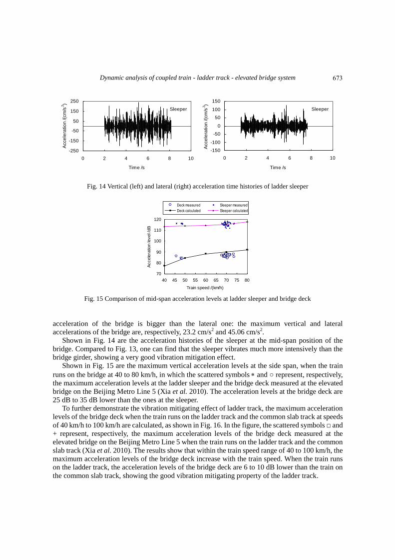
Dynamic analysis of coupled train - ladder track - elevated bridge system
Sleeper
-250
-150
-50
50
150
250
0 2 4 6 8 10
Time s
Acce
lera
tio
n (c
ms
2)
Sleeper
-150
-100
-50
0
50
100
150
0 2 4 6 8 10
Time s
Acce
lera
tio
n (c
ms
2)
Fig 14 Vertical (left) and lateral (right) acceleration time histories of ladder sleeper
70
80
90
100
110
120
40 45 50 55 60 65 70 75 80
Train speed (kmh)
Accele
ratio
n le
vel
dB
Deck measured Sleeper measured
Deck calculated Sleeper calculated
Fig 15 Comparison of mid-span acceleration levels at ladder sleeper and bridge deck
acceleration of the bridge is bigger than the lateral one the maximum vertical and lateral
accelerations of the bridge are respectively 232 cms2 and 4506 cms
2
Shown in Fig 14 are the acceleration histories of the sleeper at the mid-span position of the
bridge Compared to Fig 13 one can find that the sleeper vibrates much more intensively than the
bridge girder showing a very good vibration mitigation effect
Shown in Fig 15 are the maximum vertical acceleration levels at the side span when the train
runs on the bridge at 40 to 80 kmh in which the scattered symbols and represent respectively
the maximum acceleration levels at the ladder sleeper and the bridge deck measured at the elevated
bridge on the Beijing Metro Line 5 (Xia et al 2010) The acceleration levels at the bridge deck are
25 dB to 35 dB lower than the ones at the sleeper
To further demonstrate the vibration mitigating effect of ladder track the maximum acceleration
levels of the bridge deck when the train runs on the ladder track and the common slab track at speeds
of 40 kmh to 100 kmh are calculated as shown in Fig 16 In the figure the scattered symbols and
+ represent respectively the maximum acceleration levels of the bridge deck measured at the
elevated bridge on the Beijing Metro Line 5 when the train runs on the ladder track and the common
slab track (Xia et al 2010) The results show that within the train speed range of 40 to 100 kmh the
maximum acceleration levels of the bridge deck increase with the train speed When the train runs
on the ladder track the acceleration levels of the bridge deck are 6 to 10 dB lower than the train on
the common slab track showing the good vibration mitigating property of the ladder track
673
He Xia Yushu Deng Chaoyi Xia G De Roeck Lin Qi and Lu Sun
70
75
80
85
90
95
100
105
40 50 60 70 80 90 100
Train speed (kmh)
Accele
ratio
n le
vel
dB
Ladder measured
Slab measuredLadder calculated
Slab calculated
Fig 16 Distribution of mid-span acceleration of bridge deck vs train speed
-30
-20
-10
0
10
20
30
0 2 4 6 8 10 12 14 16
Time s
Acce
l (c
ms
2)
-30
-20
-10
0
10
20
30
0 2 4 6 8 10 12 14 16
Time s
Acce
l (c
ms
2)
Fig 17 Time histories of vertical (left) and lateral (right) car-body accelerations
-06
-04
-02
0
02
04
06
0 2 4 6 8 10 12 14 16
Time s
Offlo
ad
fa
cto
r
-06
-04
-02
0
02
04
06
0 2 4 6 8 10 12 14 16
Time s
De
railm
en
t fa
cto
r
Fig 18 Time histories of vehicle off-load factor (left) and derailment factor (right)
As the measurement site was close to the station the train speeds were around 70 kmh on the
ladder track (departing from the station) and 50 kmh on the common slab track (arriving to the
station) Both Figs 15 and 16 show a good accordance between the calculated acceleration levels
and the measured data
422 Responses of train vehicles Shown in Fig 17 are the time histories of the vehicle car-body accelerations when the train runs
on the bridge at a speed of 80 kmh It can be found that the vertical car-body acceleration is slightly
larger than the lateral one and has a higher frequency The maximum accelerations are respectively
2459 cms2
in vertical direction and 1788 cms2 in lateral which are well below the allowable
values related to human comfort
674
Dynamic analysis of coupled train - ladder track - elevated bridge system
0
5
10
15
20
25
30
35
40 50 60 70 80 90 100
Train speed (kmh)
Ca
r-b
od
y a
cce
l (c
ms
2)
Ladder track
Slab track
Fig 19 Distribution of car-body acceleration vs train speed
04
042
044
046
048
40 50 60 70 80 90 100
Train speed (kmh)
Offlo
ad
fa
cto
r
Ladder track
Slab track
035
04
045
05
055
06
065
40 50 60 70 80 90 100
Train speed (kmh)
De
railm
en
t fa
cto
r Ladder track
Slab track
Fig 20 Distribution of off-load factor (left) and derailment factor (right) vs train speed
There are two important evaluation indices considered for the running safety of train vehicles
which are the derailment factor QP (defined as the ratio of the lateral wheel-rail force to the vertical
wheel-rail force) and the offload factor PP (defined as the ratio of the offload vertical wheel-rail
force to the static vertical wheel-rail force) Fig 18 shows the time histories of these two indices of
a vehicle as the train runs on the ladder track of the bridge in which the maximum offload factor is
045 and the maximum derailment factor is 0493
Shown in Figs 19 and 20 are respectively the distributions of the maximum vehicle car-body
accelerations offload factors and derailment factors versus the train speed It should be noticed that
the maximum values are extracted form the corresponding whole histories of the train running
through the bridge at each train speed and normally they do not always appear at the same moment
The results show that within the train speed range of 40 to 100 kmh the dynamic responses of train
vehicles can satisfy the running safety and stability requirements The car-body accelerations and
the offload factors of the vehicle running on the ladder track are smaller than on the slab track and
the derailment factors are very similar to the ones of the slab track
5 Conclusions
A framework for performing dynamic analysis of the coupled train ladder-track and bridge
system has been established and applied to an elevated bridge as a case study The full time histories
675
He Xia Yushu Deng Chaoyi Xia G De Roeck Lin Qi and Lu Sun
of the dynamic responses for the bridge track and train traversing the bridge have been computed
with reasonable computational effort from which the following conclusions can be drawn
bull The analysis model of train-track-bridge system can well simulate the dynamic responses of the
train ladder track and bridge which are verified partly with the field measurement results The
proposed method is able to assess the dynamic behavior of bridges with ladder tracks and the
running vehicles
bull The calculated results and the measured data show that for the bridge with ladder track the
sleeper vibrates much more intensively than the bridge girder the acceleration levels at the deck are
25 dB to 35 dB lower than the ones at the sleeper showing a very good vibration mitigation effect
bull Owing to the elasticity and damping effects of the resilient isolators and the transverse
buffer-pads and the good load dispersion performance of the longitudinal beams the ladder track
can effectively reduce the impact of the train loads on the bridge girder
bull The calculated results show that compared to the common slab track adopting the ladder
sleeper can also reduce the car-body accelerations and offload factors of the vehicle
Acknowledgments
This study is sponsored by the National Key Fundamental Research Program (ldquo973rdquo Program
grant No 2013CB036203) the Natural Science Foundations (U1134206 51308035) the ldquo111rdquo Project
(B13002) and the Fundamental Research Funds for the Central Universities (2013JBM011) of China
and the Flanders (Belgium)-China Bilateral Project (BIL 0707)
References Alves Costa P Calccedilada R and Cardoso A (2012) ldquoBallast mats for the reduction of railway traffic
vibrations Numerical studyrdquo Soil Dyn Earthq Eng 42 137-150
Andersen L Nielsen S and Krenk S (2007) ldquoNumerical methods for analysis of structure and ground
vibration from moving loadsrdquo Comput Struct 85 43-58
Au FTK Lou P Li J Jiang RJ Zhang J Leung CCY Lee PKK Lee JH Wong KY and Chan
HY (2011) ldquoSimulation of vibrations of Ting Kau Bridge due to vehicular loading from measurementsrdquo
Struct Eng Mech 40(4) 471-488
Auersch L (2008) ldquoThe effect of critically moving loads on the vibrations of soft soils and isolated railway
tracksrdquo J Sound Vib 310(3) 587-607
Chen YJ Ju SH Ni SH and Shen YJ (2007) ldquoPrediction methodology for ground vibration induced by
passing trains on bridge structuresrdquo J Sound Vib 302(4-5) 806-820
Clough RW and Penzien J (2003) Dynamics of Structures 2nd Editon Computers amp Structures Inc
Berkeley
Deng YS Xia H Zou YW Qi L and Inoue H (2007) ldquoDynamic action and vibration reduction design
of ladder track on elevated rail transitrdquo Railw Stand Design 51(10) 55-58
Fryacuteba L (1999) Vibration of Solids and Structures under Moving Loads Thomas Telford London
Galviacuten P Romero A and Domiacutenguez J (2010) ldquoVibrations induced by HST passage on ballast and
non-ballast tracksrdquo Soil Dyn Earthq Eng 30(9) 862-873
Guigou-Carter C Villot M Guillerme B and Petit C (2006) ldquoAnalytical and experimental study of
sleeper SAT S 312 in slab track Sateba systemrdquo J Sound Vib 293(3-5) 878-887
Guo WW Xia H and Zhang N (2013) ldquoDynamic responses of Tsing Ma Bridge and running safety of
trains subjected to Typhoon Yorkrdquo Int J Rail Trans 1(32) 181-192
676
Dynamic analysis of coupled train - ladder track - elevated bridge system
He XW Kawatani M and Nishiyama S (2010) ldquoAn analytical approach to train-induced site vibration
around Shinkansen viaductsrdquo Struct Infr Eng 6(6) 689-701
Hui CK and Ng CF (2009) ldquoThe effects of floating slab bending resonances on the vibration isolation of
rail viaductrdquo Applied Acoustics 70(6) 830-844
Hussein MFM and Hunt HEM (2006) ldquoModeling of floating-slab tracks with continuous slabs under
oscillating moving loadsrdquo J Sound Vib 297(1-2) 37-54
Ju SH and Lin HT (2008) ldquoExperimentally investigating finite element accuracy for ground vibrations
induced by high-speed trainsrdquo Eng Struct 30(3) 733-746
Kawatani M Kim CW and Nishitani K (2010) ldquoAssessment of traffic-induced low frequency sound
radiated from a viaduct by field experimentrdquo Interact Multiscale Mech 3(4) 373-388
Lombaert G and Degrande G (2009) ldquoGround-borne vibration due to static and dynamic axle loads of
InterCity and high-speed trainsrdquo J Sound Vib 319(3-5) 1036-1066
Li XZ and Zhu Y (2010) ldquoStochastic space vibration analysis of a train-bridge coupling systemrdquo Interact
Multiscale Mech 3(4) 333-342
Martiacutenez-Rodrigo MD Lavado J and Museros P (2010) ldquoTransverse vibrations in existing railway
bridges under resonant conditions Single-track versus double-track configurationsrdquo Eng Struct 32(7)
1861-1875
Rezvani MA Vesali F and Eghbali A (2013) ldquoDynamic response of railway bridges traversed
simultaneously by opposing moving trainsrdquo Struc Eng Mech 36(5) 713-734
Okuda H Sogabe M and Matsumoto N (2003) ldquoAn environmental performance improvement of railway
structural system using ladder trackrdquo RTRI Rep 17(9) 9-14
Romero A Galviacuten P and Domiacutenguez J (2012) ldquoA time domain analysis of train induced vibrationsrdquo
Earthq Struct 3(3) 297-313
Shih HW Thambiratnam DP and Chan THT (2011) ldquoDamage detection in truss bridges using vibration
based multi-criteria approachrdquo Struc Eng Mech 39(2) 187-206
Takemiya H and Bian XC (2007) ldquoShinkansen high-speed train induced ground vibrations in view of
viaduct-ground interactionrdquo Soil Dyn Earthq Eng 27(6) 506-520
Tahira M and Miyahara K (2003) ldquoInstallation of floating ladder track on bridgesrdquo J Jpn Soc Railw Fac
6 448-450
Tanabe M Wakui H Matsumoto N Okuda H Sogabe M and Komiya S (2003) ldquoComputational model
of a Shinkansen train running on the railway structure and the industrial applicationsrdquo J Mater Proc Tech
140(1-3) 705-710
Wakui H Matsumoto N and Okuda H (2002) ldquoStructure and design of ladder sleeperrdquo New Railw Struct
56(3) 26-28
Wakui H and Matsumoto N (2002) ldquoPerformance test of ballasted ladder track at TTCI and floating ladder
track in Japanrdquo The 18th Transportation Research Board Annual Meeting Washington USA
Wang JF Lin CC and Chen BL (2003) ldquoVibration suppression for high-speed railway bridges using
tuned mass dampersrdquo Int J Solids Struct 40(2) 465-491
Wang SQ Xia H Guo WW and Zhang N (2010) ldquoNonlinear dynamic response analysis of a long-span
suspension bridge under running train and turbulent windrdquo Interact Multiscale Mech 3(4) 309-320
Xia H Cao YM De Roeck G and Degrande G (2007) ldquoEnvironmental problems of vibrations induced by
railway trafficrdquo Front Arch Civ Eng 2 142-152
Xia H Chen JG Xia CY Inoue H Zenda Y and Qi L (2010) ldquoExperimental study of train-induced
structural and environmental vibrations of rail transit elevated bridge with ladder tracksrdquo Proc IMechE
Part F J Rail Rapid Transit 224(304) 115-224
Xia H De Roeck G and Goicolea JM (2011) Bridge vibration and controls New Research Nova Science
Publishers New York
Xin T and Gao L (2011) ldquoReducing slab track vibration into bridge using elastic materials in high speed
railwayrdquo J Sound Vib 330(10) 2237-2248
Yang JR Li JZ and Chen YH (2010) ldquoVibration analysis of CFST tied-arch bridge due to moving
677
He Xia Yushu Deng Chaoyi Xia G De Roeck Lin Qi and Lu Sun
vehiclesrdquo Interact Multiscale Mech 3(4) 389-404
Yang YB and Lin CW (2005) ldquoVehicle-bridge interaction dynamics and potential applicationsrdquo J Sound
Vib 284(1-2) 205-226
Yang YB and Yau JD (2011) ldquoAn iterative interacting method for dynamic analysis of the maglev
train-guideway foundation-soil systemrdquo Eng Struct 33(3) 1013-1024
Yau JD and Fryacuteba L (2007) ldquoResponse of suspended beams due to moving loads and vertical seismic
ground excitationsrdquo Eng Struct 29(12) 3255-3262
Zhai WM Wang SL Zhang N et al (2013a) ldquoHigh-speed trainndashtrackndashbridge dynamic interactions -Part
II experimental validation and engineering applicationrdquo Int J Rail Trans 1(1-2) 25-41
Zhai WM Xia H Cai CB et al (2013b) ldquoHigh-speed trainndashtrackndashbridge dynamic interactions -Part I
theoretical model and numerical simulationrdquo Int J Rail Trans 1(1-2) 3-24
678

He Xia Yushu Deng Chaoyi Xia G De Roeck Lin Qi and Lu Sun
70
75
80
85
90
95
100
105
40 50 60 70 80 90 100
Train speed (kmh)
Accele
ratio
n le
vel
dB
Ladder measured
Slab measuredLadder calculated
Slab calculated
Fig 16 Distribution of mid-span acceleration of bridge deck vs train speed
-30
-20
-10
0
10
20
30
0 2 4 6 8 10 12 14 16
Time s
Acce
l (c
ms
2)
-30
-20
-10
0
10
20
30
0 2 4 6 8 10 12 14 16
Time s
Acce
l (c
ms
2)
Fig 17 Time histories of vertical (left) and lateral (right) car-body accelerations
-06
-04
-02
0
02
04
06
0 2 4 6 8 10 12 14 16
Time s
Offlo
ad
fa
cto
r
-06
-04
-02
0
02
04
06
0 2 4 6 8 10 12 14 16
Time s
De
railm
en
t fa
cto
r
Fig 18 Time histories of vehicle off-load factor (left) and derailment factor (right)
As the measurement site was close to the station the train speeds were around 70 kmh on the
ladder track (departing from the station) and 50 kmh on the common slab track (arriving to the
station) Both Figs 15 and 16 show a good accordance between the calculated acceleration levels
and the measured data
422 Responses of train vehicles Shown in Fig 17 are the time histories of the vehicle car-body accelerations when the train runs
on the bridge at a speed of 80 kmh It can be found that the vertical car-body acceleration is slightly
larger than the lateral one and has a higher frequency The maximum accelerations are respectively
2459 cms2
in vertical direction and 1788 cms2 in lateral which are well below the allowable
values related to human comfort
674
Dynamic analysis of coupled train - ladder track - elevated bridge system
0
5
10
15
20
25
30
35
40 50 60 70 80 90 100
Train speed (kmh)
Ca
r-b
od
y a
cce
l (c
ms
2)
Ladder track
Slab track
Fig 19 Distribution of car-body acceleration vs train speed
04
042
044
046
048
40 50 60 70 80 90 100
Train speed (kmh)
Offlo
ad
fa
cto
r
Ladder track
Slab track
035
04
045
05
055
06
065
40 50 60 70 80 90 100
Train speed (kmh)
De
railm
en
t fa
cto
r Ladder track
Slab track
Fig 20 Distribution of off-load factor (left) and derailment factor (right) vs train speed
There are two important evaluation indices considered for the running safety of train vehicles
which are the derailment factor QP (defined as the ratio of the lateral wheel-rail force to the vertical
wheel-rail force) and the offload factor PP (defined as the ratio of the offload vertical wheel-rail
force to the static vertical wheel-rail force) Fig 18 shows the time histories of these two indices of
a vehicle as the train runs on the ladder track of the bridge in which the maximum offload factor is
045 and the maximum derailment factor is 0493
Shown in Figs 19 and 20 are respectively the distributions of the maximum vehicle car-body
accelerations offload factors and derailment factors versus the train speed It should be noticed that
the maximum values are extracted form the corresponding whole histories of the train running
through the bridge at each train speed and normally they do not always appear at the same moment
The results show that within the train speed range of 40 to 100 kmh the dynamic responses of train
vehicles can satisfy the running safety and stability requirements The car-body accelerations and
the offload factors of the vehicle running on the ladder track are smaller than on the slab track and
the derailment factors are very similar to the ones of the slab track
5 Conclusions
A framework for performing dynamic analysis of the coupled train ladder-track and bridge
system has been established and applied to an elevated bridge as a case study The full time histories
675
He Xia Yushu Deng Chaoyi Xia G De Roeck Lin Qi and Lu Sun
of the dynamic responses for the bridge track and train traversing the bridge have been computed
with reasonable computational effort from which the following conclusions can be drawn
bull The analysis model of train-track-bridge system can well simulate the dynamic responses of the
train ladder track and bridge which are verified partly with the field measurement results The
proposed method is able to assess the dynamic behavior of bridges with ladder tracks and the
running vehicles
bull The calculated results and the measured data show that for the bridge with ladder track the
sleeper vibrates much more intensively than the bridge girder the acceleration levels at the deck are
25 dB to 35 dB lower than the ones at the sleeper showing a very good vibration mitigation effect
bull Owing to the elasticity and damping effects of the resilient isolators and the transverse
buffer-pads and the good load dispersion performance of the longitudinal beams the ladder track
can effectively reduce the impact of the train loads on the bridge girder
bull The calculated results show that compared to the common slab track adopting the ladder
sleeper can also reduce the car-body accelerations and offload factors of the vehicle
Acknowledgments
This study is sponsored by the National Key Fundamental Research Program (ldquo973rdquo Program
grant No 2013CB036203) the Natural Science Foundations (U1134206 51308035) the ldquo111rdquo Project
(B13002) and the Fundamental Research Funds for the Central Universities (2013JBM011) of China
and the Flanders (Belgium)-China Bilateral Project (BIL 0707)
References Alves Costa P Calccedilada R and Cardoso A (2012) ldquoBallast mats for the reduction of railway traffic
vibrations Numerical studyrdquo Soil Dyn Earthq Eng 42 137-150
Andersen L Nielsen S and Krenk S (2007) ldquoNumerical methods for analysis of structure and ground
vibration from moving loadsrdquo Comput Struct 85 43-58
Au FTK Lou P Li J Jiang RJ Zhang J Leung CCY Lee PKK Lee JH Wong KY and Chan
HY (2011) ldquoSimulation of vibrations of Ting Kau Bridge due to vehicular loading from measurementsrdquo
Struct Eng Mech 40(4) 471-488
Auersch L (2008) ldquoThe effect of critically moving loads on the vibrations of soft soils and isolated railway
tracksrdquo J Sound Vib 310(3) 587-607
Chen YJ Ju SH Ni SH and Shen YJ (2007) ldquoPrediction methodology for ground vibration induced by
passing trains on bridge structuresrdquo J Sound Vib 302(4-5) 806-820
Clough RW and Penzien J (2003) Dynamics of Structures 2nd Editon Computers amp Structures Inc
Berkeley
Deng YS Xia H Zou YW Qi L and Inoue H (2007) ldquoDynamic action and vibration reduction design
of ladder track on elevated rail transitrdquo Railw Stand Design 51(10) 55-58
Fryacuteba L (1999) Vibration of Solids and Structures under Moving Loads Thomas Telford London
Galviacuten P Romero A and Domiacutenguez J (2010) ldquoVibrations induced by HST passage on ballast and
non-ballast tracksrdquo Soil Dyn Earthq Eng 30(9) 862-873
Guigou-Carter C Villot M Guillerme B and Petit C (2006) ldquoAnalytical and experimental study of
sleeper SAT S 312 in slab track Sateba systemrdquo J Sound Vib 293(3-5) 878-887
Guo WW Xia H and Zhang N (2013) ldquoDynamic responses of Tsing Ma Bridge and running safety of
trains subjected to Typhoon Yorkrdquo Int J Rail Trans 1(32) 181-192
676
Dynamic analysis of coupled train - ladder track - elevated bridge system
He XW Kawatani M and Nishiyama S (2010) ldquoAn analytical approach to train-induced site vibration
around Shinkansen viaductsrdquo Struct Infr Eng 6(6) 689-701
Hui CK and Ng CF (2009) ldquoThe effects of floating slab bending resonances on the vibration isolation of
rail viaductrdquo Applied Acoustics 70(6) 830-844
Hussein MFM and Hunt HEM (2006) ldquoModeling of floating-slab tracks with continuous slabs under
oscillating moving loadsrdquo J Sound Vib 297(1-2) 37-54
Ju SH and Lin HT (2008) ldquoExperimentally investigating finite element accuracy for ground vibrations
induced by high-speed trainsrdquo Eng Struct 30(3) 733-746
Kawatani M Kim CW and Nishitani K (2010) ldquoAssessment of traffic-induced low frequency sound
radiated from a viaduct by field experimentrdquo Interact Multiscale Mech 3(4) 373-388
Lombaert G and Degrande G (2009) ldquoGround-borne vibration due to static and dynamic axle loads of
InterCity and high-speed trainsrdquo J Sound Vib 319(3-5) 1036-1066
Li XZ and Zhu Y (2010) ldquoStochastic space vibration analysis of a train-bridge coupling systemrdquo Interact
Multiscale Mech 3(4) 333-342
Martiacutenez-Rodrigo MD Lavado J and Museros P (2010) ldquoTransverse vibrations in existing railway
bridges under resonant conditions Single-track versus double-track configurationsrdquo Eng Struct 32(7)
1861-1875
Rezvani MA Vesali F and Eghbali A (2013) ldquoDynamic response of railway bridges traversed
simultaneously by opposing moving trainsrdquo Struc Eng Mech 36(5) 713-734
Okuda H Sogabe M and Matsumoto N (2003) ldquoAn environmental performance improvement of railway
structural system using ladder trackrdquo RTRI Rep 17(9) 9-14
Romero A Galviacuten P and Domiacutenguez J (2012) ldquoA time domain analysis of train induced vibrationsrdquo
Earthq Struct 3(3) 297-313
Shih HW Thambiratnam DP and Chan THT (2011) ldquoDamage detection in truss bridges using vibration
based multi-criteria approachrdquo Struc Eng Mech 39(2) 187-206
Takemiya H and Bian XC (2007) ldquoShinkansen high-speed train induced ground vibrations in view of
viaduct-ground interactionrdquo Soil Dyn Earthq Eng 27(6) 506-520
Tahira M and Miyahara K (2003) ldquoInstallation of floating ladder track on bridgesrdquo J Jpn Soc Railw Fac
6 448-450
Tanabe M Wakui H Matsumoto N Okuda H Sogabe M and Komiya S (2003) ldquoComputational model
of a Shinkansen train running on the railway structure and the industrial applicationsrdquo J Mater Proc Tech
140(1-3) 705-710
Wakui H Matsumoto N and Okuda H (2002) ldquoStructure and design of ladder sleeperrdquo New Railw Struct
56(3) 26-28
Wakui H and Matsumoto N (2002) ldquoPerformance test of ballasted ladder track at TTCI and floating ladder
track in Japanrdquo The 18th Transportation Research Board Annual Meeting Washington USA
Wang JF Lin CC and Chen BL (2003) ldquoVibration suppression for high-speed railway bridges using
tuned mass dampersrdquo Int J Solids Struct 40(2) 465-491
Wang SQ Xia H Guo WW and Zhang N (2010) ldquoNonlinear dynamic response analysis of a long-span
suspension bridge under running train and turbulent windrdquo Interact Multiscale Mech 3(4) 309-320
Xia H Cao YM De Roeck G and Degrande G (2007) ldquoEnvironmental problems of vibrations induced by
railway trafficrdquo Front Arch Civ Eng 2 142-152
Xia H Chen JG Xia CY Inoue H Zenda Y and Qi L (2010) ldquoExperimental study of train-induced
structural and environmental vibrations of rail transit elevated bridge with ladder tracksrdquo Proc IMechE
Part F J Rail Rapid Transit 224(304) 115-224
Xia H De Roeck G and Goicolea JM (2011) Bridge vibration and controls New Research Nova Science
Publishers New York
Xin T and Gao L (2011) ldquoReducing slab track vibration into bridge using elastic materials in high speed
railwayrdquo J Sound Vib 330(10) 2237-2248
Yang JR Li JZ and Chen YH (2010) ldquoVibration analysis of CFST tied-arch bridge due to moving
677
He Xia Yushu Deng Chaoyi Xia G De Roeck Lin Qi and Lu Sun
vehiclesrdquo Interact Multiscale Mech 3(4) 389-404
Yang YB and Lin CW (2005) ldquoVehicle-bridge interaction dynamics and potential applicationsrdquo J Sound
Vib 284(1-2) 205-226
Yang YB and Yau JD (2011) ldquoAn iterative interacting method for dynamic analysis of the maglev
train-guideway foundation-soil systemrdquo Eng Struct 33(3) 1013-1024
Yau JD and Fryacuteba L (2007) ldquoResponse of suspended beams due to moving loads and vertical seismic
ground excitationsrdquo Eng Struct 29(12) 3255-3262
Zhai WM Wang SL Zhang N et al (2013a) ldquoHigh-speed trainndashtrackndashbridge dynamic interactions -Part
II experimental validation and engineering applicationrdquo Int J Rail Trans 1(1-2) 25-41
Zhai WM Xia H Cai CB et al (2013b) ldquoHigh-speed trainndashtrackndashbridge dynamic interactions -Part I
theoretical model and numerical simulationrdquo Int J Rail Trans 1(1-2) 3-24
678

Dynamic analysis of coupled train - ladder track - elevated bridge system
0
5
10
15
20
25
30
35
40 50 60 70 80 90 100
Train speed (kmh)
Ca
r-b
od
y a
cce
l (c
ms
2)
Ladder track
Slab track
Fig 19 Distribution of car-body acceleration vs train speed
04
042
044
046
048
40 50 60 70 80 90 100
Train speed (kmh)
Offlo
ad
fa
cto
r
Ladder track
Slab track
035
04
045
05
055
06
065
40 50 60 70 80 90 100
Train speed (kmh)
De
railm
en
t fa
cto
r Ladder track
Slab track
Fig 20 Distribution of off-load factor (left) and derailment factor (right) vs train speed
There are two important evaluation indices considered for the running safety of train vehicles
which are the derailment factor QP (defined as the ratio of the lateral wheel-rail force to the vertical
wheel-rail force) and the offload factor PP (defined as the ratio of the offload vertical wheel-rail
force to the static vertical wheel-rail force) Fig 18 shows the time histories of these two indices of
a vehicle as the train runs on the ladder track of the bridge in which the maximum offload factor is
045 and the maximum derailment factor is 0493
Shown in Figs 19 and 20 are respectively the distributions of the maximum vehicle car-body
accelerations offload factors and derailment factors versus the train speed It should be noticed that
the maximum values are extracted form the corresponding whole histories of the train running
through the bridge at each train speed and normally they do not always appear at the same moment
The results show that within the train speed range of 40 to 100 kmh the dynamic responses of train
vehicles can satisfy the running safety and stability requirements The car-body accelerations and
the offload factors of the vehicle running on the ladder track are smaller than on the slab track and
the derailment factors are very similar to the ones of the slab track
5 Conclusions
A framework for performing dynamic analysis of the coupled train ladder-track and bridge
system has been established and applied to an elevated bridge as a case study The full time histories
675
He Xia Yushu Deng Chaoyi Xia G De Roeck Lin Qi and Lu Sun
of the dynamic responses for the bridge track and train traversing the bridge have been computed
with reasonable computational effort from which the following conclusions can be drawn
bull The analysis model of train-track-bridge system can well simulate the dynamic responses of the
train ladder track and bridge which are verified partly with the field measurement results The
proposed method is able to assess the dynamic behavior of bridges with ladder tracks and the
running vehicles
bull The calculated results and the measured data show that for the bridge with ladder track the
sleeper vibrates much more intensively than the bridge girder the acceleration levels at the deck are
25 dB to 35 dB lower than the ones at the sleeper showing a very good vibration mitigation effect
bull Owing to the elasticity and damping effects of the resilient isolators and the transverse
buffer-pads and the good load dispersion performance of the longitudinal beams the ladder track
can effectively reduce the impact of the train loads on the bridge girder
bull The calculated results show that compared to the common slab track adopting the ladder
sleeper can also reduce the car-body accelerations and offload factors of the vehicle
Acknowledgments
This study is sponsored by the National Key Fundamental Research Program (ldquo973rdquo Program
grant No 2013CB036203) the Natural Science Foundations (U1134206 51308035) the ldquo111rdquo Project
(B13002) and the Fundamental Research Funds for the Central Universities (2013JBM011) of China
and the Flanders (Belgium)-China Bilateral Project (BIL 0707)
References Alves Costa P Calccedilada R and Cardoso A (2012) ldquoBallast mats for the reduction of railway traffic
vibrations Numerical studyrdquo Soil Dyn Earthq Eng 42 137-150
Andersen L Nielsen S and Krenk S (2007) ldquoNumerical methods for analysis of structure and ground
vibration from moving loadsrdquo Comput Struct 85 43-58
Au FTK Lou P Li J Jiang RJ Zhang J Leung CCY Lee PKK Lee JH Wong KY and Chan
HY (2011) ldquoSimulation of vibrations of Ting Kau Bridge due to vehicular loading from measurementsrdquo
Struct Eng Mech 40(4) 471-488
Auersch L (2008) ldquoThe effect of critically moving loads on the vibrations of soft soils and isolated railway
tracksrdquo J Sound Vib 310(3) 587-607
Chen YJ Ju SH Ni SH and Shen YJ (2007) ldquoPrediction methodology for ground vibration induced by
passing trains on bridge structuresrdquo J Sound Vib 302(4-5) 806-820
Clough RW and Penzien J (2003) Dynamics of Structures 2nd Editon Computers amp Structures Inc
Berkeley
Deng YS Xia H Zou YW Qi L and Inoue H (2007) ldquoDynamic action and vibration reduction design
of ladder track on elevated rail transitrdquo Railw Stand Design 51(10) 55-58
Fryacuteba L (1999) Vibration of Solids and Structures under Moving Loads Thomas Telford London
Galviacuten P Romero A and Domiacutenguez J (2010) ldquoVibrations induced by HST passage on ballast and
non-ballast tracksrdquo Soil Dyn Earthq Eng 30(9) 862-873
Guigou-Carter C Villot M Guillerme B and Petit C (2006) ldquoAnalytical and experimental study of
sleeper SAT S 312 in slab track Sateba systemrdquo J Sound Vib 293(3-5) 878-887
Guo WW Xia H and Zhang N (2013) ldquoDynamic responses of Tsing Ma Bridge and running safety of
trains subjected to Typhoon Yorkrdquo Int J Rail Trans 1(32) 181-192
676
Dynamic analysis of coupled train - ladder track - elevated bridge system
He XW Kawatani M and Nishiyama S (2010) ldquoAn analytical approach to train-induced site vibration
around Shinkansen viaductsrdquo Struct Infr Eng 6(6) 689-701
Hui CK and Ng CF (2009) ldquoThe effects of floating slab bending resonances on the vibration isolation of
rail viaductrdquo Applied Acoustics 70(6) 830-844
Hussein MFM and Hunt HEM (2006) ldquoModeling of floating-slab tracks with continuous slabs under
oscillating moving loadsrdquo J Sound Vib 297(1-2) 37-54
Ju SH and Lin HT (2008) ldquoExperimentally investigating finite element accuracy for ground vibrations
induced by high-speed trainsrdquo Eng Struct 30(3) 733-746
Kawatani M Kim CW and Nishitani K (2010) ldquoAssessment of traffic-induced low frequency sound
radiated from a viaduct by field experimentrdquo Interact Multiscale Mech 3(4) 373-388
Lombaert G and Degrande G (2009) ldquoGround-borne vibration due to static and dynamic axle loads of
InterCity and high-speed trainsrdquo J Sound Vib 319(3-5) 1036-1066
Li XZ and Zhu Y (2010) ldquoStochastic space vibration analysis of a train-bridge coupling systemrdquo Interact
Multiscale Mech 3(4) 333-342
Martiacutenez-Rodrigo MD Lavado J and Museros P (2010) ldquoTransverse vibrations in existing railway
bridges under resonant conditions Single-track versus double-track configurationsrdquo Eng Struct 32(7)
1861-1875
Rezvani MA Vesali F and Eghbali A (2013) ldquoDynamic response of railway bridges traversed
simultaneously by opposing moving trainsrdquo Struc Eng Mech 36(5) 713-734
Okuda H Sogabe M and Matsumoto N (2003) ldquoAn environmental performance improvement of railway
structural system using ladder trackrdquo RTRI Rep 17(9) 9-14
Romero A Galviacuten P and Domiacutenguez J (2012) ldquoA time domain analysis of train induced vibrationsrdquo
Earthq Struct 3(3) 297-313
Shih HW Thambiratnam DP and Chan THT (2011) ldquoDamage detection in truss bridges using vibration
based multi-criteria approachrdquo Struc Eng Mech 39(2) 187-206
Takemiya H and Bian XC (2007) ldquoShinkansen high-speed train induced ground vibrations in view of
viaduct-ground interactionrdquo Soil Dyn Earthq Eng 27(6) 506-520
Tahira M and Miyahara K (2003) ldquoInstallation of floating ladder track on bridgesrdquo J Jpn Soc Railw Fac
6 448-450
Tanabe M Wakui H Matsumoto N Okuda H Sogabe M and Komiya S (2003) ldquoComputational model
of a Shinkansen train running on the railway structure and the industrial applicationsrdquo J Mater Proc Tech
140(1-3) 705-710
Wakui H Matsumoto N and Okuda H (2002) ldquoStructure and design of ladder sleeperrdquo New Railw Struct
56(3) 26-28
Wakui H and Matsumoto N (2002) ldquoPerformance test of ballasted ladder track at TTCI and floating ladder
track in Japanrdquo The 18th Transportation Research Board Annual Meeting Washington USA
Wang JF Lin CC and Chen BL (2003) ldquoVibration suppression for high-speed railway bridges using
tuned mass dampersrdquo Int J Solids Struct 40(2) 465-491
Wang SQ Xia H Guo WW and Zhang N (2010) ldquoNonlinear dynamic response analysis of a long-span
suspension bridge under running train and turbulent windrdquo Interact Multiscale Mech 3(4) 309-320
Xia H Cao YM De Roeck G and Degrande G (2007) ldquoEnvironmental problems of vibrations induced by
railway trafficrdquo Front Arch Civ Eng 2 142-152
Xia H Chen JG Xia CY Inoue H Zenda Y and Qi L (2010) ldquoExperimental study of train-induced
structural and environmental vibrations of rail transit elevated bridge with ladder tracksrdquo Proc IMechE
Part F J Rail Rapid Transit 224(304) 115-224
Xia H De Roeck G and Goicolea JM (2011) Bridge vibration and controls New Research Nova Science
Publishers New York
Xin T and Gao L (2011) ldquoReducing slab track vibration into bridge using elastic materials in high speed
railwayrdquo J Sound Vib 330(10) 2237-2248
Yang JR Li JZ and Chen YH (2010) ldquoVibration analysis of CFST tied-arch bridge due to moving
677
He Xia Yushu Deng Chaoyi Xia G De Roeck Lin Qi and Lu Sun
vehiclesrdquo Interact Multiscale Mech 3(4) 389-404
Yang YB and Lin CW (2005) ldquoVehicle-bridge interaction dynamics and potential applicationsrdquo J Sound
Vib 284(1-2) 205-226
Yang YB and Yau JD (2011) ldquoAn iterative interacting method for dynamic analysis of the maglev
train-guideway foundation-soil systemrdquo Eng Struct 33(3) 1013-1024
Yau JD and Fryacuteba L (2007) ldquoResponse of suspended beams due to moving loads and vertical seismic
ground excitationsrdquo Eng Struct 29(12) 3255-3262
Zhai WM Wang SL Zhang N et al (2013a) ldquoHigh-speed trainndashtrackndashbridge dynamic interactions -Part
II experimental validation and engineering applicationrdquo Int J Rail Trans 1(1-2) 25-41
Zhai WM Xia H Cai CB et al (2013b) ldquoHigh-speed trainndashtrackndashbridge dynamic interactions -Part I
theoretical model and numerical simulationrdquo Int J Rail Trans 1(1-2) 3-24
678

He Xia Yushu Deng Chaoyi Xia G De Roeck Lin Qi and Lu Sun
of the dynamic responses for the bridge track and train traversing the bridge have been computed
with reasonable computational effort from which the following conclusions can be drawn
bull The analysis model of train-track-bridge system can well simulate the dynamic responses of the
train ladder track and bridge which are verified partly with the field measurement results The
proposed method is able to assess the dynamic behavior of bridges with ladder tracks and the
running vehicles
bull The calculated results and the measured data show that for the bridge with ladder track the
sleeper vibrates much more intensively than the bridge girder the acceleration levels at the deck are
25 dB to 35 dB lower than the ones at the sleeper showing a very good vibration mitigation effect
bull Owing to the elasticity and damping effects of the resilient isolators and the transverse
buffer-pads and the good load dispersion performance of the longitudinal beams the ladder track
can effectively reduce the impact of the train loads on the bridge girder
bull The calculated results show that compared to the common slab track adopting the ladder
sleeper can also reduce the car-body accelerations and offload factors of the vehicle
Acknowledgments
This study is sponsored by the National Key Fundamental Research Program (ldquo973rdquo Program
grant No 2013CB036203) the Natural Science Foundations (U1134206 51308035) the ldquo111rdquo Project
(B13002) and the Fundamental Research Funds for the Central Universities (2013JBM011) of China
and the Flanders (Belgium)-China Bilateral Project (BIL 0707)
References Alves Costa P Calccedilada R and Cardoso A (2012) ldquoBallast mats for the reduction of railway traffic
vibrations Numerical studyrdquo Soil Dyn Earthq Eng 42 137-150
Andersen L Nielsen S and Krenk S (2007) ldquoNumerical methods for analysis of structure and ground
vibration from moving loadsrdquo Comput Struct 85 43-58
Au FTK Lou P Li J Jiang RJ Zhang J Leung CCY Lee PKK Lee JH Wong KY and Chan
HY (2011) ldquoSimulation of vibrations of Ting Kau Bridge due to vehicular loading from measurementsrdquo
Struct Eng Mech 40(4) 471-488
Auersch L (2008) ldquoThe effect of critically moving loads on the vibrations of soft soils and isolated railway
tracksrdquo J Sound Vib 310(3) 587-607
Chen YJ Ju SH Ni SH and Shen YJ (2007) ldquoPrediction methodology for ground vibration induced by
passing trains on bridge structuresrdquo J Sound Vib 302(4-5) 806-820
Clough RW and Penzien J (2003) Dynamics of Structures 2nd Editon Computers amp Structures Inc
Berkeley
Deng YS Xia H Zou YW Qi L and Inoue H (2007) ldquoDynamic action and vibration reduction design
of ladder track on elevated rail transitrdquo Railw Stand Design 51(10) 55-58
Fryacuteba L (1999) Vibration of Solids and Structures under Moving Loads Thomas Telford London
Galviacuten P Romero A and Domiacutenguez J (2010) ldquoVibrations induced by HST passage on ballast and
non-ballast tracksrdquo Soil Dyn Earthq Eng 30(9) 862-873
Guigou-Carter C Villot M Guillerme B and Petit C (2006) ldquoAnalytical and experimental study of
sleeper SAT S 312 in slab track Sateba systemrdquo J Sound Vib 293(3-5) 878-887
Guo WW Xia H and Zhang N (2013) ldquoDynamic responses of Tsing Ma Bridge and running safety of
trains subjected to Typhoon Yorkrdquo Int J Rail Trans 1(32) 181-192
676
Dynamic analysis of coupled train - ladder track - elevated bridge system
He XW Kawatani M and Nishiyama S (2010) ldquoAn analytical approach to train-induced site vibration
around Shinkansen viaductsrdquo Struct Infr Eng 6(6) 689-701
Hui CK and Ng CF (2009) ldquoThe effects of floating slab bending resonances on the vibration isolation of
rail viaductrdquo Applied Acoustics 70(6) 830-844
Hussein MFM and Hunt HEM (2006) ldquoModeling of floating-slab tracks with continuous slabs under
oscillating moving loadsrdquo J Sound Vib 297(1-2) 37-54
Ju SH and Lin HT (2008) ldquoExperimentally investigating finite element accuracy for ground vibrations
induced by high-speed trainsrdquo Eng Struct 30(3) 733-746
Kawatani M Kim CW and Nishitani K (2010) ldquoAssessment of traffic-induced low frequency sound
radiated from a viaduct by field experimentrdquo Interact Multiscale Mech 3(4) 373-388
Lombaert G and Degrande G (2009) ldquoGround-borne vibration due to static and dynamic axle loads of
InterCity and high-speed trainsrdquo J Sound Vib 319(3-5) 1036-1066
Li XZ and Zhu Y (2010) ldquoStochastic space vibration analysis of a train-bridge coupling systemrdquo Interact
Multiscale Mech 3(4) 333-342
Martiacutenez-Rodrigo MD Lavado J and Museros P (2010) ldquoTransverse vibrations in existing railway
bridges under resonant conditions Single-track versus double-track configurationsrdquo Eng Struct 32(7)
1861-1875
Rezvani MA Vesali F and Eghbali A (2013) ldquoDynamic response of railway bridges traversed
simultaneously by opposing moving trainsrdquo Struc Eng Mech 36(5) 713-734
Okuda H Sogabe M and Matsumoto N (2003) ldquoAn environmental performance improvement of railway
structural system using ladder trackrdquo RTRI Rep 17(9) 9-14
Romero A Galviacuten P and Domiacutenguez J (2012) ldquoA time domain analysis of train induced vibrationsrdquo
Earthq Struct 3(3) 297-313
Shih HW Thambiratnam DP and Chan THT (2011) ldquoDamage detection in truss bridges using vibration
based multi-criteria approachrdquo Struc Eng Mech 39(2) 187-206
Takemiya H and Bian XC (2007) ldquoShinkansen high-speed train induced ground vibrations in view of
viaduct-ground interactionrdquo Soil Dyn Earthq Eng 27(6) 506-520
Tahira M and Miyahara K (2003) ldquoInstallation of floating ladder track on bridgesrdquo J Jpn Soc Railw Fac
6 448-450
Tanabe M Wakui H Matsumoto N Okuda H Sogabe M and Komiya S (2003) ldquoComputational model
of a Shinkansen train running on the railway structure and the industrial applicationsrdquo J Mater Proc Tech
140(1-3) 705-710
Wakui H Matsumoto N and Okuda H (2002) ldquoStructure and design of ladder sleeperrdquo New Railw Struct
56(3) 26-28
Wakui H and Matsumoto N (2002) ldquoPerformance test of ballasted ladder track at TTCI and floating ladder
track in Japanrdquo The 18th Transportation Research Board Annual Meeting Washington USA
Wang JF Lin CC and Chen BL (2003) ldquoVibration suppression for high-speed railway bridges using
tuned mass dampersrdquo Int J Solids Struct 40(2) 465-491
Wang SQ Xia H Guo WW and Zhang N (2010) ldquoNonlinear dynamic response analysis of a long-span
suspension bridge under running train and turbulent windrdquo Interact Multiscale Mech 3(4) 309-320
Xia H Cao YM De Roeck G and Degrande G (2007) ldquoEnvironmental problems of vibrations induced by
railway trafficrdquo Front Arch Civ Eng 2 142-152
Xia H Chen JG Xia CY Inoue H Zenda Y and Qi L (2010) ldquoExperimental study of train-induced
structural and environmental vibrations of rail transit elevated bridge with ladder tracksrdquo Proc IMechE
Part F J Rail Rapid Transit 224(304) 115-224
Xia H De Roeck G and Goicolea JM (2011) Bridge vibration and controls New Research Nova Science
Publishers New York
Xin T and Gao L (2011) ldquoReducing slab track vibration into bridge using elastic materials in high speed
railwayrdquo J Sound Vib 330(10) 2237-2248
Yang JR Li JZ and Chen YH (2010) ldquoVibration analysis of CFST tied-arch bridge due to moving
677
He Xia Yushu Deng Chaoyi Xia G De Roeck Lin Qi and Lu Sun
vehiclesrdquo Interact Multiscale Mech 3(4) 389-404
Yang YB and Lin CW (2005) ldquoVehicle-bridge interaction dynamics and potential applicationsrdquo J Sound
Vib 284(1-2) 205-226
Yang YB and Yau JD (2011) ldquoAn iterative interacting method for dynamic analysis of the maglev
train-guideway foundation-soil systemrdquo Eng Struct 33(3) 1013-1024
Yau JD and Fryacuteba L (2007) ldquoResponse of suspended beams due to moving loads and vertical seismic
ground excitationsrdquo Eng Struct 29(12) 3255-3262
Zhai WM Wang SL Zhang N et al (2013a) ldquoHigh-speed trainndashtrackndashbridge dynamic interactions -Part
II experimental validation and engineering applicationrdquo Int J Rail Trans 1(1-2) 25-41
Zhai WM Xia H Cai CB et al (2013b) ldquoHigh-speed trainndashtrackndashbridge dynamic interactions -Part I
theoretical model and numerical simulationrdquo Int J Rail Trans 1(1-2) 3-24
678


![Untitled-1 [cdn.kitsune.tools] · Industrial Ladder Scaffold FRP Stool Ladder Aluminum Ladder Aluminium Tiltable Step FRP Wall Supporting Aluminum Wall Supporting Tanker Ladder —self](https://static.fdocuments.in/doc/165x107/5f0ebf297e708231d440bd69/untitled-1-cdn-industrial-ladder-scaffold-frp-stool-ladder-aluminum-ladder-aluminium.jpg)