dynafor - Lifting Gear Hire of the system, ... - an IBM PC microprocessor, or ... Upon releasing the...
22
equipment in accordance with CE directives ® ® dynafor ® LCD load indicating devices LLX range MAX. 12.5 t dynafor t A 0000 0398054 - 01/97 operating and maintenance instructions
-
Upload
truongthuy -
Category
Documents
-
view
216 -
download
2
Transcript of dynafor - Lifting Gear Hire of the system, ... - an IBM PC microprocessor, or ... Upon releasing the...

equipment inaccordance withCE directives
® ®
dynafor®
LCD load indicating devicesLLX range
MAX. 12.5 t
dynafor
t
A 0000
0398054 - 01/97
operatingandmaintenanceinstructions
®
®
2
CONTENTS
General warning .................................................................................... 3
1- Presentation ................................................................................ 41-1 Operating principle ..................................................................... 41-2 Description and marking ............................................................ 51-3 Accessories ................................................................................ 51-3.1 Anchor shackles ......................................................................... 61-3.2 Hooks .......................................................................................... 7
2- Technical data ............................................................................. 82-1 Specification and dimensions .................................................... 82-2 Functions..................................................................................... 92-2.1 Operating instructions ................................................................ 92-2.2 Configuration .............................................................................. 92-2.3 Other functions ........................................................................... 122-2.4 Stop ............................................................................................. 132-3 Storage and transport ................................................................. 13
3- Safety .......................................................................................... 143-1 Overload ..................................................................................... 143-2 Low battery condition ................................................................. 14
4- Operating precautions ................................................................ 14
5- Other equipment and functions .................................................. 165-1 Hand held display ....................................................................... 165-2 Wall mounted display ................................................................. 175-3 Data console ............................................................................... 185-4 PC card ....................................................................................... 195-5 Portable interface for DYNAFOR® LLX (RS232) .......................... 195-6 Portable printer ........................................................................... 205-7 Mains power adapter .................................................................. 21
6- Maintenance ............................................................................... 21
7- Statutory controls ........................................................................ 21
8- Troubleshooting .......................................................................... 22

®
®
3
GENERAL WARNING
1 - Before using the DYNAFOR ® LLX, it is essential for the safe and correctoperation of the equipment that this manual be read and fully understood andthat all the instructions be followed. This manual should be made available toevery operator. Extra copies of this manual will be supplied on request.
2 - Le DYNAFOR® LLX units are used in lifting applications which require completesafety of operation. Therefore, ensure that this unit is only handed over foruse or rigging to an operator who is trained to operate it in a safe andresponsible manner.
3 - Never apply to the DYNAFOR ® LLX a load or effort greater than the workingload limit and never use it for an application for which it is not intended. Neverapply twisting or flexing efforts to the DYNAFOR ® LLX. Apply only tractionefforts.
4 - Ensure that your equipment is not subjected to knocks, particulary to the frontdisplay and the side areas.
5 - Ensure that your equipment is not handed to any unauthorised persons. Neveruse a unit that is not in apparently good condition.
6 - TRACTEL S.A. declines any responsability for the consequences of dismantlingor altering the unit by any unauthorised person.
7 - DYNAFOR® LLX units must not be used in explosive atmospheres.
8 - DYNAFOR® must not be used in systems for lifting people without havingpreviously checked the compatibility of the operating coefficients and havingcompleted an analysis of the specific risks. Appropriate measures should betaken to eliminate the risks.
9 - Any operation of the DYNAFOR ® LLX with complementary equipment relayingthe signals to another operating system should be preceded by the user or theassembler of the system, of an analysis of the specific risks of the operatingfunctions. Appropriate measures should be taken to eliminate the risks.

®
®
4
1- PRESENTATION
1-1 Operating principle
The DYNAFOR® LLX range of load indicating devices are highly accurate instruments formeasuring tensile forces and suitable for a wide variety of applications where an instant indicationof the load applied is required.
The principle of the DYNAFOR® is the movement of a material within its elastic limit, usingbonded strain gauges to give a signal, relative to the load applied. The unit will operate in anyposition.
The DYNAFOR® LLX range uses microprocessor based electronics to process the signal to givean accurate and immediate read-out, on the LCD, of the load applied.
The range of DYNAFOR® LLX load indicators comprises models from 250 kg to 250 t.
The DYNAFOR® LLX unit is supplied complete with a set of Alkaline long life batteries, within acarrying case, together with an operating manual, 2 calibration certificates and a CE declarationof conformity.
Fig. A
MAX. 12.5 t
dynafor
t
A 0000

®
®
5
1-2 Description and marking
Set up of the various functions and operation of the DYNAFOR® LLX are all possible by use of asequence of operations of the 3 push-button controls on the front of the unit.
The DYNAFOR® LLX load indicator is supplied by 3 x 1.5 Volt, AA or R6 type, batteries whichhave an operating life up to 250 hours when the unit is set to update the display every second(configuration C2-2). The batteries should be in the correct position indicated at the backs ofthe battery pocket.
When the batteries become low, there is an indication for "low battery condition" on the display.
+ –
When the low battery condition is shown, the batteries should be replaced immediately althoughthe unit will continue to operate correctly until the units is switched off.If the batteries are exhausted, the unit will fail to start up again when the ON/OFF button ispressed.
N.B. : Look after your DYNAFOR LLX. Use only sealed, leak-proof batteries.
A BNC socket allows the user, depending on the requirment, to connect the DYNAFOR® LLXto :
- a portable remote display- a wall-mounted display- a data console- an IBM PC microprocessor, or equivalent- a printer- a transformer power supplyAll the above equipment is described in this manual.
A label attached to the side of the machine sets out :- the main advice- the operating instructions- the use of the push-buttons- CE marking.
1-3 Accessories
to install the DYNAFOR® LLX within a lifting or a pulling system, use anchor shackles and/orswivel hooks which have been specially selected for use with DYNAFOR® LLX units and detailedin our catalogue.
If you need to use the machine in a specific arrangement, the best results of the DYNAFOR®
LLX are obtained with anchor pins of the same diameter as the recommended anchor shackles.
operating instructions1. DYNAFOR must be of comparable
load to be applied.
2. ON/OFF button
3. Unit of measurement appears onthe display.
4. Attach DYNAFOR to lifting orpulling arrangement. Re-zero ifnecessary by pressing the tarebutton.
"TARE" shows on display.
5. Press for peak hold."MAX" shows on display.
6. After use, ensure DYNAFOR isswitched off by pressing ON/OFF.
"STOP" display for severalseconds and LCD goesblank.
7. For full details and operating advice,please refer to instruction manual.

®
®
6
1-3. 1 ANCHOR SHACKLES
U.S. Federal Specification (RR - C.271 b type IV classe 1)
Safety factor : 6 up to 55 t
Testing load : 2 x s.w.l. and according to I.L.O.
Working load limit permanently shown on every shackle
Finish : painted or galvanised
Pins : Alloy steel
DYNAFOR® W.L.L. A B C D Ø WeightModels Tonne mm mm mm mm mm kg
LLX-0,25/0.5et 1.25 1,5 11 13 18 43 29 0,2
LLX-2.5 3,25 16 20 27 60 42 0,6
LLX-5 6,5 22 25 37 84 58 1,4
LLX-12.5 13,5 35 38 57 132 89 4,4
LLX-25 25 44 50 73 178 110 14
LLX-50 50 64 70 105 267 150 39,7
LLX-100 100 89 95 146 381 241 97
LLX-250 250 125 140 200 540 320 340

®
®
7
1-3. 2 HOOKS
SWIVEL HOOK FOR DYNAFOR ® LLX 12.5 t
Swivel hook for A B C D E F G H Weight DYNAFOR® models kg
LLX-0.25/0.5 121 22 21 16 25 33 60 30 0.71
LLX-1.25 151 24 17 16 29 37.5 80 44 1.5
LLX-2.5 175 32 27 20 30 45 90 44 2.8
LLX-5 240 61 34 24.5 40 53 130 53 4.5
LLX-12.5 342 80 60 45 57 75 16
SWIVEL HOOK FOR DYNAFOR ® LLX 0.250 t to 5 t

®
®
8
2- TECHNICAL DATA
2-1 Specification and dimensions
B
G
C
I
H
A E
F
D
Model LLX-0.25 LLX-0.5 LLX-1.25 LLX-2.5 LLX-5 LLX-12.5 LLX-25 LLX-50 LLX-100 LLX-250
Capacity t 0.25 0.50 1.25 2.5 5 12.5 25 50 100 250
Accuracy ±kg 0.5 1 2.5 5 10 25 50 100 200 500
Smallest load increment kg 0.1 0,2 0.5 1 2 5 10 20 50 100
Test load t 0.5 1 2.5 5 10 25 50 85 145 333
Max. display kg/t 250.0 500.0 1250.0 2500 5000 12500 25000 50000 100.00 250.0
Height of digits mm 18 18 18 18 18 25 25 25 25 44
Weight kg 1.1 1.1 1.1 1.4 1.9 3.8 6.6 15.1 46 215
Material Alluminium alloy
Dimensions mm A 190 190 190 214 226 310 360 440 660 905
B 83 83 83 83 90 110 134 164 260 424
C 56 56 56 56 56 58 68 98 118 248
D 16 16 16 24 32 47 56 72 108 150
E 166 166 166 184 197 243 272 332 488 685
F 12 12 12 15 14.5 33.5 44 54 86 110
G 47 47 47 47 54 70 84 104 174 250
H 43 43 43 50 58 92 114 142 227 310
I 16 16 16 25 32 48 58 86 104 190

®
®
9
2-2 Functions
2- 2. 1 Operating instructions
Press the ON/OFF button (T1) :
The unit will automatically go through a set up check procedure to ensure that the electronicsare operating correctly.
During this time all the display will be lit up :kN daN lbs ton kg
STOP MAX TARE+ –
When this procedure is completed, the DYNAFOR® LLX will display :
- the version of the software :
- The last calibration date (month year) :
- Then , the zero will be displayed, depending kg
If, on switching ON, the DYNAFOR® LLX is subjected to a load greater than 10% of its workingload limit, the unit will display the value of the load using the last used zero as a reference point.If the load is less than 10%, the unit will display zero.
The unit will adopt the configuration of the various functions that were last used (i.e. the unit ofmeasurement, the response rate, and the auto-shut down, On or Off). If the configuration is asrequired proceed to section 3, otherwise continue reading Section 2 to alter the configuration.
2- 2. 2 Configuration
How to modify / check the configuration of the DYNAFOR® LLX :
All modification programmes within the configuration of the unit are established by using asequence of operations of the 3-push buttons on the front of the unit. These are reffered to asT1. T2. or T3. To activate the modification programmes, press buttons T1 and T3 simultaneously.
T1 (ON/OFF) and T3 (PEAK HOLD)
the display will show :
Upon releasing the two buttons T1 and T3 the display will show the first function to be modified :
kg

®
®
10
The unit is designed to go through a series of functions in the modification programme andthese will appear on the display in the following order :
Unit of measurement - Prog. C1Response rate - Prog. C2Automatic shutdown - Prog. C3Use of output - Prog. C4
Adress of DYNAFOR® LLX units - Prog. C5 (only if C4-2 is selected)
If using a number of DYNAFOR® LLX units connected to a single PC it is necessary to carry outthe full series of modification programmes for each individual unit.
a - Unit of measurement "Programme C1" :The display will show "C1" followed by a digit 1 to 6 depending on the information currently inthe memory. The following shows the possible units of measurement within the "C1" programmeat seen on the display.
C1 - 1 = kg (kilogramme)C1 - 2 = t (tonne)C1 - 3 = ton (short ton = 2.000 Ibs)C1 - 4 = lbs (pounds)C1 - 5 = daN (decanewton)
C1 - 6 = kN (kilonewton)
Press button T3 to select the unit of measurement in numerical order :1 - 2 - 3 - 4 - 5 - 6
Press button T2 to select the unit of measurement in reverse numerical order :6 - 5 - 4 - 3 - 2 - 1
When you have reached the selected unit of measurement press button T1.On pressing button T1 the selection is confirmed, entered in the memory and the display willautomatically pass to the next function.To modify only the unit of measurement, press button T1 several times until the display returns tonormal.
b - Response rate of display "programme C2"The response rate of the display is variable to allow the operator to economise the powerconsumption and to suit the particular application. The response rate ranges from continuousupdating of the display (appropriate in testing arrangements and the use of peak hold facility,although using more battery power) to updating of the display every eight seconds for applicationswhere only an indication or general monitoring of the load applied is required (whilst reducingthe power consumption to a minimum to prolong the battery life).The display will show "C2" followed by a digit 0-5 depending on the information currently in thememory. The following shows the possible variations within the "C2" programme as seen on thedisplay : C2 - 0 = display updated every quarter second
C2 - 1 = display updated every half second
C2 - 2 = display updated every second
C2 - 3 = display updated every two second
C2 - 4 = display updated every four second
C2 - 5 = display updated every eight seconds

®
®
11
Press button T3 to select the response rate in numerical order :
0 - 1 - 2 - 3 - 4 - 5
Press button T2 to select the response rate in reverse numerical order :
5 - 4 - 3 - 2 - 1 - 0
IMPORTANT : The response rate has a direct influence on the battery life. Choose theresponse rate appropriate to your application.
When you have the selected response rate, press button T1.On pressing T1, the selection is confirmed, entered in the memory and the display willautomatically pass to the next function.
c -Automatic shutdown "Programme C3"
The display will show "C3" followed by 0 or 1 depending on wether function of automaticshutdown is ON or OFF.
Press the button T2 to turn OFF the automatic shutdown. The display will show :
The unit will operate continuously until is switched off or the batteries are exhausted.Press the button T3 to turn ON the automatic shutdown. The display will show :
STOP
The unit will switch itself off after 20 minutes without T2 or T3 button being operated, or anysignificant change in the load applied.
When you have selected the Automatic shutdown ON or OFF, press the button T1. On pressingT1 the selection is confirmed, entered in the memory and the display will automatically pass tothe next function.
d - Use of output "programme C4" :
It is necessary to indicate to the microprocessor in the DYNAFOR® LLX the use of the BNCoutput socket. The display will show "C4" followed by 0,1 or 2 depending on the informationcurrently in the memory.
C4 - 0 = Unit is operating on its own and is not connected to another device or
remote read-out through BNC output socket.
C4 - 1 = Unit is connected to a remote read-out through BNC socket.
C4 - 2 = Unit is connected to a PC through BNC socket.
Press button T3 to select the use of the output in numerical order : 0 - 1 - 2
Press button T2 to select the use of the output in reverse numerical order : 2 - 1 - 0
When you have reached the selected output, press the button T1. On pressing T1 selection isconfirmed, entered in the memory and the display will automatically pass to the next function.
®
®
12
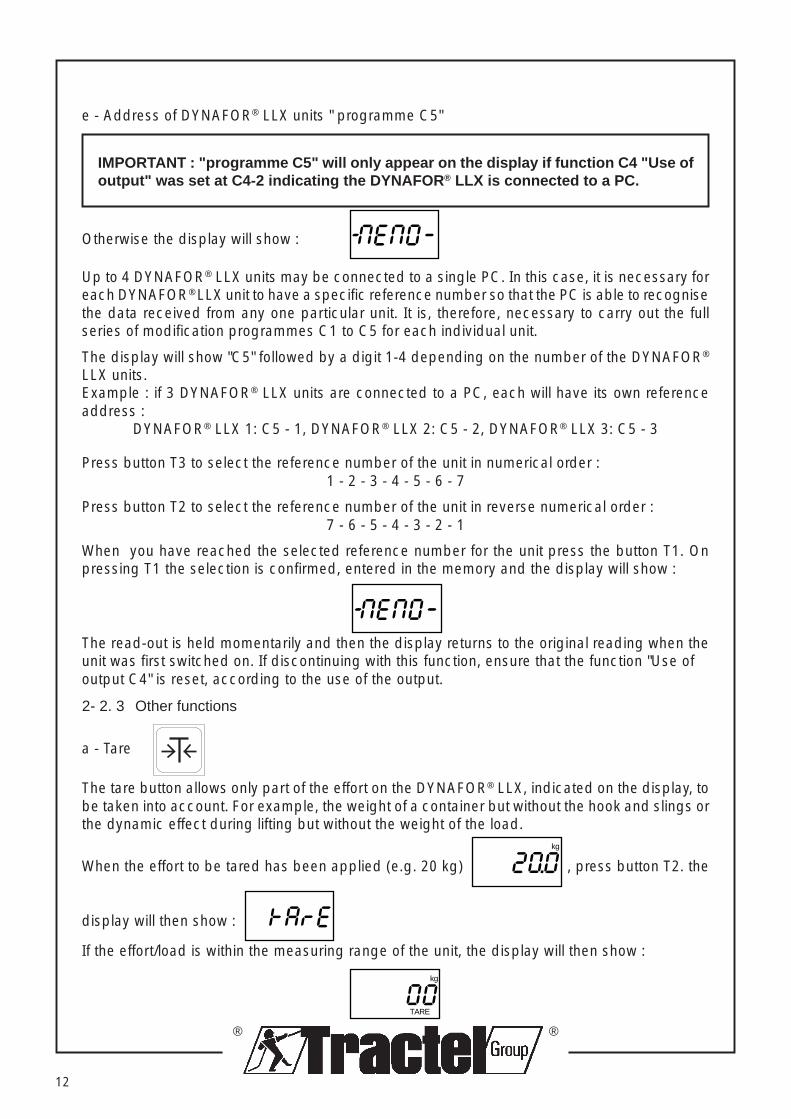
e - Address of DYNAFOR® LLX units " programme C5"
IMPORTANT : "programme C5" will only appear on the display if function C4 "Use ofoutput" was set at C4-2 indicating the DYNAFOR ® LLX is connected to a PC.
Otherwise the display will show :
Up to 4 DYNAFOR® LLX units may be connected to a single PC. In this case, it is necessary foreach DYNAFOR® LLX unit to have a specific reference number so that the PC is able to recognisethe data received from any one particular unit. It is, therefore, necessary to carry out the fullseries of modification programmes C1 to C5 for each individual unit.
The display will show "C5" followed by a digit 1-4 depending on the number of the DYNAFOR®
LLX units.Example : if 3 DYNAFOR® LLX units are connected to a PC, each will have its own referenceaddress :
DYNAFOR® LLX 1: C5 - 1, DYNAFOR® LLX 2: C5 - 2, DYNAFOR® LLX 3: C5 - 3
Press button T3 to select the reference number of the unit in numerical order :1 - 2 - 3 - 4 - 5 - 6 - 7
Press button T2 to select the reference number of the unit in reverse numerical order :7 - 6 - 5 - 4 - 3 - 2 - 1
When you have reached the selected reference number for the unit press the button T1. Onpressing T1 the selection is confirmed, entered in the memory and the display will show :
The read-out is held momentarily and then the display returns to the original reading when theunit was first switched on. If discontinuing with this function, ensure that the function "Use ofoutput C4" is reset, according to the use of the output.
2- 2. 3 Other functions
a - Tare
The tare button allows only part of the effort on the DYNAFOR® LLX, indicated on the display, tobe taken into account. For example, the weight of a container but without the hook and slings orthe dynamic effect during lifting but without the weight of the load.
When the effort to be tared has been applied (e.g. 20 kg) kg
, press button T2. the
display will then show :
If the effort/load is within the measuring range of the unit, the display will then show :
kg
TARE

®
®
13
If the DYNAFOR® LLX is loaded to a value of 40.8 kg, lightly press button T2 to transfer from thenett value (40.8 kg) :
kg
TARE
to the gross value (Tare of 20 kg + nett load 40,8 kg) of :
kg
b - Peak hold
This function holds on the display the maximum load applied (e.g. in a break test or a dynamicload which is reached momentarily and may not be seen).
With the unit switched on, press the peak Hold button (T3). MAX appears on the lower portion ofthe display :
kg
MAX
Press the Peak Hold button (T3) a second time to return the display to the current load applied,if any.
N.B. : The Peak Hold button function automatically over-rides the response rate (programmeC2 of the unit configuration) held in the memory so that there is virtually continuousmonitoring of the load. The display is updated 40 times per second.
2- 2. 4 Stop
To switch off the unit, press T1 button.
The display will show : for a few seconds and then gp blank.
2- 3 Storage/transport
When the DYNAFOR® LLX is not in use, it is recommanded that the unit should be stored in itspacking case for storage and/or transport.
Should the unit be not used for a prolonged period, it is advisable to remove the batteries.
®
®
14
3- SAFETY
The DYNAFOR® LLX is designed to operate within an ambient temperature range of -10°C to+40°C. For operation at temperature greater than +40°C, the unit should be protected by athermal screen or cooling cover.
3- 1 Overload
When the load applied exceeds the capacity of the unit (e.g. : LLX-12.5 t loaded to 14 t), theoverload condition is displayed :
On reducing the load below the capacity of the unit the display will show the current loadapplied.
Providing the overload has not exceeded twice the capacity of the unit, there should be nodamage to the unit or its electronics. Under normal operating conditions, the unit should continueoperate correctly.
It should be noted that when using the TARE function, the overload function will still operatewhere the real/effective capacity is exceeded, to prevent damage to the unit and/or the lifting/test arrangement.
3- 2 Low battery condition
When the batteries become low, there is an indication for "low battery condition" on the lowerpart of the display :
When the low battery condition is shown, the batteries should be replaced immediately, althoughthe unit will continue to operate correctly until the unit is switched off. If the batteries are exhausted,the unit will fail to start up again when the ON/OFF button is pressed.
N.B. : To look after your unit, only use sealed leak-proof batteries.
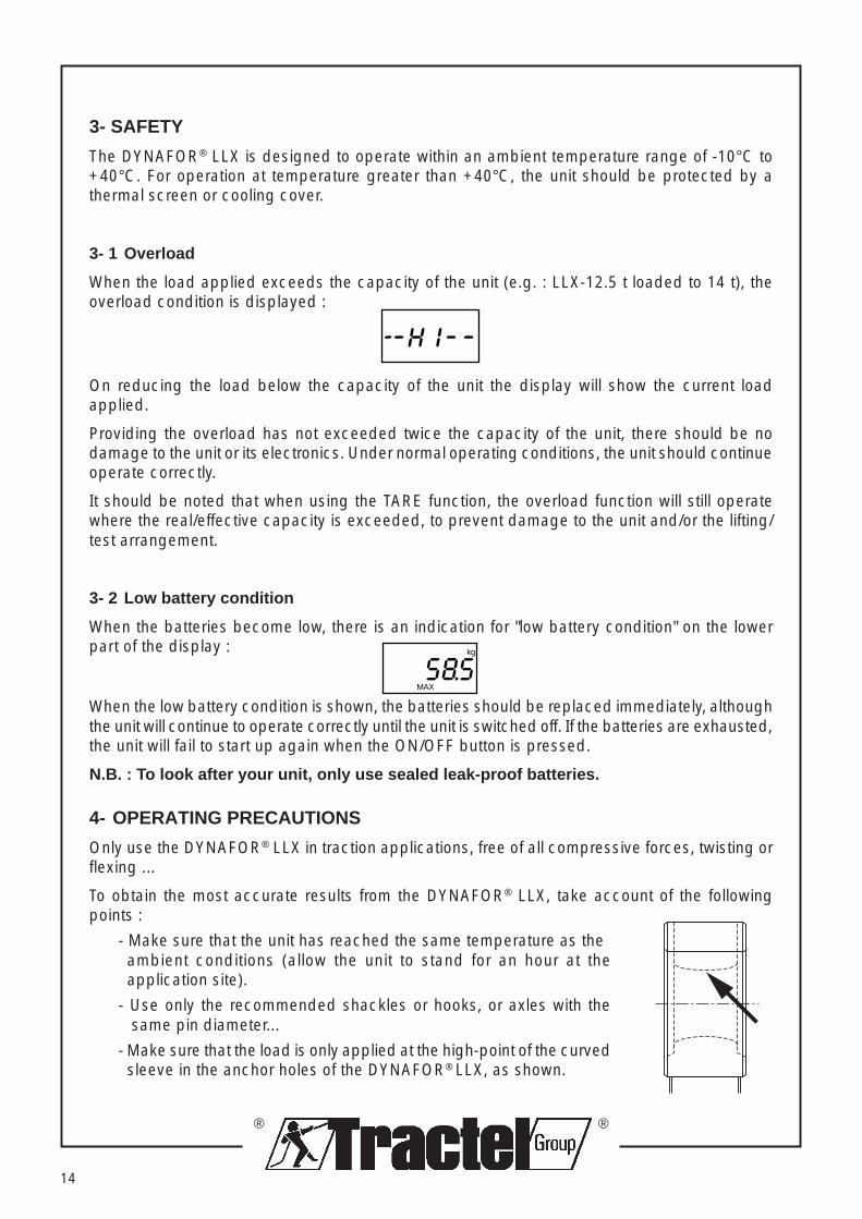
4- OPERATING PRECAUTIONS
Only use the DYNAFOR® LLX in traction applications, free of all compressive forces, twisting orflexing ...
To obtain the most accurate results from the DYNAFOR® LLX, take account of the followingpoints :
- Make sure that the unit has reached the same temperature as theambient conditions (allow the unit to stand for an hour at theapplication site).
- Use only the recommended shackles or hooks, or axles with the same pin diameter...
- Make sure that the load is only applied at the high-point of the curvedsleeve in the anchor holes of the DYNAFOR® LLX, as shown.
kg
MAX

®
®
Forbidden operations
It is forbidden to use the DYNAFOR ® LLX with a system for lifting persons unlesspreviously having carried out a specific risk analysis.
Never modify the DYNAFOR ® LLX by machining, drilling or other method.
Neveruse the DYNAFOR ® LLX beyond its maximum capacity.
Never use arc welding equipment with the DYNAFOR ® LLX fitted within the earthingcircuit.
15
- To apply only traction forces :- Centre the unit between the shackles, not allowing it to rub on the side sections.- Always check the appropriate stength of anchor points and connections.
- Connect the loads on the lifting machines using shackles, hooks or axles previously describedin this manual and designed for use with DYNAFOR® LLX.
Incorrect operationCorrect operation
®
®
16
5- OTHER EQUIPMENT AND FUNCTIONS
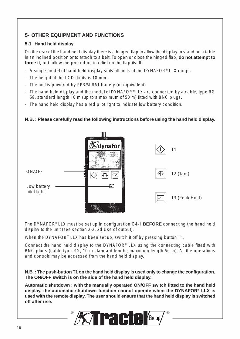
5-1 Hand held display
On the rear of the hand held display there is a hinged flap to allow the display to stand on a tablein an inclined position or to attach to a belt. To open or close the hinged flap, do not attempt toforce it , but follow the procedure in relief on the flap itself.
- A single model of hand held display suits all units of the DYNAFOR® LLX range.
- The height of the LCD digits is 18 mm.
- The unit is powered by PP3/6LR61 battery (or equivalent).
- The hand held display and the model of DYNAFOR® LLX are connected by a cable, type RG58, standard length 10 m (up to a maximum of 50 m) fitted with BNC plugs.
- The hand held display has a red pilot light to indicate low battery condition.
N.B. : Please carefully read the following instructions before using the hand held display.
T1
T2 (Tare)
T3 (Peak Hold)
Low batterypilot light
ON/OFF
The DYNAFOR® LLX must be set up in configuration C4-1 BEFORE connecting the hand helddisplay to the unit (see section 2-2. 2d Use of output).
When the DYNAFOR® LLX has been set up, switch it off by pressing button T1.
Connect the hand held display to the DYNAFOR® LLX using the connecting cable fitted withBNC plugs (cable type RG, 10 m standard lenght; maximum length 50 m). All the operationsand controls may be accessed from the hand held display.
N.B. : The push-button T1 on the hand held display is used only to change the configuration.The ON/OFF switch is on the side of the hand held display.
Automatic shutdown : with the manually operated ON/OFF switch fitted to the hand helddisplay, the automatic shutdown function cannot operate when the DYNAFOR ® LLX isused with the remote display. The user should ensure that the hand held display is switchedoff after use.

®
®
17
It will not be possible to carry out any functions using the hand held display if programmeC4 "Use of output" is changed via the hand held display to C4-0, indicating that it is nolonger in remote operation or C4-1, indicating that it is connected to a PC. Should thisaccur it will be necessary to set up the DYNAFOR ® LLX unit again to programme C4-1.
To operate, use the ON/OFF slide on the side of the hand held display. In operation, the samevalue is displayed on the DYNAFOR® LLX unit and the hand held display.
To switch off, use the ON/OFF slide on the side of the hand held display.
5- 2 Wall mounted display
Operating in the same way as the hand held display, there are 3 versions of wall mounteddisplay :
• 25.4 mm display with LCD
• 25.4 mm display with LED (red)
• 44 mm display with LCD
MAX. 12.5 t
dynafor
t
A 0000
Check that the DYNAFOR® LLX is set up in configuration C4-1 (see section 2-2.2 d Use ofoutput).
Stop the DYNAFOR® LLX and remove the 3 x 1.5 V batteries.
Connect the DYNAFOR® LLX to the wall mounted display using the connecting cable with BNCplugs.
Connect the power supply cable to the mains (220V - 50 Hz) and incorporated a switch.
On switching on the power supply to power the wall mounted display, the DYNAFOR® LLX isalso swithed ON and the unit goes through its set up procedure.

®
®
18
Note :
- When the wall mounted display is powered by the mains supply, the battery symbolappears on the display of the DYNAFOR ® LLX. This is usual and the unit will operatecorrectly.
- When mains supply is used to power the DYNAFOR ® LLX system, the push-button
of the unit, of the wall display and the remote display does not operate as the
ON/OFF for the system but is only used to modify the configuration.
5- 3 Date console
The VGT data console may be used for applications such as stock control, management andtransmission of DYNAFOR® LLX measurements.
MENU
ESC
ENTER PRINT
T
dynafor®
interface
Internal power supply : Ni-cad accumulator 8.4V / 1700 mAh
External power supply :Mains transformer 230V / 80 mA
3 connections :
VGT-DYNAFOR® Standard coaxial cableVGT-printer Parallel (centronics)VGT-PC RS232 series at 9600 Bd
Storage memory 512 Ko with battery back up (life time : 10 years)
Operating temperature –10°C to 60°C
With the data console with its dry ontact output relays, it is possible to :
- stop a lifting system when a preprogrammed value is reached.
- store in memory and display, as required or at specific intervals, measurements carried out bythe DYNAFOR® LLX.
- simultaneously print out measurements by the DYNAFOR® LLX, when connected to the printer.
- process the stored measurements using a PC.
coaxial cable connectionto DYNAFOR®

®
®
19
5- 4 PC card
With this PC card installed in the PC, it is possible to connect from 1 to 4 DYNAFOR® LLX unitsusing a single coaxial cable.
Softwar e : This card is supplied with a demonstration set of software and source files inTURBOPASCAL, which allows the user to develop his own specific applications.
5- 5 Portable interface for DYNAFOR ® LLX (RS232)
Function : the portable interface allows the transfer of data from the DYNAFOR® LLX (up to 4units) to an IBM PC or compatible. The unit should be set up in configuration C4-2.
Supplyconnector
BNCconnector
DYNAFOR® LLXconnecting cable(10 m to 50 m length)Power supply cable for
3"1/2 or 5"1/4 reader
Switch
PC microprocessor or compatible
Sub D 9 pt.connector
Dynafor® LLXconnecting cable(10 m to 50 m length) BNC
connector

®
®
20
Specification :
– BNC socket for connection to DYNAFOR® LLX– 9 pt. sub D series output– Power supply by battery : 12 hours– Low battery pilot light on front face– 2.5 mm jack plug and 220V charger– Switch with pilot light to power simultaneously the interface and the DYNAFOR® LLX– Dimensions : 160 x 80 x 45 mm– Weight without charger : 560 g– Protection : IP40
Software : This interface is supplied with a set of demonstration and source files inTURBOPASCAL, which allows the user to develop his own specific applications.
5- 6 Portable printer
Functions :– The portable printer allows the user to print measurements by the DYNAFOR® LX (set up
in configuration C4-1) connected with the BNC cable (10 m to 50 m).– Different headings and titles, preprogrammed or programmable, may be printed.– Each measurement is identified by a serial number, date and time.– A special button allows the printing of only the particular measurement without the complete
heading of the ticket.– The DYNAFOR® LLX can be tared directly from the printer.– The ON/OFF button also operates the DYNAFOR® LLX, when connected.
Dynafor® LLXconnecting cable(10 m to 50 m length)
BNCconnector

®
®
21
Specification :
– Aluminium presentation case 370 x 300 x 94 mm– Weight : 3.200 kg– Power supply : Nicad accumulator 9,6 V/1400 mAH– Life of battery : 300 tickets– Integrated charger : 220/230 Vca– 24 column dot print (4)– Operating temperature : 0°C à 45°C– Paper read : 57 m long, Ø 40 mm– Protection : IP40
5- 7 Mains power adapter
Suitable for all models of the range of DYNAFOR® LLX units.
Power input :Model A : 220 V, with integrated 2 pin plug (DIN 49464F)Model B : 110 V or 220 V, selected by internal switch.Cable connection : 2 wires x 0,75 mm2.
Power output:BNC male socket, 12 V dc limited to 110 mA.
6- MAINTENANCE
The DYNAFOR® LLX does not require any particular maintenance other than regular cleaning ofthe outside surface. Should the unit be stored for a long period, remove the batteries from theunit and store it in a cool, dry place.
7- STATUTORY CONTROLS
It is recommanded that the user should have the DYNAFOR® LLX recalibrated annually.Recalibration can be done by TRACTEL S.A. at Saint Hilaire sous Romilly, or contact your supplierfor advice. The frequency of recalibration is linked to the level of usage, but should not, inaccordance with the standard NF-A03-510 paragraph 6.3.2, exceed 26 months.
Model B
Model A

®
®
22
8- TROUBLE SHOOTING
On the DYNAFOR® LLX on its own :
Problem Cause Remedy or Action
Nothing is displayed Power supply problem Check the positioning, connectionswhen switching ON and condition of the batteries.
If despite checking the above points.The display still remains blank, returnthe DYNAFOR® LLX to the After-SalesService Department.
If the display shows : : Deformed test body Return the DYNAFOR® LLX to theor fault in the strain After Sales Service Departmentgauges
The soft-touch controls Error in the operation Remove the batteries. Wait until thehave no effect of the programme display goes blank.
Replace the batteries and try again
DYNAFOR® LLX connected to a remote display :
Problem Cause Remedy or Action
The display of the The link between the Check :remote display only remote display and the • The cable and its connections,shows the TEST DYNAFOR® LLX has not • That the configuration of theprocedure been made DYNAFOR® LLX is C4 - 1, for(i.e. all the segments operation with a remote display.are displayed) (see section 2-2.2 d Use of output).
The display of the You have just reconfigured Reconfigure the DYNAFOR® LLXremote display only the link to a different to the set up C4-1 to reestablish theshows : arrangement to C4-1 from link to the remote display.
to the push-button controls- MEMO - of the remote display.