Dynafluid 2000 - IOM large font - Lilly...
22
DYNAFLUID 2000 STEAM & WATER MIXING VALVE INSTALLATION & OPERATING MANUAL LILLY ENGINEERING COMPANY 217 CATALPA STREET P.O. BOX 173 ITASCA, ILLINOIS 60143 630-773-2222 FAX: 630-773-3443 www.lillyengineering.com [email protected]
Transcript of Dynafluid 2000 - IOM large font - Lilly...

DYNAFLUID 2000
STEAM & WATER MIXING VALVE
INSTALLATION & OPERATING MANUAL
LILLY ENGINEERING COMPANY
217 CATALPA STREET P.O. BOX 173
ITASCA, ILLINOIS 60143 630-773-2222 FAX: 630-773-3443
www.lillyengineering.com [email protected]
INDEX
1. GENERAL 2. PRINCIPLE OF OPERATION 3. PRE-INSTALLATION 4. INSTALLATION 5. START-UP PROCEDURE 6. TROUBLE SHOOTING 7. MAINTENANCE
8. SPARE PARTS 9. DIMENSIONS
1. GENERAL ALWAYS
• Install the valve in compliance with national and/or local water regulations and codes.
• Insure that the valve is installed and maintained by qualified personnel.
• Install check valves on both supplies to the mixing valve to prevent
steam entering the cold water system and/or water entering the steam line.
• Install strainers on both supplies to protect the mixing valve and check
valves from pipeline debris.
• Use the valve within the specified conditions. NEVER
• Use the product with superheated steam.
• Use this valve for ablutionary purposes e.g. showering, hand-washing.
• Use this valve with ancillary fittings which have not been recommended by Lilly Engineering Company or its agents.
2. PRINCIPLE OF OPERATION The Dynafluid 2000 steam/water mixing valve is designed to provide hot water instantaneously and economically by mixing steam with cold water. The temperature of the hot water can be adjusted to suit particular application requirements, by turning the temperature control knob e.g. clockwise to obtain hotter water. When the outlet control is opened, cold water flows into the valve body. This change in differential pressure raises the valves piston, lifting the steam valve from its seat. Steam combines with the cold water in a mixing chamber to create instantaneous hot water. Once the control is turned off, the differential pressure is lost allowing a strong spring to push the piston back and close the steam valve
completely. Therefore, in the absence of cold water, live steam cannot escape through the outlet.
NOTE: A minimum differential water pressure of 15 psig is required to lift the piston and open the steam valve. If the water pressure at the inlet is too low, or the restriction on the outlet too great, there will not be enough differential pressure to open the steam valve. In these cases cold water only would be obtained from the mixing valve.

3. PRE-INSTALLATION 3.1 Verifying Steam Pressure The Dynafluid 2000 valve uses one of three Fixed Loading Springs to give maximum
efficiency and safety while covering the range of steam pressures (20 psig to 150 psig). These springs are of different values to suit the steam pressures, and it is
essential that the correct one is fitted before installation.
The medium value spring (50 psig – 100 psig) is pre-fitted at the factory. The high pressure spring (100 psig – 150 psig) is included in the package. The low pressure spring (5 psig – 50 psig) is available on request.
3.2 Fixed Loading Spring Selection The Table below indicates how to identify the correct spring by color, or number of
notch marks, for each size of mixer. In each case a minimum flow rate will be required to ensure that the steam valve opens.
Table I
Valve size Spring value
Steam Pressure
Color Code
Notch Marks
Min.flow rate
½” High 100-150 PSIG Yellow Three 1 GPM ½” Medium 50-100 PSIG Green Two 1 GPM ½” Low 5-50 PSIG Black One 1 GPM
¾” High 100-150 PSIG Red Three 2 GPM ¾” Medium 50-100 PSIG Blue Two 2 GPM ¾” Low 5-50 PSIG White One 2 GPM
1” High 100-150 PSIG Red Three 10 GPM 1” Medium 50-100 PSIG Blue Two 10 GPM 1” Low 5-50 PSIG White One 10 GPM
1½” High 100-150 PSIG Red Three 15 GPM 1½” Medium 50-100 PSIG Blue Two 15 GPM 1½” Low 5-50 PSIG White One 15 GPM
3.3. Changing the Fixed Loading Spring Before carrying out this procedure isolate the incoming services by closing the water inlet valve and the steam inlet valve, and open any outlet device fitted to the mixing valve to relieve any build up of pressure.
• Turn the Temperature Control Knob to the full hot position • Remove the stainless steel screw from the side of the Control
Knob and remove the knob. • Remove the Top Cap from the valve by turning counter clockwise. • Lift out large Fixed Loading Spring. • Replace with correct spring. • Re-fit Top Cap and knob. When re-assembling, ensure that the small
Steam Valve spring is correctly recessed into the spindle and does not lie flat in the valve.
• Replace the nameplate on the Lower Body with the appropriate spare nameplate provided.
4. INSTALLATION 4.1 The Dynafluid 2000 valve can be installed in any position. Ensure that steam and water connections are made to the appropriately market inlets. Normal installation alignment is steam on the left, cold water on the right. 4.2 The valve has two outlets, top and bottom. A cap is provided to close off the unused outlet. Both outlets may be used simultaneously, provided that there is sufficient pressure available, and the minimum flow rate of the valve is maintained if only one outlet is in use. 4.3 It is essential that strainers with 40 mesh screens are fitted to both steam and water lines. Dynafluid valves will give long and trouble free service provided that the internal
working mechanism is at all times kept completely free of pipeline debris. Lilly Engineering stocks a wide range of strainers, available on request. Supply pipework should be flushed thoroughly immediately prior to the installation of the valve to remove debris caused during the plumbing activity.
4.4 Isolation valves should be fitted on each inlet to the Dynafluid 2000 to cut off the steam and water supplies during routine maintenance and/or repair. 4.5 The mixing valve is supplied with flat-faced union connectors to facilitate installation and also to allow the valve to be removed easily from the pipework for off-site maintenance work. 4.6 Check-valves should be installed in each inlet to the Dynafluid 2000. Each mixing valve is supplied with one check-valve for installation at the steam inlet, to eliminate any possibility of water passing into the steam line. 4.7 ON/OFF control of the hot water should be on the OUTLET side of the mixing valve. This would typically be provided by a gate valve or a trigger-operated watergun. 4.8 The valve is supplied with a mounting bracket with three fixing points. Once the valve has been correctly aligned with the supply pipework, the mounting bracket can be used to secure the valve to a wall surface or mounting plate. 4.9 To reduce the risk of condensate building up in the steam line, especially if the valve is to be inoperative over extended periods of time, it is recommended that a steam trap is installed near to steam inlet of the mixing valve.
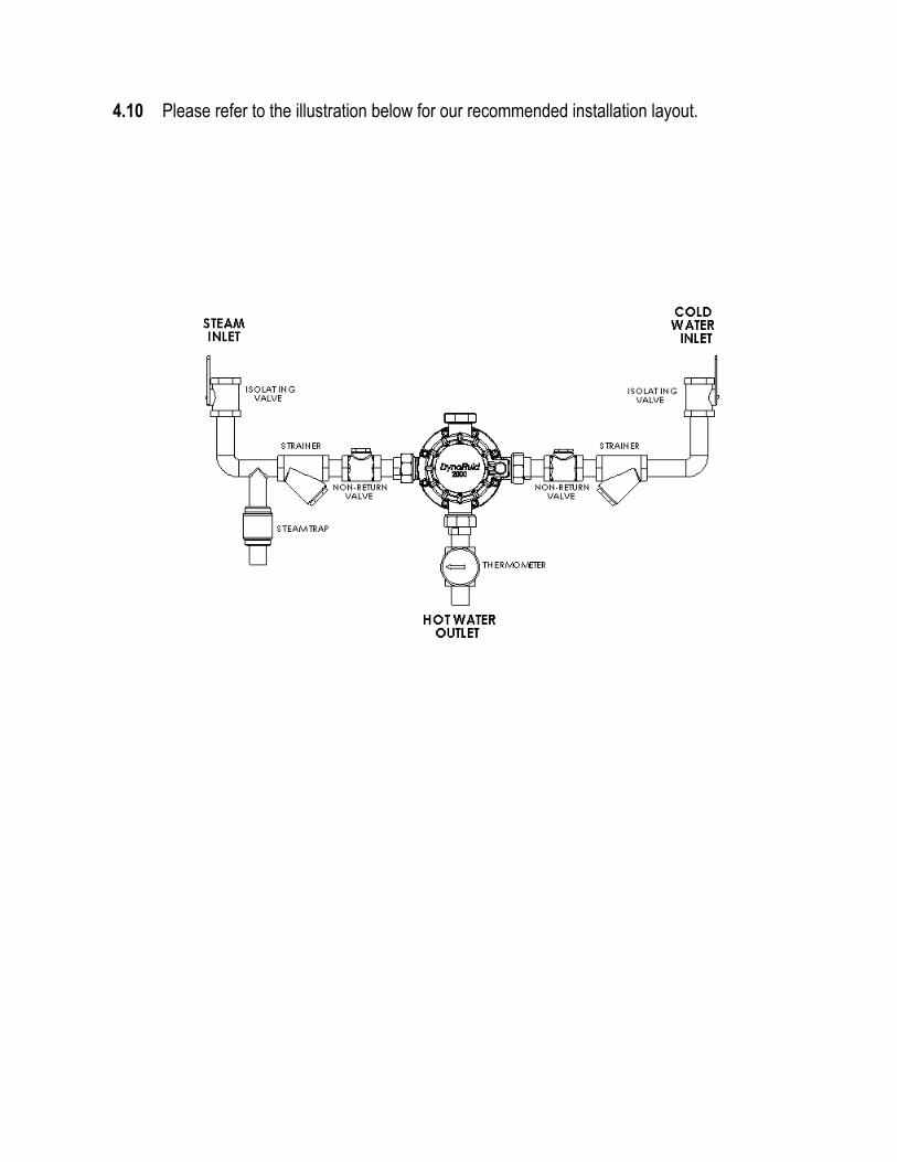
4.10 Please refer to the illustration below for our recommended installation layout.
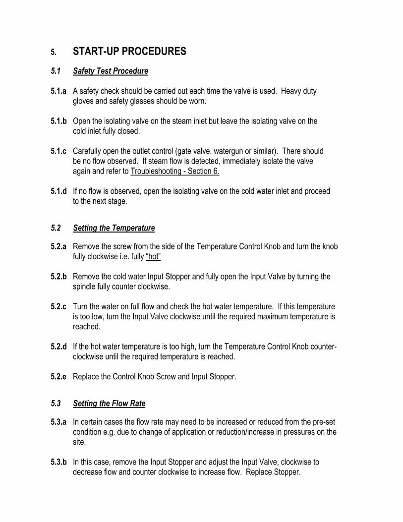
5. START-UP PROCEDURES 5.1 Safety Test Procedure 5.1.a A safety check should be carried out each time the valve is used. Heavy duty gloves and safety glasses should be worn. 5.1.b Open the isolating valve on the steam inlet but leave the isolating valve on the cold inlet fully closed. 5.1.c Carefully open the outlet control (gate valve, watergun or similar). There should be no flow observed. If steam flow is detected, immediately isolate the valve again and refer to Troubleshooting - Section 6. 5.1.d If no flow is observed, open the isolating valve on the cold water inlet and proceed to the next stage. 5.2 Setting the Temperature 5.2.a Remove the screw from the side of the Temperature Control Knob and turn the knob fully clockwise i.e. fully “hot” 5.2.b Remove the cold water Input Stopper and fully open the Input Valve by turning the spindle fully counter clockwise. 5.2.c Turn the water on full flow and check the hot water temperature. If this temperature is too low, turn the Input Valve clockwise until the required maximum temperature is reached. 5.2.d If the hot water temperature is too high, turn the Temperature Control Knob counter- clockwise until the required temperature is reached. 5.2.e Replace the Control Knob Screw and Input Stopper. 5.3 Setting the Flow Rate 5.3.a In certain cases the flow rate may need to be increased or reduced from the pre-set condition e.g. due to change of application or reduction/increase in pressures on the site. 5.3.b In this case, remove the Input Stopper and adjust the Input Valve, clockwise to decrease flow and counter clockwise to increase flow. Replace Stopper.

5.3.c The change in flow rate will have changed the temperature setting. To adjust, turn the Temperature Control Knob, clockwise to increase temperature and counter clockwise to decrease temperature.
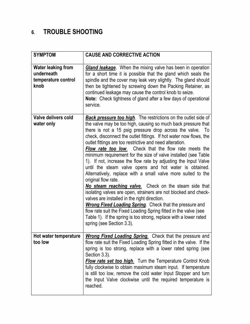
6. TROUBLE SHOOTING SYMPTOM
CAUSE AND CORRECTIVE ACTION
Water leaking from underneath temperature control knob
Gland leakage. When the mixing valve has been in operation for a short time it is possible that the gland which seals the spindle and the cover may leak very slightly. The gland should then be tightened by screwing down the Packing Retainer, as continued leakage may cause the control knob to seize. Note: Check tightness of gland after a few days of operational service.
Valve delivers cold water only
Back pressure too high. The restrictions on the outlet side of the valve may be too high, causing so much back pressure that there is not a 15 psig pressure drop across the valve. To check, disconnect the outlet fittings. If hot water now flows, the outlet fittings are too restrictive and need alteration. Flow rate too low. Check that the flow rate meets the minimum requirement for the size of valve installed (see Table 1). If not, increase the flow rate by adjusting the Input Valve until the steam valve opens and hot water is obtained. Alternatively, replace with a small valve more suited to the original flow rate. No steam reaching valve. Check on the steam side that isolating valves are open, strainers are not blocked and check-valves are installed in the right direction. Wrong Fixed Loading Spring. Check that the pressure and flow rate suit the Fixed Loading Spring fitted in the valve (see Table 1). If the spring is too strong, replace with a lower rated spring (see Section 3.3).
Hot water temperature too low
Wrong Fixed Loading Spring. Check that the pressure and flow rate suit the Fixed Loading Spring fitted in the valve. If the spring is too strong, replace with a lower rated spring (see Section 3.3). Flow rate set too high. Turn the Temperature Control Knob fully clockwise to obtain maximum steam input. If temperature is still too low, remove the cold water Input Stopper and turn the Input Valve clockwise until the required temperature is reached.
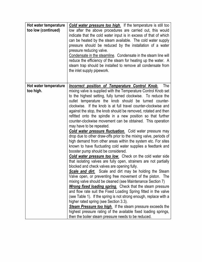
Hot water temperature too low (continued)
Cold water pressure too high. If the temperature is still too low after the above procedures are carried out, this would indicate that the cold water input is in excess of that of which can be heated by the steam available. The cold water supply pressure should be reduced by the installation of a water pressure reducing valve. Condensate in the steamline. Condensate in the steam line will reduce the efficiency of the steam for heating up the water. A steam trap should be installed to remove all condensate from the inlet supply pipework.
Hot water temperature too high.
Incorrect position of Temperature Control Knob. The mixing valve is supplied with the Temperature Control Knob set to the highest setting, fully turned clockwise. To reduce the outlet temperature the knob should be turned counter-clockwise. If the knob is at full travel counter-clockwise and against the stop, the knob should be removed, rotated and then refitted onto the spindle in a new position so that further counter-clockwise movement can be obtained. This operation may have to be repeated. Cold water pressure fluctuation. Cold water pressure may drop due to other draw-offs prior to the mixing valve, periods of high demand from other areas within the system etc. For sites known to have fluctuating cold water supplies a feedtank and booster pump should be considered. Cold water pressure too low. Check on the cold water side that isolating valves are fully open, strainers are not partially blocked and check valves are opening fully. Scale and dirt. Scale and dirt may be holding the Steam Valve open, or preventing free movement of the piston. The mixing valve should be cleaned (see Maintenance Section 7) Wrong fixed loading spring. Check that the steam pressure and flow rate suit the Fixed Loading Spring fitted in the valve (see Table 1). If the spring is not strong enough, replace with a higher rated spring (see Section 3.3). Steam Pressure too high. If the steam pressure exceeds the highest pressure rating of the available fixed loading springs, then the boiler steam pressure needs to be reduced.

Valve passes steam Wrong fixed loading spring. Check that the steam pressure and flow rate suit the Fixed Loading Spring fitted in the valve (see Table 1). If the spring is not strong enough, replace with a higher rated spring (see Section 3.3). Skirted Piston stuck open. The Skirted Piston should move freely. If this is not the case, the piston needs to be removed and cleaned (see Maintenance Section 7). Debris on Steam Valve seat. Debris stuck on or embedded in the steam valve seat needs to be removed and if necessary the Steam Valve replaced (see Maintenance Section 7). Damaged Steam Valve seat. Debris may have passed through the valve, damaging the seat on the way, in which case the Steam Valve needs to be replaced (see Maintenance Section 7).

7. MAINTENANCE 7.1 Regular Maintenance Program
Regular cleaning and maintenance of the Dynafluid 2000 mixing valve is essential to prevent the build up of pipeline debris and limescale on critical moving parts. We recommend that the valve is inspected and routinely maintained at least once
every twelve months. In particularly hard water areas the frequency should be increased to once every six months.
7.2 Pre-maintenance Safety Procedure Before carrying out any maintenance procedures, isolate the incoming services by
closing the steam inlet valve and the water inlet valve. Discharge the contents of the valve by opening the outlet until the water flow stops. Wait for the valve to cool down.
7.3 Maintenance Procedure - ½” and ¾” Valves (see Section 7.4 for larger sizes) (PLEASE REFER TO DRAWINGS AND DESCRIPTIONS IN SECTION 8.1 & 8.2) 7.3.a Maintenance can be carried out on site using standard plumbing tools. Alternatively, undo the 3 union joints and remove mixing valve and move it to a maintenance area. 7.3.b Remove Temperature Control Knob by loosening the Control Knob Screw with a 5mm allen key and pulling the knob away from the valve. 7.3.c Remove the Top Cap by unscrewing counter clockwise and withdraw the large Fixed Loading Spring and smaller Variable Loading Spring. 7.3.d Unscrew the Packing Retainer from the Top Cap and remove the spindle. Remove the gland packing (2 black rings) using a flat headed screw driver. Insert two new gland packings from the Repair Kit into the Top cap and re-assemble the spindle and Packing Retainer. 7.3.e Replace the Top Cap Gasket with new gasket from the Repair Kit. 7.3.f Remove the Retaining Plate using a box wrench. As the Piston rotates freely, it will be
necessary to hold the Piston tight by placing a ¼” diameter bar into one of the valve outlets and through one of the holes in the side of the Piston.
7.3.g Lift out the Steam Valve and its tension spring, and the Lower Piston Plate. 7.3.h Unscrew three stainless steel screws and remove the Silencer Plate.

7.3.i Unscrew the Valve Seat Housing using a socket plug. Ensure that the copper washer is removed at the same time. 7.3.j Unscrew the Cover to Base Screws using a 5mm allen key, and remove Cover from Base. 7.3.k Remove the main Cover to Base Seal and replace with new seal from Repair Kit, ensuring that both it and the sealing surfaces are free from debris, dust etc. Replace seal around the pressure relief/location tube. 7.3.l Remove the Piston and Sleeve. Clean all surfaces thoroughly using a descalent if deposits of limescale are present. Re-fit the Sleeve and Piston, ensuring both parts slide and rotate freely. 7.3.m Re-fit the Cover to the Base ensuring that both seals are properly located. Secure the Cover using the new screws from the Repair Kit tightening screws on opposite sides to the valve in turn. 7.3.n Fit the new Valve Seat Housing from the Repair Kit and tighten with a socket plug. 7.3.o Re-fit the Silencer Plate with the three screws and re-fit the Lower Piston Plate. 7.3.p Fit new Steam Valve and its tension spring from the Repair Kit, ensuring that it is completely clean. 7.3.q Re-fit the Retaining Plate using a box wrench, and check that the Piston can still rotate fully. 7.3.r Re-fit the small Variable Loading Spring and larger Fixed Loading Spring. Fit Top cap to Cover, screw down and tighten. 7.3.s Re-fit Temperature Control Knob and secure with screw. 7.4 Maintenance Procedure - 1” and 1½” Valves (PLEASE REFER TO DRAWINGS AND DESCRIPTIONS IN SECTION 8.3 & 8.4) 7.4.a Maintenance can be carried out on site using standard plumbing tools. Alternatively, undo the three union joints and remove mixing valve and move it to a maintenance area. 7.4.b Remove Temperature Control Knob by loosening the Control Knob Screw with a 5mm
allen key (flat headed screwdriver for the 1½” valve) and pulling the knob away from the valve.
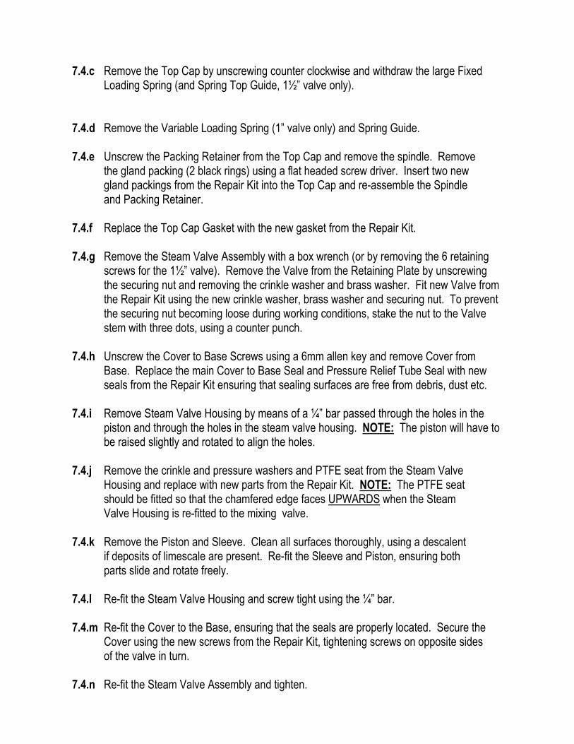
7.4.c Remove the Top Cap by unscrewing counter clockwise and withdraw the large Fixed Loading Spring (and Spring Top Guide, 1½” valve only). 7.4.d Remove the Variable Loading Spring (1” valve only) and Spring Guide. 7.4.e Unscrew the Packing Retainer from the Top Cap and remove the spindle. Remove the gland packing (2 black rings) using a flat headed screw driver. Insert two new gland packings from the Repair Kit into the Top Cap and re-assemble the Spindle
and Packing Retainer. 7.4.f Replace the Top Cap Gasket with the new gasket from the Repair Kit. 7.4.g Remove the Steam Valve Assembly with a box wrench (or by removing the 6 retaining
screws for the 1½” valve). Remove the Valve from the Retaining Plate by unscrewing the securing nut and removing the crinkle washer and brass washer. Fit new Valve from the Repair Kit using the new crinkle washer, brass washer and securing nut. To prevent the securing nut becoming loose during working conditions, stake the nut to the Valve stem with three dots, using a counter punch.
7.4.h Unscrew the Cover to Base Screws using a 6mm allen key and remove Cover from
Base. Replace the main Cover to Base Seal and Pressure Relief Tube Seal with new seals from the Repair Kit ensuring that sealing surfaces are free from debris, dust etc.
7.4.i Remove Steam Valve Housing by means of a ¼” bar passed through the holes in the
piston and through the holes in the steam valve housing. NOTE: The piston will have to be raised slightly and rotated to align the holes.
7.4.j Remove the crinkle and pressure washers and PTFE seat from the Steam Valve Housing and replace with new parts from the Repair Kit. NOTE: The PTFE seat should be fitted so that the chamfered edge faces UPWARDS when the Steam Valve Housing is re-fitted to the mixing valve. 7.4.k Remove the Piston and Sleeve. Clean all surfaces thoroughly, using a descalent if deposits of limescale are present. Re-fit the Sleeve and Piston, ensuring both parts slide and rotate freely. 7.4.l Re-fit the Steam Valve Housing and screw tight using the ¼” bar. 7.4.m Re-fit the Cover to the Base, ensuring that the seals are properly located. Secure the Cover using the new screws from the Repair Kit, tightening screws on opposite sides of the valve in turn. 7.4.n Re-fit the Steam Valve Assembly and tighten.

7.4.o Re-fit the Spring Guides, Variable Loading Spring (1” only) and Fixed Loading Spring. Fit Top Cap to Cover and tighten. 7.4.p Re-fit Temperature Control Knob and secure with screw.

8 SPARE PARTS 8.1 Dynafluid 2000 – ½”
PART NUMBER DESCRIPTION PART NUMBER DESCRIPTION 2000-28-1/2DYNA NAMEPLATE 2000-8-1/2J VARIABLE SPRING 2000-51-1/2J CONTROL KNOB 2000-21-1/2J STEAM VALVE SPRING 2000-27-1/2J CONTROL KNOB SCREW 2000-57-3/4J STEAM VALVE & SPRING 2000-53-1/2J TOP CAP PACKING SET 2000-52-1/2J PISTON PLATES 2000-6-1/2J TOP CAP 2000-56-3/4J VALVE SEAT HOUSING ASSEMBLY 2000-13-1/2J TOP CAP GASKET 2000-4-1/2J SKIRTED PISTON 2000-9-1/2J SPINDLE 2000-22-3/4J SLEEVE 2000-36-1/2J (2) CONTROL KNOB STOPS 2000-58-1/2J COVER TO BASE SEAL 2000-61-1/2J COVER SCREWS & WASHERS 2000-23-1/2J RELIEF/LOCATION TUBE 2000-50-1/2J COVER ASSEMBLY 2000-1-1/2J BODY 2000-62-1/2J SEALING PLUG & WASHER 2000-26-1/2J UNION GASKET 2000-55-1/2J INPUT VALVE & PACKING 2000-60-1/2J UNION ASSEMBLY 2000-54-1/2J INPUT STOP & WASHER 2000-59-1/2J BRACKET AND SCREWS 2000-7A-1/2J FIXED SPRING 0-50 PSIG 2000-100-1/2J VALVE REPAIR KIT 2000-7-1/2J FIXED SPRING 50-100 PSIG 2000-7B-1/2J FIXED SPRING 100-150 PSIG

8.2 Dynafluid 2000 – ¾”
PART NUMBER DESCRIPTION PART NUMBER DESCRIPTION 2000-28-1/2DYNA NAMEPLATE 2000-8-3/4J VARIABLE SPRING 2000-51-1/2J CONTROL KNOB 2000-21-1/2J STEAM VALVE SPRING 2000-27-1/2J CONTROL KNOB SCREW 2000-57-3/4J STEAM VALVE & SPRING 2000-53-1/2J TOP CAP PACKING SET 2000-52-1/2J PISTON PLATES 2000-6-1/2J TOP CAP 2000-56-3/4J VALVE SEAT HOUSING ASSEMBLY 2000-13-1/2J TOP CAP GASKET 2000-4-3/4J SKIRTED PISTON 2000-9-3/4J SPINDLE 2000-22-3/4J SLEEVE 2000-36-1/2J CONTROL KNOB STOPS 2000-58-3/4J COVER TO BASE SEAL 2000-61-1/2J COVER SCREWS & WASHERS 2000-23-1/2J RELIEF/LOCATION TUBE 2000-50-3/4J COVER ASSEMBLY 2000-1-3/4J BODY 2000-62-3/4J SEALING PLUG & WASHER 2000-26-1/2J UNION GASKET 2000-55-1/2J INPUT VALVE & PACKING 2000-60-3/4J UNION ASSEMBLY 2000-54-1/2J INPUT STOP & WASHER 2000-59-1/2J BRACKET AND SCREWS 2000-7A-3/4J FIXED SPRING 0-50 PSIG 2000-100-3/4J VALVE REPAIR KIT 2000-7-3/4J FIXED SPRING 50-100 PSIG 2000-7B-3/4J FIXED SPRING 100-150 PSIG
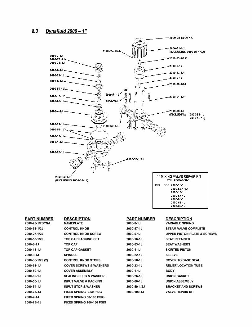
8.3 Dynafluid 2000 – 1”
PART NUMBER DESCRIPTION PART NUMBER DESCRIPTION 2000-28-1/2DYNA NAMEPLATE 2000-8-1J VARIABLE SPRING 2000-51-1/2J CONTROL KNOB 2000-57-1J STEAM VALVE COMPLETE 2000-27-1/2J CONTROL KNOB SCREW 2000-5-1J UPPER PISTON PLATE & SCREWS 2000-53-1/2J TOP CAP PACKING SET 2000-16-1J SEAT RETAINER 2000-6-1J TOP CAP 2000-63-1J SEAT WASHERS 2000-13-1J TOP CAP GASKET 2000-4-1J SKIRTED PISTON 2000-9-1J SPINDLE 2000-22-1J SLEEVE 2000-36-1/2J (2) CONTROL KNOB STOPS 2000-58-1J COVER TO BASE SEAL 2000-61-1J COVER SCREWS & WASHERS 2000-23-1J RELIEF/LOCATION TUBE 2000-50-1J COVER ASSEMBLY 2000-1-1J BODY 2000-62-1J SEALING PLUG & WASHER 2000-26-1J UNION GASKET 2000-55-1J INPUT VALVE & PACKING 2000-60-1J UNION ASSEMBLY 2000-54-1J INPUT STOP & WASHER 2000-59-1/2J BRACKET AND SCREWS 2000-7A-1J FIXED SPRING 0-50 PSIG 2000-100-1J VALVE REPAIR KIT 2000-7-1J FIXED SPRING 50-100 PSIG 2000-7B-1J FIXED SPRING 100-150 PSIG

8.4 Dynafluid 2000 – 1½”
PART NUMBER DESCRIPTION PART NUMBER DESCRIPTION 2000-28-1/2DYNA NAMEPLATE 2000-66-11/2J STEAM VALVE NUT & WASHER 2000-51-11/2J CONTROL KNOB 2000-57-11/2J STEAM VALVE & SPRING 2000-27-1/2J CONTROL KNOB SCREW 2000-5-11/2J UPPER PISTON PLATE & SCREWS 2000-53-1/2J TOP CAP PACKING SET 2000-16-11/2J SEAT RETAINER 2000-6-11/2J TOP CAP 2000-63-11/2J SEAT WASHERS 2000-13-11/2J TOP CAP GASKET 2000-4-11/2J SKIRTED PISTON 2000-9-11/2J SPINDLE 2000-22-11/2J SLEEVE 2000-36-1/2J (2) CONTROL KNOB STOPS 2000-58-11/2J COVER TO BASE SEAL 2000-61-1J COVER SCREWS & WASHERS 2000-23-11/2J RELIEF/LOCATION TUBE 2000-50-11/2J COVER ASSEMBLY 2000-1-11/2J BODY 2000-62-11/2J SEALING PLUG & WASHER 2000-26-11/2J UNION GASKET 2000-55-11/2J INPUT VALVE & PACKING 2000-60-11/2J UNION ASSEMBLY 2000-54-11/2J INPUT STOP & WASHER 2000-59-11/2J BRACKET AND SCREWS 2000-7A-11/2J FIXED SPRING 0-50 PSIG 2000-100-11/2J VALVE REPAIR KIT 2000-7-11/2J FIXED SPRING 50-100 PSIG 2000-7B-11/2J FIXED SPRING 100-150 PSIG
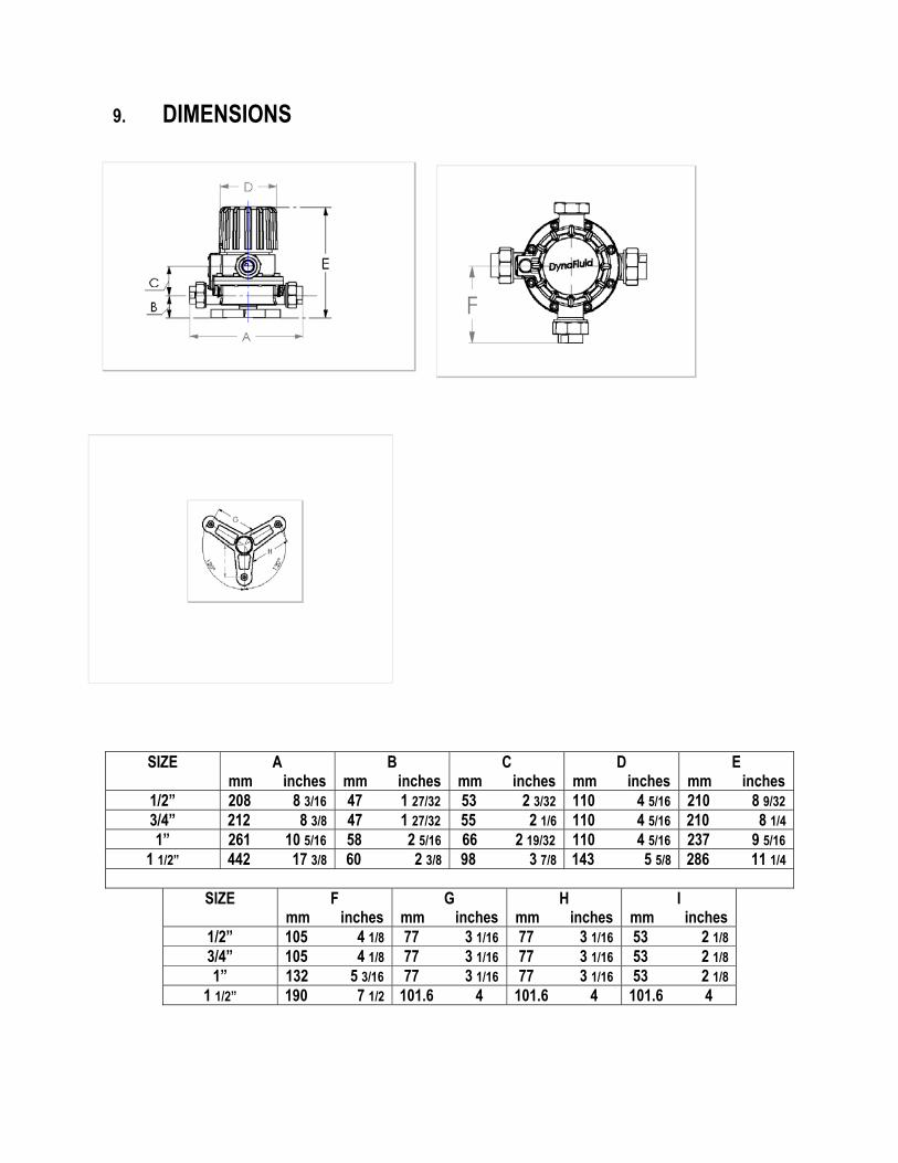
9. DIMENSIONS
SIZE A mm inches
B mm inches
C mm inches
D mm inches
E mm inches
1/2” 208 8 3/16 47 1 27/32 53 2 3/32 110 4 5/16 210 8 9/32 3/4” 212 8 3/8 47 1 27/32 55 2 1/6 110 4 5/16 210 8 1/4 1” 261 10 5/16 58 2 5/16 66 2 19/32 110 4 5/16 237 9 5/16
1 1/2” 442 17 3/8 60 2 3/8 98 3 7/8 143 5 5/8 286 11 1/4
SIZE F mm inches
G mm inches
H mm inches
I mm inches
1/2” 105 4 1/8 77 3 1/16 77 3 1/16 53 2 1/8 3/4” 105 4 1/8 77 3 1/16 77 3 1/16 53 2 1/8 1” 132 5 3/16 77 3 1/16 77 3 1/16 53 2 1/8
1 1/2” 190 7 1/2 101.6 4 101.6 4 101.6 4