
DynaCon® Standard Conveyor Assembly Instructions
24
Assembly Instructions Revision 6: 2020
Transcript of DynaCon® Standard Conveyor Assembly Instructions

Assembly Instructions
Revision 6: 2020

2
TABLE OF CONTENTS
Important Information 4
Warranty 4
Limit of Liability 4
For Your Records 4
Operation 4
Maintenance 5
When Your Shipment Arrives 5
Tools & Personnel Required 5
Conveyor Assembly 6
Leg Supports 7
Low Rider Caster Supports 7
Peg Leg Supports 7
Upright Leg Supports 8
4-10” Wide “H” Base Leg Supports 8
12-72” Wide “T” Base Leg Supports 8
Radius Turn Legs 10
Leg Straps 10
MayTec Supports 12
Perpendicular Brackets 12
Parallel Brackets 13
Horizontal and Vertical Brackets 14
Belt Installation 15
Removing the Feed End 15
Standard Feed End 15
Heavy Duty Feed End 15

3
Inserting the Belt 16
Standard Belting 16
Belting with Hold Down Tabs 16
Radius Turn Belting 17
Lacing the Belt 18
Removing the Lacing Rod 18
Standard Belting 18
Abrasion Resistant Lacing Rods 18
Radius Turn Lacing Rod 18 Re-installing the Lacing Rod 19 Standard Belting Lacing Rod 19 Abrasion Resistant Lacing Rod 19 Radius Turn Lacing Rod 19
Belt Break In 20
Replacing the Feed End 21
Standard Feed End 21
Heavy Duty Feed End 21
Replacement Parts 22
Grey Side Panels 22
Belt Supports & Belt Paths 22
Miscellaneous Parts 23

4
IMPORTANT INFORMATION The information contained in this manual is provided only as an aid and service to our customers. Dynamic Conveyor Corporation does not warrant the accuracy or applicability of such information and is not specifi-cally responsible for property damage and/or per-sonal injury inflicted directly or indirectly, or for dam-ages and/or failures caused by improper application, installation, operation, abuse and/or misuse of its products whether or not based on information con-tained herein. WARRANTY Dynamic Conveyor Corporation warrantees products of its own manufacture for a period of five (5) years on the DynaCon® product line. Dynamic Conveyor Corporation will repair or replace any products that have failed under normal use due to faulty material or defective workmanship. Components, products and conveyors not manufactured by Dynamic Conveyor will be covered by the manufacturer’s warranty. No other warranty is expressed or implied unless other-wise set forth in writing and approved by representa-tive duly authorized to extend such approval by Dy-namic Conveyor Corporation. Additional note: Any Dynamic Conveyor Corporation equipment/systems that are physically altered with-out direct authorization from Dynamic Conveyor Cor-poration shall be termed “Product altered without au-thorization: no warranty or liability applies to that al-tered equipment/system”. LIMIT OF LIABILITY In no event shall Dynamic Conveyor Corporation be li-able for any special, indirect, incidental, or conse-quential damages of any character, including but not limited to loss of production facilities or equipment, lost profits, property damage, lost production, or any consequential downtime, whether suffered by distrib-utor or third party, irrespective of whether claims or actions for such damages are based upon contract, warranty, tort (including negligence), strict liability, or otherwise.
FOR YOUR RECORDS Thank you for your investment in a DynaCon Con-veyor. We believe our product will become a vital step in your production process and it will grow with your changing needs. Please take the time to complete the following infor-mation as thoroughly as possible. It will prove helpful when you contact customer service in the event you have any questions about assembly, installation or op-eration. Date of Shipment: __________________________ Serial Number: _____________________________ Model Number: ____________________________ DYNAMIC CONVEYOR CORPORATION 5980 Grand Haven Road Norton Shores, Michigan 49441 231.798.1483 [email protected] SUPPORT Find additional support on our website at https://www.dynamicconveyor.com/products/parts-conveyor/parts-service/
OPERATION DynaCon Conveyors are designed to operate continu-ously in a forward direction, i.e., product is conveyed toward and discharged off of the motorized module (Drive Module), with capability for occasional revers-ing. If your conveyor requires continuous operation in a reverse direction, please contact Dynamic Conveyor for recommendations.

5
MAINTENANCE DynaCon Conveyors are designed to be easy to main-tain and repair. To ensure proper operation, we rec-ommend periodically inspecting the frame, motor, and belt paths for wear and damage. Belt tensioning may be needed shortly after initial in-stallation as the belt can stretch. Under ordinary operating conditions, the belt and conveyor frame should be checked for any abnormal wear or stress (i.e. continuous grooves, cracks, etc.). No lubrication of the belt or belt paths is necessary. Under high speed or continuous use conditions, more frequent inspection is encouraged. Under dirty or greasy operating conditions, a daily in-spection along with periodic cleaning of the belt, belt paths, and belt supports is recommended. This will require removal of the belt in most cases. (Note: DynaCon Conveyors are not intended for use in abrasive environments.) Necessary steps should be taken to correct any prob-lems as soon as they are discovered. Any questions or concerns may be directed to your local sales repre-sentative and/or our customer service department. WHEN YOUR SHIPMENT ARRIVES The packing slip will be accompanied with a drawing of your conveyor configuration. The drawing will prove helpful when assembling your conveyor.
The drawing will look something like the picture be-low.
TOOLS & PERSONNEL REQUIRED Accompanying this Assembly Instructions booklet is a 7/32” Bondhus Bit for button-head cap screws. Every DynaCon Conveyor requires a minimum of two assemblers. Locate an area where you will have ample space to lay out the conveyor. Your DynaCon Conveyor configuration may differ from the following examples shown. If you have multiple conveyors shipped to you, col-ored dots on the inside of the modules will indicate each conveyor. Follow the step-by-step directions on the proceeding pages.

6
CONVEYOR ASSEMBLY
Lay conveyor out in sections not to exceed six (6) modules.
1 – Remove extra screws (SCA381) for later use. 2 – Loosen screws so connecting plate is free to move out slightly. 3 – Align bosses on modules with connecting plate holes, and use screws from step 1 to attach.
All modules will connect in this manner.
Do not over-tighten connecting screws.
Non-Shimmed Module Shimmed Module
Some belt styles will require shimmed modules.
Never connect a shimmed module to a non-shimmed module.
7
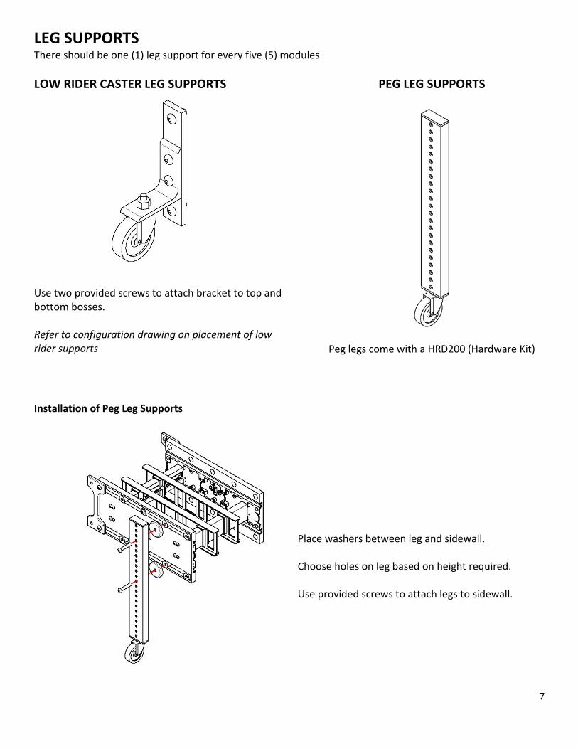
LEG SUPPORTS There should be one (1) leg support for every five (5) modules LOW RIDER CASTER LEG SUPPORTS
Use two provided screws to attach bracket to top and bottom bosses. Refer to configuration drawing on placement of low rider supports
PEG LEG SUPPORTS
Peg legs come with a HRD200 (Hardware Kit)
Installation of Peg Leg Supports
Place washers between leg and sidewall. Choose holes on leg based on height required. Use provided screws to attach legs to sidewall.

8
UPRIGHT LEG SUPPORTS Crossbar Requirement by Conveyor Width & Height “H” Base Supports for 4-10” Wide Conveyors • 24” to 60” leg supports require 1 cross bar (Below) • 72” to 96” leg supports require 2 cross bars • 108” and taller leg supports require 3 cross bars
and must be permanently secured to the floor
“T” Base Supports for 12-72” Wide Conveyors • 24” to 60” leg supports require 2 cross bars (Be-
low) • 72” to 96” leg supports require 3 cross bars • 108” and taller leg supports require 4 cross bars
and must be permanently secured to the floor
Installation of Upright Leg Supports
Remove center screws from all crossbar(s)
9
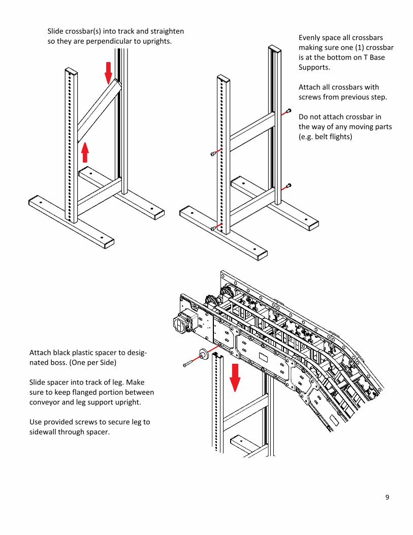
Slide crossbar(s) into track and straighten so they are perpendicular to uprights.
Evenly space all crossbars making sure one (1) crossbar is at the bottom on T Base Supports. Attach all crossbars with screws from previous step. Do not attach crossbar in the way of any moving parts (e.g. belt flights)
Attach black plastic spacer to desig-nated boss. (One per Side) Slide spacer into track of leg. Make sure to keep flanged portion between conveyor and leg support upright. Use provided screws to secure leg to sidewall through spacer.

10
Installation of Leg Straps
Make sure that screw in tightening knob is flush with nut and threads are not exposed.
Non-Flush Screw
Attach extrusion covers to top of leg supports
Radius Turn Legs If your conveyor has a radius turn module, attach provided brackets with provided screws. Set the module onto the holding brackets.
Flush Screw

11
OPTIMUM RANGE FOR LEG STRAPS
Loosely screw the leg strap to con-veyor. The strap should be able to swivel around the screw. Refer to the optimum range for leg strap placement to guide you on where to place leg strap on module.
Insert diamond flange into track. Tighten nut inside track.
The flange will twist and clamp onto the leg holding it in place. Tighten the screw at the top of the strap.
Cut-away views for instructional purposes
12
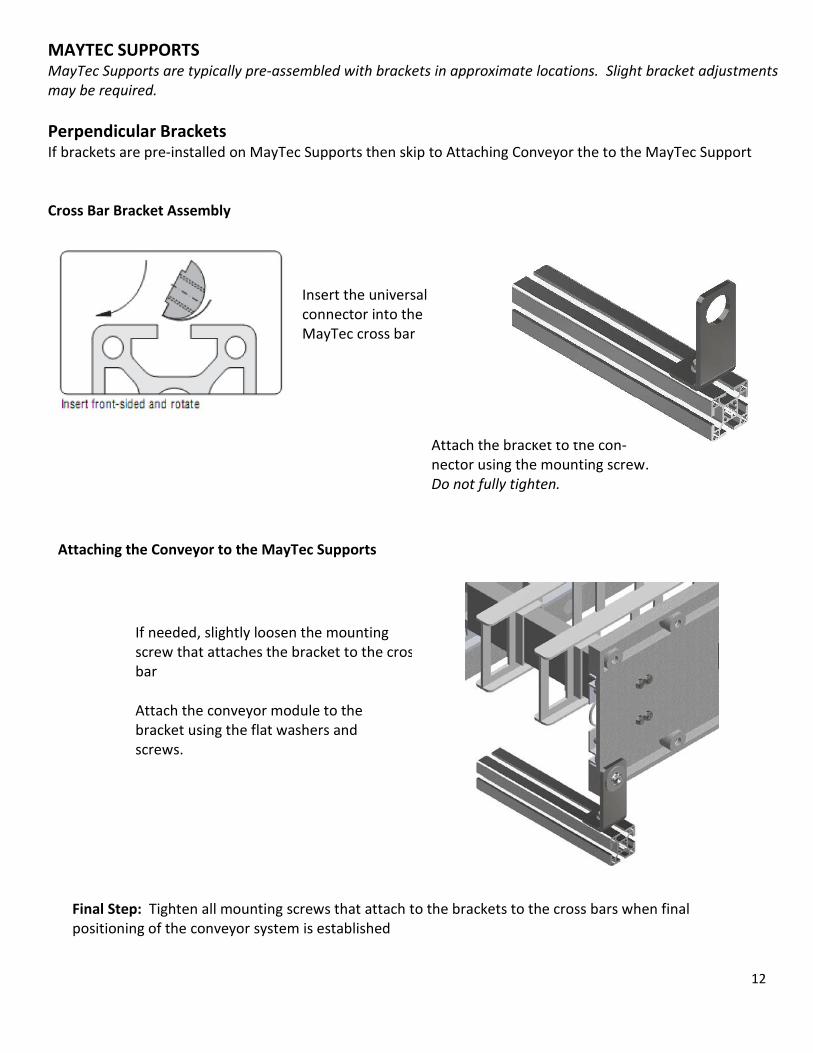
MAYTEC SUPPORTS MayTec Supports are typically pre-assembled with brackets in approximate locations. Slight bracket adjustments may be required. Perpendicular Brackets If brackets are pre-installed on MayTec Supports then skip to Attaching Conveyor the to the MayTec Support Cross Bar Bracket Assembly
Attach the bracket to the con-nector using the mounting screw. Do not fully tighten.
Insert the universal connector into the MayTec cross bar
Attaching the Conveyor to the MayTec Supports
If needed, slightly loosen the mounting screw that attaches the bracket to the cros bar Attach the conveyor module to the bracket using the flat washers and screws.
Final Step: Tighten all mounting screws that attach to the brackets to the cross bars when final positioning of the conveyor system is established
13
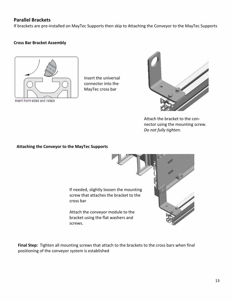
Parallel Brackets If brackets are pre-installed on MayTec Supports then skip to Attaching the Conveyor to the MayTec Supports Cross Bar Bracket Assembly
Insert the universal connector into the MayTec cross bar
Attach the bracket to the con-nector using the mounting screw. Do not fully tighten.
Attaching the Conveyor to the MayTec Supports
If needed, slightly loosen the mounting screw that attaches the bracket to the cross bar Attach the conveyor module to the bracket using the flat washers and screws.
Final Step: Tighten all mounting screws that attach to the brackets to the cross bars when final positioning of the conveyor system is established

14
Horizontal or Vertical Brackets If brackets are pre-installed on MayTec Supports then skip to Attaching the Conveyor to the MayTec Supports Cross Bar Bracket Assembly
Insert the universal
connector into the MayTec cross bar
Attach the bracket to the con-nector using the mounting screw. Do not fully tighten.
Attaching the Conveyor to the MayTec Supports
If needed, slightly loosen the mounting screw that attaches the bracket to the cross bar Attach the conveyor module to the bracket using the flat washers and screws.
Final Step: Tighten all mounting screws that attach to the brackets to the cross bars when final positioning of the conveyor system is established
15
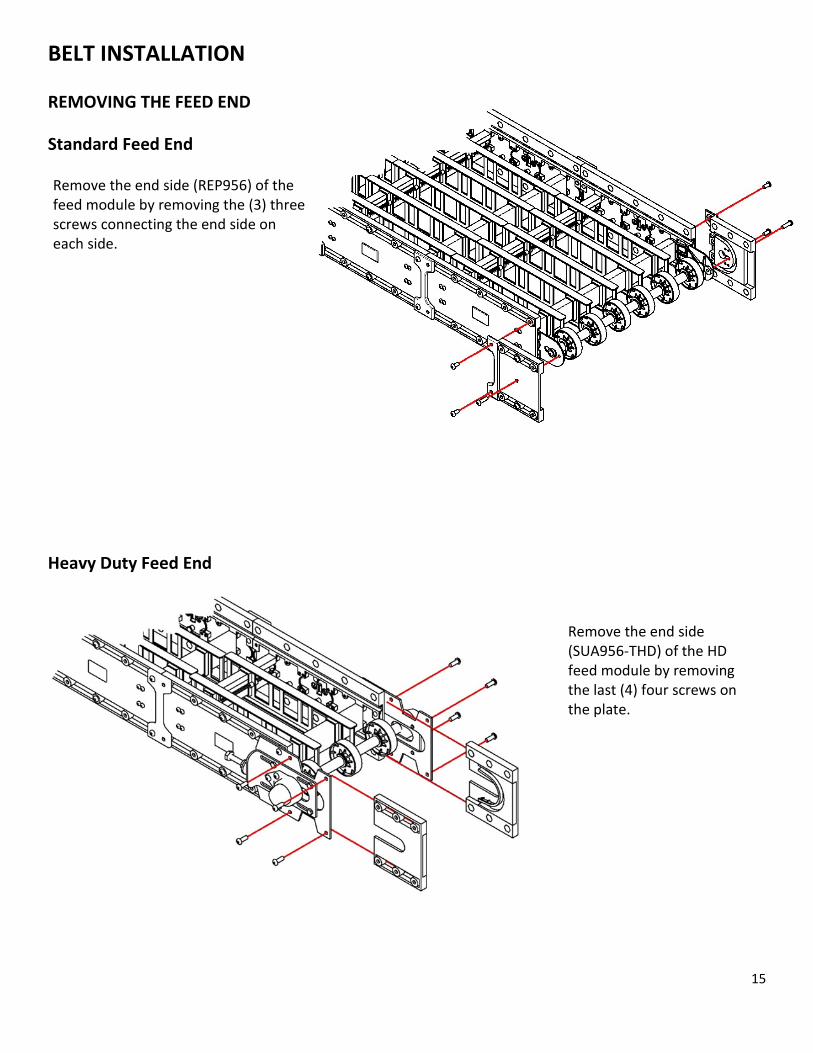
BELT INSTALLATION REMOVING THE FEED END
Standard Feed End
Heavy Duty Feed End
Remove the end side (REP956) of the feed module by removing the (3) three screws connecting the end side on each side.
Remove the end side (SUA956-THD) of the HD feed module by removing the last (4) four screws on the plate.

16
INSERTING THE BELT Standard Belting Belting with Hold Down Tabs
Guide belt into the top belt path. Slide belt all the way down to drive sprockets. It should take very little effort to slide the belt onto the conveyor.
Slide the tabs onto the floating belt support. (Typically this is the center belt support.) It should take very little effort to slide the belt onto the conveyor.
17
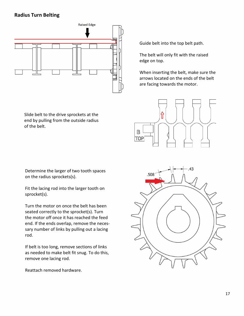
Radius Turn Belting
Guide belt into the top belt path. The belt will only fit with the raised edge on top. When inserting the belt, make sure the arrows located on the ends of the belt are facing towards the motor.
Determine the larger of two tooth spaces on the radius sprockets(s). Fit the lacing rod into the larger tooth on sprocket(s). Turn the motor on once the belt has been seated correctly to the sprocket(s). Turn the motor off once it has reached the feed end. If the ends overlap, remove the neces-sary number of links by pulling out a lacing rod.
If belt is too long, remove sections of links as needed to make belt fit snug. To do this, remove one lacing rod.
Reattach removed hardware.
Slide belt to the drive sprockets at the end by pulling from the outside radius of the belt.

18
LACING THE BELT
Removing the Lacing Rod
Once belt is at drive end, make sure the drive sprockets are properly seated in the belt. Turn on motor. If your belt has Hold Down Tabs, make sure the tabs are centered on the bottom support as well. Turn motor off once belt is near the feed end.
If belt is too long, remove rows of links as needed to make belt fit snug by removing one lacing rod.
Standard Belting & Abrasion Resistant Lacing Rod To remove lacing rods cut off the head of lacing rod and push rod out.
Radius Turn Lacing Rod Insert screwdriver on top of the belt and twist. Push rod through the hole until you can grab it and pull it the rest of the way.

19
Re-Installing the Lacing Rod
Radius Turn Lacing Rod Cut lacing rods 0.6 in (15mm) shorter than overall length. Insert rod as far as possible when belt ends join. Use a screw driver to ensure rod is fully inserted.
Abrasion Resistant Lacing Rod Insert white lacing rod where belt ends join. Then insert lacing rod ends by applying pressure down and away with a screwdriver.
Standard Belting Lacing Rod Join belt ends together so the hinges are aligned.
Insert the rod through the hinges, leaving only the rod head protruding.
Use a screwdriver to push the rod head into the belt while applying pressure down and away from the Snap-Lock.

20
BELT BREAK IN The belt can lengthen after the break-in period. To adjust for the change in belt length, remove feed end. Loosen (do not remove) screws that connect the shaft to module. Move shaft back to take up extra belt length. Reattach removed hardware.
Enlarged for clarity
On the spacer (PLD702) there are two posts that maintain the tailstock position. Make sure they are fitted into the adjustment holes on the tailstock bracket (PLD701).
Adjustment Holes

21
REPLACING THE FEED END
Standard Feed End
Heavy Duty Feed End
Reattach take-up sidewall & hardware. To adjust the feed end, loosen the four (4) screws on the adjustable take up plate. Either loosen or tighten the adjustable take up screw on both sides of the con-veyor. Make sure each side is tightened equally. It may help to measure the adjustable take up screws. The belt does not need to be exces-sively tight.
Reattach belt paths and feed end. The belt does not have to be ex-cessively tight.

22
REPLACEMENT PARTS
GREY SIDE PANELS
REP952 – 17.5” Straight Connector Wall w/Belt Path REP956 – 6.5” Feed End (Belt Access Panel) Connector Wall w/Belt Path REP960 – 6.5” Straight Connector Wall w/Belt Path REP963 – 30 Degree Connector Wall w/Belt Path REP966 – 45 Degree Connector Wall w/Belt Path
SUI952-E – Non Motorized Side & Drive End w/Belt Path SUI952-EE – External Motor Drive Side Connector Wall w/Belt Path SUI952-OR – Internal Variable Speed Drive Side Connector Wall w/Belt Path SUR952-E – Non Motorized Side Connector Wall w/Belt Path (Radius Turn) SUR952-EE – External Motor Drive Side Connector Wall w/Belt Path (Radius Turn only)
KIT970 – 17.5” Retaining Flange Kits (2pcs) KIT971 – 6.5” Retaining Flange Kits (2pcs) KIT972 – 30 Degree Outside Flange Kits (2pcs) KIT929 – 30 Degree Inside Flange Kits (2pcs) KIT973 – 45 Degree Outside Flange Kits (2pcs) KIT925 – 45 Degree Inside Flange Kits (2pcs) KIT3_ _ – Feed End Retaining Kit w/Feed Shield *( _ _ dictates conveyor width)*
BELT SUPPORTS & BELT PATHS
PLC954 – 17.5” Straight Connector Belt Support PLC957 – 10 ¾” Drive Module Belt Support PLC958 – Drive Module Belt Support –End Turn PLC962 – 6.5” Straight Connector Belt Support PLC965 – 30 Degree Connector Belt Support PLC968 – 45 Degree Connector Belt Support PLD953 – 17.5” Straight Connector Belt Path PLD953-C – 12 ¾” Drive Module Beth Path PLD955 – 6.5” Feed End (Belt Access Panel) Side Wall Belt Path PLD955-D – Drive End Belt Path PLD961 – 6.5” Straight Connector Belt Path PLD964 – 30 Degree Connector Belt Path PLD967 – 45 Degree Connector Belt Path PLR955 – 6.5” Feed End Side Wall (Belt Access Panel) Radius Turn Belt Path KIT955-HDT – Heavy Duty Feed End Belt Path (Pair)
23
MISCELLANEOUS PARTS
GPA191 – 1” Bore Drive Sprocket – Standard – 4.1” pitch diameter GPA192 – 1” Bore Drive Sprocket – Radius Turn – 3.9” pitch diameter GPC911 – Threaded Hex Plug 3/8-16 PLC906 – Plastic Rivet PLD703 – 1” Bore Idler Wheel REP916 – 2 Hole Connector REP930 – 4 Hole Connector KIT616 – 15” Leg Straps (2pcs) KIT231 – 30” Leg Straps (2pcs) KIT945 – Leg Connector Kit – used with “LH Series” Leg Set HRD200 – Leg Connector Kit – used with “Peg Leg” Leg Set PLD711 – Black E-Clip PLD712 – Plastic Key used with Drive Sprockets GPA211 – 1” Bore Wood Bearing GPA224 – Internal Drive Belt GPA283 – Spider KIT947 – Wire Management Clip w/ Hardware KIT940 – Clear Cover Clip w/Hardware (pair)

24