Dyka - PVC-U Technical Specifications
56
PVC-u Technical Specifications Reference Issue Date: November 1997 Version: 001 Library: ......................................................................................
-
Upload
rogerchetcuti -
Category
Documents
-
view
782 -
download
26
Transcript of Dyka - PVC-U Technical Specifications
PVC-uTechnicalSpecifications
Reference
Issue Date: November 1997
Version: 001
Library: ......................................................................................
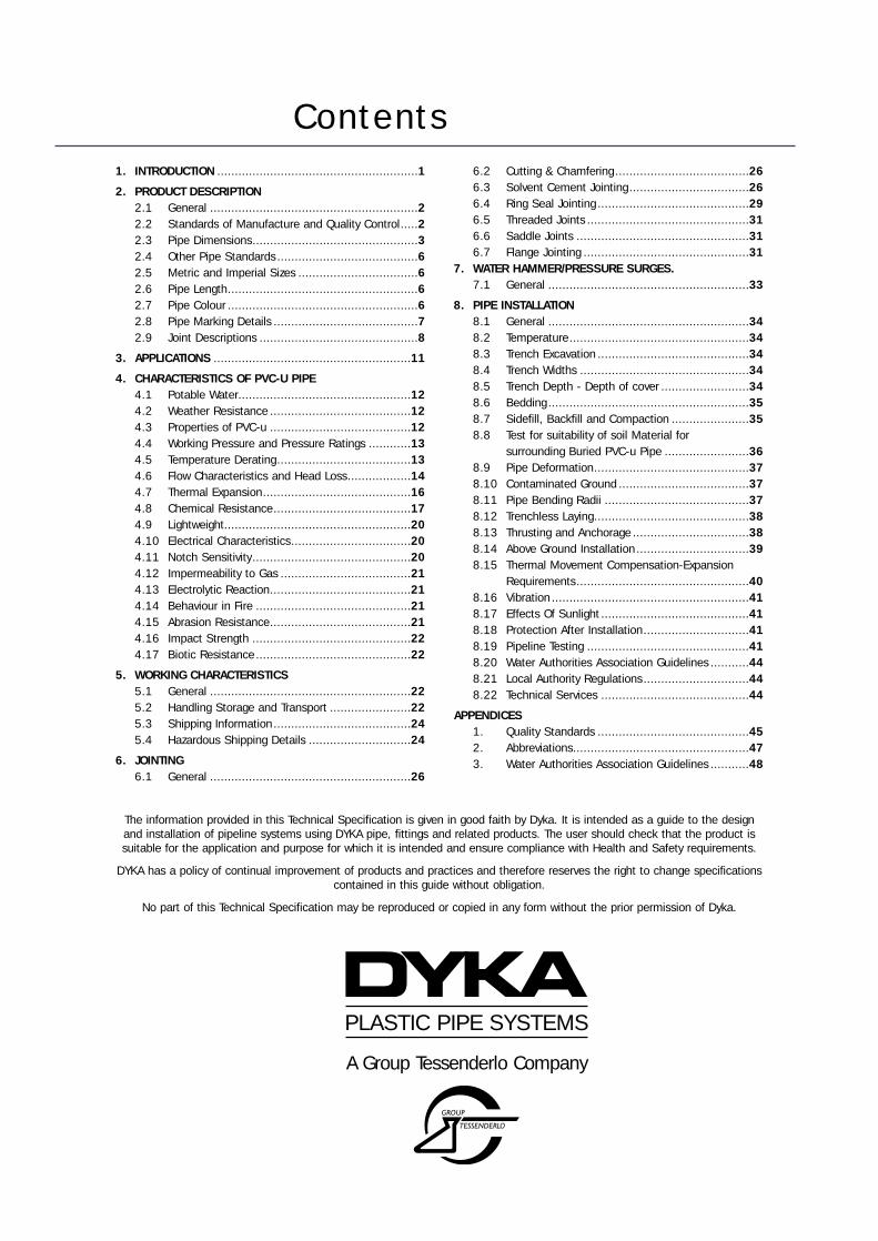
Contents1. INTRODUCTION .........................................................1
2. PRODUCT DESCRIPTION2.1 General ...........................................................22.2 Standards of Manufacture and Quality Control.....22.3 Pipe Dimensions...............................................32.4 Other Pipe Standards........................................62.5 Metric and Imperial Sizes ..................................62.6 Pipe Length......................................................62.7 Pipe Colour ......................................................62.8 Pipe Marking Details .........................................72.9 Joint Descriptions .............................................8
3. APPLICATIONS ........................................................11
4. CHARACTERISTICS OF PVC-U PIPE4.1 Potable Water.................................................124.2 Weather Resistance ........................................124.3 Properties of PVC-u ........................................124.4 Working Pressure and Pressure Ratings ............134.5 Temperature Derating......................................134.6 Flow Characteristics and Head Loss..................144.7 Thermal Expansion..........................................164.8 Chemical Resistance.......................................174.9 Lightweight.....................................................204.10 Electrical Characteristics..................................204.11 Notch Sensitivity.............................................204.12 Impermeability to Gas .....................................214.13 Electrolytic Reaction........................................214.14 Behaviour in Fire ............................................214.15 Abrasion Resistance........................................214.16 Impact Strength .............................................224.17 Biotic Resistance ............................................22
5. WORKING CHARACTERISTICS5.1 General .........................................................225.2 Handling Storage and Transport .......................225.3 Shipping Information.......................................245.4 Hazardous Shipping Details .............................24
6. JOINTING6.1 General .........................................................26
6.2 Cutting & Chamfering......................................266.3 Solvent Cement Jointing..................................266.4 Ring Seal Jointing ...........................................296.5 Threaded Joints ..............................................316.6 Saddle Joints .................................................316.7 Flange Jointing ...............................................31
7. WATER HAMMER/PRESSURE SURGES.7.1 General .........................................................33
8. PIPE INSTALLATION8.1 General .........................................................348.2 Temperature...................................................348.3 Trench Excavation ...........................................348.4 Trench Widths ................................................348.5 Trench Depth - Depth of cover .........................348.6 Bedding .........................................................358.7 Sidefill, Backfill and Compaction ......................358.8 Test for suitability of soil Material for
surrounding Buried PVC-u Pipe ........................368.9 Pipe Deformation............................................378.10 Contaminated Ground .....................................378.11 Pipe Bending Radii .........................................378.12 Trenchless Laying............................................388.13 Thrusting and Anchorage .................................388.14 Above Ground Installation................................398.15 Thermal Movement Compensation-Expansion
Requirements.................................................408.16 Vibration ........................................................418.17 Effects Of Sunlight ..........................................418.18 Protection After Installation..............................418.19 Pipeline Testing ..............................................418.20 Water Authorities Association Guidelines ...........448.21 Local Authority Regulations..............................448.22 Technical Services ..........................................44
APPENDICES1. Quality Standards ...........................................452. Abbreviations..................................................473. Water Authorities Association Guidelines ...........48
PLASTIC PIPE SYSTEMS
A Group Tessenderlo Company
The information provided in this Technical Specification is given in good faith by Dyka. It is intended as a guide to the designand installation of pipeline systems using DYKA pipe, fittings and related products. The user should check that the product issuitable for the application and purpose for which it is intended and ensure compliance with Health and Safety requirements.
DYKA has a policy of continual improvement of products and practices and therefore reserves the right to change specificationscontained in this guide without obligation.
No part of this Technical Specification may be reproduced or copied in any form without the prior permission of Dyka.
1
1. IntroductionDyka have produced this PVC-u Technical Publication to assist engineers, pipelineoperators and contractors in the design and installation of pressure pipelines. Webelieve this manual contains the best technical information available and accordingto our knowledge and research itis correct in all details. Allinformation is provided in goodfaith and entirely withoutprejudice to Dyka.
The use of unplasticisedpolyvinylchloride (PVC-u) is firmlyestablished as the preferredmaterial for pressure pipelinesand water supply installations. Itsmany advantages over traditionalmaterials have resulted in these being progressively substituted by PVC-u pipelines.
Dyka are a leading manufacturer of plastic pipe systems and have pioneered many ofthe developments in production technology. This continuing development togetherwith the introduction of the latest techniques and equipment ensures that Dyka
products are produced to ahigh standard in excess of theexacting requirements ofmany European qualityassurance organisations,including the BSI. Strictquality control through allstages of production ismaintained by Dyka’s inhouse, BSI monitoredlaboratory. The productionfacility is certified toISO9002/BS5750 (2).
Dyka hold BSI kitemark licences and other approvals in relevant to the many productsmanufactured.
Dyka are part of a European manufacturing group owned by Limburgse VinylMaatschapij NV (LVM), one of Europe’s largest PVC polymerproducers. This provides Dyka with a guaranteed supply ofthe principle raw material at a competitive price.
LVM are owned by the Belgium based multi-nationalcompany Tessenderlo Chemie NV.
2
2. Product Description2.1 GeneralPlastics are synthetic macromolecular materials which, by processing acquire theirspecific functions. They are produced by chemical processes, the principle rawmaterial being oil. The macromolecular structure of plastics is achieved bypolymerisation of individual molecules or monomers into chain molecules that arebetween 1,000 and 100,000 times larger than those naturally occurring in water orsalt. This macro molecular composition forms a spatial net-like structure withnumerous internal chemical bonds.
Plastics can be divided into two main groups.
• Thermoplastic materials which, upon heating, soften and melt and can be reheatedand reformed.
• Thermosetting materials which soften and melt with the initial heating but then setpermanently in their final shape.
Polyvinylchloride or PVC-u is one of the most widely used thermoplastic materials, dueto its flexibility of usage and competitive price. It is manufactured by thepetrochemical industry who produce a dichloride from ethane and chloride and applypyrolisis above 400ºC to cause splitting into vinylchloride and hydrochloric acid.
The basic polymer is mixed with additives such as colour, filler, lubricants andstabilisers in accordance with a recipe determined by the properties of the finishedproduct. The mix of compound is transported to either extruders or injection mouldingmachines to be converted into the end product.
Dyka PVC-u pipe is a high quality pipe suitable for pressure pipeline systems for coldwater services. It is available in imperial and metric dimensions that are produced inaccordance with appropriate national and international standards.
Dyka PVC-u pipe is supplied plain ended, with integral solvent weld socket or integralring seal joint. Refer to section 6 of this catalogue for further jointing details.
2.2 Standards of Manufacture and Quality ControlDyka produce PVC-u pressure pipe in accordance with all the principal Europeanquality standards.
All Dyka manufacturing facilities are accredited to either ISO 9001 or 9002 (EN29001/2 1987, BS5750 Parts 1 and 2). This defines the quality management systemunder which the manufacturing and support departments operate. It provides theoverall framework within which production of pipes to a particular specification, suchas BS 3505, can take place.
Dyka manufactured PVC-u products are specifically certified against the requirementsof:
WRC UKKIWA NV HollandDS DenmarkDVGW GermanySMG GermanyDIN GermanySECO FranceSee Appendix 1 for full list of standards applicable to Dyka PVC-u pressure pipe.
3
Product Description2.2.1 Production StandardsAll imperial pressure pipe within the Dyka pipe system is manufactured in accordancewith the requirements of BS 3505 specification for “Unplasticised PVC pipe for coldwater services” 1986 - as amended.
Dyka are permitted to affix the British Standards Institute “Kitemark” to theseproducts under B.S.I. Licence numbers 8017 and 8018.
Where specified Dyka, blue metric pipework is manufactured in accordance with therequirements of the water industry specification WIS 4.31.06.
Unless otherwise specified, all Dyka, standard metric pipework is manufactured to theDutch water industry standard KIWA 49 (revision 1). Dykapipe is certified to thisstandard by the KIWA quality organisation.
Dyka have the capability to manufacture to a number of the European standards andin many cases hold quality approvals against these. Details of these and copies of allcertificates are available on request.
2.2.2 Quality ControlAll quality control testing for conformity with the various production standards iscarried out by the Dyka in house laboratory. All laboratory operations are monitoredby the British Standards Institute, The Dutch KIWA Quality Organisation and others.
2.3 Pipe Dimensions
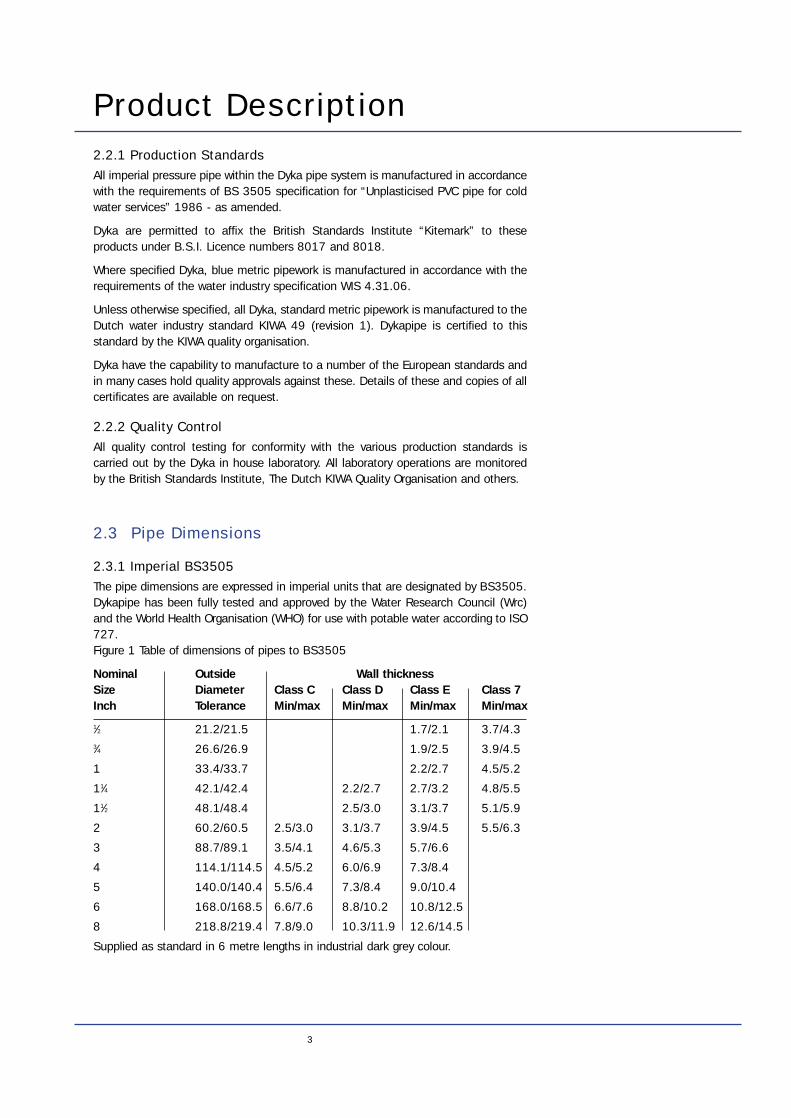
2.3.1 Imperial BS3505The pipe dimensions are expressed in imperial units that are designated by BS3505.Dykapipe has been fully tested and approved by the Water Research Council (Wrc)and the World Health Organisation (WHO) for use with potable water according to ISO727.Figure 1 Table of dimensions of pipes to BS3505
Nominal Outside Wall thicknessSize Diameter Class C Class D Class E Class 7Inch Tolerance Min/max Min/max Min/max Min/max
1⁄2 21.2/21.5 1.7/2.1 3.7/4.33⁄4 26.6/26.9 1.9/2.5 3.9/4.5
1 33.4/33.7 2.2/2.7 4.5/5.2
11⁄4 42.1/42.4 2.2/2.7 2.7/3.2 4.8/5.5
11⁄2 48.1/48.4 2.5/3.0 3.1/3.7 5.1/5.9
2 60.2/60.5 2.5/3.0 3.1/3.7 3.9/4.5 5.5/6.3
3 88.7/89.1 3.5/4.1 4.6/5.3 5.7/6.6
4 114.1/114.5 4.5/5.2 6.0/6.9 7.3/8.4
5 140.0/140.4 5.5/6.4 7.3/8.4 9.0/10.4
6 168.0/168.5 6.6/7.6 8.8/10.2 10.8/12.5
8 218.8/219.4 7.8/9.0 10.3/11.9 12.6/14.5
Supplied as standard in 6 metre lengths in industrial dark grey colour.
4
Product Description
Outside OutsideDiameter DiameterSize mm Tolerance 6.3 bar 7.5 bar 10 bar 12.5 bar 16 bar
16 16.0/16.2 1.5/1.9 1.5/1.9
20 20.0/20.2 1.5/1.9 1.5/1.9 1.5/1.9
25 25.0/25.2 1.5/1.9 1.5/1.9 1.9/2.3
32 32.0/32.2 1.6/2.0 2.4/2.9 3.0/3.5
40 40.0/40.2 1.9/2.3 2.4/2.9 3.0/3.5
50 50.0/50.2 1.6/2.0 2.0/2.4 2.4/2.9 3.0/3.5 3.7/4.3
63 63.0/63.2 2.0/2.4 2.0/2.4 2.4/2.9 3.0/3.5 3.8/4.4
75 75.0/75.3 2.0/2.4 2.2/2.7 2.9/3.4 3.6/4.2 4.5/5.2
90 90.0/90.3 2.2/2.7 2.7/3.2 3.5/4.1 4.3/5.0 5.4/6.2
110 110.0/110.4 2.7/3.2 3.2/3.8 4.2/4.9 5.3/6.1 6.6/7.5
125 125.0/125.4 3.1/3.7 3.7/4.3 4.8/5.5 6.0/6.8 7.4/8.4
160 160.0/160.5 4.0/4.6 4.7/5.4 6.2/7.1 7.7/8.7 9.5/10.7
200 200.0/200.6 4.9/5.6 5.9/6.7 7.7/8.7 9.6/10.8 11.9/13.3
250 250.0/250.8 6.2/7.1 7.3/8.3 9.6/10.8 11.9/13.3 14.8/16.5
315 315.0/316.0 7.7/8.7 9.2/10.4 12.1/13.6 15.0/16.7 18.7/20.8
400 400.0/401.0 9.8/11.0 11.7/13.1 15.3/17.1 19.1/21.3 23.7/26.3
500 500.0/501.0 12.3/13.8 14.6/16.3 19.1/21.3 23.9/26.5 29.6/32.8
630 630.0/631.0 15.4/17.2 18.4/20.5 24.1/26.8
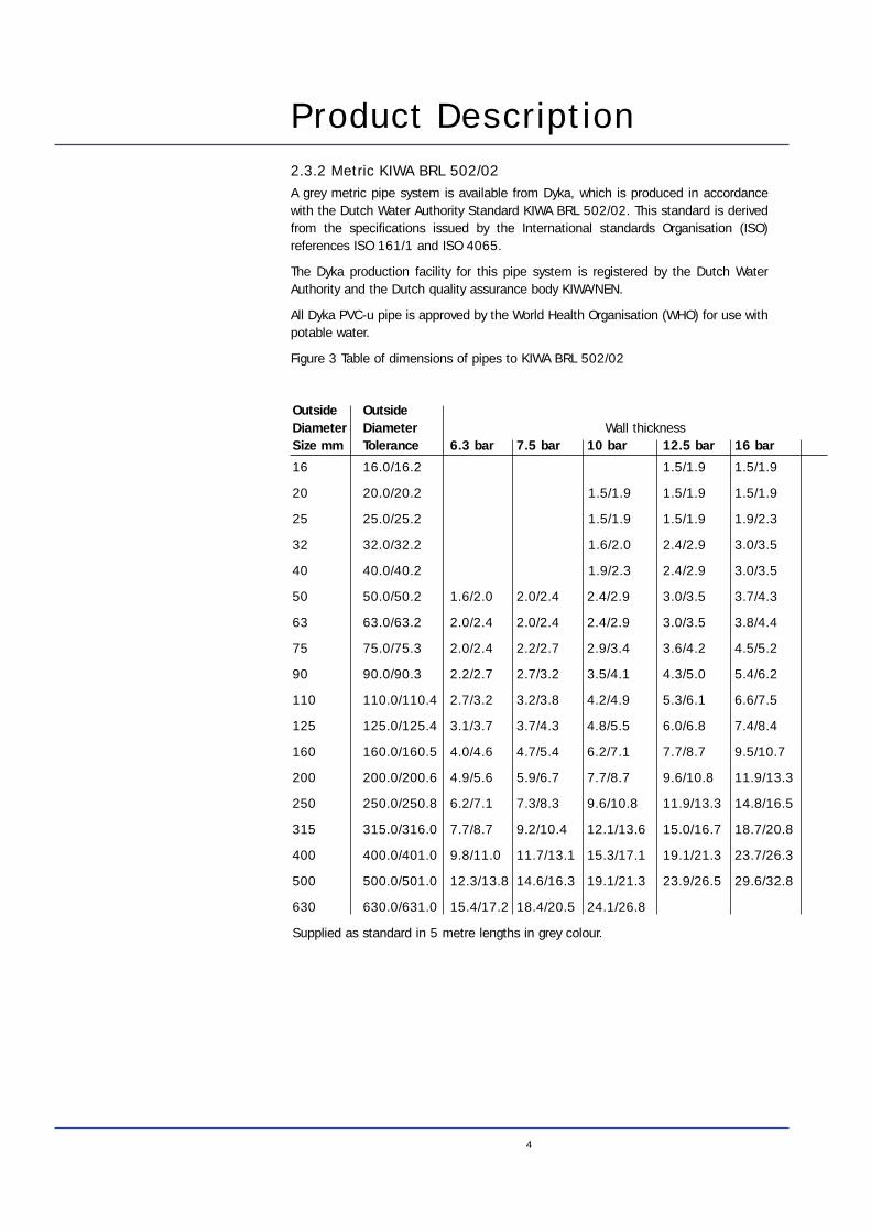
Supplied as standard in 5 metre lengths in grey colour.
Wall thickness
2.3.2 Metric KIWA BRL 502/02A grey metric pipe system is available from Dyka, which is produced in accordancewith the Dutch Water Authority Standard KIWA BRL 502/02. This standard is derivedfrom the specifications issued by the International standards Organisation (ISO)references ISO 161/1 and ISO 4065.
The Dyka production facility for this pipe system is registered by the Dutch WaterAuthority and the Dutch quality assurance body KIWA/NEN.
All Dyka PVC-u pipe is approved by the World Health Organisation (WHO) for use withpotable water.
Figure 3 Table of dimensions of pipes to KIWA BRL 502/02
5
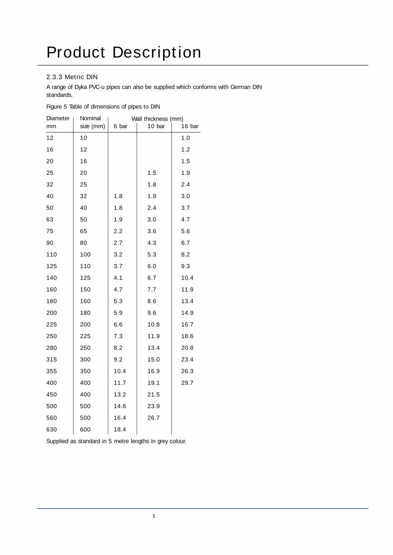
Product Description2.3.3 Metric DINA range of Dyka PVC-u pipes can also be supplied which conforms with German DINstandards.
Figure 5 Table of dimensions of pipes to DIN
Diameter Nominal mm size (mm) 6 bar 10 bar 16 bar
12 10 1.0
16 12 1.2
20 16 1.5
25 20 1.5 1.9
32 25 1.8 2.4
40 32 1.8 1.9 3.0
50 40 1.8 2.4 3.7
63 50 1.9 3.0 4.7
75 65 2.2 3.6 5.6
90 80 2.7 4.3 6.7
110 100 3.2 5.3 8.2
125 110 3.7 6.0 9.3
140 125 4.1 6.7 10.4
160 150 4.7 7.7 11.9
180 160 5.3 8.6 13.4
200 180 5.9 9.6 14.9
225 200 6.6 10.8 16.7
250 225 7.3 11.9 18.6
280 250 8.2 13.4 20.8
315 300 9.2 15.0 23.4
355 350 10.4 16.9 26.3
400 400 11.7 19.1 29.7
450 400 13.2 21.5
500 500 14.6 23.9
560 500 16.4 26.7
630 600 18.4
Supplied as standard in 5 metre lengths in grey colour.
Wall thickness (mm)
Product Description2.4 Other Pipe StandardsIn addition to the above Dyka will manufacture pipe to most European nationalstandards on specific request. Please refer to the technical department of Dyka fordetails.
Copies of all quality standards mentioned are available on application to Dyka.
2.5 Metric and Imperial SizesIt is important to note that metric and imperial pipework are two distinct systems, theyare not manufactured to compatible dimensions and cannot be interconnectedwithout special adaptors.
Dyka manufacture and supply metric to imperial adaptor couplings for both solventcement and ring seal jointing.
2.6 Pipe LengthImperial dimension pressure pipes and metric pipes to WIS 4.31.06 are supplied asstandard in nominal lengths of 6 metres. All other metric dimension pipes aresupplied in standard nominal lengths of 5 metres.
The nominal pipe length is not the working length, as this depends on the jointingmethod being employed.
Special lengths can be supplied to specific order providing the quantity constitutes areasonable production run. Contact your distributor or the technical department ofDyka for further information.
2.7 Pipe ColourAll Dyka imperial and metric pressure pipes, with the exception of those in accordancewith WIS 4.31.06 are manufactured in industrial grey (colour reference RAL 7011).
WIS 4.31.06 pipework is blue colour coded for potable water (colour referenceBS4901: 20 E54).
Metric pipes to KIWA 49 can be supplied in natural PVC-u, cream colour.
Pipework in other colours can be produced against specific requirements providing thequantity constitutes a reasonable production run. Contact your distributor or thetechnical department of Dyka for further information.
6
7
Product Description2.8 Pipe Marking DetailsThe precise marking of Dyka PVC-u pipe is governed by various national andinternational standards, although to ensure traceability of pipes supplied the followinginformation is usually included:
2.8.1 Imperial pipe markingDescription Example
Manufacturers identification: DYKAPipe material: PVC-uThe British Standard: BS3505:1986/BS4346 (mechanically jointed pipes)
Pressure rating: 12 barSize and dimensions: 3"x04.6mmProduction code: 2088 5757Fracture toughness: 3.75 n/mm2
The markings for different classes of pipe are colour coded as below and embossedinto the pipe wall to avoid accidental erasure.
Class C D EColour Black Green Brown
2.8.2 Metric pipe marking
Metric pipe to WIS 4.31.06 (markings in white colour)
Description Example
Water industry specification: WIS 4.31.06Manufacturers identification: DYKANominal outside diameter: 200mmPipe material: PVC-uNominal pressure: 12.5 barProduction code: 21 88 23 7 B
Other metric pipe (markings in black colour)
Description Example
Manufacturers identification: DYKAProduction standard: KIWAPressure rating: 1.25 MPADimensions: 63 x 3.0mmProduction code: 21 88 23 7 B
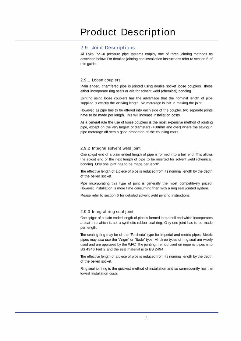
Product Description2.9 Joint DescriptionsAll Dyka PVC-u pressure pipe systems employ one of three jointing methods asdescribed below. For detailed jointing and installation instructions refer to section 6 ofthis guide.
2.9.1 Loose couplersPlain ended, chamfered pipe is jointed using double socket loose couplers. Theseeither incorporate ring seals or are for solvent weld (chemical) bonding.
Jointing using loose couplers has the advantage that the nominal length of pipesupplied is exactly the working length. No meterage is lost in making the joint.
However, as pipe has to be offered into each side of the coupler, two separate jointshave to be made per length. This will increase installation costs.
As a general rule the use of loose couplers is the most expensive method of jointingpipe, except on the very largest of diameters (400mm and over) where the saving inpipe meterage off-sets a good proportion of the coupling costs.
2.9.2 Integral solvent weld jointOne spigot end of a plain ended length of pipe is formed into a bell end. This allowsthe spigot end of the next length of pipe to be inserted for solvent weld (chemical)bonding. Only one joint has to be made per length.
The effective length of a piece of pipe is reduced from its nominal length by the depthof the belled socket.
Pipe incorporating this type of joint is generally the most competitively priced.However, installation is more time consuming than with a ring seal jointed system.
Please refer to section 6 for detailed solvent weld jointing instructions.
2.9.3 Integral ring seal jointOne spigot of a plain ended length of pipe is formed into a bell end which incorporatesa seat into which is set a synthetic rubber seal ring. Only one joint has to be madeper length.
The sealing ring may be of the "Forsheda" type for imperial and metric pipes. Metricpipes may also use the "Anger" or "Bode" type. All three types of ring seal are widelyused and are approved by the WRC. The jointing method used on imperial pipes is toBS 4346 Part 2 and the seal material is to BS 2494.
The effective length of a piece of pipe is reduced from its nominal length by the depthof the belled socket.
Ring seal jointing is the quickest method of installation and so consequently has thelowest installation costs.
8
9
Product Description
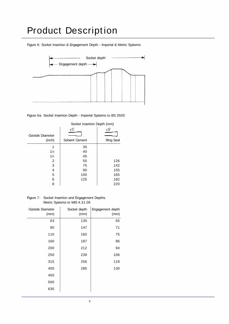
Outside Diameter(inch) Solvent Cement Ring Seal
1 3511⁄4 4011⁄2 45
2 55 1263 75 1424 90 1555 100 1656 125 1828 220
Figure 6: Socket Insertion & Engagement Depth - Imperial & Metric Systems
Socket insertion Depth (mm)
Outside Diameter Socket depth Engagement depth(mm) (mm) (mm)
63 130 65
90 147 71
110 160 75
160 187 86
200 212 94
250 239 106
315 256 118
400 285 130
450
500
630
Figure 7: Socket Insertion and Engagement Depths.Metric Systems to WIS 4.31.06
Figure 6a: Socket Insertion Depth - Imperial Systems to BS 3505
Engagement depth
Socket depth
Product Description
10
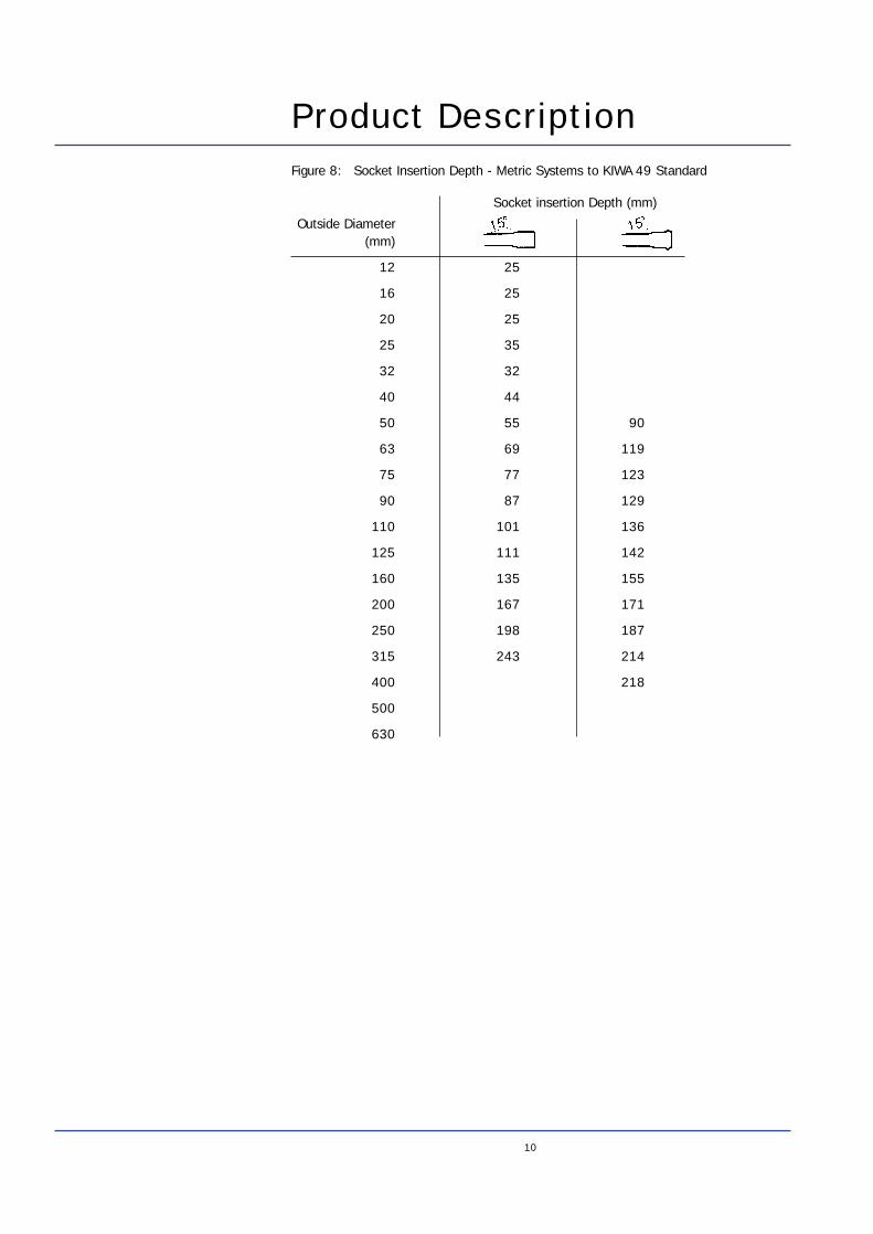
Outside Diameter(mm)
12 25
16 25
20 25
25 35
32 32
40 44
50 55 90
63 69 119
75 77 123
90 87 129
110 101 136
125 111 142
160 135 155
200 167 171
250 198 187
315 243 214
400 218
500
630
Socket insertion Depth (mm)
Figure 8: Socket Insertion Depth - Metric Systems to KIWA 49 Standard
11
3. ApplicationsThe Dykapipe PVC-u pressure pipe system is suitable for the transportation of potablewater for industrial and domestic uses. Other major areas of application include:-
Agricultural irrigation
Conveyance of processing fluids within industry
Sewerage and industrial effluent disposal
Conveyance of abrasive slurries
Transportation of acids, alkalis and other corrosive chemicals (refer to section 4.8)
Ground water transportation for land engineering
Buried fire ringmain
Conduit or duct for cables and fragile piping systems
Venting systems
Rigid PVC-u Dykapipe should not be used at ambient or liquid temperatures in excessof 60°C for pressure systems.
For other applications, please refer to the technical department of Dyka
4.1 Potable WaterDykapipe is manufactured to meet all of the requirements of BS 6920, BS 3505 andISO 727, making it suitable for the supply of all cold water services including potablewater. Dyka manufactured PVC-u pipe will not impart taint or taste to potable waterand has been toxicologically approved by:
The Department of the Environment - Committee on chemicals and materials ofconstruction for use in public water supply and swimming pools (DOE - CCM)
Wrc - Water byelaws advisory service
KIWA - Attest
World health organisation (WHO)
4.2 Weather ResistanceThe pipe is protected against some of the harmful effects of sunlight by the use ofopacifiers in the pipe formulation. Despite this Dykapipe should not be stored in directsunlight for periods in excess of 1 to 2 months (see section 5.2 Handling, storage andtransport).
Refer to sections 9.17 and 9.18 for details on the protection of PVC-u pipe from longexposure to sunlight.
4.3 Properties of PVC-uGeneralSpecific gravity: 1.4g/mm3Opacity: less than 0.2%Water absorption: 0.12% in 24hrs @ 23°C
MechanicalUltimate tensile strength: 50 N/mm2Compressive strength: 66 MpaImpact - DIN 53453: 5kg cm/cm notchElastic modulus in bend: 3000 MpaBrinell hardness @ 23O°C: 12 - 15Poisson’s ratio: 0.35Flexural strength: 70 - 110 MpaElongation at break @ 23O°C: 80 - 150%Fracture toughness in excess of: 3.75 n/mm2(against method C.3..1. BS 3505: 1986)
ElectricalVolume resistivity: 1050 Ohms/cm3Breakdown voltage: 30 kv/mmPower factor: 0.02 at 800 HzDielectric constant: 3.4 at 800 Hz
ThermalProcessing temperature 150O - 180O CCoefficient of thermal expansion: 0.06 mm/mkThermal conductivity: 0.16 w/mkSpecific heat: 1050OCSoftening point: 80OC(BS 2782 method 120B)Flammability: Self extinguishing
12
4. Characteristics PVC-u Pipe
13
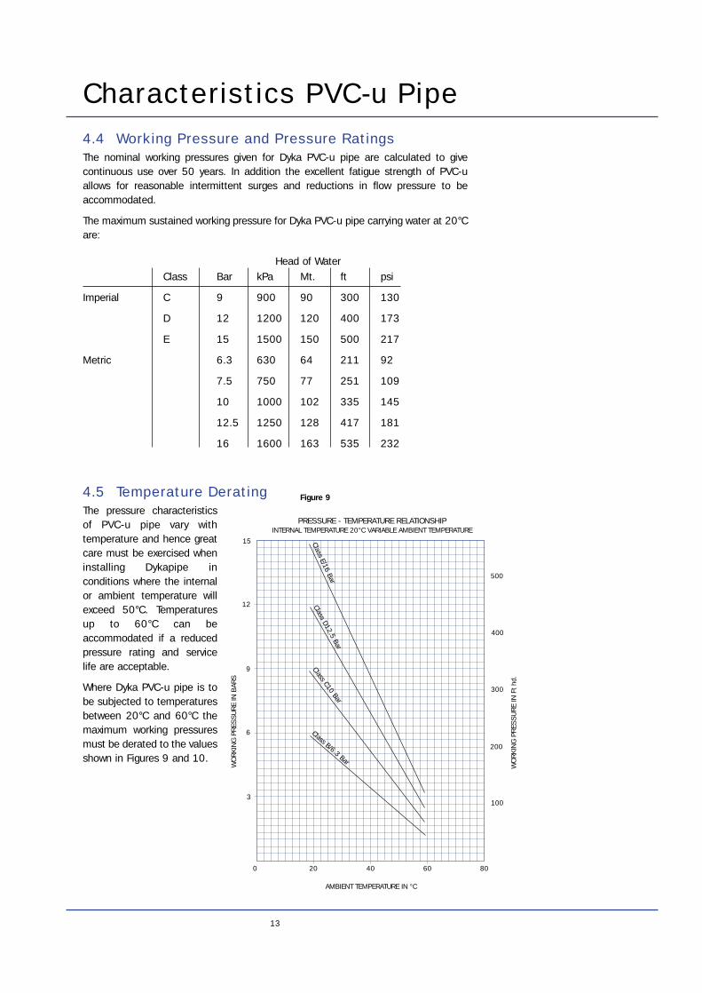
4.4 Working Pressure and Pressure RatingsThe nominal working pressures given for Dyka PVC-u pipe are calculated to givecontinuous use over 50 years. In addition the excellent fatigue strength of PVC-uallows for reasonable intermittent surges and reductions in flow pressure to beaccommodated.
The maximum sustained working pressure for Dyka PVC-u pipe carrying water at 20°Care:
Class Bar kPa Mt. ft psi
Imperial C 9 900 90 300 130
D 12 1200 120 400 173
E 15 1500 150 500 217
Metric 6.3 630 64 211 92
7.5 750 77 251 109
10 1000 102 335 145
12.5 1250 128 417 181
16 1600 163 535 232
4.5 Temperature DeratingThe pressure characteristicsof PVC-u pipe vary withtemperature and hence greatcare must be exercised wheninstalling Dykapipe inconditions where the internalor ambient temperature willexceed 50°C. Temperaturesup to 60°C can beaccommodated if a reducedpressure rating and servicelife are acceptable.
Where Dyka PVC-u pipe is tobe subjected to temperaturesbetween 20°C and 60°C themaximum working pressuresmust be derated to the valuesshown in Figures 9 and 10.
Characteristics PVC-u Pipe
Head of Water
0 20 40 60 80
3
6
9
12
15
100
200
300
400
500
Class B/6.3 Bar
Class C10 Bar
Class D12.5 Bar
Class E/16 Bar
AMBIENT TEMPERATURE IN °C
WO
RKI
NG
PR
ESS
UR
E IN
BAR
S
PRESSURE - TEMPERATURE RELATIONSHIPINTERNAL TEMPERATURE 20°C VARIABLE AMBIENT TEMPERATURE
WO
RKI
NG
PR
ESS
UR
E IN
Ft
hd.
Figure 9
14
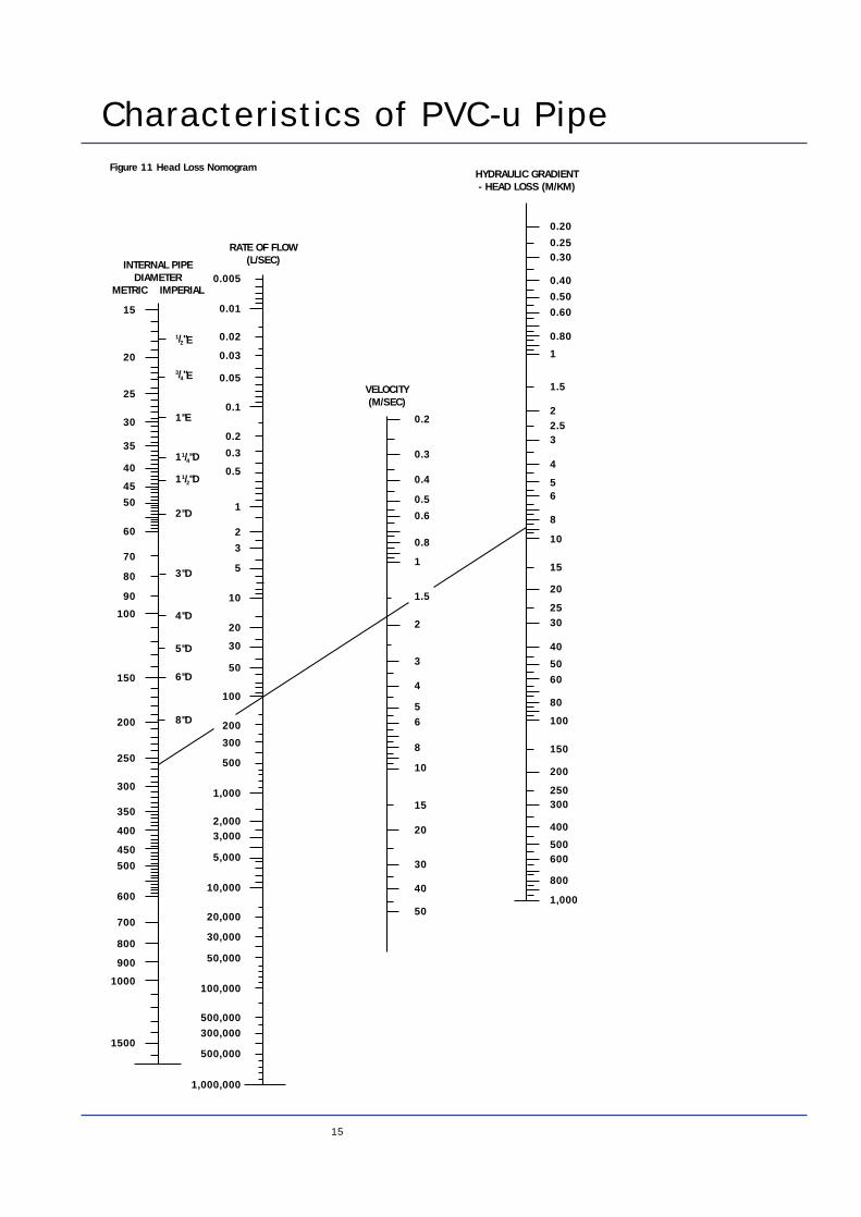
4.6 Flow Characteristics and Head LossIn any pipeline a certain amount of fluid pressure will be lost or dissipated due to theeffects of friction or disturbance of the fluid load against the internal pipe wall.
These friction or head losses can be categorised into two areas. General head lossbeing the decrease in applied pressure due to the friction of the fluid load against theinternal pipe wall and Point losses caused by the interruption of the smooth fluid flowby a fitting.
4.6.1 General Head LossThe consistently smooth bore of Dyka PVC-u pipe means that very low flow resistanceis experienced in the pipe.
In addition the long term build up of accretion on the bore of the pipe is virtually nilbecause of its smooth walls and non-corrosive nature. This alleviates the need toincrease pumping power over time as required in systems of more traditionalmaterials.
As a result of these efficient flow characteristics, economies can be achieved overtraditional materials by the use of smaller diameters to give equivalent flow rates orby greater flow rates being achieved through PVC-u pipes of the same diameter.
Any liquid will lose some pressure or head as it flows along the pipe and this must beaccommodated in the design of the pipe system. Given any two of the three variables:head loss, pipe diameter or flow rate, the third unknown variable can be determinedusing figure 11.
Characteristics PVC-u Pipe
0 20 40 60 80
3
6
9
12
15
100
200
300
400
500
Class B/6.3 Bar
INTERNAL TEMPERATURE IN °C
WO
RKI
NG
PR
ESS
UR
E IN
BAR
S
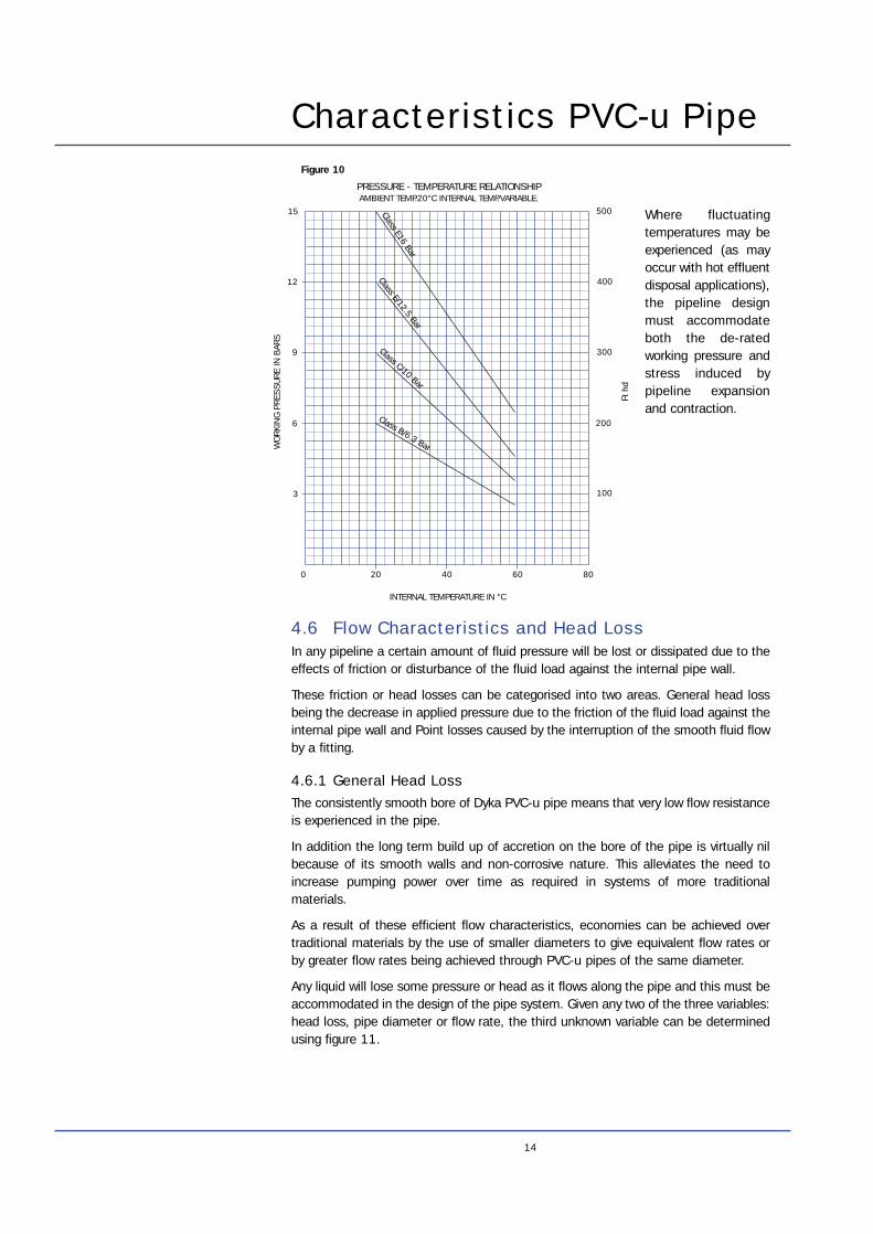
PRESSURE - TEMPERATURE RELATIONSHIPAMBIENT TEMP.20°C INTERNAL TEMP.VARIABLE.
Ft h
d
Class C/10 Bar
Class E/12.5 Bar
Class E16 Bar
Where fluctuatingtemperatures may beexperienced (as mayoccur with hot effluentdisposal applications),the pipeline designmust accommodateboth the de-ratedworking pressure andstress induced bypipeline expansionand contraction.
Figure 10
15
Characteristics of PVC-u Pipe
15
INTERNAL PIPEDIAMETER
METRIC IMPERIAL
RATE OF FLOW(L/SEC)
VELOCITY(M/SEC)
HYDRAULIC GRADIENT- HEAD LOSS (M/KM)
20
25
30
35
40
45
50
60
70
80
90
100
150
200
250
300
350
400
450
500
600
700
800
900
1000
1500
0.005
0.01
0.02
0.03
0.05
0.10.2
0.20
0.30
0.40
0.50
0.60
0.80
1
1.5
22.53
4
56
8
10
15
20
2530
40
50
60
80
100
150
200
250300
400
500600
800
1,000
0.25
0.3
0.4
0.5
0.6
0.8
1
1.5
2
3
4
56
8
10
15
20
30
40
50
0.2
0.3
0.5
1
2
3
5
10
20
30
50
100
200
300
500
1,000
2,0003,000
5,000
10,000
20,000
30,000
50,000
100,000
500,000300,000
500,000
1,000,000
1/2"E
3/4"E
1"E
11/4"D
11/2"D
2"D
3"D
4"D
5"D
6"D
8"D
Figure 11 Head Loss Nomogram
Characteristics PVC-u Pipe
16
The values given in figure 11 can be manually calculated for any given flowrequirements and internal diameter using the adapted Colebrook-White formulashown below:
Q
√SD2.5
K
3.71D= - 6.61 log +{ ()( }(5.63 x 10⁻⁶) D
Q )1.053 0.937
Where Q is the discharge rate. S is piezometric gradient.D is the internal diameter of pipe. K is pipe wall roughness factor.
Assuming that the temperature of the fluid is 20°C and that it has a density of 1g percm3. For the purposes of this calculation PVC-u pipe has a wall roughness factor (K)of 0.003 mm.
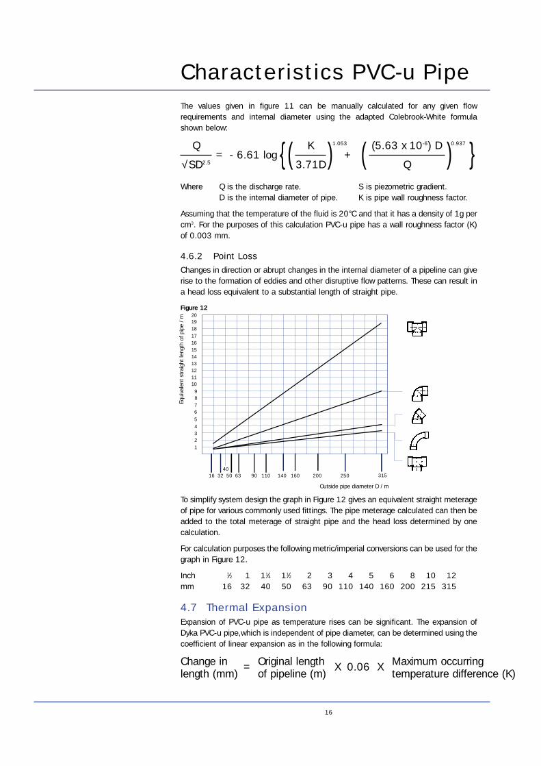
4.6.2 Point LossChanges in direction or abrupt changes in the internal diameter of a pipeline can giverise to the formation of eddies and other disruptive flow patterns. These can result ina head loss equivalent to a substantial length of straight pipe.
To simplify system design the graph in Figure 12 gives an equivalent straight meterageof pipe for various commonly used fittings. The pipe meterage calculated can then beadded to the total meterage of straight pipe and the head loss determined by onecalculation.
For calculation purposes the following metric/imperial conversions can be used for thegraph in Figure 12.
Inch 1⁄2 1 11⁄4 11⁄2 2 3 4 5 6 8 10 12mm 16 32 40 50 63 90 110 140 160 200 215 315
4.7 Thermal ExpansionExpansion of PVC-u pipe as temperature rises can be significant. The expansion ofDyka PVC-u pipe,which is independent of pipe diameter, can be determined using thecoefficient of linear expansion as in the following formula:
12345
6789
1011121314151617181920
4016 32 50 63 90 110 140 160 200
Outside pipe diameter D / m
315250
Equi
vale
nt s
trai
ght
leng
th o
f pip
e / m
Change in Original length Maximum occurring length (mm) of pipeline (m) temperature difference (K)
= X 0.06 X
Figure 12
17
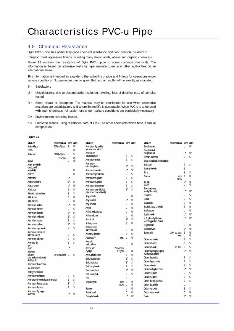
Characteristics PVC-u Pipe4.8 Chemical ResistanceDyka PVC-u pipe has particularly good chemical resistance and can therefore be used to
transport most aggressive liquids including many strong acids, alkalis and organic chemicals.
Figure 13 outlines the resistance of Dyka PVC-u pipe to some common chemicals. Theinformation is based on extensive tests by pipe manufacturers and other authorities on aninternational basis.
This information is intended as a guide to the suitability of pipe and fittings for operations undervarious conditions. No guarantee can be given that actual results will be exactly as indicated.
S = Satisfactory
U = Unsatisfactory, due to decomposition, solution, swelling, loss of ductility, etc., of samplestested.
D = Some attack or absorption. The material may be considered for use when alternativematerials are unsatisfactory and where limited life is acceptable. When PVC-u is to be usedwith such chemicals, full scale trials under realistic conditions are particularly necessary.
E = Environmental stressing hazard.
* = Predicted results, using resistance data of PVC-u to other chemicals which have a similarcomposition.
Acetaldehyde 40%(w/v)soln. S U* 100% U UAcetic acid 10%(v/v)soln. S S
60%(v/v) S Dglacial U UAcetic anhydride (acetic acid anhydride) U UAcetone U UAcetonitrile U*Acetophenetidine S* S*Acetophenone U* U*Adipic acid S DAliphatic hydrocarbons S SAllyl alcohol D UAllyl chloride U UAluminium acetate S* S*Aluminium chloride S SAluminium fluoride S* S*Aluminium hydroxide S* S*Aluminium nitrate S SAluminium oxalate S* S*Aluminium oxychloride S SAluminium potassium sulphate (alum) S SAluminium sulphate S SAmmonia dry S Sgas Uliquid U*Ammonia solution 35%(m/v)soln S S(ammonium hydroxide)(0.88g/ml)Ammonium bicarbonate see ammonium hydrogen carbonateAmmonium carbonate S SAmmonium chloride(liquid ammonia) S SAmmonium ferrous citrate S* S*Ammonium flouride S SAmmonium hydrogen carbonate S* S*
Ammonium hydroxide, see ammonia solutionAmmonium metaphosphate S SAmmonium nitrate S SAmmonium orthophosphates S* S*Ammonium oxalate S* S*Ammonium persulphate S SAmmonium sulphate S SAmmonium sulphide S SAmmonium thiocyanate S SAmmonium zinc chloride S* S*(zinc ammonium chloride)Amyl acetate U UAmyl alcohol S* UAmyl chloride U UAniline U UAniline hydrochloride U UAniline sulphate U UAnimal oils S* S*Anthraquinone S UAnthraquinone sulphonic acid S UAntimony chloride S S*Aqua regia** conc. U UAromatic hydrocarbons U UArsenic acid 75%(m/m) (syrupy) or 2g/ml S DAryl sulphonic acids S UBarium carbonate S* S*Barium chloride S* S*Barium hydroxide S SBarium sulphate S* S*Barium sulphide S SBeer SBenzaldehyde trace U U
100% U UBenzene U UBenzoic acid D UBenzoyl chloride U* U*
Benzyl acetate U U*Benzyl alcohol phenylcarbinol U* U*Bismuth carbonate S SBorax, see disodium tetraborateBoric acid S SBoron trifluoride SBrine S SBromine trace S U
100% dry gas U* ULiquid U UBromomethane (methyl bromide) U* U*Butadiene S SButane S SButanediols U UButanols (butyl alcohols) S DButyl acetate U UButyl chloride U* U*isoButyl methyl ketone U* U*(4-methylpentan-2-one)Butylphenols U UButyraldehyde U* U*Butyric acid 20% aq. soln. S U*
conc. U UCalcium carbonate S SCalcium chlorate S SCalcium chloride aq. soln. S SCalcium hydrogen sulphite S* S*(calcium bisulphite)Calcium hydroxide S SCalcium hypochlorite S SCalcium nitrate S SCalcium orthophosphates S* S*Calcium sulphate S SCalcium sulphide S SCarbon dioxide, gaseous S SCarbon disulphide UCarbon monoxide S SCarbon tetrachloride D UCasein S* S*
Medium Concentration 20°C 60°C Medium Concentration 20°C 60°C Medium Concentration 20°C 60°C
Figure 13
18
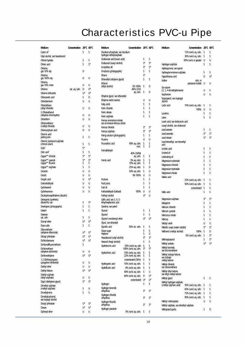
Characteristics PVC-u Pipe
Castor oil˝ S SCetyl alcohol, see hexadecanolChloral hydrate S SChloric acid S S*Chlorine, gas 10% dry DChlorine, gas 100% dry D UChlorine, gas 10% moist U UChlorine sat. aq. soln. D U*Chlorine trifluoride U* U*Chloroacetic acid S DChlorobenzene U UChloroethane (ethyl chloride) U U2-Chloroethanol (ethylene chlorohydrin) U UChloroform U UChloromethane (methyl chloride) U UChlorosulphuric acid D UChromic acidplating soln. S SChromic potassium sulphate (chrome alum) S SCider˝ S*Citric acid˝ S SCopper** chloride S* S*Copper** cyanide S* S*Copper** flouride S SCopper** sulphate S SCreosote U UCresols U UCresylic acid U U*Crotonaldehyde U UCyclohexanol U UCyclehexanone U UDecahydronaphthalene (decalin)Detergents (synthetic)diluted for use S S*Developers (photographic) S SDextrin S SDextrosesat. soln. S SDiamyl ether U* U*Diazo salts S SDibromethane (ethylene dibromide) U* U*Dibutyl phthalate U* U*Dichlorobenzene U* U*Dichlorodifluoromethane SDichloroethane (ethylene dichloride) U UDichloroethylene U* U*1.2-Dichloropropane (propylene dichloride) U UDiethyl ether U UDiethyl Ketone U* U*Diethyl sulphate (ethyl sulphate) U UDigol (diethylene glycol) S* S*Dimethyl sulphate (methyl sulphate) S UDimethylmine S SDimethylcarboinol, see isoprpyl alcoholDioctyl phthalate U* U*Dioxan U* U*Diphenyl ether U U
Disodium phosphate, see disodium hydrogen orthophosphateDodecanoic acid (lauric acid) S SDodecanol (lauryl alcohol) S* S*Emulsifiers All S* S*Emulsions (photographic) S SEthane S*Ethanediol (ethylene glycol) S SEthanol (ethyl alcohol) 95-100% S D
40% (V/V) aq. soln. S D
Ethylene glycol, see ethanediolEthylene oxide (oxiran) U UFatty acids S SFerric chloride S SFerric nitrate S SFerric sulphate S SFerrous ammonium citrate, see ammonium ferrous citrateFerrous chloride S* S*Ferrous sulphate S* S*Fixing solution (photographic) S SFluorine U UFlourosilicic acid 40% aq. soln. S S
conc. S SFormaldehyde
40% (W/W) aq. soln. S S
Formic acid 3% aq. soln. S S10% aq. soln. S S25% aq. soln. S D50% aq. soln. S U
98-100% U UFructose S SFruit juices S SFuel oil S SFurfuraldehyde (furfural) 100% U UFurfuryl alcohol U* UGallic acid, see 3, 4, 5-trihydroxybenzoic acidGasoline, see petrolGlucose S SGlycerol S SGlycerol monobenzyl ether U* U*Glycol, see ethandiolGlycollic acid 30% alc. soln. S SGrape sugar S SHeptane S UHexadecanol (cetyl alcohol) S* S*Hexanol (hexyl alcohol) S SHydrobromic acid 50% (w/v) aq. soln S S
100% (w/v) aq. soln. S* S*Hydrochloric acid 10% (w/v) aq. soln. S S
22% (w/v) aq. soln. S Sconcentrated (36%) S S
Hydrocyanic acid 10% (w/v) aq. soln. S SHydrofluoric acid 4% (w/v) aq. soln. S S
40% (w/v) aq. soln. S U60% (w/v) aq. soln. D U*
concentrated U* U*Hydrogen S SHydrogen bromideanhydrous S* S*Hydrogen chlorideanhydrous S* S*Hydrogen flourideanhydrous S* S*Hydrogen peroxide
3% (w/v) aq. soln. S S
12% (w/v) aq. soln. S S30% (w/v) aq. soln. S S
90% (w/v) or greater U UHydrogen sulphide S SHydroquinone, see quinolHydroxylammonium sulphate S SHypochlorous acid D U*Iodine soln. in
potassium iodide U UIso-octane (2, 2, 4-trimethylbentane) U SIsophorone U UIsopropanol, see isopropyl alcoholLactic acid 10% (w/v) aq. soln. S S
100% U ULanoline S SLatex S SLauric acid, see dodecanoic acidLauryl alcohol, see dodecanolLead acetate S SLead arsenate S* S*Lead nitrate S* S*Lead tetraethyl, see tetraethyl acidLinoleic acid S SLinseed oil S SLubricating oil S SMagnesium carbonate S SMagnesium chloride S SMagnesium hydroxide S SMagnesium nitrate S SMaleic acid
25% (w/v) aq. soln. S S50% (w/v) aq. soln. S S
concentrated S SMalic acid S S
Magnesium sulphate S* S*Margarine S SMercuric chloride S SMercuric cyanide S SMercurous nitrate S SMercury S SMesityl oxide U UMetallic soaps (water soluble) S* S*Methanol (methyl alcohol) 100% S D
6% (w/v) aq. soln. S S*Methoxybutanol S S*Methyl acetate U* U*Methyl bromide, see bromomethaneMethyl isobutyl ketone, see isobutyl methyl ketoneMethyl chloride, see chloromethaneMethyl ethyl ketone, see ethyl methyl ketoneMethyl glycol S SMethyl hydrogen sulphate (methyl sulphuric acid) 50% (w/v) aq. soln. S S
60% (w/v) aq. soln. S S75% (w/v) aq. soln. S S90% (w/v) aq. soln. S S
Methyl methacrylate U UMethyl sulphate, see dimethyl sulphateMethylated spirits S D
Medium Concentration 20°C 60°C Medium Concentration 20°C 60°C Medium Concentration 20°C 60°C
19
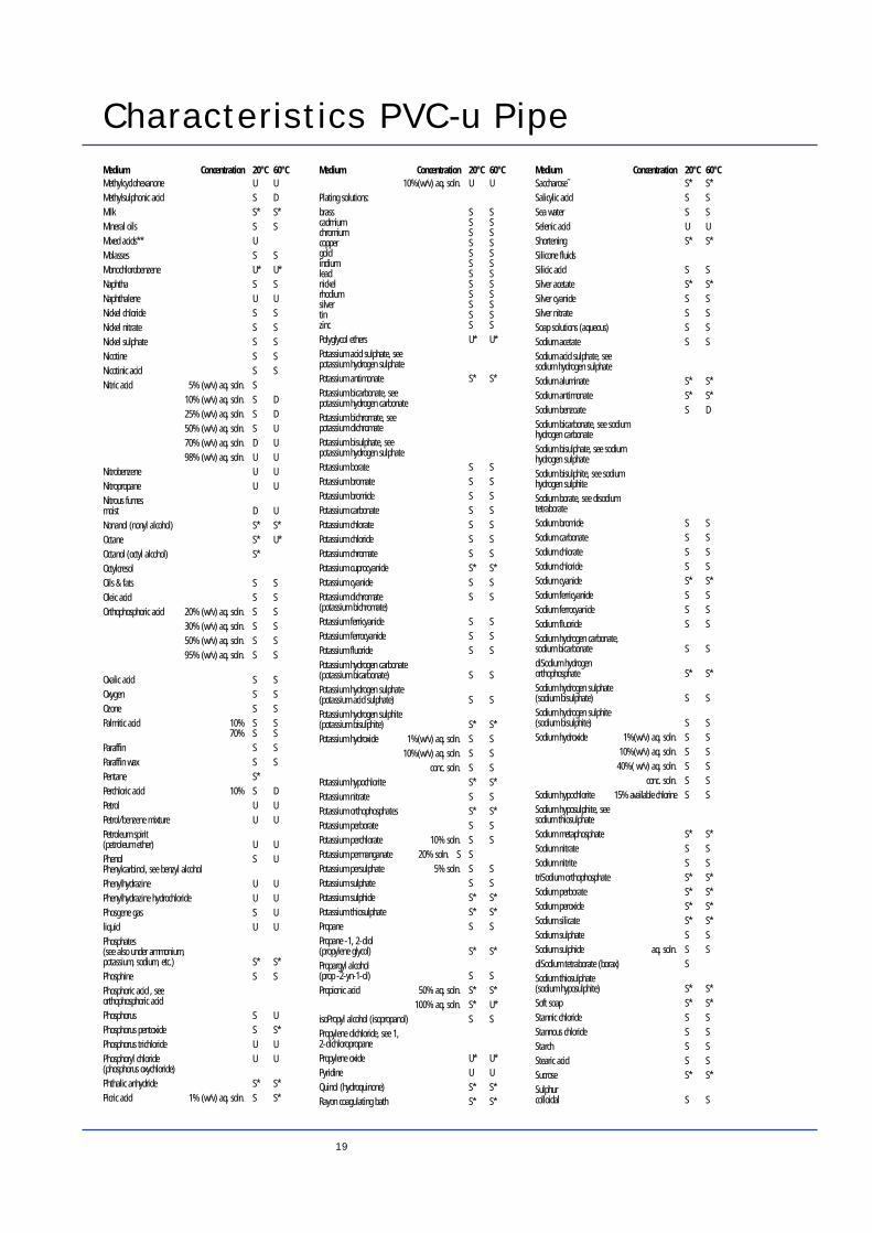
Characteristics PVC-u Pipe
Methylcyclohexanone U UMethylsulphonic acid S DMilk S* S*Mineral oils S SMixed acids** UMolasses S SMonochlorobenzene U* U*Naphtha S SNaphthalene U UNickel chloride S SNickel nitrate S SNickel sulphate S SNicotine S SNicotinic acid S SNitric acid 5% (w/v) aq. soln. S
10% (w/v) aq. soln. S D25% (w/v) aq. soln. S D50% (w/v) aq. soln. S U70% (w/v) aq. soln. D U98% (w/v) aq. soln. U U
Nitrobenzene U UNitropropane U UNitrous fumesmoist D UNonanol (nonyl alcohol) S* S*Octane S* U*Octanol (octyl alcohol) S*OctylcresolOils & fats S SOleic acid S SOrthophosphoric acid 20% (w/v) aq. soln. S S
30% (w/v) aq. soln. S S50% (w/v) aq. soln. S S95% (w/v) aq. soln. S S
Oxalic acid S SOxygen S SOzone S SPalmitic acid 10% S S
70% S SParaffin S SParaffin wax S SPentane S*Perchloric acid 10% S DPetrol U UPetrol/benzene mixture U UPetroleum spirit (petroleum ether) U UPhenol S UPhenylcarbinol, see benzyl alcoholPhenylhydrazine U UPhenylhydrazine hydrochloride U UPhosgene gas S Uliquid U UPhosphates (see also under ammonium, potassium, sodium, etc.) S* S*Phosphine S SPhosphoric acid , see orthophosphoric acidPhosphorus S UPhosphorus pentoxide S S*Phosphorus trichloride U UPhosphoryl chloride U U(phosphorus oxychloride)Phthalic anhydride S* S*Picric acid 1% (w/v) aq. soln. S S*
10%(w/v) aq. soln. U UPlating solutions:brass S Scadmium S Schromium S Scopper S Sgold S Sindium S Slead S Snickel S Srhodium S Ssilver S Stin S Szinc S SPolyglycol ethers U* U*Potassium acid sulphate, see potassium hydrogen sulphatePotassium antimonate S* S*Potassium bicarbonate, see potassium hydrogen carbonatePotassium bichromate, see potassium dichromatePotassium bisulphate, see potassium hydrogen sulphatePotassium borate S SPotassium bromate S SPotassium bromide S SPotassium carbonate S SPotassium chlorate S SPotassium chloride S SPotassium chromate S SPotassium cuprocyanide S* S*Potassium cyanide S SPotassium dichromate S S(potassium bichromate)Potassium ferricyanide S SPotassium ferrocyanide S SPotassium fluoride S SPotassium hydrogen carbonate (potassium bicarbonate) S SPotassium hydrogen sulphate (potassium acid sulphate) S SPotassium hydrogen sulphite (potassium bisulphite) S* S*Potassium hydroxide 1%(w/v) aq. soln. S S
10%(w/v) aq. soln. S Sconc. soln. S S
Potassium hypochlorite S* S*Potassium nitrate S SPotassium orthophosphates S* S*Potassium perborate S SPotassium perchlorate 10% soln. S SPotassium permanganate 20% soln. S SPotassium persulphate 5% soln. S SPotassium sulphate S SPotassium sulphide S* S*Potassium thiosulphate S* S*Propane S SPropane -1, 2-diol (propylene glycol) S* S*Propargyl alcohol (prop -2-yn-1-ol) S SPropionic acid 50% aq. soln. S* S*
100% aq. soln. S* U*isoPropyl alcohol (isopropanol) S SPropylene dichloride, see 1, 2-dichloropropanePropylene oxide U* U*Pyridine U UQuinol (hydroquinone) S* S*Rayon coagulating bath S* S*
Saccharose˝ S* S*Salicylic acid S SSea water S SSelenic acid U UShortening S* S*Silicone fluidsSilicic acid S SSilver acetate S* S*Silver cyanide S SSilver nitrate S SSoap solutions (aqueous) S SSodium acetate S SSodium acid sulphate, see sodium hydrogen sulphateSodium aluminate S* S*Sodium antimonate S* S*Sodium benzoate S DSodium bicarbonate, see sodium hydrogen carbonateSodium bisulphate, see sodium hydrogen sulphateSodium bisulphite, see sodium hydrogen sulphiteSodium borate, see disodium tetraborateSodium bromide S SSodium carbonate S SSodium chlorate S SSodium chloride S SSodium cyanide S* S*Sodium ferricyanide S SSodium ferrocyanide S SSodium fluoride S SSodium hydrogen carbonate, sodium bicarbonate S SdiSodium hydrogen orthophosphate S* S*Sodium hydrogen sulphate (sodium bisulphate) S SSodium hydrogen sulphite(sodium bisulphite) S SSodium hydroxide 1%(w/v) aq. soln. S S
10%(w/v) aq. soln. S S40%( w/v) aq. soln. S S
conc. soln. S SSodium hypochlorite 15% available chlorine S SSodium hyposulphite, see sodium thiosulphateSodium metaphosphate S* S*Sodium nitrate S SSodium nitrite S StriSodium orthophosphate S* S*Sodium perborate S* S*Sodium peroxide S* S*Sodium silicate S* S*Sodium sulphate S SSodium sulphide aq. soln. S SdiSodium tetraborate (borax) SSodium thiosulphate (sodium hyposulphite) S* S*Soft soap S* S*Stannic chloride S SStannous chloride S SStarch S SStearic acid S SSucrose S* S*Sulphurcolloidal S S
Medium Concentration 20°C 60°C Medium Concentration 20°C 60°C Medium Concentration 20°C 60°C
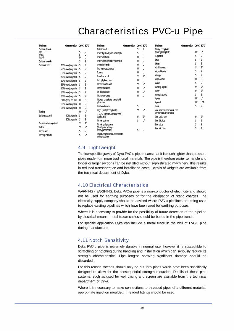
Characteristics PVC-u Pipe
4.9 LightweightThe low specific gravity of Dyka PVC-u pipe means that it is much lighter than pressurepipes made from more traditional materials. The pipe is therefore easier to handle andlonger or larger sections can be installed without sophisticated machinery. This resultsin reduced transportation and installation costs. Details of weights are available fromthe technical department of Dyka.
4.10 Electrical CharacteristicsWARNING - EARTHING. Dyka PVC-u pipe is a non-conductor of electricity and shouldnot be used for earthing purposes or for the dissipation of static charges. Theelectricity supply company should be advised where PVC-u pipelines are being usedto replace existing pipelines which have been used for earthing purposes.
Where it is necessary to provide for the possibility of future detection of the pipelineby electrical means, metal tracer cables should be buried in the pipe trench.
For specific application Dyka can include a metal trace in the wall of PVC-u pipeduring manufacture.
4.11 Notch SensitivityDyka PVC-u pipe is extremely durable in normal use, however it is susceptible toscratching or notching during handling and installation which can seriously reduce itsstrength characteristics. Pipe lengths showing significant damage should bediscarded.
For this reason threads should only be cut into pipes which have been specificallydesigned to allow for the consequential strength reduction. Details of these pipesystems, such as used for well casing and screen are available from the technicaldepartment of Dyka.
Where it is necessary to make connections to threaded pipes of a different material,appropriate injection moulded, threaded fittings should be used.
20
Sulphur dioxidedry S Smoist S Uliquid D USulphur trioxide S SSulphuric acid 10% (w/v) aq. soln. S S
20% (w/v) aq. soln. S S30% (w/v) aq. soln. S S40% (w/v) aq. soln. S S50% (w/v) aq. soln. S S55% (w/v) aq. soln. S S60% (w/v) aq. soln. S S70% (w/v) aq. soln. S S80% (w/v) aq. soln. S S90% (w/v) aq. soln D D
95% (w/v) aq. soln. D U98% (w/v) aq. soln. U U
fuming U* U*Sulphurous acid 10% aq. soln. S S
30% aq. soln. S SSurface active agents all S* S*Tallow S* S*Tannic acid S STanning extracts S S*
Tartaric acid˝ S STetraethyl lead (lead tetraethyl) STetrahydrofuran U UTetrahydronaphthalene (tetralin) U UThionyl chloride U UTitanium tetrachloride U UToluene U UTransformer oil S* S*Tributyl phosphate U UTrichloroacetic acid S* S*Trichlorobenzene U* U*Tri chloroethane U* U*Trichloroethylene U UTricresyl phosphate, see tritolyl phosphateTriethanolamine S UTrigol (triethylene glycold) S* S*3, 4, 5- Trihydroxybenzoic acid (gallic acid) S* S*Trimethylamine S U*Trimethylol propane (2-ethyl-2-hydroxy-methylpropanediol) S UTrisodium phosphate, see sodiumorthophosphate
Tritolyl phosphate (tricresylphosphate) U* U*Turpentine S SUrea S SUrine S SVanilla extract S* S*Vegetable oils S SVinegar S SVinyl acetate U UWater S SWetting agents S* S*Whey S* S*Wines & spirits S SXylene U* U*Xylenol U* U*EYeast S SZinc ammonium chloride, see ammonium zinc chlorideZinc carbonate S* S*Zinc chloride S SZinc oxide S SZinc sulphate S S
Medium Concentration 20°C 60°C Medium Concentration 20°C 60°C Medium Concentration 20°C 60°C
21
Characteristics PVC-u PipeParticular care should be taken where PVC-u pipe is being inserted into existing pipesor trenchless laying methods are being used.
In these instances the completed pipeline should be thoroughly tested in accordancewith the method detailed in section 9.19
To minimise the occurrence of pipe failure due to notching all Dyka manufacturedpipework is tested against the fracture toughness test detailed within BS 3505 : 1986(as amended) and WIS 4.31.06 : 1990. All Dyka manufactured pipes give a result inexcess of 4N/mm.
4.12 Impermeability To GasDyka PVC-u pipe is impermeable to gas and hence pipes carrying potable water canbe laid in close proximity to those carrying gas without fear of cross contamination.
4.13 Electrolytic ReactionAs Dyka PVC-u is a non-conductor of electricity it is not subject to electrolyticcorrosion and will not support such action when in contact with metal pipes or valves.
The usual care must be taken with the use of coated aluminium fittings to avoidcontact of dissimilar metals.
In particular, brass fittings must not be directly attached to coated aluminium tappingbands.
4.14 Behaviour in FirePVC-u does not support combustion and when the source of ignition is removed it isself extinguishing.
The principal doubt expressed with regard to the performance of PVC-u pipeworkduring an internal fire is that it would burn away leaving access for the fire to enteranother part of the structure. This has been investigated by the Fire Research Stationof the Building Research Establishment. Special investigation report number 9116,Ad Hoc fire tests on PVC-u services in buildings concluded that PVC-u pipes werefound to soften and close forming a carbonised mass that sealed the void.
However as an added precaution Dyka recommend that where pipes pass through afire stop that may give access to fire, intumescent seals should be installed. Providingcorrect attention is given to the installation of PVC-u internal systems, their use willnot aid the spread of fire any more than a conventional non-combustible system.
Tests show that the fumes created by burning PVC will not adversely affect structuralconcrete despite minor surface chloride deposition.
4.15 Abrasion ResistanceDue to the extremely low co-efficient of friction of Dyka PVC-u pipe it is particularlysuitable for the transportation of abrasive slurries. Dyka PVC-u pipe has been usedsuccessfully in a number of quarries, sand plants and open cast mines throughout theworld. Under such conditions its life expectancy has been established to exceed thatof equivalent steel pipeline by 2 to 3 times.
5. Working Characteristics
22
4.16 Impact StrengthAt very low temperatures (eg 0°C) the impact resistance of PVC-u is reduced. Wheninstalling pipelines at low temperatures extra care should be taken with handling andbackfilling..
All Dyka manufactured pipes are rigorously tested against the impact strengthsrequired by various national standards including BS 3505 and KIWA 49.
4.17 Biotic ResistanceStudies carried out at the University of Cairo conclude that PVC-u pipe will not sufferfrom rodent or biotic attack.
5.1 GeneralThe British Standard Code of Practice CP312 ‘Code of Practice for Plastic Pipework(Thermoplastic Material)’ deals in depth with many aspects of handling, installationand jointing. The following is a summary of the most important aspects of thesetechniques. However, Dyka recommend that the above publication is used forreference wherever possible.
5.2 Handling, Storage And TransportPVC-u pipes and fittings can become damaged during transport, handling or storage.CARE MUST BE TAKEN TO ENSURE THAT EACH ITEM IS FREE FROM DAMAGE PRIORTO INSTALLATION. The use of damaged pipes and fittings, may affect the performanceof the pipeline and they should be discarded.
5.2.1 Handling
While PVC-u pipe is light and easy to handle, it should not be maltreated. Theprotection of the pipe ends is particularly important.
Pipes and fittings should never be dropped to the ground. They should be unloadedfrom the transport either by hand or using slings and lifting equipment.
5.2.2 Storage
PVC-u pipe will distort under load and this is particularly evident at elevated or uneventemperatures. Whilst this distortion will not affect the performance of the pipe it maymake it difficult to joint. Stacks of pipes should therefore be protected from directsunlight or other heat sources if stored for extended periods.
Racks for long term storage should preferably provide continuous support along thepipe’s length, but if this is not possible then supports of 75mm (min) bearing widthsat 1 metre (max) centres should be placed beneath the pipes. If side restraints arerequired these can be at up to 2 metre spacing. Racks should not exceed 1 metre inheight.
Where racks are not available pipes can be stored on a temporary basis on theground, providing the surface is level and free from loose stones or other sharpprojections.

23
Working CharacteristicsWhere different sizes and classes of pipe are stored in the same rack, the heaviestpipes must be at the bottom and where pipes are nested inside one another the stackheight must be reduced in relation to the added weight.
Packs of pipes should remain intheir packing until ready for use.The complete packs can bestored directly onto level groundthat is free from loose stonesand other sharp projections.Packs of pipes can be stacked,however the total stack heightshould not exceed 3 metres.
5.2.3 TransportDyka PVC-u pipes should only be transported on vehicles with a flat bed that providesadequate support along the full length of the pipe. The bed of the vehicle must bethoroughly checked before loading to ensure that it is free from imperfections thatmay damage the pipes. Where side supports are required they should be smooth andnot more than 1.5m apart. An unsupported overhang at the rear of the vehicle shouldnot exceed 1m. As with storage the packs of pipe should be loaded with the heaviestat the bottom.
Pipe that arrives on site damaged should not be used and the incident should beadvised to Dyka immediately.
5.2.4 Handling & Storage - Advice to staff.
Do not:Remove protective packaging or securing straps from pipes until ready to use.
Drag or roll pipes or bundles into position.
Throw or drop pipe from delivery vehicles.
Use hooks, chains or metal slings when lifting.
Allow pipes or fittings to be stored near intense heat for long periods.
Exceed 3m high when stacking packs of pipes.
SupportBattens
Ground Level
1m Spacing
3m M
axim
um
1 m
etre
max
imum
1.5 metres maximum centres
1 metre maximum centres75mm minimum width
Working CharacteristicsDo:Protect pipes and fittings from being exposed to direct sunlight for long periods.
Store pipes on a suitable surface free from loose stones and sharp projections.
Ensure pipes and fittings do not come into contact with any aggressive chemicals(refer to Figure 13) in particular beware of solvents.
Use wide fabric or nylon slings for lifting.
Take special care handling slippery pipes in wet or frosty conditions.
Ensure adequate support is given when lifting long lengths of pipe.
5.3 Shipping InformationPVC-u pipe has a high volume to weight ratio. Where shipping or airfreight rates arecalculated on a volumetric basis the cube rate will apply in most cases.
Dyka solvent weld cement and cleaning fluid are classified as hazardous for shippingpurposes. When shipping these products they should be packed in full woodencartons according to I.M.C.O. regulations and shipped on deck at the mastersdiscretion.
5.4 Hazardous Shipping Details
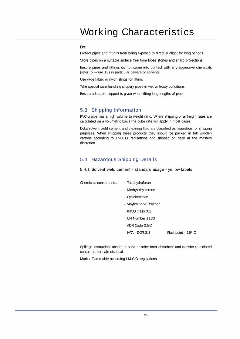
5.4.1 Solvent weld cement - standard usage - yellow labels
Chemicals constituents: - Tetrahydrofuran
- Methylethylketone
- Cyclohexanon
- Vinylchloride Polymer
IMCO Class 3.2
UN Number 1133
ADR Code 3.5C
IATA - DGR 3.3 Flashpoint - 16º C
Spillage instruction: absorb in sand or other inert absorbent and transfer to isolatedcontainers for safe disposal.
Marks: Flammable according I.M.C.O. regulations.
24
25
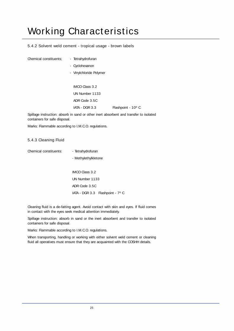
Working Characteristics5.4.2 Solvent weld cement - tropical usage - brown labels
Chemical constituents; - Tetrahydrofuran
- Cyclohexanon
- Vinylchloride Polymer
IMCO Class 3.2
UN Number 1133
ADR Code 3.5C
IATA - DGR 3.3 Flashpoint - 10º C
Spillage instruction: absorb in sand or other inert absorbent and transfer to isolatedcontainers for safe disposal.
Marks: Flammable according to I.M.C.O. regulations.
5.4.3 Cleaning Fluid
Chemical constituents: - Tetrahydrofuran
- Methylethylkletone
IMCO Class 3.2
UN Number 1133
ADR Code 3.5C
IATA - DGR 3.3 Flashpoint - 7º C
Cleaning fluid is a de-fatting agent. Avoid contact with skin and eyes. If fluid comesin contact with the eyes seek medical attention immediately.
Spillage instruction: absorb in sand or the inert absorbent and transfer to isolatedcontainers for safe disposal.
Marks: Flammable according to I.M.C.O. regulations.
When transporting, handling or working with either solvent weld cement or cleaningfluid all operatives must ensure that they are acquainted with the COSHH details.
6. Jointing6.1 GeneralOne of the major benefits of Dyka PVC-u pipes is the ability to use one of the threejointing methods below. This gives a great deal of flexibility in allowing for varyinginstallation conditions and the skill and equipment of the installers.
1. Solvent Cement
2. Ring Seal
3. Threaded Fittingssee also section 7.3 for fittings specifications
Before making any joint the pipe lengths and fittings should be thoroughly inspectedto ensure there is no transit damage. Any damaged items should be discarded.
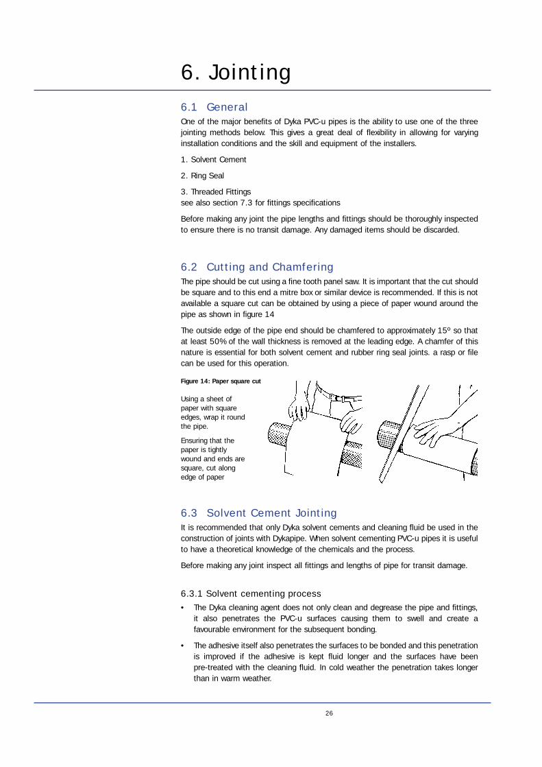
6.2 Cutting and ChamferingThe pipe should be cut using a fine tooth panel saw. It is important that the cut shouldbe square and to this end a mitre box or similar device is recommended. If this is notavailable a square cut can be obtained by using a piece of paper wound around thepipe as shown in figure 14
The outside edge of the pipe end should be chamfered to approximately 15º so thatat least 50% of the wall thickness is removed at the leading edge. A chamfer of thisnature is essential for both solvent cement and rubber ring seal joints. a rasp or filecan be used for this operation.
6.3 Solvent Cement JointingIt is recommended that only Dyka solvent cements and cleaning fluid be used in theconstruction of joints with Dykapipe. When solvent cementing PVC-u pipes it is usefulto have a theoretical knowledge of the chemicals and the process.
Before making any joint inspect all fittings and lengths of pipe for transit damage.
6.3.1 Solvent cementing process• The Dyka cleaning agent does not only clean and degrease the pipe and fittings,
it also penetrates the PVC-u surfaces causing them to swell and create afavourable environment for the subsequent bonding.
• The adhesive itself also penetrates the surfaces to be bonded and this penetrationis improved if the adhesive is kept fluid longer and the surfaces have been pre-treated with the cleaning fluid. In cold weather the penetration takes longerthan in warm weather.
26
Using a sheet ofpaper with squareedges, wrap it roundthe pipe.
Ensuring that thepaper is tightlywound and ends aresquare, cut alongedge of paper
Figure 14: Paper square cut
27
Jointing• Adhesives are formulated according to their usage and the type of PVC-u to be
bonded, only the correct adhesive should therefore be used. It is important tocheck that the adhesive used is still in good condition. Tins that contain lumps orhave a heavy surface film should be discarded. Under no circumstances shouldcleaning fluid be used as a thinner.
• Always use sufficient adhesive, work it in well and keep it fluid. If a less than perfect fit between the two mating surfaces has to be filled, apply several layers of adhesive, do not allow the last layer to dry before applying the next.
• The two surfaces must be mated in one movement while the adhesive is still wet and the PVC-u is still soft.
• Due to the softening power of the adhesive any excess must be removed, immediately the joint is made.
• Mated surfaces should be left undisturbed for 24 hours to allow the bond to cure.
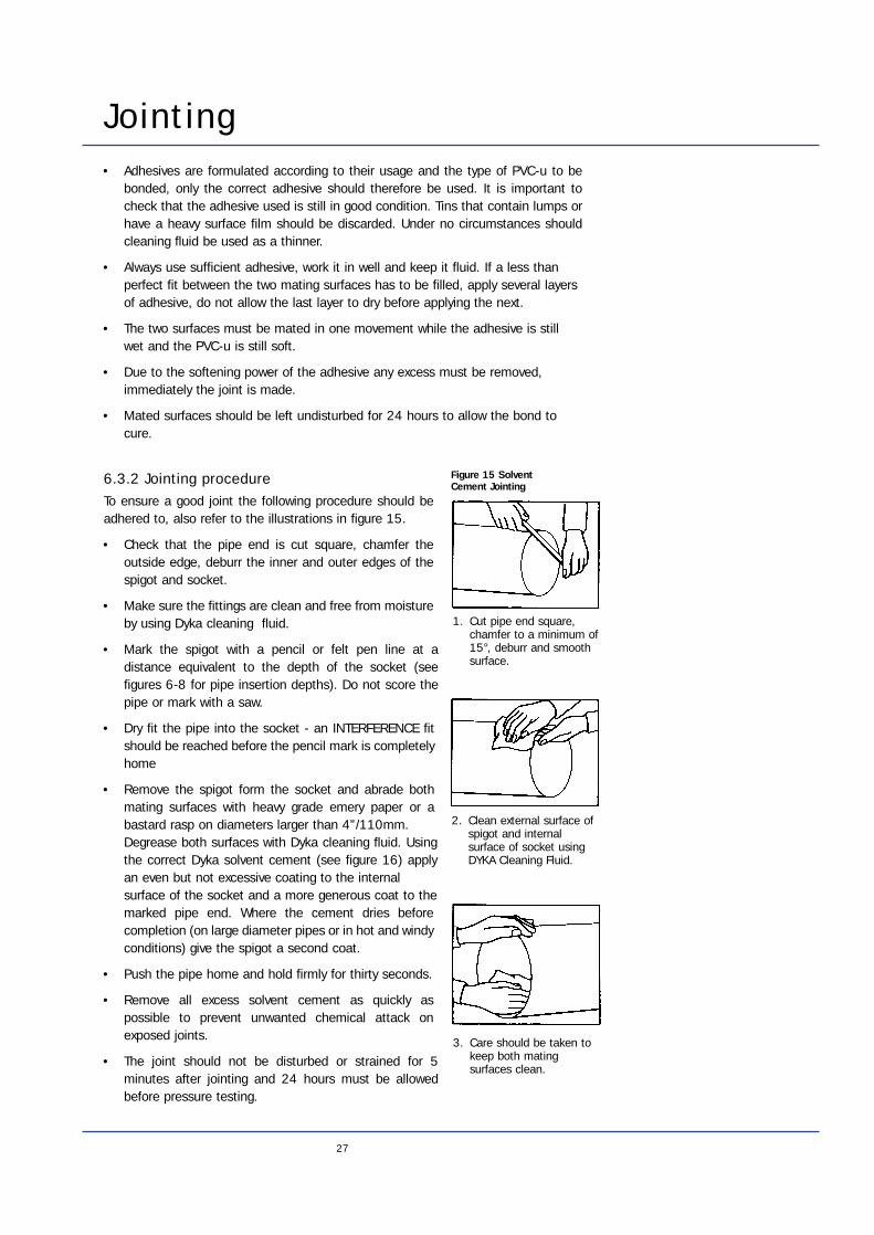
6.3.2 Jointing procedureTo ensure a good joint the following procedure should beadhered to, also refer to the illustrations in figure 15.
• Check that the pipe end is cut square, chamfer theoutside edge, deburr the inner and outer edges of thespigot and socket.
• Make sure the fittings are clean and free from moistureby using Dyka cleaning fluid.
• Mark the spigot with a pencil or felt pen line at adistance equivalent to the depth of the socket (seefigures 6-8 for pipe insertion depths). Do not score thepipe or mark with a saw.
• Dry fit the pipe into the socket - an INTERFERENCE fitshould be reached before the pencil mark is completelyhome
• Remove the spigot form the socket and abrade bothmating surfaces with heavy grade emery paper or abastard rasp on diameters larger than 4”/110mm. Degrease both surfaces with Dyka cleaning fluid. Usingthe correct Dyka solvent cement (see figure 16) applyan even but not excessive coating to the internal surface of the socket and a more generous coat to themarked pipe end. Where the cement dries beforecompletion (on large diameter pipes or in hot and windyconditions) give the spigot a second coat.
• Push the pipe home and hold firmly for thirty seconds.
• Remove all excess solvent cement as quickly aspossible to prevent unwanted chemical attack onexposed joints.
• The joint should not be disturbed or strained for 5minutes after jointing and 24 hours must be allowedbefore pressure testing.
1. Cut pipe end square,chamfer to a minimum of15°, deburr and smoothsurface.
2. Clean external surface ofspigot and internalsurface of socket usingDYKA Cleaning Fluid.
3. Care should be taken tokeep both matingsurfaces clean.
Figure 15 Solvent Cement Jointing
Jointing
Type of cement Label Packing Application
PVC cement for pressure Yellow Tins 1 litre Small bore systems up to 90mm/3" Tubes 125 gram pressure systemsoutside diameter Tins 1⁄4 Litre
PVC cement for pressure Brown HD Tins 1 litre Tropical use. Largesystems 4” and above Tins 1⁄4 Litre diameter systems
PVC cleaning fluid Grey Tins 1 litre Degreasing in Tins 1⁄4 Litre preparation for bonding
6.3.3 Extreme conditionsCold - Under extremely cold conditions, special care must be taken to ensure excesssolvent cement is not allowed to enter into the pipeline as this could result in solventcracking of the pipe
Hot - In hot weather, particularly when solvent cementing long lengths, the pipeshould be well ventilated. In some cases forced ventilation will be necessary.
6.3.4 CautionEnsure adequate ventilation when solvent cementing.
If swallowed do not induce vomiting and seek medical attention.
If splashed on face or eyes, wash liberally with clean water and seek medicalattention.
See Appendix 5 for health and safety guidance.
Adhesive and cleaning fluid are hazardous chemicals. Ensure that empty tins, soiledcloth and paper are disposed of correctly and not left in the pipe trench.
28
Nominal size of pipe mm 16 20 25 32 40 50 63 90 110 140 160 200
Nominal size of pipe imperial 3⁄8" 1⁄2" 3⁄4" 1" 11⁄4" 11⁄2" 2" 3" 4" 5" 6" 8"
Average number joints per litre 600 350 260 190 140 75 70 60 40 30 25 17
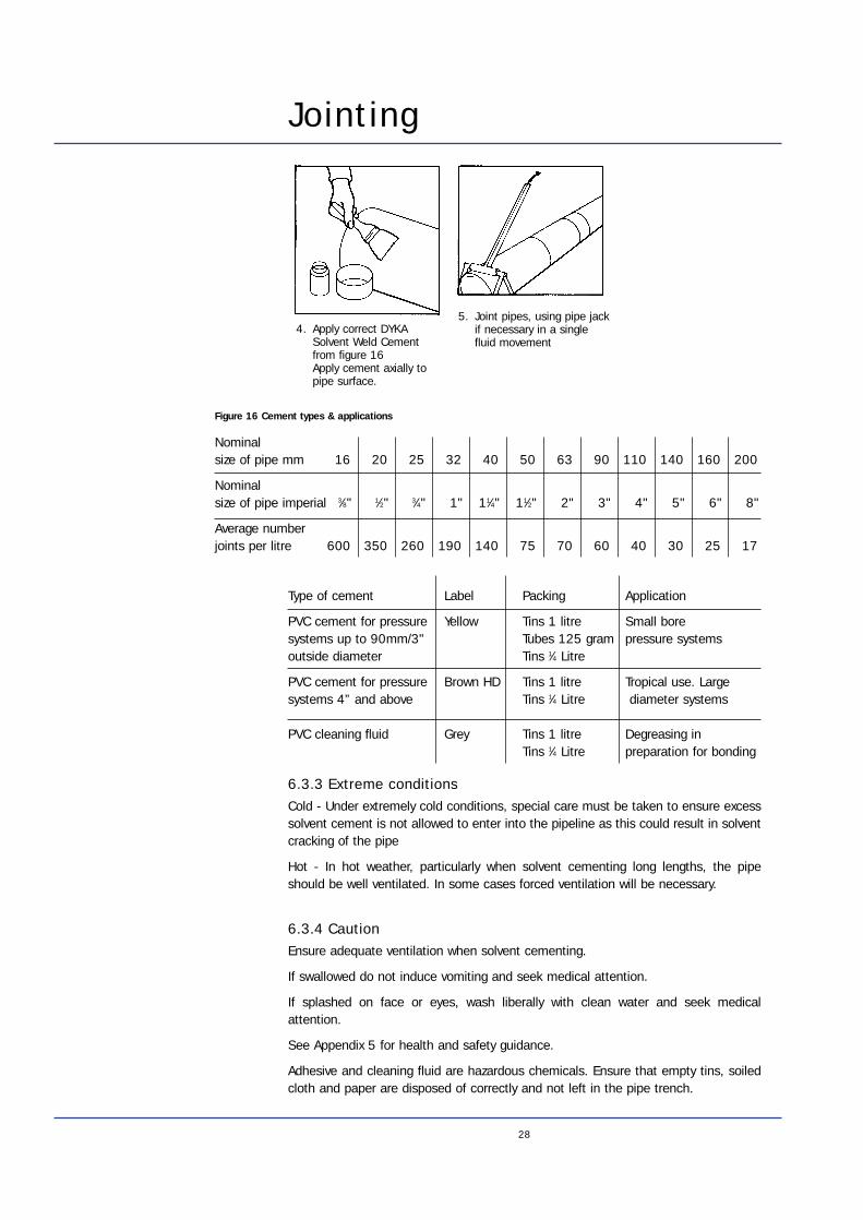
4. Apply correct DYKASolvent Weld Cementfrom figure 16 Apply cement axially topipe surface.
5. Joint pipes, using pipe jackif necessary in a singlefluid movement
Figure 16 Cement types & applications
29
Jointing6.3.5 Possible errors when bonding PVC-u• Pipe end not cut squarely
• Pipe end not deburred and chamfered
• Moisture and dirt on glued surface
• Not properly cleaned or dried
• Brush still wet with cleaner
• Adhesive not evenly spread
• Adhesive not brushed out axially
• Adhesive on only one of the two surfaces
• Pipe and accessory not assembled in time
• Pipe not pushed home to shoulder
• Incorrect adhesive used. Adhesive type did not match the application
• The gap too big to be filled completely, leaving passages through the adhesive
• During assembly of pipe and accessories, one of the fittings has been twisted relative to the other
• Adjusting after jointing, occurred too late, causing the already cured adhesive to be broken apart
• The drying time not adhered to
• No attention paid to the presence of water or damp conditions (condensation)
• Ventilation too drastic causing adhesive to dry during application (skin forming)
• Adhesive no longer homogeneous, caused by the tin being left open for too long
• Use of incorrect cleaning agent
• Oil or oil containing substances contaminated joint surfaces causing bond failure
• Bonding took place at sub zero temperatures without the necessary precautions
6.4 Ring seal jointingThe assembly procedure for the Dykapipe mechanical Joint System is outlined below,refer also to figure 17 Ring Seal Jointing
Before making any joint inspect all fittings and lengths of pipe for transit damage.
6.4.1 Jointing procedure• Deburr and smooth the pipe spigot, cut the chamfer, and mark on a depth of
entry line with a pencil or felt pen (see figures 6-8 for insertion depths).
• Clean both socket and ring, particularly the inside of the groove of the socket.
• Check the ring is correctly inserted, and seated. Incorrectly seated seal rings can be easily repositioned by applying hot water to the ring seal and captivating ring (only present in Forsheda seal rings).
• Make sure that the pipes align correctly in both planes. THIS IS MOST IMPORTANT,do not try to insert the spigot at an angle.
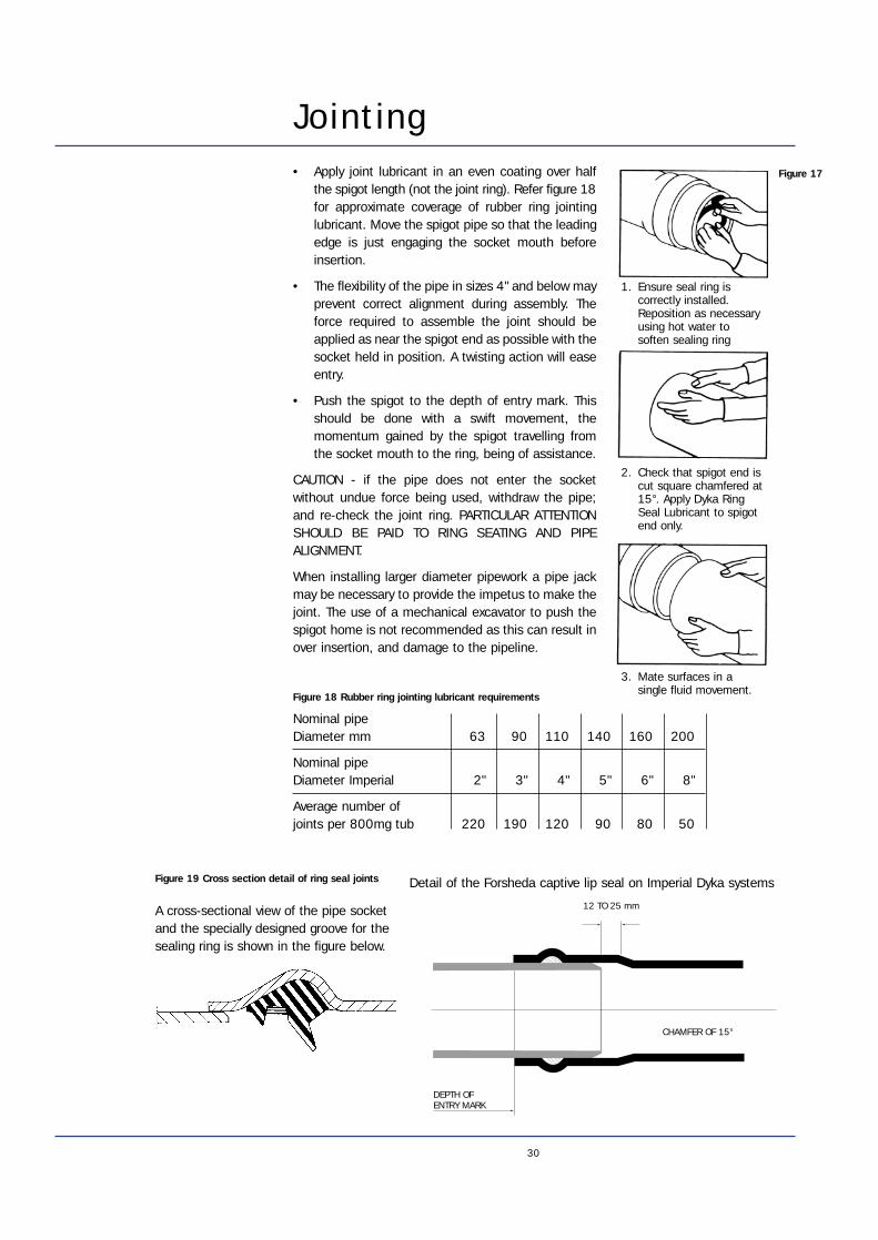
Jointing• Apply joint lubricant in an even coating over half
the spigot length (not the joint ring). Refer figure 18for approximate coverage of rubber ring jointinglubricant. Move the spigot pipe so that the leadingedge is just engaging the socket mouth beforeinsertion.
• The flexibility of the pipe in sizes 4" and below mayprevent correct alignment during assembly. Theforce required to assemble the joint should beapplied as near the spigot end as possible with thesocket held in position. A twisting action will easeentry.
• Push the spigot to the depth of entry mark. Thisshould be done with a swift movement, themomentum gained by the spigot travelling fromthe socket mouth to the ring, being of assistance.
CAUTION - if the pipe does not enter the socketwithout undue force being used, withdraw the pipe;and re-check the joint ring. PARTICULAR ATTENTIONSHOULD BE PAID TO RING SEATING AND PIPEALIGNMENT.
When installing larger diameter pipework a pipe jackmay be necessary to provide the impetus to make thejoint. The use of a mechanical excavator to push thespigot home is not recommended as this can result inover insertion, and damage to the pipeline.
30
1. Ensure seal ring iscorrectly installed.Reposition as necessaryusing hot water tosoften sealing ring
2. Check that spigot end iscut square chamfered at15°. Apply Dyka RingSeal Lubricant to spigotend only.
3. Mate surfaces in asingle fluid movement.
CHAMFER OF 15°
12 TO 25 mm
DEPTH OFENTRY MARK
A cross-sectional view of the pipe socketand the specially designed groove for thesealing ring is shown in the figure below.
Detail of the Forsheda captive lip seal on Imperial Dyka systems
Nominal pipeDiameter mm 63 90 110 140 160 200
Nominal pipeDiameter Imperial 2" 3" 4" 5" 6" 8"
Average number ofjoints per 800mg tub 220 190 120 90 80 50
Figure 18 Rubber ring jointing lubricant requirements
Figure 17
Figure 19 Cross section detail of ring seal joints
31
Jointing• The pipe should be marked (not with a saw) so that the spigot enters the socket
to within 12-25mm of the bottom of the socket (Dimension A, figure 19 Crosssection detail of ring seal joint)
• If installing above ground, check entry depth after installation.
• As with all pipe jointing, cleanliness is of prime importance and pipes, especiallyspigot ends, should be supported clear of the ground to prevent dirt beingsmeared on with the lubricant. Placing the pipes on blocks also reduces frictionand consequently facilitates the making of the joint. THESE BLOCKS MUST BEREMOVED BEFORE BACKFILLING.
• The pipeline should be pressure tested after the first 300 to 400 metres havebeen installed. After this, tests should be carried out at convenient intervalspreferably not exceeding 1 kilometre.
6.5 Threaded JointsWhere it is necessary to join Dyka PVC-u pipe to another type of pipe using a threadedjoint, Dyka recommend the following guidelines:
• Wherever possible make the connection with the PVC-u pipe as the malecomponent of the joint.
• Use only P.T.F.E. tape as a sealant.
• Tighten to firm hand tightness only using strap wrenches - do not use serrated jawwrenches.
A full range of adaptors is available to connect Dyka PVC-u pipe to other materialsplease contact the technical department Dyka.
6.6 Saddle JointsDyka offer a comprehensive range of saddle joints for use with a variety of pipe sizes.Single branch saddles are available in clamp or wedge designs and double branchclamp models in clamp design to fit mains pipes up to 250mm diameter.
6.7 Flange JointingTo enable jointing of Dyka PVC-u pipelines to pipes, valves or vessels of differentmaterials PVC-u flange adaptors are available, though care has to be exercised intheir use.
Allowances have to be made for the different methods of measuring PVC-u pipe andfor instance ductile iron piping. For example PVC-u pipe is sized according to itsoutside diameter and ductile iron by its internal bore. In addition the different wallthicknesses of these different materials cause incompatibilities between internal boreand outside diameters.
To overcome this Dyka offer a range of adaptors and converters to allow effectiveconnections in most applications.
6.7.1 Standard stub and backing ringThis allows PVC-u pipe to be easily attached to pipelines made from other materialsand provides a clear bore equivalent to the PVC-u pipe. This may however mean thatthe bore of the other pipe material is reduced down to that of the PVC-u.
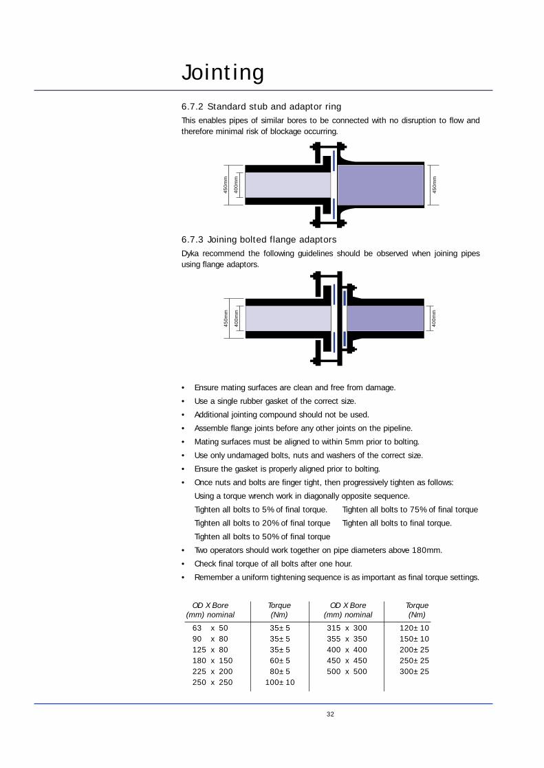
Jointing6.7.2 Standard stub and adaptor ringThis enables pipes of similar bores to be connected with no disruption to flow andtherefore minimal risk of blockage occurring.
6.7.3 Joining bolted flange adaptorsDyka recommend the following guidelines should be observed when joining pipesusing flange adaptors.
• Ensure mating surfaces are clean and free from damage.
• Use a single rubber gasket of the correct size.
• Additional jointing compound should not be used.
• Assemble flange joints before any other joints on the pipeline.
• Mating surfaces must be aligned to within 5mm prior to bolting.
• Use only undamaged bolts, nuts and washers of the correct size.
• Ensure the gasket is properly aligned prior to bolting.
• Once nuts and bolts are finger tight, then progressively tighten as follows:
Using a torque wrench work in diagonally opposite sequence.
Tighten all bolts to 5% of final torque. Tighten all bolts to 75% of final torque
Tighten all bolts to 20% of final torque Tighten all bolts to final torque.
Tighten all bolts to 50% of final torque
• Two operators should work together on pipe diameters above 180mm.
• Check final torque of all bolts after one hour.
• Remember a uniform tightening sequence is as important as final torque settings.
32
450m
m
450m
m
400m
m
450m
m
400m
m
400m
m
63 x 5090 x 80125 x 80180 x 150225 x 200250 x 250
35±535±535±560±580±5
100±10
315 x 300355 x 350400 x 400450 x 450500 x 500
120±10150±10200±25250±25300±25
OD X Bore (mm) nominal
Torque(Nm)
OD X Bore (mm) nominal
Torque(Nm)
33
7. Water Hammer/ Pressure Surges7.1 GeneralA moving column of water has momentum proportional to its weight and velocity.When this flow is stopped suddenly this inertia is converted into a shock load orpressure surge known as “Water Hammer”. The greater the quantity of liquid and thefluid velocity the greater the shock loading.
Dyka PVC-u pipe has excellent fatigue strength and allowances for intermittentfluctuations and surge pressures, such as increasing pipe pressure rating or reducingnormal working pressures, are not normally necessary.
However, excessive surge pressure can cause the failure of a pressure system and forthis reason the following precautions are recommended:
• Avoid the use of fast opening and closing valves.
• Provide for pressure relief where surges are likely to occur for other reasons, suchas pump failure.
• Major pressure surge is likely to occur, due to valve closure, when:
The valve closing time ≤ 2La
Where: L = pipeline length (m)a = surge wave velocity (m/sec) (see figure 20)
• The increase in pressure due to the effect of Pressure Surge can be calculated bythe formula:
H = a DVg
Where H = Water Hammer, pressure increase in bar.
a = Surge wave velocity (see figure qq)
g = Gravity
∆V = Change in velocity
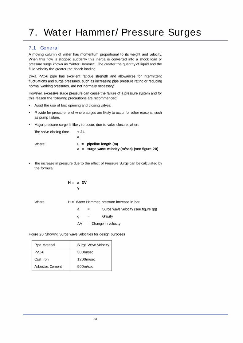
Figure 20 Showing Surge wave velocities for design purposes
Pipe Material Surge Wave Velocity
PVC-u 300m/sec
Cast Iron 1200m/sec
Asbestos Cement 900m/sec
34
8. Pipe Installation8.1 GeneralThe simplicity of the installation procedure for Dyka PVC-u pipe offers considerablebenefits especially in terms of time and the consequent cost saving.
The following is general information on installation techniques. For more specificguidance reference should be made to:
CP312 ‘Code of Practice for the Plastic Pipework’ and Appendix 6 Water AuthoritiesAssociation Guidelines.
Dyka PVC-u pipe is a semi-flexible conduit and as such can deflect considerablywithout damage.
Its response to earth loading is not governed by pipe strength, but rather by theinteraction of the soil and the pipe. It is therefore very important that all aspects ofpipe laying, particularly bedding and sidefill, receive special attention.
8.2 TemperatureParticular care should be exercised when installing pipes at temperatures below 10°C. Pipe laying should not be carried out when the temperature is below 0°C.
8.3 Trench ExcavationAs a general rule trench excavation should not be carried out too far ahead of the pipelaying as slumping and collapse of the trench wall may occur.
During excavation and laying of unusually deep pipelines the trench walls should besupported with an appropriate system to safeguard the installation personnel againstcollapse of the trench.
The excavated soil should be kept well back from the edge of the trench and loosestones removed and discarded.
8.4 Trench WidthsThe narrower the trench in which PVC-u pipe is laid, the less the load it has to carry.Trench width should, therefore, be kept to a minimum but it must be sufficient to allowthe proper placing and compaction of bedding material against each quadrant of thepipe. For this purpose it is recommended that, at the crown of the pipe, the trenchwidth should be 300mm (+50mm) wider than the diameter of the pipe. Above thecrown the trench may be any convenient width.
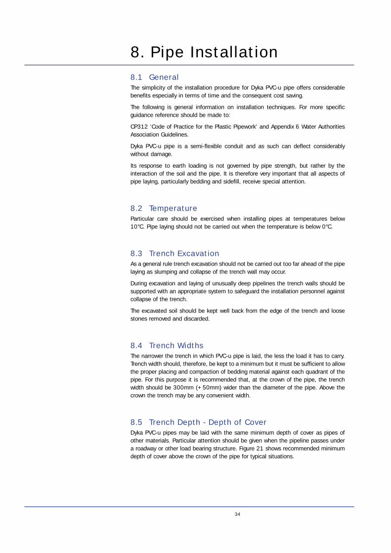
8.5 Trench Depth - Depth of CoverDyka PVC-u pipes may be laid with the same minimum depth of cover as pipes ofother materials. Particular attention should be given when the pipeline passes undera roadway or other load bearing structure. Figure 21 shows recommended minimumdepth of cover above the crown of the pipe for typical situations.
Pipe InstallationFigure 21 Recommended minimum depth of cover
Location Depth of Covering
Roads & Streets (at maximum DOE loading) 1000mm
Driveways 750mm
Footpaths and Gardens 500mm
Open Country 1000mm
8.6 BeddingThe trench should be over excavated to a depth equivalent to the nominal diameterof the pipe or a maximum of 100mm. The underbed should be filled and thoroughlycompacted with bedding material which conforms to WIS 4-08-01 or meets theparticle size and compaction requirements given in section 9.8 below.
Care must be taken to ensure continuous support is given along the entire pipe lengthand not just on the joints. The bedding should be scooped out to accommodate jointsand fittings.
In all cases the underbed should be laid to the correct fall and gradient.
8.7 Sidefill, Backfill and CompactionWhen in place in the trench the weight of overlying earth tends to force down the topof the pipe, but for distortion to be possible, the sides must move out a correspondingdistance.
Such movement of the side walls is only possible to the extent that the beddingmaterial around the pipe can move. The firmer that this bedding material is, thegreater the force required to move it and consequently the greater the external loadthe pipe can safely carry. It is, therefore, very important that bedding and sidefillmaterial and the compaction process meet the correct specifications.
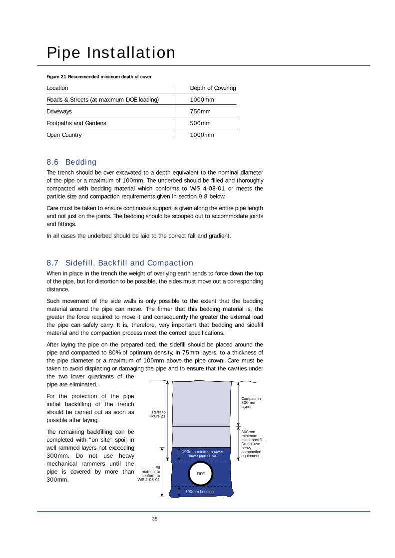
After laying the pipe on the prepared bed, the sidefill should be placed around thepipe and compacted to 80% of optimum density, in 75mm layers, to a thickness ofthe pipe diameter or a maximum of 100mm above the pipe crown. Care must betaken to avoid displacing or damaging the pipe and to ensure that the cavities underthe two lower quadrants of thepipe are eliminated.
For the protection of the pipeinitial backfilling of the trenchshould be carried out as soon aspossible after laying.
The remaining backfilling can becompleted with “on site” spoil inwell rammed layers not exceeding300mm. Do not use heavymechanical rammers until thepipe is covered by more than300mm.
35
100mm minimum coverabove pipe crown
Refer toFigure 21
300mm minimuminitial backfill.Do not use heavy compaction equipment.
Compact in 300mm layers
Fillmaterial toconform to
WIS 4-08-01PIPE
100mm bedding
36
Pipe Installation
8.8 Test For Suitability Of Soil Material ForSurrounding Buried PVC-u PipeThe suitability of the bedding and backfilling material can be determined in one of twoways. Either by estimating the approximate particle size or by calculating thecompaction fraction of the material. Under both methods it is necessary to obtain arepresentative sample of the proposed material. This is done by taking about 50kg ofthe material and heaping it on a clear surface. The pile is equally quartered and twoopposing quarters are selected, the remainder is removed. The retained quarters areremixed to form a new pile and the process is repeated until the required sample sizeis obtained.
Method 1 Particle Size
The maximum particle size should not exceed 20mm but a small percentage ofparticles between 20mm and 40mm is acceptable. If particles over 40mm arepresent the material should be rejected. In cases of doubt, a representative sampleof the material weighing about 2kg should be sieved, using 20mm and 40mm BritishStandard approved test sieves (BS 410 ‘Test Sieve’).
When sieving, clumps of material that break up under light finger pressure may behelped through the sieve, but force should not be used to squeeze oversize lumpsthrough the mesh. The material should be rejected if:
a) any particles are retained on the 40mm sieve or
b) more than 5% by mass is retained on the 20mm sieve.
For sharp, hard materials these particle size limitations should be halved (i.e. max.size 10mm and 20mm).
Where scouring of the bed under the pipeline may be caused by adverse ground waterconditions the prepared bedding material should be of a particle size smaller than10mm to prevent loss of support to the pipeline.
Method 2 Ease of Compaction
1. Place a 250mm length of 160mm O.D. pipe on a clear surface.
2. Fill the length of pipe loosely with a representative sample of the proposedmaterial and level off to the top of the pipe.
3. Lift the pipe off the sample and place it on a clear surface.
4. Replace about a quarter of the sample into the pipe and compact it using arammer of approximately 1kg weight. Repeat this process until all the sample hasbeen returned to the pipe. Measure the distance the material has compacted (X)and refer to Figure 22 to determine the suitability of the material.
Dimension of X Compaction Fraction Suitability of Material
+ 50mm 0.20 Suitable
50 - 75mm 0.20 - 0.30 Not suitable if ground is subject to waterlogged conditions after laying.
> 75mm > 0.30 Not Suitable
Figure 22 Compaction test - material suitability.
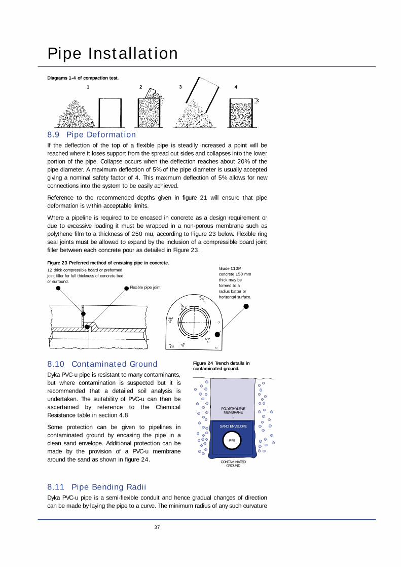
Pipe Installation
8.9 Pipe DeformationIf the deflection of the top of a flexible pipe is steadily increased a point will bereached where it loses support from the spread out sides and collapses into the lowerportion of the pipe. Collapse occurs when the deflection reaches about 20% of thepipe diameter. A maximum deflection of 5% of the pipe diameter is usually acceptedgiving a nominal safety factor of 4. This maximum deflection of 5% allows for newconnections into the system to be easily achieved.
Reference to the recommended depths given in figure 21 will ensure that pipedeformation is within acceptable limits.
Where a pipeline is required to be encased in concrete as a design requirement ordue to excessive loading it must be wrapped in a non-porous membrane such aspolythene film to a thickness of 250 mu, according to Figure 23 below. Flexible ringseal joints must be allowed to expand by the inclusion of a compressible board jointfiller between each concrete pour as detailed in Figure 23.
37
12 thick compressible board or preformedjoint filler for full thickness of concrete bedor surround.
Flexible pipe joint
Grade C10Pconcrete 150 mmthick may beformed to aradius batter orhorizontal surface.
8.10 Contaminated GroundDyka PVC-u pipe is resistant to many contaminants,but where contamination is suspected but it isrecommended that a detailed soil analysis isundertaken. The suitability of PVC-u can then beascertained by reference to the ChemicalResistance table in section 4.8
Some protection can be given to pipelines incontaminated ground by encasing the pipe in aclean sand envelope. Additional protection can bemade by the provision of a PVC-u membranearound the sand as shown in figure 24.
8.11 Pipe Bending RadiiDyka PVC-u pipe is a semi-flexible conduit and hence gradual changes of directioncan be made by laying the pipe to a curve. The minimum radius of any such curvature
Diagrams 1-4 of compaction test.
Figure 23 Preferred method of encasing pipe in concrete.
PIPE
CONTAMINATEDGROUND
POLYETHYLENEMEMBRANE
SAND ENVELOPE
Figure 24 Trench details incontaminated ground.
1 2 3 4
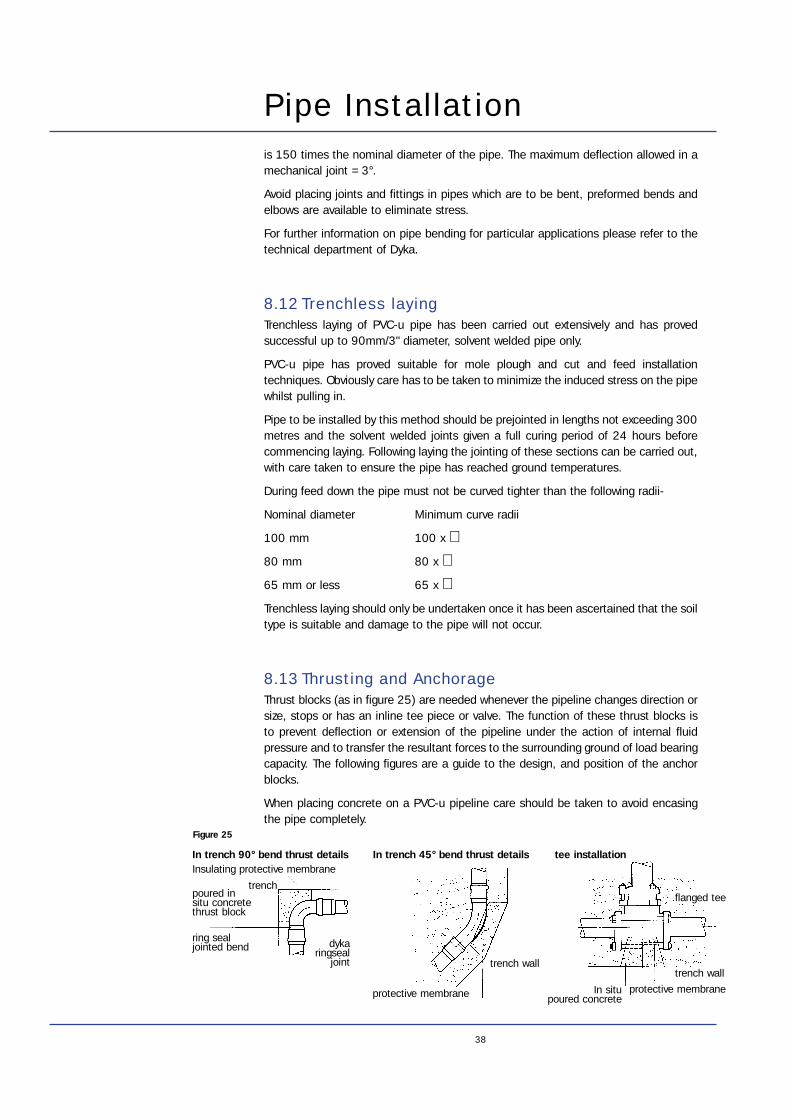
is 150 times the nominal diameter of the pipe. The maximum deflection allowed in amechanical joint =3°.
Avoid placing joints and fittings in pipes which are to be bent, preformed bends andelbows are available to eliminate stress.
For further information on pipe bending for particular applications please refer to thetechnical department of Dyka.
8.12 Trenchless layingTrenchless laying of PVC-u pipe has been carried out extensively and has provedsuccessful up to 90mm/3" diameter, solvent welded pipe only.
PVC-u pipe has proved suitable for mole plough and cut and feed installationtechniques. Obviously care has to be taken to minimize the induced stress on the pipewhilst pulling in.
Pipe to be installed by this method should be prejointed in lengths not exceeding 300metres and the solvent welded joints given a full curing period of 24 hours beforecommencing laying. Following laying the jointing of these sections can be carried out,with care taken to ensure the pipe has reached ground temperatures.
During feed down the pipe must not be curved tighter than the following radii-
Nominal diameter Minimum curve radii
100 mm 100 x ∅ 80 mm 80 x ∅ 65 mm or less 65 x ∅Trenchless laying should only be undertaken once it has been ascertained that the soiltype is suitable and damage to the pipe will not occur.
8.13 Thrusting and AnchorageThrust blocks (as in figure 25) are needed whenever the pipeline changes direction orsize, stops or has an inline tee piece or valve. The function of these thrust blocks isto prevent deflection or extension of the pipeline under the action of internal fluidpressure and to transfer the resultant forces to the surrounding ground of load bearingcapacity. The following figures are a guide to the design, and position of the anchorblocks.
When placing concrete on a PVC-u pipeline care should be taken to avoid encasingthe pipe completely.
38
Pipe Installation
In trench 90° bend thrust detailsInsulating protective membrane
trenchpoured insitu concretethrust block
ring sealjointed bend dyka
ringsealjoint
In trench 45° bend thrust details
trench wall
protective membrane
flanged tee
trench wall
protective membraneIn situ poured concrete
tee installation
Figure 25
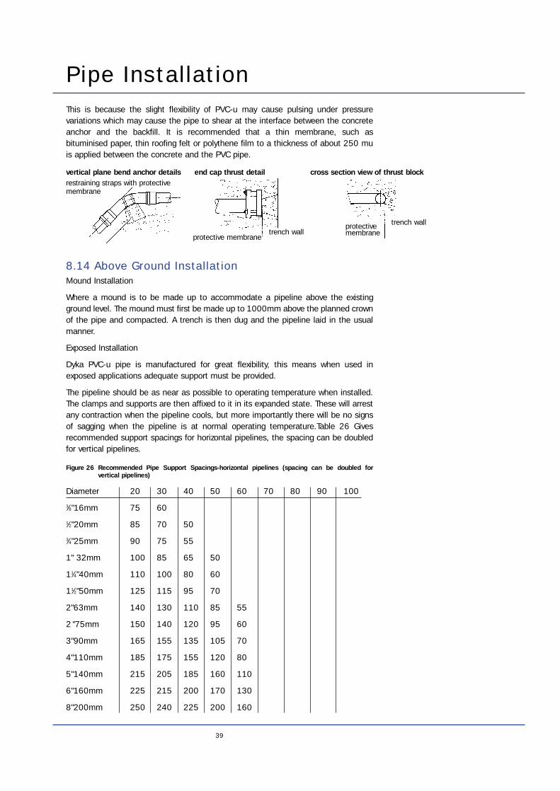
Pipe InstallationThis is because the slight flexibility of PVC-u may cause pulsing under pressurevariations which may cause the pipe to shear at the interface between the concreteanchor and the backfill. It is recommended that a thin membrane, such asbituminised paper, thin roofing felt or polythene film to a thickness of about 250 muis applied between the concrete and the PVC pipe.
8.14 Above Ground InstallationMound Installation
Where a mound is to be made up to accommodate a pipeline above the existingground level. The mound must first be made up to 1000mm above the planned crownof the pipe and compacted. A trench is then dug and the pipeline laid in the usualmanner.
Exposed Installation
Dyka PVC-u pipe is manufactured for great flexibility, this means when used inexposed applications adequate support must be provided.
The pipeline should be as near as possible to operating temperature when installed.The clamps and supports are then affixed to it in its expanded state. These will arrestany contraction when the pipeline cools, but more importantly there will be no signsof sagging when the pipeline is at normal operating temperature.Table 26 Givesrecommended support spacings for horizontal pipelines, the spacing can be doubledfor vertical pipelines.
Figure 26 Recommended Pipe Support Spacings-horizontal pipelines (spacing can be doubled forvertical pipelines)
Diameter 20 30 40 50 60 70 80 90 100
3⁄8"16mm 75 60
1⁄2"20mm 85 70 50
3⁄4"25mm 90 75 55
1" 32mm 100 85 65 50
11⁄4"40mm 110 100 80 60
11⁄2"50mm 125 115 95 70
2"63mm 140 130 110 85 55
2 "75mm 150 140 120 95 60
3"90mm 165 155 135 105 70
4"110mm 185 175 155 120 80
5"140mm 215 205 185 160 110
6"160mm 225 215 200 170 130
8"200mm 250 240 225 200 160
39
vertical plane bend anchor details end cap thrust detailrestraining straps with protectivemembrane
protective membranetrench wall
protectivemembrane
cross section view of thrust block
trench wall
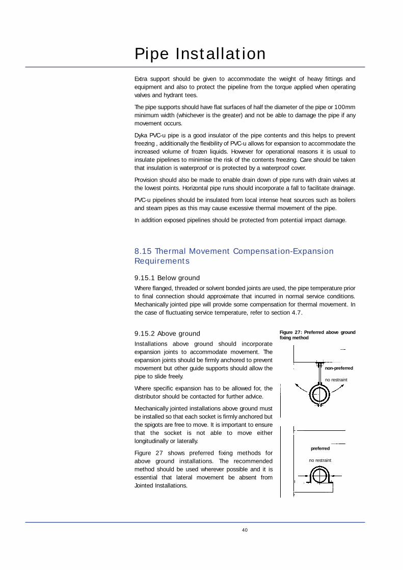
40
Pipe InstallationExtra support should be given to accommodate the weight of heavy fittings andequipment and also to protect the pipeline from the torque applied when operatingvalves and hydrant tees.
The pipe supports should have flat surfaces of half the diameter of the pipe or 100mmminimum width (whichever is the greater) and not be able to damage the pipe if anymovement occurs.
Dyka PVC-u pipe is a good insulator of the pipe contents and this helps to preventfreezing , additionally the flexibility of PVC-u allows for expansion to accommodate theincreased volume of frozen liquids. However for operational reasons it is usual toinsulate pipelines to minimise the risk of the contents freezing. Care should be takenthat insulation is waterproof or is protected by a waterproof cover.
Provision should also be made to enable drain down of pipe runs with drain valves atthe lowest points. Horizontal pipe runs should incorporate a fall to facilitate drainage.
PVC-u pipelines should be insulated from local intense heat sources such as boilersand steam pipes as this may cause excessive thermal movement of the pipe.
In addition exposed pipelines should be protected from potential impact damage.
8.15 Thermal Movement Compensation-ExpansionRequirements
9.15.1 Below groundWhere flanged, threaded or solvent bonded joints are used, the pipe temperature priorto final connection should approximate that incurred in normal service conditions.Mechanically jointed pipe will provide some compensation for thermal movement. Inthe case of fluctuating service temperature, refer to section 4.7.
9.15.2 Above groundInstallations above ground should incorporateexpansion joints to accommodate movement. Theexpansion joints should be firmly anchored to preventmovement but other guide supports should allow thepipe to slide freely.
Where specific expansion has to be allowed for, thedistributor should be contacted for further advice.
Mechanically jointed installations above ground mustbe installed so that each socket is firmly anchored butthe spigots are free to move. It is important to ensurethat the socket is not able to move eitherlongitudinally or laterally.
Figure 27 shows preferred fixing methods for above ground installations. The recommendedmethod should be used wherever possible and it isessential that lateral movement be absent fromJointed Installations.
non-preferred
no restraint
preferred
no restraint
Figure 27: Preferred above groundfixing method
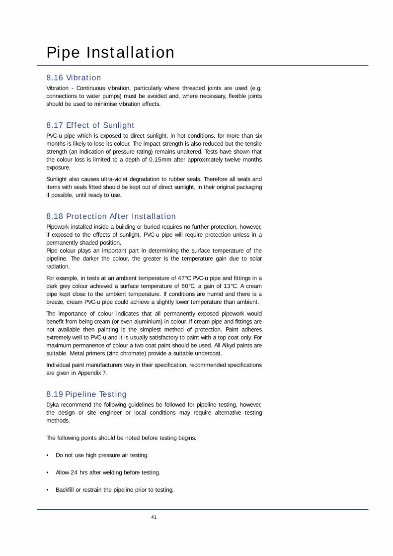
Pipe Installation8.16 VibrationVibration - Continuous vibration, particularly where threaded joints are used (e.g.connections to water pumps) must be avoided and, where necessary, flexible jointsshould be used to minimise vibration effects.
8.17 Effect of SunlightPVC-u pipe which is exposed to direct sunlight, in hot conditions, for more than sixmonths is likely to lose its colour. The impact strength is also reduced but the tensilestrength (an indication of pressure rating) remains unaltered. Tests have shown thatthe colour loss is limited to a depth of 0.15mm after approximately twelve monthsexposure.
Sunlight also causes ultra-violet degradation to rubber seals. Therefore all seals anditems with seals fitted should be kept out of direct sunlight, in their original packagingif possible, until ready to use.
8.18 Protection After InstallationPipework installed inside a building or buried requires no further protection, however,if exposed to the effects of sunlight, PVC-u pipe will require protection unless in apermanently shaded position.Pipe colour plays an important part in determining the surface temperature of thepipeline. The darker the colour, the greater is the temperature gain due to solarradiation.
For example, in tests at an ambient temperature of 47°C PVC-u pipe and fittings in adark grey colour achieved a surface temperature of 60°C, a gain of 13°C. A creampipe kept close to the ambient temperature. If conditions are humid and there is abreeze, cream PVC-u pipe could achieve a slightly lower temperature than ambient.
The importance of colour indicates that all permanently exposed pipework wouldbenefit from being cream (or even aluminium) in colour. If cream pipe and fittings arenot available then painting is the simplest method of protection. Paint adheresextremely well to PVC-u and it is usually satisfactory to paint with a top coat only. Formaximum permanence of colour a two coat paint should be used. All Alkyd paints aresuitable. Metal primers (zinc chromate) provide a suitable undercoat.
Individual paint manufacturers vary in their specification, recommended specificationsare given in Appendix 7.
8.19 Pipeline TestingDyka recommend the following guidelines be followed for pipeline testing, however,the design or site engineer or local conditions may require alternative testingmethods.
The following points should be noted before testing begins.
• Do not use high pressure air testing.
• Allow 24 hrs after welding before testing.
• Backfill or restrain the pipeline prior to testing.
41
Pipe Installation
42
• Leave joints exposed.
• Test with all valves in fully open position.
• Test sections should not exceed 1 kilometre.
Proceed with the testing as follows:
1. Blank off all ends and bolster them against pressure.
2. Insert air bleed valves at all the highest points along the pipeline.
3. Insert a pressure gauge capable of reading pressure changes of 1% of testpressure at the lowest point of the pipeline.
4. Slowly fill the pipeline with water, take care to avoid risk of damage due to pressure surge.
5. Ensure all air bleed valves are open and operating correctly.
6. Gradually raise the pressure without shock loading to the test pressure specifiedin figure 29.
7. Allow the test section to stand for half an hour to equalise temperatures before proceeding with the pressure test.
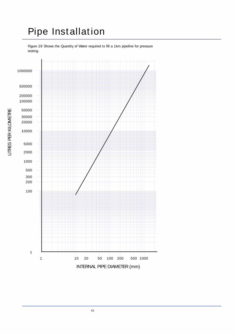
Pipe Installation
43
1000000
10000
2000030000
50000
100000
200000
500000
100
200300
500
1000
2000
5000
1
100010010 20 200 500501
INTERNAL PIPE DIAMETER (mm)
LITR
ES P
ER K
ILO
MET
RE
Figure 29 Shows the Quantity of Water required to fill a 1km pipeline for pressuretesting.
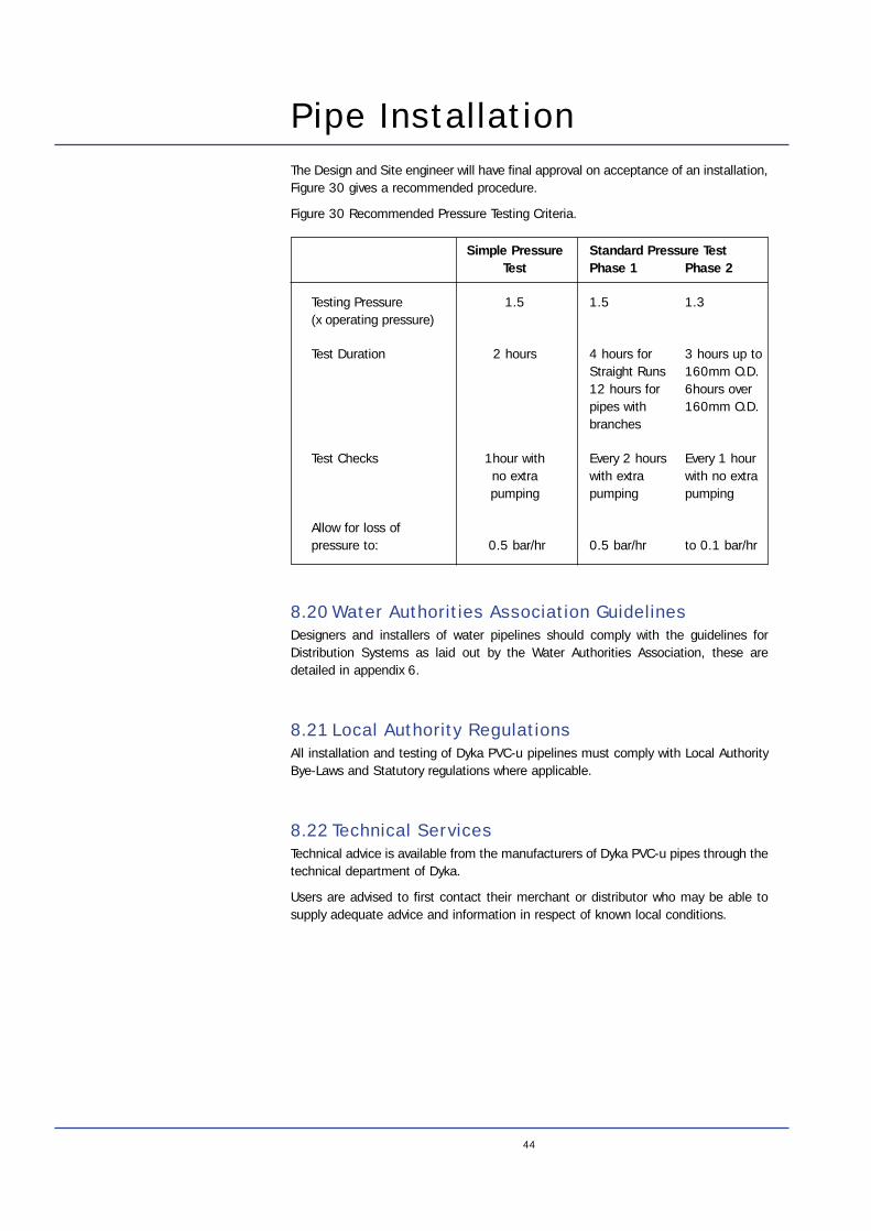
44
Pipe InstallationThe Design and Site engineer will have final approval on acceptance of an installation,Figure 30 gives a recommended procedure.
Figure 30 Recommended Pressure Testing Criteria.
8.20 Water Authorities Association GuidelinesDesigners and installers of water pipelines should comply with the guidelines forDistribution Systems as laid out by the Water Authorities Association, these aredetailed in appendix 6.
8.21 Local Authority RegulationsAll installation and testing of Dyka PVC-u pipelines must comply with Local AuthorityBye-Laws and Statutory regulations where applicable.
8.22 Technical ServicesTechnical advice is available from the manufacturers of Dyka PVC-u pipes through thetechnical department of Dyka.
Users are advised to first contact their merchant or distributor who may be able tosupply adequate advice and information in respect of known local conditions.
Simple Pressure Standard Pressure TestTest Phase 1 Phase 2
Testing Pressure 1.5 1.5 1.3(x operating pressure)
Test Duration 2 hours 4 hours for 3 hours up toStraight Runs 160mm O.D.12 hours for 6hours overpipes with 160mm O.D.branches
Test Checks 1hour with Every 2 hours Every 1 hourno extra with extra with no extrapumping pumping pumping
Allow for loss of pressure to: 0.5 bar/hr 0.5 bar/hr to 0.1 bar/hr
45
Quality Standards Applicable to Dyka PVC-u Pipe
BS3505 Unplasticised polyvinyl chloride (PVC-u) pressure pipes for coldpotable water.
BS3506 Specification for unplasticised PVC pipe for industrial uses.
BS4346 Part 1 Joints and fittings for use with unplasticised PVC pressure pipes. -Solvent Weld
BS4346 Part 2 Joints and fittings for use with unplasticised PVC pressure pipes. -Mechanical Joint
WIS 4.31.06 Specification for blue unplasticised PVC pressure pipes, integraljoints and post-formed bends for cold potable water (undergrounduse).
WIS 4.31.07 Specification for unplasticised PVC pressure fittings andassemblies for cold potable water (underground use).
IGN 4.31.01 Information and guidance note - unplasticised PVC pipes andfittings.
IS 123 Unplasticised PVC pipe for water mains.
SS 1776 Edition 5 Pressure pipes of unplasticised PVC for cold water pipelines.
DS 972 Pressure pipes and fittings of unplasticised polyvinyl chloride forwater supply.
ISO 4422 Pipes and fittings made of unplasticised polyvinyl chloride (PVC-u)for water supply.
ISO 161 Thermoplastic pipes for the transport of fluids - nominal outsidediameters and nominal pressures.
DIN 19582 PVC pressure pipe for water supply.
NEN 7029 PVC-u pipe and couplers for pressure sewer systems.
NEN 7107 Plastic pressure system: Tension proof couplers for PVC-u pipeinstallation and test method.
Appendix 1 - Quality Standards
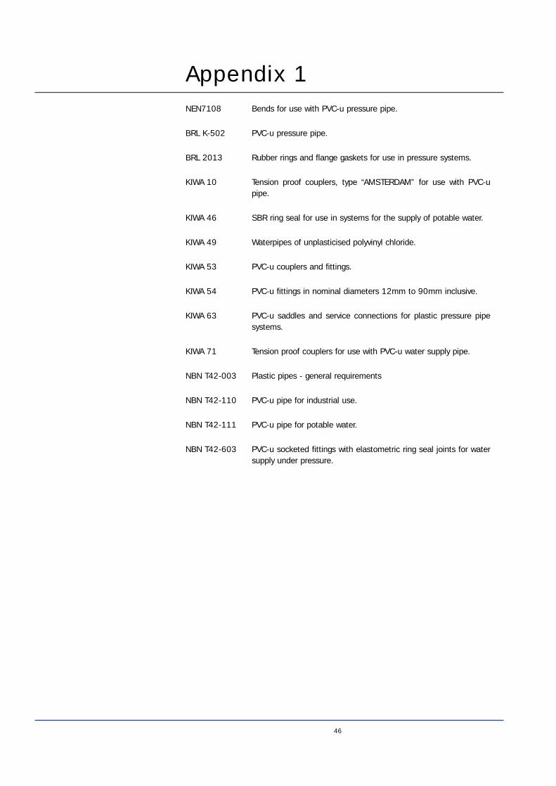
46
Appendix 1NEN7108 Bends for use with PVC-u pressure pipe.
BRL K-502 PVC-u pressure pipe.
BRL 2013 Rubber rings and flange gaskets for use in pressure systems.
KIWA 10 Tension proof couplers, type “AMSTERDAM” for use with PVC-upipe.
KIWA 46 SBR ring seal for use in systems for the supply of potable water.
KIWA 49 Waterpipes of unplasticised polyvinyl chloride.
KIWA 53 PVC-u couplers and fittings.
KIWA 54 PVC-u fittings in nominal diameters 12mm to 90mm inclusive.
KIWA 63 PVC-u saddles and service connections for plastic pressure pipesystems.
KIWA 71 Tension proof couplers for use with PVC-u water supply pipe.
NBN T42-003 Plastic pipes - general requirements
NBN T42-110 PVC-u pipe for industrial use.
NBN T42-111 PVC-u pipe for potable water.
NBN T42-603 PVC-u socketed fittings with elastometric ring seal joints for watersupply under pressure.
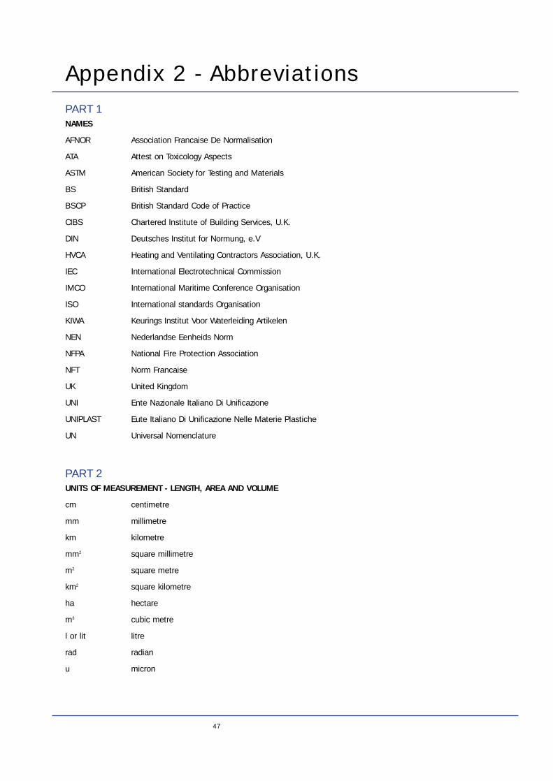
Appendix 2 - Abbreviations
47
PART 1NAMES
AFNOR Association Francaise De Normalisation
ATA Attest on Toxicology Aspects
ASTM American Society for Testing and Materials
BS British Standard
BSCP British Standard Code of Practice
CIBS Chartered Institute of Building Services, U.K.
DIN Deutsches Institut for Normung, e.V
HVCA Heating and Ventilating Contractors Association, U.K.
IEC International Electrotechnical Commission
IMCO International Maritime Conference Organisation
ISO International standards Organisation
KIWA Keurings Institut Voor Waterleiding Artikelen
NEN Nederlandse Eenheids Norm
NFPA National Fire Protection Association
NFT Norm Francaise
UK United Kingdom
UNI Ente Nazionale Italiano Di Unificazione
UNIPLAST Eute Italiano Di Unificazione Nelle Materie Plastiche
UN Universal Nomenclature
PART 2UNITS OF MEASUREMENT - LENGTH, AREA AND VOLUME
cm centimetre
mm millimetre
km kilometre
mm2 square millimetre
m2 square metre
km2 square kilometre
ha hectare
m3 cubic metre
l or lit litre
rad radian
u micron
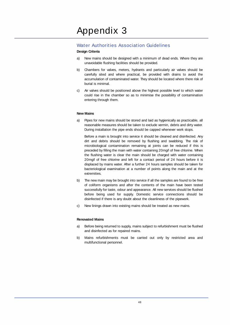
Appendix 3
48
Water Authorities Association GuidelinesDesign Criteria
a) New mains should be designed with a minimum of dead ends. Where they areunavoidable flushing facilities should be provided.
b) Chambers for valves, meters, hydrants and particularly air valves should becarefully sited and where practical, be provided with drains to avoid theaccumulation of contaminated water. They should be located where there risk ofburial is minimal.
c) Air valves should be positioned above the highest possible level to which watercould rise in the chamber so as to minimise the possibility of contaminationentering through them.
New Mains
a) Pipes for new mains should be stored and laid as hygienically as practicable, allreasonable measures should be taken to exclude vermin, debris and dirty water.During installation the pipe ends should be capped whenever work stops.
Before a main is brought into service it should be cleaned and disinfected. Anydirt and debris should be removed by flushing and swabbing. The risk ofmicrobiological contamination remaining at joints can be reduced if this ispreceded by filling the main with water containing 20mg/l of free chlorine. Whenthe flushing water is clear the main should be charged with water containing20mg/l of free chlorine and left for a contact period of 24 hours before it isdisplaced by mains water. After a further 24 hours samples should be taken forbacteriological examination at a number of points along the main and at theextremities.
b) The new main may be brought into service if all the samples are found to be freeof coliform organisms and after the contents of the main have been testedsuccessfully for taste, odour and appearance. All new services should be flushedbefore being used for supply. Domestic service connections should bedisinfected if there is any doubt about the cleanliness of the pipework.
c) New linings drawn into existing mains should be treated as new mains.
Renovated Mains
a) Before being returned to supply, mains subject to refurbishment must be flushedand disinfected as for repaired mains.
b) Mains refurbishments must be carried out only by restricted area andmultifunctional personnel.
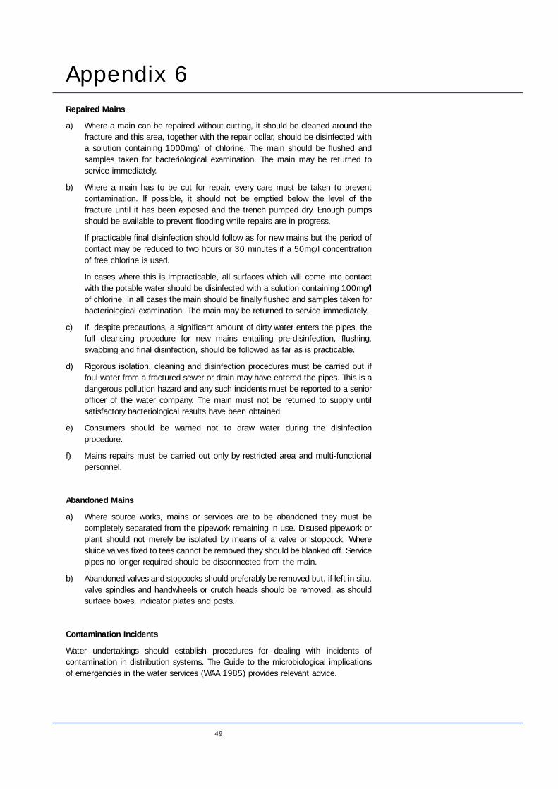
49
Repaired Mains
a) Where a main can be repaired without cutting, it should be cleaned around thefracture and this area, together with the repair collar, should be disinfected witha solution containing 1000mg/l of chlorine. The main should be flushed andsamples taken for bacteriological examination. The main may be returned toservice immediately.
b) Where a main has to be cut for repair, every care must be taken to preventcontamination. If possible, it should not be emptied below the level of thefracture until it has been exposed and the trench pumped dry. Enough pumpsshould be available to prevent flooding while repairs are in progress.
If practicable final disinfection should follow as for new mains but the period ofcontact may be reduced to two hours or 30 minutes if a 50mg/l concentrationof free chlorine is used.
In cases where this is impracticable, all surfaces which will come into contactwith the potable water should be disinfected with a solution containing 100mg/lof chlorine. In all cases the main should be finally flushed and samples taken forbacteriological examination. The main may be returned to service immediately.
c) If, despite precautions, a significant amount of dirty water enters the pipes, thefull cleansing procedure for new mains entailing pre-disinfection, flushing,swabbing and final disinfection, should be followed as far as is practicable.
d) Rigorous isolation, cleaning and disinfection procedures must be carried out iffoul water from a fractured sewer or drain may have entered the pipes. This is adangerous pollution hazard and any such incidents must be reported to a seniorofficer of the water company. The main must not be returned to supply untilsatisfactory bacteriological results have been obtained.
e) Consumers should be warned not to draw water during the disinfectionprocedure.
f) Mains repairs must be carried out only by restricted area and multi-functionalpersonnel.
Abandoned Mains
a) Where source works, mains or services are to be abandoned they must becompletely separated from the pipework remaining in use. Disused pipework orplant should not merely be isolated by means of a valve or stopcock. Wheresluice valves fixed to tees cannot be removed they should be blanked off. Servicepipes no longer required should be disconnected from the main.
b) Abandoned valves and stopcocks should preferably be removed but, if left in situ,valve spindles and handwheels or crutch heads should be removed, as shouldsurface boxes, indicator plates and posts.
Contamination Incidents
Water undertakings should establish procedures for dealing with incidents ofcontamination in distribution systems. The Guide to the microbiological implicationsof emergencies in the water services (WAA 1985) provides relevant advice.
Appendix 6

50

51

52


![Wireless Sensornetworks Concepts, Protocolls and Applications Zoya Dyka/Peter Langendörfer e-mail: dyka [ at ] ihp-microelectronics.com web: .](https://static.fdocuments.in/doc/165x107/55204d7d49795902118ccf88/wireless-sensornetworks-concepts-protocolls-and-applications-zoya-dykapeter-langendoerfer-e-mail-dyka-at-ihp-microelectronicscom-web-wwwtu-cottbusdesysteme.jpg)