DXS-1210 Series CLI Reference Guide
385
Transcript of DXS-1210 Series CLI Reference Guide
DXS-1210 Series
CLI Reference GuideL2 10 Gigabit Ethernet Switch SeriesVer. 1.01

DXS-1210 Series Smart Managed Switch CLI Reference Guide
ii
Table of Contents Table of Contents .............................................................................................................................................................. ii
1. Introduction ............................................................................................................................................................. 1
2. Basic CLI Commands ........................................................................................................................................... 10
3. 802.1X Commands ............................................................................................................................................... 20
4. Access Control List (ACL) Commands ................................................................................................................. 33
5. Access Management Commands ........................................................................................................................ 54
6. Asymmetric VLAN Commands ............................................................................................................................. 71
7. Authentication, Authorization, and Accounting (AAA) Commands ...................................................................... 73
8. Basic IPv4 Commands ......................................................................................................................................... 81
9. Basic IPv6 Commands ......................................................................................................................................... 87
10. Cable Diagnostics Commands ............................................................................................................................. 94
11. Debug Commands ............................................................................................................................................... 97
12. DHCP Client Commands...................................................................................................................................... 99
13. DHCPv6 Client Commands ................................................................................................................................ 104
14. D-Link Discovery Protocol (DDP) Client Commands ......................................................................................... 105
15. DoS Prevention Commands ............................................................................................................................... 108
16. Error Recovery Commands ................................................................................................................................ 112
17. Ethernet Ring Protection Switching (ERPS) Commands ................................................................................... 116
18. Filter Database (FDB) Commands ..................................................................................................................... 128
19. IGMP Snooping Commands .............................................................................................................................. 136
20. Interface Commands .......................................................................................................................................... 148
21. IP Utility Commands ........................................................................................................................................... 159
22. Jumbo Frame Commands .................................................................................................................................. 161
23. Link Aggregation Control Protocol (LACP) Commands ..................................................................................... 162
24. Link Layer Discovery Protocol (LLDP) Commands ............................................................................................ 167
25. Loopback Detection (LBD) Commands .............................................................................................................. 194
26. Mirror Commands ............................................................................................................................................... 201
27. MLD Snooping Commands ................................................................................................................................ 204
28. Multiple Spanning Tree Protocol (MSTP) Commands ....................................................................................... 216
29. Network Access Authentication Commands ...................................................................................................... 225
30. Port Security Commands ................................................................................................................................... 235
31. Power Saving Commands .................................................................................................................................. 243
32. Protocol Independent Commands ...................................................................................................................... 249
33. Quality of Service (QoS) Commands ................................................................................................................. 255
34. Remote Network MONitoring (RMON) Commands ........................................................................................... 267
35. Safeguard Engine Commands ........................................................................................................................... 275
36. Secure Sockets Layer (SSL) Commands .......................................................................................................... 277
37. Simple Network Management Protocol (SNMP) Commands ............................................................................ 280
38. Spanning Tree Protocol (STP) Commands........................................................................................................ 298
39. Storm Control Commands .................................................................................................................................. 310

DXS-1210 Series Smart Managed Switch CLI Reference Guide
iii
40. Surveillance VLAN Commands .......................................................................................................................... 315
41. Switch Port Commands ...................................................................................................................................... 321
42. System File Management Commands ............................................................................................................... 324
43. System Log Commands ..................................................................................................................................... 332
44. Time and SNTP Commands .............................................................................................................................. 337
45. Time Range Commands .................................................................................................................................... 343
46. Traffic Segmentation Commands ....................................................................................................................... 346
47. Virtual LAN (VLAN) Commands ......................................................................................................................... 348
48. Voice VLAN Commands..................................................................................................................................... 358
Appendix A - System Log Entries ................................................................................................................................. 365
Appendix B - Trap Entries ............................................................................................................................................. 373
Appendix C - RADIUS Attributes Assignment ............................................................................................................... 379
Appendix D - IETF RADIUS Attributes Support ............................................................................................................ 381
Appendix E - ERPS Information .................................................................................................................................... 382
DXS-1210 Series Smart Managed Switch CLI Reference Guide
1
1. Introduction This manual’s command descriptions are based on the software release 1.15. The commands listed here are the subset of commands that are supported by the DXS-1210 Series Smart Managed Switch.
Audience This CLI Reference Guide is intended for network administrators and other IT networking professionals responsible for managing the switch by using the Command Line Interface (CLI). The CLI is the primary management interface to the DXS-1210 Series Smart Managed Switch, which will be generally be referred to simply as “the Switch” within this manual. This manual is written in a way that assumes that you already have the experience and knowledge of Ethernet and modern networking principles for Local Area Networks.
Other Documentation The documents below are a further source of information in regards to configuring and troubleshooting the Switch. All the documents are available from the CD bundled with this switch, or from the D-Link website. Other documents related to the Switch are:
• DXS-1210 Series Smart Managed Switch Web UI Reference Guide
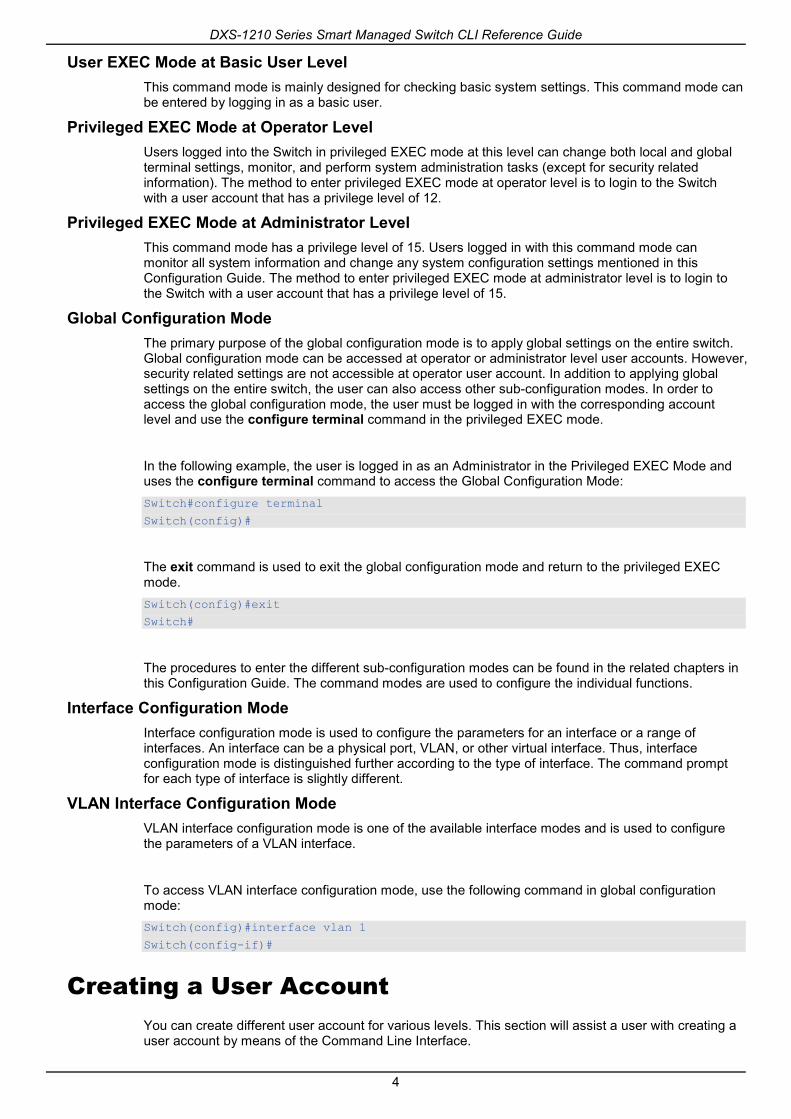
Conventions
Convention Description
Boldface Font Commands, command options and keywords are printed in boldface. Keywords, in the command line, are to be entered exactly as they are displayed.
UPPERCASE ITALICS Font Parameters or values that must be specified are printed in UPPERCASE ITALICS. Parameters in the command lineare to be replaced with the actual values that are desired to be used with the command.
Square Brackets [ ] Square brackets enclose an optional value or set of optional arguments.
Braces { } Braces enclose alternative keywords separated by vertical bars. Generally, one of the keywords in the separated list can be chosen.
Vertical Bar | Optional values or arguments are enclosed in square brackets and separated by vertical bars. Generally, one or more of the vales or arguments in the separated list can be chosen.
Blue Courier Font This convention is used to represent an example of a screen console display including example entries of CLI command input with the corresponding output. All examples used in this manual are based on the DXS-1210-28P switch.
Notes, Notices, and Cautions Below are examples of the three types of indicators used in this manual. When administering your switch using the information in this document, you should pay special attention to these indicators. Each example below provides an explanatory remark regarding each type of indicator.

DXS-1210 Series Smart Managed Switch CLI Reference Guide
2
NOTE: A note indicates important information that helps you make better use of your device.
NOTICE: A notice indicates either potential damage to hardware or loss of data and tells you how to avoid the problem.
CAUTION: A caution indicates a potential for property damage, personal injury, or death.
Command Descriptions The information pertaining to each command in this reference guide is presented using a number of template fields. The fields are:
• Description - This is a short and concise statement describing the commands functionality.
• Syntax - The precise form to use when entering and issuing the command.
• Parameters - A table where each row describes the optional or required parameters, and their use, that can be issued with the command.
• Default - If the command sets a configuration value or administrative state of the Switch then any default settings (i.e. without issuing the command) of the configuration is shown here.
• Command Mode - The mode in which the command can be issued. These modes are described in the section titled “Command Modes” below.
• Command Default Level – The user privilege level in which the command can be issued.
• Usage Guideline - If necessary, a detailed description of the command and its various utilization scenarios is given here.
• Example(s) - Each command is accompanied by a practical example of the command being issued in a suitable scenario.
Command Modes There are several command modes available in the command-line interface (CLI). The set of commands available to the user depends on both the mode the user is currently in and their privilege level. For each case, the user can see all the commands that are available in a particular command mode by entering a question mark (?) at the system prompt.
The command-line interface has threepre-defined privilege levels:
• Basic User - Privilege Level 1. This user account level has the lowest priority of the user accounts. The purpose of this type of user account level is for basic system checking.
• Operator - Privilege Level 12. This user account level is used to grant system configuration rights for users who need to change or monitor system configuration, except for security related information such as user accounts and SNMP account settings, etc.
• Administrator - Privilege Level 15. This administrator user account level can monitor all system information and change any of the system configuration settings expressed in this configuration guide.
The command-line interface has a number of command modes. There are three basic command modes:

DXS-1210 Series Smart Managed Switch CLI Reference Guide
3
• User EXEC Mode
• Privileged EXEC Mode
• Global Configuration Mode
All other sub-configuration modes can be accessed via the Global Configuration Mode.
When a user logs in to the Switch, the privilege level of the user determines the command mode the user will enter after initially logging in. The user will either log into User EXEC Mode or the Privileged EXEC Mode.
• Users with a basic user level will log into the Switch in the User EXEC Mode.
• Users with operator or administrator level accounts will log into the Switch in the Privileged EXEC Mode.
Therefore, the User EXEC Mode can operate at a basic user level and the Privileged EXEC Mode can operate at the operator, or administrator levels. The user can only enter the Global Configuration Mode from the Privileged EXEC Mode. The Global Configuration Mode can be accessed by users who have operator or administrator level user accounts.
As for sub-configuration modes, a subset of those can only be accessed by users who have the highest secure administrator level privileges.
The following table briefly lists the available command modes. Only the basic command modes and some of the sub-configuration modes are enumerated. The basic command modes and basic sub-configuration modes are further described in the following chapters. Descriptions for the rest of the sub-configuration modes are not provided in this section. For more information on the additional sub-configuration modes, the user should refer to the chapters relating to these functions.
The available command modes and privilege levels are described below:
Command Mode/
Privilege Level
Purpose
User EXEC Mode / Basic User level
This level has the lowest priority of the user accounts. It is provided only to check basic system settings.
Privileged EXEC Mode / Operator level
For changing both local and global terminal settings, monitoring, and performing certain system administration tasks. The system administration tasks that can be performed at this level except for any security related information.
Privileged EXEC Mode / Administrator level
This level is identical to privileged EXEC mode at the operator level, except that a user at the administrator level can monitor and clear security related settings.
Global Configuration Mode / Operator level
For applying global settings, except for security related settings, on the entire switch. In addition to applying global settings on the entire switch, the user can access other sub-configuration modes from global configuration mode.
Global Configuration Mode / Administrator level
For applying global settings on the entire switch. In addition to applying global settings on the entire switch, the user can access other sub-configuration modes from global configuration mode.
Interface Configuration Mode /Administrator level
For applying interface related settings.
VLAN Interface Configuration Mode
For applying VLAN interface related settings.
DXS-1210 Series Smart Managed Switch CLI Reference Guide
4
User EXEC Mode at Basic User Level This command mode is mainly designed for checking basic system settings. This command mode can be entered by logging in as a basic user.
Privileged EXEC Mode at Operator Level Users logged into the Switch in privileged EXEC mode at this level can change both local and global terminal settings, monitor, and perform system administration tasks (except for security related information). The method to enter privileged EXEC mode at operator level is to login to the Switch with a user account that has a privilege level of 12.
Privileged EXEC Mode at Administrator Level This command mode has a privilege level of 15. Users logged in with this command mode can monitor all system information and change any system configuration settings mentioned in this Configuration Guide. The method to enter privileged EXEC mode at administrator level is to login to the Switch with a user account that has a privilege level of 15.
Global Configuration Mode The primary purpose of the global configuration mode is to apply global settings on the entire switch. Global configuration mode can be accessed at operator or administrator level user accounts. However, security related settings are not accessible at operator user account. In addition to applying global settings on the entire switch, the user can also access other sub-configuration modes. In order to access the global configuration mode, the user must be logged in with the corresponding account level and use the configure terminal command in the privileged EXEC mode.
In the following example, the user is logged in as an Administrator in the Privileged EXEC Mode and uses the configure terminal command to access the Global Configuration Mode: Switch#configure terminal
Switch(config)#
The exit command is used to exit the global configuration mode and return to the privileged EXEC mode. Switch(config)#exit
Switch#
The procedures to enter the different sub-configuration modes can be found in the related chapters in this Configuration Guide. The command modes are used to configure the individual functions.
Interface Configuration Mode Interface configuration mode is used to configure the parameters for an interface or a range of interfaces. An interface can be a physical port, VLAN, or other virtual interface. Thus, interface configuration mode is distinguished further according to the type of interface. The command prompt for each type of interface is slightly different.
VLAN Interface Configuration Mode VLAN interface configuration mode is one of the available interface modes and is used to configure the parameters of a VLAN interface.
To access VLAN interface configuration mode, use the following command in global configuration mode: Switch(config)#interface vlan 1
Switch(config-if)#
Creating a User Account You can create different user account for various levels. This section will assist a user with creating a user account by means of the Command Line Interface.

DXS-1210 Series Smart Managed Switch CLI Reference Guide
5
NOTE: By default, one user account is already configured on the Switch. Both the username and password for this account is admin, and the privilege level is 15.
Observe the following example. Switch>enable
Switch#configure terminal
Switch(config)#username user1 privilege 15 password 0 pass1234
Switch(config)#line console
Switch(config-line)#
In the above example we had to navigate and access the username command.
• Starting in the User EXEC Mode we enter the command enable to access the Privileged EXEC Mode.
• After accessing the Privileged EXEC Mode, we entered the command configure terminal to access the Global Configuration Mode.The username command can be used in the Global Configuration Mode.
• The command username user1 privilege 15 password 0 pass1234 creates a user account with the username of user1 and a password of pass1234, and assigns a privilege level value of 15 to the user.
• The command line console allows us to access the console interface’s Line Configuration Mode.
Save the running configuration to the start-up configuration. This means to save the changes made so that when the Switch is rebooted, the configuration will not be lost. The following example shows how to save the running configuration to the start-up configuration. Switch#copy running-config startup-config
Destination filename startup-config? [y/n]: y
Saving all configurations to NV-RAM.......... Done.
Switch#
After the Switch was rebooted, or when the users logs out and back in, the newly created username and password must be entered to access the CLI interface again, as seen below. DXS-1210-12SC 10GbE Smart Managed Switch
Command Line Interface
Firmware: Build V1.15.005
Copyright(C) 2017 D-Link Corporation. All rights reserved.
User Access Verification
Username: admin
Password: *****
Switch#

DXS-1210 Series Smart Managed Switch CLI Reference Guide
6
Interface Notation When configuration the physical ports available on this switch, a specific interface notation is used. The following will explain the layout, terminology and use of this notation.
In the following example, we will enter the Global Configuration Mode and then enter the Interface Configuration Mode, using the notation 1/0/1. After entering the Interface Configuration Mode for port 1, we will change the speed to 1 Gbps, using the speed 1000 command. Switch# configure terminal
Switch(config)# interface Ethernet 1/0/1
Switch(config-if)# speed 1000
Switch(config-if)#
In the above example the notation 1/0/1 was used. The terminology for each parameter is as follows:
• Interface Unit’s ID / Open Slot’s ID / Port’s ID
The Interface Unit’s ID is the ID of the stacking unit without the physical stack. If stacking is disabled or this unit is a stand-alone unit, then this parameter is irrelevant. The Open Slot’s ID is the ID of the module plugged into the open module slot of the Switch. The DXS-1210 Series does not support any open modules slots, thus this parameters will always by zero for this switch series. Lastly, the Port’s ID is the physical port number of the port being configured.
In summary the above example will configure the stacked switch with the ID of 1, with the open slot ID of 0, and the physical port number 1.
Error Messages When the users issue a command that the Switch does not recognize, error messages will be generated to assist users with basic information about the mistake that was made. A list of possible error messages are found in the table below.
Error Message Meaning
Ambiguous command Not enough keywords were entered for the Switch to recognize the command.
Incomplete command The command was not entered with all the required keyword.
Invalid input detected at ^marker
The command was entered incorrectly.
The following example shows how an ambiguous command error message is generated. Switch# show v
Ambiguous command
Switch#
The following example shows how an incomplete command error message is generated. Switch# show
Incomplete command
Switch#
The following example shows how an invalid input error message is generated.

DXS-1210 Series Smart Managed Switch CLI Reference Guide
7
Switch# show verb
^
Invalid input detected at ^marker
Switch#
Editing Features The command line interface of this switch supports to following keyboard keystroke editing features.
Keystroke Description
Delete Deletesthe character under the cursor and shifts the remainder of the line to the left.
Backspace Deletesthe character to the left of the cursor and shifts the remainder of the line to the left.
Left Arrow Movesthe cursor to the left.
Right Arrow Moves the cursor to the right.
CTRL+R Togglesthe insert text function on and off. When on, text can be inserted in the line and the remainder of the text will be shifted to the right. When off, text can be inserted in the line and old text will automatically be replaced with the new text.
Return Scrolls down to display the next line or used to issue a command.
Space Scrolls down to display the next page.
ESC Escapes from the displaying page.
Display Result Output Modifiers Results displayed by show commands can be filtered using the following parameters:
• beginFILTER-STRING - This parameter is used to start the display with the first line that matches the filter string.
• includeFILTER-STRING - This parameter is used to display all the lines that match the filter string.
• excludeFILTER-STRING - This parameter is used to exclude the lines that match the filter string from the display.
The example below shows how to use the beginFILTER-STRING parameter in a show command.

DXS-1210 Series Smart Managed Switch CLI Reference Guide
8
Switch# show running-config begin # AAA
#------------------------------------------------------------------------
# DXS-1210-12SC 10GbE Smart Managed Switch Configuration
#
# Firmware: Build V1.15.005
# Copyright(C) 2017 D-Link Corporation. All rights reserved.
#------------------------------------------------------------------------
# AAA
end
configure terminal
no aaa new-model
end
# Dot1x
end
configure terminal
no dot1x system-auth-control
no snmp-server enable traps dot1x
interface ethernet 1/0/1
no dot1x pae authenticator
dot1x control-direction both
dot1x forward-pdu
dot1x max-req 2
dot1x timeout server-timeout 30
dot1x timeout supp-timeout 30
CTRL+C ESC q Quit SPACE n Next PageENTER Next Entry a All
The example below shows how to use the includeFILTER-STRING parameter in a show command. Switch# show running-config include # AAA
#------------------------------------------------------------------------
# DXS-1210-12SC 10GbE Smart Managed Switch Configuration
#
# Firmware: Build V1.15.005
# Copyright(C) 2017 D-Link Corporation. All rights reserved.
#------------------------------------------------------------------------
# AAA
Switch#
The example below shows how to use the excludeFILTER-STRING parameter in a show command.

DXS-1210 Series Smart Managed Switch CLI Reference Guide
9
Switch# show running-config exclude # AAA
#------------------------------------------------------------------------
# DXS-1210-12SC 10GbE Smart Managed Switch Configuration
#
# Firmware: Build V1.15.005
# Copyright(C) 2017 D-Link Corporation. All rights reserved.
#------------------------------------------------------------------------
# Basic
# LACP
configure terminal
lacp system-priority 32768
port-channel load-balance src-dst-mac
interface ethernet 1/0/1
lacp port-priority 32768
lacp timeout short
exit
interface ethernet 1/0/2
lacp port-priority 32768
lacp timeout short
exit
interface ethernet 1/0/3
lacp port-priority 32768
lacp timeout short
exit
CTRL+C ESC q Quit SPACE n Next PageENTER Next Entry a All

DXS-1210 Series Smart Managed Switch CLI Reference Guide
10
2. Basic CLI Commands 2-1 help
This command is used to display a brief description of the help system.Use the help command in any command mode.
help
Parameters None.
Default None.
Command Mode EXEC Mode or Any Configuration Mode.
Command Default Level Level: 1.
Usage Guideline The help command provides a brief description for the help system, which includes the following functions:
• To list all commands available for a particular command mode, enter a question mark (?) at the system prompt.
• To obtain a list of commands that begin with a particular character string, enter the abbreviated command entry immediately followed by a question mark (?). This form of help is called word help, because it lists only the keywords or arguments that begin with the abbreviation entered.
• To list the keywords and arguments associated with a command, enter a question mark (?) in place of a keyword or argument on the command line. This form of help is called the command syntax help, because it lists the keywords or arguments that apply based on the command, keywords, and arguments already entered.
Example This example shows how the help command is used to display a brief description of the help system.

DXS-1210 Series Smart Managed Switch CLI Reference Guide
11
Switch#help
The switch CLI provides advanced help feature.
1. Help is available when you are ready to enter a command
argument (e.g. 'show ?') and want to know each possible
available options.
2. Help is provided when an abbreviated argument is entered
and you want to know what arguments match the input(e.g. 'show ve?'.).
If nothing matches, the help list will be empty and you must backup
until entering a '?' shows the available options.
3. For completing a partial command name could enter the abbreviated
command name immediately followed by a <Tab> key.
Note:
Since the character '?' is used for help purpose, to enter
the character '?' in a string argument, press ctrl+v immediately
followed by the character '?'.
Switch#
The following example shows how to use the word help to display all the Privileged EXEC Mode commands that begin with the letters “re”. The letters entered before the question mark (?) are reprinted on the next command line to allow the user to continue entering the command. Switch#re?
reboot reset
Switch#re
The following example shows how to use the command syntax help to display the next argument of a partially complete IP access-list standard command. The characters entered before the question mark (?) is reprinted on the next command line to allow the user to continue entering the command. Switch(config)#ip access-list standard ?
<1-1999> Standard IP access-list number
<cr>
Switch(config)#ip access-list standard
2-2 configure terminal This command is used to enter the Global Configuration Mode.
configure terminal
Parameters None.
Default None
Command Mode User EXEC Mode or Privilege EXEC Mode.
Command Default Level

DXS-1210 Series Smart Managed Switch CLI Reference Guide
12
Level: 12.
Usage Guideline This command is used to enter the Global Configuration Mode.
Example This example shows how to enter into Global Configuration Mode. Switch# configure terminal
Switch(config)#
2-3 logout This command is used to close an active terminal session by logging off the Switch.
logout
Parameters None.
Default None.
Command Mode User EXEC Mode.
Privilege EXEC Mode.
Command Default Level Level:1.
Usage Guideline Use this command to close an active terminal session by logging out of the device.
Example This example shows how to logout Switch# disable
Switch# logout
2-4 end This command is used to end the current configuration mode and return to the highest mode in the CLI mode hierarchy which is either the User EXEC Mode or the Privileged EXEC Mode.
end
Parameters None.
Default None.
Command Mode

DXS-1210 Series Smart Managed Switch CLI Reference Guide
13
EXEC Mode or Any Configuration Mode.
Command Default Level Level: 1.
Usage Guideline Executing this command will return access to the highest mode in the CLI hierarchy regardless of what configuration mode or configuration sub-mode currently located at.
Example This example shows how to end the Interface Configuration Mode and go back to the Privileged EXEC Mode. Switch# configure terminal
Switch(config)# interface eth 1/0/1
Switch(config-if)#end
Switch#
2-5 exit This command is used to end the configuration mode and go back to the last mode. If the current mode is the User EXEC Mode or the Privilege EXEC Mode, executing the exit command logs you out of the current session.
exit
Parameters None.
Default None.
Command Mode EXEC Mode or Any Configuration Mode.
Command Default Level Level: 1.
Usage Guideline Use this command to exit the current configuration mode and go back to the last mode. When the user is in the User EXEC Mode or the Privilege EXEC Mode, this command will logout the session.
Example This example shows how to exit from the Interface Configuration Mode and return to the Global Configuration Mode. Switch# configure terminal
Switch(config)interface eth 1/0/1
Switch(config-if)#exit
Switch(config)#
2-6 show history This command is used to list the commands entered in the current EXEC Mode session.

DXS-1210 Series Smart Managed Switch CLI Reference Guide
14
show history
Parameters None.
Default None.
Command Mode EXEC Mode or Any Configuration Mode.
Command Default Level Level: 1.
Usage Guideline Commands entered are recorded by the system. A recorded command can be recalled by pressing CTRL+P or the Up Arrow key which will recall previous commands in sequence. The history buffer size is fixed at 20 commands.
The function key instructions, below, displays how to navigate the command in the history buffer.
• CTRL+P or the Up Arrow key - Recalls commands in the history buffer, beginning with the most recent command. Repeat the key sequence to recall successively older commands.
• CTRL+N or the Down Arrow key - Returns to more recent commands in the history buffer after recalling commands with Ctrl-P or the Up Arrow key. Repeat the key sequence to recall successively more recent commands.
Example This example shows how to display the command buffer history. Switch# show history
help
history
Switch#
2-7 show environment This command is used to display fan, temperature, power availability and status information.
show environment [fan | temperature]
Parameters
fan (Optional) Specifies to display the Switch fan detailed status.
temperature (Optional) Specifies to display the Switch temperature detailed status.
Default None.
Command Mode EXEC Mode or Any Configuration Mode.
Command Default Level Level: 1.

DXS-1210 Series Smart Managed Switch CLI Reference Guide
15
Usage Guideline If the type is not specified, all types of environment information will be displayed.
Example This example shows how to display fan, temperature, power availability and status information. Switch#show environment
Detail Temperature Status:
Temperature Descr/ID Current/Threshold Range
------------------------------------------------------
Central Temperature/1 27C/11~79C
Status code: * temperature is out of threshold range
Detail Fan Status:
--------------------------------------------------------------
Right Fan 1 (OK) Right Fan 2 (OK)
Switch#
2-8 show unit This command is used to display information about system units.
show unit
Parameters
UNIT-ID (Optional) Specify the unit to display.
Default None.
Command Mode EXEC Mode or Any Configuration Mode.
Command Default Level Level: 1.
Usage Guideline This command displays information about the system modules. If no option is specified, then all of units’ information will be displayed.
Example This example shows how to display the information about units on a system.

DXS-1210 Series Smart Managed Switch CLI Reference Guide
16
Switch#show unit
Model Descr Model Name
------------------------------------------- ------------------
No module description DXS-1210-12SC
Serial-Number Status Up Time
--------------------------------- --------- -----------------
ok 0DT6H32M18S
Memory Total Used Free
-------- ---------- ---------- ----------
DRAM 131072 K 66567 K 64505 K
FLASH 29937 K 7799 K 22138 K
Switch#
2-9 show cpu utilization This command is used to display the CPU utilization information.
show cpu utilization
Parameters None.
Default None.
Command Mode EXEC Mode or Any Configuration Mode.
Command Default Level Level: 1.
Usage Guideline This command displays the system’s CPU utilization information in 5second, 1minute, and 5 minute intervals.
Example This example shows how to display the information about CPU utilization. Switch#show cpu utilization
CPU Utilization
Five seconds - 8 % One minute - 7 % Five minutes - 7 %
Switch#
2-10 show version This command is used to display the Switch’s software version information.

DXS-1210 Series Smart Managed Switch CLI Reference Guide
17
show version
Parameters None.
Default None.
Command Mode EXEC Mode or Any Configuration Mode.
Command Default Level Level: 1.
Usage Guideline This command displays version information about the Switch.
Example This example shows how to displays version information about the Switch. Switch#show version
System MAC Address: 3C-1E-04-A1-CC-00
Module Name Versions
------------------ ---------------------
DXS-1210-12SC H/W:A2
Bootloader:1.00.006
Runtime:1.15.005
Switch#
2-11 snmp-server enable traps environment This command is used to enable the power, temperature and fan trap state.
snmp-server enable traps environment [fan] [temperature]
no snmp-server enable traps environment [fan] [temperature]
Parameters
fan (Optional) Specifies to enable the fan trap state for warning fan event (fan failed or fan recover).
temperature (Optional) Specifies to enable the temperature trap state for warning temperature event (temperatureexceeds the thresholds or temperaturerecover).
Default None.
Command Mode Global Configuration Mode.

DXS-1210 Series Smart Managed Switch CLI Reference Guide
18
Command Default Level Level: 12.
Usage Guideline This command is used to configure the environment temperature threshold which corresponds to the normal range of the temperature defined for the sensor. The low threshold must be smaller than the high threshold. The configured range must fall within the operational range which corresponds to the minimum and maximum allowed temperatures defined for the sensor. When the configured threshold is crossed, a notification will be sent.
Example This example shows how to configure the environment temperature thresholds for thermal sensor ID 1 on unit 1. Switch# configure terminal
Switch(config)# environment temperature threshold low 20
Switch(config)# environment temperature threshold high 100
2-12 environment temperature threshold This command is used to configure the environment temperature thresholds. Use the no form of this command to revert to the default setting.
environment temperature threshold { low | high } <negative>
no environment temperature threshold { low | high } <negative>
Parameters
high (Optional) Specifies the high threshold of the temperature in Celsius. The range is from -100 to 200.
low (Optional) Specifies the low threshold of the temperature in Celsius. The range is from -100 to 200. The low threshold must be smaller than the high threshold.
Default None.
Command Mode Global Configuration Mode.
Command Default Level Level: 12.
Usage Guideline This command is used to configure the environment temperature threshold which corresponds to the normal range of the temperature defined for the sensor. The low threshold must be smaller than the high threshold. The configured range must fall within the operational range which corresponds to the minimum and maximum allowed temperatures defined for the sensor. When the configured threshold is crossed, a notification will be sent.
Example This example shows how to configure the environment temperature thresholds for thermal sensor ID 1 on unit 1.

DXS-1210 Series Smart Managed Switch CLI Reference Guide
19
Switch# configure terminal
Switch(config)# environment temperature threshold low 20
Switch(config)# environment temperature threshold high 100
2-13 show privilege This command is used to display current privilege level.
show privilege
Parameters None.
Default None.
Command Mode EXEC Mode or Any Configuration Mode.
Command Default Level Level: 1.
Usage Guideline This command is used to display current privilege level.
Example This example shows how to display the current privilege level. Switch# Switch#show privilege
Current privilege level is 15
Switch#

DXS-1210 Series Smart Managed Switch CLI Reference Guide
20
3. 802.1X Commands 3-1 clear dot1x counters
This command is used to clear 802.1X counters (diagnostics, statistics and session statistics).
clear dot1x counters {all | interface INTERFACE-ID [, | -]}
Parameters
all Specifies to clear 802.1X counters (diagnostics, statistics and session statistics) on all interfaces.
interface INTERFACE-ID Specifies to clear 802.1X counters (diagnostics, statistics and session statistics) on the specified interface. Valid interfaces are physical ports (including type, stack member, and port number).
, (Optional) Specifies a series of interfaces, or separate a range of interfaces from a previous range. No space is allowed before and after the comma.
- (Optional) Specifies a range of interfaces. No space is allowed before and after the hyphen.
Default None.
Command Mode Privileged EXEC Mode.
Command Default Level Level: 12.
Usage Guideline This command is used to clear 802.1X counters (diagnostics, statistics and session statistics).
Example This example shows how to clear 802.1X counters (diagnostics, statistics and session statistics) on the Ethernet port 1/0/1. Switch# clear dot1x counters interface eth 1/0/1
Switch#
3-2 dot1x control-direction This command is used to configure the direction of the traffic on a controlled port bidirectional (both). Use the no form of this command to revert to the default setting.
dot1x control-direction {both}
no dot1x control-direction
Parameters
both Specifies to enable bidirectional control for the port.
Default

DXS-1210 Series Smart Managed Switch CLI Reference Guide
21
By default, this option is bidirectional mode.
Command Mode Interface Configuration Mode.
Command Default Level Level: 12.
Usage Guideline This command is only available for physical port interface configuration. If the port control is set to force-authorized, then the port is not controlled in both directions. If the port control is set to auto, then the access to the port for the controlled direction needs to be authenticated. If the port control is set to force-unauthorized, then the access to the port for the controlled direction is blocked.
Suppose that port control is set to auto. If the control direction is set to both, then the port can receive and transmit EAPOL packets only. All user traffic is blocked before authentication.
Example This example shows how to configure the controlled direction of the traffic through Ethernet eth1/0/1 as unidirectional. Switch# configure terminal
Switch(config)#interface eth 1/0/1
Switch(config-if)# dot1x control-direction both
Switch(config-if)#
3-3 dot1x default This command is used to reset the IEEE 802.1X parameters on a specific port to their default settings.
dot1x default
Parameters None.
Default IEEE 802.1X authentication is disabled.
Control direction is bidirectional (both).
Port control is auto.
Forward PDU on port is enabled.
Maximum request is 2 times.
Server timer is 30 seconds.
Supplicant timer is 30 seconds.
Transmit interval is 30 seconds.
Command Mode Interface Configuration Mode.
Command Default Level Level: 12.
Usage Guideline This command is used to reset all the IEEE 802.1X parameters on a specific port to their default settings.
Example

DXS-1210 Series Smart Managed Switch CLI Reference Guide
22
This example shows how to reset the 802.1X parameters on port 1/0/1. Switch# configure terminal
Switch(config)#interface eth 1/0/1
Switch(config-if)# dot1x default
Switch(config-if)#
3-4 dot1x port-control This command is used to control the authorization state of a port. Use the no form of this command to revert to the default setting.
dot1x port-control {auto | force-authorized | force-unauthorized}
no dot1x port-control
Parameters
auto Specifies to enable IEEE 802.1X authentication for the port.
force-authorized Specifies the port to the force authorized state.
force-unauthorized Specifies the port to the force unauthorized state.
Default By default, this option is set as auto.
Command Mode Interface Configuration Mode.
Command Default Level Level: 12.
Usage Guideline This command takes effect only when IEEE 802.1X PAE authenticator is globally enabled by the dot1x system-auth-control command and is enabled for a specific port by using the dot1x PAE authenticator.
This command is only available for physical port interface configuration.
If the port control is set to force-authorized, then the port is not controlled in both directions. If the port control is set to auto, then the access to the port for the controlled direction needs to be authenticated. If the port control is set to force-unauthorized, then the access to the port for the controlled direction is blocked.
Example This example shows how to deny all access on Ethernet port 1/0/1. Switch# configure terminal
Switch(config)#interface eth 1/0/1
Switch(config-if)# dot1x port-control force-unauthorized
Switch(config-if)#
3-5 dot1x forward-pdu This command is used to enable the forwarding of the dot1x PDU. Use the no form of this command to disable the forwarding of the dot1x PDU.

DXS-1210 Series Smart Managed Switch CLI Reference Guide
23
dot1x forward-pdu
no dot1x forward-pdu
Parameters None.
Default By default, this option is disabled.
Command Mode Interface Configuration Mode.
Command Default Level Level: 12.
Usage Guideline This command is only available for physical port interface configuration. This command only takes effect when the dot1x authentication function is disabled on the receipt port. The received PDU will be forwarded in either the tagged or untagged form based on the VLAN setting.
Example This example shows how to configure the forwarding of the dot1x PDU. Switch# configure terminal
Switch(config)#interface eth 1/0/1
Switch(config-if)# dot1x forward-pdu
Switch(config-if)#
3-6 dot1x initialize This command is used to initialize the authenticator state machine on a specific port or associated with a specific MAC address.
dot1x initialize {interface INTERFACE-ID [, | -] | mac-address MAC-ADDRESS}
Parameters
interface INTERFACE-ID Specifies the port on which the authenticator state machine will be initialized. Valid interfaces are physical ports.
, (Optional) Specifies a series of interfaces, or separate a range of interfaces from a previous range. No space is allowed before and after the comma.
- (Optional) Specifies a range of interfaces. No space is allowed before and after the hyphen.
mac-address MAC-ADDRESS Specifies the MAC address to be initialized.
Default None.
Command Mode Privileged EXEC Mode.
Command Default Level Level: 12.

DXS-1210 Series Smart Managed Switch CLI Reference Guide
24
Usage Guideline Under the multi-host mode, specify an interface ID to initialize a specific port.
Under the multi-auth mode, specify a MAC address to initialize a specific MAC address.
Example This example shows how to initialize the authenticator state machine on Ethernet port 1/0/1. Switch# dot1x initialize interface eth 1/0/1
Switch#
3-7 dot1x max-req This command is used to configure the maximum number of times that the backend authentication state machine will retransmit an Extensible Authentication Protocol (EAP) request frame to the supplicant before restarting the authentication processUse the no form of this command to revert to the default setting.
dot1x max-req TIMES
no dot1x max-req
Parameters
TIMES Specifies the number of times that the Switch retransmits an EAP frame to the supplicant before restarting the authentication process. The range is 1 to 10.
Default By default, this value is 2.
Command Mode Interface Configuration Mode.
Command Default Level Level: 12.
Usage Guideline The command is only available for physical port interface configuration. If no response to an authentication request from the supplicant within the timeout period (specified by the dot1x timeout tx-period SECONDS command) the Switch will retransmit the request. This command is used to specify the number of retransmissions.
Example This example shows how to configure the maximum number of retries on Ethernet port 1/0/1 to be 3. Switch# configure terminal
Switch(config)#interface eth 1/0/1
Switch(config-if)# dot1x max-req 3
Switch(config-if)#
3-8 dot1x pae authenticator This command is used to configure a specific port as an IEEE 802.1X port access entity (PAE) authenticator. Use the no form of this command to disable the port as an IEEE 802.1X authenticator.

DXS-1210 Series Smart Managed Switch CLI Reference Guide
25
dot1x pae authenticator
no dot1x pae authenticator
Parameters None.
Default By default, this option is disabled.
Command Mode Interface Configuration Mode.
Command Default Level Level: 12.
Usage Guideline This command is only available for physical port interface configuration. Globally enable IEEE 802.1X authentication on the Switch by using the dot1x system-auth-control command. When IEEE 802.1X authentication is enabled, the system will authenticate the 802.1X user based on the method list configured by the aaa authentication dot1x default command.
Example This example shows how to configure Ethernet port 1/0/1 as an IEEE 802.1X PAE authenticator. Switch# configure terminal
Switch(config)#interface eth 1/0/1
Switch(config-if)# dot1x pae authenticator
Switch(config-if)#
This example shows how to disable IEEE 802.1X authentication on Ethernet port 1/0/1. Switch# configure terminal
Switch(config)#interface eth 1/0/1
Switch(config-if)# no dot1x pae authenticator
Switch(config-if)#
3-9 dot1x re-authenticate This command is used to re-authenticate a specific port or a specific MAC address.
dot1x re-authenticate {interface INTERFACE-ID [, | -] | mac-address MAC-ADDRESS}
Parameters
interface INTERFACE-ID Specifies the port to re-authenticate. Valid interfaces are physical ports.
, (Optional) Specifies a series of interfaces, or separate a range of interfaces from a previous range. No space is allowed before and after the comma.
- (Optional) Specifies a range of interfaces. No space is allowed before and after the hyphen.
mac-address MAC-ADDRESS Specifies the MAC address to re-authenticate.
Default

DXS-1210 Series Smart Managed Switch CLI Reference Guide
26
None.
Command Mode Privileged EXEC Mode.
Command Default Level Level: 12.
Usage Guideline This command is used to re-authenticate a specific port or a specific MAC address.
Example This example shows how to re-authenticate Ethernet port 1/0/1. Switch# dot1x re-authenticate interface eth 1/0/1
Switch#
3-10 dot1x system-auth-control This command is used to globally enable IEEE 802.1X authentication on a switch. Use the no form of this command to disable IEEE 802.1X authentication function.
dot1x system-auth-control
no dot1x system-auth-control
Parameters None.
Default By default, this option is disabled.
Command Mode Global Configuration Mode.
Command Default Level Level: 12.
Usage Guideline The 802.1X authentication function restricts unauthorized hosts from accessing the network. Use the dot1x system-auth-control command to globally enable the 802.1X authentication control. When 802.1X authentication is enabled, the system will authenticate the 802.1X user based on the method list configured by the aaa authentication dot1x default command.
Example This example shows how to enable IEEE 802.1X authentication globally on a switch. Switch# configure terminal
Switch(config)#dot1x system-auth-control
Switch(config)#
3-11 dot1x timeout This command is used to configure IEEE 802.1X timers. Use the no form of this command to revert a specific timer setting to the default setting.

DXS-1210 Series Smart Managed Switch CLI Reference Guide
27
dot1x timeout {server-timeout SECONDS | supp-timeout SECONDS | tx-period SECONDS}
no dot1x timeout {server-timeout | supp-timeout | tx-period}
Parameters
server-timeout SECONDS Specifies the number of seconds that the Switch will wait for the request from the authentication server before timing out the server. On timeout, authenticator will send EAP-Request packet to client. The range is 1 to 65535.
supp-timeout SECONDS Specifies the number of seconds that the Switch will wait for the response from the supplicant before timing out the supplicant messages other than EAP request ID. The range is 1 to 65535
tx-period SECONDS Specifies the number of seconds that the Switchwill wait for a response to an EAP-Request/Identity frame from the supplicant before retransmitting the request. The range is 1 to 65535
Default The server-timeout is 30 seconds.
The supp-timeout is 30 seconds.
The tx-period is 30 seconds.
Command Mode Interface Configuration Mode.
Command Default Level Level: 12.
Usage Guideline This command is only available for physical port interface configuration.
Example This example shows how to configure the servertimeout value, supplicant timeout value, and the TX period on Ethernet port 1/0/1 to be15, 15, and 10 seconds, respectively. Switch# configure terminal
Switch(config)#interface eth 1/0/1
Switch(config-if)# dot1x timeout server-timeout 15
Switch(config-if)# dot1x timeout supp-timeout 15
Switch(config-if)# dot1x timeout tx-period 10
Switch(config-if)#
3-12 show dot1x This command is used to display the IEEE 802.1X global configuration or interface configuration.
show dot1x [interface INTERFACE-ID [, | -]]
Parameters
interface INTERFACE-ID (Optional) Specifies to display the dot1x configuration on the specified interface or range of interfaces. If not specified, the global configuration will be displayed.
, (Optional) Specifies a series of interfaces, or separate a range of interfaces from a previous range. No space is allowed before and after

DXS-1210 Series Smart Managed Switch CLI Reference Guide
28
the comma.
- (Optional) Specifies a range of interfaces. No space is allowed before and after the hyphen.
Default None.
Command Mode EXEC Mode or Any Configuration Mode.
Command Default Level Level: 1.
Usage Guideline This command can be used to display the global configuration or interface configuration. If the configuration command is entered without parameters, the global configuration will be displayed.Otherwise, the configuration on the specified interface will be displayed.
Example This example shows how to display the dot1X global configuration. Switch# show dot1x
802.1X : Enabled
Trap State : Enabled
Switch#
This example shows how to display the dot1X configuration on Ethernet port 1/0/1. Switch# show dot1x interface eth 1/0/1
Interface : eth1/0/1
PAE : Authenticator
Control Direction : Both
Port Control : Auto
Tx Period : 30 sec
Supp Timeout : 30 sec
Server Timeout : 30 sec
Max-req : 2 times
Forward PDU : Disabled
Switch#
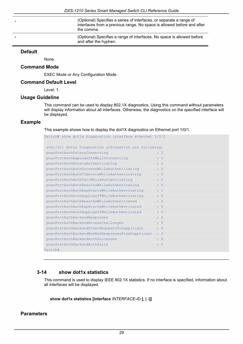
3-13 show dot1x diagnostics This command is used to display IEEE 802.1X diagnostics. If no interface is specified, information about all interfaces will be displayed.
show dot1x diagnostics [interface INTERFACE-ID [, | -]]
Parameters
interface INTERFACE-ID (Optional) Specifies to display the dot1x diagnostics on the specified interface or range of interfaces. If not specified, information about all interfaces will be displayed.
DXS-1210 Series Smart Managed Switch CLI Reference Guide
29
, (Optional) Specifies a series of interfaces, or separate a range of interfaces from a previous range. No space is allowed before and after the comma.
- (Optional) Specifies a range of interfaces. No space is allowed before and after the hyphen.
Default None.
Command Mode EXEC Mode or Any Configuration Mode.
Command Default Level Level: 1.
Usage Guideline This command can be used to display 802.1X diagnostics. Using this command without parameters will display information about all interfaces. Otherwise, the diagnostics on the specified interface will be displayed.
Example This example shows how to display the dot1X diagnostics on Ethernet port 1/0/1. Switch# show dot1x diagnostics interface ethernet 1/0/1
eth1/0/1 dot1x Diagnostics information are following:
pnacPortAuthEntersConnecting : 2
pnacPortAuthEapLogoffsWhileConnecting : 0
pnacPortAuthEntersAuthenticating : 2
pnacPortAuthAuthSuccessWhileAuthenticating : 0
pnacPortAuthAuthTimeoutsWhileAuthenticating : 0
pnacPortAuthAuthFailWhileAuthenticating : 0
pnacPortAuthAuthReauthsWhileAuthenticating : 0
pnacPortAuthAuthEapStartsWhileAuthenticating : 1
pnacPortAuthAuthEapLogoffWhileAuthenticating : 0
pnacPortAuthAuthReauthsWhileAuthenticated : 0
pnacPortAuthAuthEapStartsWhileAuthenticated : 0
pnacPortAuthAuthEapLogoffWhileAuthenticated : 0
pnacPortAuthBackendResponses : 2
pnacPortAuthBackendAccessChallenges : 0
pnacPortAuthBackendOtherRequestsToSupplicant : 0
pnacPortAuthBackendNonNakResponsesFromSupplicant : 2
pnacPortAuthBackendAuthSuccesses : 0
pnacPortAuthBackendAuthFails : 0
Switch#
3-14 show dot1x statistics This command is used to display IEEE 802.1X statistics. If no interface is specified, information about all interfaces will be displayed.
show dot1x statistics [interface INTERFACE-ID [, | -]]
Parameters

DXS-1210 Series Smart Managed Switch CLI Reference Guide
30
interface INTERFACE-ID (Optional) Specifies to display the dot1x diagnostics on the specified interface or range of interfaces. If not specified, information about all interfaces will be displayed.
, (Optional) Specifies a series of interfaces, or separate a range of interfaces from a previous range. No space is allowed before and after the comma.
- (Optional) Specifies a range of interfaces. No space is allowed before and after the hyphen.
Default None.
Command Mode EXEC Mode or Any Configuration Mode.
Command Default Level Level: 1.
Usage Guideline This command can be used to display 802.1X statistics. Using this command without parameters will display information about all interfaces.Otherwise, the statistics on the specified interface will be displayed.
Example This example shows how to display dot1X statistics on Ethernet port 1/0/1. Switch# show dot1x statistics interface eth 1/0/1
eth1/0/1 dot1x statistics information:
EAPOL Frames RX : 1
EAPOL Frames TX : 4
EAPOL-Start Frames RX : 0
EAPOL-Req/Id Frames TX : 6
EAPOL-Logoff Frames RX : 0
EAPOL-Req Frames TX : 0
EAPOL-Resp/Id Frames RX : 0
EAPOL-Resp Frames RX : 0
Invalid EAPOL Frames RX : 0
EAP-Length Error Frames RX : 0
Last EAPOL Frame Version : 0
Last EAPOL Frame Source : 00-10-28-00-19-78
Switch#
3-15 show dot1x session-statistics This command is used to display IEEE 802.1X session statistics. If no interface specified, information about all interfaces will be displayed.
show dot1x session-statistics [interface INTERFACE-ID [, | -]]
Parameters
interface INTERFACE-ID (Optional) Specifies to display the dot1x diagnostics on the specified interface or range of interfaces. If not specified, information about all

DXS-1210 Series Smart Managed Switch CLI Reference Guide
31
interfaces will be displayed.
, (Optional) Specifies a series of interfaces, or separate a range of interfaces from a previous range. No space is allowed before and after the comma.
- (Optional) Specifies a range of interfaces. No space is allowed before and after the hyphen.
Default None.
Command Mode EXEC Mode or Any Configuration Mode.
Command Default Level Level: 1.
Usage Guideline This command can be used to display 802.1X session statistics. Using this command without parameters will display information about all interfaces.Otherwise, the session statistics on the specified interface will be displayed.
Example This example shows how to display dot1X session statistics on Ethernet port 1/0/1. Switch# show dot1x session-statistics interface eth 1/0/1
eth1/0/1 session statistic counters are following:
Octets RX : 0
Octets TX : 0
Frames RX : 0
Frames TX : 0
ID :
AuthenticMethod : Remote Authentication Server
Time : 0
TerminateCause :SupplicantLogoff
User Name :
Switch#
3-16 snmp-server enable traps dot1x This command is used to enable sending SNMP notifications for 802.1X authentication. Use the no form of this command to disable sending SNMP notifications.
snmp-server enable traps dot1x
no snmp-server enable traps dot1x
Parameters None.
Default By default, this option is disabled.
Command Mode Global Configuration Mode.
Command Default Level

DXS-1210 Series Smart Managed Switch CLI Reference Guide
32
Level: 12.
Usage Guideline This command can be used to enable or disable sending SNMP notifications for 802.1X authentication.
Example This example shows how to enable sending trap for 802.1X authentication. Switch# configure terminal
Switch(config)#snmp-server enable traps dot1x
Switch(config)#

DXS-1210 Series Smart Managed Switch CLI Reference Guide
33
4. Access Control List (ACL) Commands 4-1 access-list resequence
This command is used to re-sequence the sequence number of the accesslist entries in an accesslist. Use the no form of this command to revert to the default settings.
access-list resequence {NAME | NUMBER} STARTING-SEQUENCE-NUMBER INCREMENT
no access-list resequence
Parameters
NAME Specifies the name of the accesslist to be configured. It can be a maximum of 32 characters.
NUMBER Specifies the number of the accesslist to be configured.
STARTING-SEQUENCE-NUMBER
Specifies that the access list entries will be re-sequenced using this initial value. The default value is 10. The range of possible sequence numbers is 1 through 65535.
INCREMENT Specifies the number that the sequence numbers step. The default value is 10. For example, if the increment (step) value is 5 and the beginning sequence number is 20, the subsequent sequence numbers are 25, 30, 35, 40, and so on. The range of valid values is from 1 to 32.
Default The default start sequence number is 10.
The default increment is 10.
Command Mode Global Configuration Mode.
Command Default Level Level: 12.
Usage Guideline This feature allows the user to re-sequence the entries of a specified access list with an initial sequence number determined by the STARTING-SEQUENCE-NUMBER parameter and continuing in the increments determined by the INCREMENT parameter. If the highest sequence number exceeds the maximum possible sequence number, then there will be no re-sequencing.
If a rule entry is created without specifying the sequence number, the sequence number will be automatically assigned. If it is the first entry, a start sequence number is assigned. Subsequent rule entries are assigned a sequence number that is increment value greater than the largest sequence number in that access list and the entry is placed at the end of the list.
After the start sequence number or increment change, the sequence number of all previous rules (include the rules that assigned sequence by user) will change according to the new sequence setting.
Example This example shows how to re-sequence the sequence number of an IP access-list, named R&D.

DXS-1210 Series Smart Managed Switch CLI Reference Guide
34
Switch# configure terminal
Switch(config)# show access-list ip R&D
Extended IP access list R&D(ID: 3552)
10 permit tcp any 10.20.0.0 255.255.0.0
20 permit tcp any host 10.100.1.2
30 permit icmp any any
Switch(config)# ip access-list extended R&D
Switch(config-ip-ext-acl)# rule 5 permit tcp any 10.30.0.0 255.255.0.0
Switch(config-ip-ext-acl)# exit
Switch(config)# show access-list ip R&D
Extended IP access list R&D(ID: 3552)5 permit tcp any 10.30.0.0 255.255.0.0
10 permit tcp any 10.20.0.0 255.255.0.0
20 permit tcp any host 10.100.1.2
30 permit icmp any any
Switch(config)# access-list resequence R&D 1 2
Switch(config)# show access-list ip R&D
Extended IP access list R&D(ID: 3552)
1 permit tcp any 10.30.0.0 255.255.0.0
3 permit tcp any 10.20.0.0 255.255.0.0
5 permit tcp any host 10.100.1.2
7 permit icmp any any
Switch(config)#
4-2 acl-hardware-counter This command is used to enable the ACL hardware counter of the specified access-list name for access group functions or access map for the VLAN filter function. Use the no form of this command to disable the ACL hardware counter function.
acl-hardware-counter access-group {ACCESS-LIST-NAME | ACCESS-LIST-NUMBER}
no acl-hardware-counter access-group {ACCESS-LIST-NAME | ACCESS-LIST-NUMBER}
Parameters
access-group ACCESS-LIST-NAME
Specifies the name of the accesslist to be configured.
access-group ACCESS-LIST-NUMBER
Specifies the number of the accesslist to be configured.
Default By default, this option is disabled.
Command Mode Global Configuration Mode.
Command Default Level Level: 12.
Usage Guideline The command with parameter access-group will enable the ACL hardware counter for all ports that have applied the specified access-list name or number. The number of packets, that match each rule, are counted.
The command with parameter vlan-filter will enable the ACL hardware counter for all VLAN(s) that have applied the specified VLAN access-map. The number of packets that permitted by each access map are counted.

DXS-1210 Series Smart Managed Switch CLI Reference Guide
35
Example This example shows how to enable the ACL hardware counter. Switch# configure terminal
Switch(config)#acl-hardware-counter access-group abc
Switch(config)#
4-3 clear acl-hardware-counter This command is used to clear the ACL hardware counter.
clear acl-hardware-counter access-group [ACCESS-LIST-NAME | ACCESS-LIST-NUMBER]
Parameters
access-group ACCESS-LIST-NAME
Specifies the name of the accesslist to be cleared.
access-group ACCESS-LIST-NUMBER
Specifies the number of the accesslist to be configured.
Default None.
Command Mode Privileged EXEC Mode.
Command Default Level Level: 12.
Usage Guideline If no access-list name or number is specified with the parameter access-group, all access-group hardware counters will be cleared. If no access-map name is specified with the parameter vlan-filter, all VLAN filter hardware counters will be cleared.
Example This example shows how to clear the ACL hardware counter. Switch(config)# clear acl-hardware-counter access-group abc
Switch#
4-4 expert access-group This command is used to apply a specific expert ACL to an interface. Use the no form of this command to cancel the application.
expert access-group {NAME | NUMBER} [in]
no expert access-group [NAME | NUMBER] [in]
Parameters
NAME Specifies the name of the expert access-list to be configured. The name can be up to 32 characters.
NUMBER Specifies the number of the expert accesslist to be configured.

DXS-1210 Series Smart Managed Switch CLI Reference Guide
36
in (Optional) Specifies to filter the incoming packets of the interface. If the direction is not specified, in is used.
Default None.
Command Mode Interface Configuration Mode.
Command Default Level Level: 12.
Usage Guideline If expert access group is already configured on the interface, the command applied later will overwrite the previous setting. Only one access-list of the same type can be applied to the same interface; but access-lists of different types can be applied to the same interface.
Example This example shows how to apply an expert ACL to an interface. The purpose is to apply the ACL “exp_acl” on the Ethernet port 1/0/2 to filter the incoming packets. Switch# configure terminal
Switch(config)# interface eth 1/0/2
Switch(config-if)# expert access-group exp_acl in
Switch(config-if)# end
Switch# show access-group interface eth 1/0/2
eth1/0/2:
Inbound expert access-list : exp_acl(ID: 8999)
Switch#
4-5 expert access-list This command is used to create or modify an extended expert ACL. This command will enter into the extended expert access-list configuration mode. Use the no form of this command to remove an extended expert access-list.
expert access-list extended NAME [NUMBER]
no expert access-list extended {NAME | NUMBER}
Parameters
NAME Specifies the name of the extended expert access-list to be configured. The name can be up to 32 characters.
NUMBER Specifies the ID number of expert accesslist. For extended expert accesslists, the value is from 8000 to 9999.
Default None.
Command Mode Global Configuration Mode.
Command Default Level Level: 12.
Usage Guideline

DXS-1210 Series Smart Managed Switch CLI Reference Guide
37
The name must be unique among all access lists. The characters used in the name are case sensitive.If the accesslist number is not specified, the biggest unused number in the range of the expert access list numbers will be assigned automatically.
Example This example shows how to create an extended expert ACL. Switch# configure terminal
Switch(config)# expert access-list extended exp_acl
Switch(config-exp-nacl)# end
Switch# show access-list
Access-List-Name Type
-------------------------------------- ---------------
exp_acl(ID: 8999) expert ext-acl
Total Entries: 1
Switch#
4-6 ip access-group This command is used to specify the IP accesslist to be applied to an interface. Use the no form of this command to remove an IP access list.
ip access-group {NAME | NUMBER} [in]
no ip access-group [NAME | NUMBER] [in]
Parameters
NAME Specifies the name of the IP accesslist to be applied. The maximum length is 32 characters.
NUMBER Specifies the number of the IP accesslist to be applied.
in (Optional) Specifies that the IP access list will be applied to check packets in the ingress direction. If the direction is not specified, in is used.
Default None.
Command Mode Interface Configuration Mode.
Command Default Level Level: 12.
Usage Guideline If an IP access group is already configured on the interface, the command applied later will overwrite the previous setting. Only one access list of the same type can be applied to the same interface; but access-lists of different types can be applied to the same interface.
The association of an access group with an interface will consume the filtering entry resource in the switch controller. If the resources are insufficient to commit the command, then an error message will be displayed. There is a limitation on the number of port operator resources. If applying the command exhausts the available port selectors, then an error message will be displayed.
Example

DXS-1210 Series Smart Managed Switch CLI Reference Guide
38
This example shows how to specify the IP accesslist “Strict-Control” as an IP access group for an Ethernet port 1/0/2. Switch# configure terminal
Switch(config)#interface eth 1/0/2
Switch(config-if)#ip access-group Strict-Control
The remaining applicable IP related access entries are 526
Switch(config-if)#
4-7 ip access-list This command is used to create or modify an IP access list. This command will enter into the IP accesslist configuration mode. Use the no form of this command toremove an IP accesslist.
ip access-list [extended] NAME [NUMBER]
no ip access-list [extended] {NAME | NUMBER}
Parameters
extended (Optional) Specifies that without this option the IP access list is a standard IP access list. When using the extended option, more fields can be chosen for the filter.
NAME Specifies the name of the IP accesslist to be configured. The maximum length is 32 characters. The first character must be a letter.
NUMBER Specifies the ID number of the IP access list. For standard IP access lists, this value is from 1 to 1999. For extended IP access lists, this value is from 2000 to 3999.
Default None.
Command Mode Global Configuration Mode.
Command Default Level Level: 12.
Usage Guideline The name must be unique among all accesslists. The characters used in the name are case sensitive.If the accesslist number is not specified, the biggest unused number in the range of IP access list numbers will be assigned automatically.
Example This example shows how to configure an extended IP accesslist, named “Strict-Control” and an IP access-list, named “pim-srcfilter”. Switch# configure terminal
Switch(config)#ip access-list extended Strict-Control
Swtich(config-ip-ext-acl)# rule permit tcp any 10.20.0.0 255.255.0.0
Swtich(config-ip-ext-acl)# exit
Swtich(config)# ip access-list pim-srcfilter
Switch(config-ip-acl)# rule permit host 172.16.65.193 any
Switch(config-ip-acl)#

DXS-1210 Series Smart Managed Switch CLI Reference Guide
39
4-8 ipv6 access-group This command is used to specify the IPv6 accesslist to be applied to an interface. Use the no form of this command to remove an IPv6 access list.
ipv6 access-group {NAME | NUMBER} [in]
no ipv6 access-group [NAME | NUMBER] [in]
Parameters
NAME Specifies the name of the IPv6 accesslist to be applied.
NUMBER Specifies the number of the IPv6 accesslist to be applied.
in (Optional) Specifies that the IPv6 access list will be applied to check in the ingress direction. If the direction is not specified, in is used.
Default None.
Command Mode Interface Configuration Mode.
Command Default Level Level: 12.
Usage Guideline Only one access list of the same type can be applied to the same interface; but access lists of different types can be applied to the same interface. The association of an access group with an interface will consume the filtering entry resource in the switch controller. If the resource is insufficient to commit the command, then an error message will be displayed.
There is a limitation on the number of port operator resources. If applying the command exhausts the available port selectors, then an error message will be displayed.
Example This example shows how to specify the IPv6 accesslist “ip6-control” as an IP access group for eth3/0/3. Switch# configure terminal
Switch(config)#interface eth 1/0/3
Switch(config-if)# ipv6 access-group ip6-control in
The remaining applicable IPv6 related access entries are 156
Switch(config-if)#
4-9 ipv6 access-list This command is used to create or modify an IPv6 access list. This command will enter into IPv6 access-list configuration mode. Use the no form of this command to remove an IPv6 accesslist.
ipv6 access-list [extended] NAME [NUMBER]
no ipv6 access-list [extended] {NAME | NUMBER}
Parameters
extended (Optional) Specifies that without this option the IPv6 access list is a standard IPv6 access list. When using the extended option, the IPv6

DXS-1210 Series Smart Managed Switch CLI Reference Guide
40
access list is an extended IPv6 access list and more fields can be chosen for the filter.
NAME Specifies the name of the IPv6 accesslist to be configured. The maximum length is 32 characters.
NUMBER Specifies the ID number of the IPv6 access list. For standard IPv6 access lists, this value is from 11000 to 12999. For extended IPv6 access lists, this value is from 13000 to 14999.
Default None.
Command Mode Global Configuration Mode.
Command Default Level Level: 12.
Usage Guideline The name must be unique among all accesslists. The characters used in the name are case sensitive.If the accesslist number is not specified, the biggest unused number in the range of the IPv6 access list numbers will be assigned automatically.
Example This example shows how to configure an IPv6 extended accesslist, named ip6-control. Switch# configure terminal
Switch(config)#ipv6 access-list extended ip6-control
Swtich(config-ipv6-ext-acl)# rule permit tcp any 2002:f03::1/16
Switch(config-ipv6-ext-acl)#
This example shows how to configure an IPv6 standard accesslist, named ip6-std-control. Switch# configure terminal
Switch(config)#ipv6 access-list ip6-std-control
Swtich(config-ipv6-acl)# rule permit any fe80::101:1/54
Switch(config-ipv6-acl)#
4-10 list-remark This command is used to add remarks for the specified ACL. Use the no form of this command todelete the remarks.
list-remark TEXT
no list-remark
Parameters
TEXT Specifies the remark information.The information can be up to 256 characters long.
Default None.
Command Mode Access-list Configuration Mode.

DXS-1210 Series Smart Managed Switch CLI Reference Guide
41
Command Default Level Level: 12.
Usage Guideline This command is available in the MAC, IP, IPv6, and Expert Access-list Configure mode.
Example This example shows how to add a remark to the access-list. Switch# configure terminal
Switch(config)#ip access-list extended R&D
Switch(config-ip-ext-acl)# list-remark “This access-list is used to match any IP packets from the host 10.2.2.1”
Switch(config-ip-ext-acl)# end
Switch# show access-list ip
Extended IP access list R&D(ID: 3999)
10 permit host 10.2.2.1 any
This access-list is used to match any IP packets from the host 10.2.2.1
Switch#
4-11 mac access-group This command is used to specify a MAC accesslist to be applied to an interface. Use the no form of this command to remove the access group control from the interface.
mac access-group {NAME | NUMBER} [in]
no mac access-group [NAME | NUMBER] [in]
Parameters
NAME Specifies the name of the MAC accesslist to be applied.
NUMBER Specifies the number of the MAC accesslist to be applied.
in (Optional) Specifies that the MAC access list will be applied to check in the ingress direction. If direction is not specified, in is used.
Default None.
Command Mode Interface Configuration Mode.
Command Default Level Level: 12.
Usage Guideline If MAC access group is already configured on the interface, the command applied later will overwrite the previous setting. MAC access-groups will only check non-IP packets.
Only one access list of the same type can be applied to the same interface; but access lists of different types can be applied to the same interface.
The association of an access group with an interface will consume the filtering entry resource in the switch controller. If the resource is insufficient to commit the command, then an error message will be displayed.
Example

DXS-1210 Series Smart Managed Switch CLI Reference Guide
42
This example shows how to apply the MAC accesslist daily-profile to Ethernet port 5/0/1. Switch# configure terminal
Switch(config)#interface eth 1/0/1
Switch(config-if)# mac access-group daily-profile in
The remaining applicable MAC access entries are 204
Switch(config-if)#
4-12 mac access-list This command is used to create or modify an MAC access list and this command will enter the MAC access list configuration mode. Use the no form of this command todelete a MAC accesslist.
mac access-list extended NAME [NUMBER]
no mac access-list extended {NAME | NUMBER}
Parameters
NAME Specifies the name of the MAC access-list to be configured. The maximum length is 32 characters.
NUMBER Specifies the ID number of the MAC access list, For extended MAC access lists, this value is from 6000 to 7999.
Default None.
Command Mode Global Configuration Mode.
Command Default Level Level: 12.
Usage Guideline Use this command to enter the MAC access-list configuration mode and use the permit or deny command to specify the entries. The name must be unique among all access lists. The characters of the name are case sensitive.If the accesslist number is not specified, the biggest unused number in the range of the MAC access list numbers will be assigned automatically.
Example This example shows how to enter the MAC accesslist configuration mode for a MAC access list named “daily profile”. Switch# configure terminal
Switch(config)#mac access-list extended daily-profile
Switch(config-mac-ext-acl)#
4-13 permit | deny (expert access-list) This command is used to add a permit or deny entry. Use the no form of this command toremove an entry.
Extended Expert ACL:
rule [SEQUENCE-NUMBER] {permit | deny} PROTOCOL {SRC-IP-ADDR SRC-IP-WILDCARD | host SRC-IP-ADDR | any} {SRC-MAC-ADDR SRC-MAC-WILDCARD | host SRC-MAC-ADDR |

DXS-1210 Series Smart Managed Switch CLI Reference Guide
43
any} {DST-IP-ADDR DST-IP-WILDCARD | host DST-IP-ADDR | any} {DST-MAC-ADDR DST-MAC-WILDCARD | host DST-MAC-ADDR | any} [cos OTER-COS] [vlan OUTER-VLAN] [fragments] [[precedence PRECEDENCE] [tos TOS] | dscp DSCP] [time-range PROFILE-NAME]
rule [SEQUENCE-NUMBER] {permit | deny} tcp {SRC-IP-ADDR SRC-IP-WILDCARD | host SRC-IP-ADDR | any} {SRC-MAC-ADDR SRC-MAC-WILDCARD | host SRC-MAC-ADDR | any} [{eq | lt | gt | neq} PORT | range MIN-PORT MAX-PORT] {DST-IP-ADDR DST-IP-WILDCARD | host DST-IP-ADDR | any} {DST-MAC-ADDR DST-MAC-WILDCARD | host DST-MAC-ADDR | any} [{eq | lt | gt | neq} PORT | range MIN-PORT MAX-PORT] [TCP-FLAG] [cos OUTER-COS] [vlan OUTER-VLAN] [[precedence PRECEDENCE] [tos TOS] | dscp DSCP] [time-range PROFILE-NAME]
rule [SEQUENCE-NUMBER] {permit | deny} udp {SRC-IP-ADDR SRC-IP-WILDCARD | host SRC-IP-ADDR | any} {SRC-MAC-ADDR SRC-MAC-WILDCARD | host SRC-MAC-ADDR | any} [{eq | lt | gt | neq} PORT | range MIN-PORT MAX-PORT] {DST-IP-ADDR DST-IP-WILDCARD | host DST-IP-ADDR | any} {DST-MAC-ADDR DST-MAC-WILDCARD | host DST-MAC-ADDR | any} [{eq | lt | gt | neq} PORT | range MIN-PORT MAX-PORT] [cos OUTER-COS] [vlan OUTER-VLAN] [[precedence PRECEDENCE] [tos TOS] | dscp DSCP] [time-range PROFILE-NAME]
rule [SEQUENCE-NUMBER] {permit | deny} icmp {SRC-IP-ADDR SRC-IP-WILDCARD | host SRC-IP-ADDR | any} {SRC-MAC-ADDR SRC-MAC-WILDCARD | host SRC-MAC-ADDR | any} {DST-IP-ADDR DST-IP-WILDCARD | host DST-IP-ADDR | any} {DST-MAC-ADDR DST-MAC-WILDCARD | host DST-MAC-ADDR | any} [ICMP-TYPE [ICMP-CODE] | ICMP-MESSAGE] [cos OUTER-COS] [vlan OUTER-VLAN] [[precedence PRECEDENCE] [tos TOS] | dscp DSCP] [time-range PROFILE-NAME]
no SEQUENCE-NUMBER
Parameters
SEQUENCE-NUMBER Specifies the sequence number. The range is from 1 to 65535. The lower the number is, the higher the priority of the permit/deny rule.
cos OUTER-COS (Optional) Specifies the outer priority value. This value must be between 0 and 7.
vlan OUTER-VLAN (Optional) Specifies the outer VLAN ID.
any Specifies to use any source MAC address, any destination MAC address, any source IP address, or any destination IP address.
host SRC-MAC-ADDR Specifies a specific source host MAC address.
SRC-MAC-ADDR SRC-MAC-WILDCARD
Specifies a group of source MAC addresses by using a wildcard bitmap. The bit corresponding to the bit value 1 will be ignored. The bit corresponding to bit value 0 will be checked.
host DST-MAC-ADDR Specifies a specific destination host MAC address.
DST-MAC-ADDR DST-MAC-WILDCARD
Specifies a group of destination MAC addresses by using a wildcard bitmap. The bit corresponding to the bit value 1 will be ignored. The bit corresponding to the bit value 0 will be checked.
PROTOCOL (Optional)Specifies the IP protocol ID. Enter the following keywords: eigrp, esp, gre, igmp, ospf, pim, vrrp, pcp, and ipinip.
host SRC-IP-ADDR Specifies a specific source host IP address.
SRC-IP-ADDR SRC-IP-WILDCARD
Specifies a group of source IP addresses by using a wildcard bitmap. The bit corresponding to the bit value 1 will be ignored. The bit corresponding to the bit value 0 will be checked.
host DST-IP-ADDR Specifies a specific destination host IP address.
DST-IP-ADDR DST-IP-WILDCARD
Specifies a group of destination IP addresses by using a wildcard bitmap. The bit corresponding to the bit value 1 will be ignored. The bit corresponding to the bit value 0 will be checked.
precedence PRECEDENCE (Optional) Specifies that packets can be filtered by precedence level, as specified by a number from 0 to 7.

DXS-1210 Series Smart Managed Switch CLI Reference Guide
44
tos TOS (Optional) Specifies that packets can be filtered by type of service level, as specified by a number from 0 to 15.
dscp DSCP (Optional) Specifies the matching DSCP code in IP header. The range is from 0 to 63, or select the following DSCP name: af11 - 001010, af12 -001100, af13 - 001110, af21 - 010010, af22 - 010100, af23 - 010110, af31 - 011010, af32 - 011100, af33 - 011110, af41 - 100010, af42 - 100100, af43 - 100110, cs1 - 001000, cs2 - 010000, cs3 - 011000, cs4 - 100000, cs5 - 101000, cs6 - 110000, cs7 - 111000, default - 000000, ef – 101110.
lt PORT (Optional) Specifies to match if less than the specified port number.
gt PORT (Optional) Specifies to match if greater than the specified port number.
eq PORT (Optional) Specifies to match if equal to the specified port number.
neq PORT (Optional) Specifies to match if not equal to the specified port number.
range MIN-PORT MAX-PORT (Optional) Specifies to match if fall within the range of ports.
TCP-FLAG (Optional) Specifies the TCP flag fields and the specified TCP header bits calledack (acknowledge), fin (finish), psh (push), rst (reset), syn (synchronize), or urg (urgent).
fragments (Optional)Specifies the packet fragment’s filtering.
time-range PROFILE-NAME (Optional) Specifies the name of timeperiod profile associated with the accesslist delineating its activation period.
ICMP-TYPE (Optional) Specifies the ICMP message type. The valid number for the message type is from 0 to 255.
ICMP-CODE (Optional) Specifies the ICMP message code. The valid number for the message code is from 0 to 255.
ICMP-MESSAGE (Optional) Specifies the ICMP message. The following pre-defined parameters are available for selection: beyond-scope, destination-unreachable, echo-reply, echo-request, header, hop-limit, mld-query, mld-reduction, mld-report, nd-na, nd-ns, next-header, no-admin, no-route, packet-too-big, parameter-option, parameter-problem, port-unreachable, reassembly-timeout, redirect, renum-command, renum-result, renum-seq-number, router-advertisement, router-renumbering, router-solicitation, time-exceeded, unreachable.
Default None.
Command Mode Extended Expert Access-list Configuration Mode.
Command Default Level Level: 12.
Usage Guideline If a rule entry is created without a sequence number, a sequence number will be automatically assigned. If it is the first entry, the sequence number 10 is assigned. A subsequent rule entry will be assigned a sequence number that is 10 greater than the largest sequence number in that access list and is placed at the end of the list.
The user can use the command access-list sequence to change the start sequence number and increment number for the specified access list. After the command is applied, the new rule without specified sequence number will be assigned sequence based new sequence setting of the specified access list.
When you manually assign the sequence number, it is better to have a reserved interval for future lower sequence number entries. Otherwise, it will create extra effort to insert an entry with a lower sequence number.

DXS-1210 Series Smart Managed Switch CLI Reference Guide
45
The sequence number must be unique in the domain of an access-list. If you enter a sequence number that is already present, an error message will be shown.
Example This example shows how to use the extended expert ACL. The purpose is to deny all the TCP packets with the source IP address 192.168.4.12 and the source MAC address 00:13:00:49:82:72. Switch# configure terminal
Switch(config)#expert access-list extended exp_acl
Switch(config-exp-nacl)# rule deny tcp host 192.168.4.12 host 0013.0049.8272 any any
Switch(config-exp-nacl)# end
Switch# show access-list expert
Extended EXPERT access list exp_acl(ID: 9998)
10 deny TCP host 192.168.4.12 any host 00:13:00:49:82:72 any
4-14 permit | deny (ip access-list) This command is used to add a permit or a deny entry. Use the no form of this command to remove an entry.
Extended Access List:
rule [SEQUENCE-NUMBER] {permit | deny} tcp {any | host SRC-IP-ADDR | SRC-IP-ADDR SRC-IP-WILDCARD} [{eq | lt | gt | neq} PORT | range MIN-PORT MAX-PORT] {any | host DST-IP-ADDR | DST-IP-ADDR DST-IP-WILDCARD} [{eq | lt | gt | neq} PORT | range MIN-PORT MAX-PORT] [TCP-FLAG] [[precedence PRECEDENCE] [tos TOS] | dscp DSCP] [time-range PROFILE-NAME]
rule [SEQUENCE-NUMBER] {permit | deny} udp {any | host SRC-IP-ADDR | SRC-IP-ADDR SRC-IP-WILDCARD} [{eq | lt | gt | neq} PORT | range MIN-PORT MAX-PORT] {any | host DST-IP-ADDR | DST-IP-ADDR DST-IP-WILDCARD} [{eq | lt | gt | neq} PORT | range MIN-PORT MAX-PORT] [[precedence PRECEDENCE] [tos TOS] | dscp DSCP] [time-range PROFILE-NAME]
rule [SEQUENCE-NUMBER] {permit | deny} icmp {any | host SRC-IP-ADDR | SRC-IP-ADDR SRC-IP-WILDCARD} {any | host DST-IP-ADDR | DST-IP-ADDR DST-IP-WILDCARD} [ICMP-TYPE [ICMP-CODE] | ICMP-MESSAGE] [[precedence PRECEDENCE] [tos TOS] | dscp DSCP] [time-range PROFILE-NAME]
rule [SEQUENCE-NUMBER] {permit | deny} {gre | esp | eigrp | igmp | ipinip | ospf | pcp | pim | vrrp | protocol-id PROTOCOL-ID} {any | host SRC-IP-ADDR | SRC-IP-ADDR SRC-IP-WILDCARD} {any | host DST-IP-ADDR | DST-IP-ADDR DST-IP-WILDCARD} [fragments] [[precedence PRECEDENCE] [tos TOS] | dscp DSCP] [time-range PROFILE-NAME]
rule [SEQUENCE-NUMBER] {permit | deny} {any | host SRC-IP-ADDR | SRC-IP-ADDR SRC-IP-WILDCARD} [any | host DST-IP-ADDR | DST-IP-ADDR DST-IP-WILDCARD] [fragments] [[precedence PRECEDENCE] [tos TOS] | dscp DSCP] [time-range PROFILE-NAME]
Standard IP Access List:
rule [SEQUENCE-NUMBER] {permit | deny} {any | host SRC-IP-ADDR | SRC-IP-ADDR SRC-IP-WILDCARD} [any | host DST-IP-ADDR | DST-IP-ADDR DST-IP-WILDCARD] [time-range PROFILE-NAME] no SEQUENCE-NUMBER
Parameters
SEQUENCE-NUMBER Specifies the sequence number. The range is from 1 to 65535. The lower the number is, the higher the priority of the permit/deny rule.
any Specifies any source IP address or any destination IP address.

DXS-1210 Series Smart Managed Switch CLI Reference Guide
46
host SRC-IP-ADDR Specifies a specific source host IP address.
SRC-IP-ADDR SRC-IP-WILDCARD
Specifies a group of source IP addresses by using a wildcard bitmap. The bit corresponding to the bit value 1 will be ignored. The bit corresponding to the bit value 0 will be checked.
host DST-IP-ADDR Specifies a specific destination host IP address.
DST-IP-ADDR DST-IP-WILDCARD
Specifies a group of destination IP addresses by using a wildcard bitmap. The bit corresponding to the bit value 1 will be ignored. The bit corresponding to the bit value 0 will be checked.
precedence PRECEDENCE (Optional) Specifies that packets can be filtered by precedence level, as specified by a number from 0 to 7.
dscp DSCP (Optional) Specifies the matching DSCP code in IP header. The range is from 0 to 63, or select the following DSCP name: af11 - 001010, af12 -001100, af13 - 001110, af21 - 010010, af22 - 010100, af23 - 010110, af31 - 011010, af32 - 011100, af33 - 011110, af41 - 100010, af42 - 100100, af43 - 100110, cs1 - 001000, cs2 - 010000, cs3 - 011000, cs4 - 100000, cs5 - 101000, cs6 - 110000, cs7 - 111000, default - 000000, ef – 101110.
tos TOS (Optional) Specifies that packets can be filtered by type of service level, as specified by a number from 0 to 15.
lt PORT (Optional) Specifies to match if less than the specified port number.
gt PORT (Optional) Specifies to match if greater than the specified port number.
eq PORT (Optional) Specifies to match if equal to the specified port number.
neq PORT (Optional) Specifies to match if not equal to the specified port number.
range MIN-PORT MAX-PORT (Optional) Specifies to match if fall within the range of ports.
TCP-FLAG (Optional) Specifies the TCP flag fields and the specified TCP header bits calledack (acknowledge), fin (finish), psh (push), rst (reset), syn (synchronize), or urg (urgent).
fragments (Optional)Specifies the packet fragment’s filtering.
time-range PROFILE-NAME (Optional) Specifies the name of the timeperiod profile associated with the accesslist delineating its activation period.
tcp, udp, igmp, ipinip, gre, esp, eigrp, ospf, pcp, pim, vrrp
Specifies Layer 4 protocols.
PROTOCOL-ID (Optional) Specifies the protocol ID. The valid value is from 0 to 255.
ICMP-TYPE (Optional) Specifies the ICMP message type. The valid number for the message type is from 0 to 255.
ICMP-CODE (Optional) Specifies the ICMP message code. The valid number for the message code is from 0 to 255.
ICMP-MESSAGE (Optional) Specifies the ICMP message. The pre-defined parameters are available for selection: administratively-prohibited,alternate-address,conversion-error,host-prohibited,net-prohibited,echo,echo-reply,pointer-indicates-error,host-isolated,host-precedence-violation,host-redirect,host-tos-redirect,host-tos-unreachable,host-unknown,host-unreachable, information-reply,information-request,mask-reply,mask-request,mobile-redirect,net-redirect,net-tos-redirect,net-tos-unreachable, net-unreachable,net-unknown,bad-length,option-missing,packet-fragment,parameter-problem,port-unreachable,precedence-cutoff, protocol-unreachable,reassembly-timeout,redirect-message,router-advertisement,router-solicitation,source-quench,source-route-failed, time-exceeded,timestamp-reply,timestamp-request,traceroute,ttl-expired,unreachable.
Default

DXS-1210 Series Smart Managed Switch CLI Reference Guide
47
None.
Command Mode IP Access-list Configuration Mode.
Command Default Level Level: 12.
Usage Guideline If a rule entry is created without a sequence number, a sequence number will be automatically assigned. If it is the first entry, the sequence number 10 is assigned. A subsequent rule entry will be assigned a sequence number that is 10 greater than the largest sequence number in that access list and is placed at the end of the list.
The user can use the command access-list sequence to change the start sequence number and increment number for the specified access list. After the command is applied, the new rule without specified sequence number will be assigned sequence based new sequence setting of the specified access list.
When you manually assign the sequence number, it is better to have a reserved interval for future lower sequence number entries. Otherwise, it will create extra effort to insert an entry with a lower sequence number.
The sequence number must be unique in the domain of an access-list. If you enter a sequence number that is already present, an error message will be shown.
To create a matching rule for an IP standard access list, only the source IP address or destination IP address fields can be specified.
Example This example shows how to create four entries for an IP extended access list, named Strict-Control. These entries are: permit TCP packets destined to network 10.20.0.0, permit TCP packets destined to host 10.100.1.2, permit all TCP packets go to TCP destination port 80 and permit all ICMP packets. Switch# configure terminal
Switch(config)#ip access-list extended Strict-Control
Switch(config-ip-ext-acl)# rule permit tcp any 10.20.0.0 0.0.255.255
Switch(config-ip-ext-acl)# rule permit tcp any host 10.100.1.2
Switch(config-ip-ext-acl)# rule permit tcp any any eq 80
Switch(config-ip-ext-acl)# rule permit icmp any any
Switch(config-ip-ext-acl)#
This example shows how to create two entries for an IP standard access-list, named “std-ip”.These entries are: permit IP packets destined to network 10.20.0.0, permit IP packets destined to host 10.100.1.2. Switch# configure terminal
Switch(config)#ip access-list std-acl
Switch(config-ip-acl)# rule permit any 10.20.0.0 0.0.255.255
Switch(config-ip- acl)# rule permit any host 10.100.1.2
Switch(config-ip- acl)#
4-15 permit | deny (ipv6 access-list) This command is used to add a permit entry or deny entry to the IPv6 accesslist. Use the no form of this command to remove an entry from the IPv6 accesslist.
Extended IPv6 Access List:
rule [SEQUENCE-NUMBER] {permit | deny} tcp {any | host SRC-IPV6-ADDR | SRC-IPV6-ADDR/PREFIX-LENGTH} [{eq | lt | gt | neq} PORT | range MIN-PORT MAX-PORT] {any | host DST-IPV6-ADDR | DST-IPV6-ADDR/PREFIX-LENGTH} [{eq | lt | gt | neq} PORT | range MIN-

DXS-1210 Series Smart Managed Switch CLI Reference Guide
48
PORT MAX-PORT] [TCP-FLAG] [dscp VALUE] [flow-label FLOW-LABEL] [time-range PROFILE-NAME]
rule [SEQUENCE-NUMBER] {permit | deny} udp {any | host SRC-IPV6-ADDR | SRC-IPV6-ADDR/PREFIX-LENGTH} [{eq | lt | gt | neq} PORT | range MIN-PORT MAX-PORT] {any | host DST-IPV6-ADDR | DST-IPV6-ADDR/PREFIX-LENGTH} [{eq | lt | gt | neq} PORT | range MIN-PORT MAX-PORT] [dscp VALUE] [flow-label FLOW-LABEL] [time-range PROFILE-NAME]
rule [SEQUENCE-NUMBER] {permit | deny} icmp {any | host SRC-IPV6-ADDR | SRC-IPV6-ADDR/PREFIX-LENGTH} {any | host DST-IPV6-ADDR | DST-IPV6-ADDR/PREFIX-LENGTH} [ICMP-TYPE [ICMP-CODE] | ICMP-MESSAGE] [dscp VALUE] [flow-label FLOW-LABEL] [time-range PROFILE-NAME]
rule [SEQUENCE-NUMBER] {permit | deny} {esp | pcp | sctp | protocol-id PROTOCOL-ID} {any | host SRC-IPV6-ADDR | SRC-IPV6-ADDR/PREFIX-LENGTH} {any | host DST-IPV6-ADDR | DST-IPV6-ADDR/PREFIX-LENGTH} [fragments] [dscp VALUE] [flow-label FLOW-LABEL] [time-range PROFILE-NAME]
rule [SEQUENCE-NUMBER] {permit | deny} {any | host SRC-IPV6-ADDR | SRC-IPV6-ADDR/PREFIX-LENGTH} [any | host DST-IPV6-ADDR | DST-IPV6-ADDR/PREFIX-LENGTH] [fragments] [dscp VALUE] [flow-label FLOW-LABEL] [time-range PROFILE-NAME]
Standard IPv6 Access List:
rule [SEQUENCE-NUMBER] {permit | deny} {any | host SRC-IPV6-ADDR | SRC-IPV6-ADDR/PREFIX-LENGTH} [any | host DST-IPV6-ADDR | DST-IPV6-ADDR/PREFIX-LENGTH][time-range PROFILE-NAME]
no SEQUENCE-NUMBER
Parameters
SEQUENCE-NUMBER Specifies the sequence number. The range is from 1 to 65535. The lower the number is, the higher the priority of the permit/deny rule.
any Specifies any source IPv6 address or any destination IPv6 address.
host SRC-IPV6-ADDR Specifies a specific source host IPv6 address.
SRC-IPV6-ADDR/PREFIX-LENGTH
Specifies a source IPv6 network.
host DST-IPV6-ADDR Specifies a specific destination host IPv6 address.
DST-IPV6-ADDR/PREFIX-LENGTH
Specifies a destination IPv6 network.
tcp, udp, icmp, esp, pcp ,sctp Specifies the Layer 4 protocol type.
dscp VALUE (Optional) Specifies the matching traffic class value in IPv6 header. The range is from 0 to 63, or select the following DSCP name: af11 - 001010, af12 -001100, af13 - 001110, af21 - 010010, af22 - 010100, af23 - 010110, af31 - 011010, af32 - 011100, af33 - 011110, af41 - 100010, af42 - 100100, af43 - 100110, cs1 - 001000, cs2 - 010000, cs3 - 011000, cs4 - 100000, cs5 - 101000, cs6 - 110000, cs7 - 111000, default - 000000, ef – 101110.
lt PORT (Optional) Specifies to match if less than the specified port number.
gt PORT (Optional) Specifies to match if greater than the specified port number.
eq PORT (Optional) Specifies to match if equal to the specified port number.
neq PORT (Optional) Specifies to match if not equal to the specified port number.
range MIN-PORT MAX-PORT (Optional) Specifies to match if fall within the range of ports.
PROTOCOL-ID (Optional) Specifies the protocol ID. The valid value is from 0 to 255.
ICMP-TYPE (Optional) Specifies the ICMP message type. The valid number of the message type is from 0 to 255.

DXS-1210 Series Smart Managed Switch CLI Reference Guide
49
ICMP-CODE (Optional)Specifies the ICMP message code. The valid number of the code type is from 0 to 255.
ICMP-MESSAGE (Optional) Specifies the ICMP message. The following pre-defined parameters are available for selection: beyond-scope, destination-unreachable, echo-reply, echo-request, erroneous_header, hop-limit, multicast-listener-query, multicast-listener-done, multicast-listener-report, nd-na, nd-ns, next-header, no-admin, no-route, packet-too-big, parameter-option, parameter-problem, port-unreachable, reassembly-timeout, redirect, renum-command, renum-result, renum-seq-number, router-advertisement, router-renumbering, router-solicitation, time-exceeded, unreachable.
TCP-FLAG (Optional) Specifies the TCP flag fields and the specified TCP header bits calledack (acknowledge), fin (finish), psh (push), rst (reset), syn (synchronize), or urg (urgent).
flow-label FLOW-LABEL (Optional) Specifies the flow label value, within the range of 0 to 1048575.
fragments (Optional)Specifies the packet fragment’s filtering.
time-range PROFILE-NAME (Optional) Specifies the name of time period profile associated with the access list delineating its activation period.
Default None.
Command Mode IPv6 Access-list Configuration Mode.
Command Default Level Level: 12.
Usage Guideline If a rule entry is created without a sequence number, a sequence number will be automatically assigned. If it is the first entry, the sequence number 10 is assigned. A subsequent rule entry will be assigned a sequence number that is 10 greater than the largest sequence number in that access list and is placed at the end of the list.
The user can use the command access-list sequence to change the start sequence number and increment number for the specified access list. After the command is applied, the new rule without specified sequence number will be assigned sequence based new sequence setting of the specified access list.
When you manually assign the sequence number, it is better to have a reserved interval for future lower sequence number entries. Otherwise, it will create extra effort to insert an entry with a lower sequence number.
The sequence number must be unique in the domain of an access-list. If you enter a sequence number that is already present, an error message will be shown.
Example This example shows how to create four entries for an IPv6 extended access list named “ipv6-control”. These entries are: permit TCP packets destined to network ff02::0:2/16, permit TCP packets destined to host ff02::1:2, permit all TCP packets go to port 80 and permit all ICMP packets. Switch# configure terminal
Switch(config)#ipv6 access-list extended ipv6-control
Switch(config-ipv6-ext-acl)# rule permit tcp any ff02::0:2/16
Switch(config-ipv6-ext-acl)# rule permit tcp any host ff02::1:2
Switch(config-ipv6-ext-acl)# rule permit tcp any any eq 80
Switch(config-ipv6-ext-acl)# rule permit icmp any any
Switch(config-ipv6-ext-acl)#

DXS-1210 Series Smart Managed Switch CLI Reference Guide
50
This example shows how to create two entries for an IPv6 standard access-list named “ipv6-std-control”. These entries are: permit IP packets destined to network ff02::0:2/16, and permit IP packets destined to host ff02::1:2. Switch# configure terminal
Switch(config)#ipv6 access-list ipv6-std-control
Switch(config-ipv6-acl)# rule permit any ff02::0:2/16
Switch(config-ipv6-acl)# rule permit any host ff02::1:2
Switch(config-ipv6-acl)#
4-16 permit | deny (mac access-list) This command is used to define the rule for packets that will be permitted or denied. Use the no form of this command to remove an entry
rule [SEQUENCE-NUMBER] {permit | deny} {any | host SRC-MAC-ADDR | SRC-MAC-ADDR SRC-MAC-WILDCARD} {any | host DST-MAC-ADDR | DST-MAC-ADDR DST-MAC-WILDCARD} [ethernet-type TYPE MASK [cos VALUE] [vlan VLAN-ID] [time-range PROFILE-NAME]
no SEQUENCE-NUMBER
Parameters
SEQUENCE-NUMBER Specifies the sequence number. The range is from 1 to 65535. The lower the number is, the higher the priority of the permit/deny rule.
any Specifies any source MAC address or any destination MAC address.
host SRC-MAC-ADDR Specifies a specific source host MAC address.
SRC-MAC-ADDR SRC-MAC-WILDCARD
Specifies a group of source MAC addresses by using a wildcard bitmap. The bit corresponding to the bit value 1 will be ignored. The bit corresponding to the bit value 0 will be checked.
host DST-MAC-ADDR Specifies a specific destination host MAC address.
DST-MAC-ADDR DST-MAC-WILDCARD
Specifies a group of destination MAC addresses by using a wildcard bitmap. The bit corresponding to the bit value 1 will be ignored. The bit corresponding to the bit value 0 will be checked.
ethernet-typeTYPE MASK (Optional) Specifies that the Ethernet type which is a hexadecimal number from 0 to FFFF or the name of an Ethernet type which can be one of the following: aarp, appletalk, decnet-iv, etype-6000, etype-8042, lat, lavc-sca, mop-console, mop-dump, vines-echo, vines-ip, xns-idp., arp.
cos VALUE (Optional) Specifies the priority value of 0 to 7.
vlan VLAN-ID (Optional) Specifies the VLAN-ID.
time-range PROFILE-NAME (Optional) Specifies the name of time period profile associated with the accesslist delineating its activation period
Default None.
Command Mode MAC Access-list Configuration Mode.
Command Default Level Level: 12.
Usage Guideline

DXS-1210 Series Smart Managed Switch CLI Reference Guide
51
If a rule entry is created without a sequence number, a sequence number will be automatically assigned. If it is the first entry, the sequence number 10 is assigned. A subsequent rule entry will be assigned a sequence number that is 10 greater than the largest sequence number in that access list and is placed at the end of the list.
The user can use the command access-list sequence to change the start sequence number and increment number for the specified access list. After the command is applied, the new rule without specified sequence number will be assigned sequence based new sequence setting of the specified access list.
When you manually assign the sequence number, it is better to have a reserved interval for future lower sequence number entries. Otherwise, it will create extra effort to insert an entry with a lower sequence number.
The sequence number must be unique in the domain of an access-list. If you enter a sequence number that is already present, an error message will be displayed.
Multiple entries can be added to the list, and you can use permit for one entry and use deny for the other entry. Different permit and deny commands can match different fields available for setting.
Example This example shows how to configure MAC access entries in the profile daily-profile to allow two sets of source MAC addresses. Switch# configure terminal
Switch(config)#mac access-list extended daily-profile
Switch(config-mac-ext-acl)# rule permit 00:80:33:00:00:00 00:00:00:ff:ff:ff any
Switch(config-mac-ext-acl)# rule permit 00:f4:57:00:00:00 00:00:00:ff:ff:ff any
Switch(config-mac-ext-acl)#
4-17 show access-group This command is used to display access group information for interface(s).
show access-group [interface INTERFACE-ID]
Parameters
interface INTERFACE-ID (Optional) Specifies the interface to be displayed.
Default None.
Command Mode EXEC Mode or Any Configuration Mode.
Command Default Level Level: 1.
Usage Guideline If interface is not specified, all of the interfaces that have access list configured will be displayed.
Example This example shows how to display accesslists that are applied to all of the interfaces.

DXS-1210 Series Smart Managed Switch CLI Reference Guide
52
Switch# show access-group
eth1/0/1:
Inbound mac access-list : simple-mac-acl(ID: 7998)
Inbound ip access-list : simple-ip-acl(ID: 1998)
Switch#
4-18 show access-list This command is used to display the accesslist configuration information.
show access-list [ip [NAME | NUMBER] | mac [NAME | NUMBER] | ipv6 [NAME | NUMBER] | expert [NAME | NUMBER] | arp [NAME]]
Parameters
ip (Optional) Specifies to display a listing of all IP accesslists.
mac (Optional) Specifies to display a listing of all MAC accesslists.
ipv6 (Optional) Specifies to display a listing of all IPv6 accesslists.
expert (Optional) Specifies to display a listing of all expert accesslists.
NAME | NUMBER Specifies to display the contents of the specified accesslist.
arp Specifies to display the ARP access list.
Default None.
Command Mode EXEC Mode or Any Configuration Mode.
Command Default Level Level: 1.
Usage Guideline This command displays access list information. If no option is specified, a listing of all configured access lists is displayed. If the type of access list is specified, detailed information of the access list will be displayed. If the user enables the ACL hardware counter for an access list, the counter will be displayed based on each access list entry.
Example This example shows how to display all access lists.

DXS-1210 Series Smart Managed Switch CLI Reference Guide
53
Switch# show access-list
Access-List-Name Type
-------------------------------------- ---------------
simple-ip-acl(ID: 3998) ip ext-acl
simple-rd-acl(ID: 3999) ip ext-acl
rd-mac-acl(ID: 6998) mac ext-acl
rd-ip-acl(ID: 1998) ip acl
ip6-acl(ID: 12999) ipv6 ext-acl
park-arp-acl arp acl
Total Entries: 6
Switch#
This example shows how to display the IP accesslist called R&D. Switch# show access-list ip R&D
IP access list R&D(ID:3996)
10 permit tcp any 10.20.0.0 0.0.255.255
20 permit tcp any host 10.100.1.2
30 permit icmp any any
Switch#
This example shows how to display the content for the accesslist if its hardware counter is enabled. Switch# show access-list ip simple-ip-acl
IP access list simple-ip-acl(ID:3994)
10 permit tcp any 10.20.0.0 0.0.255.255 (Ing: 12410 packets)
20 permit tcp any host 10.100.1.2 (Ing: 6532 packets)
30 permit icmp any any (Ing: 8758 packets)
Counter enable on following port(s):
Ingress port(s): eth1/0/5-eth1/0/8
Switch#

DXS-1210 Series Smart Managed Switch CLI Reference Guide
54
5. Access Management Commands 5-1 access class
This command is used to specify an access list to restrict the access via a line.Use the no form of this command to remove the specified access list check.
access-class IP-ACL
no access-class IP-ACL
Parameters
IP-ACL Specifies a standard IP access list. The source address field of the permit or deny entry define the valid or invalid host.
Default None.
Command Mode Line Configuration Mode.
Command Default Level Level: 15.
Usage Guideline This command specifies access lists to restrict the access via a line. At most two access lists can be applied to a line. If two access lists are already applied, an attempt to apply a new access list will be rejected until an applied access list is removed by the no form of this command.
Example This example shows how a standard IP access list is created and is specified as the access list to restrict access via Telnet. Only the host 226.1.1.1 is allowed to access the server. Switch# configure terminal
Switch(config)#ip access-list vty-filter
Switch(config-ip-acl)#rule permit 226.1.1.1 0.0.0.0
Switch(config-ip-acl)# exit
Switch(config)# line telnet
Switch(config-line)# access-class vty-filter
Switch(config-line)#
5-2 ip http server This command is used to enable the HTTP server. Use the no form of this command to disable the HTTP server function.
ip http server
no ip http server
Parameters None.
Default

DXS-1210 Series Smart Managed Switch CLI Reference Guide
55
By default, this option is enabled.
Command Mode Global Configuration Mode.
Command Default Level Level: 12.
Usage Guideline This command enables the HTTP server function. The HTTPs access interface is separately controlled by SSL commands.
Example This example shows how to enable the HTTP server. Switch# configure terminal
Switch(config)#ip http server
The SSL function will be set to disable.
Switch(config)#
5-3 ip http secure-server This command is used to enable the HTTPS server. Use the ip http secure-server ssl-service-policycommand to specify which SSL service policy is used for HTTPS. Use the no form of this command todisable the HTTPS server function.
ip http secure-server [ssl-service-policy POLICY-NAME]
no ip http secure-server
Parameters
POLICY-NAME (Optional) Specifies the SSL service policy name. Use this ssl-service-policy keyword only if you have already declared an SSL service policy using the ssl-service-policy command. When no keywordis specified, a built-in local certificate will be used for HTTPS.
Default By default, this option is disabled.
Command Mode Global Configuration Mode.
Command Default Level Level: 15.
Usage Guideline This command enables the HTTPS server function and uses the specified SSL service policy for HTTPS.
Example This example shows how to enable the HTTPS server function and use the service policy called “sp1” for HTTPS. Switch# configure terminal
Switch(config)#ip http secure-server ssl-service-policy sp1
Switch(config)#

DXS-1210 Series Smart Managed Switch CLI Reference Guide
56
5-4 ip http access-class This command is used to specify an access list to restrict the access to the HTTP server. Use the no form of this command to remove the access list check.
ip http access-class IP-ACL
no ip http access-class IP-ACL
Parameters
IP-ACL Specifies a standard IP access list. The source address field of the entry defines the valid or invalid host.
Default None.
Command Mode Global Configuration Mode.
Command Default Level Level: 12.
Usage Guideline This command specifies an access list to restrict the access to the HTTP server. If the specified access list does not exist, the command does not take effect, thus no access list is checked for the user’s access to HTTP.
Example This example shows how a standard IP access list is created and is specified as the access list to access the HTTP server. Only the host 226.1.1.1 is allowed to access the server. Switch# configure terminal
Switch(config)#ip access-list http-filter
Switch(config-ip-acl)# rule permit 226.1.1.1 255.255.255.255
Switch(config-ip-acl)# exit
Switch(config)# ip http access-class http-filter
Switch(config)#
5-5 ip http service-port This command is used to specify the HTTP service port. Use the no form of this command toreturn the service port to 80.
ip http service-port TCP-PORT
no ip http service-port
Parameters
TCP-PORT Specifies the TCP port number. TCP ports are numbered between 1 and 65535. The “well-known” TCP port for the HTTP protocol is 80.
Default By default, this port number is 80.

DXS-1210 Series Smart Managed Switch CLI Reference Guide
57
Command Mode Global Configuration Mode.
Command Default Level Level: 12.
Usage Guideline This command configures the TCP port number for the HTTP server.
Example This example shows how to configure theHTTP TCP port number to 8080. Switch# configure terminal
Switch(config)# ip http service-port 8080
Switch(config)#
5-6 ip http timeout-policy idle This command is used to set idle timeout of a http server connection in seconds. Use the no form of this command toset the idle timeout to default value.
ip http timeout-policy idle INT
no ip http timeout-policy idle
Parameters
INT Specifies the idle timeout value.This value is between 60 and 36000.
Default By default, this value is 180 seconds.
Command Mode Global Configuration Mode.
Command Default Level Level: 12.
Usage Guideline This command is use to configure the idle timeout value of a http server connection in seconds.
Example This example shows how to configure the idle timeout value to 100 seconds . Switch#configure terminal
Switch(config)#ip http timeout-policy idle 100
Switch(config)#
5-7 ip telnet server This command is used to enable a Telnet server. Use the no form of this command to disable the Telnet server function
ip telnet server
no ip telnet server

DXS-1210 Series Smart Managed Switch CLI Reference Guide
58
Parameters None.
Default By default, this option is enabled.
Command Mode Global Configuration Mode.
Command Default Level Level: 12.
Usage Guideline This command enables or disables the Telnet server. The SSH access interface is separately controlled by SSH commands.
Example This example shows how to enable the Telnet server. Switch# configure terminal
Switch(config)# ip telnet server
Switch(config)#
5-8 ip telnet service-port This command is used to specify the service port for Telnet. Use the no form of this command to revert to the default setting.
ip telnet service-port TCP-PORT
no ip telnet service-port
Parameters
TCP-PORT Specifies the TCP port number. TCP ports are numbered between 1 and 65535.The “well-known” TCP port for the TELNET protocol is 23.
Default By default, this value is 23.
Command Mode Global Configuration Mode.
Command Default Level Level: 12.
Usage Guideline This command configures the TCP port number for Telnet access
Example This example shows how to change the Telnet service port number to 3000. Switch# configure terminal
Switch(config)# ip telnet service-port 3000
Switch(config)#

DXS-1210 Series Smart Managed Switch CLI Reference Guide
59
5-9 line This command is used to identify a line type for configuration and enter line configuration mode.
line {console | telnet }
Parameters
console Specifies the local console terminal line.
telnet Specifies the Telnet terminal line
Default None.
Command Mode Global Configuration Mode.
Command Default Level Level: 12.
Usage Guideline The line command is used to enter the Line Configuration Mode.
Example This example shows how to enter the Line Configuration Mode for the console terminal line and configures its access class as”vty-filter”. Switch# configure terminal
Switch(config)#line console
Switch(config-line)# access-class vty-filter
Switch(config-line)#
5-10 service password-encryption This command is used to enable the encryption of the password before stored in the configuration file. Use the no form of this command todisable the encryption.
service password-encryption {7 | 15}
no service password-encryption
Parameters
7 Specifies the password in the encrypted form based on SHA-1.
15 Specifies the password in the encrypted form based on MD5.
Default None.
Command Mode Global Configuration Mode.
Command Default Level Level:15.

DXS-1210 Series Smart Managed Switch CLI Reference Guide
60
Usage Guideline The user account configuration information is stored in the running configuration file and can be applied to the system later. If the service password-encryption command is enabled, the password will be stored in the encrypted form.
When the service password encryption option is disabled and the password is specified in the plain text form, the password will be in plain text form. However, if the password is specified in the encrypted form or if the password has been converted to the encrypted form by the last enable password encryptionoption, the password will still be in the encrypted form. It cannot be reverted back to plain text.
The password affected by this command includes the user account password, enable password, and the authentication password.
Example This example shows how to enable the encryption SHA-1 of the password before stored in the configuration file. Switch# configure terminal
Switch(config)# service password encryption 7
Switch(config)#
5-11 show terminal This command is used to obtain information about the terminal configuration parameter settings for the current terminal line.Use this command in any EXEC mode or any configuration mode.
show terminal
Parameters None.
Default None.
Command Mode EXEC Mode or Any Configuration Mode.
Command Default Level Level: 1.
Usage Guideline Use this command to display information about the terminal configuration parameters for the current terminal line.
Example This example shows how to display information about the terminal configuration parameter settings for the current terminal line.
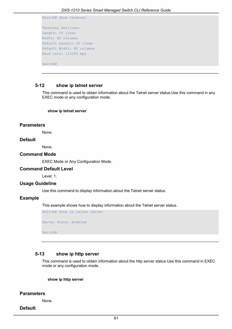
DXS-1210 Series Smart Managed Switch CLI Reference Guide
61
Switch# show terminal
Terminal Settings:
Length: 25 lines
Width: 80 columns
Default Length: 25 lines
Default Width: 80 columns
Baud rate: 115200 bps
Switch#
5-12 show ip telnet server This command is used to obtain information about the Telnet server status.Use this command in any EXEC mode or any configuration mode.
show ip telnet server
Parameters None.
Default None.
Command Mode EXEC Mode or Any Configuration Mode.
Command Default Level Level: 1.
Usage Guideline Use this command to display information about the Telnet server status.
Example This example shows how to display information about the Telnet server status. Switch# show ip telnet server
Server State: Enabled
Switch#
5-13 show ip http server This command is used to obtain information about the http server status.Use this command in EXEC mode or any configuration mode.
show ip http server
Parameters None.
Default

DXS-1210 Series Smart Managed Switch CLI Reference Guide
62
By default, the state is enabled.
Command Mode EXEC Mode or Any Configuration Mode.
Command Default Level Level: 1.
Usage Guideline Use this command to display information about the http server status.
Example This example shows how to display information about the http server status. Switch#show ip http server
ip http server state : enable
Switch#
5-14 show users This command is used to display information about the active lines on the Switch.
show users
Parameters None.
Default None.
Command Mode EXEC Mode or Any Configuration Mode.
Command Default Level Level: 1.
Usage Guideline This command displays information about the active lines on the Switch.
Example This example shows how to display all session information. Switch# show users
ID Type User-Name Privilege Login-Time IP address
-------------------------------------------------------------------------------
0 * console admin 15 4S
Total Entries: 1
Switch#

DXS-1210 Series Smart Managed Switch CLI Reference Guide
63
5-15 terminal length The command is used to configure the number of lines displayed on the screen. The terminal length command will only affect the current session. The terminal length defaultcommand will set the default value but it doesn’t affect the current session. The newly created, saved session terminal length will use the default value. Use the no form of this command to revert to the default setting.
terminal length NUMBER
no terminal length
Parameters
NUMBER Specifies the number of lines to display on the screen. This value must be between 0 and 512.When the terminal length is 0, the display will not stop until it reaches the end of the display.
Default By default, this value is 25.
Command Mode Use the EXEC Mode or Privilege EXEC Mode for the terminal length command.
Command Default Level Level: 1 (for the terminal length command).
Usage Guideline When the terminal length is 0, the display will not stop until it reaches the end of the display.
If the terminal length is specified to a value other than 0, for example 50, then the display will stop after every 50 lines. The terminal length is used to set the number of lines displayed on the current terminal screen. This command also applies to Telnet and SSH sessions. Valid entries are from 0 to 512. The default is 24 lines. A selection of 0's instructs the Switch to scroll continuously (no pausing).
Output from a single command that overflows a single display screen is followed by the --More-- prompt. At the --More-- prompt, press CTRL+C, q, Q, or ESC to interrupt the output and return to the prompt. Press the Spacebar to display an additional screen of output, or press Return to display one more line of output. Setting the screen length to 0 turns off the scrolling feature and causes the entire output to display at once. Unless the default keyword is used, a change to the terminal length value applies only to the current session. When using the no form of this command, the number of lines in the terminal display screen is reset to 24.
Example This example shows how to change the lines to be displayed on a screen to 60. Switch# terminal length 60
Switch#
5-16 session timeout This command is used to configure the line session timeout value. Use the no form of this command to revert to the default setting.
session-timeout MINUTES
no session-timeout
Parameters

DXS-1210 Series Smart Managed Switch CLI Reference Guide
64
MINUTES Specifies the timeout length in minutes. 0 represents never timeout.
Default By default, this value is 3 minutes.
Command Mode Line Configuration Mode.
Command Default Level Level: 12.
Usage Guideline This timer specifies the timeout for auto-logout sessions established by the line that is being configured.
Example This example shows how to configure the console session to never timeout. Switch# configure terminal
Switch(config)# line console
Switch(config-line)# session-timeout 0
Switch(config-line)#
5-17 terminal width The command is used to set the number of character columns on the terminal screen for the current session line. The terminal width command will only affect the current session. The terminal width default command will set the default value, but it doesn’t affect any current sessions.
terminal width NUMBER
no terminal width
Parameters
NUMBER Specifies the number of characters to display on the screen. Valid values are from 40 to 255.
Default By default, this value is 80 characters.
Command Mode Use the EXEC Mode or Privilege EXEC Mode for the terminal width command.
Command Default Level Level: 1 (for the terminal width command).
Usage Guideline By default, the Switch’s system terminal provides a screen display width of 80 characters. The terminal width command changes the terminal width value which applies only to the current session. When changing the value in a session, the value applies only to that session. When the no form of this command is used, the number of lines in the terminal display screen is reset to the default, which is 80 characters.
However, for remote CLI session access such as Telnet, the auto-negotiation terminal width result will take precedence over the default setting if the negotiation is successful. Otherwise, the default settings take effect.

DXS-1210 Series Smart Managed Switch CLI Reference Guide
65
Example This example shows how to adjust the current session terminal width to 120 characters. Switch# show terminal
Terminal Settings:
Length: 25 lines
Width: 80 columns
Default Length: 25 lines
Default Width: 80 columns
Baud rate: 115200 bps
Switch# terminal width 120
Switch# show terminal
Terminal Settings:
Length: 25 lines
Width: 120 columns
Default Length: 25 lines
Default Width: 80 columns
Baud rate: 115200 bps
Switch #
5-18 username This command is used to create a user account. Use the no form of this command to delete the user account.
username NAME [privilege LEVEL] [nopassword | password [0 | 7 | 15] PASSWORD]
no username [NAME]
Parameters
NAME Specifies the user name with a maximum of 32 characters.
privilege LEVEL (Optional) Specifies the privilege level for each user. The privilege level must be between 1 and 15.
nopassword (Optional) Specifies that there will be no password associated with this account.
password (Optional) Specifies the password for the user.
0 (Optional) Specifies the password in clear, plain text. The password length is between 1 and 32 characters and can contain embedded spaces. It is case-sensitive. If the password syntax cannot be specified, the syntax remains plaintext.
7 (Optional) Specifies the encrypted password based on SHA-1. The password length is fixed at 35 bytes. It is case-sensitive. The password is encrypted. If the password syntax is not specified, the syntax is plain text.
15 (Optional) Specifies the encrypted password based on MD5. The password length is fixed at 31 bytes. It is case-sensitive. The password is encrypted. If the password syntax is not specified, the syntax is plain text.
PASSWORD (Optional) Specifies the password string based on the type.

DXS-1210 Series Smart Managed Switch CLI Reference Guide
66
Default By default, the user name is admin, password is admin, and the privilege level is 15.
Command Mode Global Configuration Mode.
Command Default Level Level: 15.
Usage Guideline This command creates user accounts with different access levels. When the user login with Level 1, the user will be in the User EXEC Mode. The user needs to further use the enablecommand to enter the Privileged EXEC Mode.
When the user login with a Level higher than or equal to 2, the user will directly enter the Privileged EXEC Mode. Therefore, the Privileged EXEC Mode can be in Levels 2 to 15.
The user can specify the password in the encrypted form or in the plain-text form. If it is in the plain-text form, but the service passwordencryptionoption is enabled, the password will be converted to the encrypted form.
If the no username command is used without the user name specified, all users are removed.
By default, the user account is empty. When the user account is empty, the user will be directly in the User EXEC Mode at Level 1. The user can further enter the Privileged EXEC Mode using the enable command.
Example This example shows how to create anadministrative username, called admin, and a password, called “mypassword”. Switch# configure terminal
Switch(config)# username admin privilege 15 password 0 mypassword
Switch(config)#
This example shows how to remove the user account with the username admin. Switch# configure terminal
Switch(config)# no username admin
Switch(config)#
5-19 show user-account This command is used to display information about the user accounts created on the Switch.
show user-account
Parameters None.
Default None.
Command Mode EXEC Mode or Any Configuration Mode.
Command Default Level Level: 1.
Usage Guideline

DXS-1210 Series Smart Managed Switch CLI Reference Guide
67
This command displays information about the user accounts created on the Switch.
Example This example shows how to display all user accounts information. Switch# show user-account
User Name Privilege Password Password Type
------------------ --------- -------- -------------
admin 15 ****** Plain Text
Total Entries: 1
Switch#
5-20 show service password-encryption This command is used to display information about the password-encryption.
show service password-encryption
Parameters None.
Default None.
Command Mode EXEC Mode or Any Configuration Mode.
Command Default Level Level: 1.
Usage Guideline This command displays information about the password-encryption.
Example This example shows how to display password-encryption. Switch# show service password-encryption
Password Encryption State: Disabled
Switch#
5-21 show session-timeout This command is used to display information about the session-timeout.
show session-timeout
Parameters None.
Default None.
Command Mode

DXS-1210 Series Smart Managed Switch CLI Reference Guide
68
EXEC Mode or Any Configuration Mode.
Command Default Level Level: 1.
Usage Guideline This command displays information about the session-timeout.
Example This example shows how to display session-timeout. Switch# show session-timeout
Web Session Timeout (second): 36000
Telnet Session Timeout (minute): 30
Console Session Timeout (minute): 30
Switch#
5-22 show ip {http | telnet} service-port This command is used to display information about the http or telnet service port.
show ip {http | telnet} service-port
Parameters
http Specifies the http service port.
telnet Specifies the telnet service port.
Default None.
Command Mode EXEC Mode or Any Configuration Mode.
Command Default Level Level: 1.
Usage Guideline This command displays information about the http or telnet service port.
Example This example shows how to display http service port. Switch# show ip http service-port
IP HTTP server port : 80
Switch#
5-23 ping access-class This command is used to specify an access list to restrict the access to ping switch. Use the no form of the command to remove the access list check.

DXS-1210 Series Smart Managed Switch CLI Reference Guide
69
ping access-class IP-ACL
no ping access-class IP-ACL
Parameters
IP-ACL Specifies a standard IP access list. The source address field of the permit or deny entry define the valid or invalid host.
Default None.
Command Mode Global Configuration Mode.
Command Default Level Level: 12.
Usage Guideline This command is used to specify an access list to restrict the access to ping switch. Use the no form of the command to remove the access list check.
Example This example shows how a standard IP access list is created and is specified as the access list to restrict the access to ping switch.Only the host 226.1.1.1 is allowed to access the server.
Switch# configure terminal
Switch(config)#ip access-list ping-filter
Switch(config-ip-acl)#rule permit 226.1.1.1 255.255.255.0
Switch(config-ip-acl)# exit
Switch(config)# ping access-class ping-filter
Switch(config)#
5-24 ip https access-class This command is used to specify an access list to restrict the access to the HTTPS server. Use the no form of the command to remove the access list check.
ip https access-class IP-ACL
no ip https access-class IP-ACL
Parameters
IP-ACL Specifies a standard IP access list. The source address field of the permit or deny entry define the valid or invalid host.
Default None.
Command Mode Global Configuration Mode.
Command Default Level Level: 12.

DXS-1210 Series Smart Managed Switch CLI Reference Guide
70
Usage Guideline This command is used to specify an access list to restrict the access to the HTTPS server. Use the no form of the command to remove the access list check.
Example This example shows how a standard IP access list is created and is specified as the access list to restrict the access to the HTTPS server.Only the host 226.1.1.1 is allowed to access the server. Switch# configure terminal
Switch(config)#ip access-list https-filter
Switch(config-ip-acl)#rule permit 226.1.1.1 255.255.255.0
Switch(config-ip-acl)# exit
Switch(config)# ip https access-class https-filter
Switch(config)#
5-25 show trusted host This command is used to display trusted host information of telnet,ping, http, https.
show trusted host [telnet | ping | http | https]
Parameters
telnet Specifies the telnet trusted host information.
ping Specifies the ping trusted host information.
http Specifies http telnet trusted host information.
https Specifies https telnet trusted host information.
Default Show all trusted host information.
Command Mode EXEC Mode or Any Configuration Mode.
Command Default Level Level: 1.
Usage Guideline This command is used to display trusted host information for telnet, ping, http, https.
Example This example shows how to display trusted host information of https. Switch# show trusted host https
Type ACL Name
------ --------------------------------
https https-filter
Total Entries: 1
Switch#

DXS-1210 Series Smart Managed Switch CLI Reference Guide
71
6. Asymmetric VLAN Commands 6-1 asymmetric-vlan
This command is used to enable the asymmetric VLAN function. Use the no form of this command to disable the asymmetric VLAN function.
asymmetric-vlan
no asymmetric-vlan
Parameters None.
Default By default, this feature is disabled.
Command Mode Global Configuration Mode.
Command Default Level Level: 12.
Usage Guideline Use this command to enable or disable the asymmetric VLAN function.
Example This example shows how to enable asymmetric VLAN. Switch# configure terminal
Switch(config)# asymmetric-vlan
This example shows how to disable asymmetric VLAN. Switch# configure terminal
Switch(config)# no asymmetric-vlan
6-2 show asymmetric-vlan This command is used to display asymmetric VLAN information
show asymmetric-vlan
Parameters None.
Default None.
Command Mode EXEC Mode or Any Configuration Mode.
Command Default Level Level: 1.

DXS-1210 Series Smart Managed Switch CLI Reference Guide
72
Usage Guideline This command displays asymmetric VLAN information.
Example This example shows how to display asymmetric VLAN information. Switch# show asymmetric-vlan
Asymmetric VLAN State: Disabled
Switch#

DXS-1210 Series Smart Managed Switch CLI Reference Guide
73
7. Authentication, Authorization, and Accounting (AAA) Commands
7-1 aaa authentication dot1x This command is used to configure the default method list used for 802.1X authentication. Use the no form of this command toremove the default method list.
aaa authentication dot1x default METHOD1 [METHOD2...]
no aaa authentication dot1x default
Parameters
METHOD1 [METHOD2...] Specifies the list of methods that the authentication algorithm tries in the given sequence. Enter at least one method or enter up to four methods. The following are keywords that can be used to specify a method. local – Specifies to use the local database for authentication. group radius – Specifies to use the servers defined by the RADIUS server host command. group GROUP-NAME – Specifies to use the server groups defined by the AAA group server. none - Normally, the method is listed as the last method. The user will pass authentication if it is not denied by previous method authentication.
Default No AAA authentication method is configured.
Command Mode Global Configuration Mode.
Command Default Level Level: 15.
Usage Guideline Use this command to configure the default authentication method list for 802.1X authentication. Initially, the default method list is not configured. The authentication of 802.1X requests will be performed based on the local database.
Example This example shows how to set the default methods list for authenticating dot1X users. Switch#configure terminal
Switch(config)# aaa authentication dot1x default group radius
Switch(config)#
7-2 aaa group server radius This command is used to enter the RADIUS group server configuration mode to associate server hosts with the group. Use the no form of this command to remove a RADIUS server group
aaa group server radius GROUP-NAME
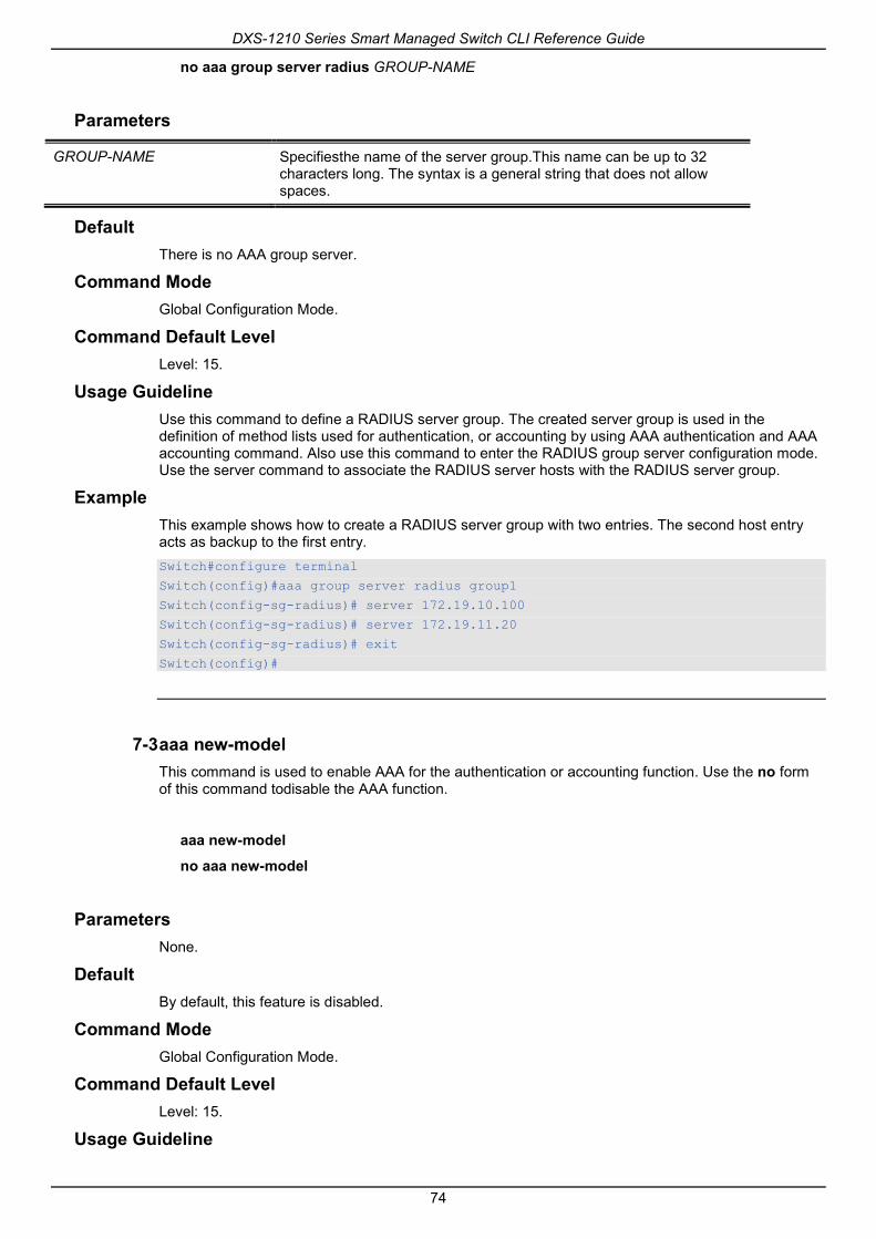
DXS-1210 Series Smart Managed Switch CLI Reference Guide
74
no aaa group server radius GROUP-NAME
Parameters
GROUP-NAME Specifiesthe name of the server group.This name can be up to 32 characters long. The syntax is a general string that does not allow spaces.
Default There is no AAA group server.
Command Mode Global Configuration Mode.
Command Default Level Level: 15.
Usage Guideline Use this command to define a RADIUS server group. The created server group is used in the definition of method lists used for authentication, or accounting by using AAA authentication and AAA accounting command. Also use this command to enter the RADIUS group server configuration mode. Use the server command to associate the RADIUS server hosts with the RADIUS server group.
Example This example shows how to create a RADIUS server group with two entries. The second host entry acts as backup to the first entry. Switch#configure terminal
Switch(config)#aaa group server radius group1
Switch(config-sg-radius)# server 172.19.10.100
Switch(config-sg-radius)# server 172.19.11.20
Switch(config-sg-radius)# exit
Switch(config)#
7-3 aaa new-model This command is used to enable AAA for the authentication or accounting function. Use the no form of this command todisable the AAA function.
aaa new-model
no aaa new-model
Parameters None.
Default By default, this feature is disabled.
Command Mode Global Configuration Mode.
Command Default Level Level: 15.
Usage Guideline

DXS-1210 Series Smart Managed Switch CLI Reference Guide
75
Use this command to enable AAA before the authentication and accounting via the AAA method lists take effect. If AAA is disabled, the login user will be authenticated via the local user account table created by the username command. The enable password will be authenticated via the local table which is defined via the enable password command.
Example This example shows how to enable the AAA function. Switch#configure terminal
Switch(config)# aaa new-model
Switch(config)#
7-4 radius-server deadtime This command is used to specify the default duration of the time to skip the unresponsive server. Use the no form of this command to revert to the default setting.
radius-server deadtime MINUTES
no radius-server deadtime
Parameters
MINUTES Specifies the dead time. The valid range is 0 to 1440 (24 hours). When the setting is 0, the unresponsive server will not be marked as dead.
Default By default, this value is 0.
Command Mode Global Configuration Mode.
Command Default Level Level: 15.
Usage Guideline This command can be used to improve the authentication processing time by setting the dead time to skip the unresponsive server host entries.
When the system performs authentication with the authentication server, it attempts one server at a time. If the attempted server does not respond, the system will attempt the next server. When the system finds a server does not respond, it will mark the server as down, start a dead time timer, and skip them in authentication of the following requests until expiration of the dead time.
Example This example shows how to set the dead time to ten minutes. Switch#configure terminal
Switch(config)# radius-server deadtime 10
Switch(config)#
7-5 radius-server host This command is used to create a RADIUS server host. Use the no form of this command to delete a server host.
radius-server host {IP-ADDRESS | IPV6-ADDRESS} [auth-port PORT]

DXS-1210 Series Smart Managed Switch CLI Reference Guide
76
no radius-server host {IP-ADDRESS | IPV6-ADDRESS}
Parameters
IP-ADDRESS Specifies the IP address of the RADIUS server.
IPV6-ADDRESS Specifies the IPv6 address of the RADIUS server.
auth-port PORT-NUMBER (Optional) Specifies the UDP destination port number for sending authentication packets. The range is 0 to 65535. Set the port number to zero if the server host is not for authentication purposes. The default value is 1812.
Default By default, no server is configured.
Command Mode Global Configuration Mode.
Command Default Level Level: 15.
Usage Guideline Use this command to create RADIUS server hosts before it can be associated with the RADIUS server group using the server command.
Example This example shows how to create two RADIUS server hosts with the different IP address. Switch#configure terminal
Switch(config)#radius-server host 172.19.10.100 auth-port 1500
Switch(config)# radius-server host 172.19.10.101 auth-port 1600
Switch(config)#
7-6 server (RADIUS) This command is used to associate a RADIUS server host with a RADIUS server group. Use the no form of this command to remove a server host from the server group.
server {IP-ADDRESS | IPV6-ADDRESS}
no server {IP-ADDRESS| IPV6-ADDRESS}
Parameters
IP-ADDRESS Specifies the IPv4 address of the authentication server.
IPV6-ADDRESS Specifies the IPv6 address of the authentication server.
Default By default, no server is configured.
Command Mode RADIUS Group Server Configuration Mode.
Command Default Level Level: 15.
Usage Guideline

DXS-1210 Series Smart Managed Switch CLI Reference Guide
77
Use this command to enter the RADIUS group server configuration mode. Use the server command to associate the RADIUS server hosts with the RADIUS server group. The defined server group can be specified as the method list for authentication, or accounting via the AAA authentication and AAA accounting command. Use the radius-server host command to create a server host entry. A host entry is identified by IP Address.
Example This example shows how to create two RADIUS server hosts with the different IP addresses. A server group is then created with the two server hosts. Switch#configure terminal
Switch(config)#radius-server host 172.19.10.100 auth-port 1500 timeout 8 retransmit 3 key ABCDE
Switch(config)# radius-server host 172.19.10.101 auth-port 1600 timeout 3 retransmit 1 key ABCDE
Switch(config)#aaa group server radius group1
Switch(config-sg-radius)# server 172.19.10.100
Switch(config-sg-radius)# server 172.19.10.101
Switch(config-sg-radius)# exit
Switch(config)#
7-7 server (TACACS+) This command is used to associate a TACACS+ server with a server group. Use the no form of this command to remove a server from the server group.
server {IP-ADDRESS | IPV6-ADDRESS}
no server {IP-ADDRESS | IPV6-ADDRESS}
Parameters
IP-ADDRESS Specifies the IPv4 address of the authentication server.
IPV6-ADDRESS Specifies the IPv6 address of the authentication server.
Default By default, no host is in the server group.
Command Mode TACACS+ Group Server Configuration Mode.
Command Default Level Level: 15.
Usage Guideline Use the aaa group server tacacs+ command to enter the TACACS+ group server configuration mode. Use the server command to associate the TACACS+ server hosts with the TACACS+ server group. The defined server group can be specified as the method list for authentication, or accounting via the aaa authentication and aaa accounting command. The configured servers in the group will be attempted in the configured order. Use the tacacs-server host command to create a server host entry. A host entry is identified by the IP Address.
Example This example shows how to create two TACACS+ server hosts. A server group is then created with the two server hosts.

DXS-1210 Series Smart Managed Switch CLI Reference Guide
78
Switch#configure terminal
Switch(config)#tacacs-server host 172.19.10.100 port 1500 timeout 8 key ABCDE
Switch(config)# tacacs-server host 172.19.122.3 port 1600 timeout 3 key ABCDE
Switch(config)#aaa group server tacacs+ group2
Switch(config-sg-tacacs+)# server 172.19.10.100
Switch(config-sg-tacacs+)# server 172.19.122.3
Switch(config-sg-tacacs+)# exit
Switch(config)#
7-8 show aaa This command is used to display the AAA global state.
show aaa
Parameters None.
Default None.
Command Mode Privilege EXEC Mode or Any Configuration Mode.
Command Default Level Level: 1.
Usage Guideline Use this command to display the AAA global state.
Example This example shows how to display the AAA global state. Switch# show aaa
AAA is enabled.
Switch#
7-9 show radius statistics This command is used to display RADIUS statistics for accounting and authentication packets.
show radius statistics
Parameters None.
Default None.
Command Mode

DXS-1210 Series Smart Managed Switch CLI Reference Guide
79
Privilege EXEC Mode or Any Configuration Mode.
Command Default Level Level: 1.
Usage Guideline Use this command to display statistics counters related to servers.
Example This example shows how to display the server related statistics counters. Switch#show radius statistics
RADIUS Server: 172.19.192.80: Auth-Port 1645
Auth.
Round Trip Time: 10
Access Requests: 4
Access Accepts: 0
Access Rejects: 4
Access Challenges: 0
Acct Request: NA
Acct Response: NA
Retransmissions: 0
Malformed Responses: 0
Bad Authenticators: 0
Pending Requests: 0
Timeouts: 0
Unknown Types: 0
Packets Dropped: 0
Display Parameters
Auth. Statistics for authentication packets.
Acct. Statistics for accounting packets.
Round Trip Time The time interval (in hundredths of a second) between the most recent Response and the Request that matched it from this RADIUS server.
Access Requests The number of RADIUS Access-Request packets sent to this server. This does not include retransmissions.
Access Accepts The number of RADIUS Access-Accept packets (valid or invalid) received from this server.
Access Rejects The number of RADIUS Access-Reject packets (valid or invalid) received from this server.
Access Challenges The number of RADIUS Access-Challenge packets (valid or invalid) received from this server.
Acct Request The number of RADIUS Accounting-Request packets sent. This does not include retransmissions.
Acct Response The number of RADIUS packets received on the accounting port from this server.
Retransmissions The number of RADIUS Request packets retransmitted to this RADIUS server. Retransmissions include retries where the Identifier and Acct-Delay have been updated, as well as those in which they remain the same.
Malformed Responses The number of malformed RADIUS Response packets received from this server. Malformed packets include packets with an invalid length. Bad authenticators or Signature attributes or unknown types are not included as malformed responses.

DXS-1210 Series Smart Managed Switch CLI Reference Guide
80
Bad Authenticators The number of RADIUS Response packets containing invalid authenticators or Signature attributes received from this server.
Pending Requests The number of RADIUS Request packets destined for this server that have not yet timed out or received a response. This variable is incremented when a Request is sent and decremented due to receipt of a Response, a timeout or retransmission.
Timeouts The number of timeouts to this server. After a timeout the client may retry to the same server, send to a different server, or give up. A retry to the same server is counted as a retransmit as well as a timeout. A send to a different server is counted as a Request as well as a timeout.
Unknown Types The number of RADIUS packets of unknown type which were received from this server.
Packets Dropped The number of RADIUS packets of which were received from this server and dropped for some other reason.

DXS-1210 Series Smart Managed Switch CLI Reference Guide
81
8. Basic IPv4 Commands 8-1 arp
This command is used to add a static entry in the Address Resolution Protocol (ARP) cache. Use the no form of this command to remove a static entry in the ARP cache.
arp IP-ADDRESS HARDWARE-ADDRESS
no arp IP-ADDRESS HARDWARE-ADDRESS
Parameters
IP-ADDRESS Specifies the network layer IP address.
HARDWARE-ADDRESS Specifies the local data-link Media Access (MAC) address (a 48-bit address).
Default No static entries are installed in the ARP cache.
Command Mode Global Configuration Mode.
Command Default Level Level: 12.
Usage Guideline The ARP table keeps the network layer IP address to local data-link MAC address association. The association is kept so that the addresses will not have to be repeatedly resolved. Use this command to add static ARP entries.
Example This example shows how to add a static ARP entry for a typical Ethernet host. Switch# configure terminal
Switch(config)# arp 10.31.7.19 0800.0900.1834
Switch(config)#
8-2 arp timeout This command is used to set the ARP aging time for the ARP table. Use the no form of this command to revert to the default setting.
arp timeout MINUTES
no arp timeout
Parameters
MINUTES Specifies the dynamic entry that will be aged-out if it has no traffic activity within the timeout period. The valid values are from 0 to 65535.
Default The default value is 20 minutes.

DXS-1210 Series Smart Managed Switch CLI Reference Guide
82
Command Mode Interface Configuration Mode.
Command Default Level Level: 12.
Usage Guideline Used to set the ARP aging time for the ARP table. Use the no form of this command to revert to the default setting.
Example This example shows how to set the ARP timeout to 60 minutes to allow entries to time out more quickly than the default setting. Switch# configure terminal
Switch(config)#interface vlan1
Switch(config-if)# arp timeout 60
Switch(config-if)#
8-3 clear arp-cache This command is used to clear the dynamic ARP entries from the table.
clear arp-cache {all | interface INTERFACE-ID | IP-ADDRESS}
Parameters
all Specifies to clear the dynamic ARP cache entries associated with all interfaces.
INTERFACE-ID Specifies the interface ID.
IP-ADDRESS Specifies the IP address of the specified dynamic ARP cache entry that will be cleared.
Default None.
Command Mode Privileged EXEC Mode.
Command Default Level Level: 12.
Usage Guideline This command is used to delete dynamic entries from the ARP table. The user can select to delete all dynamic entries, specific dynamic entries, or all of the dynamic entries that are associated with a specific interface.
Example This example shows how to remove all dynamic entries from the ARP cache. Switch# clear arp-cache all
Switch#

DXS-1210 Series Smart Managed Switch CLI Reference Guide
83
8-4 ip address This command is used to set a primary or secondary IPv4 address for an interface, or acquire an IP address on an interface from the DHCP. Use the no form of this command to remove the configuration of an IP address or disable DHCP on the interface.
ip address {IP-ADDRESS SUBNET-MASK | dhcp}
no ip address [IP-ADDRESS SUBNET-MASK | dhcp]
Parameters
IP-ADDRESS Specifies the IP address.
SUBNET-MASK Specifies the subnet mask for the associated IP address.
dhcp Specifies to acquire an IP address configuration on an interface from the DHCP protocol.
Default The default IP address for VLAN 1 is 10.90.90.90/8.
Command Mode Interface Configuration Mode.
Command Default Level Level: 12.
Usage Guideline The IPv4 address of an interface can be either manually assigned by the user or dynamically assigned by the DHCP server. For manual assignment, the user can assign multiple networks to a VLAN, each with an IP address. Among these multiple IP addresses, one of them must be the primary IP address and the rest are secondary IP address. The primary address will be used as the source IP address for SNMP trap messages or SYSLOG messages that are sent out from the interface. Use the no ip address command to delete the configured IP address entry.
Example This example shows how to set 10.108.1.27 is the primary address. Switch# configure terminal
Switch(config)#interface vlan100
Switch(config-if)# ip address 10.108.1.27 255.255.255.0
Switch(config-if)# ip address 192.31.7.17 255.255.255.0
Switch(config-if)# ip address 192.31.8.17 255.255.255.0
Switch(config-if)#
8-5 show arp This command is used to display the Address Resolution Protocol (ARP) cache.
show arp [ARP-TYPE] [IP-ADDRESS [MASK]] [INTERFACE-ID] [HARDWARE-ADDRESS]
Parameters
ARP-TYPE (Optional) Specifies the ARP type. dynamic – Specifies to display only dynamic ARP entries. static –Specifies to display only static ARP entries.
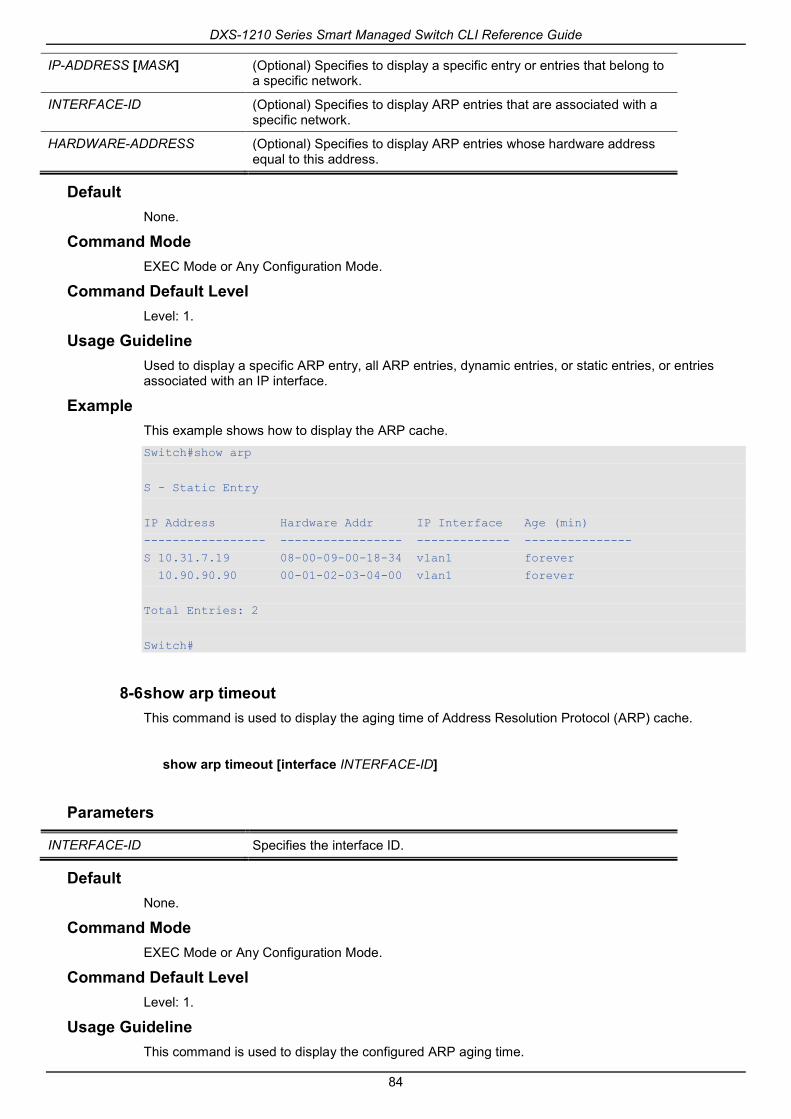
DXS-1210 Series Smart Managed Switch CLI Reference Guide
84
IP-ADDRESS [MASK] (Optional) Specifies to display a specific entry or entries that belong to a specific network.
INTERFACE-ID (Optional) Specifies to display ARP entries that are associated with a specific network.
HARDWARE-ADDRESS (Optional) Specifies to display ARP entries whose hardware address equal to this address.
Default None.
Command Mode EXEC Mode or Any Configuration Mode.
Command Default Level Level: 1.
Usage Guideline Used to display a specific ARP entry, all ARP entries, dynamic entries, or static entries, or entries associated with an IP interface.
Example This example shows how to display the ARP cache. Switch#show arp
S - Static Entry
IP Address Hardware Addr IP Interface Age (min)
----------------- ----------------- ------------- ---------------
S 10.31.7.19 08-00-09-00-18-34 vlan1 forever
10.90.90.90 00-01-02-03-04-00 vlan1 forever
Total Entries: 2
Switch#
8-6 show arp timeout This command is used to display the aging time of Address Resolution Protocol (ARP) cache.
show arp timeout [interface INTERFACE-ID]
Parameters
INTERFACE-ID Specifies the interface ID.
Default None.
Command Mode EXEC Mode or Any Configuration Mode.
Command Default Level Level: 1.
Usage Guideline This command is used to display the configured ARP aging time.

DXS-1210 Series Smart Managed Switch CLI Reference Guide
85
Example This example shows how to display the ARP aging time. Switch#show arp timeout
Interface Timeout (minutes)
------------ -----------------
vlan1 60
------------ -----------------
Total Entries:1
Switch#
8-7 show ip interface This command is used to display the IP interface information.
show ip interface [INTERFACE-ID] [brief]
Parameters
INTERFACE-ID (Optional) Specifies to display information for the specified IP interface.
brief (Optional) Specifies to display a summary of the IP interface information.
Default None.
Command Mode EXEC Mode or Any Configuration Mode.
Command Default Level Level: 1.
Usage Guideline If no parameter is specified, information for all the interfaces will be displayed.
Example This example shows how to display the brief information of the IP interface. Switch#show ip interface brief
Interface IP Address Link Status
---------- --------------- -----------
vlan1 10.90.90.90 up
Total Entries: 1
Switch#
This example shows how to display the IP interface information for VLAN 1.
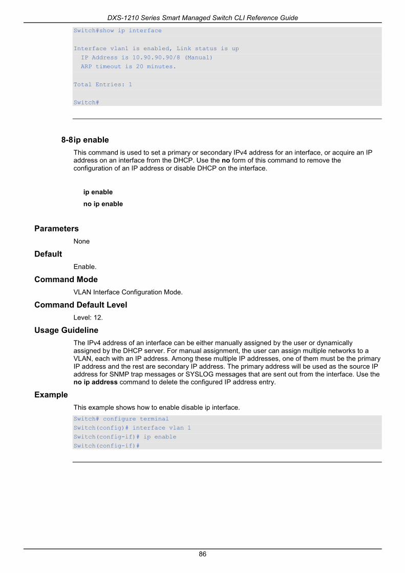
DXS-1210 Series Smart Managed Switch CLI Reference Guide
86
Switch#show ip interface
Interface vlan1 is enabled, Link status is up
IP Address is 10.90.90.90/8 (Manual)
ARP timeout is 20 minutes.
Total Entries: 1
Switch#
8-8 ip enable This command is used to set a primary or secondary IPv4 address for an interface, or acquire an IP address on an interface from the DHCP. Use the no form of this command to remove the configuration of an IP address or disable DHCP on the interface.
ip enable
no ip enable
Parameters None
Default Enable.
Command Mode VLAN Interface Configuration Mode.
Command Default Level Level: 12.
Usage Guideline The IPv4 address of an interface can be either manually assigned by the user or dynamically assigned by the DHCP server. For manual assignment, the user can assign multiple networks to a VLAN, each with an IP address. Among these multiple IP addresses, one of them must be the primary IP address and the rest are secondary IP address. The primary address will be used as the source IP address for SNMP trap messages or SYSLOG messages that are sent out from the interface. Use the no ip address command to delete the configured IP address entry.
Example This example shows how to enable disable ip interface. Switch# configure terminal
Switch(config)# interface vlan 1
Switch(config-if)# ip enable
Switch(config-if)#
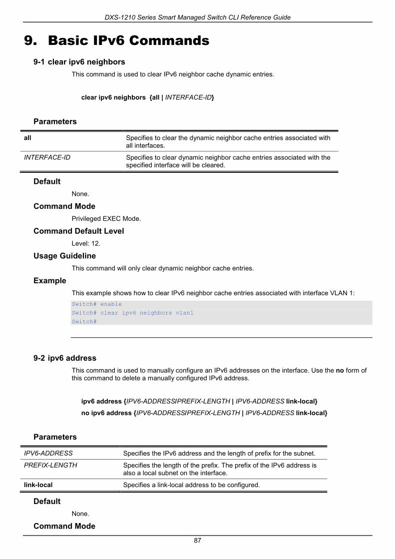
DXS-1210 Series Smart Managed Switch CLI Reference Guide
87
9. Basic IPv6 Commands 9-1 clear ipv6 neighbors
This command is used to clear IPv6 neighbor cache dynamic entries.
clear ipv6 neighbors {all | INTERFACE-ID}
Parameters
all Specifies to clear the dynamic neighbor cache entries associated with all interfaces.
INTERFACE-ID Specifies to clear dynamic neighbor cache entries associated with the specified interface will be cleared.
Default None.
Command Mode Privileged EXEC Mode.
Command Default Level Level: 12.
Usage Guideline This command will only clear dynamic neighbor cache entries.
Example This example shows how to clear IPv6 neighbor cache entries associated with interface VLAN 1: Switch# enable
Switch# clear ipv6 neighbors vlan1
Switch#
9-2 ipv6 address This command is used to manually configure an IPv6 addresses on the interface. Use the no form of this command to delete a manually configured IPv6 address.
ipv6 address {IPV6-ADDRESS/PREFIX-LENGTH | IPV6-ADDRESS link-local}
no ipv6 address {IPV6-ADDRESS/PREFIX-LENGTH | IPV6-ADDRESS link-local}
Parameters
IPV6-ADDRESS Specifies the IPv6 address and the length of prefix for the subnet.
PREFIX-LENGTH Specifies the length of the prefix. The prefix of the IPv6 address is also a local subnet on the interface.
link-local Specifies a link-local address to be configured.
Default None.
Command Mode

DXS-1210 Series Smart Managed Switch CLI Reference Guide
88
Interface Configuration Mode.
Command Default Level Level: 12.
Usage Guideline The IPv6 address can directly be specified by the user or configured based on a general prefix. The general prefix can be acquired by the DHCPv6 client. The general prefix does not need to exist before it can be used in the ipv6 address command. The IPv6 address will not be configured until the general prefix is acquired. The configured IPv6 address will be removed when the general prefix is timeout or removed. The general prefix IPv6 address is formed by the general prefix in the leading part of bits and the sub-bits excluding the general prefix part in the remaining part of bits.
An interface can have multiple IPv6 addresses assigned using a variety of mechanisms, including manual configuration, stateless address configuration, and stateful address configuration. However, within the same prefix, only one IPv6 address can be configured.
When the IPv6 address is configured on an interface, IPv6 processing is enabled for the interface. The prefix of the configured IPv6 address will automatically be advertised as prefix in the RA messages transmitted on the interface.
Example This example shows how to configure an IPv6 address. Switch# configure terminal
Switch(config)#interface vlan 2
Switch(config-if)# ipv6 address 3ffe:22:33:44::55/64
This example shows how to remove an IPv6 address. Switch# configure terminal
Switch(config)# interface vlan 2
Switch(config-if)# no ipv6 address 3ffe:22:3:44::55/64
9-3 ipv6 address dhcp This command is used to configure an interface using DHCPv6 to get an IPv6 address. Use the no form of this command to disable the using of DHCPv6 to get an IPv6 address.
ipv6 address dhcp [rapid-commit]
no ipv6 address dhcp
Parameters
rapid-commit Specifies to proceed with two-message exchange for address delegation. The rapid-commit option will be filled in the Solicit message to request two messages handshake.
Default None.
Command Mode Interface Configuration Mode.
Command Default Level Level: 12.
Usage Guideline

DXS-1210 Series Smart Managed Switch CLI Reference Guide
89
Use this command to configure the interface to use DHCPv6 to get an IPv6 address. When the no ipv6 address dhcp command is used, the previous DHCPv6 obtained IP address will be removed. If the rapid commit keyword is specified for the command, the rapid commit option will be included in the solicit message to request for the two-message exchange for address delegation.
Example This example shows how to configure VLAN 1 to use DHCPv6 to get an IPv6 address. Switch# configure terminal
Switch(config)#interface vlan 1
Switch(config-if)# ipv6 address dhcp
Switch(config-if)#
9-4 ipv6 enable This command is used to enable IPv6 processing on interfaces that have no IPv6 address explicitly configured. Use the no form of this command to disable IPv6 processing on interfaces that have no IPv6 address explicitly configured.
ipv6 enable
no ipv6 enable
Parameters None.
Default By default, this option is disabled.
Command Mode Interface Configuration Mode.
Command Default Level Level: 12.
Usage Guideline When the IPv6 address is explicitly configured on the interface, the IPv6 link-local address is automatically generated and the IPv6 processing is started. When the interface has no IPv6 address explicitly configured, the IPv6 link-local address is not generated and the IPv6 processing is not started. Use the ipv6 enable command to auto-generate the IPv6 link-local address and start the IPv6 processing on the interface.
Example This example shows how to enable IPv6 on interface VLAN 1, which has no IPv6 address explicitly configured. Switch# configure terminal
Switch(config)#interface vlan 1
Switch(config-if)# ipv6 enable
Switch(config-if)#
9-5 ipv6 neighbor This command is used to create a static ipv6 neighbor entry. Use the no form of this command to delete a static IPv6 neighbor entry.

DXS-1210 Series Smart Managed Switch CLI Reference Guide
90
ipv6 neighbor IPV6-ADDRESS INTERFACE-ID MAC-ADDRESS
no ipv6 neighbor IPV6-ADDRESS INTERFACE-ID
Parameters
IPV6-ADDRESS Specifies the IPv6 address of the IPv6 neighbor cache entry.
INTERFACE-ID Specifies the interface for creating the static IPv6 neighbor cache entry.
MAC-ADDRESS Specifies the MAC address of the IPv6 neighbor cache entry.
Default None.
Command Mode Global Configuration Mode.
Command Default Level Level: 12.
Usage Guideline Use this command to create a static IPv6 neighbor cache entry on an interface. The static entry will be either in the REACHABLE state, if the interface is UP, or in the INCOMPLETE state if the interface is down. The reachable detection process will not be applied to the static entries.
The clear ipv6 neighbors command will clear the dynamic neighbor cache entries. Use the no ipv6 neighbor command to delete a static neighbor entry.
Example This example shows how to create a static ipv6 neighbor cache entry. Switch# configure terminal
Switch(config)#ipv6 neighbor fe80::1 vlan1 00-01-80-11-22-99
Switch(config)#
9-6 show ipv6 interface This command is used to display IPv6 interface information.
show ipv6 interface [INTERFACE-ID] [brief]
Parameters
INTERFACE-ID (Optional) Specifies the interface for display.
brief (Optional) Specifies to display brief information.
Default None.
Command Mode EXEC Mode or Any Configuration Mode.
Command Default Level Level: 1.
Usage Guideline

DXS-1210 Series Smart Managed Switch CLI Reference Guide
91
Use this command to display IPv6 interface related configurations.
Example This example shows how to display IPv6 interface information. Switch# show ipv6 interface vlan 2
vlan2 is up, Link status is down
IPv6 is enabled,
link-local address:
FE80::201:1FF:FE02:305
Global unicast address:
200::2/64 (DHCPv6 PD)
RA advertised retransmit interval is 0 milliseconds
Switch#
This example shows how to display brief IPv6 interface information. Switch# show ipv6 interface brief
vlan1 is up, Link status is up
FE80::201:1FF:FE02:304
vlan2 is up, Link status is down
FE80::201:1FF:FE02:305
200::2
vlan3 is up, Link status is down
FE80::201:1FF:FE02:306
Total Entries: 3
Switch#
9-7 show ipv6 neighbors This command is used to display IPv6 neighbor information.
show ipv6 neighbors [INTERFACE-ID] [IPV6-ADDRESS]
Parameters
IPV6-ADDRESS Specifies the IPv6 address to display its IPv6 neighbor cache entry.
INTERFACE-ID Specifies the interface to display IPv6 neighbor cache entry.
Default None.
Command Mode EXEC Mode or Any Configuration Mode.
Command Default Level Level: 1.
Usage Guideline

DXS-1210 Series Smart Managed Switch CLI Reference Guide
92
Use this command to display the IPv6 neighbor cache entry.
Example This example shows how to display the IPv6 neighbor cache entry. Switch# show ipv6 neighbors
IPv6 Address Link-Layer Addr Interface Type State
-------------------------------------- ----------------- --------- ---- -----
FE80::200:11FF:FE22:3344 00-00-11-22-33-44 vlan1 D REACH
Total Entries: 1
Switch#
Display Parameters
Type D – Dynamic learning entry. S – Static neighbor entry.
State INCMP: (Incomplete) Address resolution is being performed on the entry, but the corresponding neighbor advertisement message has not yet been received. REACH: (Reachable) Corresponding neighbor advertisement message was received and the reachable time (in milliseconds) has not elapsed yet. It indicates that the neighbor was functioning properly. STALE: More than the reachable time (in milliseconds) have elapsed since the last confirmation was received. PROBE - Sending the neighbor solicitation message to confirm the reachability.
9-8 ipv6 nd ns-interval This command is used to set advertised NS retransmission interval.
ipv6 nd ns-interval INTERVAL
no ipv6 nd ns-interval
Parameters
INTERVAL Retransmission interval in milliseconds.
Default None.
Command Mode VLAN Interface Configuration Mode.
Command Default Level Level: 12.
Usage Guideline Use this command to set advertised NS retransmission interval.
Example This example shows how to set advertised NS retransmission interval.

DXS-1210 Series Smart Managed Switch CLI Reference Guide
93
Switch# configure terminal
Switch(config)# interface vlan 1
Switch(config-if)# ipv6 nd ns-interval 1200
Switch(config-if)#

DXS-1210 Series Smart Managed Switch CLI Reference Guide
94
10. Cable Diagnostics Commands 10-1 test cable-diagnostics
This command is used to start the cable diagnostics to test the status and length of copper cables.
test cable-diagnostics interface INTERFACE-ID [,|-]
Parameters
interface INTERFACE-ID Specifies the interface ID.
, (Optional) Specifies a series of interfaces, or separate a range of interfaces from a previous range. No space before and after the comma.
- (Optional) Specifies a range of interfaces. No space before and after the hyphen.
Default None.
Command Mode EXEC Mode.
Command Default Level Level: 1.
Usage Guideline The command is available for physical port configuration. Cable Diagnostics can help users to detect whether the copper Ethernet port has connectivity problems. Use the test cable-diagnostics command to start the test. The copper port can be in one of the following status:
• Open: The cable in the error pair does not have a connection at the specified position.
• Short: The cable in the error pair has a short problem at the specified position.
• Open or Short: The cable has an open or short problem, but the PHY has no capability to distinguish between them.
• Crosstalk: The cable in the error pair has a crosstalk problem at the specified position.
• Shutdown: The remote partner is powered off.
• Unknown: The test got an unknown status.
• OK: The pair or cable has no error.
• No cable: The port does not have any cable connection to the remote partner.
Example This example shows how to start the cable diagnostics to test the status and length of copper cables. Switch# test cable-diagnostics interface eth 1/0/1
Switch#
10-2 show cable-diagnostics This command is used to display the test results for the cable diagnostics.
show cable-diagnostics [interface INTERFACE-ID [,|-]]

DXS-1210 Series Smart Managed Switch CLI Reference Guide
95
Parameters
interface INTERFACE-ID (Optional) Specifies the interface’s ID. The acceptable interface will be a physical port.
, (Optional) Specifies a series of interfaces, or separate a range of interfaces from a previous range. No space before and after the comma.
- (Optional) Specifies a range of interfaces. No space before and after the hyphen.
Default None.
Command Mode EXEC Mode.
Command Default Level Level: 1.
Usage Guideline This command is used to display the test results for the cable diagnostics.
Example This example shows how to display the test results for the cable diagnostics. Switch# show cable-diagnostics
Port Type Link Status Test Result Cable Length (M)
------ ---------- ------------- ------------------------------ -----------------
eth1/0/1 1000BASE-T Link Up OK 65
eth1/0/2 1000BASE-T Link Up OK -
eth1/0/3 1000BASE-T Link Down Shutdown 25
eth1/0/4 1000BASE-T Link Down Shutdown -
eth1/0/5 1000BASE-T Link Down Unknown -
eth1/0/6 1000BASE-T Link Down Pair 1 Crosstalk at 30M -
Pair 2 Crosstalk at 30M
Pair 3 OK at 110M
Pair 4 OK at 110M
eth1/0/7 1000BASE-T Link Down NO Cable -
eth1/0/8 1000BASE-T Link Down Pair 1 Open at 16M -
Pair 2 Open at 16M
Pair 3 OK at 50M
Pair 4 OK at 50M
Switch#
10-3 clear cable-diagnostics This command is used to clear the test results for the cable diagnostics.
clear cable-diagnostics {all | interface INTERFACE-ID [,|-]}
Parameters

DXS-1210 Series Smart Managed Switch CLI Reference Guide
96
all Specifies to clear cable diagnostics results for all interfaces.
interface INTERFACE-ID Specifies the interface’s ID. The acceptable interface will be a physical port.
, (Optional) Specifies a series of interfaces, or separate a range of interfaces from a previous range. No space before and after the comma.
- (Optional) Specifies a range of interfaces. No space before and after the hyphen.
Default None.
Command Mode EXEC Mode.
Command Default Level Level: 1.
Usage Guideline This command is used to clear the test results for the cable diagnostics. If the test is running on the interface, an error message will be displayed.
Example This example shows how to clear the test results for the cable diagnostics. Switch# clear cable-diagnostics interface eth 1/0/1
Switch#

DXS-1210 Series Smart Managed Switch CLI Reference Guide
97
11. Debug Commands 11-1 debug show tech-support
This command is used to display the information required by technical support personnel.
debug show tech-support
Parameters None.
Default None.
Command Mode Privileged EXEC Mode or Any Configuration Mode.
Command Default Level Level: 15.
Usage Guideline Use this command to display technical support information. The technical support information is used to collect the Switch’s information needed by the engineers to troubleshoot or analyze a problem.
Example This example shows how to display technical support information of all the modules. Switch# debug show tech-support
#---------------------------------------------------------------------
# DXS-1210-12SC 10GbE Smart Managed Switch
# Technical Support Information
#
# Firmware: V1.15.005
# Copyright(C) 2017 D-Link Corporation. All rights reserved.
#---------------------------------------------------------------------
******************** Basic System Information ********************
Boot Time :0 days, 3 hrs, 21 min, 35 secs
RTC Time :01/01/2017 03:21:34
Boot PROM Version :V1.00.006
Firmware Version :V1.15.005
Hardware Version :A2
MAC Address :00-99-22-88-11-66
Serial Number :QBDGS12102800
SNMP Status :Disabled
Safeguard Engine :Disabled
IGMP Snooping :Disabled
Scheduled Port-shutdown Power Saving :Disabled
Scheduled Hibernation Power Saving :Disabled
Scheduled Dim-LED Power Saving :Disabled
Administrative Dim-LED :Disabled
Switch#

DXS-1210 Series Smart Managed Switch CLI Reference Guide
98
11-2 debug show cpu utilization This command is used to display the total CPU utilization.
debug show cpu utilization
Parameters None.
Default None.
Command Mode Privileged EXEC Mode or Any Configuration Mode.
Command Default Level Level: 15.
Usage Guideline Use this command to display the information about CPU utilization.
Example This example shows how to display the CPU utilization per process information. Switch#debug show cpu utilization
Five seconds - 12 %
Process Name 5Sec
----------------- ------
OS_UTIL 89 %
bcmCNTR.0 2 %
FAN_Pooling 2 %
bcmLINK.0 1 %
GBIC_Pooling 1 %
bcmL2X.0 1 %
HISR1 1 %
Switch#

DXS-1210 Series Smart Managed Switch CLI Reference Guide
99
12. DHCP Client Commands 12-1 ip dhcp client class-id
This command is used to specify the vendor class identifier used as the value of Option 60 for the DHCP discover message. Use the no form of this command to revert the setting to the default.
ip dhcp client class-id {STRING | hex HEX-STRING}
no ip dhcp client class-id
Parameters
STRING Specifiesthe vendor class identifier in the string form. The maximum length of the string is 32.
HEX-STRING Specifies a vendor class identifier in the hexadecimal form. The maximum length of the string is 64.
Default The device type will be used as the class ID.
Command Mode Interface Configuration Mode.
Command Default Level Level: 12.
Usage Guideline Use this command to specify a vendor class identifier (Option 60) to be sent with the DHCP discover message. This specification only applies to the subsequent sending of the DHCP discover messages. The setting only takes effect when the DHCP client is enabled on the interface to acquire the IP address from the DHCP server. The vendor class identifier specifies the type of device that is requesting an IP address.
Example This example shows how to enable the DHCP client, enable the sending of the Vendor Class Identifier, and specifies its value as VOIP-Device for VLAN 100. Switch# configure terminal
Switch(config)#interface vlan 100
Switch(config-if)# ip address dhcp
Switch(config-if)# ip dhcp client class-id VOIP-Device
Switch(config-if)#
12-2 ip dhcp client client-id This command is used to specify the VLAN interface whose hexadecimal MAC address will be used as the client ID sent with the discover message. Use the no form of this command to revert to the default setting
ip dhcp client client-id INTERFACE-ID
no ip dhcp client client-id
Parameters
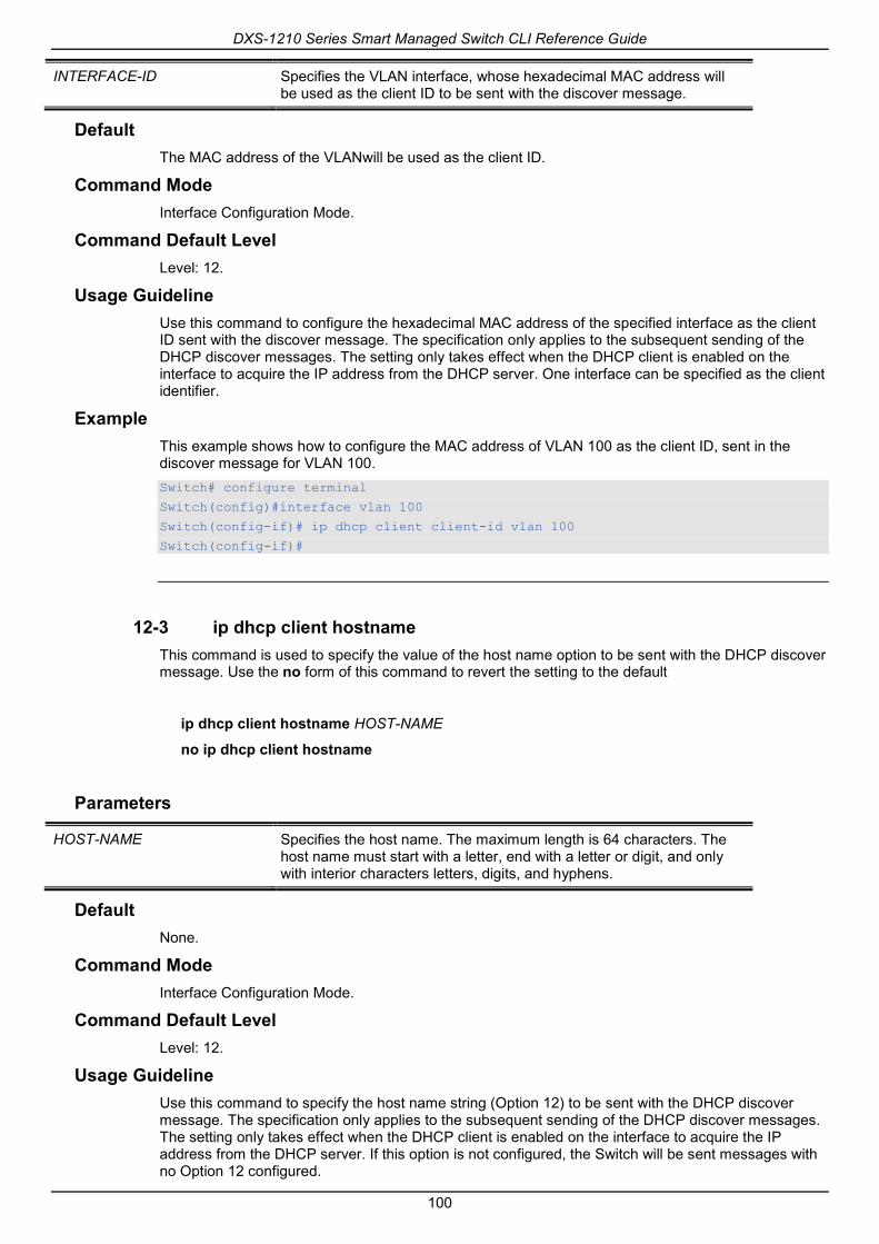
DXS-1210 Series Smart Managed Switch CLI Reference Guide
100
INTERFACE-ID Specifies the VLAN interface, whose hexadecimal MAC address will be used as the client ID to be sent with the discover message.
Default The MAC address of the VLANwill be used as the client ID.
Command Mode Interface Configuration Mode.
Command Default Level Level: 12.
Usage Guideline Use this command to configure the hexadecimal MAC address of the specified interface as the client ID sent with the discover message. The specification only applies to the subsequent sending of the DHCP discover messages. The setting only takes effect when the DHCP client is enabled on the interface to acquire the IP address from the DHCP server. One interface can be specified as the client identifier.
Example This example shows how to configure the MAC address of VLAN 100 as the client ID, sent in the discover message for VLAN 100. Switch# configure terminal
Switch(config)#interface vlan 100
Switch(config-if)# ip dhcp client client-id vlan 100
Switch(config-if)#
12-3 ip dhcp client hostname This command is used to specify the value of the host name option to be sent with the DHCP discover message. Use the no form of this command to revert the setting to the default
ip dhcp client hostname HOST-NAME
no ip dhcp client hostname
Parameters
HOST-NAME Specifies the host name. The maximum length is 64 characters. The host name must start with a letter, end with a letter or digit, and only with interior characters letters, digits, and hyphens.
Default None.
Command Mode Interface Configuration Mode.
Command Default Level Level: 12.
Usage Guideline Use this command to specify the host name string (Option 12) to be sent with the DHCP discover message. The specification only applies to the subsequent sending of the DHCP discover messages. The setting only takes effect when the DHCP client is enabled on the interface to acquire the IP address from the DHCP server. If this option is not configured, the Switch will be sent messages with no Option 12 configured.

DXS-1210 Series Smart Managed Switch CLI Reference Guide
101
Example This example shows how to set the host name option value to Site-A-Switch. Switch# configure terminal
Switch(config)#interface vlan 100
Switch(config-if)# ip dhcp client hostname Site-A-Switch
Switch(config-if)#
12-4 ip dhcp client lease This command is used to specify the preferred lease time for the IP address to request from the DHCP server. Use the no form of this command to disable sending of the lease option.
ip dhcp client lease DAYS [HOURS [MINUTES]]
no ip dhcp client lease
Parameters
DAYS Specifies the day duration of the lease. The range is from 0 to 10000 days.
HOURS (Optional) Specifies the hour duration of the lease. The range is from 0 to 23 hours.
MINUTES (Optional) Specifies the minute duration of the lease. The range is from 0 to 59 minutes.
Default The lease option is not sent.
Command Mode Interface Configuration Mode.
Command Default Level Level: 12.
Usage Guideline The setting only takes effect when the DHCP client is enabled to request the IP address for the interface.
Example This example shows how to get a 5 days release of the IP address. Switch# configure terminal
Switch(config)#interface vlan 100
Switch(config-if)# ip address dhcp
Switch(config-if)# ip dhcp client lease 5
Switch(config-if)#
12-5 dhcp retry times This command is used to specify the DHCP retry times. Use the no form of this command to set DHCP retry times to defualt value.
dhcp retry times <(5-120)>

DXS-1210 Series Smart Managed Switch CLI Reference Guide
102
no dhcp retry times
Parameters
<(5-120)> Specifies the DHCP retry times.
Default 7.
Command Mode Global Configuration Mode..
Command Default Level Level: 12.
Usage Guideline This command is used to specify the DHCP retry times.
Example This example shows how to set DHCP retry times. Switch(config)# configure terminal
Switch(config)# dhcp retry times 10
Switch(config)#
12-6 show dhcp retry times This command is used to display DHCP retry times.
show dhcp retry times
Parameters None
Default None.
Command Mode EXEC Mode
Any Configuration Mode.
Command Default Level Level: 1.
Usage Guideline This command is used to display DHCP retry times.
Example This example shows how to display DHCP retry times.

DXS-1210 Series Smart Managed Switch CLI Reference Guide
103
Switch(config)# show dhcp retry times
DHCP Retry Times: 10
Note: DHCP retry interval: 5 seconds
Switch(config)#
12-7 show ip dhcp interface This command is used to display the DHCP related settings on the interface.
show ip dhcp interface [INTERFACE-ID]
Parameters
INTERFACE-ID Specifies the interface ID.
Default None.
Command Mode EXEC Mode
Any Configuration Mode.
Command Default Level Level: 1.
Usage Guideline This command is used to display the DHCP related settings on the interface.
Example This example shows how to display the DHCP related settings on the interface. Switch(config)# show ip dhcp interface
Interface vlan1
DHCP Client Client-ID:
Class ID String:
Host Name:
Lease:
Total Entries: 1
Switch(config)#

DXS-1210 Series Smart Managed Switch CLI Reference Guide
104
13. DHCPv6 Client Commands 13-1 show ipv6 dhcp
This command is used to display the DHCPv6 related settings on the interface.
show ipv6 dhcp interface [INTERFACE-ID]
Parameters
INTERFACE-ID (Optional) Specifies the VLAN interface to display the DHCPv6 related settings.
Default None.
Command Mode EXEC Mode or Any Configuration Mode.
Command Default Level Level: 1.
Usage Guideline Use this command to display the device’s DHCPv6 DUID or use the show ipv6 dhcp interface command to display DHCPv6 related setting for interfaces. If the interface ID is not specified, all interfaces with the DHCPv6 function will be displayed.
Example This example shows how to display the DHCPv6 setting for interface VLAN 1, when VLAN 1 is DHCPv6 disabled. Switch# show ipv6 dhcp interface vlan1
vlan1 is not in DHCPv6 mode.
Switch#
This example shows how to display the DHCPv6 setting for all VLANs. Only VLANs that are DHCPv6 enabled are displayed. Switch# show ipv6 dhcp interface
vlan1 is in client mode
Rapid-Commit: disabled
Switch#

DXS-1210 Series Smart Managed Switch CLI Reference Guide
105
14. D-Link Discovery Protocol (DDP) Client Commands
14-1 ddp This command is used to enable DDP client function globally or on the specified ports. Use the no form of this command to disable DDP client.
ddp
no ddp
Parameters None.
Default By default, this option is enabled.
Command Mode Global Configuration Mode.
Interface Configuration Mode.
Command Default Level Level: 12.
Usage Guideline Use this command to enable or disable DDP client function globally or per physical port based.
When DDP is disabled on a port, the port will neither process nor generate DDP message. DDP messages received by the port are flooded in VLAN.
Example This example shows how to enable DDP globally. Switch# configure terminal
Switch(config)# ddp
Switch(config)#
This example shows how to enable DDP on port 1/0/1. Switch#configure terminal
Switch(config)#interface ethernet 1/0/1
Switch(config-if)#ddp
Switch(config-if)#
14-2 ddp report-timer This command is used to configure interval between two consecutive DDP report messages. Use the no form of this command to revert to the default setting.
ddp report-timer {30| 60| 90|120 |Never}
no ddp report-timer

DXS-1210 Series Smart Managed Switch CLI Reference Guide
106
Parameters
30 Specifies the report interval to 30 seconds.
60 Specifies the report interval to 60 seconds.
90 Specifies the report interval to 90 seconds.
120 Specifies the report interval to 120 seconds.
Never Specifies to stop sending report message.
Default By default, this option is Never.
Command Mode Global Configuration Mode.
Command Default Level Level: 12.
Usage Guideline Use this command to configure interval between two consecutive DDP report messages.
Example This example shows how to configure interval to 60 seconds. Switch#configure terminal
Switch(config)#ddp report-timer 60
Switch(config)#
14-3 show ddp This command is used to display the switch DDP configurations.
show ddp [ interfaces {INTERFACE-ID [,|-] } ]
Parameters
INTERFACE-ID Specifies to the interface ID.
Default None.
Command Mode EXEC Mode or Any Configuration Mode.
Command Default Level Level: 1.
Usage Guideline Use this command to display the switch DDP configuration information.
Example This example shows how to display DDP global information.

DXS-1210 Series Smart Managed Switch CLI Reference Guide
107
Switch# show ddp
D-Link Discovery Protocol state: Enabled
Report timer: 60 seconds
Switch#
This example shows how to display DDP on port 1/0/1. Switch# show ddp interface ethernet 1/0/1
Interface State
-------------- ----------
eth1/0/1 Enabled
Switch#

DXS-1210 Series Smart Managed Switch CLI Reference Guide
108
15. DoS Prevention Commands 15-1 dos-prevention
This command is used to enable and configure the DoS prevention mechanism. Use the no form of this command to reset DoS prevention to the default setting.
dos-prevention DOS-ATTACK-TYPE
no dos-prevention DOS-ATTACK-TYPE
Parameters
DOS-ATTACK-TYPE Specifies the string that identifies the DoS type to be configured.
Default By default all supported DoS types are disabled.
Command Mode Global Configuration Mode.
Command Default Level Level: 12.
Usage Guideline This command is used to enabled and configure the DoS prevention mechanism for a specific DoS attack type or for all supported types. The DoS prevention mechanisms (matching and taking action) are hardware-based features.
When DoS prevention is enabled, the Switch will log the event if any attack packet was received.
The command no dos-preventionwith the all keyword is used to disable the DoS prevention mechanism for all supported types. All the related settings will be reverted back to the default for the specified attack types.
The following well-known DoS types which can be detected by most switches:
• Blat: This type of attack will send packets with TCP/UDP source port equals to destination port to the target device. It may cause the target device respond to itself.
• Land: A LAND attack involves with IP packets where the source and destination address are set to address of the target device. It may cause the target device reply to itself continuously.
• TCP-NULL-scan: Port scanning by using specific packets, which contain a sequence number of 0 and no flags.
• TCP-SYN-fin: Port scanning by using specific packets, which contain SYN and FIN flags.
• TCP-SYN-SRCport-less-1024: Port scanning by using specific packets, which contain source port 0-1023 and SYN flag.
• TCP-xmas-scan: Port scanning by using specific packets, which contain a sequence number of 0 and the Urgent (URG), Push (PSH), and FIN flags.
• Ping-death: A ping of death is a type of attack on a computer that involves sending a malformed or otherwise malicious ping to a computer. A ping is normally 64 bytes in size; many computers cannot handle a ping larger than the maximum IP packet size, which is 65,535 bytes. Sending a ping of this size can crash the target computer. Traditionally, this bug has been relatively easy to exploit. Generally, sending a 65536 byte ping packet is illegal according to networking protocol, but a packet of such a size can be sent if it is fragmented; when the target computer reassembles the packet, a buffer overflow can occur, which often cause a system crash.

DXS-1210 Series Smart Managed Switch CLI Reference Guide
109
• TCP-tiny-frag: Tiny TCP Fragment attacker uses the IP fragmentation to create extremely small fragments and force the TCP header information into a separate packet fragment to pass through the check function of the router and issue an attack.
• All: All of above types.
Example This example shows how to enable the DoS prevention mechanism for land attack. Switch# configure terminal
Switch(config)# dos-prevention land
Switch(config)#
This example shows how to enable the DoS prevention mechanism on all supported types. Switch# configure terminal
Switch(config)# dos-prevention all
Switch(config)#
This example shows how to disable the DoS prevention mechanism for all supported types. Switch# configure terminal
Switch(config)# no dos-prevention all
Switch(config)#
15-2 show dos-prevention This command is used to display the DoS prevention status and related drop counters.
show dos-prevention [DOS-ATTACK-TYPE]
Parameters
DOS-ATTACK-TYPE (Optional) Specifies the DoS type to be displayed.
Default None.
Command Mode EXEC Mode or Any Configuration Mode.
Command Default Level Level: 1.
Usage Guideline Use this command to display information about DoS prevention.
Example This example shows how to display the configuration information of the DoS prevention.

DXS-1210 Series Smart Managed Switch CLI Reference Guide
110
Switch# show dos-prevention
DoS Prevention Information
DoS Type State
--------------------------------------- --------------
Land Attack Enabled
Blat Attack Enabled
TCP Null Disabled
TCP Xmas Disabled
TCP SYN-FIN Disabled
TCP SYN SrcPort Less 1024 Disabled
Ping of Death Attack Disabled
TCP Tiny Fragment Attack Disabled
Switch#
This example shows how to display the specified type configuration information of theDoS prevention. Switch# show dos-prevention land
DoS Type : Land Attack
State : Enabled
Switch#
15-3 snmp-server enable traps dos-prevention This command is used to enable sending SNMP notifications for DoS attacking. Use the no form of this command to disable sending SNMP notifications.
snmp-server enable traps dos-prevention
no snmp-server enable traps dos-prevention
Parameters None.
Default By default, this option is disabled.
Command Mode Global Configuration Mode.
Command Default Level Level: 12.
Usage Guideline When DoS prevention is enabled, the Switch will log the event if any attacking packet is received every five minutes. You can use this command to enable or disable sending SNMP notifications for such events.
Example This example shows how to enable sending trap for DoS attacking.

DXS-1210 Series Smart Managed Switch CLI Reference Guide
111
Switch#configure terminal
Switch(config)# snmp-server enable traps dos-prevention
Switch(config)#

DXS-1210 Series Smart Managed Switch CLI Reference Guide
112
16. Error Recovery Commands 16-1 errdisable recovery
This command is used to enable the error recovery for causes and to configure the recovery interval. Use the no form of this command to disable the auto-recovery option or to return interval to the default setting for causes.
errdisable recovery cause {all | psecure-violation | storm-control | bpdu-protect | arp-rate | dhcp-rate | loopback-detect} [interval SECONDS]
no errdisable recovery cause {all | psecure-violation | storm-control | bpdu-protect | arp-rate | dhcp-rate | loopback-detect} [interval]
Parameters
All Specifies to enable the auto-recovery option for all causes.
psecure-violation Specifies to enable the auto-recovery option foran error port caused by port security violation.
storm-control Specifies to enable the auto-recovery option foran error port caused by storm control.
bpdu-protect
arp-rate Specifies to enable the auto-recovery option foran error port caused by ARP rate limiting.
dhcp-rate Specifies to enable the auto-recovery option foran error port caused by DHCP rate limiting.
loopback-detect Specifies to enable the auto-recovery option foran error port caused by loop detection.
interval SECONDS Specifies the time, in seconds, to recover the port from the error state caused by the specified module. The valid value is 5 to 86400. The default value is 300 seconds.
Default Auto recovery is disabled for all causes.
Command Mode Global Configuration Mode.
Command Default Level Level: 12.
Usage Guideline A port can be put in an error disabled state by causes such as port security violations, storm control, and so on. When a port enters the error disabled state, the port is shutdown although the setting running the configuration remains in the no shutdown state.
There are two ways to recover an error disabled port. Administrators can use the errdisable recovery cause command to enable the auto-recovery of error ports disabled by each cause. Alternatively, administrators can manually recover the port by entering the shutdown command first and then the no shutdown command for the port.
Example This example shows how to set the recovery timer to 200 seconds for port security violation.

DXS-1210 Series Smart Managed Switch CLI Reference Guide
113
Switch# configure terminal
Switch(config)#errdisable recovery cause psecure-violation interval 200
Switch(config)#
This example shows how to enable the auto-recovery option for port security violations. Switch# configure terminal
Switch(config)#errdisable recovery cause psecurity-violation
Switch(config)#
16-2 show errdisable recovery This command is used to display the error-disable recovery timer related settings.
show errdisable recovery
Parameters None.
Default None.
Command Mode EXEC Mode or Any Configuration Mode.
Command Default Level Level: 1.
Usage Guideline Use this command to verify the settings of the error disable recovery timer.
Example This example shows how to display the settings of the error disable recovery timer. Switch(config)#show errdisable recovery
ErrDisable Cause State Interval
---------------------- ---------- ------------
Port Security disabled 120 seconds
Storm Control disabled 120 seconds
ARP Rate disabled 120 seconds
BPDU Attack Protection disabled 120 seconds
DHCP Rate disabled 120 seconds
Loopback Detect enabled 120 seconds
Interfaces that will be recovered at the next timeout:
Interface vlan ErrDisable Cause Time left
---------- ------ ---------------------- ------------
eth1/0/1 - Loopback Detect 105 seconds
eth1/0/2 - Loopback Detect 105 seconds
Switch#

DXS-1210 Series Smart Managed Switch CLI Reference Guide
114
16-3 snmp-server enable traps errdisable This command is used to enable sending SNMP notifications for error disabled state. Use the no form of this command to disable sending SNMP notifications.
snmp-server enable traps errdisable [asserted] [cleared] [notification-rate TRAP-RATE]
no snmp-server enable traps errdisable [asserted] [cleared] [notification-rate]
Parameters
asserted (Optional) Specifies to control the notifications when entering into the error disabled state.
cleared (Optional) Specifies to control the notifications when exiting from the error disabled state.
notification-rateTRAP-RATE (Optional) Specifies to configure the number of traps per minute. The packets that exceed the rate will be dropped. The range is from 0 to 1000. The default value of 0 indicates that an SNMP trap will be generated for every change of the error disabled state.
Default By default, all notification types are disabled, and there is no limit for the notification rate.
Command Mode Global Configuration Mode.
Command Default Level Level: 12.
Usage Guideline This command with the parameters asserted and cleared enables or disables the notifications for the state change of the error disabled state. If you enter the command with one of the parameters, only the specified notification type is enabled or disabled. The state or value of the other notification type will not be affected.
The snmp-server enable traps errdisable notification-rate and no snmp-server enable traps errdisable notification-ratecommands only affect the setting of notification-rate, but not the state of the sending notifications for the error disabled state.
Example This example shows how to enable sending traps for entering into and exiting from the error disabled state and set the maximum number of traps per second to 3. Switch# configure terminal
Switch(config)#snmp-server enable traps errdisable asserted cleared notification-rate 3
Switch(config)#
16-4 show snmp-server traps error-disable This command is used to display the SNMP notifications for error disabled state.
show snmp-server traps error-disable
Parameters None.

DXS-1210 Series Smart Managed Switch CLI Reference Guide
115
Default None.
Command Mode EXEC Mode or Any Configuration Mode.
Command Default Level Level: 1.
Usage Guideline Use this command to verify the settings of the SNMP notifications for error disabled state.
Example This example shows how to display the settings of the SNMP notifications for error disabled state. Switch# show snmp-server traps error-disable
Error Disable Trap:
Asserted: disabled
Cleared: disabled
Notification Rate: 0

DXS-1210 Series Smart Managed Switch CLI Reference Guide
116
17. Ethernet Ring Protection Switching (ERPS) Commands
For more information, refer to Appendix E - ERPS Information.
17-1 description This command is used to configure the description for Ethernet Ring Protection (ERP) instances.
description DESCRIPTION
no description DESCRIPTION
Parameters None.
Default None.
Command Mode ERP Instance Configuration Mode.
Command Default Level Level: 12.
Usage Guideline This command is used to configure the description for the ERP instances.
Example This example shows how to configure the description for the ERP instances. Switch#configure terminal
Switch(config)# erps instance 1
Switch(config-erp-instance)#description custom-description
Switch(config-erp-instance)#
17-2 ring This command is used to create or modify an ITU-T G.8032 ERP physical ring and enter the ERP configuration mode. Use the no form of this command to delete the specified ring.
ring RING-NAME
no ring RING -NAME
Parameters
RING-NAME
Specifies the name of the ERP ring with the maximum of 32 characters.
Default None.
Command Mode

DXS-1210 Series Smart Managed Switch CLI Reference Guide
117
Global Configuration Mode.
Command Default Level Level: 12.
Usage Guideline This command is used to create, modify or delete an ITU-T G.8032 ERP physical ring and enter the ERP configuration mode.
Example This example shows how to create an ERP ring named “campus”. Switch#configure terminal
Switch(config)# erps instance 1
Switch(config-erps-instance)#ring campus
17-3 ethernet ring g8032 profile This command is used to create or modify a G.8032 profile and enter the ERP profile configuration mode. Use the no form of this command to delete the specified profile.
erps profile PROFILE-NAME
no erps profile PROFILE-NAME
Parameters
PROFILE-NAME Specifies the name of the G.8032 profile with the maximum of 32 characters.
Default None.
Command Mode Global Configuration Mode.
Command Default Level Level: 12.
Usage Guideline This command is used to create, modify or delete a G.8032 profile and enter the ERP profile configuration mode.
Example This example shows how to create a G.8032 profile named “campus”. Switch#configure terminal
Switch(config)# erps profile campus
Switch (config-erps-profile)#
17-4 r-aps channel-vlan This command is used to specify the APS channel VLAN for an ERP instance.Use the no form of this command to delete the configuration.
r-aps channel-vlan VLAN-ID

DXS-1210 Series Smart Managed Switch CLI Reference Guide
118
Parameters
VLAN-ID Specifies the VLAN ID. The valid values are from 1 to 4094.
Default None.
Command Mode ERP Instance Configuration Mode.
Command Default Level Level: 12.
Usage Guideline This command is used to assign the APS channel VLAN for an ERP instance. The APS channel VLAN needs to be assigned before an ERP instance can be set to the operation state.
The specified APS channel VLAN does not need to exist to configure the command. But it needs to exist before the instance can be set to the operation state.
If the APS channel VLAN is removed when the ERP instance is in operation, the ERP instance will enter the operational disabled state.
Each ERP instances should have distinct APS channel VLAN.
Example This example shows how toconfigure the APS channel VLAN “2” for the ERP instance “1”. Switch(config)# erps instance 1
Switch(config-erp-instance)#r-aps channel-vlan 2
Switch(config-erp-instance)#
17-5 inclusion-list vlan-ids This command is used to configure VLAN IDs protected by the ERP mechanism.Use the no form of this command to delete the VLAN IDs.
inclusion-list vlan-ids VLAN-ID [, | -]
no inclusion-list vlan-ids VLAN-ID [, | -]
Parameters
VLAN-ID Specified the VLAN IDs protected by the ERP mechanism. The range is 1 to 4094.
, (Optional) Specifies a series of VLANs, or separate a range of VLANs from a previous range. No spacesare required before and after the comma.
- (Optional) Specifies a range of VLANs. No spacesare required before and after the hyphen.
Default None.
Command Mode ERP Instance Configuration Mode.
Command Default Level

DXS-1210 Series Smart Managed Switch CLI Reference Guide
119
Level: 12.
Usage Guideline This command is used to add or delete VLAN IDs protected by the ERP mechanism.
Example This example shows how toconfigure service protected VLAN as 100-200 for ERP instance 1. Switch#configure terminal
Switch(config)# erps instance 1
Switch(config-erp-instance)#inclusion-list vlan-ids 100-200
Switch(config-erp-instance)#
17-6 instance This command is used to create an ERP instance and enter ERP instance configuration mode.Use the no form of this command to remove an ERP instance.
erps instance INSTANCE-ID
no erps instance INSTANCE-ID
Parameters
INSTANCE-ID Specifies an ERP instance number. The valid values are from 1 to 32.
Default None.
Command Mode ERP Configuration Mode.
Command Default Level Level: 12.
Usage Guideline This command is used to create or remove an ERP instance and enter ERP instance configuration mode.
Example This example shows how to create the ERP instance “1” in the physical ring named “ring2”. Switch#configure terminal
Switch(config)# erps instance 1
Switch(config-erp-instance)#
17-7 level This command is used to configure ring MEL value of an ERP instance.Use the no form of this command to revert to the default setting.
level MEL-VALUE
no level
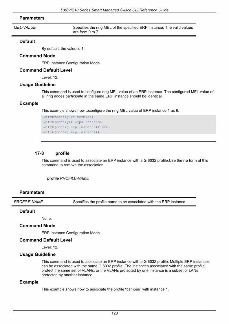
DXS-1210 Series Smart Managed Switch CLI Reference Guide
120
Parameters
MEL-VALUE Specifies the ring MEL of the specified ERP instance. The valid values are from 0 to 7.
Default By default, the value is 1.
Command Mode ERP Instance Configuration Mode.
Command Default Level Level: 12.
Usage Guideline This command is used to configure ring MEL value of an ERP instance. The configured MEL value of all ring nodes participate in the same ERP instance should be identical.
Example This example shows how toconfigure the ring MEL value of ERP instance 1 as 6. Switch#configure terminal
Switch(config)# erps instance 1
Switch(config-erp-instance)#level 6
Switch(config-erp-instance)#
17-8 profile This command is used to associate an ERP instance with a G.8032 profile.Use the no form of this command to remove the association
profile PROFILE-NAME
Parameters
PROFILE-NAME Specifies the profile name to be associated with the ERP instance.
Default None.
Command Mode ERP Instance Configuration Mode.
Command Default Level Level: 12.
Usage Guideline This command is used to associate an ERP instance with a G.8032 profile. Multiple ERP instances can be associated with the same G.8032 profile. The instances associated with the same profile protect the same set of VLANs, or the VLANs protected by one instance is a subset of LANs protected by another instance.
Example This example shows how to associate the profile “campus” with instance 1.

DXS-1210 Series Smart Managed Switch CLI Reference Guide
121
Switch#configure terminal
Switch(config)# erps instance 1
Switch(config-erp-instance)#profile campus
Switch(config-erp-instance)#
17-9 port0 This command is used to specify the first ring port of a physical ring. Use the no form of this command to remove the settings.
port0 interface INTERFACE-ID
Parameters
INTERFACE-ID Specifies the interface ID of the first ring port. The interface(s) can be a physical interface or a port-channel.
Default None.
Command Mode ERP Configuration Mode.
Command Default Level Level: 12.
Usage Guideline This command is used to specify or remove the first ring port of a physical ring.
Example This example shows how to configure the interface “eth1/0/1” as the first ring port of the G.8032 ring “ring1”. Switch#configure terminal
Switch(config)# erps instance 1
Switch(config-erps-instance)# port0 interface eth 1/0/1
Switch(config-erps-instance)#
17-10 port1 This command is used to specify the second ring port of a physical ring. Use the no form of this command to remove the settings.
port1 {interface INTERFACE_ID }
Parameters
INTERFACE_ID Specifies the interface ID of the second ring port. The interface(s) can be a physical interface or a port-channel.
Default None.
Command Mode

DXS-1210 Series Smart Managed Switch CLI Reference Guide
122
ERP Configuration Mode.
Command Default Level Level: 12.
Usage Guideline This command is used to specify or remove the first ring port of a physical ring.
Example This example shows how to configure the inter-connect node as a local end node of the G.8032 ring “ring2”. Switch#configure terminal
Switch(config)# erps instance 1
Switch(config-erps-instance)# port1 interface eth 1/0/1
Switch(config-erps-instance)#
17-11 revertive This command is used to revert back to the working transport entity, for example, when the RPL was blocked. Use the no form of this command to continue using the RPL, if it has not failed and if the ‘switch link defect’ condition was cleared.
revertive
no revertive
Parameters None.
Default By default, this option is revertive.
Command Mode G.8032 Profile Configuration Mode.
Command Default Level Level: 12.
Usage Guideline When a defect was cleared, the traffic channel will revert after the WTR timer has expired, which is used to avoid toggling protection states caused by intermitted defects.
In the non-revertive operation, the traffic channel continues to use the RPL if it did not fail after a ‘switch link defect’ condition was cleared. Since in Ethernet ring protection the working transport entity resources may be more optimized and in some cases it is more desirable to revert to this working transport entity once all ring links are available. This is performed at the expense of an additional traffic interruption. In some cases there may be no advantage to revert back to the working transport entity immediately and in some cases a second traffic interruption is even avoided by not reverting protect switching.
Example This example shows how to configure rings in the profile “campus” to operate in non-revertive mode. Switch#configure terminal
Switch(config)# erps profile campus
Switch (config-erps-profile)# no revertive
Switch (config-erps-profile)#

DXS-1210 Series Smart Managed Switch CLI Reference Guide
123
17-12 rpl This command is used to configure the node as the RPL owner, or assign the port as the RPL port.Use the no form of this command to remove the settings.
rpl {port0 | port1} [owner]
no rpl
Parameters
port0 Specified port0 as the RPL port.
port1 Specified port1 as the RPL port.
owner (Optional) Specifies the ring node as the RPL owner node.
Default None.
Command Mode ERP Instance Configuration Mode.
Command Default Level Level: 12.
Usage Guideline This command is used to configure the node as the RPL owner or RPL neighbor, or assign the port as the RPL port.
Example This example shows how to configure port0 as the RPL port of the ERP instance “1”. Switch#configure terminal
Switch(config)# erps instance 1
Switch(config-erp-instance)#rpl port0
Switch(config-erp-instance)#
17-13 show ethernet ring g8032 This command is used to display information of the ERP instances.
show ethernet ring g8032 {status | brief}
Parameters
status Specifies to display the status of the ERP instances.
brief Specifies to display the brief information of the ERP instances.
Default None.
Command Mode EXEC Mode or Any Configuration Mode.
Command Default Level

DXS-1210 Series Smart Managed Switch CLI Reference Guide
124
Level: 1.
Usage Guideline This command is used to display information of the ERP instances.
Example This example shows how to display the detailed information of the ERP instances. Switch#show ethernet ring g8032 status
Ethernet ring ring2,instance 0
-----------------------------------------
Description:
MEL: 1
R-APS Channel: invalid r-aps vlan,Protected VLAN:
Profile:
Guard timer: 500 milliseconds
Hold-Off timer: 0 milliseconds
WTR timer: 5 minutes
Revertive
Instance State: Deactivated
Admin RPL: -
Operational RPL: -
Admin Port0: eth1/0/1
Operational Port0: eth1/0/1
Port0 State: Forwarding
Admin Port1: eth1/0/2
Operational Port1: eth1/0/2
Port1 State: Forwarding
Admin RPL Port: -
Operational RPL Port: -
Ethernet ring campus,instance 0
-----------------------------------------
Description:
MEL: 1
CTRL+C ESC q Quit SPACE n Next Page ENTER Next Entry a All
This example shows how to display the brief information of the ERP instances.

DXS-1210 Series Smart Managed Switch CLI Reference Guide
125
Switch#show ethernet ring g8032 brief
Profile Inst Status Port-State
.ID
-------------------------------- --- ----------- -------------------
0 Deactivated p0:-,Forwarding
p1:-,Forwarding
0 Deactivated p0:-,Forwarding
p1:-,Forwarding
campus 1 Deactivated p0:eth1/0/1,Forwarding(RPL)
p1:-,Forwarding
0 Deactivated p0:-,Forwarding
p1:-,Forwarding
Total Entries: 4
Switch#
Display Parameters
MEL Ring MEL value of ERP instance.
R-APS Channel APS channel of ERP instance.
Protected VLANs Service protected VLANs of ERP instance.
Profile The profile associated with the ERP instance.
Guard timer Time value for guard timer of the profile.
Hold-Off timer Time value for hold-off timer of the profile.
WTR timer Time value for WTR timer of the profile
TC Propagation/No TC Propagation
TC is propagated or not propagated in the profile
Revertive / Non-Revertive Ring instances is operated in revertively or non revertively in the profile.
Instance State Current ring node status of ERP instance. Deactivated / Init / Idle / Protection
Admin/Operational RPL Current config/running config ring node role of ERPS instance. (Owner/None)
Admin/Operational Port0/port1
Current config/running config ring port role.(Interface_id /none)
Admin/Operational RPL Port Current config/running RPL.(port0/port1 /none)
Ring port0/port1 state State for ring ports of ERP instance. ( - / Forwarding / Blocked l)
Profile The profile associated with the ring instances.
Inst ID Instance identifier of ERP instance.
RingType Indicates either major ring or sub ring.
Node Type RPL Owner.
Status Current status of ERP instance. It can be one of the following values: Deactivated: The ERP instance is deactivated. Init: The instance is initializing. Idle: The instance is in normal state. The RPL port is blocked. Protection: The instance detects failure at some ring port. The RPL port is restored to protect the port.
Port-State Current ring ports state. (- / Forwarding / Blocked )
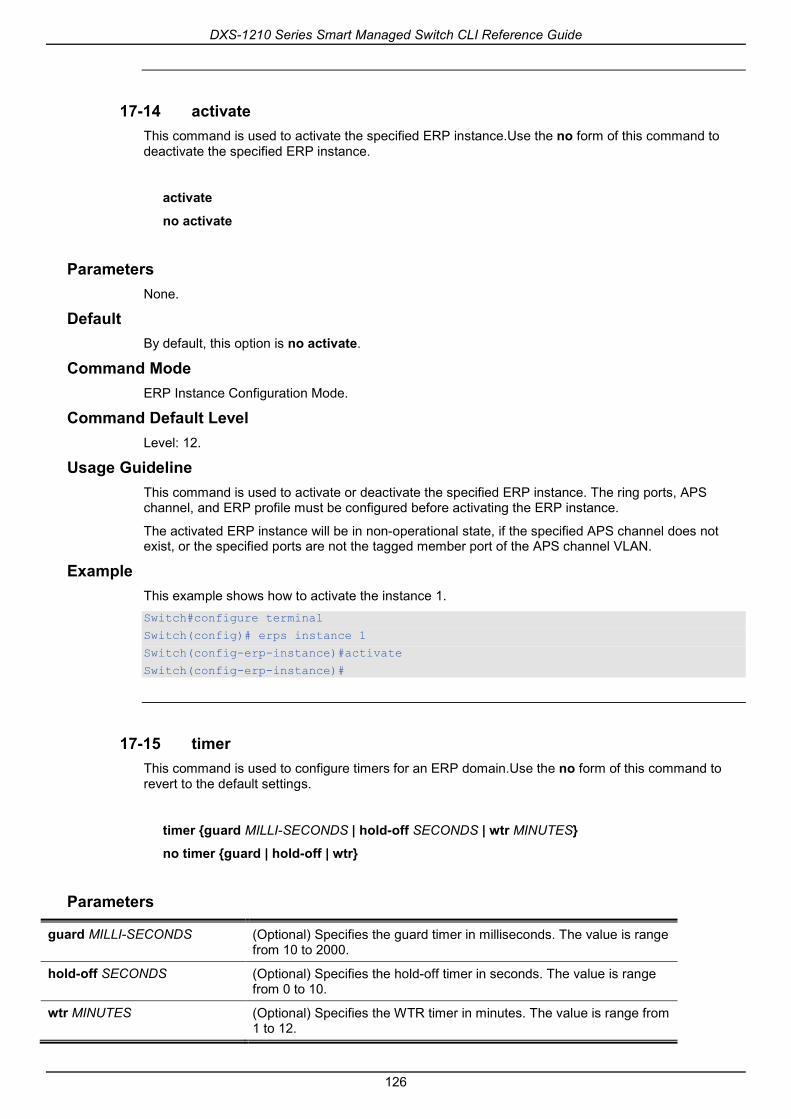
DXS-1210 Series Smart Managed Switch CLI Reference Guide
126
17-14 activate This command is used to activate the specified ERP instance.Use the no form of this command to deactivate the specified ERP instance.
activate
no activate
Parameters None.
Default By default, this option is no activate.
Command Mode ERP Instance Configuration Mode.
Command Default Level Level: 12.
Usage Guideline This command is used to activate or deactivate the specified ERP instance. The ring ports, APS channel, and ERP profile must be configured before activating the ERP instance.
The activated ERP instance will be in non-operational state, if the specified APS channel does not exist, or the specified ports are not the tagged member port of the APS channel VLAN.
Example This example shows how to activate the instance 1. Switch#configure terminal
Switch(config)# erps instance 1
Switch(config-erp-instance)#activate
Switch(config-erp-instance)#
17-15 timer This command is used to configure timers for an ERP domain.Use the no form of this command to revert to the default settings.
timer {guard MILLI-SECONDS | hold-off SECONDS | wtr MINUTES}
no timer {guard | hold-off | wtr}
Parameters
guard MILLI-SECONDS (Optional) Specifies the guard timer in milliseconds. The value is range from 10 to 2000.
hold-off SECONDS (Optional) Specifies the hold-off timer in seconds. The value is range from 0 to 10.
wtr MINUTES (Optional) Specifies the WTR timer in minutes. The value is range from 1 to 12.
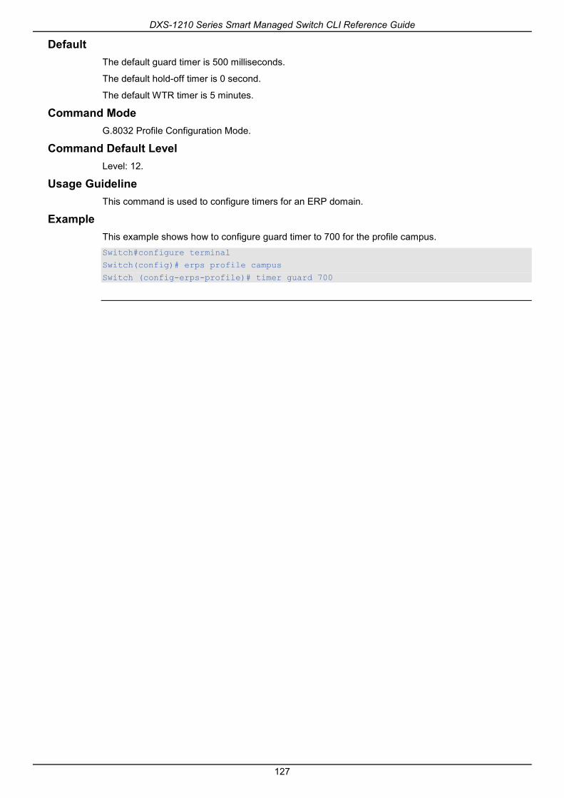
DXS-1210 Series Smart Managed Switch CLI Reference Guide
127
Default The default guard timer is 500 milliseconds.
The default hold-off timer is 0 second.
The default WTR timer is 5 minutes.
Command Mode G.8032 Profile Configuration Mode.
Command Default Level Level: 12.
Usage Guideline This command is used to configure timers for an ERP domain.
Example This example shows how to configure guard timer to 700 for the profile campus. Switch#configure terminal
Switch(config)# erps profile campus
Switch (config-erps-profile)# timer guard 700
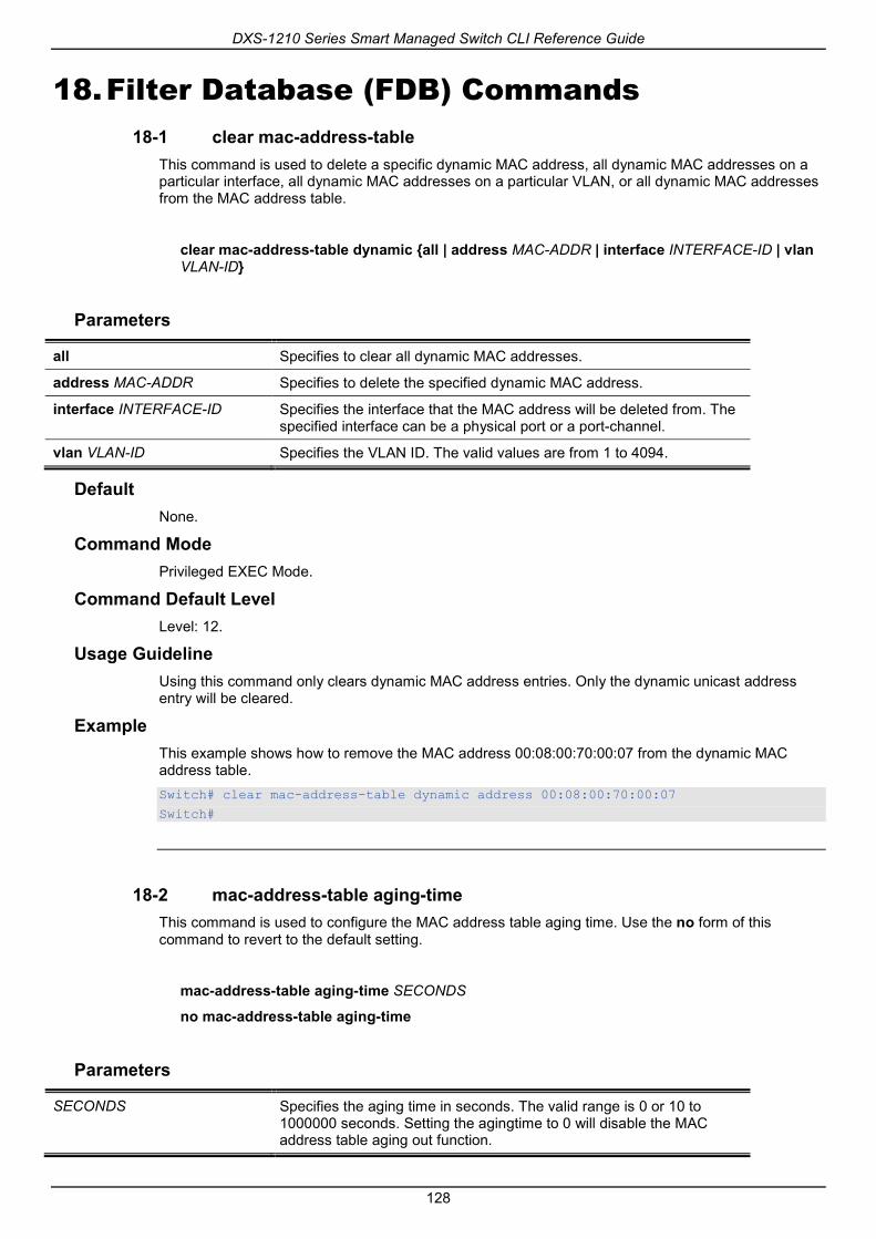
DXS-1210 Series Smart Managed Switch CLI Reference Guide
128
18. Filter Database (FDB) Commands 18-1 clear mac-address-table
This command is used to delete a specific dynamic MAC address, all dynamic MAC addresses on a particular interface, all dynamic MAC addresses on a particular VLAN, or all dynamic MAC addresses from the MAC address table.
clear mac-address-table dynamic {all | address MAC-ADDR | interface INTERFACE-ID | vlan VLAN-ID}
Parameters
all Specifies to clear all dynamic MAC addresses.
address MAC-ADDR Specifies to delete the specified dynamic MAC address.
interface INTERFACE-ID Specifies the interface that the MAC address will be deleted from. The specified interface can be a physical port or a port-channel.
vlan VLAN-ID Specifies the VLAN ID. The valid values are from 1 to 4094.
Default None.
Command Mode Privileged EXEC Mode.
Command Default Level Level: 12.
Usage Guideline Using this command only clears dynamic MAC address entries. Only the dynamic unicast address entry will be cleared.
Example This example shows how to remove the MAC address 00:08:00:70:00:07 from the dynamic MAC address table. Switch# clear mac-address-table dynamic address 00:08:00:70:00:07
Switch#
18-2 mac-address-table aging-time This command is used to configure the MAC address table aging time. Use the no form of this command to revert to the default setting.
mac-address-table aging-time SECONDS
no mac-address-table aging-time
Parameters
SECONDS Specifies the aging time in seconds. The valid range is 0 or 10 to 1000000 seconds. Setting the agingtime to 0 will disable the MAC address table aging out function.

DXS-1210 Series Smart Managed Switch CLI Reference Guide
129
Default By default, this value is 300 seconds.
Command Mode Global Configuration Mode.
Command Default Level Level: 12.
Usage Guideline Setting the aging time to 0 will disable the MAC address table aging out function.
Example This example shows how to set the aging time value to 200 seconds. Switch# configure terminal
Switch(config)#mac-address-table aging-time 200
Switch(config)#
18-3 mac-address-table aging destination-hit This command is used to enable the destination MAC address triggered update function. Use the no form of this command to disable the destination MAC address triggered updated function.
mac-address-table aging destination-hit
no mac-address-table aging destination-hit
Parameters None.
Default By default, this option is disabled.
Command Mode Global Configuration Mode.
Command Default Level Level: 12.
Usage Guideline The source MAC address triggered update function is always enabled. The hit bit of MAC address entries corresponding to the port that receives the packet will be updated based on the source MAC address and the VLAN of the packet. When the user enables the destination MAC address triggered update function by using the mac-address-table aging destination-hit command, the hit bit of MAC address entries corresponding to the port that transmit the packet will be updated based on the destination MAC address and the VLAN of the packet.
The destination MAC address triggered update function increases the MAC address entries hit bit update frequency and reduce traffic flooding by the MAC address entries aging time-out.
Example This example shows how to enable the destination MAC address triggered update function. Switch# configure terminal
Switch(config)#mac-address-table aging destination-hit
Switch(config)#
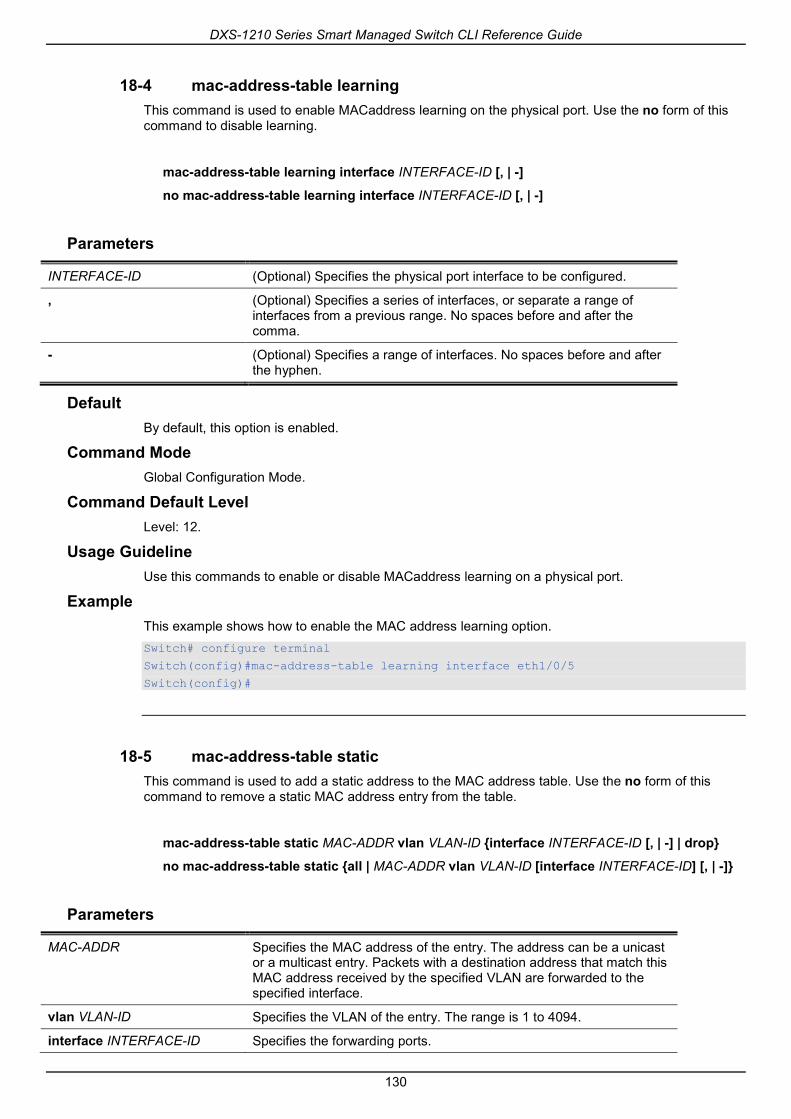
DXS-1210 Series Smart Managed Switch CLI Reference Guide
130
18-4 mac-address-table learning This command is used to enable MACaddress learning on the physical port. Use the no form of this command to disable learning.
mac-address-table learning interface INTERFACE-ID [, | -]
no mac-address-table learning interface INTERFACE-ID [, | -]
Parameters
INTERFACE-ID (Optional) Specifies the physical port interface to be configured.
, (Optional) Specifies a series of interfaces, or separate a range of interfaces from a previous range. No spaces before and after the comma.
- (Optional) Specifies a range of interfaces. No spaces before and after the hyphen.
Default By default, this option is enabled.
Command Mode Global Configuration Mode.
Command Default Level Level: 12.
Usage Guideline Use this commands to enable or disable MACaddress learning on a physical port.
Example This example shows how to enable the MAC address learning option. Switch# configure terminal
Switch(config)#mac-address-table learning interface eth1/0/5
Switch(config)#
18-5 mac-address-table static This command is used to add a static address to the MAC address table. Use the no form of this command to remove a static MAC address entry from the table.
mac-address-table static MAC-ADDR vlan VLAN-ID {interface INTERFACE-ID [, | -] | drop}
no mac-address-table static {all | MAC-ADDR vlan VLAN-ID [interface INTERFACE-ID] [, | -]}
Parameters
MAC-ADDR Specifies the MAC address of the entry. The address can be a unicast or a multicast entry. Packets with a destination address that match this MAC address received by the specified VLAN are forwarded to the specified interface.
vlan VLAN-ID Specifies the VLAN of the entry. The range is 1 to 4094.
interface INTERFACE-ID Specifies the forwarding ports.

DXS-1210 Series Smart Managed Switch CLI Reference Guide
131
, (Optional)Specifies a series of interfaces, or separate a range of interfaces from a previous range. No spacesare allowed before and after the comma.
- (Optional)Specifies a range of interfaces. No spacesare allowed before and after the hyphen.
drop Specifies to drop the frames that are sent by or sent to the specified MAC address on the specified VLAN.
all Specifies to remove all static MAC address entries.
Default None.
Command Mode Global Configuration Mode.
Command Default Level Level: 12.
Usage Guideline For a unicast MAC address entry, only one interface can be specified. For a multicast MAC address entry, multiple interfaces can be specified. To delete a unicast MAC address entry, there is no need to specify the interface ID. To delete a multicast MAC address entry, if an interface ID is specified, only this interface will be removed. Otherwise, the entire multicast MAC entry will be removed. The option drop can only be specified for a unicast MAC address entry.
Example This example shows how to add the static address C2:F3:22:0A:12:F4 to the MAC address table. It also specifies that when any packet received on VLAN 4 that has a destination MAC address of C2:F3:22:0A:12:F4 will be forwarded to the Ethernet interface 1/0/1. Switch# configure terminal
Switch(config)#mac-address-table static C2:F3:22:0A:12:F4 vlan 4 interface eth1/0/1
Switch(config)#
This example shows how to add the static address C2:F3:22:0A:22:33 to the MAC address table. It also specifies that when any packet received on VLAN 4 that has a destination MAC address of C2:F3:22:0A:22:33 will be forwarded to port-channel 2. Switch# configure terminal
Switch(config)#interface range eth1/0/5-6
Switch(config-if-range)# channel-group 2 mode on
Switch(config-if-range)# exit
Switch(config)# mac-address-table static C2:F3:22:0A:22:33 vlan 4 interface port-channel2
Switch(config)#
18-6 multicast filtering-mode This command is used to configure the handling method for multicast packets for a VLAN. Use the no form of this command to revert to the default setting.
multicast filtering-mode {forward-all | forward-unregistered | filter-unregistered}
no multicast filtering-mode
Parameters

DXS-1210 Series Smart Managed Switch CLI Reference Guide
132
forward-all Specifies to flood all multicast packets based on the VLAN domain.
forward-unregistered Specifies to forward registered multicast packets based on the forwarding table and flood all unregistered multicast packets based on the VLAN domain.
filter-unregistered Specifies to forward registered packets based on the forwarding table and filter all unregistered multicast packets.
Default By default, the forward-unregistered option is enabled.
Command Mode VLAN Configuration Mode.
Command Default Level Level: 12.
Usage Guideline This filtering mode is only applied to multicast packets that are destined for addresses other than those reserved for multicast addresses.
Example This example shows how to set the multicast filtering mode on VLAN 100 to filter unregistered. Switch# configure terminal
Switch(config)#vlan 100
Switch(config-vlan)# multicast filtering-mode filter-unregistered
Switch(config-vlan)#
18-7 show mac-address-table This command is used to display a specific MAC address entry or the MAC address entries for a specific interface or VLAN.
show mac-address-table [dynamic | static] [address MAC-ADDR | interface INTERFACE-ID | vlan VLAN-ID]
Parameters
dynamic (Optional) Specifies to display dynamic MAC address table entries only.
static (Optional) Specifies to display static MAC address table entries only.
address MAC-ADDR (Optional)Specifies the 48-bit MAC address.
interface INTERFACE-ID (Optional) Specifies to display information for a specific interface. Valid interfaces include physical ports and port-channels.
vlan VLAN-ID (Optional) Specifies the VLAN ID. The valid values are from 1 to 4094.
Default None.
Command Mode EXEC Mode or Any Configuration Mode.
Command Default Level Level: 1.

DXS-1210 Series Smart Managed Switch CLI Reference Guide
133
Usage Guideline If the option interface is specified, the unicast entry that has the forwarding interface matches the specified interface will be displayed
Example This example shows how to display all the MAC address table entries for the MAC address 00-02-4b-28-c4-82. Switch# show mac-address-table address 00:02:4B:28:C4:82
VLAN MAC Address Type Ports
------ ------------------ -------- --------
1 00-02-4B-28-C4-82 Dynamic eth1/0/1
Total Entries: 1
Switch#
This example shows how to display all the static MAC address table entries. Switch# show mac-address-table static
VLAN MAC Address Type Ports
------------------------------------------
4 00-01-00-02-00-04 Static eth1/0/2
4 C2-F3-22-0A-12-F4 Static port-channel2
6 00-01-00-02-00-07 Static eth1/0/1
6 00-01-00-02-00-10 Static Drop
Total Entries : 6
Switch#
This example shows how to display all the MAC address table entries for VLAN 1. Switch# show mac-address-table vlan 1
VLAN MAC Address Type Ports
---------------------------------------------------
1 00-03-40-11-22-33 Dynamic eth1/0/2
Total Entries: 2
Switch#
18-8 show mac-address-table aging-time This command is used to display the MAC address table’s aging time.
show mac-address-table aging-time
Parameters None.
Default None.

DXS-1210 Series Smart Managed Switch CLI Reference Guide
134
Command Mode EXEC Mode or Any Configuration Mode.
Command Default Level Level: 1.
Usage Guideline This command is used to display the MAC address table’s aging time.
Example This example shows how to display the MAC address table’s aging time. Switch# show mac-address-table aging-time
Aging Time is 300 seconds.
Aging Destination Hit is disabled.
Switch#
18-9 show mac-address-table learning This command is used to display the MAC-address learning state.
show mac-address-table learning [interface INTERFACE-ID [, | -]]
Parameters
INTERFACE-ID (Optional) Specifies the interface to be display.
, (Optional) Specifies a series of interfaces, or separate a range of interfaces from a previous range. No spaces before and after the comma.
- (Optional) Specifies a range of interfaces. No spaces before and after the hyphen.
Default None.
Command Mode EXEC Mode or Any Configuration Mode.
Command Default Level Level: 1.
Usage Guideline If the interface is not specified, all existing interfaces will be displayed.
Example This example shows how to display the MACaddress learning status on all physical ports 1 to 10.

DXS-1210 Series Smart Managed Switch CLI Reference Guide
135
Switch# show mac-address-table learning interface ethernet 1/0/1-10
Port State
------------------------ --------
eth1/0/1 Enabled
eth1/0/2 Enabled
eth1/0/3 Enabled
eth1/0/4 Enabled
eth1/0/5 Enabled
eth1/0/6 Enabled
eth1/0/7 Enabled
eth1/0/8 Enabled
eth1/0/9 Enabled
eth1/0/10 Enabled
Switch#
18-10 show multicast filtering-mode This command is used to display the filtering mode for handling multicast packets that are received on an interface.
show multicast filtering-mode [interface VLAN-ID]
Parameters
interfaceVLAN-ID (Optional) Specifies the VLAN to display.
Default None.
Command Mode EXEC Mode or Any Configuration Mode.
Command Default Level Level: 1.
Usage Guideline
Example This example shows how to display the multicast filtering mode configuration for all VLANs. Switch#show multicast filtering-mode
Interface Layer 2 Multicast Filtering Mode
-------------------------------- --------------------------------
default forward-unregistered
Total Entries: 1
Switch#

DXS-1210 Series Smart Managed Switch CLI Reference Guide
136
19. IGMP Snooping Commands 19-1 clear ip igmp snooping statistics
This command is used to clear the IGMP snooping related statistics.
clear ip igmp snooping statistics {all | vlan VLAN-ID}
Parameters
all Specifies to clear IP IGMP snooping statistics for all VLANs and all ports.
vlan VLAN-ID Specifies a VLAN to clear the IP IGMP snooping statistics.
Default None.
Command Mode Privileged EXEC Mode.
Command Default Level Level: 12.
Usage Guideline This command is used to clear the IGMP snooping related statistics.
Example This example shows how to clear all IGMP Snooping statistics. Switch# clear ip igmp snooping statistics all
Switch#
19-2 ip igmp snooping This command is used to enable the IGMP snooping function on the Switch. Use the no form of this command to disable the IGMP snooping function.
ip igmp snooping
no ip igmp snooping
Parameters None.
Default IGMP snooping is disabled on all VLAN interfaces.
The IGMP snooping global state is disabled by default.
Command Mode Interface Configuration Mode.
Global Configuration Mode.
Command Default Level
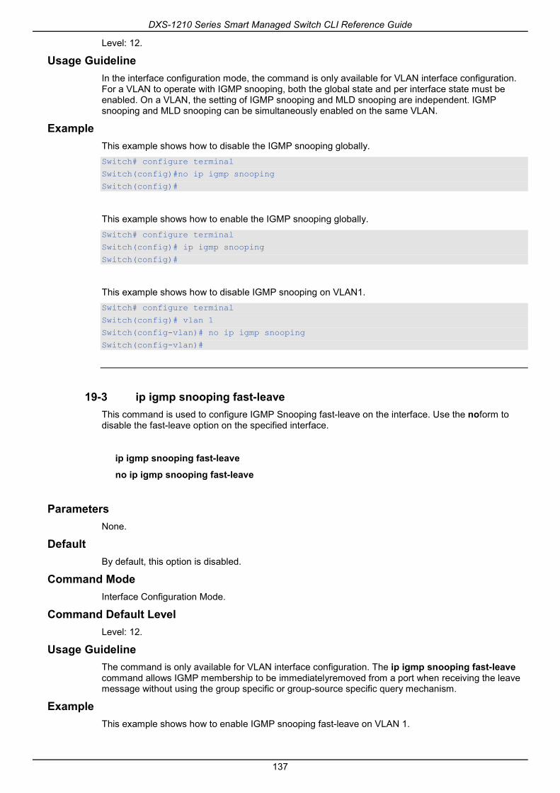
DXS-1210 Series Smart Managed Switch CLI Reference Guide
137
Level: 12.
Usage Guideline In the interface configuration mode, the command is only available for VLAN interface configuration. For a VLAN to operate with IGMP snooping, both the global state and per interface state must be enabled. On a VLAN, the setting of IGMP snooping and MLD snooping are independent. IGMP snooping and MLD snooping can be simultaneously enabled on the same VLAN.
Example This example shows how to disable the IGMP snooping globally. Switch# configure terminal
Switch(config)#no ip igmp snooping
Switch(config)#
This example shows how to enable the IGMP snooping globally. Switch# configure terminal
Switch(config)# ip igmp snooping
Switch(config)#
This example shows how to disable IGMP snooping on VLAN1. Switch# configure terminal
Switch(config)# vlan 1
Switch(config-vlan)# no ip igmp snooping
Switch(config-vlan)#
19-3 ip igmp snooping fast-leave This command is used to configure IGMP Snooping fast-leave on the interface. Use the noform to disable the fast-leave option on the specified interface.
ip igmp snooping fast-leave
no ip igmp snooping fast-leave
Parameters None.
Default By default, this option is disabled.
Command Mode Interface Configuration Mode.
Command Default Level Level: 12.
Usage Guideline The command is only available for VLAN interface configuration. The ip igmp snooping fast-leave command allows IGMP membership to be immediatelyremoved from a port when receiving the leave message without using the group specific or group-source specific query mechanism.
Example This example shows how to enable IGMP snooping fast-leave on VLAN 1.

DXS-1210 Series Smart Managed Switch CLI Reference Guide
138
Switch# configure terminal
Switch(config)#vlan 1
Switch(config-vlan)# ip igmp snooping fast-leave
Switch(config-vlan)#
19-4 ip igmp snooping last-member-query-interval This command is used to configure the interval at which the IGMP snooping querier sends IGMP group-specific or group-source-specific (channel) query messages. Use the no form of this command to revert to the default setting.
ip igmp snooping last-member-query-interval SECONDS
no ip igmp snooping last-member-query-interval
Parameters
SECONDS Specifies the maximum amount of time between group-specific query messages, including those sent in response to leave-group messages. The range of this value is 1 to 25.
Default By default, this value is 1 second.
Command Mode Interface Configuration Mode.
Command Default Level Level: 12.
Usage Guideline The command is only available for VLAN interface configuration. On receiving an IGMP leave message, the IGMP snooping querier will assume that there are no local members on the interface if there are no reports received after the response time. Users can lower this interval to reduce the amount of time it takes a switch to detect the loss of the last member of a group.
Example This example shows how to configure the last member query interval time to be 3 seconds. Switch# configure terminal
Switch(config)#vlan 1000
Switch(config-vlan)# ip igmp snooping last-member-query-interval 3
Switch(config-vlan)#
19-5 ip igmp snooping mrouter This command is used to configure the specified interface(s) as the multicast router ports or as forbidden to be multicast router ports on the Switch. Use the no form of this command to remove the interface(s) from router ports or forbidden multicast router ports.
ip igmp snooping mrouter {interface INTERFACE-ID [,|-] | forbidden interface INTERFACE-ID [,|-]}
no ip igmp snooping mrouter {interface INTERFACE-ID [,|-] | forbidden interface INTERFACE-ID [,|-]}

DXS-1210 Series Smart Managed Switch CLI Reference Guide
139
Parameters
interface Specifies a static multicast router port.
forbidden interface Specifies a port that cannot be multicast router port.
INTERFACE-ID (Optional) Specifies an interface or an interface list. The interface can be a physical interface or a port-channel.
, (Optional)Specifies a series of interfaces, or a separate a range of interfaces from a previous range. No space is allowed before and after the comma.
- (Optional)Specifies a range of interfaces. No space is allowed before and after the hyphen.
Default No IGMP snooping multicast router port is configured.
Auto-learning is enabled.
Command Mode Interface Configuration Mode.
Command Default Level Level: 12.
Usage Guideline This command is only available for VLAN interface configuration. To specify a multicast router port, the valid interface can be a physical port or a port-channel. The specified multicast router port must be member port of the configured VLAN. A multicast router port can be either dynamic learned or statically configured. With the dynamic learning, the IGMP snooping entity will learn IGMP, PIM, or DVMRP packet to identify a multicast router port.
Example This example shows how to add an IGMP snooping static multicast router port for VLAN 1. Switch# configure terminal
Switch(config)#vlan 1
Switch(config-vlan)# ip igmp snooping mrouter interface eth 1/0/1
Switch(config-vlan)#
19-6 ip igmp snooping querier This command is used to enable the capability of the entity as an IGMP querier. Use the no form of this command to disable the querier function.
ip igmp snooping querier
no ip igmp snooping querier
Parameters None.
Default By default, this option is disabled.
Command Mode Interface Configuration Mode.
Command Default Level

DXS-1210 Series Smart Managed Switch CLI Reference Guide
140
Level: 12.
Usage Guideline This command is only available for VLAN interface configuration. If the system can play the querier role, the entity will listen for IGMP query packets sent by other devices. If IGMP query message is received, the device with lower value of IP address becomes the querier.
Example This example shows how to enable the IGMP snooping querier on VLAN 1. Switch# configure terminal
Switch(config)#vlan 1
Switch(config-vlan)# ip igmp snooping querier
Switch(config-vlan)#
19-7 ip igmp snooping query-interval This command is used to configure the interval at which the IGMP snooping querier sends IGMP general query messages periodically. Use the no form of this command to revert to the default setting.
ip igmp snooping query-interval SECONDS
no ip igmp snooping query-interval
Parameters
SECONDS Specifies to configure the interval at which the designated router sends IGMP general-query messages. The range is 1 to 31744.
Default By default, this value is 125 seconds.
Command Mode Interface Configuration Mode.
Command Default Level Level: 12.
Usage Guideline This command is only available for VLAN interface configuration. The query interval is the interval between General Queries sent by the Querier. By varying the query interval, an administrator may tune the number of IGMP messages on the network; larger values cause IGMP Queries to be sent less often.
Example This example shows how to configure the IGMP snooping query interval to 300 seconds on VLAN 1000. Switch# configure terminal
Switch(config)#vlan 1000
Switch(config-vlan)# ip igmp snooping query-interval 300
Switch(config-vlan)#
19-8 ip igmp snooping query-max-response-time This command is used to configure the maximum response time advertised in IGMP snooping queries. Use the no form of this command to revert to the default setting.

DXS-1210 Series Smart Managed Switch CLI Reference Guide
141
ip igmp snooping query-max-response-time SECONDS
no ip igmp snooping query-max-response-time
Parameters
SECONDS Specifies to set the maximum response time, in seconds, advertised in IGMP snooping queries. The range is 1 to 25.
Default By default, this value is 10 seconds.
Command Mode Interface Configuration Mode.
Command Default Level Level: 12.
Usage Guideline This command is only available for VLAN interface configuration. This command configures the period of which the group member can respond to an IGMP query message before the IGMP Snooping deletes the membership.
Example This example shows how to configure the maximum response time to 20 seconds on VLAN 1000. Switch# configure terminal
Switch(config)#vlan 1000
Switch(config-vlan)# ip igmp snooping query-max-response-time 20
Switch(config-vlan)#
19-9 ip igmp snooping query-version This command is used to configure the general query packet version sent by the IGMP snooping querier. Use the no form of this command to revert to the default setting.
ip igmp snooping query-version {1 | 2 | 3}
no ip igmp snooping query-version
Parameters
NUMBER Specifies the version of the IGMP general query sent by the IGMP snooping querier.
Default By default, this value is 3.
Command Mode Interface Configuration Mode.
Command Default Level Level: 12.
Usage Guideline

DXS-1210 Series Smart Managed Switch CLI Reference Guide
142
This command is only available for VLAN interface configuration. The query version number setting will affect the querier electing. When configured to version 1, IGMP snooping will always act as the querier, and will not initiate new querier electing no matter what IGMP query packet is received. When configured to version 2 or version 3, IGMP snooping will initiate a new querier electing if any IGMPv2 or IGMPv3 query packet is received. When receiving an IGMPv1 query packet, IGMP snooping will not initiate a new querier electing.
Example This example shows how to configure the query version to be 2 on VLAN 1000. Switch# configure terminal
Switch(config)#vlan 1000
Switch(config-vlan)# ip igmp snooping query-version 2
Switch(config-vlan)#
19-10 ip igmp snooping robustness-variable This command is used to set the robustness variable used in IGMP snooping. Use the no form of this command to revert to the default value.
ip igmp snooping robustness-variable VALUE
no ip igmp snooping robustness-variable
Parameters
VALUE Specifies the robustness variable. The range is from 1 to 7.
Default By default, this value is 2.
Command Mode Interface Configuration Mode.
Command Default Level Level: 12.
Usage Guideline This command is only available for VLAN interface configuration. The robustness variable provides fine-tuning to allow for expected packet loss on an interface. The value of the robustness variable is used in calculating the following IGMP message intervals:
• Group member interval – The amount of time that must pass before a multicast router decides there are no more members of a group on a network.
This interval is calculated as follows: (robustness variable x query interval) + (1 x query response interval).
• Other querier present interval – The amount of time that must pass before a multicast router decides that there is no longer another multicast router that is the querier.
This interval is calculated as follows: (robustness variable x query interval) + (0.5 x query response interval).
• Last member query count – The number of group-specific queries sent before the router assumes there are no local members of a group. The default number is the value of the robustness variable.
Users can increase this value if a subnet is expected to be loose.
Example This example shows how to configure the robustness variable to be 3 on interface VLAN 1000.

DXS-1210 Series Smart Managed Switch CLI Reference Guide
143
Switch# configure terminal
Switch(config)#vlan 1000
Switch(config-vlan)# ip igmp snooping robustness-variable 3
Switch(config-vlan)#
19-11 ip igmp snooping static-group This command is used to configure an IGMP snooping static group. Use the no form of this command is used to delete a static group.
ip igmp snooping static-group GROUP-ADDRESS interface INTERFACE-ID [,|-]
no ip igmp snooping static-group GROUP-ADDRESS [interface INTERFACE-ID [,|-]]
Parameters
GROUP-ADDRESS Specifies an IP multicast group address.
INTERFACE-ID (Optional) Specifies an interface or an interface list. The interface can be a physical interface or a port-channel.
, (Optional) Specifies a series of interfaces, or a separate a range of interfaces from a previous range. No space is allowed before and after the comma.
- (Optional) Specifies a range of interfaces. No space is allowed before and after the hyphen.
Default By default, no static-group is configured.
Command Mode Interface Configuration Mode.
Command Default Level Level: 12.
Usage Guideline This command is only available for VLAN interface configuration. This command applies to IGMP snooping on a VLAN interface to statically add group membership entries.
The ip igmp snooping static-group command allows the user to create an IGMP snooping static group in case that the attached host does not support the IGMP protocol.
Example This example shows how to statically add a group for IGMP snooping. Switch# configure terminal
Switch(config)#vlan 1
Switch(config-vlan)# ip igmp snooping static-group 226.1.2.3 interface eth 1/0/5
Switch(config-vlan)#
19-12 show ip igmp snooping This command is used to display IGMP snooping information on the Switch.
show ip igmp snooping [vlan VLAN-ID]

DXS-1210 Series Smart Managed Switch CLI Reference Guide
144
Parameters
vlan VLAN-ID (Optional) Specifies the VLAN to be displayed.
Default None.
Command Mode EXEC Mode or Any Configuration Mode.
Command Default Level Level: 1.
Usage Guideline Use this command to display IGMP snooping information for all VLANs where IGMP snooping is enabled.
Example This example shows how to display IGMP snooping global state. Switch#show ip igmp snooping
IGMP snooping global state: Enabled
Switch#
This example shows how to display IGMP snooping information on VLAN 2. Switch#show ip igmp snooping vlan 2
IGMP snooping state : Disabled
Fast leave : Enabled (host-based)
Querier state : Enabled (Non-active)
Query version : v2
Query interval : 300 seconds
Max response time : 20 seconds
Robustness value : 2
Last member query interval : 3 seconds
Switch#
19-13 show ip igmp snooping groups This command is used to display IGMP snooping group information learned on the Switch.
show ip igmp snooping groups [vlan VLAN-ID | IP-ADDRESS]
Parameters
vlan VLAN-ID (Optional) Specifies the VLAN interface to be displayed. If no VLAN is specified, IGMP snooping group information of all VLANs will be displayed, at which IGMP Snooping is enabled.
IP-ADDRESS (Optional) Specifies the group IP address to be displayed. If no IP address is specified, all IGMP group information will be displayed.

DXS-1210 Series Smart Managed Switch CLI Reference Guide
145
Default None.
Command Mode EXEC Mode or Any Configuration Mode.
Command Default Level Level: 1.
Usage Guideline Use this command to display IGMP snooping group information.
Example This example shows how to display IGMP snooping group information. Switch# show ip igmp snooping groups
IGMP Snooping Connected Group Membership:
VLAN ID Group address Source address Exp(sec) Interface
------- --------------- --------------- -------- ---------
1 239.255.255.250 * 382 2/0/7
Total Entries: 1
Switch#
19-14 show ip igmp snooping mrouter This command is used to display IGMP snooping router port information learned and configured on the Switch.
show ip igmp snooping mrouter [vlan VLAN-ID]
Parameters
vlan VLAN-ID (Optional) Specifies the VLAN. If no VLAN is specified, IGMP snooping information on all VLANs will be displayed of which IGMP snooping is enabled.
Default None.
Command Mode EXEC Mode or Any Configuration Mode.
Command Default Level Level: 1.
Usage Guideline Use this command to display dynamically learned or manually configured multicast router interfaces.
Example This example shows how to display IGMP snooping router port information.

DXS-1210 Series Smart Managed Switch CLI Reference Guide
146
Switch# show ip igmp snooping mrouter
VLAN Ports
-------- ----------------------------------
1 3/0/3-3/0/4 (static)
3/0/6 (forbidden)
4/0/2 (dynamic)
2 4/0/4 (static)
4/0/3 (dynamic)
Total Entries: 2
Switch#
19-15 show ip igmp snooping static-group This command is used to display IGMP snooping statistics group information on the Switch.
show ip igmp snooping static-group [GROUP-ADDRESS | vlan VLAN-ID]
Parameters
GROUP-ADDRESS (Optional) Specifies the group IP address to be displayed.
vlan VLAN-ID (Optional) Specifies the VLAN ID to be displayed.
Default None.
Command Mode EXEC Mode or Any Configuration Mode.
Command Default Level Level: 1.
Usage Guideline This command displays the IGMP snooping static group information.
Example This example shows how to display IGMP snooping static group information. Switch#show ip igmp snooping static-group
VLAN ID Group address Interface
------- --------------- ------------------------
2 226.1.2.2 1/0/3
Total Entries: 1
Switch#
19-16 show ip igmp snooping statistics This command is used to display IGMP snooping statistics information on the Switch.

DXS-1210 Series Smart Managed Switch CLI Reference Guide
147
show ip igmp snooping statistics vlan [VLAN-ID]
Parameters
vlan VLAN-ID Specifies the VLAN ID to display VLAN statistics.
Default None.
Command Mode EXEC Mode or Any Configuration Mode.
Command Default Level Level: 1.
Usage Guideline This command displays the IGMP snooping related statistics information.
Example This example shows how to display IGMP snooping statistics information. Switch# show ip igmp snooping statistics vlan 1
VLAN 1 Statistics:
IGMPv1 Rx: Report 1, Query 0
IGMPv2 Rx: Report 0, Query 0, Leave 0
IGMPv3 Rx: Report 0, Query 0
IGMPv1 Tx: Report 0, Query 0
IGMPv2 Tx: Report 0, Query 0, Leave 0
IGMPv3 Tx: Report 0, Query 0
Total Entries: 1
Switch#

DXS-1210 Series Smart Managed Switch CLI Reference Guide
148
20. Interface Commands 20-1 clear counters
This command is used to clear counters for a physical port interface.
clear counters {all | interface INTERFACE-ID [,|-]}
Parameters
all Specifies to clear counters for all interfaces.
INTERFACE-ID Specifies the interface ID to clear the counter.
Default None.
Command Mode Privileged EXEC Mode.
Command Default Level Level: 12.
Usage Guideline Use this command to clear counters for a physical port interface.
Example This example shows how to clear the counters of interface eth1/0/1. Switch# clear counters interface eth 1/0/1
Switch#
20-2 description This command is used to add a description to an interface.
description STRING
no description
Parameters
STRING Specifies a description for an interface with a maximum of 64 characters.
Default None.
Command Mode Interface Configuration Mode.
Command Default Level Level: 12.
Usage Guideline
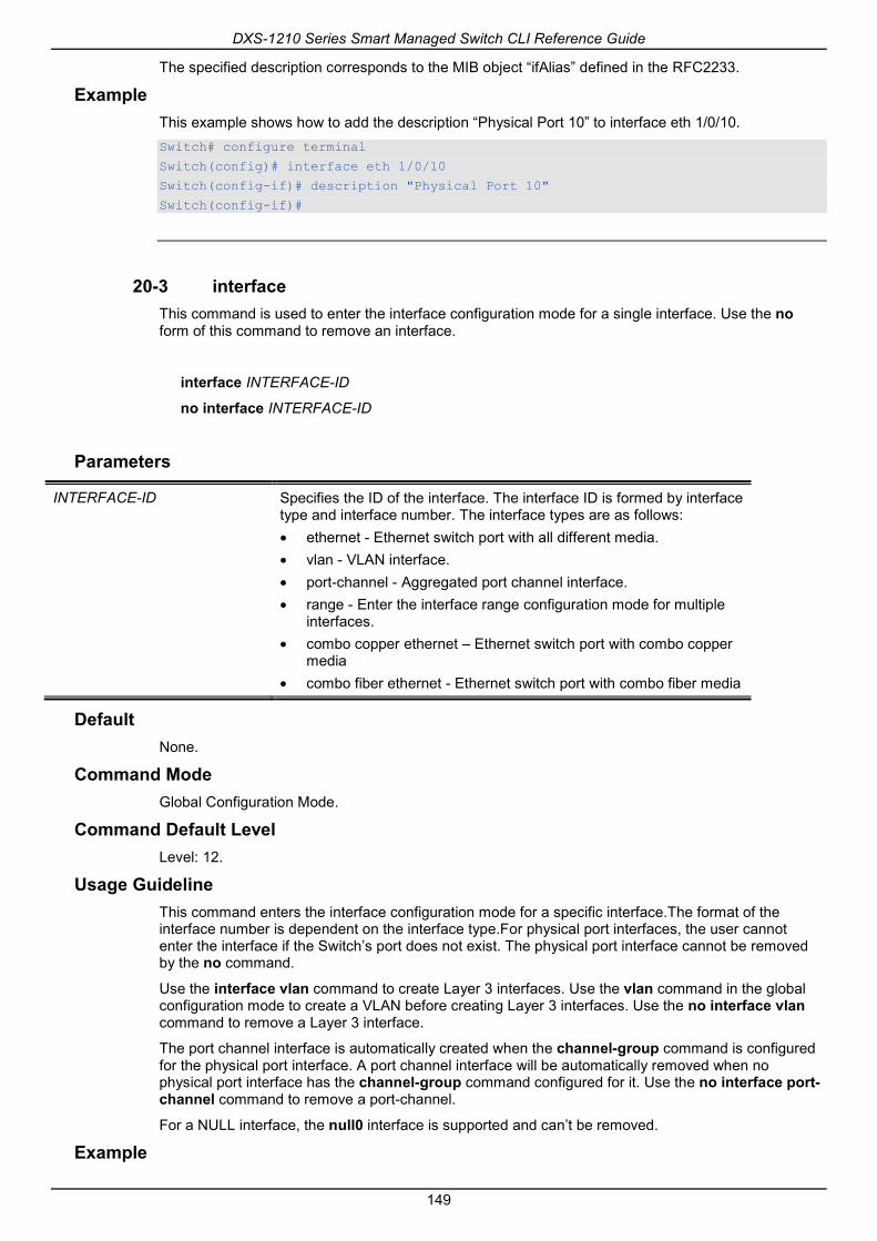
DXS-1210 Series Smart Managed Switch CLI Reference Guide
149
The specified description corresponds to the MIB object “ifAlias” defined in the RFC2233.
Example This example shows how to add the description “Physical Port 10” to interface eth 1/0/10. Switch# configure terminal
Switch(config)# interface eth 1/0/10
Switch(config-if)# description "Physical Port 10"
Switch(config-if)#
20-3 interface This command is used to enter the interface configuration mode for a single interface. Use the no form of this command to remove an interface.
interface INTERFACE-ID
no interface INTERFACE-ID
Parameters
INTERFACE-ID Specifies the ID of the interface. The interface ID is formed by interface type and interface number. The interface types are as follows: • ethernet - Ethernet switch port with all different media. • vlan - VLAN interface. • port-channel - Aggregated port channel interface. • range - Enter the interface range configuration mode for multiple
interfaces. • combo copper ethernet – Ethernet switch port with combo copper
media • combo fiber ethernet - Ethernet switch port with combo fiber media
Default None.
Command Mode Global Configuration Mode.
Command Default Level Level: 12.
Usage Guideline This command enters the interface configuration mode for a specific interface.The format of the interface number is dependent on the interface type.For physical port interfaces, the user cannot enter the interface if the Switch’s port does not exist. The physical port interface cannot be removed by the no command.
Use the interface vlan command to create Layer 3 interfaces. Use the vlan command in the global configuration mode to create a VLAN before creating Layer 3 interfaces. Use the no interface vlan command to remove a Layer 3 interface.
The port channel interface is automatically created when the channel-group command is configured for the physical port interface. A port channel interface will be automatically removed when no physical port interface has the channel-group command configured for it. Use the no interface port-channel command to remove a port-channel.
For a NULL interface, the null0 interface is supported and can’t be removed.
Example

DXS-1210 Series Smart Managed Switch CLI Reference Guide
150
This example shows how to enter the interface configuration mode for the interface eth 1/0/5. Switch# configure terminal
Switch(config)#interface eth 1/0/5
Switch(config-if)#
This example shows how to enter the interface configuration mode for VLAN 100. Switch# configure terminal
Switch(config)#interface vlan 100
Switch(config-if)#
This example shows how to enter interface configuration mode for port channel 3. Switch# configure terminal
Switch(config)#interface port-channel 3
Switch(config-if)#
This example shows how to enter combo rj45 port interface configuration mode for the interface eth 1/0/11
Switch# configure terminal
Switch(config)# interface combo copper ethernet 1/0/11
Switch(config-if-combo)#
20-4 interface range This command is used to enter the interface range configuration mode for multiple interfaces.
interface [combo {copper | fiber }] range INTERFACE-ID [, | -]
Parameters
INTERFACE-ID Specifies the physical port interface.
, (Optional)Specifies the interface range by delimiting a list of interface IDs with commas. No spacesare allowed before and after the comma.
- (Optional) Specifies an interface range by delimiting the start and the ending interface numbers with a hyphen. No spacesare allowed before and after the hyphen.
Default None.
Command Mode Global Configuration Mode.
Command Default Level Level: 12.
Usage Guideline This command enters the interface configuration mode for the specified range of interfaces. Commands configured in the interface range mode, applies to interfaces in the range.
Example This example shows how to enter the interface configuration mode for the range of ports 1/0/1 to 1/0/5: and port 1/0/7.

DXS-1210 Series Smart Managed Switch CLI Reference Guide
151
Switch# configure terminal
Switch(config)# interface range ethernet 1/0/2-5,1/0/7
Switch(config-if-range)#
This example shows how to enter combo sfp port interface configuration mode for the range of ports 1/0/11 to 1/0/12
Switch# configure terminal
Switch(config)# interface combo fiber range ethernet 1/0/11-12
Switch(config-if-combo-range)#
20-5 show counters This command is used to display interface information.
show counters [interface INTERFACE-ID]
Parameters
INTERFACE-ID Specifies that the interface can be a physical port. If no interface is specified, counters of all interfaces will be displayed.
Default None.
Command Mode EXEC Mode or Any Configuration Mode.
Command Default Level Level: 1.
Usage Guideline Use this command to display the statistic counters for an interface.
Example This example shows how to display the counters for interface eth1/0/1.

DXS-1210 Series Smart Managed Switch CLI Reference Guide
152
Switch#show counter interface eth 1/0/1
eth1/0/1 counters
rxHCTotalPkts : 1176
txHCTotalPkts : 348
rxHCUnicastPkts : 0
txHCUnicastPkts : 0
rxHCMulticastPkts : 755
txHCMulticastPkts : 0
rxHCBroadcastPkts : 421
txHCBroadcastPkts : 348
rxHCOctets : 112581
txHCOctets : 126324
rxHCPkt64Octets : 21
rxHCPkt65to127Octets : 982
rxHCPkt128to255Octets : 173
rxHCPkt256to511Octets : 0
rxHCPkt512to1023Octets : 0
rxHCPkt1024to1518Octets : 0
rxHCPkt1519to1522Octets : 0
rxHCPkt1519to2047Octets : 0
rxHCPkt2048to4095Octets : 0
rxHCPkt4096to9216Octets : 0
txHCPkt64Octets : 0
txHCPkt65to127Octets : 0
txHCPkt128to255Octets : 0
txHCPkt256to511Octets : 348
txHCPkt512to1023Octets : 0
txHCPkt1024to1518Octets : 0
txHCPkt1519to1522Octets : 0
txHCPkt1519to2047Octets : 0
txHCPkt2048to4095Octets : 0
txHCPkt4096to9216Octets : 0
rxCRCAlignErrors : 0
rxUndersizedPkts : 0
rxOversizedPkts : 0
rxFragmentPkts : 0
rxJabbers : 0
rxSymbolErrors : 0
rxMulticastDropPkts : 0
rxMTUDropPkts : 0
ifInErrors : 0
ifOutErrors : 0
ifInDiscards : 1175
ifInUnknownProtos : 0
ifOutDiscards : 0
txDelayExceededDiscards : 0
dot3StatsAlignmentErrors : 0
dot3StatsFCSErrors : 0
dot3StatsSingleColFrames : 0
dot3StatsMultiColFrames : 0
dot3StatsSQETestErrors : 0
dot3StatsDeferredTransmisions : 0
dot3StatsLateCollisions : 0

DXS-1210 Series Smart Managed Switch CLI Reference Guide
153
dot3StatsExcessiveCollisions : 0
dot3StatsInternalMacTransmitErrors : 0
dot3StatsCarrierSenseErrors : 0
dot3StatsInternalMacReceiveErrors : 0
linkChange : 1
Switch#
20-6 show interfaces This command is used to display the interface information.
show interfaces [INTERFACE-ID [- | ,]]
Parameters
INTERFACE-ID (Optional) Specifies that the interface can be a physical port, VLAN, or other.
Default None.
Command Mode EXEC Mode or Any Configuration Mode.
Command Default Level Level: 1.
Usage Guideline If no interfaceis specified, all existing physical ports will be displayed.
Example This example shows how to display the interface information for eth1/0/1.

DXS-1210 Series Smart Managed Switch CLI Reference Guide
154
Switch#show interfaces eth1/0/1
Eth1/0/1 is enabled, link status is up
Interface type: 1000BASE-T
Interface description:
MAC Address: 00-01-02-03-04-01
Auto-duplex, auto-speed, auto-mdix
Send flow-control: off, receive flow-control: off
Send flow-control oper: off, receive flow-control oper: off
Full-duplex, 1Gb/s
Maximum transmit unit: 1536 bytes
Rx rate: 0 bytes/sec, TX rate: 0 bytes/sec
RX bytes: 116316, TX bytes: 132495
RX rate: 0 packets/sec, TX rate: 0 packets/sec
RX packets: 1213, TX packets: 365
RX multicast: 774, RX broadcast: 439
RX CRC error: 0, RX undersize: 0
RX oversize: 0, RX fragment: 0
RX jabber: 0, RX dropped Pkts: 1212
RX MTU exceeded: 0, TX excessive deferral: 0
TX single collision: 0, TX excessive collision: 0
TX late collision: 0
Switch#
20-7 show interfaces counters This command is used to display counters on specified interfaces.
show interfaces [INTERFACE-ID [,|-]] counters [errors]
Parameters
errors (Optional) Specifies to display the error counters.
INTERFACE-ID (Optional) Specifies that the interface can be a physical port. If no interface is specified, the counters on all interfaces will be displayed.
Default None.
Command Mode EXEC Mode or Any Configuration Mode.
Command Default Level Level: 1.
Usage Guideline This command allows the user to display switch port statistics counters.
Example This example shows how to display switch port counters on ports 1 to 8.

DXS-1210 Series Smart Managed Switch CLI Reference Guide
155
Switch#show interfaces ethernet 1/0/1-8 counters
Port InOctets / InMcastPkts /
InUcastPkts InBcastPkts
------------- ---------------------- ----------------------
eth1/0/1 1834520 629
9234 338
eth1/0/2 0 0
0 0
eth1/0/3 0 0
0 0
eth1/0/4 0 0
0 0
eth1/0/5 0 0
0 0
eth1/0/6 0 0
0 0
eth1/0/7 0 0
0 0
eth1/0/8 0 0
0 0
Port OutOctets / OutMcastPkts /
OutUcastPkts OutBcastPkts
------------- ---------------------- ----------------------
eth1/0/1 5387265 0
9381 0
eth1/0/2 0 0
0 0
eth1/0/3 0 0
0 0
eth1/0/4 0 0
0 0
eth1/0/5 0 0
0 0
eth1/0/6 0 0
0 0
eth1/0/7 0 0
0 0
eth1/0/8 0 0
0 0
Total Entries:8
Switch#
This example shows how to display switch ports error counters.

DXS-1210 Series Smart Managed Switch CLI Reference Guide
156
Switch#
Switch# show interfaces ethernet 1/0/1-8 counters errors
Port Align-Err Fcs-Err UnderSize OutDiscard Carri-Sen
--------- -------- --------- ---------- ---------- -------
eth1/0/1 0 0 0 0 0
eth1/0/2 0 0 0 0 0
eth1/0/3 0 0 0 0 0
eth1/0/4 0 0 0 0 0
eth1/0/5 0 0 0 0 0
eth1/0/6 0 0 0 0 0
eth1/0/7 0 0 0 0 0
eth1/0/8 0 0 0 0 0
Port Single-Col Multi-Col Late-Col Excess-Col SQETest-Err
--------- -------- --------- ---------- ---------- ------
eth1/0/1 0 0 0 0 0
eth1/0/2 0 0 0 0 0
eth1/0/3 0 0 0 0 0
eth1/0/4 0 0 0 0 0
eth1/0/5 0 0 0 0 0
eth1/0/6 0 0 0 0 0
eth1/0/7 0 0 0 0 0
eth1/0/8 0 0 0 0 0
Port DeferredTx IntMacTx IntMacRx
--------- ---------- -------- ----------
eth1/0/1 0 0 0
eth1/0/2 0 0 0
eth1/0/3 0 0 0
eth1/0/4 0 0 0
eth1/0/5 0 0 0
eth1/0/6 0 0 0
eth1/0/7 0 0 0
eth1/0/8 0 0 0
total entries: 8
Switch#
20-8 show interfaces status This command is used to display the Switch’s port connection status.
show interfaces [INTERFACE-ID [,|-]] status
Parameters
INTERFACE-ID (Optional) Specifies the interface ID. If no interface is specified, the connection status of all switch ports will be displayed.
Default None.
Command Mode

DXS-1210 Series Smart Managed Switch CLI Reference Guide
157
EXEC Mode or Any Configuration Mode.
Command Default Level Level: 1.
Usage Guideline This command displaysthe Switch’s port connection status.
Example This example shows how to display the Switch’s port connection status. Switch# show interfaces ethernet 1/0/1-8 status
Port Status MAC Address VLAN Duplex Speed
Type
----------- -------------- ------------------ ----- ---------- -----------
---------
eth1/0/1 Not-Connected 00-00-04-01-02-02 1 Auto Auto
10GBASE-T
eth1/0/2 Not-Connected 00-00-04-01-02-03 1 Auto Auto
10GBASE-T
eth1/0/3 Not-Connected 00-00-04-01-02-04 1 Auto Auto
10GBASE-T
eth1/0/4 Not-Connected 00-00-04-01-02-05 1 Auto Auto
10GBASE-T
eth1/0/5 Connected 00-00-04-01-02-06 1 Auto-Full Auto-1000M
10GBASE-T
eth1/0/6 Not-Connected 00-00-04-01-02-07 1 Auto Auto
10GBASE-T
eth1/0/7 Not-Connected 00-00-04-01-02-08 1 Auto Auto
10GBASE-T
eth1/0/8 Not-Connected 00-00-04-01-02-09 1 Auto Auto
10GBASE-T
20-9 shutdown This command is used to disable an interface. Use the no form of this command to enable an interface.
shutdown
no shutdown
Parameters None.
Default By default, this option is no shutdown.
Command Mode Interface Configuration Mode.
Command Default Level Level: 12.
Usage Guideline

DXS-1210 Series Smart Managed Switch CLI Reference Guide
158
The physical port is valid for this configuration. This command is also configurable for port channel member ports.
The command will cause the port to enter the disabled state. Under the disabled state, the port will not be able to receive or transmit any packets. Using the no shutdown command will put the port back into the enabled state. When a port is shut down, the link status will also be turned off.
Example This example shows how to enter the shutdown command to disable the port state of interface port 1/0/1. Switch# configure terminal
Switch(config)# interface eth 1/0/1
Switch(config-if)# shutdown

DXS-1210 Series Smart Managed Switch CLI Reference Guide
159
21. IP Utility Commands 21-1 ping
This command is used to diagnose basic network connectivity.
ping {IP-ADDRESS | IPV6-ADDRESS [VLAN-ID]} [count TIMES] [timeout SECONDS] [source {IP-ADDRESS | IPV6-ADDRESS}]
Parameters
IP-ADDRESS Specifies the IPv4 address of the destination host.
IPV6-ADDRESS Specifies the IPv6 address of the system to discover.
VLAN-ID (Optional) The ip address vlan ID to get the interface index
count TIMES (Optional) Specifies to stop after sending the specified number of echo request packets.
timeout SECONDS (Optional) Specifies response timeout value, in seconds.
source {IP-ADDRESS | IPV6-ADDRESS}
Specifies the source IP address used for the ping packet. The specified IP address must one of the IP address configured for the Switch. The destination address and the source IP must be the same type of address, both are IPv4 or IPv6.
Default If the timeout parameter is not specified, the timeout value will be 1 second.
Command Mode EXEC Mode.
Command Default Level Level: 1.
Usage Guideline Use this command to verify the reachability, reliability, and delay of the path to the destination host. If neither the count or timeout value is specified, the only way to stop the ping is by pressing Ctrl+C.
Example This example shows how to ping the host with IP address 211.21.180.1 with count 4 times. Switch#ping 211.21.180.1 count 4
Reply from 211.21.180.1, time=10ms
Reply from 211.21.180.1, time<10ms
Reply from 211.21.180.1, time<10ms
Reply from 211.21.180.1, time<10ms
Ping Statistics for 211.21.180.1
Packets: Sent =4, Received =4, Lost =0
Switch#
This example shows how to ping the host with IPv6 address 2001:238:f8a:77:7c10:41c0:6ddd:ecab.

DXS-1210 Series Smart Managed Switch CLI Reference Guide
160
Switch# ping 2001:238:f8a:77:7c10:41c0:6ddd:ecab
Reply from 2001:238:f8a:77:7c10:41c0:6ddd:ecab , bytes=100, time<10 ms
Reply from 2001:238:f8a:77:7c10:41c0:6ddd:ecab , bytes=100, time<10 ms
Reply from 2001:238:f8a:77:7c10:41c0:6ddd:ecab , bytes=100, time<10 ms
Reply from 2001:238:f8a:77:7c10:41c0:6ddd:ecab , bytes=100, time<10 ms
Ping Statistics for 2001:238:f8a:77:7c10:41c0:6ddd:ecab
Packets: Sent =4, Received =4, Lost =0
Switch#

DXS-1210 Series Smart Managed Switch CLI Reference Guide
161
22. Jumbo Frame Commands 22-1 max-rcv-frame-size
This command is used to configure the maximum Ethernet frame size allowed. Use the no form of this command to revert to the default setting.
max-rcv-frame-size BYTES
no max-rcv-frame-size
Parameters
BYTES Specifies the maximum Ethernet frame size allowed.
Default By default, this value is 1536 bytes.
Command Mode Interface Configuration Mode.
Command Default Level Level: 12.
Usage Guideline This command is available for physical ports configuration. Oversize frames will be dropped and checks are carried out on ingress ports. Use this command to transfer large frames or jumbo frames through the switch system to optimize server-to-server performance.
Example This example shows how to configure the maximum received Ethernet frame size to be 6000 bytes on port 4/0/1. Switch# configure terminal
Switch(config)#interface eth4/0/1
Switch(config-if)# max-rcv-frame-size 6000
Switch(config-if)#

DXS-1210 Series Smart Managed Switch CLI Reference Guide
162
23. Link Aggregation Control Protocol (LACP) Commands
23-1 channel-group This command is used to assign an interface to a channel group. Use the no form of this command to remove an interface from a channel-group.
channel-group CHANNEL-NO mode {on | active | passive}
no channel-group
Parameters
CHANNEL-NO Specifies the channel group ID. The valid range is 1 to 8.
on Specifies that the interface is a static member of the channel-group.
active Specifies the interface to operate in LACP active mode.
passive Specifies the interface to operate in LACP passive mode.
Default None.
Command Mode Interface Configuration Mode.
Command Default Level Level: 12.
Usage Guideline The command is available for physical port interface configuration. The system will automatically create the port-channel when a physical port first joins a channel group. An interface can only join one channel-group.
If the mode on is specified in the command, the channel group type is static. If the mode active or passive is specified in the command, the channel group type is LACP. A channel group can only consist of either static members or LACP members. Once the type of channel group has been determined, other types of interfaces cannot join the channel group.
Use the no form of this command to remove the interface from the channel group. If the channel group has no member ports left after a port is removed, the channel group will be deleted automatically. A port channel can also be removed by the no interface port-channel command.
If the security function is enabled on a port, then this port cannot be specified as a channel group member.
Example This example shows how to assign Ethernet interfaces 1/0/4 to 1/0/5 to a new LACP channel-group, with an ID of 3, and sets the LACP mode to active. Switch# configure terminal
Switch(config)#interface range eth 1/0/4-5
Switch(config-if)# channel-group 3 mode active
Switch(config-if)#

DXS-1210 Series Smart Managed Switch CLI Reference Guide
163
23-2 lacp port-priority This command is used to configure the port priority. Use the no form of this command to revert the port priority to the default settings.
lacp port-priority PRIORITY
no lacp port-priority
Parameters
PRIORITY Specifies the port priority. The range is 1 to 65535.
Default The default port-priority is 32768.
Command Mode Interface Configuration Mode.
Command Default Level Level: 12.
Usage Guideline The LACP port-priority determines which ports can join a port-channel and which ports are put in the standalone mode. The lower value has a higher priority. If two or more ports have the same priority, the port number determines the priority
Example This example shows how to configure the port priority to 20000 on interfaces 1/0/4 to 1/0/5. Switch# configure terminal
Switch(config)#interface range eth 1/0/4-5
Switch(config-if)# lacp port-priority 20000
Switch(config-if)#
23-3 lacp timeout This command is used to configure the LACP long or short timer. Use the no form of this command to return to the default value.
lacp timeout {short | long}
no lacp timeout
Parameters
short Specifies that there will be 3 seconds before invalidating received LACPDU information. Once the partner recognizes this information in the received PDU, LACP PDU periodic transmissions will be sent at 1 second intervals.
long Specifies that there will be 90 seconds before invalidating received LACPDU information.Once the partner recognizes this information in the received PDU, LACP PDU periodic transmissions will be sent at30 second intervals.
Default By default, the LACP timeout mode is long.

DXS-1210 Series Smart Managed Switch CLI Reference Guide
164
Command Mode Interface Configuration Mode.
Command Default Level Level: 12.
Usage Guideline This command is available for physical port interface configuration.
Example This example shows how to configure the port LACP timeout to long mode on Ethernet interface 1/0/1. Switch# configure terminal
Switch(config)#interface eth 1/0/1
Switch(config-if)# lacp timeout long
Switch(config-if)#
23-4 lacp system-priority This command is used to configure the system priority. Use the no form of this command to revert the system priority back to the default value.
lacp system-priority PRIORITY
no lacp system-priority
Parameters
PRIORITY Specifies the system priority. The range is 1 to 65535.
Default The default LACP system-priority is 32768.
Command Mode Global Configuration Mode.
Command Default Level Level: 12.
Usage Guideline During LACP negotiation, the system priority and port priority of the local partner will be exchanged with the remote partner. When the maximum number of actual members exceeds the limitation, the Switch will use port priority to determine whether a port is operating in a backup mode or in an active mode. The LACP system-priority determines the Switch that controls the port priority. Port priorities on the other switch are ignored.
The lower value has a higher priority. If two switches have the same system priority, the LACP system ID (MAC) determines the priority. The LACP system priority command applies to all LACP port-channels on the Switch.
Example This example shows how to configure the LACP system priority to be 30000. Switch# configure terminal
Switch(config)#lacp system-priority 30000
Switch(config)#

DXS-1210 Series Smart Managed Switch CLI Reference Guide
165
23-5 port-channel load-balance This command is used to configure the load balance algorithm that the Switch uses to distribute packets across ports in the same channel. Use the no form of this command to revert to the default setting.
port-channel load-balance {dst-ip | dst-mac | src-dst-ip | src-dst-mac | src-ip | src-mac}
no port-channel load-balance
Parameters
dst-ip Specifies that the Switch should examine the IP destination address.
dst-mac Specifies that the Switch should examine the MAC destination address.
src-dst-ip Specifies that the Switch should examine the IP source address and IP destination address.
src-dst-mac Specifies that the Switch should examine the MAC source and MAC destination address.
src-ip Specifies that the Switch should examine the IP source address.
src-mac Specifies that the Switch should examine the MAC source address.
Default The default load balance algorithm is src-mac.
Command Mode Global Configuration Mode.
Command Default Level Level: 12.
Usage Guideline Use this command to specify the load balance algorithm. Only one algorithm can be specified.
Example This example shows how to configure the load balance algorithm as src-ip. Switch# configure terminal
Switch(config)#port-channel load-balance src-ip
Switch(config)#
23-6 show channel-group This command is used to display the channel group information.
show channel-group [channel [CHANNEL-NO] {detail | neighbor} | load-balance | sys-id]
Parameters
CHANNEL-NO (Optional) Specifies the channel group ID.
channel (Optional) Specifies to display information for the specified port-channels.
detail (Optional) Specifies to display detailed channel group information.

DXS-1210 Series Smart Managed Switch CLI Reference Guide
166
neighbor (Optional) Specifies to display neighbor information.
load-balance (Optional) Specifies to display the load balance information.
sys-id (Optional) Specifies to display the system identifier that is being used by LACP.
Default None.
Command Mode EXEC Mode or Any Configuration Mode.
Command Default Level Level: 1.
Usage Guideline If a port-channel number is not specified, all port-channels will be displayed. If the channel, load-balance and sys-id keywords are not specified with the show channel-group command, only summary channel-group information will be displayed.
Example This example shows how to display the detailed information of all port-channels.

DXS-1210 Series Smart Managed Switch CLI Reference Guide
167
24. Link Layer Discovery Protocol (LLDP) Commands
24-1 clear lldp counters This command is used to delete LLDP statistics.
clear lldp counters [all | interface INTERFACE-ID [, | -]]
Parameters
all Specifies to clear LLDP counter information for all interfaces and global LLDP statistics.
interface INTERFACE-ID Specifies the interface to clear LLDP counter information.
, (Optional) Specifies a series of physical interfaces. No spaces before and after the comma.
- (Optional) Specifies a range of physical interfaces. No spaces before and after the hyphen.
Default None.
Command Mode Privileged EXEC Mode.
Command Default Level Level: 12.
Usage Guideline Use this command with the interface keyword to reset LLDP statistics of the specified interface(s). If the command clear lldp counters is issued with the all keyword to clear global LLDP statistics and the LLDP statistics on all interfaces.When no optional keyword is selected, only the LLDP global counters will be cleared.
Example This example shows how to clear LLDP statistics. Switch# clear lldp counters all
Switch#
This example shows how to clear port of LLDP statistics. Switch# clear lldp counters interface ethernet 1/0/1
Switch#
24-2 clear lldp table This command is used to delete all LLDP information learned from neighboring devices.
clear lldp table {all | interface INTERFACE-ID [, | -]}
Parameters

DXS-1210 Series Smart Managed Switch CLI Reference Guide
168
all Specifies to clear LLDP neighboring information for all interfaces.
INTERFACE-ID Specifies the interface’s ID.
, (Optional) Specifies a series of physical interfaces. No spacesbefore and after the comma.
- (Optional) Specifies a range of physical interfaces. No spaces before and after the hyphen.
Default None.
Command Mode Privileged EXEC Mode.
Command Default Level Level: 12.
Usage Guideline If this command is issued without the interface keyword, all neighboring information on all interfaces will be cleared.
Example This example shows how to clear all neighboring information on all interfaces. Switch# clear lldp table all
Switch#
This example shows how to clear neighboring information on interface. Switch# clear lldp table interface ethernet 1/0/1
Switch#
24-3 lldp dot1-tlv-select This command is used to specify which optional type-length-value settings (TLVs) in the IEEE 802.1 Organizationally Specific TLV set will be transmitted and encapsulated in the LLDPDUs and sent to neighbor devices. Use the no form of this commandto disable the transmissionof TLVs.
lldp dot1-tlv-select {port-vlan | vlan-name [VLAN-ID [, | -]] | protocol-identity [PROTOCOL-NAME]}
no lldp dot1-tlv-select {port-vlan | vlan-name [VLAN-ID [, | -]] | protocol-identity [PROTOCOL-NAME]}
Parameters
port-vlan Specifies the port VLAN ID TLV to send. The Port VLAN ID TLV is an optional fixed length TLV that allows a VLAN bridge port to advertise the port’s VLAN identifier (PVID) that will be associated with untagged or priority tagged frames.
vlan-name Specifies the VLAN name TLV to send. The VLAN name TLV is an optional TLV that allows an IEEE 802.1Q-compatible IEEE 802 LAN station to advertise the assigned name of any VLAN with which it is configured.
VLAN-ID [, | -] (Optional) Specifies the ID of the VLAN in the VLAN name TLV. The VLAN ID range is 1 to 4094. Separate nonconsecutive VLAN ID with a comma. Use a hyphen to designate a range of VLAN IDs. If no VLAN

DXS-1210 Series Smart Managed Switch CLI Reference Guide
169
ID is specified, all applicable VLANs will be sent. In the no form of this command, if no VLAN ID is specified, all configured VLANs for the VLAN name TLV will be cleared and no VLAN name TLV will be sent.
protocol-identity [PROTOCOL-NAME]
Specifies the Protocol Identity TLV to send. The Protocol Identity TLV is an optional TLV that allows an IEEE 802 LAN station to advertise particular protocols that are accessible through the port. The valid strings for PROTOCOL-NAME are: eapol: Extensible Authentication Protocol (EAP) over LAN lacp: Link Aggregation Control Protocol gvrp: GARP VLAN Registration Protocol stp: Spanning Tree Protocol The protocol name is optional. When no specific protocol string is specified, all protocols are selected or de-selected in the no form of the command.
Default No IEEE 802.1 Organizationally Specific TLV is selected.
Command Mode Interface Configuration Mode.
Command Default Level Level: 12.
Usage Guideline This command is available for physical port configurations. If the optional TLVs advertisement state is enabled, they will be encapsulated in LLDPDUs and sent to other devices.
The protocol identity TLV optional data type indicates whether to advertise the corresponding local system's protocol identity instance on the port. The protocol identity TLV provides a way for devices to advertise protocols that are important to the operation of the network. For example, protocols like Spanning Tree Protocol, Link Aggregation Control Protocol, and numerous vendor proprietary variations are responsible for maintaining the topology and connectivity of the network. When both of the protocol functions are working and the protocol identity is enabled for advertising on a port, the protocol identity TLV will be advertised.
Only when the configured VLAN ID matches the configuration of the protocol VLAN on that interface and the VLAN exists, then the PPVID TLV for that VLAN will be sent. Only when the interface is a member port of the configured VLAN ID, the VLAN will be advertised in VLAN Name TLV.
Example This example shows how to enable advertising Port VLAN ID TLV. Switch# configure terminal
Switch(config)# interface eth 1/0/1
Switch(config-if)# lldp dot1-tlv-select port-vlan
Switch(config-if)#
This example shows how to enable the VLAN Name TLV advertisement from vlan1 to vlan3. Switch# configure terminal
Switch(config)#interface eth 1/0/1
Switch(config-if)#lldp dot1-tlv-select vlan-name 1-3
Switch(config-if)#
This example shows how to enable the LACP Protocol Identity TLV advertisement.

DXS-1210 Series Smart Managed Switch CLI Reference Guide
170
Switch# configure terminal
Switch(config)# interface eth 1/0/1
Switch(config-if)# lldp dot1-tlv-select protocol-identity lacp
Switch(config-if)#
24-4 lldp dot3-tlv-select This command is used to specify which optional type-length-value settings (TLVs) in the IEEE 802.3 Organizationally Specific TLV set will encapsulated in the LLDPDUs and sent to neighbor devices.Use the no form of this commandto disable the transmission of the TLVs.
lldp dot3-tlv-select [mac-phy-cfg | link-aggregation | power |max-frame-size]
no lldp dot3-tlv-select [mac-phy-cfg | link-aggregation | power |max-frame-size]
Parameters
mac-phy-cfg (Optional) Specifies the MAC/PHY Configuration/Status TLV to send. The MAC/PHY Configuration/Status TLV is an optional TLV that identifies (1) the duplex and bit-rate capability of the sending IEEE 802.3 LAN node, and (2) the current duplex and bit-rate settings of the sending IEEE 802.3 LAN node.
link-aggregation (Optional) Specifies the Link Aggregation TLV to send. The Link Aggregation TLV indicates contains the following information. Whether the link is capable of being aggregated, whether the link is currently in an aggregation, and the aggregated port channel ID of the port. If the port is not aggregated, then the ID is 0.
power (Optional)Specifies the power via MDI TLV to send. Three IEEE 802.3 PMD implementations (10BASE-T, 100BASE-TX and 1000BASE-T) allow power to be supplied over the link for connected non-powered systems. The Power Via MDI TLV allows network management to advertise and discover the MDI power support capabilities of the sending IEEE 802.3 LAN station.
max-frame-size (Optional) Specifies the Maximum Frame Size TLV to send. The Maximum Frame Size TLV indicates the maximum frame size capability of the implemented MAC and PHY.
Default No IEEE 802.3 Organizationally Specific TLV is selected.
Command Mode Interface Configuration Mode.
Command Default Level Level: 12.
Usage Guideline This command is available for physical port configuration. This command enables the advertisement of the optional IEEE 802.3 Organizationally Specific TLVs. The respective TLV will be encapsulated in LLDPDU and sent to other devices if the advertisement state is enabled.
Example This example shows how to enable the advertising MAC/PHY Configuration/Status TLV.

DXS-1210 Series Smart Managed Switch CLI Reference Guide
171
Switch# configure terminal
Switch(config)# interface eth 1/0/1
Switch(config-if)# lldp dot3-tlv-select mac-phy-cfg
Switch(config-if)#
24-5 lldp fast-count This command is used to configure the LLDP-MED fast start repeat count option on the Switch.Use the no form of this command to revert to the default setting.
lldp fast-count VALUE
no lldp fast-count
Parameters
VALUE Specifies the LLDP-MED fast start repeat count value. This value must be between 1 and 10.
Default By default, this value is 4.
Command Mode Global Configuration Mode.
Command Default Level Level: 12.
Usage Guideline When an LLDP-MED Capabilities TLV is detected, the application layer will start the fast start mechanism. This command is used to configure the fast start repeat count which indicates the number of LLDP message transmissions for one complete fast start interval.
Example This example shows how to configure the LLDP MED fast start repeat count. Switch# configure terminal
Switch(config)#lldp fast-count 10
Switch(config)#
24-6 lldp hold-multiplier This command is used to configure the hold multiplier for LLDP updates on the Switch. Use the no form of this command to revert to the default setting.
lldp hold-multiplier VALUE
no hold-multiplier
Parameters
VALUE Specifies the multiplier on the LLDPDUs transmission interval that used to compute the TTL value of an LLDPDU. This value must be between 2 and 10.

DXS-1210 Series Smart Managed Switch CLI Reference Guide
172
Default By default, this value is 4.
Command Mode Global Configuration Mode.
Command Default Level Level: 12.
Usage Guideline This parameter is a multiplier on the LLDPDUs transmission interval that is used to compute the TTL value in an LLDPDU. The lifetime is determined by the hold-multiplier times the TX-interval. At the partner switch, when the TTL for a given advertisement expires, the advertised data is deleted from the neighbor switch’s MIB.
Example This example shows how to configure the LLDP hold-multiplier to 3. Switch# configure terminal
Switch(config)#lldp hold-multiplier 3
Switch(config)#
24-7 lldp management-address This command is used to configure the management address that will be advertised on the physical interface. Use the no form of this command to remove the settings.
lldp management-address [IP-ADDRESS | IPV6-ADDRESS]
no lldp management-address [IP-ADDRESS | IPV6-ADDRESS]
Parameters
IP-ADDRESS (Optional) Specifies the IPv4 address that is carried in the management address TLV.
IPV6-ADDRESS (Optional) Specifies the IPv6 address that is carried in the management address TLV.
Default No LLDP management address is configured (no Management Address TLV is sent).
Command Mode Interface Configuration Mode.
Command Default Level Level:12.
Usage Guideline This command is available for physical port configuration. This command specifies the IPv4/IPv6 address that is carried in the management address TLV on the specified port. If an IP address is specified, but the address is not one of the addresses of the system interfaces, then the address will not be sent.
When no optional address is specified along with the command lldp management-address, the Switch will find least one IPv4 and IPv6 address of the VLAN with the smallest VLAN ID. If no applicable IPv4/IPv6 address exists, then no management address TLV will be advertised. Once the administrator configures an address, both of the default IPv4 and IPv6 management address will become inactive and won’t be sent. The default IPv4 or IPv6 address will be active again when all the

DXS-1210 Series Smart Managed Switch CLI Reference Guide
173
configured addresses are removed. Multiple IPv4/IPv6 management addresses can be configured by using this command multiple times.
Use the no lldp management-address command without a management address to disable the management address adverted in LLDPDUs. If there is no effective management address in the list, no Management Address TLV will be sent.
Example This example shows how to enable eth1/0/1 and eth1/0/2 for setting the management address entry (IPv4). Switch# configure terminal
Switch(config)#interface range eth 1/0/1-1/0/2
Switch(config-if-range)# lldp management-address 10.1.1.1
Switch(config-if-range)#
This example shows how to enable eth3/0/3 and eth3/0/4 for setting the management address entry (IPv6). Switch# configure terminal
Switch(config)#interface range eth 1/0/3-1/0/4
Switch(config-if-range)# lldp management-address FE80::250:A2FF:FEBF:A056
Switch(config-if-range)#
This example shows how to delete the management address 10.1.1.1 from eth3/0/1 and eth3/0/2. If 10.1.1.1 is the last one, no Management Address TLV will be sent. Switch# configure terminal
Switch(config)#interface range eth 1/0/1-1/0/2
Switch(config-if-range)# no lldp management-address 10.1.1.1
Switch(config-if-range)#
This example shows how to delete the management address FE80::250:A2FF:FEBF:A056 from eth3/0/3. and eth3/0/4. Switch# configure terminal
Switch(config)#interface range eth 1/0/3-1/0/4
Switch(config-if-range)# no lldp management-address FE80::250:A2FF:FEBF:A056
Switch(config-if-range)#
This example shows how to delete all management addresses from eth3/0/5 and then no Management Address TLV will be sent on eth3/0/5. Switch# configure terminal
Switch(config)#interface eth 1/0/5
Switch(config-if)# no lldp management-address
Switch(config-if)#
24-8 lldp med-tlv-select This command is used to specify which optional LLDP-MED TLV will be transmitted and encapsulated in the LLDPDUs and sent to neighbor devices. Use the no form of this commandto disable the transmission of the TLVs.
lldp med-tlv-select [capabilities | inventory-management]
no lldp med-tlv-select [capabilities | inventory-management]

DXS-1210 Series Smart Managed Switch CLI Reference Guide
174
Parameters
capabilities (Optional) Specifies to transmit the LLDP-MED capabilities TLV.
inventory-management (Optional) Specifies to transmit the LLDP-MED inventory management TLV.
Default No LLDP-MED TLV is selected.
Command Mode Interface Configuration Mode.
Command Default Level Level: 12.
Usage Guideline This command is available for physical port configuration. This command is used to enable or disable transmitting LLDP-MED TLVs.
When disabling the transmission of the Capabilities TLV, LLDP-MED on the physical interface will be disabled at the same time. In other words, all LLDP-MED TLVs will not be sent, even when other LLDP-MED TLVs are enabled to transmit.
By default, the Switch only sends LLDP packets until it receives LLDP-MED packets from the end device. The Switch continues to send LLDP-MED packets until it only receives LLDP packets.
Example This example shows how to enable transmitting LLDP-MED TLVs and LLDP-MED Capabilities TLVs. Switch# configure terminal
Switch(config)#interface ethernet 1/0/1
Switch(config-if)# lldp med-tlv-select capabilities
Switch(config-if)#
24-9 lldp receive This command is used to enable a physical interface to receive LLDP messages. Use the no form of this command to disable receiving LLDP messages.
lldp receive
no lldp receive
Parameters None.
Default LLDP is enabled on all supported interfaces.
Command Mode Interface Configuration Mode.
Command Default Level Level: 12.
Usage Guideline This command is available for physical port configuration. This command is used to enable a physical interface to receive LLDP messages. When LLDP is not running, the Switchdoes not receive LLDP messages.

DXS-1210 Series Smart Managed Switch CLI Reference Guide
175
Example This example shows how to enable a physical interface to receive LLDP messages. Switch# configure terminal
Switch(config)#interface ethernet 1/0/1
Switch(config-if)# lldp receive
Switch(config-if)#
24-10 lldp reinit This command is used to configure the minimum time of re-initialization the delay interval on the Switch. Use the no form of this command to revert to the default setting.
lldp reinit SECONDS
no lldp reinit
Parameters
SECONDS Specifies the delay value for LLDP initialization on an interface. This value must be between 1 and 10 seconds.
Default By default, this value is 2 seconds.
Command Mode Global Configuration Mode.
Command Default Level Level: 12.
Usage Guideline A re-enabled LLDP physical interface will wait for the re-initialization delay after the last disable command before reinitializing.
Example This example shows how to configure the re-initialization delay interval to 5 seconds. Switch# configure terminal
Switch(config)#lldp reinit 5
Switch(config)#
24-11 lldp run This command is used to enable the Link Layer Discovery Protocol (LLDP) globally. Use the no form of this command to revert to the default setting.
lldp run
no lldp run
Parameters None.
Default

DXS-1210 Series Smart Managed Switch CLI Reference Guide
176
By default, this option is disabled.
Command Mode Global Configuration Mode.
Command Default Level Level: 12.
Usage Guideline Use this command to globally enable LLDP and then the Switch can start to transmit LLDP packets and receive and process the LLDP packets. However, the transmission and receiving of LLDP can be controlled respectively by the lldp transmit command and the lldp receive command in the interface configuration mode. LLDP takes effect on a physical interface only when it is enabled both globally and on the physical interface.
By advertising LLDP packets, the Switch announces the information to its neighbor through physical interfaces. On the other hand, the Switch will learn the connectivity and management information from the LLDP packets advertised from the neighbor(s).
Example This example shows how to enable LLDP. Switch# configure terminal
Switch(config)#lldp run
Switch(config)#
24-12 lldp forward This command is used to enable the LLDP forwarding state. Use the no form of this command to revert to the default settings.
lldp forward
no lldp forward
Parameters None.
Default By default, this option is disabled.
Command Mode Global Configuration Mode.
Command Default Level Level: 12.
Usage Guideline This is a global control for the LLDP forward. When the LLDP global state is disabled and LLDP forwarding is enabled, the received LLDPDU packet will be forwarded.
Example This example shows how to enable the LLDP global forwarding state. Switch# configure terminal
Switch(config)# lldp forward
Switch(config)#
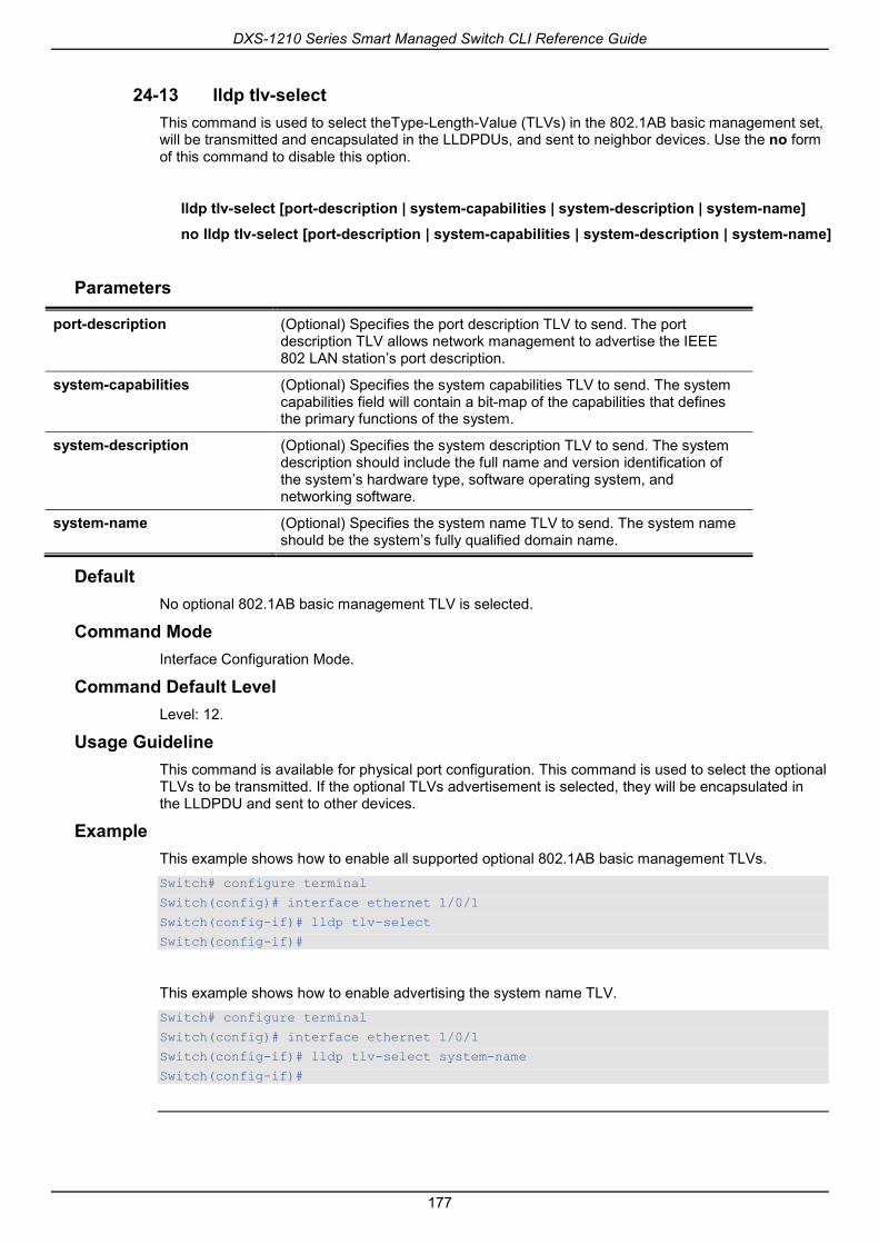
DXS-1210 Series Smart Managed Switch CLI Reference Guide
177
24-13 lldp tlv-select This command is used to select theType-Length-Value (TLVs) in the 802.1AB basic management set, will be transmitted and encapsulated in the LLDPDUs, and sent to neighbor devices. Use the no form of this command to disable this option.
lldp tlv-select [port-description | system-capabilities | system-description | system-name]
no lldp tlv-select [port-description | system-capabilities | system-description | system-name]
Parameters
port-description (Optional) Specifies the port description TLV to send. The port description TLV allows network management to advertise the IEEE 802 LAN station’s port description.
system-capabilities (Optional) Specifies the system capabilities TLV to send. The system capabilities field will contain a bit-map of the capabilities that defines the primary functions of the system.
system-description (Optional) Specifies the system description TLV to send. The system description should include the full name and version identification of the system’s hardware type, software operating system, and networking software.
system-name (Optional) Specifies the system name TLV to send. The system name should be the system’s fully qualified domain name.
Default No optional 802.1AB basic management TLV is selected.
Command Mode Interface Configuration Mode.
Command Default Level Level: 12.
Usage Guideline This command is available for physical port configuration. This command is used to select the optional TLVs to be transmitted. If the optional TLVs advertisement is selected, they will be encapsulated in the LLDPDU and sent to other devices.
Example This example shows how to enable all supported optional 802.1AB basic management TLVs. Switch# configure terminal
Switch(config)# interface ethernet 1/0/1
Switch(config-if)# lldp tlv-select
Switch(config-if)#
This example shows how to enable advertising the system name TLV. Switch# configure terminal
Switch(config)# interface ethernet 1/0/1
Switch(config-if)# lldp tlv-select system-name
Switch(config-if)#
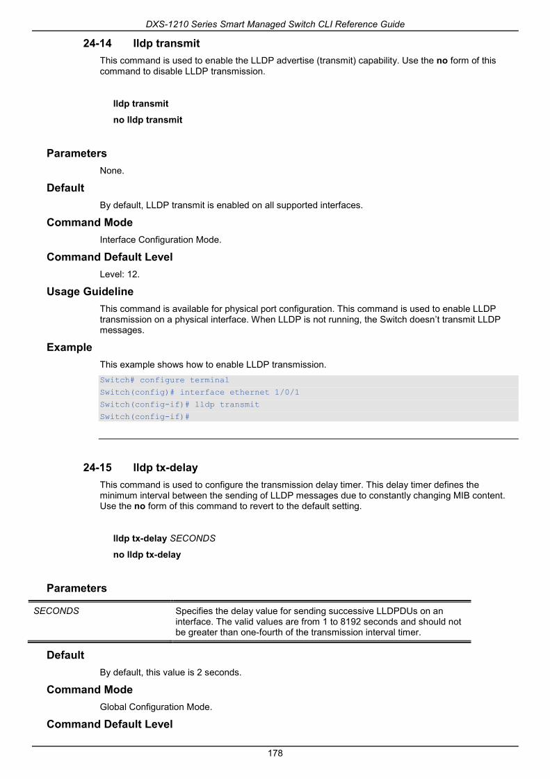
DXS-1210 Series Smart Managed Switch CLI Reference Guide
178
24-14 lldp transmit This command is used to enable the LLDP advertise (transmit) capability. Use the no form of this command to disable LLDP transmission.
lldp transmit
no lldp transmit
Parameters None.
Default By default, LLDP transmit is enabled on all supported interfaces.
Command Mode Interface Configuration Mode.
Command Default Level Level: 12.
Usage Guideline This command is available for physical port configuration. This command is used to enable LLDP transmission on a physical interface. When LLDP is not running, the Switch doesn’t transmit LLDP messages.
Example This example shows how to enable LLDP transmission. Switch# configure terminal
Switch(config)# interface ethernet 1/0/1
Switch(config-if)# lldp transmit
Switch(config-if)#
24-15 lldp tx-delay This command is used to configure the transmission delay timer. This delay timer defines the minimum interval between the sending of LLDP messages due to constantly changing MIB content. Use the no form of this command to revert to the default setting.
lldp tx-delay SECONDS
no lldp tx-delay
Parameters
SECONDS Specifies the delay value for sending successive LLDPDUs on an interface. The valid values are from 1 to 8192 seconds and should not be greater than one-fourth of the transmission interval timer.
Default By default, this value is 2 seconds.
Command Mode Global Configuration Mode.
Command Default Level

DXS-1210 Series Smart Managed Switch CLI Reference Guide
179
Level: 12.
Usage Guideline The LLDP transmission interval must be greater than or equal to four times of the transmission delay timer.
Example This example shows how to configure the transmission delay timer to 8 seconds. Switch# configure terminal
Switch(config)#lldp tx-delay 8
Switch(config)#
24-16 lldp tx-interval This command is used to configure the LLDPDUs transmission interval on the Switch. Use the no form of this command to revert to the default setting.
lldp tx-interval SECONDS
no lldp tx-interval
Parameters
SECONDS Specifies the interval between consecutive transmissions of LLDP advertisements on each physical interface. The range is from 5 to 32768 seconds.
Default By default, this value is 30 seconds.
Command Mode Global Configuration Mode.
Command Default Level Level: 12.
Usage Guideline This interval controls the rate at which LLDP packets are sent.
Example This example shows how to configurethat LLDP updates are sent every 50 seconds. Switch# configure terminal
Switch(config)#lldp tx-interval 50
Switch(config)#
24-17 snmp-server enable traps lldp This command is used to enable the LLDP and LLDP-MED trap state.
snmp-server enable traps lldp [med]
no snmp-server enable traps lldp [med]

DXS-1210 Series Smart Managed Switch CLI Reference Guide
180
Parameters
med (Optional) Specifies to enable the LLDP-MED trap state.
Default The LLDP and LLDP-MED trap statesare disabled.
Command Mode Global Configuration Mode.
Command Default Level Level: 12.
Usage Guideline Use the snmp-server enable traps lldp command to enable the sending of LLDP notifications.
Use the snmp-server enable traps lldp med command to enable the sending of LLDP-MED notifications.
Example This example shows how to enable the LLDP MED trap. Switch# configure terminal
Switch(config)#snmp-server enable traps lldp med
Switch(config)#
24-18 lldp subtype This command is used to configure the subtype of LLDP TLV(s).
lldp subtype port-id {mac-address | local}
Parameters
port-id Specifies the subtype of the port ID TLV.
mac-address Specifies the subtype of the port ID TLV to “MAC Address (3)” and the field of “port ID” will be encoded with the MAC address.
local Specifies the subtype of the port ID TLV to use “Locally assigned (7)” and the field of “port ID” will be encoded with the port number.
Default The subtype of port ID TLV is local (port number).
Command Mode Interface Configuration Mode.
Command Default Level Level: 12.
Usage Guideline Use this command to specify the subtype of LLDP TLV(s). A port ID subtype is used to indicate how the port is being referenced in the port ID field.
Example This example shows how to configure the subtype of the port ID TLV to mac-address.

DXS-1210 Series Smart Managed Switch CLI Reference Guide
181
Switch# configure terminal
Switch(config)# interface ethernet 1/0/1
Switch(config-if)# lldp subtype port-id mac-address
Switch(config-if)#
24-19 show lldp This command is used to display the Switch’s general LLDP configuration.
show lldp
Parameters None.
Default None.
Command Mode EXEC Mode or Any Configuration Mode.
Command Default Level Level: 1.
Usage Guideline This command is used to display the LLDP system’s global configurations.
Example This example shows how to display the LLDP system’s global configuration status.

DXS-1210 Series Smart Managed Switch CLI Reference Guide
182
Switch#show lldp
LLDP System Information
Chassis ID Subtype : MAC Address
Chassis ID : 3C-1E-04-A1-CC-00
System Name : Switch
System Description : Gigabit Ethernet SmartPro Switch
System Capabilities Supported: Repeater, Bridge
System Capabilities Enabled : Repeater, Bridge
LLDP-MED System Information:
Device Class : Network Connectivity Device
Hardware Revision : A1
Firmware Revision : 1.00.012
Software Revision : 1.30.003
Serial Number :
Manufacturer Name : D-Link Corporation
Model Name : DXS-1210-28XMP Gigabit Ethernet
Asset ID :
PoE Device Type : PSE Device
PoE PSE Power Source : Primary
LLDP Configurations
LLDP State : Disabled
LLDP Forward State : Disabled
Message TX Interval : 30
CTRL+C ESC q Quit SPACE n Next Page ENTER Next Entry a All
24-20 show lldp interface This command is used to display the LLDP configuration at the physical interface.
show lldp interface INTERFACE-ID[, | -]
Parameters
INTERFACE-ID Specifies to display the LLDP configuration for a specific interface. Valid interfaces are physical interfaces.
, (Optional) Specifies a series of physical interfaces. No spaces before and after the comma.
- (Optional) Specifies a range of physical interfaces. No spaces before and after the hyphen.
Default None.
Command Mode EXEC Mode or Any Configuration Mode.
Command Default Level Level: 1.
Usage Guideline This command displays the LLDP information of each physical interface.
Example

DXS-1210 Series Smart Managed Switch CLI Reference Guide
183
This example shows how to display a specific physical interface’s LLDP configuration. Switch#show lldp interface ethernet 1/0/1
Port ID: eth1/0/1
------------------------------------------------------------------------------
Port ID :eth1/0/1
Admin Status :TX and RX
Notification :Disabled
Basic Management TLVs:
Port Description :Enabled
System Name :Enabled
System Description :Enabled
System Capabilities :Enabled
Enabled Management Address:
(None)
IEEE 802.1 Organizationally Specific TLVs:
Port VLAN ID :Enabled
Enabled Port_and_Protocol_VLAN_ID
1, 2, 3
Enabled VLAN Name
1-3
Enabled Protocol_Identity
EAPOL, LACP, GVRP, STP
IEEE 802.3 Organizationally Specific TLVs:
MAC/PHY Configuration/Status :Enabled
Link Aggregation :Disabled
Maximum Frame Size :Disabled
LLDP-MED Organizationally Specific TLVs:
LLDP-MED Capabilities TLV :Enabled
LLDP-MED Network Policy TLV :Disabled
LLDP-MED Extended Power Via MDI PSE TLV :Disabled
LLDP-MED Inventory TLV :Disabled
Switch#
Display Parameters
Enabled Management Address
Displays the enabled IPv4/IPv6 addresses. The indicated string “(None)” means that the user did not configure the management address with the lldp management-address command or the enabled default IPv4 and IPv6 addresses are not applicable.
Enabled Port and Protocol VLAN ID
This indicating string is shown when there are enabled port and protocol VLANs. The VLAN list is the configured enabled VLANs. If there is no configured PPVID VLAN, the string is “(None)”.
Enabled VLAN Name This indicating string is shown when there are enabled VLANs for sending VLAN Name TLVs. The VLAN list includes the configured enabled VLANs. If there is no configured VLAN for the VLAN Name TLV, the string is “(None)”.
Enabled Protocol Identity Displaysthe enabled protocol string for protocol identity TLVs. If there is no enabled protocol for protocol identity TLVs, the string is “(None)”.

DXS-1210 Series Smart Managed Switch CLI Reference Guide
184
24-21 show lldp local interface This command is used to display physical interface information that will be carried in the LLDP TLVs and sent to neighbor devices.
show lldp local interface INTERFACE-ID [, | -] [brief | detail]
Parameters
INTERFACE-ID Specifies the interface’s ID. Valid interfaces are physical interfaces.
, (Optional) Specifies a series of interfaces, or separate a range of interfaces from a previous range. No spaces before and after the comma.
- (Optional) Specifies a range of interfaces. No spaces before and after the hyphen.
brief (Optional) Specifies to display the information in brief mode.
detail (Optional) Specifies to display the information in detailed mode.If neither brief nor detail is specified, display the information in the normal mode.
Default None.
Command Mode EXEC Mode or Any Configuration Mode.
Command Default Level Level: 1.
Usage Guideline This command displays each physical interface’s local LLDP information currently available for populating outbound LLDP advertisements.
Example This example shows how to display the local information of port 1 in detailed mode.

DXS-1210 Series Smart Managed Switch CLI Reference Guide
185
Switch#show lldp local interface ethernet 1/0/1 detail
Port ID: eth1/0/1
-----------------------------------------------------------------------------
Port ID Subtype : Local
Port ID : eth1/0/1
Port Description : D-Link Corporation DXS-1210-28XMP
1.30.003 Port 1 on Unit 1
Port PVID : 1
Management Address Count : 2
Address 1 : (default)
Subtype : IPv4
Address : 10.90.90.90
IF Type : IfIndex
OID : 1.3.6.1.4.1.171.10.137.9.1
Address 2 :
Subtype : IPv4
Address : 10.90.90.90
IF Type : IfIndex
OID : 1.3.6.1.4.1.171.10.137.9.1
PPVID Entries Count : 0
(None)
CTRL+C ESC q Quit SPACE n Next Page ENTER Next Entry a All
This example shows how to display the local information ofport 1 in normal mode. Switch#show lldp local interface ethernet 1/0/1
Port ID: eth1/0/1
-----------------------------------------------------------------------------
Port ID Subtype : Local
Port ID : eth1/0/1
Port Description : D-Link Corporation DXS-1210-28XMP
1.30.003 Port 1 on Unit 1
Port PVID : 1
Management Address Count : 2
PPVID Entries Count : 0
VLAN Name Entries Count : 1
Protocol Identity Entries Count : 0
MAC/PHY Configuration/Status : (See Detail)
Power Via MDI : (See Detail)
Link Aggregation : (See Detail)
Maximum Frame Size : 1536
LLDP-MED capabilities : (See Detail)
Network Policy : (See Detail)
Extended power via MDI : (See Detail)
Switch#
This example shows how to display local information of port 1 in brief mode.

DXS-1210 Series Smart Managed Switch CLI Reference Guide
186
Switch#show lldp local interface ethernet 1/0/1 brief
Port ID: eth1/0/1
-----------------------------------------------------------------------------
Port ID Subtype : Local
Port ID : eth1/0/1
Port Description : D-Link Corporation DXS-1210-28XMP
1.30.003 Port 1 on Unit 1
Switch#
24-22 show lldp management-address This command is used to display the management address information.
show lldp management-address [IP-ADDRESS | IPV6-ADDRESS]
Parameters
IP-ADDRESS (Optional) Specifies to display the LLDP management information for a specific IPv4 address.
IPV6-ADDRESS (Optional) Specifies to display the LLDP management information for a specific IPv6 address.
Default None.
Command Mode EXEC Mode or Any Configuration Mode.
Command Default Level Level: 1.
Usage Guideline This command is used to display the management address information.
Example This example shows how to display all management address information.

DXS-1210 Series Smart Managed Switch CLI Reference Guide
187
Switch# show lldp management-address
Address 1 : (default)
------------------------------------------------
Subtype : IPv4
Address : 10.90.90.90
IF Type : IfIndex
OID : 1.3.6.1.4.1.171.10.118.2
Advertising Ports : -
Address 2 :
------------------------------------------------
Subtype : IPv4
Address : 10.90.90.90
IF Type : IfIndex
OID : 1.3.6.1.4.1.171.10.118.2
Advertising Ports : -
Total Entries : 2
Switch#
24-23 show lldp neighbor interface This command is used to display each physical interface’s information currently learned from the neighbor.
show lldp neighbors interface INTERFACE-ID [, | -] [brief | detail]
Parameters
INTERFACE-ID Specifies the interface ID.
, (Optional) Specifies a series of interfaces, or separate a range of interfaces from a previous range. No spaces before and after the comma.
- (Optional) Specifies a range of interfaces. No spaces before and after the hyphen.
brief (Optional) Specifies to display the information in brief mode.
detail (Optional) Specifies to display the information in detailed mode.If neither brief nor detail is specified, display the information in normal mode.
Default None.
Command Mode EXEC Mode or Any Configuration Mode.
Command Default Level Level: 1.
Usage Guideline This command display the information learned from the neighbor devices.

DXS-1210 Series Smart Managed Switch CLI Reference Guide
188
Example This example shows how to display information about neighboring devices learned by LLDP on eth4/0/9 in detailed mode. Switch# show lldp neighbor interface eth 1/0/9 detail
Port ID : eth 1/0/9
-------------------------------------------------------------------------------
Remote Entities Count : 1
Entity 1
Chassis ID Subtype : MAC Address
Chassis ID : 00-01-02-03-04-05
Port ID Subtype : Local
Port ID : eth1/0/5
Port Description : RMON Port
System Name : Switch1
System Description : Stackable Ethernet Switch
System Capabilities Supported : Repeater, Bridge
System Capabilities Enabled : Repeater, Bridge
Management Address Count : 0
(None)
Port VLAN ID : 0
PPVID Entries Count : 0
(None)
VLAN Name Entries Count : 0
(None)
Protocol ID Entries Count : 0
(None)
MAC/PHY Configuration/Status : (None)
Power Via MDI : (None)
Link Aggregation : (None)
Maximum Frame Size : 0
Unknown TLVs Count : 0
(None)
LLDP-MED capabilities :
LLDP-MED device class : Endpoint device class III
LLDP-MED capabilities support :
LLDP-MED capabilities : Support
Network Policy : Support
Location identification : Not Support
Extended power via MDI : Support
Inventory : Support
LLDP-MED capabilities enabled :
LLDP-MED capabilities : Enabled
Network Policy : Enabled
Location identification : Enabled
Extended power via MDI : Enabled
Inventory : Enabled
Extended power via MDI :
Power device type : PD device
Power Source : from PSE
Power request : 8 watts
Network policy :
Application type : Voice
VLAN ID : -
Priority : -
DSCP : -
Unknown : True

DXS-1210 Series Smart Managed Switch CLI Reference Guide
189
Tagged : -
Inventory Management :
(None)
Switch#
This example shows how to display remote LLDP information in the normal mode. Switch# show lldp neighbor interface eth 1/0/1
Port ID : 1
----------------------------------------------------------------------
Remote Entities Count : 2
Entity 1
Chassis ID Subtype : MAC Address
Chassis ID : 00-01-02-03-04-01
Port ID Subtype : Local
Port ID : eth3/0/1
Port Description : RMON Port 3 on Unit 1
System Name : Switch1
System Description : Stackable Ethernet Switch
System Capabilities Supported : Repeater, Bridge
System Capabilities Enabled : Repeater, Bridge
Management Address Count : 1
Port VLAN ID : 1
PPVID Entries Count : 5
VLAN Name Entries Count : 3
Protocol ID Entries Count : 2
MAC/PHY Configuration Status : (See Detail)
Power Via MDI : (See Detail)
Link Aggregation : (See Detail)
Maximum Frame Size : 1536
LLDP-MED capabilities : (See Detail)
Network policy : (See Detail)
Extended Power Via MDI : (See Detail)
Inventory Management : (See Detail)
Unknown TLVs Count : 2
Entity 2
Chassis ID Subtype : MAC Address
Chassis ID : 00-01-02-03-04-02
Port ID Subtype : Local
Port ID : eth2/0/1
Port Description : RMON Port 1 on Unit 2
System Name : Switch2
System Description : Stackable Ethernet Switch
System Capabilities Supported : Repeater, Bridge
System Capabilities Enabled : Repeater, Bridge
Management Address Count : 2
Port VLAN ID : 1
PPVID Entries Count : 5
VLAN Name Entries Count : 3
Protocol Id Entries Count : 2
MAC/PHY Configuration Status : (See Detail)
Power Via MDI : (See Detail)
Link Aggregation : (See Detail)
Maximum Frame Size : 1536
LLDP-MED capabilities : (See Detail)
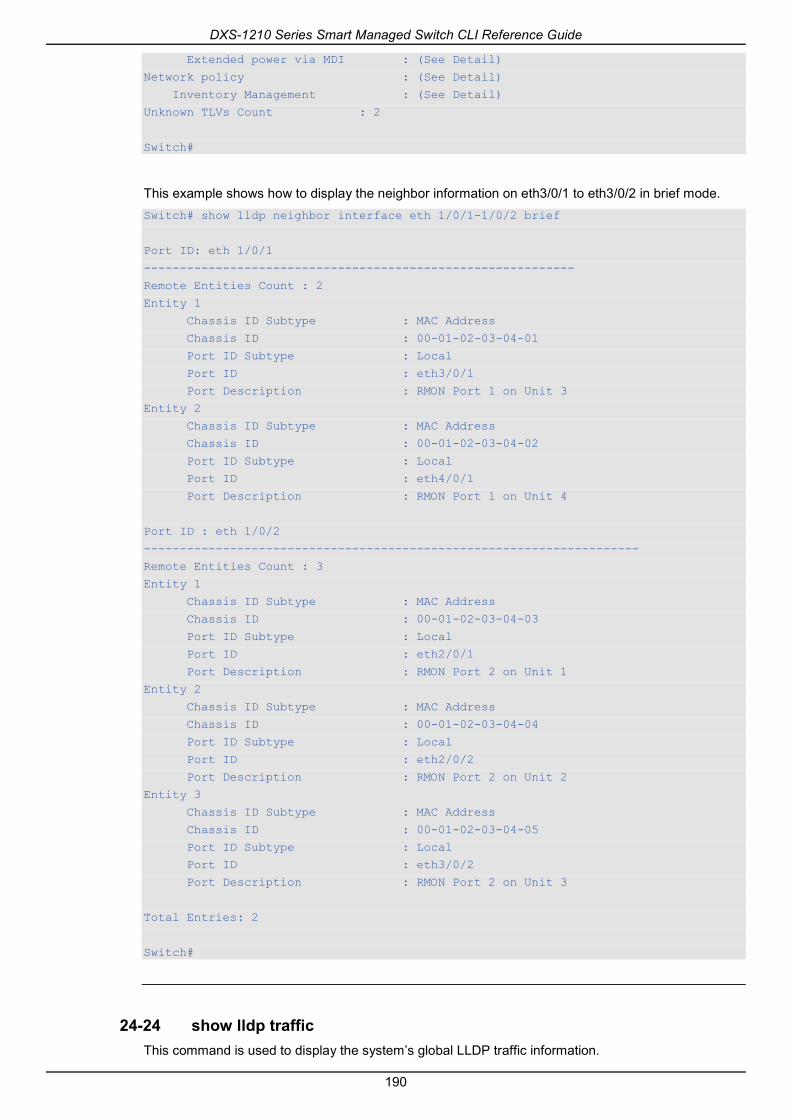
DXS-1210 Series Smart Managed Switch CLI Reference Guide
190
Extended power via MDI : (See Detail)
Network policy : (See Detail)
Inventory Management : (See Detail)
Unknown TLVs Count : 2
Switch#
This example shows how to display the neighbor information on eth3/0/1 to eth3/0/2 in brief mode. Switch# show lldp neighbor interface eth 1/0/1-1/0/2 brief
Port ID: eth 1/0/1
------------------------------------------------------------
Remote Entities Count : 2
Entity 1
Chassis ID Subtype : MAC Address
Chassis ID : 00-01-02-03-04-01
Port ID Subtype : Local
Port ID : eth3/0/1
Port Description : RMON Port 1 on Unit 3
Entity 2
Chassis ID Subtype : MAC Address
Chassis ID : 00-01-02-03-04-02
Port ID Subtype : Local
Port ID : eth4/0/1
Port Description : RMON Port 1 on Unit 4
Port ID : eth 1/0/2
---------------------------------------------------------------------
Remote Entities Count : 3
Entity 1
Chassis ID Subtype : MAC Address
Chassis ID : 00-01-02-03-04-03
Port ID Subtype : Local
Port ID : eth2/0/1
Port Description : RMON Port 2 on Unit 1
Entity 2
Chassis ID Subtype : MAC Address
Chassis ID : 00-01-02-03-04-04
Port ID Subtype : Local
Port ID : eth2/0/2
Port Description : RMON Port 2 on Unit 2
Entity 3
Chassis ID Subtype : MAC Address
Chassis ID : 00-01-02-03-04-05
Port ID Subtype : Local
Port ID : eth3/0/2
Port Description : RMON Port 2 on Unit 3
Total Entries: 2
Switch#
24-24 show lldp traffic This command is used to display the system’s global LLDP traffic information.

DXS-1210 Series Smart Managed Switch CLI Reference Guide
191
show lldp traffic
Parameters None.
Default None.
Command Mode EXEC Mode or Any Configuration Mode.
Command Default Level Level: 1.
Usage Guideline The global LLDP traffic information displays an overview of neighbor detection activities on the Switch.
Example This example shows how to display global LLDP traffic information. Switch#show lldp traffic
Last Change Time : 7958183
Total Inserts : 7
Total Deletes : 0
Total Drops : 0
Total Ageouts : 0
Switch#
Display Parameters
Last Change Time The amount of time since the last update to the remote table in days, hours, minutes, and seconds.
Total Inserts Total number of inserts to the remote data table.
Total Deletes Total number of deletes from the remote data table.
Total Drops Total number of times the complete remote data received was not inserted due to insufficient resources.
Total Ageouts Total number of times a complete remote data entry was deleted because the Time to Live interval expired.
24-25 show lldp traffic interface This command is used to display the each physical interface’s LLDP traffic information.
show lldp traffic interface INTERFACE-ID [, | -]
Parameters
INTERFACE-ID Specifies the interface ID.
, (Optional) Specifies a series of interfaces, or separate a range of

DXS-1210 Series Smart Managed Switch CLI Reference Guide
192
interfaces from a previous range. No spaces before and after the comma.
- (Optional) Specifies a range of interfaces. No spaces before and after the hyphen.
Default None.
Command Mode EXEC Mode or Any Configuration Mode.
Command Default Level Level: 1.
Usage Guideline This command displays LLDP traffic on each physical interface.
Example This example shows how to display statistics information of port 1. Switch#show lldp traffic interface ethernet 1/0/1
Port ID : eth1/0/1
---------------------------------------------
Total Transmits : 0
Total Discards : 0
Total Errors : 0
Total Receives : 0
Total TLV Discards : 0
Total TLV Unknowns : 0
Total Ageouts : 0
Switch#
Display Parameters
Total Transmits The total number of LLDP packets transmitted on the port.
Total Discards The total number of LLDP frames discarded on the port for any reason.
Total Errors The number of invalid LLDP frames received on the port.
Total Receives The total number of LLDP packets received on the port.
Total TLV Discards The number of TLVs discarded.
Total TLV Unknowns The total number of LLDP TLVs received on the port where the type value is in the reserved range, and not recognized.
Total Ageouts The total number of times a complete remote data entry was deleted for the port because the Time to Live interval expired.
24-26 show snmp-server traps lldp This command is used to display LLDP snmp-server traps information.
show snmp-server traps lldp

DXS-1210 Series Smart Managed Switch CLI Reference Guide
193
Parameters None.
Default None.
Command Mode EXEC Mode or Any Configuration Mode.
Command Default Level Level: 1.
Usage Guideline The global LLDP traps information display on the Switch.
Example This example shows how to display global LLDP traffic information. Switch#show snmp-server traps lldp
lldp : Disabled
lldp med : Disabled
Switch#

DXS-1210 Series Smart Managed Switch CLI Reference Guide
194
25. Loopback Detection (LBD) Commands 25-1 loopback-detection (Global)
This command is used to enable the loopback detection function globally. Use the no form of this command to disable the function globally.
loopback-detection [mode {port-based | vlan-based}]
no loopback-detection [mode]
Parameters
mode (Optional) Specifies the detection mode.
port-based Specifies that the loop detection will work in the port-based mode.
vlan-based Specifies that the loop detection will work in the VLAN-based mode.
Default By default, this option is disabled.
By default, the detection mode is port-based.
Command Mode Global Configuration Mode.
Command Default Level Level: 12.
Usage Guideline Generally, port-based loop detection is used in ports that are connected to users, and VLAN-based detection is used in trunk ports when the partner switch does not support the loop detection function.
When doing port-based detection, the LBD enabled port will send untagged port-based LBD packets out from the port to discover the loop. If there is a loop occurrence on the path, then the packet being transmitted will loop back to the same port or to another port located on the same device. When an LBD enabled port detects a loop condition, packet transmitting and receiving is disabled at the port.
When doing VLAN-based detection, the port will periodically send VLAN-based LBD packets for each VLAN that the port has membership of the VLAN is enabled for loop detection. If the port is a tagged member of the detecting VLAN, tagged LBD packets are sent. If the port is an untagged member of the detecting VLAN, untagged LBD packets are sent. If there is a loop occurrence on the VLAN path, then packet transmitting and receiving will be temporarily stopped on the looping VLAN at the port where the loop is detected.
If an LBD disabled port receives an LBD packet and detects that the packet is sent out by the system itself, the sending port will be blocked if the packet is a port-based LBD packet, or the VLAN of the sending port will be blocked if the packet is a VLAN-based LBD packet.
If the port is configured for VLAN-based and if the port is an untagged member of multiple VLANs, then the port will send one untagged LBD packet for each VLAN with the VLAN number specified in the VLAN field of the packet.
There are two ways to recover an error disabled port. The user can use the errdisable recovery cause loopback-detect command to enable the auto-recovery of ports that were disabled by loopback detection. Alternatively, manually recover the port by entering the shutdowncommand followed by the no shutdown command for the port.
The VLAN being blocked on a port can be automatically recovered, if the errdisable recovery cause loopback-detect command is configured. Alternatively, manually recover the operation by entering the shutdown command followed by the no shutdown command for the port.
Example

DXS-1210 Series Smart Managed Switch CLI Reference Guide
195
This example shows how to enable the port-based loopback detection function globally and set the detection mode to port-based. Switch# configure terminal
Switch(config)#loopback-detection
Switch(config)# loopback-detection mode port-based
Switch(config)#
25-2 loopback-detection (Interface) This command is used to enable the loopback detection function for an interface. Use the no form of this command to disable the function for an interface.
loopback-detection
no loopback-detection
Parameters None.
Default By default, this option is disabled.
Command Mode Interface Configuration Mode.
Command Default Level Level: 12.
Usage Guideline Use this command to enable the loopback detection function on an interface. This command is available for port and port-channel interface configuration.
Example This example shows how to enable the loopback detection function on interface eth1/0/1. Switch# configure terminal
Switch(config)#interface eth 1/0/1
Switch(config-if)# loopback-detection
Switch(config-if)#
25-3 loopback-detection interval This command is used to configure the timer interval. Use the no form of this command to revert to the default setting.
loopback-detection interval SECONDS
no loopback-detection interval
Parameters
interval SECONDS Specifies the interval in seconds at which CPT packets are transmitted. The valid range is from 1 to 32767.

DXS-1210 Series Smart Managed Switch CLI Reference Guide
196
Default By default, this value is 10 seconds.
Command Mode Global Configuration Mode.
Command Default Level Level: 12.
Usage Guideline Use this command to configure the interval at which LBD packets are sent to discover the loop occurrence.
Example This example shows how to configure the time interval to 20 seconds. Switch# configure terminal
Switch(config)#loopback-detection interval 20
Switch(config)#
25-4 loopback-detection vlan This command is used to configure the VLANs to be enabled for loop detection. Use the no form of this command to revert to the default setting.
loopback-detection vlan VLAN-LIST
no loopback-detection vlan VLAN-LIST
Parameters
VLAN-LIST Specifies the VLAN identification number, numbers, or range of numbers to be matched. Enter one or more VLAN values separated by commas or hyphens for a range list.
Default By default, this option is enabled for all VLANs.
Command Mode Global Configuration Mode.
Command Default Level Level: 12.
Usage Guideline Use this command to configure the list of VLANs that are enabled for loop detection. The command setting takes effect when the port’s loop detection mode is operated in the VLAN-based mode.
If the VLAN ID list is empty, LBD Control packets are sent out for all VLANs that the port is a member of. LBD Control packets will be sent out for the VLAN that the member port within the specified VLAN list.
The VLAN list can be incremented by issuing this command multiple times.
Example This example shows how to enable VLANs 100 to 200 for loop detection.

DXS-1210 Series Smart Managed Switch CLI Reference Guide
197
Switch# configure terminal
Switch(config)#loopback-detection vlan 100-200
Switch(config)#
25-5 show loopback-detection This command is used to display the current loopback detection control settings.
show loopback-detection [interface INTERFACE-ID [, | -]]
Parameters
interface INTERFACE-ID (Optional) Specifies the interface’s ID to be displayed.
, (Optional)Specifies a series of interfaces, or separate a range of interfaces from a previous range. No spaces are allowed before and after the comma.
- (Optional)Specifies a range of interfaces. No spaces are allowed before and after the hyphen.
Default None.
Command Mode EXEC Mode or Any Configuration Mode.
Command Default Level Level: 1.
Usage Guideline Use this command to display the loopback detection setting and status.
Example This example shows how to displays the current loopback detection settings and status.

DXS-1210 Series Smart Managed Switch CLI Reference Guide
198
Switch# show loopback-detection
Loop Detection : Enabled
Detection Mode : vlan-based
LBD enabled VLAN : all VLANs
Interval : 20 seconds
Action : Shut-down
Interface Loopback Detection State Result Time Left(sec)
------------- ------------------------ -------------- -------------
eth1/0/3 Disabled Normal 0
eth1/0/4 Disabled Normal 0
eth1/0/5 Disabled Normal 0
eth1/0/6 Disabled Normal 0
eth1/0/7 Disabled Normal 0
eth1/0/8 Disabled Normal 0
eth1/0/9 Disabled Normal 0
eth1/0/10 Disabled Normal 0
eth1/0/11 Enabled Loop on VLAN 1 infinite
eth1/0/12 Enabled Loop on VLAN 1 infinite
Port-Channel1 Disabled Normal 0
Switch#
This example shows how to displays the loopback detection status for port 1/0/1. Switch# show loopback-detection interface eth 1/0/1
Interface Loopback Detection State Result Time Left(sec)
------------- ------------------------ -------------- -------------
eth1/0/11 Enabled Loop on VLAN 1 infinite
Switch#
This example shows how to displays the loopback detection status for port-channel 2. Switch# show loopback-detection interface port-channel 2
Interface Loopback Detection State Result Time Left(sec)
------------- ------------------------ -------------- -------------
Port-Channel1 Disabled Normal 0
Switch#
Display Parameters
Interface Indicates the port that has loopback detection enabled.
Result Indicates whether a loop is detected.
Time Left The remaining time before being auto-recovered.
25-6 snmp-server enable traps loopback-detection This command is used toenable the sending SNMP notifications of loopback detection. Use the no form of this command to revert to the default setting.

DXS-1210 Series Smart Managed Switch CLI Reference Guide
199
snmp-server enable traps loopback-detection
no snmp-server enable traps loopback-detection
Parameters None.
Default By default, this option is disabled.
Command Mode Global Configuration Mode.
Command Default Level Level: 12.
Usage Guideline Use this command to enable or disable the sending SNMP notifications of loopback detection.
Example This example shows how to enable the sending SNMP notifications of loopback detection. Switch# configure terminal
Switch(config)# snmp-server enable traps loopback-detection.
Switch(config)#
25-7 show snmp-server traps This command is used toenable the sending SNMP notifications of loopback detection. Use the no form of this command to revert to the default setting.
show snmp-server traps loopback-detection
Parameters None.
Default None.
Command Mode EXEC Mode
Any Configuration Mode.
Command Default Level Level: 1.
Usage Guideline Use this command to display loopback-detection SNMP trap state.
Example This example shows how to enable the sending SNMP notifications of loopback detection.

DXS-1210 Series Smart Managed Switch CLI Reference Guide
200
Switch# show snmp-server traps loopback-detection
Loopback Detection Trap State: disable
Switch#
25-8 loopback-detection action This command is used to set the loop action of loopback detection. Use the no form of this command to revert to the default setting.
loopback-detection action {shutdown | none}
no loopback-detection action
Parameters
shutdown Loop action to shutdown port
none Loop action none
Default None.
Command Mode Global Configuration Mode.
Command Default Level Level: 12.
Usage Guideline Use this command to configure the loop action.
Example This example shows how to set the loop action of loopback detection. Switch(config)# loopback-detection action shutdown
Switch(config)#
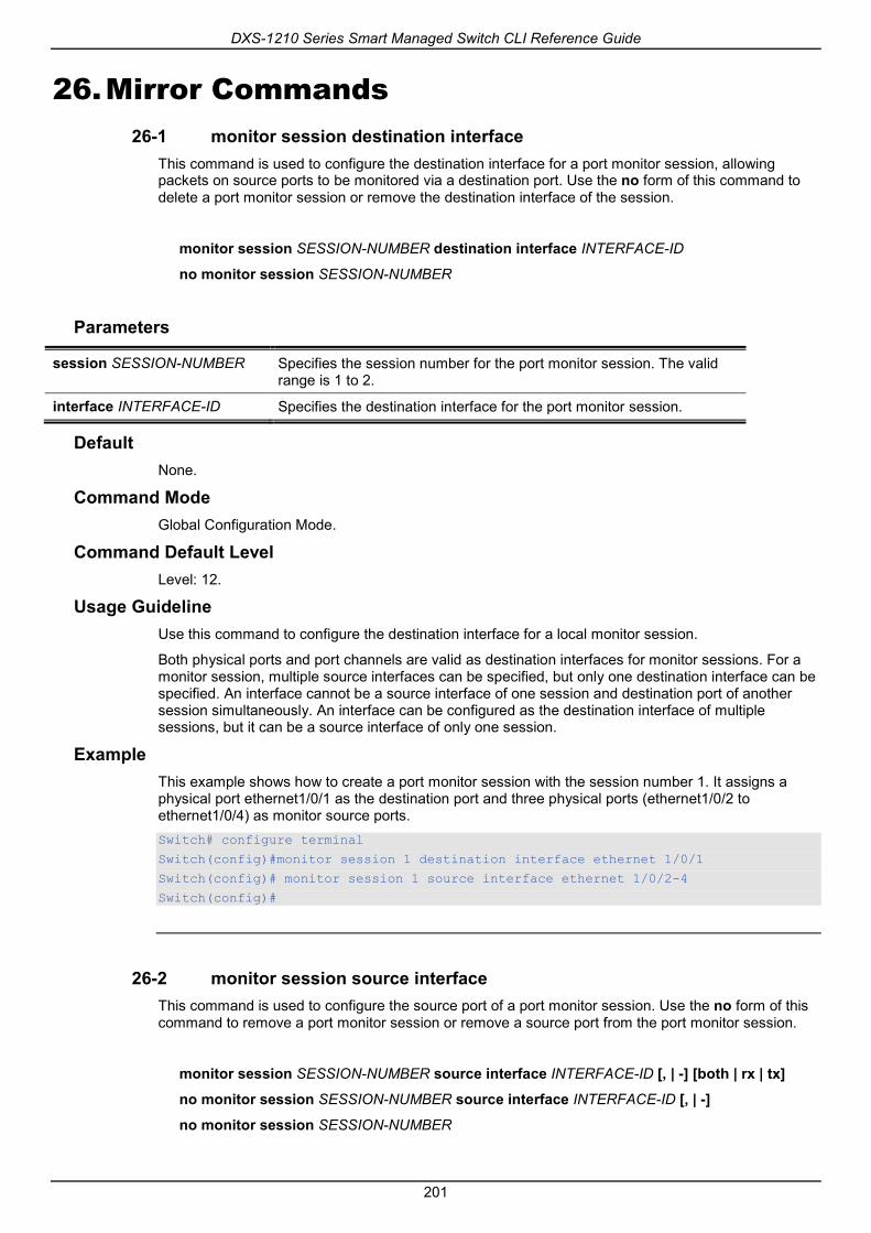
DXS-1210 Series Smart Managed Switch CLI Reference Guide
201
26. Mirror Commands 26-1 monitor session destination interface
This command is used to configure the destination interface for a port monitor session, allowing packets on source ports to be monitored via a destination port. Use the no form of this command to delete a port monitor session or remove the destination interface of the session.
monitor session SESSION-NUMBER destination interface INTERFACE-ID
no monitor session SESSION-NUMBER
Parameters
session SESSION-NUMBER Specifies the session number for the port monitor session. The valid range is 1 to 2.
interface INTERFACE-ID Specifies the destination interface for the port monitor session.
Default None.
Command Mode Global Configuration Mode.
Command Default Level Level: 12.
Usage Guideline Use this command to configure the destination interface for a local monitor session.
Both physical ports and port channels are valid as destination interfaces for monitor sessions. For a monitor session, multiple source interfaces can be specified, but only one destination interface can be specified. An interface cannot be a source interface of one session and destination port of another session simultaneously. An interface can be configured as the destination interface of multiple sessions, but it can be a source interface of only one session.
Example This example shows how to create a port monitor session with the session number 1. It assigns a physical port ethernet1/0/1 as the destination port and three physical ports (ethernet1/0/2 to ethernet1/0/4) as monitor source ports. Switch# configure terminal
Switch(config)#monitor session 1 destination interface ethernet 1/0/1
Switch(config)# monitor session 1 source interface ethernet 1/0/2-4
Switch(config)#
26-2 monitor session source interface This command is used to configure the source port of a port monitor session. Use the no form of this command to remove a port monitor session or remove a source port from the port monitor session.
monitor session SESSION-NUMBER source interface INTERFACE-ID [, | -] [both | rx | tx]
no monitor session SESSION-NUMBER source interface INTERFACE-ID [, | -]
no monitor session SESSION-NUMBER

DXS-1210 Series Smart Managed Switch CLI Reference Guide
202
Parameters
session SESSION-NUMBER Specifies the session number for the port monitor session. The valid range is 1 to 4.
interface INTERFACE-ID Specifies the source interface for a port monitor session.
, (Optional) Specifies the number of interfaces, or separate a range of interfaces from a previous range. No spaces before and after the comma.
- (Optional) Specifies a range of interfaces. No spaces before and after the hyphen.
both (Optional) Specifies to monitor the packets transmitted and received on the port.
rx (Optional) Specifies to monitor the packets received on the port.
tx (Optional) Specifies to monitor the packets transmitted on the portwithout forwarding, which means regardless of the port’s STG status.
Default None.
Command Mode Global Configuration Mode.
Command Default Level Level: 12.
Usage Guideline Both physical ports and port channels are valid as source interfaces of monitor sessions.
For a monitor session, multiple source interfaces can be specified, but only one destination interface can be specified. An interface cannot be a source interface of one session and destination port of another session simultaneously. An interface can be configured as destination interface of multiple sessions, but it can be a source interface of only one session.
If the direction is not specified, both TX (transmitted) and RX (received) traffic are monitored. Once TX forwarding has been specified, it cannot be changed back to TX only.
Example This example shows how to create a port monitor session with session number 1. It assigns a physical port ethernet1/0/1 as a destination port and three physical ports (ethernet1/0/2 to ethernet1/0/4) as monitor source ports. Switch# configure terminal
Switch(config)#monitor session 1 destination interface ethernet 1/0/1
Switch(config)# monitor session 1 source interface ethernet 1/0/2-4
Switch(config)#
26-3 show monitor session This command is used to display all or a specific port mirroring session.
show monitor session [SESSION-NUMBER]
Parameters
SESSION-NUMBER (Optional) Specifies the session number which you want to display.
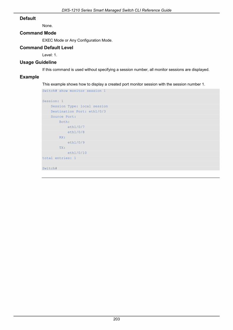
DXS-1210 Series Smart Managed Switch CLI Reference Guide
203
Default None.
Command Mode EXEC Mode or Any Configuration Mode.
Command Default Level Level: 1.
Usage Guideline If this command is used without specifying a session number, all monitor sessions are displayed.
Example This example shows how to display a created port monitor session with the session number 1. Switch# show monitor session 1
Session: 1
Session Type: local session
Destination Port: eth1/0/3
Source Port:
Both:
eth1/0/7
eth1/0/8
RX:
eth1/0/9
TX:
eth1/0/10
total entries: 1
Switch#

DXS-1210 Series Smart Managed Switch CLI Reference Guide
204
27. MLD Snooping Commands 27-1 clear ipv6 mld snooping statistics
This command is used to clear the statistic counter of the Switch.
clear ipv6 mld snooping statistics {all | vlan VLAN-ID}
Parameters
all Specifies to clear IPv6 MLD snooping statistics for all VLANs and all ports.
vlan VLAN-ID Specifies the VLAN used. If no VLAN is specified, statistics for all VLANs are cleared.
Default None.
Command Mode Privilege EXEC Mode.
Command Default Level Level: 12.
Usage Guideline This command is used to clear the statistic counter of the Switch.
Example This example shows how to clear all MLD snooping statistics. Switch# clear ipv6 mld snooping statistics all
Switch#
27-2 ipv6 mld snooping This command is used to enable or disable MLD snooping.
ipv6 mld snooping
no ipv6 mld snooping
Parameters None.
Default MLD snooping is disabled on all VLAN interfaces.
The MLD snooping global state is disabled by default.
Command Mode Interface Configuration Mode.
Global Configuration Mode.
Command Default Level

DXS-1210 Series Smart Managed Switch CLI Reference Guide
205
Level: 12.
Usage Guideline For a VLAN to operate with MLD snooping, both the global state and per interface state must be enabled. On a VLAN, the setting of IGMP snooping and MLD snooping are independent. That is, IGMP snooping and MLD snooping can be simultaneously enabled on the same VLAN.
Example This example shows how to disable MLD snooping globally. Switch# configure terminal
Switch(config)#no ipv6 mld snooping
Switch(config)#
This example shows how to enable MLD snooping globally. Switch# configure terminal
Switch(config)# ipv6 mld snooping
Switch(config)#
This example shows how to enable MLD snooping on VLAN1. Switch# configure terminal
Switch(config)# vlan 1
Switch(config-vlan)# ipv6 mld snooping
Switch(config-vlan)#
27-3 ipv6 mld snooping fast-leave This command is used to configure MLD snooping fast-leave on the interface. Use the no form of this command to disable the fast-leave option on the specified interface.
ipv6 mld snooping fast-leave
no ipv6 mld snooping fast-leave
Parameters None.
Default By default, this option is disabled.
Command Mode Interface Configuration Mode.
Command Default Level Level: 12.
Usage Guideline The command is only available for VLAN interface configuration. The ipv6 mld snooping fast-leave command allows MLD membership to beimmediately removed from a port when receiving the leave message without using the group specific or group-source specific query mechanism.
Example This example shows how to enable MLD snooping fast-leave on VLAN 1.

DXS-1210 Series Smart Managed Switch CLI Reference Guide
206
Switch# configure terminal
Switch(config)#vlan 1
Switch(config-vlan)# ipv6 mld snooping fast-leave
Switch(config-vlan)#
27-4 ipv6 mld snooping last-listener-query-interval This command is used to configure the interval at which the MLD snooping querier sends MLD group-specific or group-source-specific (channel) query messages. Use the no form of this command to revert to the default setting.
ipv6 mld snooping last-listener-query-interval SECONDS
no ipv6 mld snooping last-listener-query-interval
Parameters
SECONDS Specifies the maximum amount of time between group-specific query messages, including those sent in response to leave-group messages. The range of this value is 1 to 25.
Default By default, this value is 1 second.
Command Mode Interface Configuration Mode.
Command Default Level Level: 12.
Usage Guideline The command is only available for VLAN interface configuration. On receiving an MLD done message, the MLD snooping querier will assume that there are no local members on the interface if there are no reports received after the response time. Users can lower this interval to reduce the amount of time it takes a switch to detect the loss of the last member of a group.
Example This example shows how to configure the last-listener query interval time to be 3 seconds on VLAN 1000. Switch# configure terminal
Switch(config)#vlan 1000
Switch(config-vlan)# ipv6 mld snooping last-listener-query-interval 3
Switch(config-vlan)#
27-5 ipv6 mld snooping mrouter This command is used to configure the specified interface(s) as the router ports or forbidden to be IPv6 multicast router ports on the VLAN interface on the Switch. Use the no form of this command to remove the interface(s) from router ports or forbidden IPv6 multicast router ports.
ipv6 mld snooping mrouter {interface INTERFACE-ID [,|-] | forbidden interface INTERFACE-ID [,|-]}
no ipv6 mld snooping mrouter {interface INTERFACE-ID [,|-] | forbidden interface INTERFACE-ID [,|-]}

DXS-1210 Series Smart Managed Switch CLI Reference Guide
207
Parameters
interface Specifies a range of interfaces as being connected to multicast-enabled routers.
forbidden interface Specifies a range of interfaces as being not connected to multicast-enabled routers.
INTERFACE-ID Specifies an interface or an interface list. No space is allowed before and after the comma. The interface can be a physical interface or a port-channel.
Default No IPv6 MLD snooping multicast router port is configured.
Auto-learning is enabled.
Command Mode Interface Configuration Mode.
Command Default Level Level: 12.
Usage Guideline The command is only available for VLAN interface configuration. To specify a multicast router port, the valid interface can be a physical port or a port-channel. The specified multicast router port must be member port of the configured VLAN.
The multicast router port can be either dynamically learned or statically configured into an MLD snooping entity. With the dynamic learning, the MLD snooping entity will listen to MLD and PIMv6 packet to identify whether the partner device is a router.
Example This example shows how to configure eth1/0/1 as an MLD snooping multicast router port and eth1/0/2 as an MLD snooping forbidden multicast router port on VLAN 1. Switch# configure terminal
Switch(config)#vlan 1
Switch(config-vlan)# ipv6 mld snooping mrouter interface eth 1/0/1
Switch(config-vlan)# ipv6 mld snooping mrouter forbidden interface eth 1/0/2
Switch(config-vlan)#
27-6 ipv6 mld snooping querier This command is used to enable the MLD snooping querier on the Switch. Use the no form of this command to disable the MLD snooping querier function.
ipv6 mld snooping querier
no ipv6 mld snooping querier
Parameters None.
Default By default, this option is disabled.
Command Mode Interface Configuration Mode.
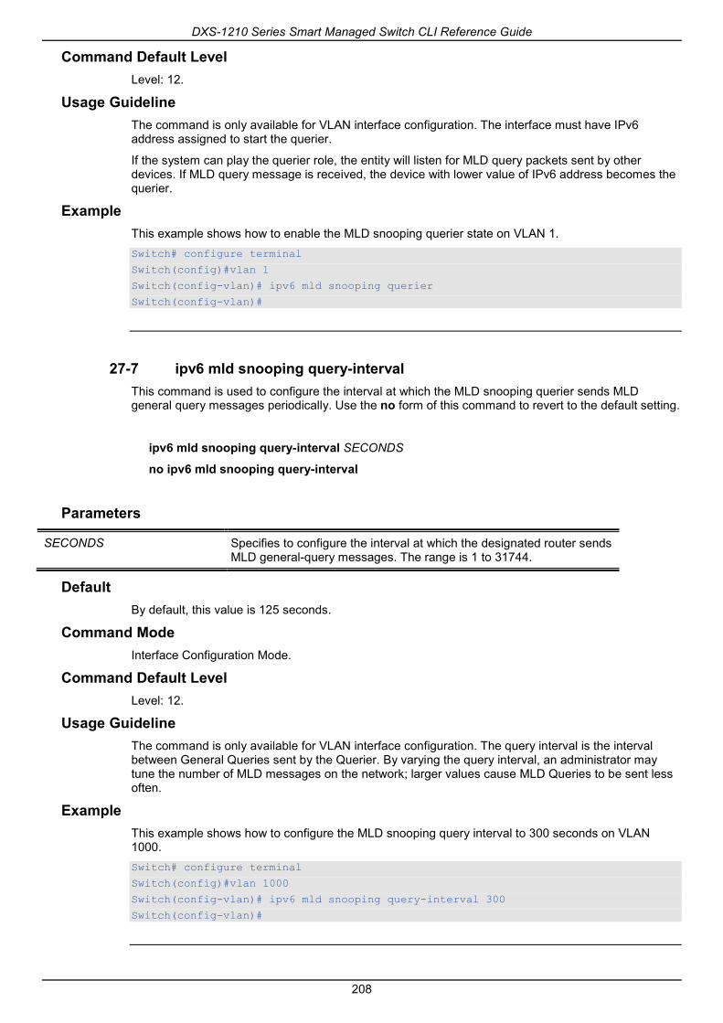
DXS-1210 Series Smart Managed Switch CLI Reference Guide
208
Command Default Level Level: 12.
Usage Guideline The command is only available for VLAN interface configuration. The interface must have IPv6 address assigned to start the querier.
If the system can play the querier role, the entity will listen for MLD query packets sent by other devices. If MLD query message is received, the device with lower value of IPv6 address becomes the querier.
Example This example shows how to enable the MLD snooping querier state on VLAN 1. Switch# configure terminal
Switch(config)#vlan 1
Switch(config-vlan)# ipv6 mld snooping querier
Switch(config-vlan)#
27-7 ipv6 mld snooping query-interval This command is used to configure the interval at which the MLD snooping querier sends MLD general query messages periodically. Use the no form of this command to revert to the default setting.
ipv6 mld snooping query-interval SECONDS
no ipv6 mld snooping query-interval
Parameters
SECONDS Specifies to configure the interval at which the designated router sends MLD general-query messages. The range is 1 to 31744.
Default By default, this value is 125 seconds.
Command Mode Interface Configuration Mode.
Command Default Level Level: 12.
Usage Guideline The command is only available for VLAN interface configuration. The query interval is the interval between General Queries sent by the Querier. By varying the query interval, an administrator may tune the number of MLD messages on the network; larger values cause MLD Queries to be sent less often.
Example This example shows how to configure the MLD snooping query interval to 300 seconds on VLAN 1000. Switch# configure terminal
Switch(config)#vlan 1000
Switch(config-vlan)# ipv6 mld snooping query-interval 300
Switch(config-vlan)#
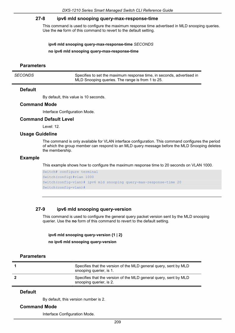
DXS-1210 Series Smart Managed Switch CLI Reference Guide
209
27-8 ipv6 mld snooping query-max-response-time This command is used to configure the maximum response time advertised in MLD snooping queries. Use the no form of this command to revert to the default setting.
ipv6 mld snooping query-max-response-time SECONDS
no ipv6 mld snooping query-max-response-time
Parameters
SECONDS Specifies to set the maximum response time, in seconds, advertised in MLD Snooping queries. The range is from 1 to 25.
Default By default, this value is 10 seconds.
Command Mode Interface Configuration Mode.
Command Default Level Level: 12.
Usage Guideline The command is only available for VLAN interface configuration. This command configures the period of which the group member can respond to an MLD query message before the MLD Snooping deletes the membership.
Example This example shows how to configure the maximum response time to 20 seconds on VLAN 1000. Switch# configure terminal
Switch(config)#vlan 1000
Switch(config-vlan)# ipv6 mld snooping query-max-response-time 20
Switch(config-vlan)#
27-9 ipv6 mld snooping query-version This command is used to configure the general query packet version sent by the MLD snooping querier. Use the no form of this command to revert to the default setting.
ipv6 mld snooping query-version {1 | 2}
no ipv6 mld snooping query-version
Parameters
1 Specifies that the version of the MLD general query, sent by MLD snooping querier, is 1.
2 Specifies that the version of the MLD general query, sent by MLD snooping querier, is 2.
Default By default, this version number is 2.
Command Mode Interface Configuration Mode.

DXS-1210 Series Smart Managed Switch CLI Reference Guide
210
Command Default Level Level: 12.
Usage Guideline The command is only available for VLAN interface configuration.
Example This example shows how to configure the query version to be 1 on VLAN 1000. Switch# configure terminal
Switch(config)#vlan 1000
Switch(config-vlan)# ipv6 mld snooping query-version 1
Switch(config-vlan)#
27-10 ipv6 mld snooping robustness-variable This command is used to set the robustness variable used in MLD snooping. Use the no form of this command to revert to the default value.
ipv6 mld snooping robustness-variable VALUE
no ipv6 mld snooping robustness-variable
Parameters
VALUE Specifies the robustness variable. The range is from 1 to 7.
Default By default, this value is 2.
Command Mode Interface Configuration Mode.
Command Default Level Level: 12.
Usage Guideline The command is only available for VLAN interface configuration.
The robustness variable provides fine-tuning to allow for expected packet loss on an interface. The value of the robustness variable is used in calculating the following MLD message intervals:
• Group member interval - Amount of time that must pass before a multicast router decides there are no more members of a group on a network. This interval is calculated as follows: (robustness variable x query interval) + (1 x query response interval).
• Other querier present interval - Amount of time that must pass before a multicast router decides that there is no longer another multicast router that is the querier. This interval is calculated as follows: (robustness variable x query interval) + (0.5 x query response interval).
• Last listener query count - The number of group-specific queries sent before the router assumes there are no local listeners of a group. The default number is the value of the robustness variable.
User can increase this value if a subnet is expected to be loose.
Example This example shows how to configure the robustness variable to be 3 on interface VLAN 1000.

DXS-1210 Series Smart Managed Switch CLI Reference Guide
211
Switch# configure terminal
Switch(config)#vlan 1000
Switch(config-vlan)# ipv6 mld snooping robustness-variable 3
Switch(config-vlan)#
27-11 ipv6 mld snooping static-group This command is used to configure an MLD snooping static group. Use the no form of this command to delete a static group.
ipv6 mld snooping static-group IPV6-ADDRESS interface INTERFACE-ID [,|-]
no ipv6 mld snooping static-group IPV6-ADDRESS [interface INTERFACE-ID [,|-]]
Parameters
IPV6-ADDRESS Specifies an IPv6 multicast group address.
interface INTERFACE-ID [,|-] Specifies an interface or an interface list. No space is allowed before and after the comma. The interface can be a physical interface or a port-channel.
Default No static-group is configured.
Command Mode Interface Configuration Mode.
Command Default Level Level: 12.
Usage Guideline The command is only available for VLAN interface configuration. This command applies to MLD snooping on a VLAN interface to statically add group membership entries.
The ipv6 mld snooping static-group command allows the user to create an MLD snooping static group in case that the attached host does not support MLD protocol.
Example This example shows how to statically add group records for MLD snooping on VLAN 1. Switch# configure terminal
Switch(config)#vlan 1
Switch(config-vlan)# ipv6 mld snooping static-group FF02::12:03 interface eth 1/0/5
Switch(config-vlan)#
27-12 show ipv6 mld snooping This command is used to display MLD snooping information on the Switch.
show ipv6 mld snooping [vlan VLAN-ID]
Parameters
vlan VLAN-ID (Optional) Specifies the VLAN to be displayed.

DXS-1210 Series Smart Managed Switch CLI Reference Guide
212
Default None.
Command Mode EXEC Mode or Any Configuration Mode.
Command Default Level Level: 1.
Usage Guideline Use this command to display MLD snooping information for all VLANs on which MLD snooping are enabled by not specifying specific VLAN.
Example This example shows how to display MLD snooping configurations. Switch# show ipv6 mld snooping
MLD snooping global state: Enabled
VLAN #1 configuration
MLD snooping state : Enabled
Fast leave : Enabled (host-based)
Querier state : Enabled (Non-active)
Query version : v2
Query interval : 125 seconds
Max response time : 10 seconds
Robustness value : 2
Last listener query interval : 1 seconds
Total Entries: 1
Switch#
27-13 show ipv6 mld snooping groups This command is used to display MLD snooping group-related information learned on the Switch.
show ipv6 mld snooping groups [IPV6-ADDRESS | vlan VLAN-ID]
Parameters
IPV6-ADDRESS (Optional) Specifies the group IPv6 address. If no IPv6 address is specified, all MLD group information will be displayed.
vlan VLAN-ID (Optional) Specifies the VLAN interface. If no interface is specified, MLD group information about all interfaces will be displayed.
Default None.
Command Mode EXEC Mode or Any Configuration Mode.
Command Default Level Level: 1.

DXS-1210 Series Smart Managed Switch CLI Reference Guide
213
Usage Guideline Use this command to display MLD group information by command.
Example This example shows how to display MLD snooping group information. Switch# show ipv6 mld snooping groups
MLD Snooping Connected Group Membership:
VLAN ID Group address Source address Exp(sec) Interface
------- ------------------- ------------------- -------- ---------
1 FF1E:: * 258 2/0/7
1 FF1E::3 * 258 2/0/7
1 FF1E::4 3620:110:1::3a2b 258 2/0/7
Total Entries: 3
Switch#
27-14 show ipv6 mld snooping mrouter This command is used to display MLD snooping multicast router port information automatically learned or manually configured on the Switch.
show ipv6 mld snooping mrouter [vlan VLAN-ID]
Parameters
vlan VLAN-ID (Optional) Specifies the VLAN. If no VLAN is specified, MLD snooping Multicast Router Information on all VLANs will be displayed.
Default None.
Command Mode EXEC Mode or Any Configuration Mode.
Command Default Level Level: 1.
Usage Guideline Use this command to display dynamically learned or manually configured multicast router interfaces.
Example This example shows how to display MLD snooping multicast router information.

DXS-1210 Series Smart Managed Switch CLI Reference Guide
214
Switch# show ipv6 mld snooping mrouter
VLAN Ports
----- -----------------------------
4094 1/0/12 (forbidden)
Total Entries: 3
Switch#
27-15 show ipv6 mld snooping static-group This command is used to display MLD snooping static group information on the Switch.
show ipv6 mld snooping static-group [GROUP-ADDRESS | vlan VLAN-ID]
Parameters
GROUP-ADDRESS Specifies the group IPv6 address to be displayed.
vlan VLAN-ID Specifies the VLAN ID to be displayed.
Default None.
Command Mode EXEC Mode or Any Configuration Mode.
Command Default Level Level: 1.
Usage Guideline This command displays the MLD snooping static group information.
Example This example shows how to display MLD snooping static group information . Switch#show ipv6 mld snooping static-group
VLAN ID Group address Interface
------- --------------- ------------------------
1 FF1E::1 1/0/1,1/0/5
Total Entries: 1
Switch#
27-16 show ipv6 mld snooping statistics This command is used to display MLD snooping statistics information on the Switch.
show ipv6 mld snooping statistics vlan [VLAN-ID]

DXS-1210 Series Smart Managed Switch CLI Reference Guide
215
Parameters
vlan VLAN-ID Specifies the VLAN of which to display the VLAN statistics.
Default None.
Command Mode EXEC Mode or Any Configuration Mode.
Command Default Level Level: 1.
Usage Guideline This command displays the MLD snooping related statistics information.
Example This example shows how to display MLD snooping statistics information. Switch# show ipv6 mld snooping statistics interface
Interface eth4/0/1
Rx: V1Report 1, v2Report 2, Query 1, v1Done 2
Tx: v1Report 1, v2Report 2, Query 1, v1Done 2
Interface eth4/0/3
Rx: V1Report 0, v2Report 0, Query 0, v1Done 0
Tx: v1Report 0, v2Report 0, Query 0, v1Done 0
Interface eth4/0/4
Rx: V1Report 3, v2Report 0, Query 3, v1Done 0
Tx: v1Report 2, v2Report 2, Query 1, v1Done 2
Total Entries: 3
Switch# show ipv6 mld snooping statistics vlan
VLAN1 Statistics:
Rx: v1Report 0, v2Report 58, Query 0, v1Done 0
Tx: v1Report 0, v2Report 0, Query 0, v1Done 0
Total Entries: 1
Switch#

DXS-1210 Series Smart Managed Switch CLI Reference Guide
216
28. Multiple Spanning Tree Protocol (MSTP) Commands
28-1 instance This command is used to map a VLAN or a set of VLANs to an MST instance. Use the no instance without VLANs specified to remove instances. Use the no instance with VLAN specified to return the VLANs to the default instance (CIST).
instance INSTANCE-ID vlans VLANDID [, | -]
no instance INSTANCE-ID [vlans VLANDID [, | -]]
Parameters
INSTANCE-ID Specifies the MSTP instance identifier to which the specified VLANs are mapped. This value must be between 1 and 4094.
vlans VLANDID Specifies the VLANs to be mapped to or removed from the specified instance.This value must be between 1 and 4094.
, (Optional)Specifies a series of VLAN, or separate a range of interfaces from a previous range. No space is allowed before and after the comma.
- (Optional)Specifies a range of VLAN. No space is allowed before and after the hyphen.
Default None.
Command Mode MST Configuration Mode.
Command Default Level Level: 12.
Usage Guideline Any unmapped VLAN is mapped to the CIST instance. When mapping the VLANs to an instance, if the instance doesn’t exist, this instance will be created automatically. If all VLANs of an instance are removed, this instance will be destroyed automatically. In another way, users can remove the instance manually by using the no instance command without VLANs specified.
Example This example shows how to map a range of VLANs to instance 2. Switch# configure terminal
Switch(config)#spanning-tree mst configuration
Switch(config-mst)# instance 2 vlans 1-100
Switch(config-mst)#
28-2 name This command is used to configure the name of an MST region. Use the no form of this command to revert to the default setting.
name NAME

DXS-1210 Series Smart Managed Switch CLI Reference Guide
217
no name NAME
Parameters
NAME Specifies the name given for a specified MST region. The name string has a maximum length of 32 characters and the type is a general string which allows spaces.
Default The default name is the Switch’s MAC address.
Command Mode MST Configuration Mode.
Command Default Level Level: 12.
Usage Guideline Two or more switches with the same VLAN mapping and configuration version number are considered to be in different MST regions if the region names are different.
Example This example shows how to configure the MSTP configuration name to “MName”. Switch# configure terminal
Switch(config)#spanning-tree mst configuration
Switch(config-mst)# name MName
Switch(config-mst)#
28-3 revision This command is used to configure the revision number for the MST configuration. Use the no form of this command to revert to the default setting.
revision VERSION
no revision
Parameters
VERSION Specifies the revision number for the MST configuration. The range is from 0 to 65535.
Default By default, this value is 0.
Command Mode MST Configuration Mode.
Command Default Level Level: 12.
Usage Guideline Two Ethernet switches that have the same configuration but different revision numbers are considered to be part of two different regions.
Example
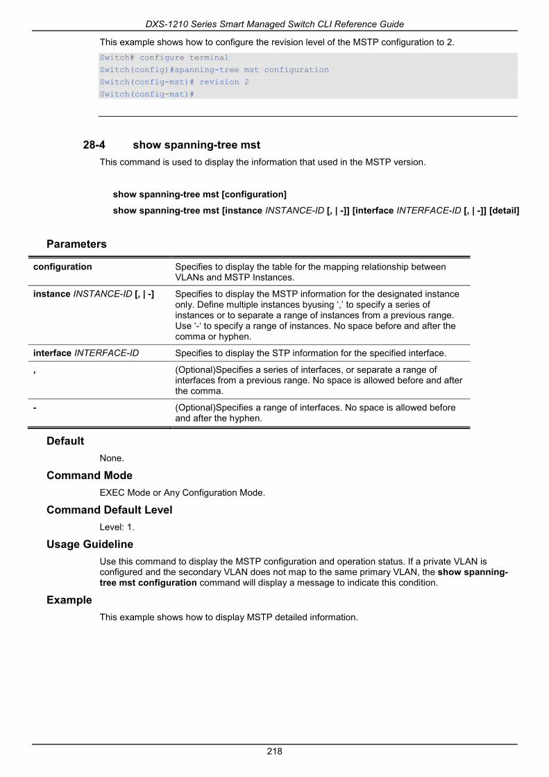
DXS-1210 Series Smart Managed Switch CLI Reference Guide
218
This example shows how to configure the revision level of the MSTP configuration to 2. Switch# configure terminal
Switch(config)#spanning-tree mst configuration
Switch(config-mst)# revision 2
Switch(config-mst)#
28-4 show spanning-tree mst This command is used to display the information that used in the MSTP version.
show spanning-tree mst [configuration]
show spanning-tree mst [instance INSTANCE-ID [, | -]] [interface INTERFACE-ID [, | -]] [detail]
Parameters
configuration Specifies to display the table for the mapping relationship between VLANs and MSTP Instances.
instance INSTANCE-ID [, | -] Specifies to display the MSTP information for the designated instance only. Define multiple instances byusing ‘,’ to specify a series of instances or to separate a range of instances from a previous range. Use ‘-‘ to specify a range of instances. No space before and after the comma or hyphen.
interface INTERFACE-ID Specifies to display the STP information for the specified interface.
, (Optional)Specifies a series of interfaces, or separate a range of interfaces from a previous range. No space is allowed before and after the comma.
- (Optional)Specifies a range of interfaces. No space is allowed before and after the hyphen.
Default None.
Command Mode EXEC Mode or Any Configuration Mode.
Command Default Level Level: 1.
Usage Guideline Use this command to display the MSTP configuration and operation status. If a private VLAN is configured and the secondary VLAN does not map to the same primary VLAN, the show spanning-tree mst configuration command will display a message to indicate this condition.
Example This example shows how to display MSTP detailed information.

DXS-1210 Series Smart Managed Switch CLI Reference Guide
219
Switch#show spanning-tree mst detail
Spanning tree: Disabled,protocol: RSTP
Number of MST instances: 1
>>>>MST00 vlans mapped : 1-4094
Bridge Address: 00-01-02-03-04-00, Priority: 32768 (32768 sysid 0)
Designated Root Address: 00-00-00-00-00-00, Priority: 0 (0 sysid 0)
Regional Root Bridge Address: 00-00-00-00-00-00, Priority: 0 (0 sysid 0)
Designated Bridge Address: 00-00-00-00-00-00, Priority: 0 (0 sysid 0)
eth1/0/1
Port state: forwarding
Port role: nonStp
Port info : port ID 128.1, priority: 128, cost: 200000
Designated root address: 00-00-00-00-00-00, priority: 0
Regional Root address: 00-00-00-00-00-00, priority: 0
Designated bridge address: 00-00-00-00-00-00, priority: 0, port id: 0.0
Switch#
This example shows how to display MSTP detailed information for interface eth1/0/1. Switch#show spanning-tree mst interface eth 1/0/1 detail
eth1/0/1
Configured link type: auto, operation status: point-to-point
Configured fast-forwarding: auto, operation status: non-edge
>>>>MST instance: 00, vlans mapped : 1-4094
Port state: forwarding
Port role: nonStp
Port info : port ID 128.1, priority: 128, cost: 200000
Designated root address: 00-00-00-00-00-00, priority: 0
Regional Root address: 00-00-00-00-00-00, priority: 0
Designated bridge address: 00-00-00-00-00-00, priority: 0, port id: 0.0
Switch#
This example shows how to display MSTP summary information.

DXS-1210 Series Smart Managed Switch CLI Reference Guide
220
Switch#show spanning-tree mst
Spanning tree: Disabled,protocol: RSTP
Number of MST instances: 1
>>>>MST00 vlans mapped : 1-4094
Bridge Address: 00-01-02-03-04-00, Priority: 32768 (32768 sysid 0)
Designated Root Address: 00-00-00-00-00-00, Priority: 0 (0 sysid 0)
Regional Root Bridge Address: 00-00-00-00-00-00, Priority: 0 (0 sysid 0)
Designated Bridge Address: 00-00-00-00-00-00, Priority: 0 (0 sysid 0)
Priority
Interface Role State Cost .Port#
--------- ---- ----- ---- -------
eth1/0/1 nonStp forwarding 200000 128.1
Switch#
This example shows how to display MSTP summary information for interfaces eth1/0/3 to eth 1/0/4. Switch# show spanning-tree mst interface eth 1/0/3-4
eth1/0/3
Configured link type: auto, operation status: point-to-point
Configured fast-forwarding: auto, operation status: edge
Priority
Instance Role State Cost .Port#
-------- ---- ----- ------ ---------
MST00 designated forwarding 20000 128.3
MST01 backup blocking 200000 128.3
eth1/0/4
Configured link type: auto, operation status: point-to-point
Configured fast-forwarding: auto, operation status: edge
Priority
Instance Role State Cost .Port#
-------- ---- ----- ------ ---------
MST00 root forwarding 20000 128.4
MST01 backup blocking 200000 128.4
Switch#
This example shows how to display MSTP summary information for interfaces eth3/0/3 to eth 3/0/4 of MST02.

DXS-1210 Series Smart Managed Switch CLI Reference Guide
221
Switch# show spanning-tree mst instance 2 interface eth 1/0/3-4
>>>>MST02 vlans mapped: 2-3
Bridge Address:00-12-d9-87-47-00 , Priority: 32770 (32768 sysid 2)
Designated Root Address:00-12-d9-87-47-00 , Priority: 32770
Designated Bridge Address:00-12-d9-87-47-00 , Priority: 32770
Priority
Interface Role State Cost .Port#
--------- ---- ----- ------ ---------
eth1/0/3 backup blocking 200000 128.3
eth1/0/4 backup blocking 200000 128.4
Switch#
This example shows how to display MSTP instance mapping configuration. Switch# show spanning-tree mst configuration
Name : [region1]
Revision : 2, Instances configured: 3
Digest : A222086F87562346CA7D40AD90AB61ED
Instance Vlans
--------- -------------
0 21-4094
1 1-10
2 11-20
Switch#
28-5 spanning-tree mst This command is used to configure the path cost and portpriority parameters for any MST instance (including the CIST with instance ID 0). Use the no form of this command to revert to the default setting.
spanning-tree mst INSTANCE-ID {cost COST | port-priority PRIORITY}
no spanning-tree mst INSTANCE-ID {cost | port-priority}
Parameters
INSTANCE-ID Specifies the MSTP instance identifier.
cost COST Specifies the path cost for an instance.This value must be between 1 and 200000000.
port-priority PRIORITY Specifies the port priority for an instance. This value must be between 0 and 240 in increments of 16.
Default The cost value depends on the port speed. The faster the interface's speed is will indicate a smaller cost. MST always uses long path costs.
The default priority value is 128.
Command Mode Interface Configuration Mode.

DXS-1210 Series Smart Managed Switch CLI Reference Guide
222
Command Default Level Level: 12.
Usage Guideline When entering the cost value, do not include a comma in the entry. For example, enter 1000, not 1,000.
Example This example shows how to configure the interface’s path cost. Switch# configure terminal
Switch(config)#interface eth 1/0/1
Switch(config-if)# spanning-tree mst 0 cost 17031970
Switch(config-if)#
28-6 spanning-tree mst configuration This command is used to enter the MST Configuration Mode.Use the no form of this command to revert to the default setting.
spanning-tree mst configuration
no spanning-tree mst configuration
Parameters None.
Default None.
Command Mode Global Configuration Mode.
Command Default Level Level: 12.
Usage Guideline This command is used to enter the MST Configuration Mode.
Example This example shows how to enter the MST Configuration Mode. Switch# configure terminal
Switch(config)#spanning-tree mst configuration
Switch(config-mst)#
28-7 spanning-tree mst max-hops This command is used to configure the MSTP maximum hop count value. Use the no form of this command to revert to the default setting.
spanning-tree mst max-hops HOP-COUNT
no spanning-tree mst max-hops

DXS-1210 Series Smart Managed Switch CLI Reference Guide
223
Parameters
max-hops HOP-COUNT Specifies the MSTP maximum hop count number. The range is from 1 to 40 hops.
Default By default, this value is 20 hops.
Command Mode Global Configuration Mode.
Command Default Level Level: 12.
Usage Guideline Use this command to configure the maximum hops for MSTP.
Example This example shows how to configure the MSTP maximum hop count value. Switch# configure terminal
Switch(config)#spanning-tree mst max-hops 19
Switch(config)#
28-8 spanning-tree mst hello-time This command is used to configure the per-port hello time used in the MSTP version. Use the no form of this command to revert to the default setting.
spanning-tree mst hello-time SECONDS
no spanning-tree mst hello-time
Parameters
SECONDS Specifies to determine the time interval to send one BPDU at the designated port. This value is either 1 or 2.
Default By default, this value is 2.
Command Mode Interface Configuration Mode.
Command Default Level Level: 12.
Usage Guideline This MSTP hello-time only takes effect in the MSTP mode.
Example This example shows how to configure the port hello-time to 1 for the Ethernet interface eth1/01.

DXS-1210 Series Smart Managed Switch CLI Reference Guide
224
Switch# configure terminal
Switch(config)#interface eth 1/0/1
Switch(config-if)# spanning-tree mst hello-time 1
Switch(config-if)#
28-9 spanning-tree mst priority This command is used to configure the bridge priority value for the selected MSTP instance. Use the no form of this command to revert to the default setting.
spanning-tree mst INSTANCE-ID priority PRIORITY
no spanning-tree mst INSTANCE-ID priority
Parameters
INSTANCE-ID Specifies the MSTP instance identifier. Instance 0 represents the default instance, CIST.
PRIORITY Specifies the bridge priority value that must be divisible by 4096. The range is from 0 to 61440.
Default By default, this value is 32768.
Command Mode Global Configuration Mode.
Command Default Level Level: 12.
Usage Guideline The priority has same meaning with as the bridge priority in the STP command reference, but can specify a different priority for distinct MSTP instances.
Example This example shows how to configure the bridge priority for the MSTP instance 2. Switch# configure terminal
Switch(config)#spanning-tree mst 2 priority 0
Switch(config)#

DXS-1210 Series Smart Managed Switch CLI Reference Guide
225
29. Network Access Authentication Commands 29-1 authentication guest-vlan
This command is used to configure the guest VLAN setting. Use the no form of this command to remove the guest VLAN.
authentication guest-vlan VLAN-ID
no authentication guest-vlan
Parameters
VLAN-ID Specifies the authentication guest VLAN.
Default None.
Command Mode Interface Configuration Mode.
Command Default Level Level: 12.
Usage Guideline This command cannot be configured if the specified VLAN does not exist as a static VLAN. The host cannot access the network until it passes the authentication. If the guest VLAN is configured, the host is allowed to access the guest VLAN without passing the authentication. During authentication, if the RADIUS server assigns a VLAN to the user, then the user will be authorized to this assigned VLAN. Guest VLAN and VLAN assignment does not take effect on trunk VLAN port and VLAN tunnel port.
Normally guest VLAN and VLAN assignment are functioning for hosts that connect to untagged ports. It may cause unexpected behavior if it is functioning on hosts that send tagged packets.
If the authentication host-mode is set to multi-host, the port will be added as a guest VLAN member port and the PVID of the port will change to guest VLAN. Traffic that comes from guest VLAN can be forward whatever whether authenticated. Traffic that comes from other VLANs will still be dropped until it pass authentication. When one host passes authentication, the port will leave the guest VLAN and be added to the assigned VLAN. The PVID of the port will be changed to the assigned VLAN.
If the authentication host-mode is set to multi-auth, the port will be added as a guest VLAN member port and the PVID of the port will be changed to a guest VLAN. Hosts that are allowed to access the guest VLAN are forbidden to access other VLANs until it pass authentication. When one host passes authentication, the port will stay in the guest VLAN, the PVID of the port will not be changed.
If guest VLAN is disabled, the port will exit the guest VLAN and return to the native VLAN. The PVID will change to the native VLAN.
Example This example shows how to specify VLAN 5 as a guest VLAN. Switch# configure terminal
Switch(config)#interface eth 1/0/1
Switch(config-if)# authentication guest-vlan 5
Switch(config-if)#
29-2 authentication host-mode This command is used to specify the authentication mode. Use the no form of this command to revert to the default setting.

DXS-1210 Series Smart Managed Switch CLI Reference Guide
226
authentication host-mode {multi-host | multi-auth [vlan VLAN-ID [, | -]]}
no authentication host-mode [multi-auth vlan VLAN-ID [, | -]]
Parameters
multi-host Specifies the port to operate in the multi-host mode. Only a single authentication is performed and all hosts connected to the port are allowed.
multi-auth Specifies the port to operate in the multi-auth mode.Each host will be authenticated individually.
vlan VLAN-ID (Optional) Specifies the authentication VLAN(s). This is useful when different VLANs on the Switch have different authentication requirements. Using the no command, all the VLANs are removed If not specified. This means that it does not care which VLAN the client comes from, the client will be authenticated if the client's MAC address (regardless of the VLAN) is not authenticated. After the client is authenticated, the client will not be re-authenticated when received from other VLANs. This option is useful for trunk ports to do per-VLAN authentication control. When a port’s authentication mode is changed to multi-host, the previous authentication VLAN(s) on this port will be cleared.
Default By default, multi-auth is used.
Command Mode Interface Configuration Mode.
Command Default Level Level: 12.
Usage Guideline If the port is operated in the multi-host mode, and if one of the hosts is authenticated, then all other hosts are allowed to access the port. According to 802.1X authentication, if the re-authentication fails or the authenticated user logs off, the port will be blocked for a quiet period. The port restores the processing of EAPOL packets after the quiet period.
If the port is operated in the multi-auth mode, then each host needs to be authenticated individually to access the port. A host is represented by its MAC address. Only the authorized host is allowed to access.
Example This example shows how to specify the Ethernet port 1/0/1 to operate in the multi-host mode. Switch# configure terminal
Switch(config)# interface eth 1/0/1
Switch(config-if)# authentication host-mode multi-host
Switch(config-if)#
29-3 authentication periodic This command is used to enable periodic re-authentication for a port. Use the no form of this command to disable periodic re-authentication.
authentication periodic
no authentication periodic

DXS-1210 Series Smart Managed Switch CLI Reference Guide
227
Parameters None.
Default By default, this option is disabled.
Command Mode Interface Configuration Mode.
Command Default Level Level: 12.
Usage Guideline Use this command to enable periodic re-authentication for a port.
Example This example shows how to enable periodic re-authentication on Ethernet port eth1/0/1. Switch# configure terminal
Switch(config)#interface eth 1/0/1
Switch(config-if)# authentication periodic
Switch(config-if)#
29-4 authentication timer reauthentication This command is used to configure the timer to re-authenticate a session. Use the no form of this command to revert to the default setting.
authentication timer reauthentication {SECONDS}
no authentication timer reauthentication
Parameters
SECONDS Specifies the timer to re-authenticate a session. The range is from 1 to 65535.
Default By default, this value is 3600 seconds.
Command Mode Interface Configuration Mode.
Command Default Level Level: 12.
Usage Guideline Use this command to configure the re-authentication timer.
Example This example shows how to configure the re-authentication timer value to 200 for eth1/0/1.
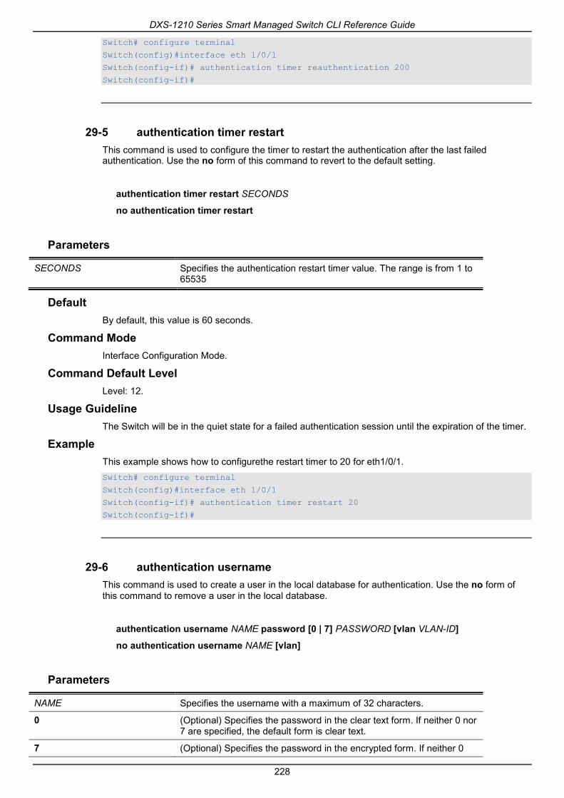
DXS-1210 Series Smart Managed Switch CLI Reference Guide
228
Switch# configure terminal
Switch(config)#interface eth 1/0/1
Switch(config-if)# authentication timer reauthentication 200
Switch(config-if)#
29-5 authentication timer restart This command is used to configure the timer to restart the authentication after the last failed authentication. Use the no form of this command to revert to the default setting.
authentication timer restart SECONDS
no authentication timer restart
Parameters
SECONDS Specifies the authentication restart timer value. The range is from 1 to 65535
Default By default, this value is 60 seconds.
Command Mode Interface Configuration Mode.
Command Default Level Level: 12.
Usage Guideline The Switch will be in the quiet state for a failed authentication session until the expiration of the timer.
Example This example shows how to configurethe restart timer to 20 for eth1/0/1. Switch# configure terminal
Switch(config)#interface eth 1/0/1
Switch(config-if)# authentication timer restart 20
Switch(config-if)#
29-6 authentication username This command is used to create a user in the local database for authentication. Use the no form of this command to remove a user in the local database.
authentication username NAME password [0 | 7] PASSWORD [vlan VLAN-ID]
no authentication username NAME [vlan]
Parameters
NAME Specifies the username with a maximum of 32 characters.
0 (Optional) Specifies the password in the clear text form. If neither 0 nor 7 are specified, the default form is clear text.
7 (Optional) Specifies the password in the encrypted form. If neither 0

DXS-1210 Series Smart Managed Switch CLI Reference Guide
229
nor 7 are specified, the default form is clear text.
password STRING Specifies to set password for MAC authentication. If in the clear text form, the length of the string cannot be over 32.
vlan VLAN-ID Specifies the VLAN to be assigned.
Default None.
Command Mode Global Configuration Mode.
Command Default Level Level: 15.
Usage Guideline Use this command to configure the local database used for user authentication.
Example This example shows how to create a local account with user1 as the username and pass1 as password. Switch# configure terminal
Switch(config)# authentication username user1 password pass1
Switch(config)#
29-7 clear authentication sessions This command is used to remove authentication sessions.
clear authentication sessions {dot1x | all | interface INTERFACE-ID [dot1x] | mac-address MAC-ADDRESS}
Parameters
dot1x Specifies to clear all dot1x sessions.
all Specifies to clear all sessions.
interface INTERFACE-ID Specifies a port to clear sessions.
mac-address MAC-ADDRESS Specifies a specific user to clear session.
Default None.
Command Mode Privileged EXEC Mode.
Command Default Level Level: 12.
Usage Guideline Use this command to clear the authentication sessions.
Example This example shows how to remove authentication sessions on Ethernet port 1/0/1.

DXS-1210 Series Smart Managed Switch CLI Reference Guide
230
Switch# clear authentication sessions interface eth 1/0/1
Switch#
29-8 authentication mac-move deny This command is used to disable MAC move on the Switch. Use the no form of this command to revert to the default setting.
authentication mac-move deny
no authentication mac-move deny
Parameters None.
Default By default, this option is permitted.
Command Mode Global Configuration Mode.
Command Default Level Level: 12.
Usage Guideline This command control whether to allow authenticated hosts to do roaming across different switch ports. This command only controls whether a host which is authenticated at a port set to multi-auth mode is allowed to move to another port.
If a station is allowed to move, there are two situations. It may either need to be re-authenticated or directly moved to the new port without re-authentication based on the following rule. If the new port has the same authentication configuration as the original port, then re-authentication is not needed. The host will inherit the same authorization attributes with new port. The authenticated host can do roaming from port 1 to port 2, and inherit the authorization attributes without re-authentication. If the new port has the different authentication configuration as the original port, then re-authentication is needed. The authenticated host on port 1 can move and re-authenticated by port 2. If the new port has no authentication method enabled, then the station is directly moved to the new port. The session with the original port is removed. The authenticated host on port 1 can be moved to port 2.
If MAC move is disabled and an authenticated host moves to another port, then this is treated as a violation error.
Example This example shows how to enable MAC move on the Switch. Switch# configure terminal
Switch(config)#authentication mac-move deny
Switch(config)#
29-9 authorization disable This command is used to disable the acceptance of the authorized configuration. Use the no form to enable the acceptance of the authorized configuration.
authorization disable
no authorization disable

DXS-1210 Series Smart Managed Switch CLI Reference Guide
231
Parameters None.
Default By default, this option is enabled.
Command Mode Global Configuration Mode.
Command Default Level Level: 12.
Usage Guideline The command is used to enable or disable the acceptance of an authorized configuration. When authorization is enabled for authentication, the authorized attributes (for example VLAN, 802.1p default priority, bandwidth, and ACL) assigned by the RADIUS server will be accepted if the authorization status is enabled. Bandwidth and ACL are assigned on a per-port basis. If in the multi-auth mode, VLAN and 802.1p are assigned on a per-host basis. Otherwise, Bandwidth and ACL are assigned on a per-port basis.
Example This example shows how to enable the authorization status. Switch# configure terminal
Switch(config)#no authorization disable
Switch(config)#
29-10 show authentication sessions This command is used to display authentication information.
show authentication sessions [dot1x | interface INTERFACE-ID [, | -] [dot1x] | mac-address MAC-ADDRESS]
Parameters
dot1x (Optional) Specifies to display all dot1x sessions.
interface INTERFACE-ID (Optional) Specifies a port to display.
, (Optional)Specifies a series of interfaces, or separate a range of interfaces from a previous range. No space is allowed before and after the comma.
- (Optional)Specifies a range of interfaces. No space is allowed before and after the hyphen.
mac-address MAC-ADDRESS (Optional) Specifies to display a specific user.
Default None.
Command Mode EXEC Mode or Any Configuration Mode.
Command Default Level Level: 1.
Usage Guideline

DXS-1210 Series Smart Managed Switch CLI Reference Guide
232
Use this command without parameters to display the sessions associated with all ports.
Example This example shows how to display sessions on Ethernet port 1/0/1. Switch# show authentication sessions interface eth 1/0/1
Interface: eth1/0/1
MAC Address: 00-16-76-35-1A-38
Authentication VLAN: 1
Authentication Username: Administrator
Assigned Priority: 0
Assigned Ingress Bandwidth : 0 kbps
Assigned Egress Bandwidth : 0 kbps
802.1X Authenticator State: HELD
802.1X Backend State : IDLE
Total Authenticating Hosts: 0
Total Authenticated Hosts: 1
Total Blocked Hosts: 0
Switch#
Display Parameters
Interface The authentication host received interface.
MAC Address The MAC address of authentication host.
Authentication VLAN The original VLAN of the host start authentication.
Authentication State The authentication status of host. Start: Host received, but no any authentication start. Initialization: Authentication resource ready, but no new authentication start. Authenticating: Host is under authenticating. Failure: Authentication failure. Success: Host pass authentication.
Accounting Session ID The accounting session ID that used to do accounting after authenticated.
Authentication Username It indicates the user name of host. It's not available while the host is selected by MAC-Auth.
Client IP Address It indicates the address of the client associates. It's only available while the host is selected by Web-Auth or JWAC.
Assigned VID Effectively assigned VLAN ID that was authorized after the host passed authentication.
Assigned Priority Effectively assigned priority that was authorized after the host passed authentication.
Assigned Ingress Bandwidth Effectively assigned ingress that was authorized after the host passed authentication.
Assigned Egress Bandwidth Effectively assigned egress that was authorized after the host passed authentication.
Method The Authentication method, such as 802.1X, MAC-Auth, Web-Auth, JWAC,and so on.
State The method authentication state.

DXS-1210 Series Smart Managed Switch CLI Reference Guide
233
Authenticating: Host is under authentication by this method. Success: Host pass this method authentication. Selected: This method’s authentication result is taken and parsed by system for the host. Failure: Host fail at this method authentication. NoInformation: Authentication info is unavailable.
Aging Time/Block Time AgingTime: Specifies a time period during which an authenticated host will be kept in an authenticated state. When the aging time has timed-out, the host will be moved back to an unauthenticated state. BlockedTime: If a host fails to pass the authentication, the next authentication will not start within the block time unless the user clears the entry state manually.
Idle Time IdleTime: Indicates the leftover time of an authenticated session that will be terminated if the session sustains no activity for the configured period of time. It is only available for WEB sessions.
802.1X Authenticator State Indicates the 802.1X authenticator PAE state: It can be one of the following values: INITIALIZE: Indicates the authenticator is initializing the state machine and ready to authenticate the supplicant. DISCONNECTED: Indicates that the state machine initialization has finished, but no supplicant connects to this port. CONNECTING: Indicates that the Switch has detected a supplicant connecting to this port. The PAE will attempt to establish communication with a supplicant. AUTHENTICATING: Indicates that a supplicant is being authenticated. AUTHENTICATED: Indicates that the Authenticator has successfully authenticated the supplicant. ABORTING:Indicates that the authentication procedure is being prematurely aborted due to the receipt of a re-authentication request, an EAPOL-Start frame, an EAPOL-Logoff frame, or an authentication timeout. HELD:Indicates that the state machine ignores and discards all EAPOL packets in order to discourage brute force attacks. This state is entered from the AUTHENTICATING state following an authentication failure. FORCE_AUTH:Indicates that the supplicant is always authorized. FORCE_UNAUTH:Indicates that the supplicant is always unauthorized.
802.1X Backend State Indicates the 802.1X backend PAE state. It can be one of the following values: REQUEST:Indicates that the state machine has received an EAP request packet from the authentication server and is relaying that packet to the Supplicant as an EAPOL-encapsulated frame. RESPONSE:Indicates that the state machine has received an EAPOL-encapsulated EAP Response packet from the supplicant and is relaying the EAP packet to the authentication Server. SUCCESS:Indicates that the authentication server has confirmed that the supplicant is a legal client. The backend state machine will notify the authenticator PAE state machine and the supplicant. FAIL:Indicates that the authentication server has confirmed the supplicant is an illegal client. The backend state machine will notify the authenticator PAE state machine and the supplicant. TIMEOUT:Indicates that the authentication server or supplicant has time out. IDLE:In this state, the state machine is waiting for the Authenticator state machine to signal the start of a new authentication session. INITIALIZE:Indicates the authenticator is initializing the state machine.

DXS-1210 Series Smart Managed Switch CLI Reference Guide
234

DXS-1210 Series Smart Managed Switch CLI Reference Guide
235
30. Port Security Commands 30-1 clear port-security
This command is used to delete the auto-learned secured MAC addresses.
clear port-security {all | {address MAC-ADDR | interface INTERFACE-ID [, | -]}}
Parameters
all Specifies to delete all auto-learned secured entries.
address MAC-ADDR Specifies to delete the specified auto -learned secured entry based on the MAC address entered.
interface INTERFACE-ID Specifies to delete all auto-learned secured entries on the specified physical interface.
, (Optional)Specifies a series of interfaces, or separate a range of interfaces from a previous range. No space is allowed before and after the comma.
- (Optional)Specifies a range of interfaces. No space is allowed before and after the hyphen.
Default None.
Command Mode Privileged EXEC Mode.
Command Default Level Level: 12.
Usage Guideline This command clears auto-learned secured entries, either dynamic or permanent.
Example This example shows how to remove a specific secure address from the MAC address table. Switch# clear port-security address 0080.0070.0007
Switch#
30-2 show port-security This command is used to display the current port security settings.
show port-security [ [[interface INTERFACE-ID [, | -]] | [address] ]
Parameters
INTEFACE-ID Specifies the ID of the interface to be displayed.
, (Optional) Specifies a series of interfaces, or separate a range of interfaces from a previous range. No space is allowed before and after the comma.
- (Optional) Specifies a range of interfaces. No space is allowed before

DXS-1210 Series Smart Managed Switch CLI Reference Guide
236
and after the hyphen.
address Specifies to display all the secure MAC addresses, including both configured and learned entries.
Default None.
Command Mode EXEC Mode or Any Configuration Mode.
Command Default Level Level: 1.
Usage Guideline This command is used to display the current port security settings.
Example This example shows how to display the port security settings of interfaces eth1/0/1 to eth1/0/3. Switch# show port-security interface eth 1/0/1-3
Interface No. : eth1/0/1
Max No. : 32
Curr No. : 0
Violation Action : Protect
Violation Count : -
Security Mode : DeleteOnTimeout
Admin State : Disabled
Current State : -
Aging Time : 0
Aging Type : Absolute
Interface No. : eth1/0/2
Max No. : 32
Curr No. : 0
Violation Action : Protect
Violation Count : -
Security Mode : DeleteOnTimeout
Admin State : Disabled
Current State : -
Aging Time : 0
Aging Type : Absolute
Interface No. : eth1/0/3
Max No. : 32
Curr No. : 0
Violation Action : Protect
Violation Count : -
Security Mode : DeleteOnTimeout
Admin State : Disabled
Current State : -
Aging Time : 0
Aging Type : Absolute
Switch#

DXS-1210 Series Smart Managed Switch CLI Reference Guide
237
30-3 snmp-server enable traps port-security This command is used to enable sending SNMP notifications for port security address violation. Use the no form of this command to disable sending SNMP notifications.
snmp-server enable traps port-security [trap-rate TRAP-RATE]
no snmp-server enable traps port-security [trap-rate]
Parameters
trap-rate TRAP-RATE (Optional) Specifies the number of traps per second. The range is from 0 to 1000. The default value ("0") indicates an SNMP trap to be generated for every security violation.
Default By default, this option is disabled.
Command Mode Global Configuration Mode.
Command Default Level Level: 12.
Usage Guideline Use this command to enable or disable SNMP notifications for port security address violation, and configure the number of traps per second.
Example This example shows how to enable sending trap for port security address violation and set the number of traps per second to 3. Switch# configure terminal
Switch(config)# snmp-server enable traps port-security
Switch(config)#
30-4 switchport port-security This command is used to configure the port security settings to restrict the number of users that are allowed to gain access rights to a port. Use the no form of this command to disable port security or to delete a secure MAC address.
switchport port-security [maximum VALUE | violation {protect | restrict | shutdown} | mode {permanent | delete-on-timeout} | mac-address [permanent] MAC-ADDRESS [vlan VLAN-ID]]
no switchport port-security [maximum | violation | mode | mac-address [permanent] MAC-ADDRESS [vlan VLAN-ID]]
Parameters
maximum VALUE (Optional) Specifies to set the maximum number of secure MAC addresses allowed. If not specified, the default value is 32. The valid range is from 0 to 6656.
protect (Optional) Specifies to drop all packets from the insecure hosts at the port-security process level, but does not increment the security-violation count.
restrict (Optional) Specifies to drop all packets from the insecure hosts at the

DXS-1210 Series Smart Managed Switch CLI Reference Guide
238
port-security process level and increments the security-violation count and record the system log.
shutdown (Optional) Specifies to shut down the port if there is a security violation and record the system log.
permanent (Optional) Specifies that under this mode, all learned MAC addresses will not be purged out unless the user manually deletes those entries.
delete-on-timeout (Optional) Specifies that under this mode, all learned MAC addresses will be purged out when an entry is aged out or when the user manually deletes these entries.
mac-address MAC-ADDRESS (Optional) Specifies to add a secure MAC address to gain port access rights.
permanent (Optional) Specifies to set the secure permanent configured MAC address of the port. This entry is same as the one learnt under the permanent mode.
vlan VLAN-ID (Optional) Specifies a VLAN. If no VLAN is specified, the MAC address will be set with a PVID.
Default By default, this option is disabled.
Command Mode Interface Configuration Mode.
Command Default Level Level: 12.
Usage Guideline When port security is enabled, if the port mode is configured as delete-on-timeout, the port will automatically learn the dynamic secured entry which will be timed out. These entries will be aged out based on the setting specified by the switchport port-security aging command. If the port mode is permanent, the port will automatically learn permanent secured entries which will not be timed out. The auto-learned permanent secured entry will be stored in the running configuration.
As the port mode-security state is changed, the violation counts will be cleared, and the auto-permanent entries will be converted to corresponding dynamic entries. As the port-security state is changed to disabled, the auto-learned secured entries, either dynamic or permanent with its violation counts are cleared. As the related VLAN configuration is changed, the auto-learned dynamic secured entries are cleared.
Permanent secured entry will be kept in the running configuration and can be stored to the NVRAM by using the copy command. The user configured secure MAC addresses are counted in the maximum number of MAC addresses on a port.
As a permanent secured entry of a port security enabled port, the MAC address cannot be moved to another port.
When the maximum setting is changed, the learned address will remain unchanged when the maximum number increases. If the maximum number is changed to a lower value which is lower than the existing entry number, the command is rejected.
A port-security enabled port has the following restrictions.
• The port security function cannot be enabled simultaneously with 802.1X, MAC (MAC-based Access Control), JWAC, WAC and IMPB, that provides more advanced security capabilities.
• If a port is specified as the destination port for the mirroring function, the port security function cannot be enabled.
• If the port is a link aggregation member port, the port security function cannot be enabled.
When the maximum number of secured users is exceeded, one of the following actions can occur:
• Protect - When the number of port secure MAC addresses reaches the maximum number of users that is allowed on the port, the packets with the unknown source address is dropped until some secured entry is removed to release the space.

DXS-1210 Series Smart Managed Switch CLI Reference Guide
239
• Restrict - A port security violation restricts data and causes the security violation counter to increment.
• Shutdown - The interface is disabled, based on errors, when a security violation occurs.
Example This example shows how to configure the port security mode to be permanent, specifying that a maximum of 5 secure MAC addresses are allowed on the port. Switch# configure terminal
Switch(config)#interface eth 1/0/1
Switch(config-if)# switchport port-security mode permanent
Switch(config-if)# switchport port-security maximum 5
Switch(config-if)#
This example shows how to manually add the secure MAC addresses 00-00-12-34-56-78 with VID 5 at interface eth1/0/1. Switch# configure terminal
Switch(config)#interface eth 1/0/1
Switch(config-if)# switchport port-security mac-address 00-00-12-34-56-78 vlan 5
Switch(config-if)#
This example shows how to configure the Switch to drop all packets from the insecure hosts at the port-security process level and increment the securityviolation counter if a security violation is detected. Switch# configure terminal
Switch(config)#interface eth 1/0/1
Switch(config-if)# switchport port-security violation restrict
Switch(config-if)#
30-5 switchport port-security aging This command is used to configure the aging time for auto-learned dynamic secure addresses on an interface. Use the no form of this command to revert to the default settings.
switchport port-security aging {time MINUTES | type {absolute | inactivity}}
no switchport port-security aging {time | type}
Parameters
MINUTES Specifies the aging time for the auto-learned dynamic secured address on this port. Its range is from 1 to 1440 in minutes.
type Specifies to set the aging type.
absolute Specifies to set absolute aging type. All the secure addresses on this port age out exactly after the time specified and is removed from the secure address list. This is the default type.
inactivity Specifies to set the inactivity aging type. The secure addresses on this port age out only if there is no data traffic from the secure source address for the specified time period.
Default By default, the port security aging feature is disabled.
The default time is 0 minutes.

DXS-1210 Series Smart Managed Switch CLI Reference Guide
240
The default aging type is absolute.
Command Mode Interface Configuration Mode.
Command Default Level Level: 12.
Usage Guideline Use this command to disable the ageing or set the ageing time for auto-learned dynamic secured entries. In order for the inactivity setting to take effect, the FDB table ageing function must be enabled.
Example This example shows how to apply the aging time for automatically learned secure MAC addresses for interface eth1/0/1. Switch# configure terminal
Switch(config)#interface eth 1/0/1
Switch(config-if)# switchport port-security aging time 1
Switch(config-if)#
This example shows how to configure the port security aging time type for interface eth1/0/1. Switch# configure terminal
Switch(config)#interface eth 1/0/1
Switch(config-if)# switchport port-security aging type inactivity
Switch(config-if)#
30-6 port-security limit This command is used to configure the maximum secure MAC address number on the system. Use the no form of this command to revert to the default setting.
port-security limit globalVALUE
no port-security limit global
Parameters
VALUE Specifies the maximum number of port security entries that can be learned on the system. The range is from 1 to 6656. If the setting is smaller than the number of current learned entries, the command will be rejected.
Default None.
Command Mode Global Configuration Mode.
Command Default Level Level: 12.
Usage Guideline Use this command to set the limit on the port security entry number which can be learned on a system.
Example This example shows how to configure the maximum secure MAC address number for the system.

DXS-1210 Series Smart Managed Switch CLI Reference Guide
241
Switch# configure terminal
Switch(config)#port-security limit global 100
Switch(config)#
30-7 show port-security global-settings This command is used to display port security global settings.
show port-security global-settings
Parameters None
Default None.
Command Mode EXEC Mode
Any Configuration Mode.
Command Default Level Level: 1.
Usage Guideline Use this command to display port security global settings.
Example This example shows how to display port security global settings. Switch# show port-security global-settings
Trap State : Disabled
Trap Rate : 0
System Maximum Address : No Limit
Switch#
30-8 show snmp-server traps port-security This command is used to display port security traps is enabled or not.
show snmp-server traps port-security
Parameters None
Default None.
Command Mode EXEC Mode
Any Configuration Mode.

DXS-1210 Series Smart Managed Switch CLI Reference Guide
242
Command Default Level Level: 1.
Usage Guideline Use this command to display port security traps states.
Example This example shows how to display port security traps states. Switch# show snmp-server traps port-security
port-security : Disabled
Switch#

DXS-1210 Series Smart Managed Switch CLI Reference Guide
243
31. Power Saving Commands 31-1 dim led
This command is used to disable the port LED function. Use the no form of this command to restore the LED function.
dim led
no dim led
Parameters None.
Default By default, this option is disabled.
Command Mode Global Configuration Mode.
Command Default Level Level: 12.
Usage Guideline Use this command to turn off the port LED function. Use the no form of this command to restore the LED function. When the port LED function is disabled, LEDs used to illustrate port status are all turned off to save power.
Example This example shows how to disable the port LED function: Switch# configure terminal
Switch(config)#dim led
Switch(config)#
31-2 power-saving This command is used to enable individual power saving functions. Use the no form of this command to disable these functions.
power-saving {port-shutdown | dim-led | hibernation}
no power-saving {port-shutdown | dim-led | hibernation}
Parameters
dim-led Specifies that power saving will be applied by scheduled dimming LEDs.
port-shutdown Specifies that power saving will be applied by scheduled port shutdown.
hibernation Specifies that power saving will be applied by scheduled system hibernation. This parameter can only be used when the stacking is disabled.
Default

DXS-1210 Series Smart Managed Switch CLI Reference Guide
244
By default, all the options are disabled.
Command Mode Global Configuration Mode.
Command Default Level Level: 12.
Usage Guideline The user can enable or disable dimming LEDs, port shutdown, and hibernation using this command.
When dim LED is enabled, the device will turn off all the port’s LEDs in the specified time range to save power.
When port shutdown is enabled, the device will shut off all ports in the specified time range to save power.
When hibernation is enabled, the device will enter the hibernation mode in the specified time range to save power. This parameter can only be used when the stacking is disabled.
Example This example shows how to enable power saving by shutting off the Switch’s ports and toggle the Switch into the hibernation mode. Switch# configure terminal
Switch(config)#power-saving port-shutdown
Switch(config)# power-saving hibernation
Switch(config)#
31-3 power-saving eee This command is used to enable the Energy-Efficient Ethernet (EEE) function on the specified port(s). Use the no form of this command to disable the EEE function.
power-saving eee
no power-saving eee
Parameters None.
Default By default, this option is disabled.
Command Mode Interface Configuration Mode.
Command Default Level Level: 12.
Usage Guideline Use this command to enable or disable the specified port’s EEE power saving function. The Energy-Efficient Ethernet (EEE) power-saving mode saves power consumption while a link is up when there is low utilization of packet traffic. The physical interface will enter into a Low Power Idle (LPI) mode when there is no data to be transmitted. In the EEE power-saving mode, power consumption is scalable to the actual bandwidth utilization.
Example This example shows how to enable the EEE power saving function.

DXS-1210 Series Smart Managed Switch CLI Reference Guide
245
Switch# configure terminal
Switch(config)#interface eth1/0/1
Switch(config-if)# power-saving eee
Switch(config-if)#
31-4 power-saving dim-led time-range This command is used to configure the timerange profile for the dim LED schedule. Use the no form of this command to delete the specified timerange profile.
power-saving dim-led time-range PROFILE-NAME
no power-saving dim-led time-range PROFILE-NAME
Parameters
PROFILE-NAME Specifies the name of the timerange profile to be configured. The maximum length is 32 characters.
Default None.
Command Mode Global Configuration Mode.
Command Default Level Level: 12.
Usage Guideline Use this command to add or delete a time range profile for the dim LED schedule. When the schedule is up, all port’s LED will be turned off.
Example This example shows how to add a time-range profile for the dim LED schedule. Switch# configure terminal
Switch(config)#power-saving dim-led time-range off-duty
Switch(config)#
31-5 power-saving hibernation time-range This command is used to configure the timerange profile for the system hibernation schedule. Use the no form of this command to delete the specified timerange profile.
power-saving hibernation time-range PROFILE-NAME
no power-saving hibernation time-range PROFILE-NAME
Parameters
PROFILE-NAME Specifies the name of the timerange profile to be configured. The maximum length is 32 characters.
Default

DXS-1210 Series Smart Managed Switch CLI Reference Guide
246
None.
Command Mode Global Configuration Mode.
Command Default Level Level: 12.
Usage Guideline Use this command to add or delete a time range profile for the system hibernation schedule. When the system enters the hibernation mode, the Switch will go into a low power state and idle. It will shut down all the ports and LEDs, all network function will be disabled, and only the console connection will work via the RS232 port. If the Switch is an endpoint type Power Sourcing Equipment (PSE), the Switch will not provide power to the port. This command can only be used when the stacking is disabled.
Example This example shows how to add a timerange profile for the hibernation schedule. Switch# configure terminal
Switch(config)#power-saving hibernation time-range off-duty
Switch(config)#
31-6 power-saving shutdown time-range This command is used to configure the timerange profile for the portshutdown schedule. Use the no form of this command to delete the specified timerange profile.
power-saving shutdown time-range PROFILE-NAME
no power-saving shutdown time-range PROFILE-NAME
Parameters
PROFILE-NAME Specifies the name of the timerange profile to be configured. The maximum length is 32 characters.
Default None.
Command Mode Interface Configuration Mode.
Command Default Level Level: 12.
Usage Guideline Use this command to add or delete a time range profile for the port shutdown schedule. When the schedule is up, the specific port will be disabled.
Example This example shows how to add a timerange profile for the port shutdown schedule. Switch# configure terminal
Switch(config)#interface eth1/0/1
Switch(config-if)# power-saving shutdown time-range off-duty
Switch(config-if)#
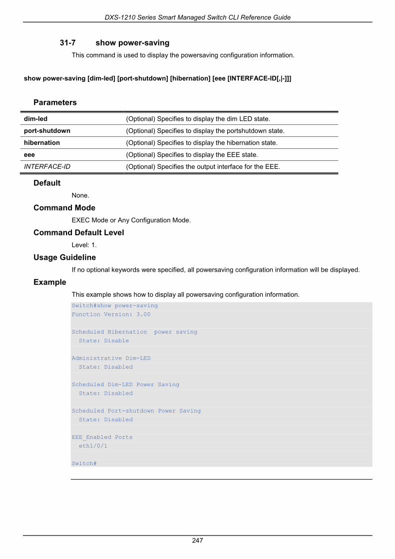
DXS-1210 Series Smart Managed Switch CLI Reference Guide
247
31-7 show power-saving This command is used to display the powersaving configuration information.
show power-saving [dim-led] [port-shutdown] [hibernation] [eee [INTERFACE-ID[,|-]]]
Parameters
dim-led (Optional) Specifies to display the dim LED state.
port-shutdown (Optional) Specifies to display the portshutdown state.
hibernation (Optional) Specifies to display the hibernation state.
eee (Optional) Specifies to display the EEE state.
INTERFACE-ID (Optional) Specifies the output interface for the EEE.
Default None.
Command Mode EXEC Mode or Any Configuration Mode.
Command Default Level Level: 1.
Usage Guideline If no optional keywords were specified, all powersaving configuration information will be displayed.
Example This example shows how to display all powersaving configuration information. Switch#show power-saving
Function Version: 3.00
Scheduled Hibernation power saving
State: Disable
Administrative Dim-LED
State: Disabled
Scheduled Dim-LED Power Saving
State: Disabled
Scheduled Port-shutdown Power Saving
State: Disabled
EEE_Enabled Ports
eth1/0/1
Switch#

DXS-1210 Series Smart Managed Switch CLI Reference Guide
248

DXS-1210 Series Smart Managed Switch CLI Reference Guide
249
32. Protocol Independent Commands 32-1 ip route
This command is used to create a static route entry. Use the no form of this command to remove a static route entry.
ip route NETWORK-PREFIX NETWORK-MASKIP-ADDRESS [primary | backup]
no ip route NETWORK-PREFIX NETWORK-MASKIP-ADDRESS
Parameters
NETWORK-PREFIX Specifies the network address.
NETWORK-MASK Specifies the network mask.
IP-ADDRESS Specifies the IP address of the next hop that can be used to reach destination network.
primary (Optional) Specifies the route as the primary route to the destination.
backup (Optional) Specifies the route as the backup route to the destination.
Default None.
Command Mode Global Configuration Mode.
Command Default Level Level: 12.
Usage Guideline Use this command to create an IP static route. Floating static route is supported. This means that there could be two routes with the same destination network address and different next hop. If primary or backup is not specified, the static route will be automatically determined to be a primary route or a backup route. Primary route has higher priority than backup route, and is always be used for forwarding when it is active. When primary is down, the backup route will be used.
Example This example shows how to add a static route entry for 20.0.0.0/8 with the next-hop 10.1.1.254. Switch# configure terminal
Switch(config)#ip route 20.0.0.0 255.0.0.0 10.1.1.254
Switch(config)#
32-2 ipv6 route This command is used to create an IPv6 static route entry. Use the no form of this command to remove an IPv6 static route entry.
ipv6 route {default | NETWORK-PREFIX/PREFIX-LENGTH} [INTERFACE-ID] NEXT-HOP-ADDRESS [primary | backup]
no ipv6 route {default | NETWORK-PREFIX/PREFIX-LENGTH} [INTERFACE-ID] NEXT-HOP-ADDRESS

DXS-1210 Series Smart Managed Switch CLI Reference Guide
250
Parameters
default Specifies to add or delete a default route.
NETWORK-PREFIX/PREFIX-LENGTH
Specifies the network prefix and the prefix length of the static route.
INTERFACE-ID (Optional) Specifies the forwarding interface for routing the packet.
NEXT-HOP-ADDRESS (Optional) Specifies the IPv6 address of the next hop to reach the destination network. If the address is a link-local address, then the interface ID also need to be specified.
primary (Optional) Specifies the route as the primary route to the destination.
backup (Optional) Specifies the route as the backup route to the destination.
Default None.
Command Mode Global Configuration Mode.
Command Default Level Level: 12.
Usage Guideline Floating static route is supported. This means that there could be two routes with same destination network address and different next hop. If primary or backup is not specified, the static route will be automatically determined to be a primary route or a backup route. Primary route has higher priority than backup route, and is always be used for forwarding when it is active. When primary is down, the backup route will be used.
Example This example shows how to create a static route destined to the network where proxy server resides. Switch# configure terminal
Switch(config)#ipv6 route 2001:0101::/32 vlan 1 fe80::0000:00ff:1111:2233
Switch(config)#
32-3 show ip route This command is used to display the entry in the routing table.
show ip route [[IP-ADDRESS [MASK] | connected | static] | hardware]
Parameters
IP-ADDRESS (Optional) Specifies the network address of which routing information should be displayed.
MASK (Optional) Specifies the subnet mask for the specified network.
connection (Optional) Specifies to display directly connected route.
static (Optional) Specifies to display the static route.
hardware (Optional) Specifies to display the routes that have been written into chip.
Default None.

DXS-1210 Series Smart Managed Switch CLI Reference Guide
251
Command Mode EXEC Mode or Any Configuration Mode.
Command Default Level Level: 1.
Usage Guideline Use this command to display the best routes that are currently at work.
Example This example shows how to display the routing table. Switch#show ip route
Code: C - connected, S - static
* - candidate default
Gateway of last resort is not set
C 10.0.0.0/8 is directly connected, vlan1
Total Entries: 1
Switch#
32-4 show ip route summary This command is used to display the brief information for the working routing entries.
show ip route summary
Parameters None.
Default None.
Command Mode EXEC Mode or Any Configuration Mode.
Command Default Level Level: 1.
Usage Guideline Use this command to display the brief information for the working routing entries.
Example This example shows how to display the IP route entries.

DXS-1210 Series Smart Managed Switch CLI Reference Guide
252
Switch#show ip route summary
Route Source Networks
Connected 1
Static 0
Total 1
Switch#
32-5 show ipv6 route This command is used to display the entry in routing table.
show ipv6 route {[IPV6-ADDRESS | NETWORK-PREFIX/PREFIX-LENGTH [longer-prefixes] | INTERFACE-ID | connected | static] [database] | hardware}
Parameters
IPV6-ADDRESS (Optional) Specifies an IPv6 address to find a longest prefix matched IPv6 route.
NETWORK-PREFIX (Optional) Specifies the network address of which routing information should be displayed.
PREFIX-LENGTH (Optional) Specifies the prefix length for the specified network
longer-prefixes (Optional) Specifies to display the route and all of the more specific routes.
INTERFACE-ID (Optional) Specifies the interface type.
connected (Optional) Specifies to display directly connected route.
static (Optional) Specifies to display the static route.
database (Optional) Specifies to display all the related entries in the routing database instead of just the best route.
hardware Specifies to display the routes that have been written into chip.
Default None.
Command Mode EXEC Mode or Any Configuration Mode.
Command Default Level Level: 1.
Usage Guideline Use this command to display the best routes that are currently at work.
Example This example shows how to display the routing entries for IPv6.

DXS-1210 Series Smart Managed Switch CLI Reference Guide
253
Switch# show ipv6 route
IPv6 Routing Table
Code: C - connected, S - static
C 2000:410:1::/64 [0/1] is directly connected, vlan1
S 2001:0101::/64 [1/1] via fe80::0000:00ff:1111:2233, vlan1
S 2001:0102::/64 [1/1] via fe80::0000:00ff:1111:2233, vlan1
Total Entries: 3 entries, 3 routes
Switch#
This example shows how to display the static routing entries for IPv6. Switch# show ipv6 route static
IPv6 Routing Table
Code: C - connected, S - static
S 2001:0101::/64 [1/1] via fe80::0000:00ff:1111:2233, vlan1
S 2001:0102::/64 [1/1] via fe80::0000:00ff:1111:2233, vlan1
Total Entries: 2 entries, 2 routes
Switch#
32-6 show ipv6 route summary This command is used to display the current state of the IPv6 routing table.
show ipv6 route summary
Parameters None.
Default None.
Command Mode EXEC Mode or Any Configuration Mode.
Command Default Level Level: 1.
Usage Guideline When the system provides forwarding services for IPv6 traffic, it is very important and helpful to check the forwarding/routing table to understand what the traffic path will be currently in the network.
Example This example shows how to display the current state of the IPv6 routing table.
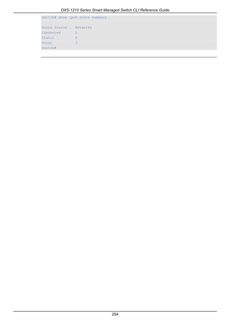
DXS-1210 Series Smart Managed Switch CLI Reference Guide
254
Switch# show ipv6 route summary
Route Source Networks
Connected 2
Static 0
Total 3
Switch#

DXS-1210 Series Smart Managed Switch CLI Reference Guide
255
33. Quality of Service (QoS) Commands 33-1 mls qos cos
This command is used to configure the default Class of Service (CoS) value of a port. Use the no form of this command to revert to the default settings.
mls qos cos {COS-VALUE | override}
no mls qos cos
Parameters
COS-VALUE Specifies to assign a default CoS value to a port. This CoS will be applied to the incoming untagged packets received by the port.
override Specifies to override the CoS of the packets. The default CoS will be applied to all incoming packets, tagged or untagged, received by the port.
Default By default, this CoS value is 0.
Command Mode Interface Configuration Mode.
Command Default Level Level: 12.
Usage Guideline When the override option is not specified, the CoS of the packets will be the packet’s CoS if the packets are tagged, and will be the port default CoS if the packet is untagged.
When the override option is specified, the port default CoS will be applied to all packets received by the port. Use the override keyword when all incoming packets on certain ports deserve a higher or lower priority than packets that enter from other ports. Even if a port was previously set to trust DSCP or CoS, this command overrides that trust state, and all CoS values on the incoming packets are changed to the default CoS value that is configured with the mls qos cos command. If an incoming packet is tagged, the CoS value of the packet is modified at the ingress port.
Example This example shows how the default CoS of Ethernet port 1/0/1 is set to 3. Switch# configure terminal
Switch(config)#interface eth 1/0/1
switch(config-if)# mls qos cos 3
switch(config-if)#
33-2 mls qos map dscp-cos This command is used to define a Differentiated Services Code Point (DSCP)-to-class of service (CoS) map. Use the no form of this command to revert to the default setting.
mls qos map dscp-cos DSCP-LIST to COS-VALUE
no mls qos map dscp-cos DSCP-LIST

DXS-1210 Series Smart Managed Switch CLI Reference Guide
256
Parameters
dscp-cos DSCP-LIST to COS-VALUE
Specifies the list of DSCP code points to be mapped to a CoS value. The range is from 0 to 63. The series of DSCPs can be separated by commas (,) or hyphens (-) with no spaces or hyphens before and after.
DSCP-LIST Specifies the range of DSCP values.
Default CoS Value: 0 1 2 3 4 5 6 7
DSCP Value: 0-7 8-15 16-23 24-31 32-39 40-47 48-55 56-63
Command Mode Interface Configuration Mode.
Command Default Level Level: 12.
Usage Guideline The DSCP to CoS map is used by a DSCP trust port to map a DSCP value to an internal CoS value. In turn this CoS value is then mapped to the CoS queue based on the CoS to queue map configured by the priority-queue cos-map command.
Example This example shows how to configure the DSCP to CoS map for mapping DSCP 12, 16, and 18 to CoS 1 for eth2/0/6. Switch# configure terminal
Switch(config)#interface eth 1/0/6
Switch(config-if)# mls qos map dscp-cos 12,16,18 to 1
Switch(config-if)#
33-3 mls qos scheduler This command is used to configure the scheduling mechanism. Use the no form of this command to reset the packet scheduling mechanism to the default.
mls qos scheduler {sp | rr | wrr | wdrr}
no mls qos scheduler
Parameters
sp Specifies that all queues are in strict priority scheduling.
rr Specifies that all queues are in round-robin scheduling.
wrr Specifies the queues in the frame count weighted round-robin scheduling. If the weight of a queue be configured to zero, the queue is in the SP scheduling mode.
wdrr Specifies the queues of all ports in the frame length (quantum) weighted deficit round-robin scheduling. If the weight of a queue be configured to zero, the queue is in the SP scheduling mode.
Default The default queue scheduling algorithm is WRR.
Command Mode Interface Configuration Mode.

DXS-1210 Series Smart Managed Switch CLI Reference Guide
257
Command Default Level Level: 12.
Usage Guideline Specify schedule algorithms to WRR, SP, RR or WDRR for the output queue. By default, the output queue scheduling algorithm is WRR. WDRR operates by serving an accumulated set of backlogged credits in the transmit queue in a round robin order. Initially, each queue sets its credit counter to a configurable quantum value. Every time a packet from a CoS queue is sent, the size of the packet is subtracted from the corresponding credit counter and the service right is turned over to the next lower CoS queue. When the credit counter drops below 0, the queue is no longer serviced until its credits are replenished. When the credit counters of all CoS queues reaches 0, the credit counters will be replenished at that time.
All packets are serviced until their credit counter is zero or negative and the last packet is transmitted completely. When this condition happens, the credits are replenished. When the credits are replenished, a quantum of credits are added to each CoS queue credit counter. The quantum for each CoS queue may be different based on the user configuration.
To set a CoS queue in the strict priority mode, any higher priority CoS queue must also be in the strict priority mode.
WRR operates by transmitting permitted packets into the transmit queue in a round robin order. Initially, each queue sets its weight to a configurable weighting. Every time a packet from a higher priority CoS queue is sent, the corresponding weight is subtracted by 1, and the packet in the next lower CoS queue will be serviced. When the weight of a CoS queue reaches zero, the queue will not be serviced until its weight is replenished. When weights of all CoS queues reach 0, the weights get replenished at a time.
Example This example shows how to configure the queue scheduling algorithm to the strict priority mode. Switch# configure terminal
Switch(config)#interface eth 1/0/1
Switch(config-if)# mls qos scheduler sp
Switch(config-if)#
33-4 mls qos trust This command is used to configure the trust state of a port to trust either the CoS field or the DSCP field of the arriving packet for subsequent QoS operation. Use the no form of this command to revert to the default setting.
mls qos trust {cos | dscp}
no mls qos trust
Parameters
cos Specifies that the CoS bits of the arriving packets are trusted for subsequent QoS operations.
dscp Specifies that the ToS/DSCP bits, if available in the arriving packets, are trusted for subsequent operations. For non-IP packet, Layer 2 CoS information will be trusted for traffic classification.
Default By default, CoS is trusted.
Command Mode Interface Configuration Mode.

DXS-1210 Series Smart Managed Switch CLI Reference Guide
258
Command Default Level Level: 12.
Usage Guideline When the interface is set to trust DSCP, the DSCP of the arriving packet will be trusted for the subsequent QoS operations. First, the DSCP will be mapped to an internal CoS value, which will be subsequently used to determine the CoS queue. The DSCP to CoS map is configured by the mls qos map dscp-cos command. The CoS to queue map is configured by the priority-queue cos-map command. If the arriving packet is a non-IP packet, the CoS is trusted. The resulting CoS mapped from DSCP will also be the CoS in the transmitted packet.
When an interface is in the trust CoS state, the CoS of the arriving packet will be applied to the packet as the internal CoS and used to determine the CoS queue. The CoS queue is determined based on the CoS to Queue mapping table.
When a packet arrives at an 802.1Q VLAN tunnel port, the packet will be added with an outer VLAN tag in order to transmit through the VLAN tunnel. If the port is to trust CoS, then the inner tag CoS will be the internal CoS of the packet and the CoS value in the packet’s outer VLAN tag. If the MLS QoS CoS override is configured, then the CoS specified by command mls qos cos will be the internal CoS of the packet and the CoS value in the packet’s outer VLAN tag. If the port is to trust DSCP, then the CoS mapped from the DSCP code point will be the internal CoS of the packet and the CoS value in the packet’s outer VLAN tag
When a packet is received by a port, it will be initialized to a color based on the mls qos map dscp-color command if the receiving port is to trust DSCP or MLS QoS mapped CoS color if the receiving port is to trust CoS.
Example This example shows how to configure port eth1/0/1 to trust the DSCP mode. Switch# configure terminal
Switch(config)#interface eth 1/0/1
Switch(config-if)# mls qos trust dscp
Switch(config-if)#
33-5 priority-queue cos-map This command is used to define a Class of Service (CoS) to queue map. Use the no form of this command to revert to the default setting.
priority-queue cos-map QUEUE-ID COS1 [COS2 [COS3 [COS4 [COS5 [COS6 [COS7 [COS8]]]]]]]
no priority-queue cos-map
Parameters
QUEUE-ID Specifies the queue ID the CoS will be mapped.
COS1 Specifies the mapping CoS value.Valid values are from 0 to 7.
COS2…COS8 (Optional) Specifies the mapping CoS value.Valid values are from 0 to 7.
Default The default priority (CoS) to queue mapping is: 0 to 2, 1 to 0, 2 to 1, 3 to 3, 4 to 4, 5 to 5, 6 to 6, 7 to 7.
Command Mode Global Configuration Mode.
Command Default Level

DXS-1210 Series Smart Managed Switch CLI Reference Guide
259
Level: 12.
Usage Guideline When a packet is received, the packet will be given an internal CoS. This internal CoS is used to select the transmit queue based on the CoS to queue map. The CoS queue with a higher number will receivea higher priority.
Example This example shows how to assign CoS priority 3, 5 and 6 to queue 2. Switch# configure terminal
Switch(config)#priority-queue cos-map 2 3 5 6
Switch(config)#
33-6 queue rate-limit This command is used to specify or modify the bandwidth allocated for a queue. Use the no form of this commandto remove the bandwidth allocated for a queue.
queue QUEUE-ID rate-limit {MIN-BANDWIDTH-KBPS MAX-BANDWIDTH-KBPS | percent MIN-PERCENTAGE MAX-PERCENTAGE}
no queue QUEUE-ID rate-limit
Parameters
QUEUE-ID Specifies the queue ID to set minimal guaranteed and maximum bandwidth.
MIN-BANDWIDTH-KBPS Specifies the minimal guaranteed bandwidth in kilobits per second allocated to a specified queue.
MAX-BANDWIDTH-KBPS Specifies the maximum bandwidth in kilobits per second for a specified queue.
MIN-PERCENTAGE Specifies to set the minimal bandwidth by percentage. The valid range is from 1 to 100.
MAX-PERCENTAGE Specifies to set the maximum bandwidth by percentage. The valid range is from 1 to 100.
Default None.
Command Mode Interface Configuration Mode.
Command Default Level Level: 12.
Usage Guideline Use this command to configure the minimal and maximum bandwidth for a specified queue. When the minimal bandwidth is configured, the packet transmitted from the queue can be guaranteed. When the maximum bandwidth is configured, packets transmitted from the queue cannot exceed the maximum bandwidth even if the bandwidth is available.
When configuring the minimal bandwidth, the aggregate of the configured minimum bandwidth must be less than 75 percent of the interface bandwidth to make sure the configured minimal bandwidth can be guaranteed. It is not necessary to set the minimum guaranteed bandwidth for the highest strict priority queue. This is because the traffic in this queue will be serviced first if the minimal bandwidth of all queues is satisfied.
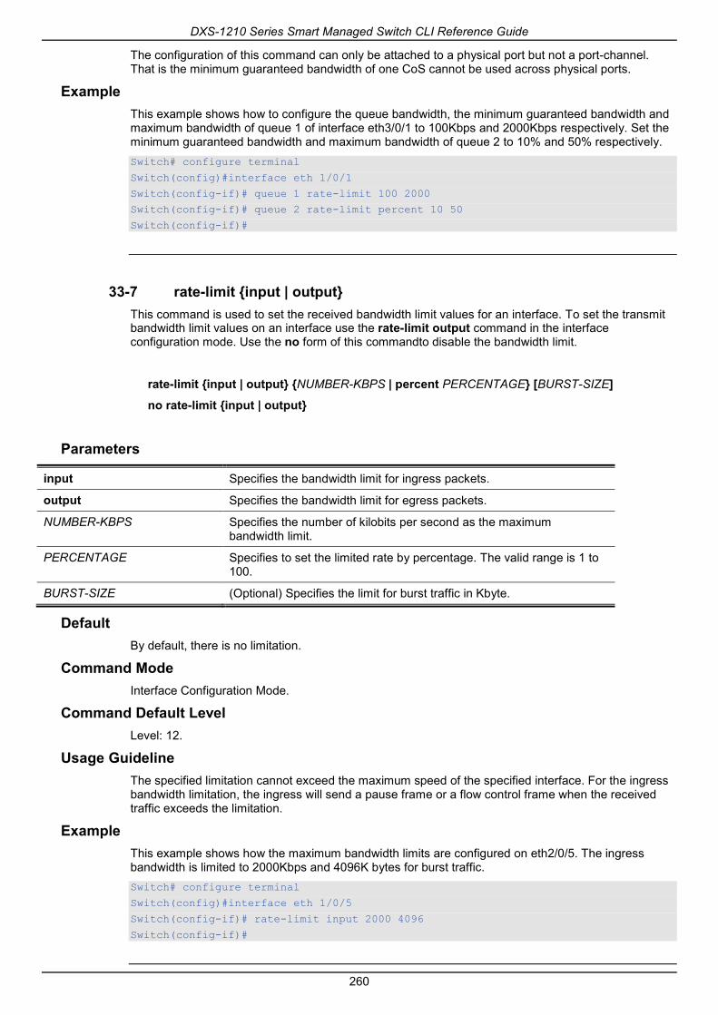
DXS-1210 Series Smart Managed Switch CLI Reference Guide
260
The configuration of this command can only be attached to a physical port but not a port-channel. That is the minimum guaranteed bandwidth of one CoS cannot be used across physical ports.
Example This example shows how to configure the queue bandwidth, the minimum guaranteed bandwidth and maximum bandwidth of queue 1 of interface eth3/0/1 to 100Kbps and 2000Kbps respectively. Set the minimum guaranteed bandwidth and maximum bandwidth of queue 2 to 10% and 50% respectively. Switch# configure terminal
Switch(config)#interface eth 1/0/1
Switch(config-if)# queue 1 rate-limit 100 2000
Switch(config-if)# queue 2 rate-limit percent 10 50
Switch(config-if)#
33-7 rate-limit {input | output} This command is used to set the received bandwidth limit values for an interface. To set the transmit bandwidth limit values on an interface use the rate-limit output command in the interface configuration mode. Use the no form of this commandto disable the bandwidth limit.
rate-limit {input | output} {NUMBER-KBPS | percent PERCENTAGE} [BURST-SIZE]
no rate-limit {input | output}
Parameters
input Specifies the bandwidth limit for ingress packets.
output Specifies the bandwidth limit for egress packets.
NUMBER-KBPS Specifies the number of kilobits per second as the maximum bandwidth limit.
PERCENTAGE Specifies to set the limited rate by percentage. The valid range is 1 to 100.
BURST-SIZE (Optional) Specifies the limit for burst traffic in Kbyte.
Default By default, there is no limitation.
Command Mode Interface Configuration Mode.
Command Default Level Level: 12.
Usage Guideline The specified limitation cannot exceed the maximum speed of the specified interface. For the ingress bandwidth limitation, the ingress will send a pause frame or a flow control frame when the received traffic exceeds the limitation.
Example This example shows how the maximum bandwidth limits are configured on eth2/0/5. The ingress bandwidth is limited to 2000Kbps and 4096K bytes for burst traffic. Switch# configure terminal
Switch(config)#interface eth 1/0/5
Switch(config-if)# rate-limit input 2000 4096
Switch(config-if)#

DXS-1210 Series Smart Managed Switch CLI Reference Guide
261
33-8 show mls qos interface This command is used to display port level QoS configurations.
show mls qos interface INTERFACE-ID [, | -] {cos | scheduler | trust | rate-limit | queue-rate-limit | dscp-cos-map }
Parameters
interface INTERFACE-ID Specifies the interface ID to display.
, (Optional)Specifies a series of interfaces, or separate a range of interfaces from a previous range. No space is allowed before and after the comma.
- (Optional)Specifies a range of interfaces. No space is allowed before and after the hyphen.
cos Specifies to displays the port default CoS.
scheduler Specifies to displays the transmit queue scheduling settings.
trust Specifies to displays the port trust State.
rate-limit Specifies to displays the bandwidth limitation configured for the port.
queue-rate-limit Specifies to displays the bandwidth allocation configured for the queue.
dscp-cos-map Specifies to displays the mapping of DSCP to CoS.
Default None.
Command Mode EXEC Mode or Any Configuration Mode.
Command Default Level Level: 1.
Usage Guideline This command is used to display port level QoS configurations.
Example This example shows how to display the default CoS for eth 1/0/2 to eth 1/0/5. Switch# show mls qos interface eth 1/0/2-5 cos
Interface CoS Override
---------- ---- ---------
eth1/0/2 3 Yes
eth1/0/3 4 No
eth1/0/4 4 No
eth1/0/5 3 No
Switch#
This example shows how to display the port trust state for eth 1/0/2 to eth 1/0/5.

DXS-1210 Series Smart Managed Switch CLI Reference Guide
262
Switch# show mls qos interface eth 1/0/2-5 trust
Interface Trust State
---------- ------------
eth1/0/2 trust DSCP
eth1/0/3 trust CoS
eth1/0/4 trust DSCP
eth1/0/5 trust CoS
Switch#
This example shows how to display the scheduling configuration for eth1/0/1 to eth1/0/2. Switch# show mls qos interface eth 1/0/1-2 scheduler
Interface Scheduler Method
---------- ------------------
eth1/0/1 sp
eth1/0/2 wrr
Switch#
This example shows how to display the bandwidth allocation for port 1/0/1 to 1/0/4. Switch# show mls qos interface eth 1/0/1-4 rate-limit
Interface Rx Rate Tx Rate Rx Burst Tx Burst
---------- ------------------ ----------------- --------- --------
eth1/0/1 1000 kbps No Limit 64 kbyte No Limit
eth1/0/2 No Limit 2000 kbps No Limit 2000 kbyte
eth1/0/3 10%(100000 kbps) 20%(200000 kbps) 64 kbyte 64 kbyte
eth1/0/4 2% 2000 kbps 64 kbyte 64 kbyte
Switch#
This example shows how to display the CoS bandwidth allocation for eth 1/0/1 to 1/0/2.

DXS-1210 Series Smart Managed Switch CLI Reference Guide
263
Switch# show mls qos interface eth 1/0/1-2 queue-rate-limit
eth1/0/1
QID Min Bandwidth Max Bandwidth
---- -------------- -------------
0 - -
1 16 kbps 10%(100000 kbps)
2 32 kbps -
3 2% 50%
4 64 kbps -
5 64 kbps -
6 32 kbps -
7 - 128 kbps
eth1/0/2
QID Min Bandwidth Max Bandwidth
---- -------------- -------------
0 - -
1 16 kbps -
2 32 kbps -
3 32 kbps -
4 64 kbps -
5 64 kbps -
6 32 kbps -
7 - 128 kbps
Switch#
This example shows how to display the DSCP to CoS map for port 1/0/1. Switch# show mls qos interface ethernet 1/0/1 dscp-cos-map
eth1/0/1
CoS DSCP List
---- ----------
0 0-7
1 8-15
2 16-23
3 24-31
4 32-39
5 40-47
6 48-55
7 56-63
Switch#
33-9 show mls qos queueing This command is used to display the QoS queuing information and weight configuration for different scheduler algorithm on specified interface(s).
show mls qos queuing [interface INTERFACE-ID [, | -]]
Parameters
interface INTERFACE-ID (Optional) Specifies the interface ID on which the weight configuration of different scheduler.
, (Optional)Specifies a series of interfaces, or separate a range of

DXS-1210 Series Smart Managed Switch CLI Reference Guide
264
interfaces from a previous range. No space is allowed before and after the comma.
- (Optional)Specifies a range of interfaces. No space is allowed before and after the hyphen.
Default None.
Command Mode EXEC Mode or Any Configuration Mode.
Command Default Level Level: 1.
Usage Guideline When the optional keyword Interface is entered, the weight configuration for different scheduler (WRR or WDRR) on the specified interface(s) will be displayed. If the interface is not specified, only the system-wide map of CoS to queue ID is displayed.
The scheduling mode which is configured by the mls qos scheduler command determines which weight configuration taking effect. Use the show mls qos interface scheduler command to get the scheduling mode of an interface.
Example This example shows how to display the QoS queuing information. Switch# show mls qos queuing
CoS-queue map:
CoS QID
--- ---
0 2
1 0
2 1
3 3
4 4
5 5
6 6
7 7
Switch#
This example shows how to display the weight configuration for the different scheduler on interface eth1/0/3.

DXS-1210 Series Smart Managed Switch CLI Reference Guide
265
Switch# show mls qos queuing interface eth 1/0/3
wrr bandwidth weights:
CoS Weights
--- -------
0 1
1 2
2 3
3 4
4 5
5 6
6 7
7 8
wdrr bandwidth weights:
CoS Quantum
--- -------
0 1
1 2
2 3
3 4
4 5
5 6
6 7
7 8
Switch#
33-10 wdrr-queue bandwidth This command is used to set the queue quantum in the WDRR scheduling mode. Use the no form of this command to revert to the default setting.
wdrr-queue bandwidth QUANTUM1…QUANTUM127
no wdrr-queue bandwidth
Parameters
QUANTUM1 …QUANTUM127 Specifies the quantum (frame length count) value of every queue for weighted round-robin scheduling.
Default None.
Command Mode Interface Configuration Mode.
Command Default Level Level: 12.
Usage Guideline The configuration of this command takes effect when the scheduling mode is in the WDRR mode. Use the mls qos scheduler wdrr command to change the scheduling mode to WDRR mode.
Example

DXS-1210 Series Smart Managed Switch CLI Reference Guide
266
This example shows how to configure the queue quantum of the WDRR scheduling mode, queue quantum of queue 0, queue 1, queue 2, queue 3, queue 4, queue 5, queue 6, queue 7 are 1, 2, 3, 4, 5, 6, 7, 8 respectively on interface eth1/0/1. Switch# configure terminal
Switch(config)#interface eth 1/0/1
Switch(config-if)# mls qos scheduler wdrr
Switch(config-if)# wdrr-queue bandwidth 1 2 3 4 5 6 7 8
Switch(config-if)#
33-11 wrr-queue bandwidth This command is used to set the queue weight in the WRR scheduling mode. Use the no form of this command to revert to the default setting.
wrr-queue bandwidth WEIGHT1…WEIGHT127
no wrr-queue bandwidth
Parameters
WEIGHT1 …WEIGHT127 Specifies the weight (frame count) value of every queue for weighted round-robin scheduling.
Default None.
Command Mode Interface Configuration Mode.
Command Default Level Level: 12.
Usage Guideline The configuration of this command takes effect when the scheduling mode is in the WRR mode. Use the mls qos scheduler wrr command to change the scheduling mode to WRR mode. To satisfy the behavior requirements of Expedited Forwarding (EF), the highest queue is always selected by the Per-hop Behavior (PHB) EF and the schedule mode of this queue should be strict priority scheduling. So the weight of the last queue should be zero while the Differentiate Service is supported.
Example This example shows how to configure the queue weight of the WRR scheduling mode, queue weight of queue 0, queue 1, queue 2, queue 3, queue 4, queue 5, queue 6, queue 7 are 1, 2, 3, 4, 5, 6, 7, 8 respectively on interface eth1/0/1. Switch# configure terminal
Switch(config)#interface eth 1/0/1
Switch(config-if)# mls qos scheduler wrr
Switch(config-if)# wrr-queue bandwidth 1 2 3 4 5 6 7 8
Switch(config-if)#

DXS-1210 Series Smart Managed Switch CLI Reference Guide
267
34. Remote Network MONitoring (RMON) Commands
34-1 rmon collection stats This command is used to enable RMON statistics on the configured interface. Use the no form of this command to disable the RMON statistics.
rmon collection stats INDEX [owner NAME]
no rmon collection stats INDEX
Parameters
INDEX Specifies the Remote Network Monitoring (RMON) table index. The range is from 1 to 65535.
owner NAME Specifies the owner string. The maximum length is 127.
Default By default, this option is disabled.
Command Mode Interface Configuration Mode.
Command Default Level Level: 12.
Usage Guideline The RMON statistics group entry number is dynamic. Only the interface that is enabled for RMON statistics will have a corresponding entry in the table.
Example This example shows how to configure an RMON statistics entry with an index of 65 and the owner name “guest” on Ethernet interface eth 1/0/2. Switch# configure terminal
Switch(config)#interface eth 1/0/2
Switch(config-if)# rmon collection stats 65 owner guest
Switch(config-if)#
34-2 rmon collection history This command is used to enable RMON MIB history statistics gathering on the configured interface. Use the no form of this command to disable history statistics gathering on the interface.
rmon collection history INDEX [owner NAME] [buckets NUM] [interval SECONDS]
no rmon collection history INDEX
Parameters
INDEX Specifies the history group table index. The range is from 1 to 65535.
owner NAME Specifies the owner string. The maximum length is 127.

DXS-1210 Series Smart Managed Switch CLI Reference Guide
268
buckets NUM Specifies the number of buckets specified for the RMON collection history group of statistics. If not specified, the default is 50. The range is from 1 to 65535.
interval SECONDS Specifies the number of seconds in each polling cycle. The range is from 1 to 3600.
Default By default, this option is disabled.
Command Mode Interface Configuration Mode.
Command Default Level Level: 12.
Usage Guideline The RMON history group entry number is dynamic. Only the interface that is enabled for RMON history statistics gathering will have a corresponding entry in the table. The configured interface becomes the data source for the created entry.
Example This example shows how to enable the RMON MIB history statistics group on Ethernet interface 1/0/8. Switch# configure terminal
Switch(config)#interface eth 1/0/8
Switch(config-if)# rmon collection history 101 owner [email protected] interval 2000
Switch(config-if)#
34-3 rmon alarm This command is used to configure an alarm entry to monitor an interface. Use the no form of this commandto remove an alarm entry.
rmon alarm INDEX VARIABLE INTERVAL {delta | absolute} rising-threshold VALUE [RISING-EVENT-NUMBER] falling-threshold VALUE [FALLING-EVENT-NUMBER] [owner STRING]
no rmon alarm INDEX
Parameters
INDEX Specifies the alarm index. The range is from 1 to 65535.
VARIABLE Specifies the object identifier of the variable to be sampled.
INTERVAL Specifies the interval in seconds for the sampling of the variable and checking against the threshold. The valid range is from 1 to 2147483647.
delta Specifies that the delta of two consecutive sampled values is monitored.
absolute Specifies that the absolute sampled value is monitored.
rising-threshold VALUE Specifies the rising threshold. The valid range is from 0 to 2147483647.
RISING-EVENT-NUMBER (Optional)Specifies the index of the event entry that is used to notify the rising threshold crossing event. The valid range is from 1 to 65535. If not specified, no action is taken while crossing the ringing threshold.
falling-threshold VALUE Specifies the falling threshold. The valid range is from 0 to 2147483647.

DXS-1210 Series Smart Managed Switch CLI Reference Guide
269
FALLING-EVENT-NUMBER (Optional)Specifies the index of the event entry that is used to notify the falling threshold crossing event. The valid range is from 1 to 65535. If not specified, no action is taken while crossing the falling threshold.
owner STRING Specifies the owner string. The maximum length is 127.
Default None.
Command Mode Global Configuration Mode.
Command Default Level Level: 12.
Usage Guideline The RMON alarm facility periodically takes samples of the value of variables and compares them against the configured threshold.
Example This example shows how to configure an alarm entry to monitor an interface. Switch# configure terminal
Switch(config)#rmon alarm 783 1.3.6.1.2.1.2.2.1.12.6 30 delta rising-threshold 20 1 falling-threshold 10 1 owner Name
Switch(config)#
34-4 rmon event This command is used to configure an event entry. Use the no form of this commandto remove an event entry.
rmon event INDEX [log] [trap COMMUNITY] [owner NAME] [description STRING]
no rmon event INDEX
Parameters
INDEX Specifies the index of the alarm entry. The valid range is from 1 to 65535.
log (Optional) Specifies to generate log message for the notification.
trap COMMUNITY (Optional) Specifies to generate SNMP trap messages for the notification. The maximum length is 127.
owner NAME (Optional) Specifies the owner string. The maximum length is 127.
description STRING (Optional) Specifies a description for the RMON event entry. Enter a text string with a maximum length of 127 characters.
Default None.
Command Mode Global Configuration Mode.
Command Default Level Level: 12.
Usage Guideline

DXS-1210 Series Smart Managed Switch CLI Reference Guide
270
If the log and not the trap is specified, the created entry will cause a log entry to be generated on an event occurrence. If the trap and not the log is specified, the created entry will cause an SNMP notification to be generated on an event occurrence.
If both the log and trap options are specified, the created entry will cause both the log entry and the SNMP notification to be generated on event occurrence.
Example This example shows how to configurean event with an index of 13 to generate a log on the occurrence of the event. Switch# configure terminal
Switch(config)#rmon event 13 log owner [email protected] description ifInNUcastPkts is too much
Switch(config)#
34-5 show rmon alarm This command is used to displays the alarm configuration.
show rmon alarm
Parameters None.
Default None.
Command Mode EXEC Mode or Any Configuration Mode.
Command Default Level Level: 1.
Usage Guideline This command displays the RMON alarm table.
Example This example shows how to displays the RMON alarm table. Switch# show rmon alarm
Alarm index 23, owned by IT
Monitors OID: 1.3.6.1.2.1.2.2.1.10.1
every 120 second(s)
Taking delta samples, last value was 2500
Rising threshold is 2000, assigned to event 12
Falling threshold is 1100, assigned to event 12
On startup enable rising or falling alarm
Switch#
34-6 show rmon events This command is used to display the RMON event table.

DXS-1210 Series Smart Managed Switch CLI Reference Guide
271
show rmon events
Parameters None.
Default None.
Command Mode EXEC Mode or Any Configuration Mode.
Command Default Level Level: 1.
Usage Guideline This command displays the RMON event table.
Example This example shows how to displays the RMON event table. Switch# show rmon events
Event 1, owned by manager1
Description is Errors
Event trigger action: log & trap sent to community manager
Last triggered time: 13:12:15, 2014-03-12
Event 2, owned by manager2
Description is Errors
Event trigger action: log & trap
Last triggered time:
Switch#
34-7 show rmon history This command is used to display RMON history statistics information.
show rmon history
Parameters None.
Default None.
Command Mode EXEC Mode or Any Configuration Mode.
Command Default Level Level: 1.
Usage Guideline This command displays the history of the statistics for all of the configured entries.

DXS-1210 Series Smart Managed Switch CLI Reference Guide
272
Example This example shows how to display RMON Ethernet history statistics. Switch# show rmon history
Index 23, owned by Manager, Data source is eth1/0/2
Interval: 30 seconds
Requested buckets: 50, Granted buckets: 50
Sample #1
Received octets: 303595962, Received packets: 357568
Broadcast packets: 3289, Multicast packets: 7287
Estimated utilization: 19
Undersized packets: 213, Oversized packets: 24
Fragments: 2, Jabbers: 1
CRC alignment errors: 0, Collisions: 0
Drop events : 0
Sample #2
Received octets: 303596354, Received packets: 357898
Broadcast packets: 3329, Multicast packets: 7337
Estimated utilization: 19
Undersized packets: 213, Oversized packets: 24
Fragments: 2, Jabbers: 1
CRC alignment errors: 0, Collisions: 0
Drop events : 0
Switch#
34-8 show rmon statistics This command is used to display RMON Ethernet statistics.
show rmon statistics
Parameters None.
Default None.
Command Mode EXEC Mode or Any Configuration Mode.
Command Default Level Level: 1.
Usage Guideline Statistics for all of the configured entries are displayed.
Example This example shows how to display the RMON statistics.
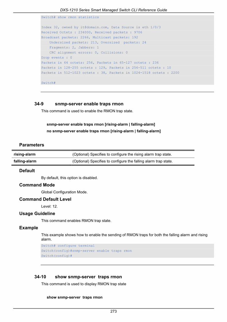
DXS-1210 Series Smart Managed Switch CLI Reference Guide
273
Switch# show rmon statistics
Index 32, owned by [email protected], Data Source is eth 1/0/3
Received Octets : 234000, Received packets : 9706
Broadcast packets: 2266, Multicast packets: 192
Undersized packets: 213, Oversized packets: 24
Fragments: 2, Jabbers: 1
CRC alignment errors: 0, Collisions: 0
Drop events : 0
Packets in 64 octets: 256, Packets in 65-127 octets : 236
Packets in 128-255 octets : 129, Packets in 256-511 octets : 10
Packets in 512-1023 octets : 38, Packets in 1024-1518 octets : 2200
Switch#
34-9 snmp-server enable traps rmon This command is used to enable the RMON trap state.
snmp-server enable traps rmon [rising-alarm | falling-alarm]
no snmp-server enable traps rmon [rising-alarm | falling-alarm]
Parameters
rising-alarm (Optional) Specifies to configure the rising alarm trap state.
falling-alarm (Optional) Specifies to configure the falling alarm trap state.
Default By default, this option is disabled.
Command Mode Global Configuration Mode.
Command Default Level Level: 12.
Usage Guideline This command enables RMON trap state.
Example This example shows how to enable the sending of RMON traps for both the falling alarm and rising alarm. Switch# configure terminal
Switch(config)#snmp-server enable traps rmon
Switch(config)#
34-10 show snmp-server traps rmon This command is used to display RMON trap state
show snmp-server traps rmon

DXS-1210 Series Smart Managed Switch CLI Reference Guide
274
Parameters None.
Default None.
Command Mode EXEC Mode or Any Configuration Mode.
Command Default Level Level: 1.
Usage Guideline To display RMON trap state.
Example This example shows how to display the RMON trap state. Switch# show snmp traps rmon
Rmon Trap State:
RMON Rising Alarm Trap: Enabled
RMON Falling Alarm Trap: Enabled
Switch#

DXS-1210 Series Smart Managed Switch CLI Reference Guide
275
35. Safeguard Engine Commands 35-1 cpu-protect safeguard
This command is used to enable or configure the Safeguard Engine. Use the no form of this command to disable the Safeguard Engine.
cpu-protect safeguard
no cpu-protect safeguard
Default By default, Safeguard Engine is disabled.
Command Mode Global Configuration Mode.
Command Default Level Level: 12.
Usage Guideline The Safeguard Engine can help the overall operability of the device by minimizing the workload of the Switch while the attack is ongoing, thus making it capable to forward essential packets over its network in a limited bandwidth.
Example This example shows how to enable the Safeguard Engine. Switch# configure terminal
Switch(config)#cpu-protect safeguard
Switch(config)#
35-2 show cpu-protect safeguard This command is used to display the settings and status of the Safeguard Engine.
show cpu-protect safeguard
Parameters None.
Default None.
Command Mode EXEC Mode or Any Configuration Mode.
Command Default Level Level: 1.
Usage Guideline This command is used to display the settings and status of the Safeguard Engine.
Example

DXS-1210 Series Smart Managed Switch CLI Reference Guide
276
This example shows how to display the settings and current status of the Safeguard Engine. Switch#show cpu-protect safeguard
Safeguard Engine State: Disabled
Switch#

DXS-1210 Series Smart Managed Switch CLI Reference Guide
277
36. Secure Sockets Layer (SSL) Commands 36-1 show ssl-service-policy
This command is used to display the SSL service policy.
show ssl-service-policy [POLICY-NAME]
Parameters
POLICY-NAME (Optional) Specifies the name of the SSL service policy.
Default None.
Command Mode Privileged EXEC Mode or Any Configuration Mode.
Command Default Level Level: 12.
Usage Guideline When the name of the SSL service policy is not specified, all SSL service policies will be displayed.
Example This example shows how to display all SSL service policies. Switch# show ssl-service-policy
SSL Policy Name : policy1
Enabled Cipher Suites:
RSA_WITH_RC4_128_MD5,
RSA_WITH_3DES_EDE_CBC_SHA,
RSA_EXPORT_WITH_RC4_40_MD5
Session Cache Timeout: 600
SSL Policy Name : policy2
Enabled Cipher Suites:
RSA_WITH_RC4_128_MD5,
RSA_WITH_3DES_EDE_CBC_SHA,
RSA_EXPORT_WITH_RC4_40_MD5
Session Cache Timeout: 1200
Switch#
36-2 ssl-service-policy This command is used to configure the SSL service policy.
ssl-service-policy POLICY-NAME [ciphersuite [rsa-null-md5] [rsa-null-sha][rsa-des-sha][rsa-3des-sha][dh-rsa-des-sha][dh-rsa-3des-sha][rsa-exp1024-des-sha][rsa-with-aes-128-cbc-sha][rsa-with-aes-256-cbc-sha][dhe-rsa-with-aes-128-cbc-sha][dhe-rsa-with-aes-256-cbc-sha] | session-cache-timeout TIME-OUT]
no ssl-service-policy POLICY-NAME [{ciphersuite [rsa-null-md5] [rsa-null-sha][rsa-des-sha][rsa-3des-sha][dh-rsa-des-sha][dh-rsa-3des-sha][rsa-exp1024-des-sha][rsa-with-aes-128-cbc-

DXS-1210 Series Smart Managed Switch CLI Reference Guide
278
sha][rsa-with-aes-256-cbc-sha][dhe-rsa-with-aes-128-cbc-sha][dhe-rsa-with-aes-256-cbc-sha]}|{session-cache-timeout}]
Parameters
POLICY-NAME Specifies the name of the SSL service policy.
ciphersuite (Optional) Specifies the cipher suites that should be used by the secure service when negotiating a connection with a remote peer. rsa-null-md5 Use RSA key exchange with null for message encryption and Message Digest 5(MD5) for message digest . rsa-null-sha Use RSA key exchange with null for message encryption and Secure Hash Algorithm(SHA) for message digest . rsa-des-sha Use RSA key exchange with des encryption for message encryption and SHA for message digest . rsa-3des-sha Use RSA key exchange with 3des encryption for message encryption and SHA for message digest . dh-rsa-des-sha Use DH and RSA key exchange with des encryption for message encryption and SHA key for message digest . dh-rsa-3des-sha Use DH and RSA key exchange with 3des encryption for message encryption and SHA key for message digest . rsa-exp1024-des-sha Use RSA key exchange with exp1024-des encryption for message encryption and SHA key for message digest . rsa-with-aes-128-cbc-sha Use RSA key exchange with aes 128-bit encryption and cbc encryption for message encryption and SHA key for message digest . rsa-with-aes-256-cbc-sha Use RSA key exchange with aes 256-bit encryption and cbc encryption for message encryption and SHA key for message digest . dhe-rsa-with-aes-128-cbc-sha Use DH and RSA key exchange with aes 128-bit encryption and cbc encryption for message encryption and SHA key for message digest . dhe-rsa-with-aes-256-cbc-sha Use DH and RSA key exchange with aes 256-bit encryption and cbc encryption for message encryption and SHA key for message digest .
session-cache-timeout TIME-OUT
(Optional) Specifies the timeout value in seconds for the information stored in the SSL session cache. The valid range is from 60 to 86400. When this parameter is not configured, the default session cache timeout is 600 seconds. In the no form of this command, the SSL session cache timeout will be reverted to the default value.
Default None.
Command Mode Global Configuration Mode.
Command Default Level Level: 15.
Usage Guideline This command is used to configure the SSL service policy.
Example This example shows how to configure the SSL service policy “ssl-server” which associates the “TP1” trust-point.

DXS-1210 Series Smart Managed Switch CLI Reference Guide
279
Switch# configure terminal
Switch(config)# ssl-service-policy ssl-server ciphersuite rsa-null-md5
Switch(config)#
36-3 show ssl-global-setting This command is used to to display the SSL global settings.
show ssl-global-setting
Parameters None.
Default None.
Command Mode EXEC Mode or Any Configuration Mode.
Command Default Level Level: 1.
Usage Guideline To display the SSL status.
Example This command is used to to display the SSL global settings. Switch# show ssl-global-setting
ssl server state: Disable
ssl service policy name:
Switch#
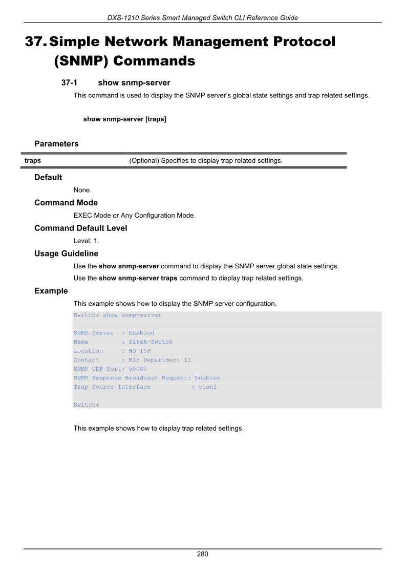
DXS-1210 Series Smart Managed Switch CLI Reference Guide
280
37. Simple Network Management Protocol (SNMP) Commands
37-1 show snmp-server This command is used to display the SNMP server’s global state settings and trap related settings.
show snmp-server [traps]
Parameters
traps (Optional) Specifies to display trap related settings.
Default None.
Command Mode EXEC Mode or Any Configuration Mode.
Command Default Level Level: 1.
Usage Guideline Use the show snmp-server command to display the SNMP server global state settings.
Use the show snmp-server traps command to display trap related settings.
Example This example shows how to display the SNMP server configuration. Switch# show snmp-server
SNMP Server : Enabled
Name : SiteA-Switch
Location : HQ 15F
Contact : MIS Department II
SNMP UDP Port: 50000
SNMP Response Broadcast Request: Enabled
Trap Source Interface : vlan1
Switch#
This example shows how to display trap related settings.

DXS-1210 Series Smart Managed Switch CLI Reference Guide
281
Switch# show snmp-server traps
Global Trap State : Enabled
Individual Trap State:
Authentication : Enabled
linkup : Enabled
linkdown : Enabled
coldstart : Enabled
warmstart : Disabled
Switch#
37-2 snmp-server This command is used to enable the SNMP agent. Use the no form of this command to disable the SNMP agent.
snmp-server
no snmp-server
Parameters None.
Default By default, this option is disabled.
Command Mode Global Configuration Mode.
Command Default Level Level: 12.
Usage Guideline The SNMP manager manages a SNMP agent by sending SNMP requests to agents and receiving SNMP responses and notifications from agents. The SNMP server on the agent must be enabled before the agent can be managed.
Example This example shows how to enable the SNMP server. Switch# configure terminal
Switch(config)#snmp-server
Switch(config)#
37-3 snmp-server contact This command is used to configure the system contact information for the device. Use the no form of this command to remove the setting.
snmp-server contact TEXT
no snmp-server contact

DXS-1210 Series Smart Managed Switch CLI Reference Guide
282
Parameters
contact TEXT Specifies a string for describing the system contact information. The maximum length is 255 characters The syntax is a general string that allows spaces.
Default None.
Command Mode Global Configuration Mode.
Command Default Level Level: 12.
Usage Guideline This command configures the system contact information for management of the device.
Example This example shows how to configure the system contact information with the string MIS Department II. Switch# configure terminal
Switch(config)#snmp-server contact “MIS Department II”
Switch(config)#
37-4 snmp-server enable traps This command is used to enable the sending of trap packets globally. Use the no form of this command to disable the sending of trap packets.
snmp-server enable traps
no snmp-server enable traps
Parameters None.
Default By default, this option is disabled.
Command Mode Global Configuration Mode.
Command Default Level Level: 12.
Usage Guideline This command enables the device to send the SNMP notification traps globally. To configure the router to send these SNMP notifications, enter the snmp-server enable traps command to enable the global setting.
Example This example shows how to enable the SNMP traps global sending state.

DXS-1210 Series Smart Managed Switch CLI Reference Guide
283
Switch# configure terminal
Switch(config)#snmp-server enable traps
Switch(config)#
37-5 snmp-server enable traps snmp This command is used to enable the sending of all or specific SNMP notifications. Use the no form of this commandto disable sending of all or specific SNMP notifications.
snmp-server enable traps snmp [authentication] [linkup] [linkdown] [coldstart] [warmstart]
no snmp-server enable traps snmp [authentication] [linkup] [linkdown] [coldstart] [warmstart]
Parameters
authentication (Optional) Specifies to control the sending of SNMP authentication failure notifications. An authenticationFailuretrap is generated when the device receives an SNMP message that is not properly authenticated. The authentication method depends on the version of SNMP being used. For SNMPv1 or SNMPv2c, authentication failure occurs if packets are formed with an incorrect community string. For SNMPv3, authentication failure occurs if packets are formed with an incorrect SHA/MD5 authentication key.
linkup (Optional) Specifies to control the sending of SNMP linkUp notifications. A linkup(3) trap is generated when the device recognizes that one of the communication links has come up.
linkdown (Optional) Specifies to control the sending of SNMP linkDown notifications. A linkDown(2) trap is generated when the device recognizes a failure in one of the communication links.
coldstart (Optional) Specifies to control the sending of SNMP coldStart notifications.
warmstart (Optional) Specifies to control the sending of SNMP warmStart notifications.
Default By default, this option is disabled.
Command Mode Global Configuration Mode.
Command Default Level Level: 12.
Usage Guideline This command controls the sending of SNMP standard notification traps. To enable the sending of notification traps, the global setting must be enabled too.
Example This example shows how to enable the switch to send all SNMP traps to the host 10.9.18.100 using the community string defined as public.

DXS-1210 Series Smart Managed Switch CLI Reference Guide
284
Switch# configure terminal
Switch(config)#snmp-server enable traps
Switch(config)# snmp-server enable traps snmp
Switch(config)# snmp-server host 10.9.18.100 version 2c public
Switch(config)#
This example shows how to enable the SNMP authentication traps. Switch# configure terminal
Switch(config)#snmp-server enable traps snmp authentication
Switch(config)#
37-6 snmp-server location This command is used to configure the system’s location information Use the no form of this command to remove the setting.
snmp-server location TEXT
no snmp-server location
Parameters
location TEXT Specifies the string that describes the system location information. The maximum length is 255 characters. The syntax is a general string that allows spaces.
Default None.
Command Mode Global Configuration Mode.
Command Default Level Level: 12.
Usage Guideline Use this command to configure the system’s location information on the Switch.
Example This example shows how to configure the system’s location information with the string “HQ 15F”. Switch# configure terminal
Switch(config)#snmp-server location “HQ 15F”
Switch(config)#
37-7 snmp-server name This command is used to configure the system’s name information. Use the no form of this command to remove the setting.
snmp-server name NAME
no snmp-server name
DXS-1210 Series Smart Managed Switch CLI Reference Guide
285
Parameters
NAME Specifies the string that describes the SNMP server name information. The maximum length is 64 characters. This name should start with a letter, and end with a letter or a number. Hyphens are allowed to be used in between the starting and ending characters. It is recommended not to configure the name longer than 10 characters.
Default By default, this name is “Switch”.
Command Mode Global Configuration Mode.
Command Default Level Level: 12.
Usage Guideline Use this command to configure the system’s name information on the Switch.
Example This example shows how to configure the system’s name to “SiteA-switch”. Switch#configure terminal
Switch(config)#snmp-server name SiteA-switch
SiteA-switch(config)#
37-8 snmp-server service-port This command is used to configure the SNMP UDP port number. Use the no form of this command to reset the UDP port number to default value.
snmp-server service-port PORT-NUMBER
no snmp-server service-port
Parameters
PORT-NUMBER Specifies the UDP port number. The range is from 0 to 65535. Some numbers may conflict with other protocols.
Default By default, this number is 161.
Command Mode Global Configuration Mode.
Command Default Level Level: 12.
Usage Guideline Use this command to configure the SNNP UDP port number on the Switch. The agent will listen to the SNMP request packets on the configured service UDP port number.
Example This example shows how to configure the SNMP UDP port number.

DXS-1210 Series Smart Managed Switch CLI Reference Guide
286
Switch# configure terminal
Switch(config)#snmp-server service-port 50000
Switch(config)#
37-9 snmp-server response broadcast-request This command is used to enable the server to response to broadcast SNMP GetRequest packets. Use the no form of this command to disable the response to broadcast SNMP GetRequest packets.
snmp-server response broadcast-request
no snmp-server response broadcast-request
Parameters None.
Default By default, this option is disabled.
Command Mode Global Configuration Mode.
Command Default Level Level: 12.
Usage Guideline This command is used to enable or disable the server to response to broadcast SNMP GetRequest packet. NMS tools would send broadcast SNMP GetRequest packets to discover networks device. To support this function, the response to the broadcast get request packet needs to be enabled.
Example This example shows how to enable the server to respond to the broadcast SNMP get request packet. Switch# configure terminal
Switch(config)#snmp-server response broadcast-request
Switch(config)#
37-10 show snmp This command is used to display the SNMP settings.
show snmp {community | host | view | group | engineID}
Parameters
community Specifies to display SNMP community information.
host Specifies to display SNMP trap recipient information.
view Specifies to display SNMP view information.
group Specifies to display SNMP group information.
engineID Specifies to display SNMP local engine ID information.
Default

DXS-1210 Series Smart Managed Switch CLI Reference Guide
287
None.
Command Mode Privileged EXEC Mode or Any Configuration Mode.
Command Default Level Level: 12.
Usage Guideline This command displays the SNMP information. When displaying SNMP community strings, the SNMPv1 or SNMPv2c user created will not be displayed.
Example This example shows how to display SNMP community information. Switch# show snmp community
Codes: ro - read only, rw – Read Write
Community access view
------------------ ---- ------------------------------------------------------------
System rw sales-divison checked with IP access control list: SalesDvision
public ro RD-division checked with IP access control list: HB5
Develop ro RD2
private rw Line2 checked with IP access control list: HQ
Total Entries: 4
Switch#
This example shows how to display the SNMP server host setting. Switch# show snmp host
Host IP Address : 10.20.30.40
SNMP Version : V1
Community Name : public
UDP Port : 50001
Host IP Address : 10.10.10.1
SNMP Version : V3 noauthnopriv
SNMPv3 User Name : user1
UDP Port : 50001
Host IPv6 Address: 1:12:123::100
SNMP Version : V3 noauthnopriv
SNMPv3 User Name : user2
UDP Port : 162
Total Entries: 3
Switch#
This example shows how to display the MIB view setting.

DXS-1210 Series Smart Managed Switch CLI Reference Guide
288
Switch# show snmp view
View Name Subtree View Type
-----------------------------------------------------------
restricted 1.3.6.1.2.1.1 Included
restricted 1.3.6.1.2.1.11 Included
restricted 1.3.6.1.6.3.10.2.1 Included
restricted 1.3.6.1.6.3.11.2.1 Included
restricted 1.3.6.1.6.3.15.1.1 Included
CommunityView 1 Included
CommunityView 1.3.6.1.6.3 Excluded
CommunityView 1.3.6.1.6.3.1 Included
Total Entries: 8
Switch#
This example shows how to display the SNMP group setting. Switch# show snmp group
GroupName: public SecurityModel: v1
ReadView : CommunityView WriteView :
NotifyView : CommunityView
IP access control list:
GroupName: public SecurityModel: v2c
ReadView : CommunityView WriteView :
NotifyView : CommunityView
IP access control list:
GroupName: initial SecurityModel: v3/noauth
ReadView : restricted WriteView :
NotifyView : restricted
IP access control list:
GroupName: private SecurityModel: v1
ReadView : CommunityView WriteView : CommunityView
NotifyView : CommunityView
IP access control list:
GroupName: private SecurityModel: v2c
ReadView : CommunityView WriteView : CommunityView
NotifyView : CommunityView
IP access control list:
Total Entries: 5
Switch#
This example shows how to display the SNMP engineID.

DXS-1210 Series Smart Managed Switch CLI Reference Guide
289
Switch# show snmp engineID
Local SNMP engineID: 00000009020000000C025808
Switch#
37-11 show snmp user This command is used to display information about the configured SNMP user.
show snmp user [USER-NAME]
Parameters
USER-NAME (Optional) Specifies the name of a specific user to display SNMP information.
Default None.
Command Mode Privileged EXEC Mode or Any Configuration Mode.
Command Default Level Level: 1.
Usage Guideline When the username argument is not specified, all configured users will be displayed. The community string created will not displayed by this command.
Example This example shows how SNMP users are displayed. Switch# show snmp user authuser
User name: authuser
Security Model: v2c
Group Name: VacmGroupName
IP access control list: HB5
User name: authuser
Security Model: v3 priv
Group Name: VacmGroupName
Authentication Protocol: MD5
Privacy Protocol: DES
Engine ID: 00000009020000000C025808
IP access control list:
Total Entries: 2
Switch#

DXS-1210 Series Smart Managed Switch CLI Reference Guide
290
37-12 snmp-server community This command is used to configure the community string to access the SNMP. Use the no form of this command to remove the community string,
snmp-server community [0 | 7] COMMUNITY-STRING [view VIEW-NAME] [ro | rw] [access IP-ACL-NAME]
no snmp-server community COMMUNITY-STRING
Parameters
0 COMMUNITY-STRING (Optional) Specifies the community string in the plain text form with a maximum of 32 alphanumeric characters. This is the default option.
7 COMMUNITY-STRING (Optional) Specifies the community string in the encrypted form.
view VIEW-NAME (Optional) Specifies a view name of a previously defined view. It defines the view accessible by the SNMP community.
ro (Optional) Specifies read-only access.
rw (Optional) Specifies read-write access.
access Set access control list for this community
IP-ACL-NAME (Optional) Specifies the name of the standard access list to control the user to use this community string to access to the SNMP agent. Specifies the valid user in the source address field of the access list entry.
Default
Community View Name Access right
private CommunityView Read/Write
public CommunityView Read Only
Command Mode Global Configuration Mode.
Command Default Level Level: 15.
Usage Guideline This command provides an easy way to create a community string for SNMPv1 and SNMPv2c management. When creating a community with the snmp-server community command, two SNMP group entries, one for SNMPv1 and one for SNMPv2c, which has the community name as their group names are created. If the view is not specified, it is permitted to access all objects.
Example This example shows how a MIB view “interfacesMibView” is created and a community string “comaccess” which can do read write access the interfacesMibView view is created. Switch# configure terminal
Switch(config)#snmp-server view interfacesMibView 1.3.6.1.2.1.2 included
Switch(config)# snmp-server community comaccess view interfacesMibView rw
Switch(config)#
DXS-1210 Series Smart Managed Switch CLI Reference Guide
291
37-13 snmp-server engineID local This command is used to specify the SNMP engine ID on the local device. Use the no form of this command to revert the SNMP engine ID to the default.
snmp-server engineID local ENGINEID-STRING
no snmp-server engineID local
Parameters
ENGINEID-STRING Specifies the engine ID string of a maximum of 24 characters.
Default None.
Command Mode Global Configuration Mode.
Command Default Level Level: 12.
Usage Guideline An SNMP engine ID is not displayed or stored in the running configuration. The SNMP engine ID is a unique string to identify the device. A string is generated by default. If you configure a string less than 24 characters, it will be filled with trailing zeros up to 24 characters.
Example This example shows how to configure the SNMP engine ID to 332200000000000000000000. Switch# configure terminal
Switch(config)#snmp-server engineID local 332200000000000000000000
Switch(config)#
37-14 snmp-server group This command is used to configure an SNMP group. Use the no form of this command to remove a SNMP group or remove a group from using a specific security model.
snmp-server group GROUP-NAME {v1 | v2c | v3 {auth | noauth | priv}} [read READ-VIEW] [write WRITE-VIEW] [notify NOTIFY-VIEW] [access IP-ACL-NAME]
no snmp-server group GROUP-NAME {v1 | v2c | v3 {auth | noauth | priv}}
Parameters
GROUP-NAME Specifies the group name of a maximum of 32 characters. The syntax is general string that does not allow space.
v1 Specifies that the group user can use the SNMPv1 security model.
v2c Specifies that the group user can use the SNMPv2c security model.
v3 Specifies that the group user can use the SNMPv3 security model.
auth Specifies to authenticate the packet but not encrypt it.
noauth Specifies not to authenticate and not to encrypt the packet.
priv Specifies to authenticate and encrypt the packet.

DXS-1210 Series Smart Managed Switch CLI Reference Guide
292
read READ-VIEW (Optional) Specifies a read-view that the group user can access.
write WRITE-VIEW (Optional) Specifies a write-view that the group user can access.
notify NOTIFY-VIEW (Optional) Specifies a write-view that the group user can access. The notify view describes the object that can be reported its status via trap packets to the group user.
access IP-ACL-NAME (Optional) Specifies the standard IP access control list (ACL) to associate with the group.
Default
Group Name
Version Security Level Read View Name
Write View Name
Notify View Name
Initial SNMPv3 noauth Restricted None Restricted
ReadGroup SNMPv1 noauth CommunityView None CommunityView
ReadGroup SNMPv2c noauth CommunityView None CommunityView
WriteGroup SNMPv1 noauth CommunityView CommunityView CommunityView
WriteGroup SNMPv2c noauth CommunityView CommunityView CommunityView
Command Mode Global Configuration Mode.
Command Default Level Level: 15.
Usage Guideline An SNMP group defines a user group by specifying the allowed security model, the read-view, the write-view, and the notification view. The security model defines that the group user is allowed to use the specified version of SNMP to access the SNMP agent,
The same group name can be created with security models SNMPv1, SNMPv2c, and SNMPv3 at the same time. For SNMPv3, it can be created for SNMPv3 auth and SNMPv3 priv at the same time.
To update the view profile for a group for a specific security mode, delete and create the group with the new view profile.
The read-view defines the MIB objects that the group user is allowed to read. If read-view is not specified, then Internet OID space 1.3.6.1 can be read.
The write-view defines the MIB objects that the group user is allowed to write. If write-view is not specified, then no MIB objects can be written.
The notification view defines the MIB objects that the system can report its status in the notification packets to the trap managers that are identified by the specified group user (act as community string). If notify-view is not specified, then no MIB objects can be reported.
Example This example shows how to create the SNMP server group “guestgroup” for SNMPv3 access and SNMPv2c. Switch# configure terminal
Switch(config)# snmp-server view interfacesMibView 1.3.6.1.2.1.2 included
Switch(config)# snmp-server group guestgroup v3 auth read interfacesMibView
Switch(config)# snmp-server group guestgroup v2c read CommunityView write CommunityView
Switch(config)#

DXS-1210 Series Smart Managed Switch CLI Reference Guide
293
37-15 snmp-server host This command is used to specify the recipient of the SNMP notification. Use the no form of this command to remove the recipient.
snmp-server host {IP-ADDRESS | IPV6-ADDRESS} [version {1 | 2c | 3 {auth | noauth | priv}}] COMMUNITY-STRING [port PORT-NUMBER]
no snmp-server host {IP-ADDRESS | IPV6-ADDRESS}
Parameters
IP-ADDRESS Specifies the IPv4 address of the SNMP notification host.
IPV6-ADDRESS Specifies the IPv6 address of the SNMP notification host.
version (Optional) Specifies the version of the SNMP used to send the traps. If not specified, the default is SNMPv1 1 - SNMPv1. 2c - SNMPv2c. 3 - SNMPv3.
auth Specifies to authenticate the packet but not to encrypt it.
noauth Specifies not to authenticate and to encrypt the packet.
priv Specifies to both authenticate and to encrypt the packet.
COMMUNITY-STRING Specifies the community string to be sent with the notification packet. If the version is 3, the community string is used as the username as defined in the snmp-sever user command.
PORT-NUMBER Specifies the UDP port number. The default trap UDP port number is 162. The range of UDP port numbers is from 0 to 65535. Some port numbers may conflict with other protocols.
Default By default, the version used is 1.
Command Mode Global Configuration Mode.
Command Default Level Level: 15.
Usage Guideline SNMP notifications are sent as trap packets. The user should create at least one recipient of a SNMP notification by using the snmp-server host command in order for the Switch to send the SNMP notifications. Specify the version of the notification packet for the created user. For SNMPv1 and SNMPv2c, the notification will be sent in the trap protocol data unit (PDU). For SNMPv3, the notification will be sent in the SNMPv2-TRAP-PDU with the SNMPv3 header.
When specifying to send the trap packets in SNMPv1 or SNMPv2c to a specific host, the specified community string acts as the community string in the trap packets.
When specifying to send the trap packets in SNMPv3 to a specific host, whether to do authentication and encryption in the sending of the packet should be specified. The specified community string acts as the username in the SNMPv3 packet. The user must be created first using the snmp-server user command or snmp-server user v3 command.
In the sending of the trap packet, the system will check the notification view associated with the specified user (or community name). If the binding variables to be sent with the trap packet are not in the notification view, the notification will not be sent to this host.
Example

DXS-1210 Series Smart Managed Switch CLI Reference Guide
294
This example shows how to configure the trap recipient 163.10.50.126 with version 1 with community string “comaccess”. Switch# configure terminal
Switch(config)#snmp-server community comaccess rw
Switch(config)# snmp-server host 163.10.50.126 version 1 comaccess
Switch(config)#
This example shows how to configure the trap recipient 163.10.50.126 with version 3 authentication security level and with the username “useraccess”. Switch# configure terminal
Switch(config)#snmp-server group groupaccess v3 auth read CommunityView write CommunityView
Switch(config)# snmp-server user useraccess groupaccess v3 auth md5 12345678
Switch(config)# snmp-server host 163.10.50.126 version 3 auth useraccess
Switch(config)#
This example shows how to configure the trap recipient 163.10.50.126 with version 1 with the community string “comaccess”. The UDP port number is configured to 50001. Switch# configure terminal
Switch(config)#snmp-server community comaccess rw
Switch(config)# snmp-server host 163.10.50.126 version 1 comaccess port 50001
Switch(config)#
37-16 snmp-server source-interface traps This command is used to specify the interface whose IP address will be used as the source address for sending the SNMP trap packet. Use the no form of this command to revert to the default setting.
snmp-server source-interface traps INTERFACE-ID
no snmp-server source-interface traps
Parameters
INTERFACE-ID Specifies the interface whose IP address will be used as the source address for sending the SNMP trap packet.
Default The IP address of the closest interface will be used.
Command Mode Global Configuration Mode.
Command Default Level Level: 15.
Usage Guideline Use this command to specify the interface whose IP address will be used as the source address for sending the SNMP trap packet.
Example This example shows how to configure VLAN100 as the sourcing interface for sending SNMP trap packets.

DXS-1210 Series Smart Managed Switch CLI Reference Guide
295
Switch# configure terminal
Switch(config)#snmp-server source-interface traps vlan 100
Switch(config)#
37-17 snmp-server user This command is used to create an SNMP user. Use the no form of this command to remove an SNMP user.
snmp-server user USER-NAME GROUP-NAME {v1 | v2c | v3 [encrypted] [auth {md5 | sha} AUTH-PASSWORD [priv PRIV-PASSWORD]]} [access IP-ACL-NAME]
no snmp-server user USER-NAME GROUP-NAME {v1 | v2c | v3}
Parameters
USER-NAME Specifies a username of a maximum of 32 characters. The syntax is general string that does not allow spaces.
GROUP-NAME Specifies the name of the group to which the user belongs. The syntax is general string that does not allow spaces.
v3 Specifies that the user uses the SNMPv3 security mode.
encrypted (Optional) Specifies that the following password is in encrypted format.
auth (Optional) Specifies the authentication level.
md5 Specifies to use HMAC-MD5-96 authentication.
sha Specifies to use HMAC-SHA-96 authentication.
AUTH-PASSWORD Specifies the authentication password in the plain-text form.This password is 8 to 16 octets for MD5 and 8 to 20 octets for SHA. If the keyword encrypted is specified, the length is 32 for MD5 and 40 for SHA. The format is a hexadecimal value.
PRIV-PASSWORD Specifies a privacy key used by DES. In the plain-text form, this password is 8 to 16 octets. If the keyword encrypted is specified, the length is fixed to 32 octets.
access IP-ACL-NAME (Optional) Specifies the standard IP access control list (ACL) to associate with the user.
Default By default, there is one user.
User Name: initial.
Group Name: initial.
Command Mode Global Configuration Mode.
Command Default Level Level: 15.
Usage Guideline To create a SMNP user, specify the security model that the user uses and the group that the user is created for. To create an SNMPv3 user, the password used for authentication and encryption needs to be specified.
An SNMP user is unable to be deleted if it has been associated with a SNMP server host.
Example

DXS-1210 Series Smart Managed Switch CLI Reference Guide
296
This example shows how the plain-text password is configured for the user “user1” in the SNMPv3 group public. Switch# configure terminal
Switch(config)#snmp-server user user1 public v3 auth md5 authpassword priv privpassword
Switch(config)#
This example shows how the MD5 digest string is used instead of the plain text password. Switch# configure terminal
Switch(config)#snmp-server user user1 public v3 encrypted auth md5 00112233445566778899AABBCCDDEEFF
Switch(config)#
37-18 snmp-server view This command is used to create or modify a view entry. Use the no form of this command to remove a specified SNMP view entry.
snmp-server view VIEW-NAME OID-TREE {included | excluded}
no snmp-server view VIEW-NAME
Parameters
VIEW-NAME Specifies the name of the view entry. The valid length is 1 to 32 characters. The syntax is general string that does not allow spaces.
OID-TREE Specifies the object identifier of the ASN.1 sub-tree to be included or excluded from the view. To identify the sub-tree, specify a text string consisting of numbers, such as 1.3.6.2.4, or a word, such as system. Use the asterisk (*) wildcard in a single sub-identifier to specify a sub-tree family.
included Specifies the sub-tree to be included in the SNMP view.
excluded Specifies the sub-tree to be excluded from the SNMP view.
Default
VIEW-NAME OID-TREE View Type
Restricted 1.3.6.1.2.1.1 Included
Restricted 1.3.6.1.2.1.11 Included
Restricted 1.3.6.1.6.3.10.2.1 Included
Restricted 1.3.6.1.6.3.11.2.1 Included
Restricted 1.3.6.1.6.3.15.1.1 Included
CommunityView 1 Included
CommunityView 1.3.6.1.6.3 Excluded
CommunityView 1.3.6.1.6.3.1 Included
Command Mode Global Configuration Mode.
Command Default Level Level: 15.

DXS-1210 Series Smart Managed Switch CLI Reference Guide
297
Usage Guideline Use this command to create a view of MIB objects.
Example This example shows how to create a MIB view called “interfacesMibView” and define an SNMP group “guestgroup” with “InterfaceMIBView” as the read view. Switch# configure terminal
Switch(config)#snmp-server view interfacesMibView 1.3.6.1.2.1.2 included
Switch(config)# snmp-server group guestgroup v3 auth read interfacesMibView
Switch(config)#

DXS-1210 Series Smart Managed Switch CLI Reference Guide
298
38. Spanning Tree Protocol (STP) Commands 38-1 clear spanning-tree detected-protocols
This command is used to restart the protocol migration.
clear spanning-tree detected-protocols {all | interface INTERFACE-ID}
Parameters
all Specifies to trigger the detection action for all ports.
interface INTERFACE-ID Specifies the port interface that will be triggered the detecting action.
Default None.
Command Mode Privileged EXEC Mode.
Command Default Level Level: 12.
Usage Guideline Using this command the port protocol migrating state machine will be forced to the SEND_RSTP state. This action can be used to test whether all legacy bridges on a given LAN have been removed. If there is no STP Bridge on the LAN, the port will be operated in the configured mode, either in the RSTP or MSTP mode. Otherwise, the port will be operated in the STP mode.
Example This example shows how to trigger the protocol migration event for all ports. Switch# clear spanning-tree detected-protocols all
Clear spanning-tree detected-protocols? (y/n) [n] y
Switch#
38-2 show spanning-tree This command is used to display the information of spanning tree protocol operation. This command is only for STP and RSTP.
show spanning-tree [interface [INTERFACE-ID [, | -]]
Parameters
interface INTERFACE-ID Specifies the interfaceID to display.
, (Optional) Specifies a series of interfaces, or separate a range of interfaces from a previous range. No space before and after the comma.
- (Optional) Specifies a range of interfaces. No space before and after the hyphen.

DXS-1210 Series Smart Managed Switch CLI Reference Guide
299
Default None.
Command Mode EXEC Mode or Any Configuration Mode.
Command Default Level Level: 1.
Usage Guideline Use this command to display the SpanningTree configuration for the single spanning tree when in the RSTP or STP-compatible mode.
Example This example shows how to display the spanning tree information when STP is enabled. Switch# show spanning-tree
Global Spanning Tree Status:
Spanning Tree: Enabled
STP New Root Trap: Disabled
STP Topology Change Trap: Disabled
Protocol Mode: RSTP
Priority: 32768
Bridge Max Age: 20
Bridge Hello Time: 2
Bridge Forward Time: 15
TX Hold Count: 6
Max Hops: 20
Topology Change Count: 0
Priority Link
Interface Role State Cost .Port# Type Edge
--------- ----- ----- ------ --------- ------ --------
eth1/0/3 designated forwarding 20000 128.3 p2p non-edge
eth1/0/5 backup blocking 200000 128.5 p2p non-edge
eth1/0/6 backup blocking 200000 128.6 shared non-edge
eth1/0/7 root forwarding 2000 128.7 P2p non-edge
Switch#
38-3 show spanning-tree configuration interface This command is used to display the information about STP interface related configuration.
show spanning-tree configuration interface [INTERFACE-ID [, | -]]
Parameters
interface INTERFACE-ID Specifies the interfaceID to display.
, (Optional) Specifies a series of interfaces, or separate a range of interfaces from a previous range. No space before and after the comma.
- (Optional) Specifies a range of interfaces. No space before and after the hyphen.

DXS-1210 Series Smart Managed Switch CLI Reference Guide
300
Default None.
Command Mode EXEC Mode or Any Configuration Mode.
Command Default Level Level: 1.
Usage Guideline Use this command to display Spanning Tree interface level configuration. The command can be used for all STP versions.
Example This example shows how to display spanning tree configuration information for interface eth1/0/1. Switch#show spanning-tree configuration interface ethernet 1/0/1
eth1/0/1
Spanning tree state : Enabled
Port path cost: 0
Port priority: 128
Port Identifier: 128.1
Link type: auto
Port fast: auto
Guard root: Disabled
TCN filter : Disabled
Bpdu forward: Disabled
Hello Time : 2
Switch#
38-4 snmp-server enable traps stp This command is used to enable the spanning tree to send SNMP notifications for STP. Use the no form of this command to disable the sending of notifications for STP.
snmp-server enable traps stp [new-root] [topology-chg]
no snmp-server enable traps stp [new-root] [topology-chg]
Parameters
new-root (Optional) Specifies the sending of STP new root notification.
topology-chg (Optional) Specifies the sending of STP topology change notification.
Default By default, this option is disabled.
Command Mode Global Configuration Mode.
Command Default Level Level: 12.
Usage Guideline

DXS-1210 Series Smart Managed Switch CLI Reference Guide
301
Use this command to enable the sending of notification traps. When using this command with no parameters specified, both STP notification types are enabled or disabled.
Example This example shows how to enable the router to send all STP traps to the host 10.9.18.100 using the community string defined as public. Switch# configure terminal
Switch(config)#snmp-server enable traps
Switch(config)# snmp-server enable traps stp
Switch(config)# snmp-server host 10.9.18.100 version 2c public
Switch(config)#
38-5 spanning-tree global state This command is used to enable or disable the STP’s global state. Use the no form to disable the STP’s global state.
spanning-tree global state {enable | disable}
no spanning-tree global state
Parameters
enable Specifies to enable the STP’s global state.
disable Specifies to disable the STP’s global state.
Default By default, this option is disabled.
Command Mode Global Configuration Mode.
Command Default Level Level: 12.
Usage Guideline Use this command in the global configuration mode to enable the global spanning-tree function.
Example This example shows how to enable the spanning-tree function. Switch# configure terminal
Switch(config)#spanning-tree global state enable
Switch(config)#
38-6 spanning-tree (timers) This command is used to configure the SpanningTree timer value. Use the no form of this command to revert to the default settings.
spanning-tree {hello-time SECONDS | forward-time SECONDS | max-age SECONDS}
no spanning-tree {hello-time | forward-time | max-age}

DXS-1210 Series Smart Managed Switch CLI Reference Guide
302
Parameters
hello-time SECONDS Specifies the interval that a designated port will wait between the periodic transmissionsof each configuration message. The range is from 1 to 2 seconds.
forward-time SECONDS Specifies the forward delay time used by STP to transition from the listening to the learning states and learning to forwarding states. The range is from 4 to 30 seconds.
max-age SECONDS Specifies the maximum message age of BPDU. The range is from 6 to 40 seconds.
Default The default value of the hello-time is 2 seconds.
The default value of the forward-time is 15 seconds.
The default value of the max-age is 20 seconds.
Command Mode Global Configuration Mode.
Command Default Level Level: 12.
Usage Guideline This command is used to configure the SpanningTree timer value.
Example This example shows how to configure the STP timers. Switch# configure terminal
Switch(config)#spanning-tree hello-time 1
Switch(config)# spanning-tree forward-time 16
Switch(config)# spanning-tree max-age 21
Switch(config)#
38-7 spanning-tree state This command is used to enable or disable the STP operation. Use the no form of this command to revert to the default setting.
spanning-tree state {enable | disable}
no spanning-tree state
Parameters
enable Specifies to enable STP for the configured interface.
disable Specifies to disable STP for the configured interface.
Default By default, this option is enabled.
Command Mode Interface Configuration Mode.
Command Default Level

DXS-1210 Series Smart Managed Switch CLI Reference Guide
303
Level: 12.
Usage Guideline When a port is spanning tree enabled, the spanning tree protocol engine will either send or process the spanning tree BPDU received by the port. The command should be used with caution to prevent bridging loops. The command does not take effect if the Layer 2 protocol tunnel is enabled for STP.
Example This example shows how to enable Spanning Tree on Ethernet interface eth1/0/1. Switch# configure terminal
Switch(config)#interface eth 1/0/1
Switch(config-if)# spanning-tree state enable
Switch(config-if)#
38-8 spanning-tree cost This command is used to configure the value of the port path-cost on the specified port. Use the no form of this command to revert to the auto-computed path cost.
spanning-tree cost COST
no spanning-tree cost
Parameters
COST Specifies the path cost for the port. The range is from 1 to 200000000.
Default The default path cost is computed from the interface’s bandwidth setting.
Command Mode Interface Configuration Mode.
Command Default Level Level: 12.
Usage Guideline In the RSTP or STP-compatible mode, the administrative path cost is used by the single spanning-tree to accumulate the path cost to reach the Root. In the MSTP mode, the administrative path cost is used by the CIST regional root to accumulate the path cost to reach the CIST root.
Example This example shows how to configure the port cost to 20000 for Ethernet interface eth1/0/7. Switch# configure terminal
Switch(config)#interface eth 1/0/7
Switch(config-if)# spanning-tree cost 20000
Switch(config-if)#
38-9 spanning-tree guard root This command is used to enable the root guard mode.Use the no form of this command to revert to the default setting.
spanning-tree guard root

DXS-1210 Series Smart Managed Switch CLI Reference Guide
304
no spanning-tree guard root
Parameters None.
Default By default, this option is disabled.
Command Mode Interface Configuration Mode.
Command Default Level Level: 12.
Usage Guideline BPDU guard prevents a port from becoming a root port. This feature is useful for the service provider to prevent external bridges to a core region of the network influencing the spanning tree active topology, possibly because those bridges are not under the full control of the administrator.
When a port is guarded from becoming a root port, the port will only play the role as a designated port. If the port receives the configuration BPDU with a higher priority, the port will change to the alternate port, which is in the blocking state. The received superior factor will not participate in the STP computation. The port will listen for BPDUs on the link. If the port times out the received superior BPDU, it will change to the designated port role.
When a port changes to the alternate port state, due to the root guard, a system message will be generated. This configuration will take effect for all the spanning-tree versions.
Example This example shows how to configure to prevent Ethernet interface eth1/0/1 from being a root port. Switch# configure terminal
Switch(config)#interface eth 1/0/1
Switch(config-if)# spanning-tree guard root
Switch(config-if)#
38-10 spanning-tree link-type This command is used to configure a link-type for a port. Use the no form of this command to revert to the default setting.
spanning-tree link-type {point-to-point | shared}
no spanning-tree link-type
Parameters
point-to-point Specifies that the port’s link type is point-to-point.
shared Specifies that the port’s link type is a shared media connection.
Default The link type is automatically derived from the duplex setting unless explicitly configuring the link type.
Command Mode Interface Configuration Mode.
Command Default Level Level: 12.
DXS-1210 Series Smart Managed Switch CLI Reference Guide
305
Usage Guideline A full-duplex port is considered to have a point-to-point connection; on the opposite, a half-duplex port is considered to have a shared connection .The port can’t transit into forwarding state rapidly by setting link type to shared-media. Hence, auto-determined of link-type by the STP module is recommended.
This configuration will take effect for all the spanning-tree modes.
Example This example shows how to configure the link type to point-to-point for port eth1/0/7. Switch# configure terminal
Switch(config)#interface eth 1/0/7
Switch(config-if)# spanning-tree link-type point-to-point
Switch(config-if)#
38-11 spanning-tree mode This command is used to configure the STP mode. Use the no form of this command to revert to the default setting.
spanning-tree mode {mstp | rstp |stp}
no spanning-tree mode
Parameters
mstp Specifies the Multiple Spanning Tree Protocol (MSTP).
rstp Specifies the Rapid Spanning Tree Protocol (RSTP).
stp Specifies the Spanning Tree Protocol (IEEE 802.1D Compatible)
Default By default, this mode isrstp.
Command Mode Global Configuration Mode.
Command Default Level Level: 12.
Usage Guideline If the mode is configured as STP or RSTP, all currently running MSTP instances will be cancelled automatically. If the newly configured mode is changed from the previous one, the spanning-tree state machine will restart again, therefore all of the stable spanning-tree port states will transit into discarding states.
Example This example shows how to configure the running version of the STP module to RSTP. Switch# configure terminal
Switch(config)#spanning-tree mode rstp
Switch(config)#

DXS-1210 Series Smart Managed Switch CLI Reference Guide
306
38-12 spanning-tree portfast This command is used to specify the port’s fast mode. Use the no form of this command to revert to the default setting.
spanning-tree portfast {disable | edge| network}
no spanning-tree portfast
Parameters
disable Specifies to set the port to the port fast disabled mode.
edge Specifies to set the port to the port fast edge mode.
network Specifies to set the port to the port fast network mode.
Default By default, this option is edge.
Command Mode Interface Configuration Mode.
Command Default Level Level: 12.
Usage Guideline A port can be in one of the following three port fast modes:
• Edge mode - The port will directly change to the spanning-tree forwarding state when a link-up occurs without waiting for the forward-time delay. If the interface receives a BPDU later, its operation state changes to the non-port-fast state.
• Disable mode - The port will always be in the non-port-fast state. It will always wait for the forward-time delay to change to forwarding state.
• Network mode - The port will remain in the non-port-fast state for three seconds. The port will change to the port-fast state if no BPDU is received and changes to the forwarding state. If the port received the BPDU later, it will change to the non-port-fast state
This command should be used with caution. Otherwise, an accidental topology loop and data-packet loop may be generated and disrupt the network operation.
Example This example shows how to configure port eth1/0/7 to the port-fast edge mode. Switch# configure terminal
Switch(config)#interface eth 1/0/7
Switch(config-if)# spanning-tree portfast edge
Switch(config-if)#
38-13 spanning-tree port-priority This command is used to configure the value of the STP port priority on the specified port. It is only used for RSTP and STP versions. Use the no form of this command to revert to the default setting.
spanning-tree port-priority PRIORITY
no spanning-tree port-priority
Parameters

DXS-1210 Series Smart Managed Switch CLI Reference Guide
307
PRIORITY Specifies the port priority.Valid values are from 0 to 240.
Default By default, this value is 128.
Command Mode Interface Configuration Mode.
Command Default Level Level: 12.
Usage Guideline The port priority and the port number together form the Port Identifier. It will be used in the computation of the role of the port. This parameter is used only in the RSTP and STP-compatible mode. A smaller number represents a better priority.
Example This example shows how to configure the port priority to 0 for port eth1/0/7. Switch# configure terminal
Switch(config)#interface eth 1/0/7
Switch(config-if)# spanning-tree port-priority 0
Switch(config-if)#
38-14 spanning-tree priority This command is used to configure the bridge priority. It is only used for RSTP and STP versions. Use the no form of this command to restore to the default setting.
spanning-tree priority PRIORITY
no spanning-tree priority
Parameters
PRIORITY Specifies that the bridge priority and bridge MAC address together forms the Spanning-Tree Bridge-ID, which is an important factor in the Spanning-Tree topology. The range is from 0 to 61440.
Default By default, this value is 32768.
Command Mode Global Configuration Mode.
Command Default Level Level: 12.
Usage Guideline The bridge priority value is one of the two parameters used to select the Root Bridge. The other parameter is system’s MAC address. The bridge’s priority value must be divisible by 4096 and a smaller number represents a better priority.
This configuration will take effect on STP version and RSTP mode. In the MSTP mode, use the command spanning-tree mst priority to configure the priority for an MSTP instance.
Example This example shows how to configure the STP bridge priority value to 4096.

DXS-1210 Series Smart Managed Switch CLI Reference Guide
308
Switch# configure terminal
Switch(config)#spanning-tree priority 4096
Switch(config)#
38-15 spanning-tree tcnfilter This command is used to enable Topology Change Notification (TCN) filtering at the specific interface. Use the no form of this command to disable TCN filtering.
spanning-tree tcnfilter
no spanning-tree tcnfilter
Parameters None.
Default By default, this option is disabled.
Command Mode Interface Configuration Mode.
Command Default Level Level: 12.
Usage Guideline Enabling TC filtering on a port is useful for an ISP to prevent the external bridge to a core region of the network, causing address flushing in that region, possibly because those bridges are not under the full control of the administrator.
When a port is set to the TCN filter mode, the TC event received by the port will be ignored. This configuration will take effect for all the spanning-tree modes.
Example This example shows how to configure TCN filtering on port eth1/0/7. Switch# configure terminal
Switch(config)#interface eth 1/0/7
Switch(config-if)# spanning-tree tcnfilter
Switch(config-if)#
38-16 spanning-tree tx-hold-count This command is used to limit the maximum number of BPDUs that can be sent before pausing for one second. Use the no form of this command to revert to the default setting.
spanning-tree tx-hold-count VALUE
no spanning-tree tx- hold-count
Parameters
VALUE Specifies the maximum number of BPDUs that can be sent before pausing for one second. The range is from 1 to 10.

DXS-1210 Series Smart Managed Switch CLI Reference Guide
309
Default By default, this value is 6.
Command Mode Global Configuration Mode.
Command Default Level Level: 12.
Usage Guideline This command specifies the number of hold BPDUs to transmit. The transmission of BPDUs on a port is controlled by a counter. The counter is incremented on every BPDU transmission and decremented once a second. The transmissions are paused for one second if the counter reaches the transmit hold count.
Example This example shows how to configure the transmitholdcount value to 5. Switch# configure terminal
Switch(config)#spanning-tree tx-hold-count 5
Switch(config)#
38-17 spanning-tree forward-bpdu This command is used to enable the forwarding of the spanningtree BPDU. Use the no form of this command to disable the forwarding of the spanningtree BPDU.
spanning-tree forward-bpdu
no spanning-tree forward-bpdu
Parameters None.
Default By default, this option is disabled.
Command Mode Interface Configuration Mode.
Command Default Level Level: 12.
Usage Guideline If enabled, the received STP BPDU will be forwarded to all VLAN member ports in the untagged form. The command does not take effect if the Layer 2 protocol tunnel is enabled for STP.
Example This example shows how to enable the forwarding of STP BPDUs. Switch# configure terminal
Switch(config)#interface eth 1/0/1
Switch(config-if)# spanning-tree forward-bpdu
Switch(config-if)#

DXS-1210 Series Smart Managed Switch CLI Reference Guide
310
39. Storm Control Commands 39-1 snmp-server enable traps storm-control
This command is used enable or control the command to enable sending SNMP notifications for storm control. Use the no form of this command to disable sending SNMP notifications.
snmp-server enable traps storm-control [storm-occur] [ storm-clear]
no snmp-server enable traps storm-control [storm-occur] [ storm-clear]
Parameters
storm-occur (Optional) Specifies to send a notification when a storm event is detected.
storm-clear (Optional) Specifies to send a notification when a storm event is cleared.
Default By default, this option is disabled.
Command Mode Global Configuration Mode.
Command Default Level Level: 12.
Usage Guideline This command with keyword storm-occur and storm-clear enables or disables the notifications for storm control module. If no optional keywords is specified, both storm-occur and storm-clear notifications are enabled or disabled. If you enter the command with a keyword, only the specified notification type is enabled or disabled.
Example This example shows how to enable sending trap for storm control for both storm occurred and cleared. Switch#configure terminal
Switch(config)#snmp-server enable traps storm-control
Switch(config)#
39-2 storm-control This command is used to configure the device to protect the device from broadcast, multicast, and DA unknown packet storm attacks. Use the no form of this command to restore the function to its default settings.
storm-control {{broadcast | multicast | unicast} level {pps PPS-RISE [PPS-LOW] | kbps KBPS-RISE [KBPS-LOW] } | action {shutdown | drop | none}}
no storm-control {broadcast | multicast | unicast | action}
Parameters
broadcast Specifies to set the broadcast rate limit.
multicast Specifies to set the multicast rate limit.

DXS-1210 Series Smart Managed Switch CLI Reference Guide
311
unicast Specifies to set the unicast rate limit. When the action is configured as the shutdown mode, the unicast refers to both known and unknown unicast packets; that is, if the known and unknown unicast packets hit the specified threshold, the port will be shutdown. Otherwise, unicast refers to unknown unicast packets.
level pps PPS-RISE [PPS-LOW]
Specifies the threshold value in packets count per second. The range is from 0 to 2147483647. If the low PPS value is not specified, the default value is 80% of the specified risen PPS.
level kbps KBPS-RISE [KBPS-LOW]
Specifies the threshold value as a rate of bits per second at which traffic is received on the port. The range is from 0 to 2147483647. If the low KBPS is not specified, the default value is 80% of the specified risen KBPS.
action shutdown Specifies to shutdown the port when the value specified for rise threshold is reached.
action drop Specifies to discards packets that exceed the risen threshold.
action none Specifies not to filter the storm packets.
Default By default, the broadcast, multicast, and unicast (DLF) storm controls are disabled.
The default action taken when a storm occurs is to drop storm packets.
Command Mode Interface Configuration Mode.
Command Default Level Level: 12.
Usage Guideline Use the storm control function to protect the network from the storm of broadcast packets, multicast packets, or unknown DA flooding packets. Enter the storm-control command to enable storm control for a specific traffic type on the interface.
There are two ways to recover an error disabled port.
• The user can use the errdisable recovery cause command to enable the automatic recovery of ports that were error disabled by storm control.
• The user can manually recover the port by entering the shutdown command, followed by the no shutdown command for the port.
There is only one meter mode (percentage, kbps or pps) that can take effect on an interface. On an interface, if the later specified meter mode option is different from the previous mode, the previous configured storms will reset to their default states (disabled in this specification).
Due to hardware limitations, when the meter mode is percentage or kbps:
• The action cannot be specified to the shutdown mode.
• There are no traps and logs for the drop and none modes.
This feature is unable to give the precise suppression level of the total bandwidth in percentage (0 to 100) of a specific port interface. The current calculation formula assumes that the packet size is 64 bytes.
Example This example shows how to enable broadcast storm control on eth1/0/1. It sets the threshold of eth3/0/1 to 500 packets per second with the shutdown action. Switch# configure terminal
Switch(config)#interface eth1/0/1
Switch(config-if)# storm-control broadcast level pps 500
Switch(config-if)# storm-control action shutdown

DXS-1210 Series Smart Managed Switch CLI Reference Guide
312
39-3 storm-control polling This command is used to configure the polling interval of received packet counts. Use the no form of this command to restore to its default settings.
storm-control polling {interval SECONDS | retries {NUMBER | infinite}}
no storm-control polling {interval | retries}
Parameters
interval SECONDS Specifies the polling interval of received packet counts. This value must be between 1 and 300 seconds.
retries NUMBER Specifies the retry count. If the action is configured to the shutdown mode and a storm continues as long as the interval times retries values set, the port will enter the error disabled state. This value must be between 0 and 360. 0 means that a shutdown mode port will directly enter the error disabled state when a storm is detected. Infinite means that a shutdown mode port will never enter the error disabled state even if a storm was detected.
Default The default polling interval is 5 seconds.
The default retries count value is 3.
Command Mode Global Configuration Mode.
Command Default Level Level: 12.
Usage Guideline Use this to specify the sample interval of received packet counts.
Example This example shows how to specify the polling interval as 15 seconds. Switch# configure terminal
Switch(config)#storm-control polling interval 15
Switch(config)#
39-4 show storm-control This command is used to display the current storm control settings.
show storm-control interface INTERFACE-ID [, | -] [broadcast | multicast | unicast]
Parameters
INTERFACE-ID Specifies the port’s interface ID.
, (Optional)Specifies a series of interfaces, or separate a range of interfaces from a previous range. No space is allowed before and after the comma.
- (Optional)Specifies a range of interfaces. No space is allowed before

DXS-1210 Series Smart Managed Switch CLI Reference Guide
313
and after the hyphen.
broadcast Specifies to display the current broadcast storm setting.
multicast Specifies to display the current multicast storm setting.
unicast Specifies to display the current unicast(DLF) storm setting.
Default None.
Command Mode EXEC Mode or Any Configuration Mode.
Command Default Level Level: 1.
Usage Guideline If the interface ID is not specified, all interfaces configurations will be displayed.
If the packet type is not specified, all types of storm control settings will be displayed.
Example This example shows how to displaythe current broadcast storm control settings. Switch# show storm-control interface range ethernet 1/0/1-1/0/6 broadcast
Polling Interval : 15 sec Shutdown Retries : Infinite
Trap : Disabled
Interface Storm Action Threshold Current State
-----------------------------------------------------------
eth1/0/1 Broadcast Drop 500/300 pps 200 pps Forwarding
eth1/0/2 Broadcast Drop 80/64 % 20 % Forwarding
eth1/0/3 Broadcast Drop 80/64 % 70 % Dropped
eth1/0/4 Broadcast Shutdown 60/50 % 20 % Forwarding
eth1/0/5 Broadcast None 60000/50000 kbps 2000 kbps Forwarding
eth1/0/6 Broadcast None - - Inactive
Total Entries: 6
Switch#
This example shows how to display all interface settings for the range from port 1/0/1 to port 1/0/2. Switch# show storm-control interface eth1/0/1-2
Polling Interval : 15 sec Shutdown Retries : Infinite
Trap : Disabled
Interface Storm Action Threshold Current State
---------------------- --------------------------------------------
eth1/0/1 Broadcast Drop 80/64 % 50% Forwarding
eth1/0/1 Multicast Drop 80/64 % 50% Forwarding
eth1/0/1 Unicast Drop 80/64 % 50% Forwarding
eth1/0/2 Broadcast Shutdown 500/300 pps - Error Disabled
eth1/0/2 Multicast Shutdown 500/300 pps - Error Disabled
eth1/0/2 Unicast Shutdown 500/300 pps - Error Disabled
Total Entries: 6
Switch#

DXS-1210 Series Smart Managed Switch CLI Reference Guide
314
Display Parameters
Interface The interface ID.
Action The configured action, the possible actions are: Drop, Shutdown, None.
Threshold The configured threshold.
Current The actual traffic rate which is currently flowing though the interface. Its unit may be percentage, kbps, PPS based on the configured meter mode. Because hardware can only counts by PPS, this value of this filed may be a rough value for percentage and kbps.
State The current state of storm control on a given interface for a given traffic type. The possible states are: Forwarding: No storm event has been detected. Dropped: A storm event has occurred and the storm traffic exceeding the threshold is dropped. Error Disabled: The port is disabled due to a storm. Link Down: The port is physically linked down. Inactive: Indicates that storm control is not enabled for the given traffic type.
39-5 show snmp-server traps storm-control This command is used to Display storm control trap state.
show snmp-server traps storm-control
Parameters None.
Default None.
Command Mode EXEC Mode or Any Configuration Mode.
Command Default Level Level: 1.
Usage Guideline This command is used to Display storm control trap state.
Example This command is used to Display storm control trap state. Switch# show snmp-server traps storm-control
storm occur : Disabled
storm clear : Disabled
Switch#

DXS-1210 Series Smart Managed Switch CLI Reference Guide
315
40. Surveillance VLAN Commands 40-1 surveillance vlan
This command is used toenable the global surveillance VLAN state and configure the surveillance VLAN. Use the no form of this command to disable the surveillance VLAN state.
surveillance vlan VLAN-ID
no surveillance vlan
Parameters
VLAN-ID Specifies the ID of the surveillance VLAN. The range is from 2 to 4094.
Default By default, this option is disabled.
Command Mode Global Configuration Mode.
Command Default Level Level: 12.
Usage Guideline Use this command to enable the global surveillance VLAN function and to specify the surveillance VLAN on the Switch. Each switch can only have one Surveillance VLAN.
Both the surveillance vlan command in Global Configuration Mode and the surveillance vlan enable command in Interface Configuration Mode need to be enabled for a port to start the surveillance VLAN function.
When the surveillance VLAN is enabled for a port, the port will be automatically learned as surveillance VLAN untagged member, the received untagged surveillance packets will be forwarded to the surveillance VLAN. The received packets are determined as surveillance packets if the source MAC addresses of packets comply with the organizationally unique identifier (OUI) addresses configured by the surveillance vlan mac-address command.
A VLAN needs to be created before assigning the VLAN as the surveillance VLAN.
If the surveillance VLAN is configured, this VLAN cannot be removed using the no vlan command.
Example This example shows how to enable the surveillance VLAN function and configure VLAN 1001 as a Surveillance VLAN. Switch# configure terminal
Switch(config)# surveillance vlan 1001
Switch(config)#
40-2 surveillance vlan aging This command is used to configure the aging time for aging out the surveillance VLAN dynamic member ports. Use the no form of this command to reset the aging time to the default setting.
surveillance vlan aging MINUTES
no surveillance vlan aging

DXS-1210 Series Smart Managed Switch CLI Reference Guide
316
Parameters
MINUTES Specifies the aging time of surveillance VLAN. The range is from 1 to 65535 minutes.
Default By default, this aging time is 720 minutes.
Command Mode Global Configuration Mode.
Command Default Level Level: 12.
Usage Guideline Use this command to configure the aging time for aging out the surveillance device and the surveillance VLAN automatically learned member ports.
When the last surveillance device connected to the port stops sending traffic, and the MAC address of this surveillance device is aged out, the surveillance VLAN aging timer will be started. The port will be removed from the surveillance VLAN after expiration of surveillance VLAN aging timer.
If the surveillance traffic resumes during the aging time, the aging timer will be cancelled.
Example This example shows how to configure the aging time of surveillance VLAN to 30 minutes. Switch# configure terminal
Switch(config)#surveillance vlan aging 30
Switch(config)#
40-3 surveillance vlan enable This command is used to enable the surveillance VLAN state of ports. Use the no form of this command to disable the surveillance VLAN state of ports.
surveillance vlan enable
no surveillance vlan enable
Parameters None.
Default By default, this option is disabled.
Command Mode Interface Configuration Mode.
Command Default Level Level: 12.
Usage Guideline The command is available for physical port and port-channel interface configuration.
The command takes effect for access ports or hybrid ports.
Use this command to enable the surveillance VLAN function for ports.

DXS-1210 Series Smart Managed Switch CLI Reference Guide
317
Both the surveillance vlan command in Global Configuration Mode and the surveillance vlan enable command in Interface Configuration Mode need to be enabled for a port to start the surveillance VLAN function.
When surveillance VLAN is enabled for a port, the port will be automatically learned as surveillance VLAN untagged member, the received untagged surveillance packets will be forwarded to surveillance VLAN. The received packets are determined as surveillance packets if the source MAC addresses of packets comply with the organizationally unique identifier (OUI) addresses configured by the surveillance vlan mac-address command.
Example This example shows how to enable surveillance VLAN function on physical port eth1/0/1. Switch# configure terminal
Switch(config)#interface eth 1/0/1
Switch(config-if)#surveillance vlan enable
Switch(config-if)#
40-4 surveillance vlan mac-address This command is used to add the user-defined surveillance device OUI. Use the no form of this command to delete the user-defined surveillance device OUI.
surveillance vlan mac-address MAC-ADDRESS MASK [component-type {vms | vms-client | video-encoder | network-storage | other} description TEXT]
no surveillance vlan mac-address MAC-ADDRESS MASK
Parameters
MAC-ADDRESS Specifies the OUI MAC address.
MASK Specifies the OUI MAC address matching bitmask.
component-type (Optional) Specifies surveillance components that could be auto-detected by surveillance VLAN.
vms (Optional) Specifies thesurveillance components type as Video Management Server (VMS).
vms-client (Optional) Specifies the surveillance components type as VMS client.
video-encoder (Optional) Specifies the surveillance components type as Video Encoder.
network-storage (Optional) Specifies the surveillance components type as Network Storage.
other (Optional) Specifies the surveillance components type as other IP Surveillance Devices.
description TEXT (Optional) Specifies the description for the user-defined OUI with a maximum of 32 characters.
Default
OUI Address Mask Component Type Description
28-10-7B-00-00-00 FF-FF-FF-E0-00-00 D-Link Device IP Surveillance Device
28-10-7B-20-00-00 FF-FF-FF-F0-00-00 D-Link Device IP Surveillance Device
B0-C5-54-00-00-00 FF-FF-FF-80-00-00 D-Link Device IP Surveillance Device
F0-7D-68-00-00-00 FF-FF-FF-F0-00-00 D-Link Device IP Surveillance Device

DXS-1210 Series Smart Managed Switch CLI Reference Guide
318
Command Mode Global Configuration Mode.
Command Default Level Level: 12.
Usage Guideline Use this command to add user-defined OUI(s) for the surveillance VLAN. The OUI for surveillance VLAN are used to identify the surveillance traffic by the surveillance VLAN function.
If the source MAC addresses of the received packet matches any of the OUI pattern, the received packet is determined as a surveillance packet.
The user-defined OUI cannot be the same as the default OUI.
The default OUI cannot be deleted.
Example This example shows how to add a user-defined OUI for surveillance devices. Switch# configure terminal
Switch(config)# surveillance vlan mac-address 00-01-02-03-00-00 FF-FF-FF-FF-00-00 component-type vms description user1
Switch(config)#
40-5 surveillance vlan qos This command is used to configure the CoS priority for the incoming surveillance VLAN traffic. Use the no form of this command to revert to the default settings.
surveillance vlan qos COS-VALUE
no surveillance vlan qos
Parameters
COS-VALUE Specifies the priority of surveillance VLAN. The available value is from 0 to 7.
Default The default value 5.
Command Mode Global Configuration Mode.
Command Default Level Level: 12.
Usage Guideline The surveillance packets arriving at the surveillance VLAN enabled port are marked to the COS specified by the command.
The remarking of COS allows the surveillance VLAN traffic to be distinguished from data traffic in quality of service.
Example This example shows how to configure the priority of the surveillance VLAN to be 7.

DXS-1210 Series Smart Managed Switch CLI Reference Guide
319
Switch# configure terminal
Switch(config)# surveillance vlan qos 7
Switch(config)#
40-6 show surveillance vlan This command is used to display the surveillance VLAN configurations.
show surveillance vlan [ interface [ INTERFACE-ID [, | -] ] ]
show surveillance vlan device [ interface [ INTERFACE-ID [, | -] ] ]
Parameters
device Specifies to display the learned surveillance devices information
interface (Optional) Specifies to display surveillance VLAN information of ports.
INTERFACE-ID (Optional) Specifies the port to be displayed.
, (Optional) Specifies a series of interfaces, or separate a range of interfaces from a previous range. No space is allowed before and after the comma.
- (Optional) Specifies a range of interfaces. No space is allowed before and after the hyphen.
Default None.
Command Mode EXEC Mode or Any Configuration Mode.
Command Default Level Level: 1.
Usage Guideline Use this command to display the surveillance VLAN configurations.
The show surveillance vlancommand is used to display the surveillance VLAN global configurations.
The show surveillance vlan interface command is used to display the surveillance vlan configurations on the interfaces.
The show surveillance vlan device command is used to display the surveillance device discovered by its OUI.
Example This example shows how to displays the surveillance VLAN global settings.

DXS-1210 Series Smart Managed Switch CLI Reference Guide
320
Switch# show surveillance vlan
Surveillance VLAN State : Enabled
Surveillance VLAN ID : 100
Surveillance VLAN CoS : 5
Aging Time : 30 minutes
Surveillance VLAN OUI :
OUI Address Mask Component Type Description
----------------- ----------------- --------------- --------------
28-10-7B-00-00-00 FF-FF-FF-E0-00-00 D-Link Device IP Surveillance Device
28-10-7B-20-00-00 FF-FF-FF-F0-00-00 D-Link Device IP Surveillance Device
B0-C5-54-00-00-00 FF-FF-FF-80-00-00 D-Link Device IP Surveillance Device
F0-7D-68-00-00-00 FF-FF-FF-F0-00-00 D-Link Device IP Surveillance Device
Total OUI: 4
Switch#

DXS-1210 Series Smart Managed Switch CLI Reference Guide
321
41. Switch Port Commands 41-1 duplex
This command is used to configure the physical port interface’s duplex setting. Use the no form of command to revert to the default setting.
duplex {full | auto}
no duplex
Parameters
full Specifies that the port operates in the full-duplex mode.
auto Specifies that the port’s duplex mode will be determined by auto-negotiation.
Default The duplex mode will be set as auto for 1000BASE-T interfaces.
Command Mode Interface Configuration Mode.
Command Default Level Level: 12.
Usage Guideline Auto-negotiation will be enabled if either the speed parameter is set to auto or the duplex parameter is set to auto. If the speed parameter is set to auto and the duplex parameter is set to the fixed mode, only the speed will be negotiated. The advertised capability will be configured to the duplex mode combined with all the possible speeds. If the speed is to set to a fixed speed and duplex is set to auto, only the duplex mode is negotiated. The advertised capability will be both full and half-duplex mode combined with the configured speeds.
Example This example shows how to configure the interface eth1/0/1 to operate at a forced speed of 100Mbits and specifies that the duplex mode should be set to auto-negotiated. Switch# configure terminal
Switch(config)#interface eth 1/0/1
Switch(config-if)# speed 100
Switch(config-if)# duplex auto
Switch(config-if)#
41-2 flowcontrol This command is used to configure the flow control capability of the port interface. Use the no form of command to revert to the default setting.
flowcontrol {on | off}
no flowcontrol
Parameters

DXS-1210 Series Smart Managed Switch CLI Reference Guide
322
on Specifies to enable a port to send PAUSE frames or process PAUSE frames from remote ports.
off Specifies to disable the ability for a port to send or receive PAUSE frames.
Default By default, this option is disabled.
Command Mode Interface Configuration Mode.
Command Default Level Level: 12.
Usage Guideline This command can only assure that the flow control capability has been configured in the Switch software and not guarantee the actual hardware operation. The actual hardware operation may be different to the settings that have been configured on the Switch because the flow control capability is determined by both the local port/device and the device connected at the other end of the link, not just by the local device.
If the speed is set to the forced mode, the final flow control setting will be determined by the configured flow control setting. If the speed is set to the auto mode, the final flow control setting will be based on the negotiated result between the local side setting and the partner side setting. The configured flow control setting here is the local side setting.
Example This example shows how to enable the flow control on interface eth1/0/1. Switch# configure terminal
Switch(config)#interface eth 1/0/1
Switch(config-if)# flowcontrol on
Switch(config-if)#
41-3 speed This command is used to configure the physical port interface’s speed settings. Use the no form of command to revert to the default setting.
speed { 100 | 1000 | 10giga | auto [SPEED-LIST]}
no speed
Parameters
100 Specifies to force the speed to 100 Mbps.
1000 Specifies that for copper ports, it forces the speed to 1000 Mbps and the user must manually set that the port operates as master or slave. Specifies that for fiber ports (1000BASE-SX/LX), the port will disable the auto-negotiation.
10giga Specifies to force the speed to 10Gbps.
auto Specifies that for copper ports, it specifies to determine the speed and flow control via auto-negotiation with its link partner. Specifies that for fiber ports (1000BASE-SX/LX), it enables the auto-negotiation option. Auto-negotiation will start to negotiate the clock and flow control with its link partner.

DXS-1210 Series Smart Managed Switch CLI Reference Guide
323
SPEED-LIST (Optional) Specifies a list of speeds that the Switch will only auto-negotiate to. The speed can be 100,1000, and/or 10giga. Use a comma(,) to separate multiple speeds. If the speed list is not specified, all speed will be advertised.
Default The speed will be set as auto for 1000BASE-T interfaces.
Command Mode Interface Configuration Mode.
Command Default Level Level: 12.
Usage Guideline If the specified speed is not supported by the hardware, error messages will be returned.
If speed is set to 1000 Mbps, or 10 Gbps, then the duplex mode cannot be set to half-duplex. If the duplex mode is set to half-duplex, then the speed cannot be set to 1000 Mbps, or 10 Gbps.
Auto-negotiation will be enabled if either the speed parameter is set to auto, or the duplex parameter is set to auto. If the speed parameter is set to auto, and the duplex parameter is set to the fixed mode. Only the speed will be negotiated. The advertised capability will be configured to the duplex mode combined with all the possible speeds. If the speed is to set to a fixed speed and duplex is set to auto, only the duplex mode is negotiated. The advertised capability will be both full and half-duplex mode combined with the configured speeds.
For 10GBASE-R connections, if auto-negotiation is enabled, the system will automatically configure the speed (1000M or 10G) according to the type of SFP/SFP+.
Example This example shows how to configure eth1/0/1 to only auto-negotiate to 10 or 100 Mbps. Switch# configure terminal
Switch(config)#interface eth 1/0/1
Switch(config-if)# speed auto 100,1000
Switch(config-if)#

DXS-1210 Series Smart Managed Switch CLI Reference Guide
324
42. System File Management Commands 42-1 boot image
This command is used to specify the file that will be used as the image file for the next boot.
boot image IMAGE-ID
Parameters
IMAGE-ID Specifies the image ID 1 or 2.
Default By default, there is an image file as the boot image.
Command Mode Global Configuration Mode.
Command Default Level Level: 15.
Usage Guideline When using the boot image command, the associated specified boot image file will be the startup boot image file for the next reboot. Use this command to assign a file as the next-boot image file. The system will check the model and checksum to determine whether the file is a valid image file.
The purpose of the check parameter is for checking the file information to let the user understand whether the specified file is suitable to be a boot image or not. The setting of the boot image command will immediately be stored in the NVRAM, which is a space separated from the start-up configuration.
The backup image is decided automatically and is the newest valid image other than the boot-up one.
Example This example shows how to specify that the Switch should use the image file named ‘switch-image1.had’ as the boot image file for the next startup. Switch# configure terminal
Switch(config)# boot imageid 1
Switch(config)#
42-2 reset system This command is used to reset the system, clear the system’s configuration, then save and reboot the Switch.
reset system
Parameters None.
Default None.
Command Mode

DXS-1210 Series Smart Managed Switch CLI Reference Guide
325
Privilege EXEC Mode.
Command Default Level Level: 15.
Usage Guideline Use this command to clear the system’s configuration, including stacking information. The configuration data will revert to the default settings and then save it to the start-up configuration file and then reboot switch. Before using this command, save a backup of the configuration using the copy command or upload the configuration profile to the TFTP server.
Example This example shows how to reset the system to the factory default settings. Switch# reset system
This command will clear all of system configuration as factory
default setting including IP parameters and stacking information.
Clear system configuration, save, reboot? (y/n) [n] y
Saving configurations and logs to NV-RAM...... Done.
Please wait, the switch is rebooting...
42-3 copy This command is used to copy a file to another file.
copy imageid IMAGE-ID tftp://LOCATION/DESTINATION-URL
copy log tftp://LOCATION/DESTINATION-URL
copy running-config {startup-config| tftp://LOCATION/DESTINATION-URL | config1| config2}
copy startup-config tftp://LOCATION/DESTINATION-URL
copy tftp://LOCATION/SOURCE-URL
copy tftp://LOCATION/SOURCE-URL startup-config
Parameters
LOCATION (Optional) Specifies the IPv4 address or IPv6 address of the TFTP server.
imageid The imageid used for the backup
IMAGE-ID Specifies iamge ID 1 or 2
tftp://LOCATION/DESTINATION-URL
A file name with tftp server path tftp://location/filename Command “copy tftp://LOCATION/SOURCE-URL” is used to upgrade image.
log Backup current log file
running-config Backup current system running confirgration
startup-config Backup boot-up configuration
config1 Save to config1
config2 Save to config2
Default

DXS-1210 Series Smart Managed Switch CLI Reference Guide
326
None.
Command Mode Privileged EXEC Mode.
Command Default Level Level: 15.
Usage Guideline Use this command to copy a file to another file in the file system. Use this command to download or upload the configuration file or the image file. Use this command to upload the system log to the TFTP server. To upload the running configuration or save the running configuration to the startup configuration, specify running-config as the source. To save the running configuration to the startup configuration, specify startup-config as the destination.
As the destination is the startup configuration, the source file is directly copied to the file specified in the boot startup-config command. Thus the original startup configuration file will be overwritten.
To apply a configuration file to the running configuration, specify running-config as the destination for the copy command and the configuration file will be executed immediately by using the increment method. That means that the specified configuration will merge with the current running configuration. The running configuration will not be cleared before applying of the specified configuration.
As the specified source is the system log and the specified destination is a URL, the current system log will be copied to the specified URL.
To represent a file in the remote TFTP server, the URL must be prefixed with “tftp: //”.
To download the firmware image, the user should use the copy tftp: // command to download the file from the TFTP server to a file in the file system. Then, use the boot imageid command to specify it as the boot image file.
Example This example shows how to upload the running configuration or startup configuration to the TFTP server for storage. Switch# copy running-config tftp://10.1.1.254/cfg.bin
Address of remote host [10.1.1.254]?
Destination filename [cfg.bin]?
Accessing tftp://10.1.1.254/cfg.bin...
Transmission start...
Transmission finished.
Configuration backup successful.
Switch#
Switch# copy startup-config tftp://10.1.1.254/startupcfg.bin
Accessing tftp://10.1.1.254/startupcfg.bin
Transmission start...
Transmission finished.
Configuration backup successful.
Switch#
This example shows how to save the system’s running configuration into the FLASH memory and uses itas the next boot configuration.

DXS-1210 Series Smart Managed Switch CLI Reference Guide
327
Switch# copy running-config startup-config
Destination filename startup-config? [y/n]: y
Saving all configurations to NV-RAM.......... Done.
Switch#
Switch# copy running-config config1
Destination filename startup-config? [y/n]: y
Saving all configurations to NV-RAM.......... Done.
Switch# copy running-config config2
Destination filename startup-config? [y/n]: y
Saving all configurations to NV-RAM.......... Done.
Switch#
This example shows how to download an image file from the TFTP server to inactive image. Switch# copy tftp://10.1.1.254/image2
TFTP Firmware Upgrade processing...................Do not power off!!
Firmware upgrade successfully!
Switch#
This example shows how to upload an image file to the TFTP server. Switch# copy imageid 2 tftp://10.1.1.254/image2
Transfering firmware................... 100%
Firmware Backup successfully!
Switch#
This example shows how to upload the log to the TFTP server for storage. Switch# copy log tftp://10.1.1.254/log.txt
Accessing tftp://10.1.1.254/log.txt
Transmission start...
Transmission finished.
Syslog backup successful.
Switch#
42-4 show boot This command is used to display the boot configuration file and the boot image setting.
show boot
Parameters
UNIT-ID (Optional) Specifies the unit to be displayed.
Default

DXS-1210 Series Smart Managed Switch CLI Reference Guide
328
None.
Command Mode EXEC Mode or Any Configuration Mode.
Command Default Level Level: 1.
Usage Guideline This command is used to display the boot configuration file and the boot image setting.
Example This example shows how to display system boot information. Switch# show boot
Boot image: image1
Boot config: config1
42-5 show running-config This command is used to display the commands in the running configuration file.
show running-config
Parameters None.
Default None.
Command Mode Privileged EXEC Mode.
Command Default Level Level: 15.
Usage Guideline This command displays the current running system configuration.
Example This example shows how to display the content of the running configuration file.

DXS-1210 Series Smart Managed Switch CLI Reference Guide
329
Switch#show running-config
#------------------------------------------------------------------------
# DXS-1210-12SC 10GbE Smart Managed Switch Configuration
#
# Firmware: Build V1.15.005
# Copyright(C) 2017 D-Link Corporation. All rights reserved.
#------------------------------------------------------------------------
command-start
# Basic
# LACP
configure terminal
lacp system-priority 32768
port-channel load-balance src-mac
interface range ethernet 1/0/1-2
channel-group 1 mode on
exit
interface ethernet 1/0/1
lacp port-priority 32768
lacp timeout short
exit
interface ethernet 1/0/2
lacp port-priority 32768
lacp timeout short
CTRL+C ESC q Quit SPACE n Next PageENTER Next Entry a All
42-6 show startup-config This command is used to display the content of the startup configuration file.
show startup-config
Parameters None.
Default None.
Command Mode Privileged EXEC Mode.
Command Default Level Level: 15.
Usage Guideline This command displays the configuration settings that the system will be initialized with.
Example This example shows how to display the content of the startup configuration file.

DXS-1210 Series Smart Managed Switch CLI Reference Guide
330
Switch# show startup-config
#------------------------------------------------------------------------
# DXS-1210-12SC 10GbE Smart Managed Switch Configuration
#
# Firmware: Build V1.15.003
# Copyright(C) 2017 D-Link Corporation. All rights reserved.
#------------------------------------------------------------------------
# Basic
# ------------------------------------------------------------
# LACP
configure terminal
lacp system-priority 32768
port-channel load-balance src-mac
interface ethernet 1/0/1
lacp port-priority 32768
lacp timeout short
exit
interface ethernet 1/0/2
lacp port-priority 32768
lacp timeout short
exit
interface ethernet 1/0/3
lacp port-priority 32768
lacp timeout short
exit
interface ethernet 1/0/4
lacp port-priority 32768
lacp timeout short
exit
interface ethernet 1/0/5
lacp port-priority 32768
lacp timeout short
exit
interface ethernet 1/0/6
CTRL+C ESC q Quit SPACE n Next PageENTER Next Entry a All
42-7 boot startup-config This command is used to set the startup configuration file.
boot startup-config {config1 | config2}
Parameters
config1 The first configuration
config2 The second configuration
.
Default None.
Command Mode

DXS-1210 Series Smart Managed Switch CLI Reference Guide
331
Global Configuration Mode.
Command Default Level Level: 15.
Usage Guideline This command is used to set the startup configuration file.
Example This example shows how to set the startup configuration file. Switch(config)# boot startup-config config1
Switch(config)#
42-8 reboot This command is used to reboot the system.
reboot [force_agree]
Parameters
force_agree Forcibly reboot without prompting for user input
Default None.
Command Mode Privileged EXEC Mode.
Command Default Level Level: 15.
Usage Guideline This command is used to reboot the system.
Example This example shows how to reboot the system. Switch# reboot force_agree
Switch#

DXS-1210 Series Smart Managed Switch CLI Reference Guide
332
43. System Log Commands 43-1 clear logging
This command is used to delete log messages in the system logging buffer.
clear logging
Parameters None.
Default None.
Command Mode Privilege EXEC Mode.
Command Default Level Level: 12.
Usage Guideline This command deletes all the log messages in the system logging buffer.
Example This example shows how to delete all the log messages in the logging buffer. Switch# clear logging
Clear logging? (y/n) [n] y
Switch#
43-2 logging buffered This command is used to enable logging of system messages to the local message buffer. Use the no form of this command todisable the logging of messages to the local message buffer. Use the default logging buffered command to revert to default setting.
logging buffered [severity {SEVERITY-LEVEL | SEVERITY-NAME}] [write-delay {SECONDS | infinite}]
no logging buffered
default logging buffered
Parameters
SEVERITY-LEVEL (Optional) Specifies the severity level of system messages. The messages at that severity level or a more severe level will be logged to message buffers. This value must be between 0 and 7. 0 is the most severe level. If not specified, the default severity level is warnings (4).
SEVERITY-NAME (Optional)Specifies the severity level of system messages by one of the following names: emergencies, alerts, critical, errors, warnings, notifications, informational, debugging.
DXS-1210 Series Smart Managed Switch CLI Reference Guide
333
write-delay SECONDS (Optional) Specifies to disable periodical writing of the logging buffer to the FLASH.
Default By default, the severity level is warning (4).
Command Mode Global Configuration Mode.
Command Default Level Level: 12.
Usage Guideline The system messages can be logged to the local message buffer or to other destinations. Messages must enter the local message buffer first before it can be further dispatched to other destinations.
This command does not take effect if the specified discriminator does not exist. Thus the default setting of the command is applied.
Specify the severity level of the messages in order to restrict the system messages that are logged in the logging buffer (thus reducing the number of messages logged). The messages which are at the specified severity level or higher will be logged to the message buffer. When the logging buffer is full, the oldest log entries will be removed to create the space needed for the new messages that are logged.
The content of the logging buffer will be saved to the FLASH memory periodically such that the message can be restored on reboot. The interval for periodically writing the logging buffer to FLASH can be specified. The content of the logged messages in the FLASH will be reloaded into the logging buffer on reboot.
Example This example shows how to enable the logging of messages to the logging buffer and restrict logging of messages with a security level of errors or higher. Switch# configure terminal
Switch(config)#logging buffered severity errors
Switch(config)#
43-3 logging server This command is used to create a SYSLOG server host to log the system messages or debug output. Use the no form of this command to remove a SYSLOG server host.
logging server {IP-ADDRESS | IPV6-ADDRESS} [severity {SEVERITY-LEVEL | SEVERITY-NAME}] [facility FACILITY-TYPE] [port UDP-PORT]
no logging server {IP-ADDRESS | IPV6-ADDRESS}
Parameters
IP-ADDRESS Specifies the IP address of the SYSLOG server host.
IPV6-ADDRESS Specifies the IPv6 address of the log server host.
SEVERITY-LEVEL (Optional) Specifies the severity level of system messages. The messages at that severity level or a more severe level will be logged to the log server. This value must be between 0 and 7. 0 is the most severe level. If not specified, the default severity level is warnings (4).
SEVERITY-NAME (Optional)Specifies the severity level of system messages by one of the following names: emergencies, alerts, critical, errors, warnings, notifications, informational, debugging.
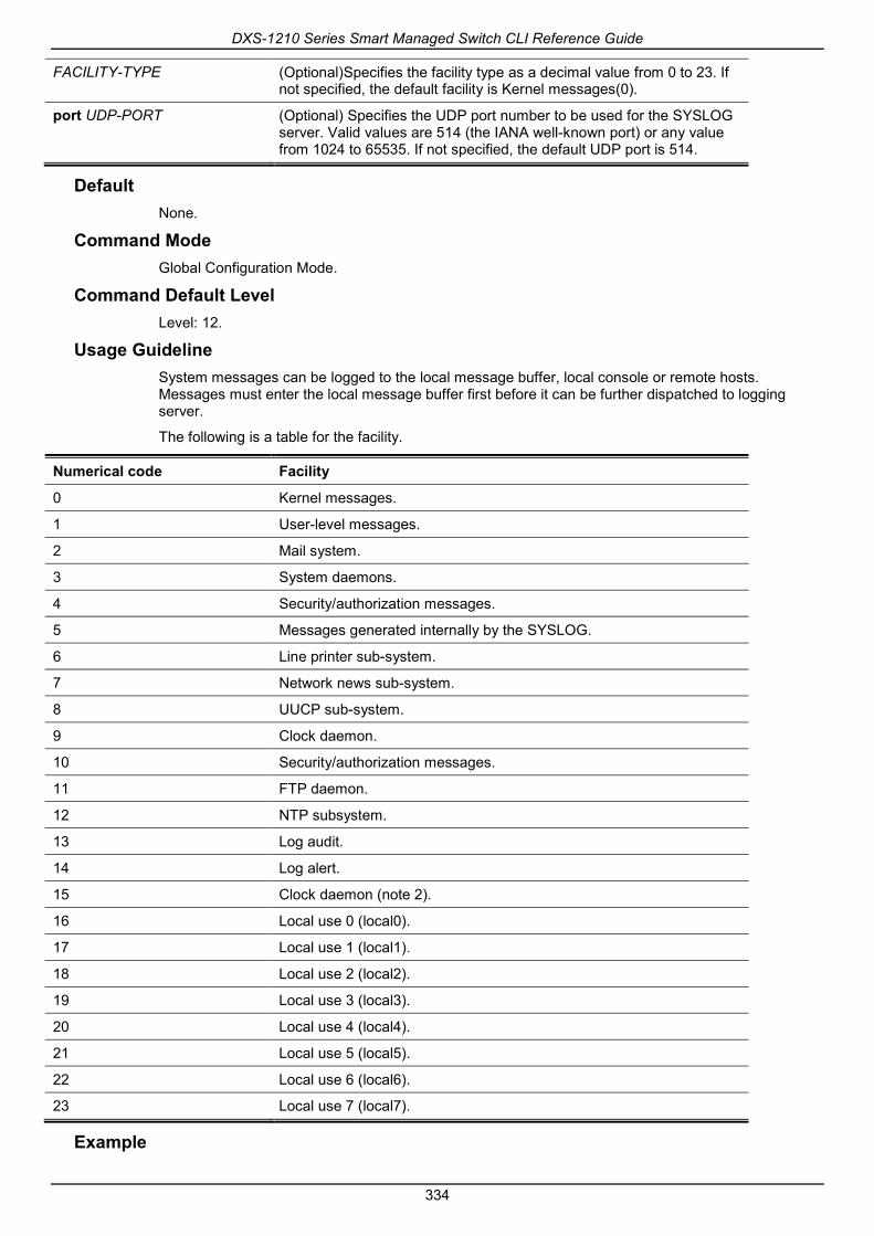
DXS-1210 Series Smart Managed Switch CLI Reference Guide
334
FACILITY-TYPE (Optional)Specifies the facility type as a decimal value from 0 to 23. If not specified, the default facility is Kernel messages(0).
port UDP-PORT (Optional) Specifies the UDP port number to be used for the SYSLOG server. Valid values are 514 (the IANA well-known port) or any value from 1024 to 65535. If not specified, the default UDP port is 514.
Default None.
Command Mode Global Configuration Mode.
Command Default Level Level: 12.
Usage Guideline System messages can be logged to the local message buffer, local console or remote hosts. Messages must enter the local message buffer first before it can be further dispatched to logging server.
The following is a table for the facility.
Numerical code Facility
0 Kernel messages.
1 User-level messages.
2 Mail system.
3 System daemons.
4 Security/authorization messages.
5 Messages generated internally by the SYSLOG.
6 Line printer sub-system.
7 Network news sub-system.
8 UUCP sub-system.
9 Clock daemon.
10 Security/authorization messages.
11 FTP daemon.
12 NTP subsystem.
13 Log audit.
14 Log alert.
15 Clock daemon (note 2).
16 Local use 0 (local0).
17 Local use 1 (local1).
18 Local use 2 (local2).
19 Local use 3 (local3).
20 Local use 4 (local4).
21 Local use 5 (local5).
22 Local use 6 (local6).
23 Local use 7 (local7).
Example

DXS-1210 Series Smart Managed Switch CLI Reference Guide
335
This example shows how to enable the logging of system messages with a severity higher than warnings to the remote host 20.3.3.3. Switch# configure terminal
Switch(config)#logging server 20.3.3.3 severity warnings
Switch(config)#
43-4 logging source-interface This command is used to specify the interface whose IP address will be used as the source address for sending the SYSLOG packet. Use the no form of this command to revert to the default setting.
logging source-interface INTERFACE-ID
no logging source-interface
Parameters
INTERFACE-ID Specifies the interface whose IP address will be used as the source address of the SYSLOG packet.
Default By default, the IP address of the closest interface will be used.
Command Mode Global Configuration Mode.
Command Default Level Level: 12.
Usage Guideline Use this command to specify the interface whose IP address will be used as the source address of the SYSLOG packet.
Example This example shows how to configure VLAN100 as the source interface for SYSLOG packets. Switch# configure terminal
Switch(config)#logging source-interface vlan 100
Switch(config)#
43-5 show logging This command is used to display the system messages logged in the local message buffer.
show logging [all | [REF-SEQ] [increase NN | decrease NN]]
show logging info
Parameters
all Specifies to display all log entries starting from the latest message..
REF-SEQ Specifies to start the display from the reference sequence number.
increase NN Specifies the number of messages that occurred after the specified reference sequence number. If the reference index is not specified, it

DXS-1210 Series Smart Managed Switch CLI Reference Guide
336
starts from the eldest message in the buffer.
decrease NN Specifies the number of messages that occurred prior to the specified reference sequence number. If the reference index is not specified, the message display starts from the last message written in the buffer.
info Specifies to display the system log global setting.
Default None.
Command Mode EXEC Mode or Any Configuration Mode.
Command Default Level Level: 1.
Usage Guideline Use this command to display the system messages logged in the local message buffer.
Each message logged in the message buffer is associated with a sequence number. As a message is logged, a sequence number starting from 1 is allocated. The sequence number will roll back to 1 when it reaches 100000.
When the user specifies to display a number of messages following the reference sequence number, the oldest messages are displayed prior to the newer messages. When the user specifies to display a number of messages prior to the reference sequence number, the newer messages are displayed prior to the later messages.
If the command is issued without options, the system will display up to 200 entries starting from the latest message.
Example This example shows how to display the messages in the local message buffer. switch# show logging
Total number of buffered messages: 2
#2 2013-08-02 16:37:36 INFO(6) Logout through Console (Username: Anonymous)
#1 2013-08-02 16:35:54 INFO(6) Port eth1/0/1 link up, 1000Mbps FULL duplex
switch#

DXS-1210 Series Smart Managed Switch CLI Reference Guide
337
44. Time and SNTP Commands 44-1 clock set
This command is used to manually set the system’s clock.
clock set HH:MM:SS DAY MONTH YEAR
Parameters
HH:MM:SS Specifies the current time in hours (24-hour format), minutes and seconds.
DAY Specifies the current day (by date) in the month.
MONTH Specifies the current month (by name, January, Jan, February, Feb, and so on).
YEAR Specifies the current year (no abbreviation).
Default None.
Command Mode Privilege EXEC Mode.
Command Default Level Level: 12.
Usage Guideline Generally, if the system is synchronized by a valid outside timing mechanism, such as SNTP, there is mp need to set the software clock. Use this command if no other time sources are available. The time specified in this command is assumed to be in the time zone specified by the configuration of the clock timezone command. The clock configured by this command will be applied to RTC if it is available. The configured clock will not be stored in the configuration file.
If the clock is manually set and the SNTP server is configured, the system will still try to sync the clock with the server. If the clock is manually set, but a new clock time is obtained by the SNTP server, the clock will be replaced by the new synced clock.
Example This example shows how to manually set the software clock to 6:00 p.m. on Jul4, 2014. Switch# clock set 18:00:00 4 Jul 2014
Switch#
44-2 clock summer-time This command is used to configure the system to automatically switch to summer time (daylight saving time). Use the no form of this command to configure the Switch to not automatically switch over to summer time.
clock summer-time recurring WEEK DAY MONTH HH:MM WEEK DAY MONTH HH:MM [OFFSET]
clock summer-time date DATE MONTH YEAR HH:MM DATE MONTH YEAR HH:MM [OFFSET]
no clock summer-time

DXS-1210 Series Smart Managed Switch CLI Reference Guide
338
Parameters
recurring Specifies that summer time should start and end on the specified week day of the specified month.
date Specifies that summer time should start and end on the specified date of the specified month.
WEEK Specifies the week of the month (1 to 4 or last).
DAY Specifies the day of the week (sun, mon, and so on).
DATE Specifies the date of the month (1 to 31).
MONTH Specifies the month (1 to 12).
YEAR Specifies the start and end years for the summer time data.
HH:MM Specifies the time (24 hours format ) in hours and minutes.
OFFSET (Optional) Specifies the number of minutes to add during summer time. The default value is 60. The range of this offset is 30, 60, 90 and 120.
Default By default, this option is disabled.
Command Mode Global Configuration Mode.
Command Default Level Level: 12.
Usage Guideline Use this command to automatically switch over to summer time. The command has two forms. One is the recurring form which is used to specify the time through the week and the day of the month. The other form is the date form which is used to specify the date of the month.
In both the date and recurring forms of the command, the first part of the command specifies when summer time begins, and the second part specifies when it ends.
Example This example shows how to specify that summer time starts on the first Sunday in June at 2 a.m. and ends on the last Sunday in October at 2 a.m. Switch# configure terminal
Switch(config)#clock summer-time recurring 1 sun jun 02:00 last sun oct 02:00
Switch(config)#
44-3 clock timezone This command is used to set the time zone for display purposes. Use the no form of this command to revert to the default setting.
clock timezone {+ | -} HOURS-OFFSET [MINUTES-OFFSET]
no clock timezone
Parameters
+ | - +: Specifies that time to be added to the UTC. -: Specifies that time to be subtracted from the UTC.
HOURS-OFFSET Specifies the hours difference from UTC.

DXS-1210 Series Smart Managed Switch CLI Reference Guide
339
MINUTES-OFFSET (Optional) Specifies the minutes difference from UTC.
Default By default, this option is set to UTC.
Command Mode Global Configuration Mode.
Command Default Level Level: 12.
Usage Guideline The time obtained by the SNTP server refers to the UTC time. The local time will be calculated based on UTC time, time zone, and the daylight saving configuration.
Example This example shows how to set the time zone to the Pacific Standard Time (PST), which is 8 hours ahead of UTC. Switch# configure terminal
Switch(config)# clock timezone - 8
Switch(config)#
44-4 show clock This command is used to display the time and date information.
show clock
Parameters None.
Default None.
Command Mode EXEC Mode or Any Configuration Mode.
Command Default Level Level: 1.
Usage Guideline This command also indicates the clock’s source. The clock source can be “No Time Source” or “SNTP”.
Example This example shows how to display the current time.

DXS-1210 Series Smart Managed Switch CLI Reference Guide
340
Switch# show clock
Current Time Source : SNTP
Current Time : 18:20:04, 2014-07-04
Time Zone : UTC +02:30
Daylight Saving Time : Recurring
Offset in Minutes : 30
Recurring From : Apr 2nd Tue 15:00
To : Oct 2nd Wed 15:30
Switch#
44-5 show sntp This command is used to display information about the SNTP server.
show sntp
Parameters None.
Default None.
Command Mode EXEC Mode or Any Configuration Mode.
Command Default Level Level: 1.
Usage Guideline This command is used to display information about the SNTP server.
Example This example shows how to display SNTP information. Switch# show sntp
SNTP Status :Enabled
SNTP Pool Interval : 720 seconds
SNTP Server Status:
SNTP Server Stratum Version Last Receive
---------------------------------------------- ------- ------- ---------------
10.0.0.11 8 4 00:02:02
10.0.0.12 7 4 00:01:02 Synced
10::2 ------- ------- ---------------
FE80::1111vlan1 ------- ------- ---------------
---------------------------------------------- ------- ------- ---------------
Total Entries:4
Switch#

DXS-1210 Series Smart Managed Switch CLI Reference Guide
341
44-6 sntp server This command is used to allow the system clock to be synchronized with an SNTP time server. Use the no form of this commandto remove a server from the list of SNTP servers.
sntp server {IP-ADDRESS | IPV6-ADDRESS}
no sntp server {IP-ADDRESS | IPV6-ADDRESS}
Parameters
IP-ADDRESS Specifies the IP address of the time server which provides the clock synchronization.
IPV6-ADDRESS Specifies the IPv6 address of the time server.
Default None.
Command Mode Global Configuration Mode.
Command Default Level Level: 12.
Usage Guideline SNTP is a compact, client-only version of the NTP. Unlike NTP, SNTP can only receive the time from NTP servers; it cannot be used to provide time services to other systems. SNTP typically provides time within 100 milliseconds of the accurate time, but it does not provide the complex filtering and statistical mechanisms of NTP. In addition, SNTP does not authenticate traffic, although you can configure extended access lists to provide some protection.
Create multiple SNTP servers by enter this command multiple times with different SNTP server IP addresses.
Use the no form of this command to delete the SNTP server entry. To delete an entry, specify the information exactly the same as the originally configured setting. The time obtained from the SNTP server refers to the UTC time.
Example This example shows how to configure a switch to allow its software clock to be synchronized with the clock by the SNTP server at IP address 192.168.22.44. Switch# configure terminal
Switch(config)# sntp server 192.168.22.44
Switch(config)#
44-7 sntp enable This command is used to enable the SNTP function. Use the no form of this command to disable the SNTP function.
sntp enable
no sntp enable
Parameters None.
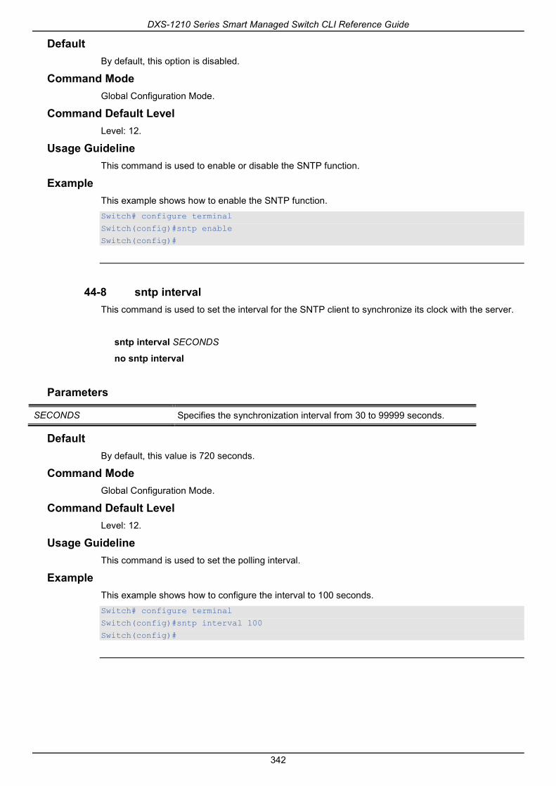
DXS-1210 Series Smart Managed Switch CLI Reference Guide
342
Default By default, this option is disabled.
Command Mode Global Configuration Mode.
Command Default Level Level: 12.
Usage Guideline This command is used to enable or disable the SNTP function.
Example This example shows how to enable the SNTP function. Switch# configure terminal
Switch(config)#sntp enable
Switch(config)#
44-8 sntp interval This command is used to set the interval for the SNTP client to synchronize its clock with the server.
sntp interval SECONDS
no sntp interval
Parameters
SECONDS Specifies the synchronization interval from 30 to 99999 seconds.
Default By default, this value is 720 seconds.
Command Mode Global Configuration Mode.
Command Default Level Level: 12.
Usage Guideline This command is used to set the polling interval.
Example This example shows how to configure the interval to 100 seconds. Switch# configure terminal
Switch(config)#sntp interval 100
Switch(config)#

DXS-1210 Series Smart Managed Switch CLI Reference Guide
343
45. Time Range Commands 45-1 periodic
This command is used to specify the period of time for a time range profile. This command is used in the time-range configuration mode.
periodic {daily HH:MM to HH:MM | weekly WEEKLY-DAY HH:MM to [WEEKLY-DAY] HH:MM}
no periodic {daily HH:MM to HH:MM | weekly WEEKLY-DAY HH:MM to [WEEKLY-DAY] HH:MM}
Parameters
daily HH:MM to HH:MM Specifies the time of the day, using the format HH:MM (for example, 18:30).
weekly WEEK-DAY HH:MM to [WEEK-DAY] HH:MM
Specifies the day of the week and the time of day in the format day HH:MM, where the day of the week is spelled out (monday, tuesday, wednesday, thursday, friday, saturday, and sunday). If the ending day of the week is the same as the starting day of the week, it can be omitted.
Default None.
Command Mode Time-range Configuration Mode.
Command Default Level Level: 12.
Usage Guideline A new period can be partially overlapped with an older one. If a new period’s starting and ending time is respectively the same as a previous period, an error message will be displayed and the new period will not be allowed. When specifying a period to remove, it must be the same period originally added and cannot be a partial range of a period or multiple periods configured. Otherwise, an error message will be displayed.
Example This example shows how to create a time-range that include daily 09:00 to 12:00, 00:00 Saturday to 00:00 Monday and delete the period for daily 09:00 to 12:00. Switch# configure terminal
Switch(config)#time-range rdtime
Switch(config-time-range)# periodic daily 9:00 to 12:00
Switch(config-time-range)# periodic weekly saturday 00:00 to monday 00:00
Switch(config-time-range)# no periodic daily 9:00 to 12:00
Switch(config-time-range)#
45-2 show time-range This command is used to display the time range profile configuration.
show time-range [NAME]

DXS-1210 Series Smart Managed Switch CLI Reference Guide
344
Parameters
NAME (Optional) Specifies the name of the time-range profile to be displayed.
Default None.
Command Mode EXEC Mode or Any Configuration Mode.
Command Default Level Level: 1.
Usage Guideline If the name is not specified, all configured time-range profiles will be displayed.
Example This example shows how to display all the configured time ranges. Switch#show time-range
Time Range Profile: rdtime
Daily 09:00 to 12:00
Weekly Saturday 00:00 to Monday 00:00
Time Range Profile: lunchtime
Daily 12:00 to 13:00
Total Entries: 2
Switch#
45-3 time-range This command is used to enter the time range configuration mode to define a time range. Use the no form of this command to delete a time range.
time-range NAME
no time-range NAME
Parameters
NAME Specifies the name of the time-range profile to be configured. The maximum length is 32 characters.
Default None.
Command Mode Global Configuration Mode.
Command Default Level Level: 12.
Usage Guideline

DXS-1210 Series Smart Managed Switch CLI Reference Guide
345
Use this command to enter the time range configuration mode before using the periodic command to specify a time period. When a time-range is created without any time interval (periodic) setting, it implies that there is not any active period for the time-range.
Example This example shows how to enter the time range configuration mode for the time-range profile, named “rdtime”. Switch# configure terminal
Switch(config)#time-range rdtime
Switch(config-time-range)#

DXS-1210 Series Smart Managed Switch CLI Reference Guide
346
46. Traffic Segmentation Commands 46-1 show traffic-segmentation forward
This command is used to display the traffic segmentation for some ports or all ports.
show traffic-segmentation forward [interface INTERFACE-ID [, | -]]
Parameters
interface INTERFACE-ID (Optional) Specifies ID of an interface. The acceptable interface will be physical port or port channel.
, (Optional) Specifies a series of interfaces, or separate a range of interfaces from a previous range. No space before and after the comma.
- (Optional) Specifies a range of interfaces. No space before and after the hyphen.
Default None.
Command Mode EXEC Mode or Any Configuration Mode.
Command Default Level Level: 1.
Usage Guideline While entering this command without any other keywords, the traffic segmentation configuration for all ports is displayed. Otherwise, only the specified interface’s traffic segmentation is displayed.
Example This example shows how to display the configuration of traffic segmentation for eth1/0/1. Switch# show traffic-segmentation forward interface eth 1/0/1
Interface Forwarding Domain
------------ -------------------------------------------
eth1/0/1 eth1/0/1, eth1/0/4-6
Total Entries: 1
Switch#
46-2 traffic-segmentation forward This command is used to restrict the Layer 2 packet forwarding domain of packets received by the configured port. Use the no form of this command to remove the specification of forwarding domain.
traffic-segmentation forward interface INTERFACE-ID [, | -]
no traffic-segmentation forward interface INTERFACE-ID [, | -]
Parameters

DXS-1210 Series Smart Managed Switch CLI Reference Guide
347
INTERFACE-ID Specifies the ID of an interface allowed. The allowed interfaces include physical port.
, (Optional) Specifies a series of interfaces, or separate a range of interfaces from a previous range. No space before and after the comma.
- (Optional) Specifies a range of interfaces. No space before and after the hyphen.
Default None.
Command Mode Interface Configuration Mode.
Command Default Level Level: 12.
Usage Guideline When traffic segmentation forwarding domain is specified, packets received by the port will be restricted in Layer 2 packet forwarding to interfaces within the domain. When the forwarding domain of a port is empty, Layer 2 forwarding for packets received by the port is not restricted.
The traffic-segmentation forward command can be entered multiple times. The following interfaces will be appended into the forwarding domain. Use the no form command will remove the specified interface from the traffic segmentation forward member list.
The traffic segmentation member list can be comprised of different interface types, for example port and port-channel in the same forwarding domain. If the interfaces specified by the command include a port-channel, all the member ports of this port-channel will be included in the forwarding domain.
If the forwarding domain of an interface is empty, then there is no restriction on Layer 2 forwarding of packets received by the port.
Example This example shows how to configure traffic segmentation. It restricts the flooding domain of eth1/0/1 to a set of ports, which are eth1/0/1 – eth1/0/6. Switch# configure terminal
Switch(config)#interface eth1/0/1
Switch(config-if)# traffic-segmentation forward interface range eth1/0/1-6
Switch(config-if)#

DXS-1210 Series Smart Managed Switch CLI Reference Guide
348
47. Virtual LAN (VLAN) Commands 47-1 acceptable-frame
This command is used to set the acceptable types of frames by a port. Use the no form of this command to revert to the default settings.
acceptable-frame {tagged-only | untagged-only | admit-all}
no acceptable-frame
Parameters
tagged-only Specifies that only tagged frames are admitted.
untagged-only Specifies that only untagged frames are admitted.
admit-all Specifies that all frames are admitted.
Default For the access VLAN mode, the default option is untagged-only.
For the other VLAN mode, the default option is admit-all.
Command Mode Interface Configuration Mode.
Command Default Level Level: 12.
Usage Guideline This command is used to set the acceptable types of frames by a port.
Example This example shows how to set the acceptable frame type to tagged-only for port eth1/0/1. Switch# configure terminal
Switch(config)#interface eth 1/0/1
Switch(config-if)# acceptable-frame tagged-only
Switch(config-if)#
47-2 ingress-checking This command is used to enable ingress checking for frames received by a port. Use the no form of this command to disable the ingress check.
ingress-checking
no ingress-checking
Parameters None.
Default By default, this option is enabled.
Command Mode

DXS-1210 Series Smart Managed Switch CLI Reference Guide
349
Interface Configuration Mode.
Command Default Level Level: 12.
Usage Guideline Use this command to enable ingress checking for packets received by the interface. If ingress checking is enabled, the packet will be dropped if the received port is not a member port of the VLAN classified for the received packet.
Example This example shows how to set ingress checking to enabled port eth1/0/1. Switch# configure terminal
Switch(config)#interface eth 1/0/1
Switch(config-if)# ingress-checking
Switch(config-if)#
47-3 show vlan This command is used to display the parameters for all configured VLANs or one VLAN on the Switch.
show vlan [VLAN-ID [, | -] | interface [INTERFACE-ID [, | -]]]
Parameters
VLAN-ID (Optional) Specifies a list of VLANs to display the member port information. If the VLAN is not specified, all VLANs are displayed. The valid range is from 1 to 4094.
interface INTERFACE-ID (Optional) Specifies the port to display the VLAN related setting.
, (Optional) Specifies a series of interfaces, or separate a range of interfaces from a previous range. No space before and after the comma.
- (Optional) Specifies a range of interfaces. No space before and after the hyphen.
Default None.
Command Mode EXEC Mode or Any Configuration Mode.
Command Default Level Level: 1.
Usage Guideline This command is used to display the parameters for all configured VLANs or one VLAN on the Switch.
Example This example shows how to display all the current VLAN entries.

DXS-1210 Series Smart Managed Switch CLI Reference Guide
350
Switch#show vlan
VLAN 1
Name : default
Tagged Member Ports :
Untagged Member Ports : 1/0/1-1/0/28
Total Entries : 1
Switch#
This example shows how to display the PVID, ingress checking, and acceptable frame type information for ports eth1/0/1-1/0/4. Switch#show vlan interface eth 1/0/1-1/0/4
eth1/0/1
VLAN mode : Hybrid
Native VLAN : 1
Hybrid untagged VLAN : 1
Hybrid tagged VLAN :
Ingress checking : Enabled
Acceptable frame type : Admit-All
Dynamic tagged VLAN :
eth1/0/2
VLAN mode : Hybrid
Native VLAN : 1
Hybrid untagged VLAN : 1
Hybrid tagged VLAN :
Ingress checking : Enabled
Acceptable frame type : Admit-All
Dynamic tagged VLAN :
eth1/0/3
VLAN mode : Hybrid
Native VLAN : 1
Hybrid untagged VLAN : 1
Hybrid tagged VLAN :
Ingress checking : Enabled
Acceptable frame type : Admit-All
Dynamic tagged VLAN :
eth1/0/4
VLAN mode : Hybrid
Native VLAN : 1
Hybrid untagged VLAN : 1
Hybrid tagged VLAN :
Ingress checking : Enabled
Acceptable frame type : Admit-All
Dynamic tagged VLAN :
Switch#

DXS-1210 Series Smart Managed Switch CLI Reference Guide
351
47-4 switchport access vlan This command is used to specify the access VLAN for an interface. Use the no form of this command to revert to the default setting.
switchport access vlan VLAN-ID
no switchport access vlan
Parameters
access vlan VLAN-ID Specifies the access VLAN of the interface.
Default By default, this access VLAN is VLAN 1.
Command Mode Interface Configuration Mode.
Command Default Level Level: 12.
Usage Guideline The command takes effect when the interface is set to access mode. The VLAN specified as the access VLAN does not need to exist to configure the command.
Only one access VLAN can be specified. The succeeding command overwrites the previous command.
Example This example shows how to configurethe interface 1/0/1 to access mode with access VLAN 1000. Switch# configure terminal
Switch(config)#interface eth 1/0/1
Switch(config-if)# switchport mode access
Switch(config-if)# switchport access vlan 1000
Switch(config-if)#
47-5 switchport hybrid allowed vlan This command is used to specify the tagged or untagged VLANs for a hybrid port. Use the no form of this command to revert to the default setting.
switchport hybrid allowed vlan {[add] {tagged | untagged} | remove} VLAN-ID [, | -]
no switchport hybrid allowed vlan
Parameters
add Specifies the port will be added into the specified VLAN(s).
remove Specifies the port will be removed from the specified VLAN(s).
tagged Specifies the port as a tagged member of the specified VLAN(s).
untagged Specifies the port as an untagged member of the specified VLAN(s).
VLAN-ID Specified the allowed VLAN list or the VLAN list to be added to or removed from the allow VLAN list. If nooption is specified, the specified VLAN list will overwrite the allowed VLAN list.

DXS-1210 Series Smart Managed Switch CLI Reference Guide
352
, (Optional) Specifies a series of VLANs, or separate a range of VLANs from a previous range. No space is required before and after the comma.
- (Optional) Specifies a range of VLANs. No space is required before and after the hyphen.
Default By default, a hybrid port is an untagged member port of VLAN 1.
Command Mode Interface Configuration Mode.
Command Default Level Level: 12.
Usage Guideline By setting the hybrid VLAN command multiple times with different VLAN IDs, a port can be a tagged member port or an untagged member port of multiple VLANs.
When the allowed VLAN is only specified as the VLAN ID, the succeeding command will overwrites the previous command. If the new untagged allowed VLAN list is overlap with the current tagged allowed VLAN list, the overlap part will change to the untagged allowed VLAN. On the other hand, if the new tagged allowed VLAN list is overlap with current untagged allowed VLAN list, the overlap part will change to the tagged allowed VLAN. The last command will take effect. The VLAN does not need to exist to configure the command.
Example This example shows how to configure interface eth1/0/1 to be a tagged member of VLAN 1000 and an untagged member of VLAN 2000 and 3000. Switch# configure terminal
Switch(config)#interface eth 1/0/1
Switch(config-if)# switchport mode hybrid
Switch(config-if)# switchport hybrid allowed vlan add tagged 1000
Switch(config-if)# switchport hybrid allowed vlan add untagged 2000,3000
Switch(config-if)#
47-6 switchport hybrid native vlan This command is used to specify the native VLAN ID of a hybrid port. Use the no form of this command to reset the native VLAN to the default setting.
switchport hybrid native vlan VLAN-ID
no switchport hybrid native vlan
Parameters
vlan VLAN-ID Specifies the native VLAN of a hybrid port.
Default By default, the native VLAN of a hybrid port is VLAN 1.
Command Mode Interface Configuration Mode.
Command Default Level Level: 12.

DXS-1210 Series Smart Managed Switch CLI Reference Guide
353
Usage Guideline When configuring the hybrid port join to its native VLAN, use the switchport hybrid allowed vlan command to add the native VLAN into its allowed VLAN. The specified VLAN does not need to exist to apply the command. The command takes effect when the interface is set to hybrid mode.
Example This example shows how to configure interface eth1/0/1 to become a hybrid interface and configure the PVID to 20. Switch# configure terminal
Switch(config)#interface eth 1/0/1
Switch(config-if)# switchport mode hybrid
Switch(config-if)# switchport hybrid allowed vlan add untagged 1000,20
Switch(config-if)# switchport hybrid native vlan 20
Switch(config-if)#
47-7 switchport mode This command is used to specify the VLAN mode for the port. Use the no form of this command to revert to the default setting.
switchport mode {access | hybrid | trunk}
no switchport mode
Parameters
access Specifies the port as an access port.
hybrid Specifies the port as a hybrid port.
trunk Specifies the port as a trunk port.
Default By default, this option is hybrid.
Command Mode Interface Configuration Mode.
Command Default Level Level: 12.
Usage Guideline When a port is set to access mode, this port will be an untagged member of the access VLAN configured for the port. When a port is set to hybrid mode, the port can be an untagged or tagged member of any VLAN configured.
When a port is set to trunk mode, this port is either a tagged or untagged member port of its native VLAN and can be a tagged member of other VLANs configured. The purpose of a trunk port is to support the switch-to-switch connection.
When the switch-port mode is changed, the VLAN related setting associated with previous mode will be lost.
Example This example shows how to set the interface eth1/0/1 as a trunk port.

DXS-1210 Series Smart Managed Switch CLI Reference Guide
354
Switch# configure terminal
Switch(config)#interface eth 1/0/1
Switch(config-if)# switchport mode trunk
Switch(config-if)#
47-8 switchport trunk allowed vlan This command is used to configure the VLANs that are allowed to receive and send traffic on the specified interface in a tagged format. Use the no form of this command to revert to the default setting.
switchport trunk allowed vlan {all | [add | remove | except] VLAN-ID [, | -]}
no switchport trunk allowed vlan
Parameters
all Specifies that all VLANs are allowed on the interface.
add Specifies to add the specified VLAN list to the allowed VLAN list.
remove Specifies to remove the specified VLAN list from the allowed VLAN list.
except Specifies that all VLANs except the VLANs in the exception list are allowed.
VLAN-ID Specifies the allow VLAN list or the VLAN list to be added to or removed from the allow VLAN list.
, (Optional) Specifies a series of VLANs, or separate a range of VLANs from a previous range. No space is required before and after the comma.
- (Optional) Specifies a range of VLANs. No space is required before and after the hyphen.
Default By default, all VLANs are allowed.
Command Mode Interface Configuration Mode.
Command Default Level Level: 12.
Usage Guideline This command only takes effect when the interface is set to trunk mode. If a VLAN is allowed on a trunk port, the port will become the tagged member of the VLAN. When the allowed VLAN option is set to all, the port will be automatically added to all the VLAN created by the system.
Example This example shows how to configure interface eth1/0/1 as a tagged member of VLAN 1000. Switch# configure terminal
Switch(config)#interface eth 1/0/1
Switch(config-if)# switchport mode trunk
Switch(config-if)# switchport trunk allowed vlan add 1000
Switch(config-if)#

DXS-1210 Series Smart Managed Switch CLI Reference Guide
355
47-9 switchport trunk native vlan This command is used to specify the native VLAN ID of a trunk mode interface. Use the no interface command to reset to the native VLAN ID to the default setting.
switchport trunk native vlan {VLAN-ID | tag}
no switchport trunk native vlan [tag]
Parameters
VLAN-ID Specifies the native VLAN for a trunk port.
tag Specifies to enable the tagging mode of the native VLAN.
Default By default, the native VLAN is 1, untagged mode.
Command Mode Interface Configuration Mode.
Command Default Level Level: 12.
Usage Guideline The command only takes effect when the interface is set to trunk mode. When a trunk port native VLAN is set to tagged mode, normally the acceptable frame type of the port should be set to “tagged-only” to only accept tagged frames. When a trunk port works in the untagged mode for a native VLAN, transmitting untagged packet for a native VLAN and tagged packets for all other VLANs and the acceptable frame types of the port has to be set to “admit-all” in order to function correctly.
The specified VLAN does not need to exist to apply the command.
Example This example shows how to configure interface eth1/0/1 as a trunk interface and configures the native VLAN to 20. Switch# configure terminal
Switch(config)#interface eth 1/0/1
Switch(config-if)# switchport mode trunk
Switch(config-if)# switchport trunk native vlan 20
Switch(config-if)#
47-10 vlan This command is used to add VLANs and enter the VLAN configuration mode. Use the no form of this command to remove VLANs.
vlan VLAN-ID [, | -]
no vlan VLAN-ID [, | -]
Parameters
VLAN-ID Specifies the ID of the VLAN to be added, removed or configured. The valid VLAN ID range is from 1 to 4094. VLAN ID 1 cannot be removed.
, Specifies a series of VLANs, or separate a range of VLANs from a previous range. No space is required before and after the comma.

DXS-1210 Series Smart Managed Switch CLI Reference Guide
356
- (Optional) Specifies a range of VLANs. No space is required before and after the hyphen.
Default The VLAN ID 1 exists in the system as the default VLAN.
Command Mode Global Configuration Mode.
Command Default Level Level: 12.
Usage Guideline Use the vlan global configuration command to create VLANs. Entering the vlan command with a VLAN ID enters the VLAN configuration mode. Entering the VLAN ID of an existing VLAN does not create a new VLAN, but allows the user to modify the VLAN parameters for the specified VLAN. When the user enters the VLAN ID of a new VLAN, the VLAN will be automatically created.
Use the no vlan command to remove a VLAN. The default VLAN cannot be removed. If the removed VLAN is a port’s access VLAN, the port’s access VLAN will be reset to VLAN 1.
Example This example shows how to add new VLANs, assigning the new VLANs with the VLAN IDs 1000 to 1005. Switch# configure terminal
Switch(config)#vlan 1000-1005
Switch(config-vlan)#
47-11 name This command is used to specify the name of a VLAN. Use the no form of this command to reset the VLAN name to the default VLAN name.
name VLAN-NAME
no name
Parameters
VLAN-NAME Specifies the VLAN name, with a maximum of 32 characters. The VLAN name must be unique within the administrative domain.
Default The default VLAN name is VLANx, where x represents four numeric digits (including the leading zeros) that are equal to the VLAN ID.
Command Mode VLAN Configuration Mode.
Command Default Level Level: 12.
Usage Guideline Use this command to specify the name of a VLAN. The VLAN name must be unique within the administrative domain.
Example

DXS-1210 Series Smart Managed Switch CLI Reference Guide
357
This example shows how to configure the VLAN name of VLAN 1000 to be “admin-vlan”. Switch# configure terminal
Switch(config)#vlan 1000
Switch(config-vlan)# name admin-vlan
Switch(config-vlan)#
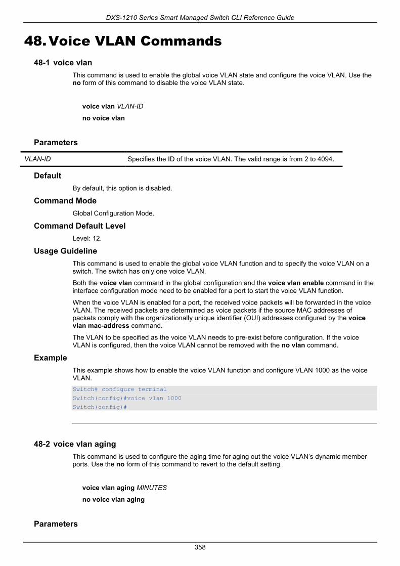
DXS-1210 Series Smart Managed Switch CLI Reference Guide
358
48. Voice VLAN Commands 48-1 voice vlan
This command is used to enable the global voice VLAN state and configure the voice VLAN. Use the no form of this command to disable the voice VLAN state.
voice vlan VLAN-ID
no voice vlan
Parameters
VLAN-ID Specifies the ID of the voice VLAN. The valid range is from 2 to 4094.
Default By default, this option is disabled.
Command Mode Global Configuration Mode.
Command Default Level Level: 12.
Usage Guideline This command is used to enable the global voice VLAN function and to specify the voice VLAN on a switch. The switch has only one voice VLAN.
Both the voice vlan command in the global configuration and the voice vlan enable command in the interface configuration mode need to be enabled for a port to start the voice VLAN function.
When the voice VLAN is enabled for a port, the received voice packets will be forwarded in the voice VLAN. The received packets are determined as voice packets if the source MAC addresses of packets comply with the organizationally unique identifier (OUI) addresses configured by the voice vlan mac-address command.
The VLAN to be specified as the voice VLAN needs to pre-exist before configuration. If the voice VLAN is configured, then the voice VLAN cannot be removed with the no vlan command.
Example This example shows how to enable the voice VLAN function and configure VLAN 1000 as the voice VLAN. Switch# configure terminal
Switch(config)#voice vlan 1000
Switch(config)#
48-2 voice vlan aging This command is used to configure the aging time for aging out the voice VLAN’s dynamic member ports. Use the no form of this command to revert to the default setting.
voice vlan aging MINUTES
no voice vlan aging
Parameters

DXS-1210 Series Smart Managed Switch CLI Reference Guide
359
MINUTES Specifies the aging time of the voice VLAN. The valid range is from 1 to 65535 minutes.
Default By default, this value is 720 minutes.
Command Mode Global Configuration Mode.
Command Default Level Level: 12.
Usage Guideline Use this command to configure the aging time for aging out the voice device and the voice VLAN automatically learned member ports. When the last voice device connected to the port stops sending traffic and the MAC address of this voice device is aged out from FDB, the voice VLAN aging timer will be started. The port will be removed from the voice VLAN after the expiration of the voice VLAN aging timer. If voice traffic resumes during the aging time, the aging timer will be cancelled.
Example This example shows how to configure the aging time of the voice VLAN to 30 minutes. Switch# configure terminal
Switch(config)#voice vlan aging 30
Switch(config)#
48-3 voice vlan enable This command is used to enable the voice VLAN state of ports. Use the no form of this command to disable the voice VLAN’sport state.
voice vlan enable
no voice vlan enable
Parameters None.
Default By default, this option is disabled.
Command Mode Interface Configuration Mode.
Command Default Level Level: 12.
Usage Guideline The command takes effect for access ports or hybrid ports. Use the voice vlan enable command to enable the voice VLAN function for ports. Both the voice vlan command in the global configuration and the voice vlan enable command in the interface configuration mode need to be enabled for a port to start the voice VLAN function.
Example This example shows how to enable the voice VLAN function on the physical port eth1/0/1.

DXS-1210 Series Smart Managed Switch CLI Reference Guide
360
Switch# configure terminal
Switch(config)#interface eth 1/0/1
Switch(config-if)# voice vlan enable
Switch(config-if)#
48-4 voice vlan mac-address This command is used to add the user-defined voice device OUI. Use the no form of this command to delete the user-defined voice device OUI.
voice vlan mac-address MAC-ADDRESS MASK [description TEXT]
no voice vlan mac-address MAC-ADDRESS MASK
Parameters
MAC-ADDRES Specifies the OUI MAC address.
MASK Specifies the OUI MAC address matching bitmask.
description TEXT (Optional) Specifies the description for the user defined OUI with a maximum of 32 characters.
Default The default OUI is listed in the following table:
OUI Vendor
00:E0:BB 3COM
00:03:6B Cisco
00:E0:75 Veritel
00:D0:1E Pingtel
00:01:E3 Siemens
00:60:B9 NEC/Philips
00:0F:E2 Huawei-3COM
00:09:6E Avaya
Command Mode Global Configuration Mode.
Command Default Level Level: 12.
Usage Guideline Use this command to add a user-defined OUI for the voice VLAN. The OUI for the voice VLAN is used to identify the voice traffic by using the voice VLAN function. If the source MAC addresses of the received packet matches any of the OUI patterns, the received packet is determined as a voice packet.
The user-defined OUI cannot be the same as the default OUI. The default OUI cannot be deleted.
Example This example shows how to add a user-defined OUI for voice devices.

DXS-1210 Series Smart Managed Switch CLI Reference Guide
361
Switch# configure terminal
Switch(config)#voice vlan mac-address 00-02-03-00-00-00 FF-FF-FF-00-00-00 description User1
Switch(config)#
48-5 voice vlan mode This command is used to enable the automatic learning of the port as voice VLAN member ports. Use the no form of this command to disable the automatic learning.
voice vlan mode {manual | auto {tag | untag}}
no voice vlan mode
Parameters
manual Specifies that voice VLAN membership will be manually configured.
auto Specifies that voice VLAN membership will be automatically learned.
tag Specifies to learn voice VLAN tagged members.
untag Specifies to learn voice VLAN untagged members.
Default By default, this option is set to untag and auto.
Command Mode Interface Configuration Mode.
Command Default Level Level: 12.
Usage Guideline Use this command to configure automatic learning or manual configuration of voice VLAN member ports.
If auto-learning is enabled, the port will automatically be learned as a voice VLAN member. This membership will be automatically be aged out. When the port is working in the auto tagged mode and the port captures a voice device through the device's OUI, it will join the voice VLAN as a tagged member automatically. When the voice device sends tagged packets, the switch will change its priority. When the voice device sends untagged packets, it will forward them in port's PVID VLAN.
When the port is working in auto untagged mode, and the port captures a voice device through the device's OUI, it will join the voice VLAN as an untagged member automatically. When the voice device sends tagged packets, the switch will change its priority. When the voice device sends untagged packets, it will forward them in voice VLAN.
When the switch receives LLDP-MED packets, it checks the VLAN ID, tagged flag, and priority flag. The switch should follow the tagged flag and priority setting.
If auto learning is disabled, the user should use the switchport hybrid vlan command to configure the port as a voice VLAN tagged or untagged member port.
Example This example shows how to configure physical port eth1/0/1 to be in the auto tag mode. Switch# configure terminal
Switch(config)#interface eth 1/0/1
Switch(config-if)# voice vlan mode auto tag
Switch(config-if)#

DXS-1210 Series Smart Managed Switch CLI Reference Guide
362
48-6 voice vlan qos This command is used to configure the CoS priority for the incoming voice VLAN traffic. Use the no form of this command to revert to the default setting.
voice vlan qos COS-VALUE
no voice vlan qos
Parameters
COS-VALUE Specifies the priority of the voice VLAN. This value must be between 0 and 7.
Default By default, this value is 5.
Command Mode Global Configuration Mode.
Command Default Level Level: 12.
Usage Guideline The voice packets arriving at the voice VLAN enabled port are marked to the CoS specified by the command. The remarking of CoS allows the voice VLAN traffic to be distinguished from data traffic in quality of service.
Example This example shows how to configure the priority of the voice VLAN to be 7. Switch# configure terminal
Switch(config)#voice vlan qos 7
Switch(config)#
48-7 show voice vlan This command is used to display the voice VLAN configurations.
show voice vlan [interface [INTERFACE-ID [, | -]]]
show voice vlan {device | lldpmed device} [interface INTERFACE-ID [, | -]]
Parameters
interface (Optional) Specifies to display voice VLAN information of ports.
INTERFACE-ID (Optional) Specifies the interface to display.
, (Optional)Specifies a series of interfaces, or separate a range of interfaces from a previous range. No space is allowed before and after the comma.
- (Optional)Specifies a range of interfaces. No space is allowed before and after the hyphen.
device (Optional) Specifies to display the voice devices learned by OUI.

DXS-1210 Series Smart Managed Switch CLI Reference Guide
363
lldp-med device (Optional) Specifies to display the voice devices learned by LLDP-MED.
Default None.
Command Mode EXEC Mode or Any Configuration Mode.
Command Default Level Level: 1.
Usage Guideline This command is used to display the voice VLAN configurations.
Example This example shows how to display the voice VLAN global settings. Switch# show voice vlan
Voice VLAN ID : 1000
Voice VLAN CoS : 7
Aging Time : 30 minutes
Member Ports : eth1/0/1-1/0/5
Dynamic Member Ports : eth1/0/1-1/0/3
Voice VLAN OUI:
OUI Address Mask Description
---------------- ----------------- -------------
00-01-E3-00-00-00 FF-FF-FF-00-00-00 Siemens
00-03-6B-00-00-00 FF-FF-FF-00-00-00 Cisco
00-09-6E-00-00-00 FF-FF-FF-00-00-00 Avaya
00-0F-E2-00-00-00 FF-FF-FF-00-00-00 Huawei&3COM
00-60-B9-00-00-00 FF-FF-FF-00-00-00 NEC&Philips
00-D0-1E-00-00-00 FF-FF-FF-00-00-00 Pingtel
00-E0-75-00-00-00 FF-FF-FF-00-00-00 Veritel
00-E0-BB-00-00-00 FF-FF-FF-00-00-00 3COM
00-02-03-00-00-00 FF-FF-FF-00-00-00 User1
Total OUI: 9
Switch#
This example shows how to display the voice VLAN information of ports. Switch# show voice vlan interface eth 1/0/1-5
Interface State Mode
------------ ---------- ------------
eth1/0/1 Enabled Auto/Tag
eth1/0/2 Enabled Manual
eth1/0/3 Enabled Manual
eth1/0/4 Enabled Auto/Untag
eth1/0/5 Disabled Manual
Switch#
This example shows how to display the learned voice devices on ports eth1/0/1-1/0/2.

DXS-1210 Series Smart Managed Switch CLI Reference Guide
364
Switch# show voice vlan device interface eth 1/0/1-2
Interface Device Address Start Time Status
--------- ------------------ ----------------- -------
eth1/0/1 00-03-6B-00-00-01 2012-03-19 09:00 Active
eth1/0/1 00-03-6B-00-00-02 2012-03-20 10:09 Aging
eth1/0/1 00-03-6B-00-00-05 2012-03-20 12:04 Active
eth1/0/2 00-03-6B-00-00-0a 2012-03-19 08:11 Aging
eth1/0/2 33-00-61-10-00-11 2012-03-20 06:45 Aging
Total Entries: 5
Switch#
This example shows how to display the learned LLDP-MED voice devices on ports eth1/0/1-1/0/2. Switch# show voice vlan lldpmed device interface eth 1/0/1-2
Index : 1
Interface : eth1/0/1
Chassis ID Subtype : MAC Address
Chassis ID : 00-E0-BB-00-00-11
Port ID Subtype : Network Address
Port ID : 172.18.1.1
Create Time : 2012-03-19 10:00
Remain Time : 108 Seconds
Index : 2
Interface : eth1/0/2
Chassis ID Subtype : MAC Address
Chassis ID : 00-E0-BB-00-00-12
Port ID Subtype : Network Address
Port ID : 172.18.1.2
Create Time : 2012-03-20 11:00
Remain Time : 105 Seconds
Total Entries: 2
Switch#

DXS-1210 Series Smart Managed Switch CLI Reference Guide
365
Appendix A - System Log Entries The following table lists all possible entries and their corresponding meanings that will appear in the System Log of this switch.
802.1X
Log Description Severity
Event description: 802.1X Authentication failure. Log Message: 802.1X authentication fails from (Username: <username>, Port: <interface-id>, MAC: <mac-address>) Parameters description:
username: The user that is being authenticated.. interface-id: The switch interface number. mac-address: The MAC address of the authenticated device.
Warning
Event description: 802.1X Authentication successful. Log Message: 802.1X authentication succeeds from (Username: <username>, Port: <interface-id>, MAC: <mac-address>) Parameters description:
username: The user that is being authenticated. interface-id: The interface name. mac-address: The MAC address of the authenticated device.
Informational
AAA
Log Description Severity
Event description: This log will be generated when RADIUS assigned a invalid VLAN ID attributes. Log Message: Invalid vlan assignment by radius with vlan <vid>, port <interface-id> Parameters description:
vid: The invalid assign VLAN ID that authorized by from RADIUS server. interface–id: It indicates the port number of the client authenticated.
Warning
Event description: This log will be generated when RADIUS assigned a invalid priority attributes. Log Message: Invalid port default 802.1p assignment by radius with 802.1p: <priority>, port < interface -id> Parameters description:
priority: The invalid assign priority that authorized by from RADIUS server. interface–id: It indicates the port number of the client authenticated.
Warning
Event description: This log will be generated when RADIUS assigned a invalid bandwidth attributes. Log Message: Invalid bandwidth assignment by radius with type <direction> rate <threshold>, port <interface -id> Parameters description:
direction: It indicates the direction for bandwidth control, e.g.: TX or RX. threshold: The invalid assign threshold of bandwidth that authorized by
Warning

DXS-1210 Series Smart Managed Switch CLI Reference Guide
366
from RADIUS server. interface–id: It indicates the port number of the client authenticated.
Event description: This log will be generated when request RADIUS assignment for a 802.1X mac based(Host Mode is Multi Auth) port. Log Message: The port <interface -id> is set to 802.1X mac based, it does not support radius assignment. Parameters description:
interface–id: It indicates the port number of the Host Mode is Multi Auth port.
Warning
Event description: This log will be generated when request RADIUS assignment for a igmp snooping router port. Log Message: The port eth <interface -id> is set to a router port of igmp snooping, it does not support radius assignment. Parameters description:
interface–id: It indicates the port number of igmp snooping router port.
Warning
Configuration/Firmware/Log
Log Description Severity
Event description: Firmware upgraded successfully.
Log Message:
Firmware upgraded successfully via <session>!
Parameters description:
session: The user’s session.
Informational
Event description: Firmware upgraded failure.
Log Message:
Firmware upgraded failure via <session>!
Parameters description:
session: The user’s session.
Warning
Event description: Firmware backup successfully.
Log Message:
Firmware backup successful via <session>
Parameters description:
session: The user’s session.
Informational
Event description: Firmware backup failure.
Log Message: Log Message:[Unit <unitID>, ]Firmware uploaded by <session> unsuccessfully (Username: <username>[, IP: <ipaddr>, MAC: <macaddr>], Server IP: <serverIP>, File Name: <pathFile>)
Firmware backup failure via <session>!
Parameters description:
session: The user’s session.
Warning
Event description: Configuration restore successfully.
Log Message:
Configuration restore successful via <session>
Parameters description:
Informational

DXS-1210 Series Smart Managed Switch CLI Reference Guide
367
session: The user’s session.
Event description: Configuration restore failure.
Log Message:
Configuration restore failure via <session>!
Parameters description:
session: The user’s session.
Warning
Event description: Configuration backup successfully.
Log Message:
Configuration backup successfull via <session>.
Parameters description:
session: The user’s session.
Informational
Event description: Configuration backup failure.
Log Message:
Configuration backup failure via <session>!
Parameters description:
session: The user’s session.
Warning
Event description: Configuration save successfully.
Log Message: Configuration save successful. Informational
Event description: Configuration save failure.
Log Message: Configuration save failure. Warning
Event description: System log backup successfully.
Log Message: System log backup successful via <session>.
Parameters description:
session: The user’s session.
Informational
Event description: System log backup failure.
Log Message: System log backup failure via <session>!
Parameters description:
session: The user’s session.
Warning
Interface
Log Description Severity
Event description:When port is down Log Message: Port <port-type>< interface-id> link down Parameters description:
port-type: port type interface-id: Interface name
Informational
Event description:When port is up Log Message: Port <port-type>< interface-id> link up, <link-speed> Parameters description:
port-type: port type interface-id: Interface name
Informational

DXS-1210 Series Smart Managed Switch CLI Reference Guide
368
link-speed: port link speed.
LACP
Log Description Severity
Event description: Link Aggregation Group link up. Log Message:Trunk group< group_id > link up. Parameters description:
group_id: The group id of the link up aggregation group.
Informational
Event description: Link Aggregation Group link down. Log Message: Trunk group< group_id > link down. Parameters description:
group_id: The group id of the link down aggregation group.
Informational
Event description: Member port attach to Link Aggregation Group. Log Message:Port <port_id> attach to Trunk group<group_id >. Parameters description:
port_id: The port id attached to aggregation group. group_id: The group id of the aggregation group that port attach to.
Informational
Event description: Member port detach from Link Aggregation Group. Log Message: Port <port_id> detach from Trunk group< group_id >. Parameters description:
port_id: The port id detached from aggregation group. group_id: The group id of the aggregation group that port detach from.
Informational
LBD
Log Description Severity
Event description: Record the event when an interface detect loop. Log Message:Port <interface-id> LBD loop occurred. Port blocked. Parameters description:
interface-id:Interface on which loop is detected.
Critical
Event description: Record the event when an interface detect loop. Log Message: Port <interface-id> LBD loop occurred. Port blocked at VID <vlan-id>. Parameters description:
interface-id:Interface on which loop is detected. vlan-id: VLAN on which loop is detected.
Critical
Event description: Record the event when an interface loop recovered Log Message: Port <interface-id> LBD loop recovered. Loop detection restarted. Parameters description:
interface-id:Interface on which loop is detected.
Informational
Event description: Record the event when an interface loop recovered. Log Message: Port <interface-id> LBD Port at VID <vlan-id> recovered. Loop detection restarted. Parameters description:
interface-id:Interface on which loop is detected. vlan-id: VLAN on which loop is detected.
Informational

DXS-1210 Series Smart Managed Switch CLI Reference Guide
369
Event description: Record the event when an interface detect loop in port-based mode. Log Message: Port <interface-id> LBD loop occurred. Port not blocked as a result of NONE action mode. Parameters description:
interface-id:Interface on which loop is detected.
Critical
Event description: Record the event when an interface detect loop in vlan-based mode. Log Message: Port <interface-id> LBD port VID <vlan-id> loop occurred. Port not blocked as a result of NONE action mode. Parameters description:
interface-id:Interface on which loop is detected. vlan-id: VLAN on which loop is detected.
Critical
Login/Logout CLI
Log Description Severity
Event description: Login through telnet successfully. Log Message: Successful login through Telnet (User: <username>, IP: <ipaddr>) Parameters description:
username: Represent current login user. ipaddr: Represent client IP address.
Informational
Event description: Login through telnet unsuccessfully. Log Message: Login failed through Telnet (IP: <ipaddr>) Parameters description:
ipaddr: Represent client IP address.
Warning
Event description: Telnet session timed out. Log Message: Telnet session timed out (IP: <ipaddr>) Parameters description:
ipaddr: Represent client IP address.
Informational
Event description: Logout through telnet. Log Message: Logout through Telnet (IP: <ipaddr>) Parameters description:
ipaddr: Represent client IP address.
Informational
MSTP Debug Enhancement
Log Description Severity
Event description: Used to record the event that Spanning Tree Protocol is enabled. Log Message: Spanning Tree Protocol is enabled.
Informational
Event description: Used to record the event that Spanning Tree Protocol is disabled Log Message: Spanning Tree Protocol is disabled.
Informational
Event description: Used to record MSTP instance topology change event. Log Message: Topology changed (Instance : < Instance-id >, port: <interface_id>) Parameters description:
Instance-id: MST instance id. Instance 0 represents for default instance, CIST.
Informational
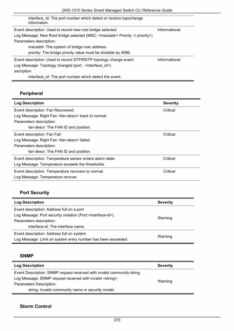
DXS-1210 Series Smart Managed Switch CLI Reference Guide
370
interface_id: The port number which detect or receive topochange information.
Event description: Used to record new root bridge selected. Log Message: New Root bridge selected (MAC: <macaddr> Priority :< priority>) Parameters description:
macaddr: The system of bridge mac address. priority: The bridge priority value must be divisible by 4096.
Informational
Event description: Used to record STP/RSTP topology change event. Log Message: Topology changed (port : <interface_id>) escription:
Interface_id: The port number which detect the event.
Informational
Peripheral
Log Description Severity
Event description: Fan Recovered. Log Message: Right Fan <fan-descr> back to normal. Parameters description:
fan-descr: The FAN ID and position.
Critical
Event description: Fan Fail Log Message: Right Fan <fan-descr> failed. Parameters description:
fan-descr: The FAN ID and position.
Critical
Event description: Temperature sensor enters alarm state. Log Message: Temperature exceeds the thresholds.
Critical
Event description: Temperature recovers to normal. Log Message: Temperature recover.
Critical
Port Security
Log Description Severity
Event description: Address full on a port Log Message: Port security violation (Port:<interface-id>). Parameters description:
interface-id: The interface name.
Warning
Event description: Address full on system Log Message: Limit on system entry number has been exceeded.
Warning
SNMP
Log Description Severity
Event Description: SNMP request received with invalid community string Log Message: SNMP request received with invalid <string>. Parameters Description:
string: Invalid community name or security model.
Warning
Storm Control

DXS-1210 Series Smart Managed Switch CLI Reference Guide
371
Log Description Severity
Event description: Storm occurrence. Log Message: <broadcast | multicast | unicast> storm is occurring on <interface-id>. Parameters description:
broadcast: Storm is resulted by broadcast packets(DA = FF:FF:FF:FF:FF:FF). multicast: Storm is resulted by multicast packets, including unknown L2 multicast, known L2 multicast, unknown IP multicast and known IP multicast. unicast: Storm is resulted by unicast packets, including both known and unknown unicast packets interface-id: The interface ID on which a storm is occurring.
Warning
Event description: Port shut down due to a packet storm Log Message: <interface-id> is currently shutdown due to the <broadcast | multicast | unicast> storm. Parameters description:
interface-id: The interface ID on which is error-disabled by storm. broadcast: The interface is disabled by broadcast storm. multicast: The interface is disabled by multicast storm. unicast: The interface is disabled by unicast storm (including both known and unknown unicast packets).
Warning
Telnet
Log Description Severity
Event description: Successful login through Telnet.
Log Message: Successful login through Telnet (User: <username>, IP: <ipaddr>)
Parameters description:
ipaddr: The IP address of telnet client.
username: the user name that used to login telnet server.
Informational
Event description: Login failed through Telnet.
Log Message: Login failed through Telnet (IP: <ipaddr>)
Parameters description:
ipaddr: The IP address of telnet client.
Warning
Event description: Logout through Telnet.
Log Message: Logout through Telnet (IP: <ipaddr>)
Parameters description:
ipaddr: The IP address of telnet client.
Informational
Event description: Telnet session timed out.
Log Message: Telnet session timed out (IP: <ipaddr>).
Parameters description:
ipaddr: The IP address of telnet client.
Informational
Web

DXS-1210 Series Smart Managed Switch CLI Reference Guide
372
Log Description Severity
Event description: Successful login through Web. Log Message: Successful login through Web (IP: <ipaddr>). Parameters description:
ipaddr: The IP address of HTTP client.
Informational
Event description: Login failed through Web. Log Message: Login failed through Web (IP: <ipaddr>). Parameters description:
ipaddr: The IP address of HTTP client.
Warning
Event description: Logout through Web. Log Message: Logout through Web (IP: <ipaddr>). Parameters description:
ipaddr: The IP address of HTTP client.
Informational
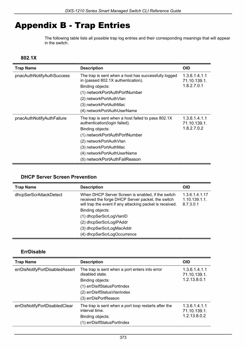
DXS-1210 Series Smart Managed Switch CLI Reference Guide
373
Appendix B - Trap Entries The following table lists all possible trap log entries and their corresponding meanings that will appear in the switch.
802.1X
Trap Name Description OID
pnacAuthNotifyAuthSuccess The trap is sent when a host has successfully logged in (passed 802.1X authentication). Binding objects: (1) networkPortAuthPortNumber (2) networkPortAuthVlan (3) networkPortAuthMac (4) networkPortAuthUserName
1.3.6.1.4.1.171.10.139.1.1.8.2.7.0.1
pnacAuthNotifyAuthFailure The trap is sent when a host failed to pass 802.1X authentication(login failed). Binding objects: (1) networkPortAuthPortNumber (2) networkPortAuthVlan (3) networkPortAuthMac (4) networkPortAuthUserName (5) networkPortAuthFailReason
1.3.6.1.4.1.171.10.139.1.1.8.2.7.0.2
DHCP Server Screen Prevention
Trap Name Description OID
dhcpSerScrAttackDetect When DHCP Server Screen is enabled, if the switch received the forge DHCP Server packet, the switch will trap the event if any attacking packet is received. Binding objects: (1) dhcpSerScrLogVlanID (2) dhcpSerScrLogIPAddr (3) dhcpSerScrLogMacAddr (4) dhcpSerScrLogOccurrence
1.3.6.1.4.1.171.10.139.1.1.8.7.3.0.1
ErrDisable
Trap Name Description OID
errDisNotifyPortDisabledAssert The trap is sent when a port enters into error disabled state. Binding objects: (1) errDisIfStatusPortIndex (2) errDisIfStatusVlanIndex (3) errDisPortReason
1.3.6.1.4.1.171.10.139.1.1.2.13.8.0.1
errDisNotifyPortDisabledClear The trap is sent when a port loop restarts after the interval time. Binding objects: (1) errDisIfStatusPortIndex
1.3.6.1.4.1.171.10.139.1.1.2.13.8.0.2
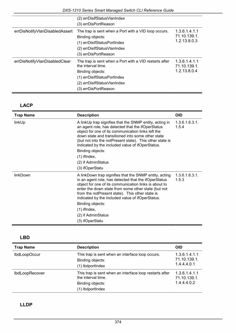
DXS-1210 Series Smart Managed Switch CLI Reference Guide
374
(2) errDisIfStatusVlanIndex (3) errDisPortReason
errDisNotifyVlanDisabledAssert The trap is sent when a Port with a VID loop occurs. Binding objects: (1) errDisIfStatusPortIndex (2) errDisIfStatusVlanIndex (3) errDisPortReason
1.3.6.1.4.1.171.10.139.1.1.2.13.8.0.3
errDisNotifyVlanDisabledClear The trap is sent when a Port with a VID restarts after the interval time. Binding objects: (1) errDisIfStatusPortIndex (2) errDisIfStatusVlanIndex (3) errDisPortReason
1.3.6.1.4.1.171.10.139.1.1.2.13.8.0.4
LACP
Trap Name Description OID
linkUp A linkUp trap signifies that the SNMP entity, acting in an agent role, has detected that the ifOperStatus object for one of its communication links left the down state and transitioned into some other state (but not into the notPresent state). This other state is indicated by the included value of ifOperStatus. Binding objects: (1) ifIndex, (2) if AdminStatus (3) ifOperStatu
1.3.6.1.6.3.1.1.5.4
linkDown A linkDown trap signifies that the SNMP entity, acting in an agent role, has detected that the ifOperStatus object for one of its communication links is about to enter the down state from some other state (but not from the notPresent state). This other state is indicated by the included value of ifOperStatus. Binding objects: (1) ifIndex, (2) if AdminStatus (3) ifOperStatu
1.3.6.1.6.3.1.1.5.3
LBD
Trap Name Description OID
lbdLoopOccur
This trap is sent when an interface loop occurs. Binding objects: (1) lbdportIndex
1.3.6.1.4.1.171.10.139.1.1.4.4.4.0.1
lbdLoopRecover This trap is sent when an interface loop restarts after the interval time. Binding objects: (1) lbdportIndex
1.3.6.1.4.1.171.10.139.1.1.4.4.4.0.2
LLDP
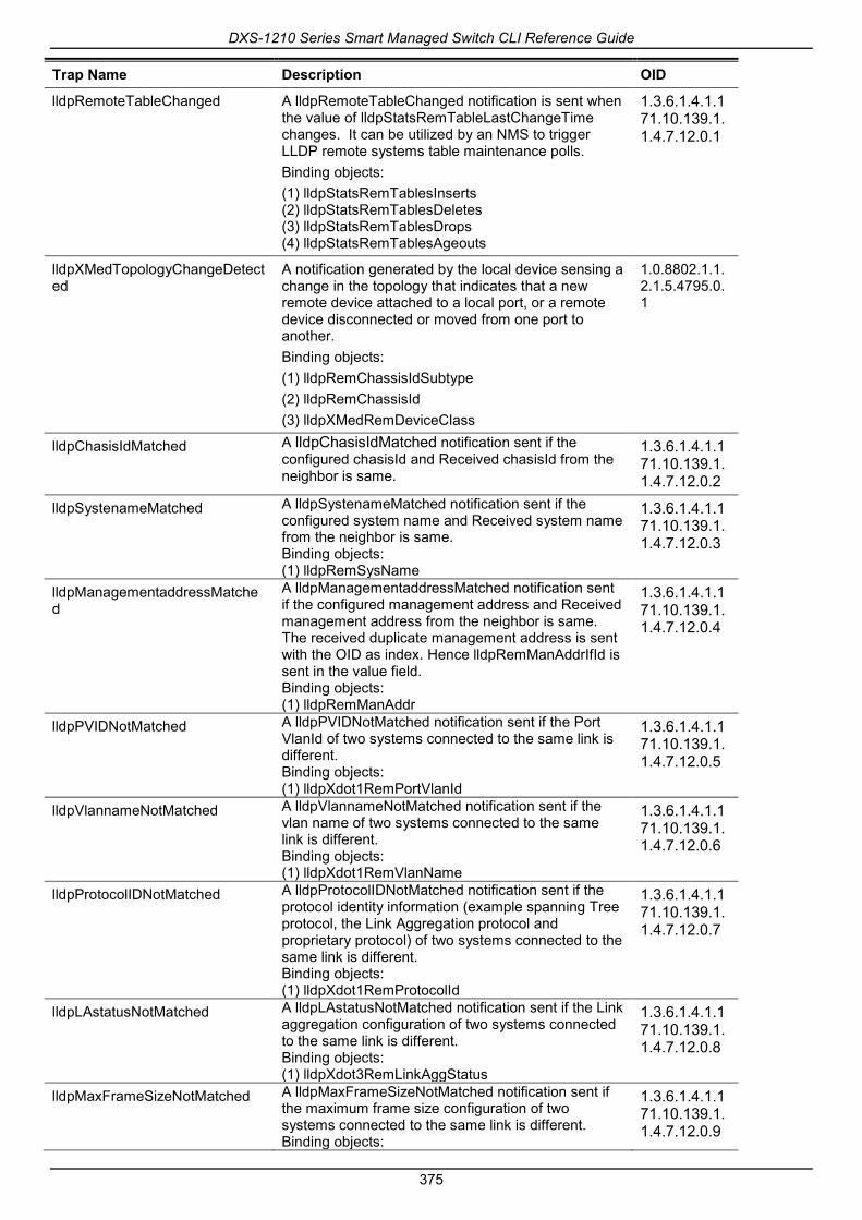
DXS-1210 Series Smart Managed Switch CLI Reference Guide
375
Trap Name Description OID
lldpRemoteTableChanged A lldpRemoteTableChanged notification is sent when the value of lldpStatsRemTableLastChangeTime changes. It can be utilized by an NMS to trigger LLDP remote systems table maintenance polls. Binding objects: (1) lldpStatsRemTablesInserts (2) lldpStatsRemTablesDeletes (3) lldpStatsRemTablesDrops (4) lldpStatsRemTablesAgeouts
1.3.6.1.4.1.171.10.139.1.1.4.7.12.0.1
lldpXMedTopologyChangeDetected
A notification generated by the local device sensing a change in the topology that indicates that a new remote device attached to a local port, or a remote device disconnected or moved from one port to another. Binding objects: (1) lldpRemChassisIdSubtype (2) lldpRemChassisId (3) lldpXMedRemDeviceClass
1.0.8802.1.1.2.1.5.4795.0.1
lldpChasisIdMatched A lldpChasisIdMatched notification sent if the configured chasisId and Received chasisId from the neighbor is same.
1.3.6.1.4.1.171.10.139.1.1.4.7.12.0.2
lldpSystenameMatched A lldpSystenameMatched notification sent if the configured system name and Received system name from the neighbor is same. Binding objects: (1) lldpRemSysName
1.3.6.1.4.1.171.10.139.1.1.4.7.12.0.3
lldpManagementaddressMatched
A lldpManagementaddressMatched notification sent if the configured management address and Received management address from the neighbor is same. The received duplicate management address is sent with the OID as index. Hence lldpRemManAddrIfId is sent in the value field. Binding objects: (1) lldpRemManAddr
1.3.6.1.4.1.171.10.139.1.1.4.7.12.0.4
lldpPVIDNotMatched A lldpPVIDNotMatched notification sent if the Port VlanId of two systems connected to the same link is different. Binding objects: (1) lldpXdot1RemPortVlanId
1.3.6.1.4.1.171.10.139.1.1.4.7.12.0.5
lldpVlannameNotMatched A lldpVlannameNotMatched notification sent if the vlan name of two systems connected to the same link is different. Binding objects: (1) lldpXdot1RemVlanName
1.3.6.1.4.1.171.10.139.1.1.4.7.12.0.6
lldpProtocolIDNotMatched A lldpProtocolIDNotMatched notification sent if the protocol identity information (example spanning Tree protocol, the Link Aggregation protocol and proprietary protocol) of two systems connected to the same link is different. Binding objects: (1) lldpXdot1RemProtocolId
1.3.6.1.4.1.171.10.139.1.1.4.7.12.0.7
lldpLAstatusNotMatched A lldpLAstatusNotMatched notification sent if the Link aggregation configuration of two systems connected to the same link is different. Binding objects: (1) lldpXdot3RemLinkAggStatus
1.3.6.1.4.1.171.10.139.1.1.4.7.12.0.8
lldpMaxFrameSizeNotMatched A lldpMaxFrameSizeNotMatched notification sent if the maximum frame size configuration of two systems connected to the same link is different. Binding objects:
1.3.6.1.4.1.171.10.139.1.1.4.7.12.0.9

DXS-1210 Series Smart Managed Switch CLI Reference Guide
376
(1) lldpXdot3RemMaxFrameSize lldpMAUTypeNotMatched A lldpMAUTypeNotMatched notification sent if the
Operational MauType of the two systems connected to the same link is different. Binding objects: (1) lldpXdot3RemPortOperMauType
1.3.6.1.4.1.171.10.139.1.1.4.7.12.0.10
MSTP
Trap Name Description OID
stpNewRootTrap The newRoot trap indicates that the sending agent hasbecome the new root of the Spanning Tree; the trap issent by a bridge soon after its election as the newroot, e.g., upon expiration of the Topology Change Timer,immediately subsequent to its election. Implementationof this trap is optional. Binding objects: (1) deviceInfoMACAddress (2) mstMstiBridgeRegionalRoot
1.3.6.1.4.1.171.10.139.1.1.4.3.6.0.1
stpTopologyChgTrap A topologyChange trap is sent by a bridge when any ofits configured ports transitions from the Learning stateto the Forwarding state, or from the Forwarding state tothe Blocking state.The trap is not sent if a newRoottrap is sent for the sametransition. Implementation ofthis trap is optional Binding objects: (1) deviceInfoMACAddress (2) mstMstiTopChanges
1.3.6.1.4.1.171.10.139.1.1.4.3.6.0.2
Peripheral
Trap Name Description OID
envTrapFanFailed Fan failed. Binding objects: (1) environmentFanId
1.3.6.1.4.1.171.10.139.1.1.2.2.6.0.1
envTrapFanRecover Fan recover. Binding objects: (1) environmentFanId
1.3.6.1.4.1.171.10.139.1.1.2.2.6.0.2
envTrapTemperatureExceed Temperature exceeds the thresholds. Binding objects: (1) environmentTempCurrent
1.3.6.1.4.1.171.10.139.1.1.2.2.6.0.3
envTrapTemperatureRecover Temperature recover. Binding objects: (1) environmentTempCurrent
1.3.6.1.4.1.171.10.139.1.1.2.2.6.0.4
Port
Trap Name Description OID
linkUp A notification is generated when port linkup. Binding objects: (1) ifIndex (2) if AdminStatus
1.3.6.1.6.3.1.1.5.4

DXS-1210 Series Smart Managed Switch CLI Reference Guide
377
(3) ifOperStatu
linkDown A notification is generated when port linkdown. Binding objects: (1) ifIndex (2) if AdminStatus (3) ifOperStatu
1.3.6.1.6.3.1.1.5.3
Port Security
Trap Name Description OID
portSecurityVioAction When the port security trap is enabled, new MAC addresses that violate the pre-defined port security configuration will trigger trap messages to be sent out. Binding objects: (1) portSecurityPort (2) portSecurityVioCount
1.3.6.1.4.1.171.10.139.1.1.8.1.2.1.1.4
RMON
Trap Name Description OID
risingAlarm The SNMP trap that is generated when an alarm entry crosses its rising threshold and generates an event that is configured for sending SNMP traps. Binding objects: (1)alarmIndex (2)eventDescription (3)alarmVariable (4)alarmSampleType (5) alarmValue (6) alarmRisingThreshold
1.3.6.1.2.1.16.0.1
fallingAlarm The SNMP trap that is generated when an alarm entry crosses its falling threshold and generates an event that is configured for sending SNMP traps. Binding objects: (1)alarmIndex (2)eventDescription (3) alarmVariable (4)alarmSampleType (5)alarmValue (6) alarmFallingThreshold
1.3.6.1.2.1.16.0.2
Start
Trap Name Description OID
coldStart A coldStart trap signifies that the SNMPv2 entity, acting in an agent role, is reinitializing itself and that itsconfiguration may have been altered.
1.3.6.1.6.3.1.1.5.1
warmStart A warmStart trap signifies that the SNMPv2 entity, acting in an agent role, is reinitializing itself such that itsconfiguration is unaltered.
1.3.6.1.6.3.1.1.5.2

DXS-1210 Series Smart Managed Switch CLI Reference Guide
378
Storm Control
Trap Name Description OID
stormCtrlTrapsStormOccur This trap is sent when storm is occurred or detected. Binding objects: (1) stormCtrlIndex
1.3.6.1.4.1.171.10.139.1.1.8.16.1.1.6.0.1
stormCtrlTrapsStormClear This trap is sent when port storm is cleared. Binding objects: (1) stormCtrlIndex
1.3.6.1.4.1.171.10.139.1.1.8.16.1.1.6.0.2

DXS-1210 Series Smart Managed Switch CLI Reference Guide
379
Appendix C - RADIUS Attributes Assignment The RADIUS Attributes Assignment on the DXS-1210 is used in the following modules: Console, Telnet, SSH, Web, 802.1X, MAC-based Access Control, JWAC, and WAC.
The description that follows explains the following RADIUS Attributes Assignment types:
• Ingress/Egress Bandwidth
• 802.1p Default Priority
• VLAN
To assign the Ingress/Egress Bandwidth by the RADIUS server, the proper parameters should be configured on the RADIUS Server. The table below shows the parameters for bandwidth.
The parameters of the Vendor-Specific attributes are:
Vendor-Specific Attribute Description Value Usage
Vendor-ID Defines the vendor. 171 (DLINK) Required
Vendor-Type Defines the attribute. 2 (for ingress bandwidth) 3 (for egress bandwidth)
Required
Attribute-Specific Field Used to assign the bandwidth of a port.
Unit (Kbits) Required
If the user has configured the bandwidth attribute of the RADIUS server (for example, ingress bandwidth 1000Kbps), and 802.1X authentication is successful, the device will assign the bandwidth (according to the RADIUS server) to the port. However, if the user does not configure the bandwidth attribute and authenticates successfully, the device will not assign any bandwidth to the port. If the bandwidth attribute is configured on the RADIUS server with a value of “0”, the effective bandwidth will be set “no_limited”, and if the bandwidth is configured less than “0” or greater than maximum supported value, the bandwidth will be ignored.
To assign the 802.1p Default Priority by the RADIUS server, the proper parameters should be configured on the RADIUS server. The table below shows the parameters for 802.1p default priority.
The parameters of the Vendor-Specific attributes are:
Vendor-Specific Attribute Description Value Usage
Vendor-ID Defines the vendor. 171 (DLINK) Required
Vendor-Type Defines the attribute. 4 Required
Attribute-Specific Field Used to assign the 802.1p default priority of the port.
0 to 7 Required
If the user has configured the 802.1p priority attribute of the RADIUS server (for example, priority 7) and 802.1X authentication is successful, the device will assign the 802.1p default priority (according to the RADIUS server) to the port. However, if the user does not configure the priority attribute and authenticates successfully, the device will not assign a priority to this port. If the priority attribute is configured on the RADIUS server is a value out of range (>7), it will not be set to the device.

DXS-1210 Series Smart Managed Switch CLI Reference Guide
380
To assign the VLAN by the RADIUS server, the proper parameters should be configured on the RADIUS server. To use VLAN assignment, RFC3580 defines the following tunnel attributes in RADIUS packets.
The table below shows the parameters for a VLAN:
RADIUS Tunnel Attribute Description Value Usage
Tunnel-Type This attribute indicates the tunneling protocol(s) to be used (in the case of a tunnel initiator) or the tunneling protocol in use (in the case of a tunnel terminator).
13 (VLAN) Required
Tunnel-Medium-Type This attribute indicates the transport medium being used.
6 (802) Required
Tunnel-Private-Group-ID This attribute indicates group ID for a particular tunneled session.
ASCII (VID) Required

DXS-1210 Series Smart Managed Switch CLI Reference Guide
381
Appendix D - IETF RADIUS Attributes Support Remote Authentication Dial-In User Service (RADIUS) attributes carry specific authentication, authorization, information and configuration details for the request and reply. This appendix lists the RADIUS attributes currently supported by the switch.
RADIUS attributes are supported by the IETF standard and Vendor-Specific Attribute (VSA). VSA allows the vendor to create an additionally owned RADIUS attribute. For more information about D-Link VSA, refer to the RADIUS Attributes Assignment Appendix.
IETF standard RADIUS attributes are defined in the RFC 2865 Remote Authentication Dial-In User Service (RADIUS), RFC 2866 RADIUS Accounting, RFC 2868 RADIUS Attributes for Tunnel Protocol Support, and RFC 2869 RADIUS Extensions.
The following table lists the IETF RADIUS attributes supported by the D-Link switch.
RADIUS Authentication Attributes:
Number IETF Attribute
1 User-Name
2 User-Password
18 Reply-Message
24 State
26 Vendor-Specific
27 Session-Timeout
29 Termination-Action
64 Tunnel-Type
65 Tunnel-Medium-Type
79 EAP-Message
80 Message-Authenticator
81 Tunnel-Private-Group-ID

DXS-1210 Series Smart Managed Switch CLI Reference Guide
382
Appendix E - ERPS Information Only hardware-based ERPS (external PHY) supports the fast link drop interrupt feature with a recovery time of 50ms.
Model Name ERPS Port 1 to 8 Port 9 to 12
DXS-1210-12TC Hardware-based
Software-based V V
Model Name ERPS Port 1 to 8 Port 9 to 12
DXS-1210-12SC Hardware-based
Software-based V V
Model Name ERPS Port 1 to 8 Port 9 to 10
DXS-1210-10TS Hardware-based
Software-based V V
Model Name ERPS Port 1 to 8 Port 9 to 16
DXS-1210-16TC Hardware-based
Software-based V V