DX Mechanical Digital Door Locks Service...
24
DX Mechanical Digital Door Locks Service Manual ASSA ABLOY, the global leader in door opening solutions
Transcript of DX Mechanical Digital Door Locks Service...
DX Mechanical Digital Door Locks Service Manual
ASSA ABLOY, the global leader in door opening solutions

Service Manual: This manual contains a complete listing of parts and assemblies for the DX Series Mechanical Digital Locks supplied by ASSA ABLOY Australia. Exploded views are included along with parts list for ordering of replacement components.
ASSA ABLOY Australia reserves the right to make changes in design or specifications, or to make additions or improvements to their product without incurring any obligation to incorporate these amendments in product previously manufactured.
ASSA ABLOY Australia are not responsible for additions or alterations made to their product by others.
Maintenance: Cleaning: Care should be taken during construction/refurbishment to ensure that paint, thinners, mortar or cement splashes are carefully removed from locks, furniture and hardware. Removal of these splashes with strong cleaning agents or scourers should be avoided.
Dirt and grime should be regularly removed with a soft damp cloth. A solution of mild soap and water may be required. During cleaning, care should be taken to prevent cleaning solution from entering the cylinder keyway. Surfaces should be dried.
Introduction

Contents
Setting a New Code 6
530 DX Mechanical Digital Locks 8
530 DX Mechanical Digital Locks – 2 Pads 9
002 DX Mechanical Digital Locks 10
Synergy 3572 DX Mechanical Digital Locks 11
Synergy 3572 DX Mechanical Digital Locks - Key Override 12
Synergy 3582 DX Mechanical Digital Locks 13
Mounting Instructions 14
The global leader in door opening solutions
ASSA ABLOY Australia Limited, 235 Huntingdale Rd, Oakleigh, VIC 3166 ABN 90 086 451 907 ©2012
4
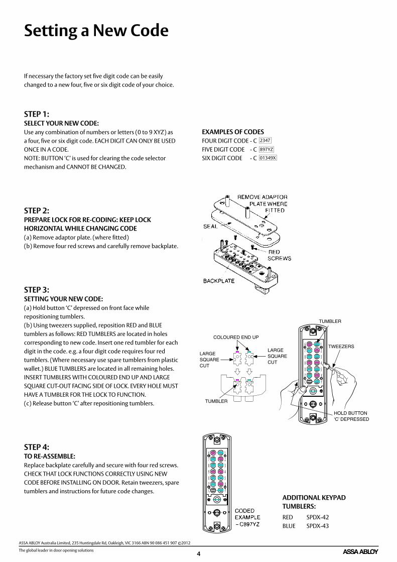
Setting a New Code
If necessary the factory set five digit code can be easily changed to a new four, five or six digit code of your choice.
STEP 1:SELECT YOUR NEW CODE: Use any combination of numbers or letters (0 to 9 XYZ) as a four, five or six digit code. EACH DIGIT CAN ONLY BE USED ONCE IN A CODE. NOTE: BUTTON ‘C’ is used for clearing the code selector mechanism and CANNOT BE CHANGED.
STEP 2:PREPARE LOCK FOR RE-CODING: KEEP LOCK HORIZONTAL WHILE CHANGING CODE (a) Remove adaptor plate. (where fitted) (b) Remove four red screws and carefully remove backplate.
STEP 3:SETTING YOUR NEW CODE: (a) Hold button ‘C’ depressed on front face while repositioning tumblers. (b) Using tweezers supplied, reposition RED and BLUE tumblers as follows: RED TUMBLERS are located in holes corresponding to new code. Insert one red tumbler for each digit in the code. e.g. a four digit code requires four red tumblers. (Where necessary use spare tumblers from plastic wallet.) BLUE TUMBLERS are located in all remaining holes. INSERT TUMBLERS WITH COLOURED END UP AND LARGE SQUARE CUT-OUT FACING SIDE OF LOCK. EVERY HOLE MUST HAVE A TUMBLER FOR THE LOCK TO FUNCTION. (c) Release button ‘C’ after repositioning tumblers.
STEP 4:TO RE-ASSEMBLE: Replace backplate carefully and secure with four red screws. CHECK THAT LOCK FUNCTIONS CORRECTLY USING NEW CODE BEFORE INSTALLING ON DOOR. Retain tweezers, spare tumblers and instructions for future code changes.
EXAMPLES OF CODES FOUR DIGIT CODE - C FIVE DIGIT CODE - C SIX DIGIT CODE - C
2347
897YZ
01349X
ADDITIONAL KEYPAD TUMBLERS: RED SPDX-42 BLUE SPDX-43
89
Z
12345
YX
C
67
0 KEYLESSKEY
89
Z
12345
YX
C
67
08
123
67
RED BLUE
LARGE SQUARE CUT
LARGE SQUARE CUT
TUMBLER
COLOURED END UP
89
Z
12345
YX
C
67
0
89
Z
12345
YX
C
67
0
89
Z
12345
YX
C
67
0
89
Z
12345
YX
C
67
0
TUMBLER
TWEEZERS
HOLD BUTTON ‘C’ DEPRESSED

DX M
echa
nica
l Dig
ital L
ocks

6
530
DX
Mec
hani
cal D
igita
l Loc
ks53
0 D
X M
echa
nica
l Dig
ital L
ocks
Ord
erab
le L
ocks
530D
XSC
DX
Dig
ital 5
30 L
atch
Trad
e Pa
ck
530D
XPB
DX
Dig
ital 5
30 L
atch
Trad
e Pa
ck
530D
XSCD
PD
X D
igita
l 530
Lat
ch D
ispl
ay P
ack
530D
XPBD
PD
X D
igita
l 530
Lat
ch D
ispl
ay P
ack
Fixi
ng sc
rew
Doo
r thi
ckne
ss:
33 to
45m
m: S
P930
-108
ZP46
to 6
5mm
: SP9
30-2
08ZP
Latc
h an
d St
rike
Kits
60m
m b
acks
et: 5
30-1
2SC
(def
ault)
70m
m b
acks
et: 5
30-2
22SC
127m
m b
acks
et: 5
30-2
25SC
Inte
rnal
pla
te &
gas
ket
SPD
X-30
SC
Code
pad
and
gas
ket
SPD
X-20
SC
Spin
dle
Doo
r thi
ckne
ss:
33 to
45m
m: S
P100
00-1
27ZP
(def
ault)
46 to
55m
m: S
P100
00-6
27ZP
56 to
65m
m: S
P100
00-7
27ZP

7
530
DX
Mec
hani
cal D
igita
l Loc
ks -
Two
Pads
Fixi
ng S
crew
s Doo
r thi
ckne
ss:
33
to 4
5mm
: SP9
30-1
08ZP
46 to
65m
m: S
P930
-208
ZP
Latc
h an
d St
rike
Kits
60m
m b
acks
et: 5
30-1
2SC
(def
ault)
70m
m b
acks
et: 5
30-2
22SC
127m
m b
acks
et: 5
30-2
25SC
Spin
dles
Doo
r thi
ckne
ss:
33 to
45m
m: S
P100
00-1
127Z
P (d
efau
lt)
46 to
55m
m: S
P100
00-1
227Z
P
Exte
rnal
Cod
e Pa
d &
gas
ket
SPD
X-20
SC
Inte
rnal
Cod
e Pa
d &
gas
ket
SPD
X-22
0SC
530
DX
Mec
hani
cal D
igita
l Loc
ks –
2 P
ads
Ord
erab
le L
ocks
530D
XSC/
PAD
SX2
DX
Dig
ital 5
30 L
atch
Trad
e Pa
ck 2
Pad
s
530D
XPB/
PAD
SX2
DX
Dig
ital 5
30 L
atch
Trad
e Pa
ck 2
Pad
s

8
002
DX
Mec
hani
cal D
igita
l Loc
ks
Code
pad
& g
aske
t SP
DX-
50SC
002
DX
Mec
hani
cal D
igita
l Loc
ksO
rder
able
Loc
ks
002-
1KD
XSC
DX
Dig
ital 0
02 K
nob
Tim
ber S
trik
e Tr
ade
Pack
002-
3KD
XSC
DX
Dig
ital 0
02 K
nob
Met
al Fr
ame
Strik
e Tr
ade
Pack
002-
4KD
XSC
DX
Dig
ital 0
02 K
nob
Ope
n O
ut S
trik
e Tr
ade
Pack
002-
1LD
XSC
DX
Dig
ital 0
02 L
ever
Tim
ber S
trik
e Tr
ade
Pack
002-
3LD
XSC
DX
Dig
ital 0
02 L
ever
Met
al Fr
ame
Strik
e Tr
ade
Pack
002-
4LD
XSP
DX
Dig
ital 0
02 L
ever
Ope
n O
ut S
trik
e Tr
ade
Pack
002-
1KD
XSCD
PD
X D
igita
l 002
Kno
b Ti
mbe
r Str
ike
Dis
play
Pac
k
Mou
ntin
g pl
ate
SP
DX-
520
Spin
dle
SP10
000-
138Z
P
Mou
ntin
g pl
ate
scre
w
SP10
000-
134Z
P
Code
pad
fixi
ng sc
rew
SP
1000
0-10
8ZP Sc
rew
cup
was
her
SP10
000-
107S
C
002
Vari
atio
nsKn
ob ti
mbe
r tim
ber o
pen
in:
002-
1K1S
CKn
ob m
etal
fram
e op
en in
: 00
2-3K
1SC
Knob
ope
n ou
t: 0
02-4
K1SC
Leve
r tim
ber f
ram
e op
en in
: 00
2-1L
1SC
Leve
r met
al fr
ame
open
in:
002-
3L1S
CLe
ver o
pen
out:
002
-4L1
SC

9
Syne
rgy
3572
DX
Mec
hani
cal D
igita
l Loc
ks
3572
DX
Mec
hani
cal D
igita
l Loc
ksO
rder
able
Loc
ks
3572
DXL
SCD
X D
igita
l 357
2 60
mm
Bac
kset
Lef
t Han
d
3572
DXR
SCD
X D
igita
l 357
2 60
mm
Bac
kset
Rig
ht H
and
4572
DXL
SCD
X D
igita
l 357
2 89
mm
Bac
kset
Lef
t Han
d
4572
DXR
SCD
X D
igita
l 357
2 89
mm
Bac
kset
Rig
ht H
and
5572
DXL
SCD
X D
igita
l 357
2 12
7mm
Bac
kset
Lef
t Han
d
5572
DXR
SCD
X D
igita
l 357
2 12
7mm
Bac
kset
Rig
ht H
and
Code
Pad
& g
aske
t SP
DX-
50SC
Mou
ntin
g pl
ate
SPD
X-32
4
Mou
ntin
g Pl
ate
Scre
w
SP10
000-
134Z
P
Scre
w c
up w
ashe
r SP
1000
0-10
7SC
Fixi
ng S
crew
sSP
1800
-408
ZP (5
0MM
)SR
WM
4-65
SS (6
5MM
)
Adap
tor
SP35
70-5
050
Lock
3572
SC
For c
ompo
nent
s tha
t rel
ate
spec
ifica
lly
to th
e m
ortic
e lo
ck re
fer t
o th
e Sy
nerg
y Se
ries S
ervi
ce M
anua
l for
Det
ails
.
1800
/280
0 in
tern
al fu
rnitu
re p
late
re
quire
d to
com
plet
e as
sem
bly
- or
dere
d se
para
tely.
Furn
iture
Fix
ing
Scre
w
SPD
S806
/32A
ZP
Spin
dle
SP10
000-
138Z
P
10
3572
DX
Key
Ove
rrid
e M
echa
nica
l Dig
ital L
ocks
Ord
erab
le L
ocks
3572
DXK
OLS
CD
X D
igita
l 357
2 60
mm
Bac
kset
Key
Ove
rrid
e Le
ft H
and
3572
DXK
ORS
CD
X D
igita
l 357
2 60
mm
Bac
kset
Key
Ove
rrid
e Ri
ght H
and
4572
DXK
OLS
CD
X D
igita
l 357
2 89
mm
Bac
kset
Key
Ove
rrid
e Le
ft H
and
4572
DXK
ORS
CD
X D
igita
l 357
2 89
mm
Bac
kset
Key
Ove
rrid
e Ri
ght H
and
5572
DXK
OLS
CD
X D
igita
l 357
2 12
7mm
Bac
kset
Key
Ove
rrid
e Le
ft H
and
5572
DXK
ORS
CD
X D
igita
l 357
2 12
7mm
Bac
kset
Key
Ove
rrid
e Ri
ght H
and
Syne
rgy
3572
DX
Mec
hani
cal
Dig
ital L
ocks
- Ke
y O
verr
ide
3572
DXK
OLS
CNCY
LD
X D
igita
l 357
2 60
mm
Bac
kset
Key
Ove
rrid
e Le
ft H
and
No
Cylin
der
3572
DXK
ORS
CNCY
LD
X D
igita
l 357
2 60
mm
Bac
kset
Key
Ove
rrid
e Ri
ght H
and
No
Cylin
der
4572
DXK
OLS
CNCY
LD
X D
igita
l 357
2 89
mm
Bac
kset
Key
Ove
rrid
e Le
ft H
and
No
Cylin
der
4572
DXK
ORS
CNCY
LD
X D
igita
l 357
2 89
mm
Bac
kset
Key
Ove
rrid
e Ri
ght H
and
No
Cylin
der
5572
DXK
OLS
CNCY
LD
X D
igita
l 357
2 12
7mm
Bac
kset
Key
Ove
rrid
e Le
ft H
and
No
Cylin
der
5572
DXK
ORS
CNCY
LD
X D
igita
l 357
2 12
7mm
Bac
kset
Key
Ove
rrid
e Ri
ght H
and
No
Cylin
der
Mou
ntin
g Pl
ate
Ac
cess
ory
Pack
et
SP35
77-5
619
Spin
dle
SP10
000-
138Z
P
Low
er c
ylin
der
asse
mbl
y 57
7-2S
C
Fixi
ng sc
rew
sSP
1800
-408
ZP (5
0MM
)SR
WM
4-65
SS (6
5MM
)
Scre
w c
up w
ashe
r SP
1000
0-10
7SC
Key
over
ride
cyl
inde
r m
ount
ing
plat
e SP
DX-
524
Mou
ntin
g pl
ate
scre
w
SP10
000-
134Z
P
Mou
ntin
g pl
ate
SPD
X-32
4
Code
pad
& g
aske
t SP
DX-
50SC
Adap
tor
SP35
70-5
050
Lock
3572
SC
For c
ompo
nent
s tha
t rel
ate
spec
ifica
lly
to th
e m
ortic
e lo
ck re
fer t
o th
e Sy
nerg
y Se
ries S
ervi
ce M
anua
l for
Det
ails
.
1800
/280
0 in
tern
al fu
rnitu
re p
late
re
quire
d to
com
plet
e as
sem
bly
- or
dere
d se
para
tely.
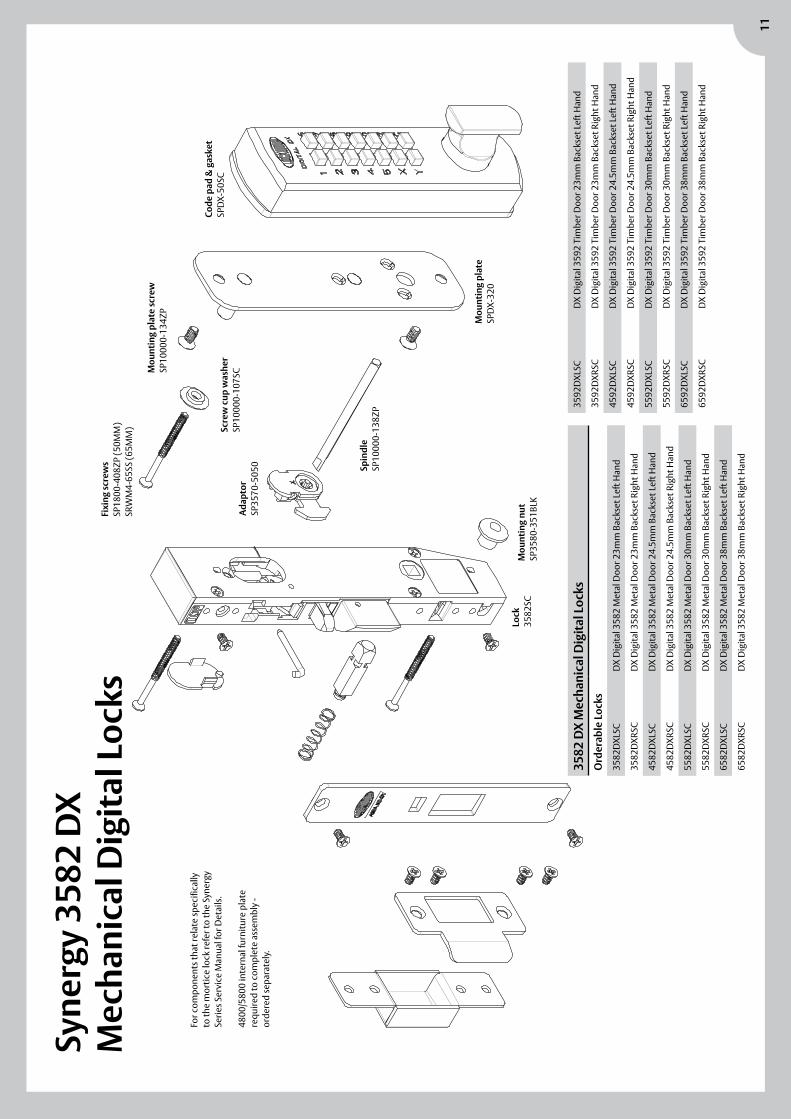
11
Syne
rgy
3582
DX
M
echa
nica
l Dig
ital L
ocks
3582
DX
Mec
hani
cal D
igita
l Loc
ksO
rder
able
Loc
ks
3582
DXL
SCD
X D
igita
l 358
2 M
etal
Doo
r 23m
m B
acks
et L
eft H
and
3582
DXR
SCD
X D
igita
l 358
2 M
etal
Doo
r 23m
m B
acks
et R
ight
Han
d
4582
DXL
SCD
X D
igita
l 358
2 M
etal
Doo
r 24.
5mm
Bac
kset
Lef
t Han
d
4582
DXR
SCD
X D
igita
l 358
2 M
etal
Doo
r 24.
5mm
Bac
kset
Rig
ht H
and
5582
DXL
SCD
X D
igita
l 358
2 M
etal
Doo
r 30m
m B
acks
et L
eft H
and
5582
DXR
SCD
X D
igita
l 358
2 M
etal
Doo
r 30m
m B
acks
et R
ight
Han
d
6582
DXL
SCD
X D
igita
l 358
2 M
etal
Doo
r 38m
m B
acks
et L
eft H
and
6582
DXR
SCD
X D
igita
l 358
2 M
etal
Doo
r 38m
m B
acks
et R
ight
Han
d
3592
DXL
SCD
X D
igita
l 359
2 Ti
mbe
r Doo
r 23m
m B
acks
et L
eft H
and
3592
DXR
SCD
X D
igita
l 359
2 Ti
mbe
r Doo
r 23m
m B
acks
et R
ight
Han
d
4592
DXL
SCD
X D
igita
l 359
2 Ti
mbe
r Doo
r 24.
5mm
Bac
kset
Lef
t Han
d
4592
DXR
SCD
X D
igita
l 359
2 Ti
mbe
r Doo
r 24.
5mm
Bac
kset
Rig
ht H
and
5592
DXL
SCD
X D
igita
l 359
2 Ti
mbe
r Doo
r 30m
m B
acks
et L
eft H
and
5592
DXR
SCD
X D
igita
l 359
2 Ti
mbe
r Doo
r 30m
m B
acks
et R
ight
Han
d
6592
DXL
SCD
X D
igita
l 359
2 Ti
mbe
r Doo
r 38m
m B
acks
et L
eft H
and
6592
DXR
SCD
X D
igita
l 359
2 Ti
mbe
r Doo
r 38m
m B
acks
et R
ight
Han
d
For c
ompo
nent
s tha
t rel
ate
spec
ifica
lly
to th
e m
ortic
e lo
ck re
fer t
o th
e Sy
nerg
y Se
ries S
ervi
ce M
anua
l for
Det
ails
.
4800
/580
0 in
tern
al fu
rnitu
re p
late
re
quire
d to
com
plet
e as
sem
bly
- or
dere
d se
para
tely.
Mou
ntin
g nu
t SP
3580
-351
BLK
Lock
3582
SC
Spin
dle
SP10
000-
138Z
P
Code
pad
& g
aske
t SP
DX-
50SC
Mou
ntin
g pl
ate
SPD
X-32
0
Mou
ntin
g pl
ate
scre
w
SP10
000-
134Z
P
Scre
w c
up w
ashe
r SP
1000
0-10
7SC
Fixi
ng sc
rew
s SP
1800
-408
ZP (5
0MM
)SR
WM
4-65
SS (6
5MM
)
Adap
tor
SP35
70-5
050

Mounting Instructionsand Templates

The global leader in door opening solutions
ASSA ABLOY Australia Limited, 235 Huntingdale Rd, Oakleigh, VIC 3166 ABN 90 086 451 907 ©2012
13
530 DX SERIESDIGITAL ENTRANCE SET
2. Install digital lock and interior furniture plate.
(a) Fit rubber seal to the back of the digital lock and interior furniture plate.(b) Insert blade end of spindle in vertical position into digital lock drive gear.(c) Install digital lock and interior furniture plate to door with both turn knobs in vertical position. NOTE: Ensure that spindle engages latch hub and interior furniture plate drive gear.(d) Secure using two metal thread mounting screws.
1000
0-22
1_30
621-
0504
Latchhub
Door
Latch
Latch mounting screws
Interior furnitureplate
Metal threadmounting screws Seal
Seal
Spindle
Digital lock
Latch mounting screws
Door
Latch
Seal
Seal
Door
Interior furnitureplate drive gear
lock drive gear
Blade endof spindle
Metal threadmounting screws
530 DX SERIESDIGITAL ENTRANCE SET
Strike
Jamb
Half door thickness
Latch mounting screws
3. Prepare jamb and install strike.
(a) Mark strike location on jamb edge directly opposite latch as shown.(b) Locate strike on jamb edge centrally about horizontal centreline with screw holes in strike on vertical centreline. Mark outline of strike and bolt hole onto jamb edge.(c) Mortice in the following sequence: 1. Bolt hole mortice 16mm ( ") deep. 2. Strike mortice 1.5mm ( ") deep.(d) Pre-drill 2.5mm ( ") to accept mounting screws and secure using woodscrews supplied.
58
116
332
3 PREPARE AND INSTALL
2 INSTALL LOCK
1
1. Prepare door and install latch.
(a) Mark and drill holes as shown on template.(b) Insert latch into hole in door edge and scribe around faceplate.(c) Mortice 4mm ( ") deep to accept latch faceplate.(d) Pre-drill 2.5mm ( ") to accept mounting screws and secure latch using woodscrews supplied.
532
332
Lock mounting position.This product is more convenient to operate at approximatelychest level, but door construction may restrict the mounting position.SOLID DOORS: Permit mounting at any height.HOLLOW CORE DOORS: Mounting may be restricted by thesize and position of the timber block within the door for lock mounting.
Note: For fire door applications, keypad must be fitted without rubber mounting pad.
FOLLOW INSTRUCTIONS CAREFULLY
INSTALL LOCKLOCK MOUNTING POSITION

The global leader in door opening solutions
ASSA ABLOY Australia Limited, 235 Huntingdale Rd, Oakleigh, VIC 3166 ABN 90 086 451 907 ©2012
14
DIGITAL DEADLOCKMOUNTING INSTRUCTIONS
OPTIONAL31mm Retrofit Strike 001-36533mm Packer plate 001-3254BLK
LOCK MOUNTING POSITION This product is more convenient to operate at approximately chest level, but doorconstruction may restrict the mounting position.SOLID DOORS : Permit mounting at any height.HOLLOW CORE DOORS : Mounting may be restricted by the size and position of the timberblock within the door for lock mounting.
FOLLOW INSTRUCTIONS CAREFULLY
5065
M 0
612
Anti-
Cloc
kwis
e O
peni
ng
Doo
r Te
mpl
ate
1. S
elec
t CLO
CKW
ISE
or A
NTI
-CLO
CKW
ISE
tem
plat
e to
suit
door
ope
ning
dire
ctio
n.2.
Pla
ce te
mpl
ate
on in
side
doo
r fa
ce a
t req
uire
d he
ight
from
fl
oor w
ith LI
NE
A p
ositi
oned
on
door
edg
e.3.
Mar
k an
d dr
ill h
oles
as
spec
ified
on
tem
plat
e.
Door Frame Strengthener Template
DRILL 2 HOLES5mm Dia x 63mm
DeepTEAR OFF
FOLD LINE
TEAR OFF
DRI
LL 4
HO
LES
3mm
Dia
x 2
5mm
D
eep
DRI
LL 3
2mm
Dia
HO
LE
DRI
LL H
OLE
FRO
M
BOTH
SID
ES O
F D
OO
R.
TO P
REVE
NT
SPLI
NTE
RIN
G O
F
DO
OR
FACE
THIS
WAY
UP
INSI
DE
60m
m B
ACKS
ET1. Select CLOCKWISE or ANTI-CLOCKWISE side of template
to suit door opening direction.2. Position template and prepare door as specified on template.
DRILL CYLINDER HOLE FROM BOTH SIDES OF DOOR.TO PREVENT SPLINTERING OF DOOR FACE.
LINE A
1. Rotate turn knob fully clockwise to HOLD BACK position. 2. Remove two case mounting screws from lock case.3. Take mounting plate out of lock case.
Mounting Plate
Lock Case
P.T.O.
USE
OTH
ER S
IDE
OF T
EMPL
ATE
FOR
CLO
CKW
ISE
DO
OR
DRI
LL H
OLE
10m
m
Template
JAMB
DOOR
LINE A
LOCK CASE
DOOR FRAMESTRENGTHENER
DOOR FRAMESTRENGTHENER
SCREWS (2)
CASEMOUNTINGSCREWS (2)
MOUNTING PLATESCREWS (4)
DIGITAL LOCK MOUNTINGSCREWS (2) FLAT HEAD
MOUNTING PLATEASSEMBLY
TIMBER JAMB
DOOR
DIGITALLOCK
SPINDLE
DIGITAL LOCKMOUNTING
SCREW
CUPWASHER
STRIKEMOUNTINGSCREWS (3)
STRIKE
1 PREPARE DOOR 2 PREPARE LOCK
FOR INWARD OPENING DOORS WITH TIMBER JAMB
LOCK MOUNTING POSITION

The global leader in door opening solutions
ASSA ABLOY Australia Limited, 235 Huntingdale Rd, Oakleigh, VIC 3166 ABN 90 086 451 907 ©2012
15
DIGITAL DEADLOCKMOUNTING INSTRUCTIONS
Door FrameStrengthener
Strike
JAMB
Door FrameStrengthener Template
1. Position strike on jamb directly opposite the lock case and mark outline of strike flange on jamb edge.
2. Mortice area for flange. Depth of flange mortice determines gap. Note : 3mm maximum gap between lock and installed strike.
3. Position door frame strengthener template in strike flange mortice as shown below.
4. WARNING: Care must be taken when drilling and affixing screws to jamb. Screws must NOT come in contact with electrical wires in jamb. Mark and drill holes as specified on template.
5. Install door frame strengthener and secure using two door frame strengthener screws.
6. Locate strike over door frame strengthener and secure using three strike mounting screws. Note : Pre-drill 3mm Dia x 25mm deep for woodscrews.
Clockwise
Opening
Door Tem
plate
1. Select CLOCKW
ISE or AN
TI-CLOCKW
ISE template
to suit door opening direction.2. Place tem
plate on inside door face at required height from
floor w
ith LIN
E A positioned
on door edge.3. M
ark and drill holes as specified on tem
plate.
Door Frame Strengthener Template
DRILL 2 HOLES5mm Dia x 63mm
Deep
TEAR
OFF
FOLD LINE
TEAR OFF
DRILL 4 H
OLES
3mm
D
ia x 25mm
D
eepD
RILL 32mm
Dia H
OLE D
RILL HO
LE FROM
BO
TH SID
ES OF D
OO
R. TO
PREVENT SPLIN
TERING
OF
D
OO
R FACE
THIS W
AYU
P
INSID
E
60mm
BACKSET
LINE A
USE O
THER SID
E OF TEM
PLATE FO
R ANTI-CLO
CKWISE D
OO
RD
RILL HO
LE10m
m
3mm Max.
5 INSTALL FRAME STRENGTHENER & STRIKE
1. Rotate lever fully clockwise to the HOLD BACK position.2. Ensure notch on hub is aligned with ‘V’ on mounting plate. Fit case body to mounting plate as shown.3. Lightly tap both front corners of case to ensure it is fully home on the mounting plate.4. Secure to mounting plate using the two case mounting screws.5. Test entire operation of lock BEFORE CLOSING THE DOOR.
4 INSTALL CASE
Case MountingScrews (2)
Mounting PlateScrews (4)
Digital Lock MountingScrews, Flat Head (2)
DOOR
Hub
Mounting Plate
CupWasher
Digital LockMounting
Screw
DO NOT OVER TIGHTEN DURING INSTALLATION
1. Fix MOUNTING PLATE to door with four woodscrews supplied.2. Align Notch on HUB with vee on mounting plate. 3. Insert and locate, blade end of spindle into hub from outside of door.
Mark and cut spindle to length. (19mm from Door Face).4. Insert spindle into digital lock drive gear with blade end facing out.5. Realign notch on hub with vee on mounting plate. Secure digital lock
with mounting screw through cup washer and into top hole. Cut screw if required. Ensure blade end of spindle engages in hub.
6. Place rear digital lock mounting screw through slot in hub and secure digital lock to door.
7. Rotate HUB 90 by entering code of Digital Lock and turning knob. Hold in position and secure second screw.
3 INSTALL DIGITAL LOCK & MTG PLATE
Spindle
19mm

The global leader in door opening solutions
ASSA ABLOY Australia Limited, 235 Huntingdale Rd, Oakleigh, VIC 3166 ABN 90 086 451 907 ©2012
16
3570 DX SERIES MECHANICAL DIGITAL LOCKSMOUNTING INSTRUCTIONS

The global leader in door opening solutions
ASSA ABLOY Australia Limited, 235 Huntingdale Rd, Oakleigh, VIC 3166 ABN 90 086 451 907 ©2012
17
3570 DX SERIES MECHANICAL DIGITAL LOCKSMOUNTING INSTRUCTIONS

The global leader in door opening solutions
ASSA ABLOY Australia Limited, 235 Huntingdale Rd, Oakleigh, VIC 3166 ABN 90 086 451 907 ©2012
18
3570 DX SERIES KEY OVERRIDE MECHANICAL DIGITAL LOCKSMOUNTING INSTRUCTIONS

The global leader in door opening solutions
ASSA ABLOY Australia Limited, 235 Huntingdale Rd, Oakleigh, VIC 3166 ABN 90 086 451 907 ©2012
19
3570 DX SERIES KEY OVERRIDE MECHANICAL DIGITAL LOCKSMOUNTING INSTRUCTIONS

The global leader in door opening solutions
ASSA ABLOY Australia Limited, 235 Huntingdale Rd, Oakleigh, VIC 3166 ABN 90 086 451 907 ©2012
20
3580 SERIESMECHANICAL DIGITAL LOCKS FOR METAL DOORS
3580-621SN500 1296
All Lockwood 3580 Series Mechanical Digital Locks are to be mounted in accordance with these instructions.Important : Before drilling door ensure correct hand is being installed.NOTE: CASE DOES NOT need to be Opened, to change HAND
or FUNCTION of LOCK.
TYPE OF LOCK OPERATIONSSTANDARD
Opened from outside by entering correct code and rotating turn knob.On releasing turnknob the code is automatically cancelled. Open frominside by handle at all times.
HOLD BACK CYLINDER OPENED FROM OUTSIDE :By entering correct code and rotating turn knob. On releasing turn knobthe code is automatically cancelled. To apply HOLD - BACK insert keyinto interior cylinder and rotate one full turn, withdraw key.
OPENED FROM INSIDE :By handle at all times.
HAND OF LOCK BOLT1. Determine hand of lock required from hand of door chart.2. Rotate bolt head to suit latching direction.
HAND OF DOORACCORDINGTO ENGLISHPRACTICE
RIGHT - HAND DOOR LEFT - HAND DOOR
OUTSIDEDOOR OPENING
IN
OUTSIDEDOOR OPENING
OUT
OUTSIDEDOOR OPENING
OUT
OUTSIDEDOOR OPENING
IN
3580 SERIES MECHANICAL DIGITAL LOCKSFOR METAL DOORSLOCK UP WITH LOCKWOOD
TM
1 PREPARE LOCK
3. Place template in opening and drill 2 holes 4.5mm diameter and countersink8.5mm diameter x 90°.
4. Drill appropiate holes to suit lockset to be fitted. Dimensions shown suit all functions. Note 23mm standard backset shown, others include 25.4mm, 30mm and 38mm.
167
R3
156
4.5mm DIA & COUNTERSINK8.5mm DIA x 90°
25.4
159
69
90
37
BACKSET
27.5
10mm DiaMark & Drill
from BOTH sides
14
For HOLDBACKCYLINDERS ONLY2 Holes 20mm Dia
Mark & Drillfrom INSIDE door
face only
22.5mm DiaMark & Drill
from OUTSIDE doorface only
22.5mm DiaMark & Drill
from INSIDE doorface only
10mm DiaMark & Drill
from BOTH sides
23
PREPARE DOOR FOR LOCK1. Establish height that lockset will be on door and mark centreline of door
2. Cut cover plate window 156mm x 25.4mm with 3mm radii.thickness on door edge.
2
3 INSTALLING COVER PLATE
4 INSTALL DIGITAL LOCK
FIT LOCK TO DOOR1. Insert lock into door and secure
with 2 screws.
LOCKS WITHOUT CYLINDER1. Install Cover Plate and secure with 2 screws.
HOLD BACK CYLINDER1. Using a small flat screwdriver, lever out
Cylinder Hole Plug where fitted and insert cylinder.
2. Secure cylinder with Retainer Pin,ensuring pin is flush with frontplate.
3. Install Cover plate and secure with2 screws.
HOLD-BACKCYLINDER
COVER PLATE
LOCK
CYLINDERRETAINER
PIN
INSTALL DIGITAL LOCK AND FURNITURE 1. Insert blade end of turn knob spindle into turn knob adaptor and cut
turn knob spindle to length (19mm from Door Face). Insert spindle intodigital lock drive gear with blade end facing out.
2. Fit digital lock to outside door face, with turn knob spindle engaged in turn knob adaptor. Secure using either short or long mounting plate screw through cup washer and into top hole. Cut screw if required.
3. Rotate Furniture handle to desired hand. 4. Insert spindle into lock. Insert furniture plate to inside door face with
lever spindle engaged in hub. Secure using furniture mounting screws. Bottom furniture screw to be located through mortice and intoFurniture Mounting Nut.
NOTE : All SCREWS to be cut flush with door face.
DIGITALLOCK
19mm
TURN KNOBSPINDLE
CUP WASHER
MOUNTING PLATESCREW
FURNITUREPLATE
SPINDLE
FURNITUREMOUNTING NUT
IMPORTANT :Attach spindle spring to rear
of spindle before assembling.
FITTING LOCK
Disclaimer
Whilst every effort has been made to ensure that the information contained in this manual is accurate at the time of publication, ASSA ABLOY Australia Pty Limited (“ASSA ABLOY”) recommends that you consult ASSA ABLOY or its agents prior to placing an order to ascertain current information on specific products, as ASSA ABLOY reserves the right to make changes without notice. ASSA ABLOY will not be liable for any injury, loss or damage whatsoever, arising from any errors or omissions in the information contained in the manual or arising from the use or application of the information contained herein.
© 2012 copyright by ASSA ABLOY All rights reserved
Notes
FOR INFORMATION CALL 1300 LOCK UP (1300 562 587) OR VISIT LOCKWEB.COM.AU


Lockwood is the leading brand in the Australian locking industry. With an established reputation for high quality products, this iconic brand provides a wide range of locking solutions to residential housing, commercial building and industrial application markets. Lockwood is supported by an extensive distribution and after-sales support network. Our customers include retailers, architects, trade and industrial personnel, locksmiths and security dealers.
ASSA ABLOY is the global leader in door opening solutions, dedicated to satisfying end-user needs for security, safety and convenience.
ASSA ABLOY is represented in all major regions, in both mature and emerging markets, with leading positions in Australia, Europe and North America.
As the world’s leading lock group, ASSA ABLOY offers a more complete product range of door opening solutions than any other company in the market.
ASSA ABLOY Australia Pty Ltd 235 Huntingdale Road Oakleigh, Victoria, 3166 Australia
1300 LOCK UP (1300 562 587) lockweb.com.au
ASSA ABLOY New Zealand Ltd 6 Armstrong RoadAlbany, North Shore City, 0632New Zealand
[email protected] Telephone +64 9415 7111 assaabloy.co.nz
MC01360_ASSA ABLOY Australia Pty Ltd ABN 90 086 451 907 © 2012