DWF-176G Manual Tecnico
32
SERVICE MANUAL Automatic Washing Machine Model:DWF-270G Caution: In this Manual, some parts can be changed for improving,their performance without notice in Center (http://www.weili.com.cn). the parts list. So, if you Service Information need the latest parts information, please refer to the
-
Upload
malay-k-ghosh -
Category
Documents
-
view
70 -
download
7
Transcript of DWF-176G Manual Tecnico
SERVICE MANUALAutomatic Washing Machine
Model:DWF-270G
Caution:In this Manual, some parts can be changed for improving,their performance without notice in
Center (http://www.weili.com.cn).the parts list. So, if you Service Informationneed the latest parts information, please refer to the
WASHIN
G M
ACHIN
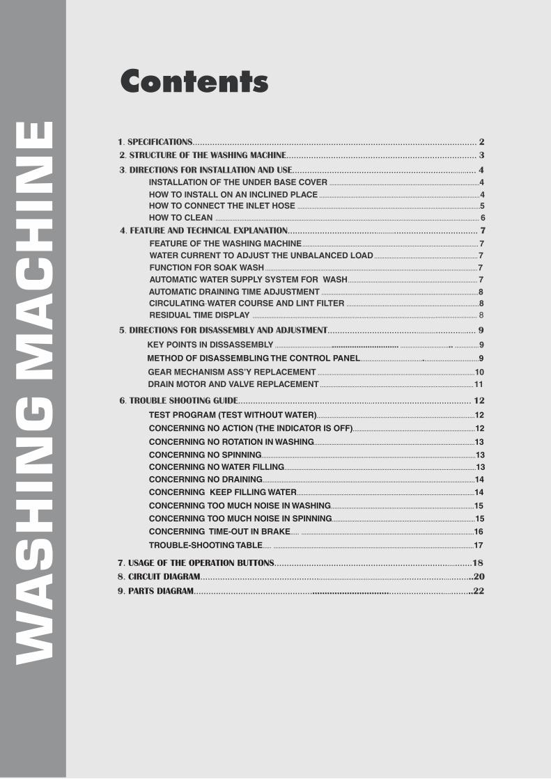
EContents
1. SPECIFICATIONS................................................................................................................... 2
2. STRUCTURE OF THE WASHING MACHINE............................................................................. 3
3. DIRECTIONS FOR INSTALLATION AND USE............................................................................ 4
INSTALLATION OF THE UNDER BASE COVER .......................................................................................4HOW TO INSTALL ON AN INCLINED PLACE .............................................................................................4HOW TO CONNECT THE INLET HOSE ..........................................................................................................5HOW TO CLEAN ......................................................................................................................................................... 6
4. FEATURE AND TECHNICAL EXPLANATION............................................................................... 7
FEATURE OF THE WASHING MACHINE ...................................................................................................... 7WATER CURRENT TO ADJUST THE UNBALANCED LOAD ............................................................7FUNCTION FOR SOAK WASH ...........................................................................................................................7AUTOMATIC WATER SUPPLY SYSTEM FOR WASH........................................................................... 7AUTOMATIC DRAINING TIME ADJUSTMENT ...........................................................................................8CIRCULATING-WATER COURSE AND LINT FILTER .............................................................................8RESIDUAL TIME DISPLAY .................................................................................................................................. 8
5. DIRECTIONS FOR DISASSEMBLY AND ADJUSTMENT............................................................... 9
GEAR MECHANISM ASS’Y REPLACEMENT ...........................................................................................10DRAIN MOTOR AND VALVE REPLACEMENT .........................................................................................11
6. TROUBLE SHOOTING GUIDE............................................................................................... 12
TEST PROGRAM (TEST WITHOUT WATER).......................................................................................12
7. .................................................................................18USAGE OF THE OPERATION BUTTONS
KEY POINTS IN DISSASSEMBLY ................................................................ ............................... ..............9
METHOD OF DISASSEMBLING THE CONTROL PANEL.................................................................9
CONCERNING NO ACTION (THE INDICATOR IS OFF).......................................................................12
CONCERNING NO ROTATION IN WASHING ................................................................. ............................13
CONCERNING NO SPINNING ........................ ....................................................................... .. ...........................13CONCERNING NO WATER FILLING .................................................................................... ...........................13
CONCERNING NO DRAINING ................................................................................................ ...........................14
CONCERNING KEEP FILLING WATER ............................................................................ ...........................14
CONCERNING TOO MUCH NOISE IN WASHING ........................................................ ...........................15
CONCERNING TOO MUCH NOISE IN SPINNING ......................................................... ..........................15
CONCERNING TIME-OUT IN BRAKE ............................................................................... ............ ..............16
TROUBLE-SHOOTING TABLE ............................................................................................... ............ ..............17
8. ................................................ ............................ 20CIRCUIT DIAGRAM ..................................................
9. ................................................ ................................. 22PARTS DIAGRAM ............................... ..
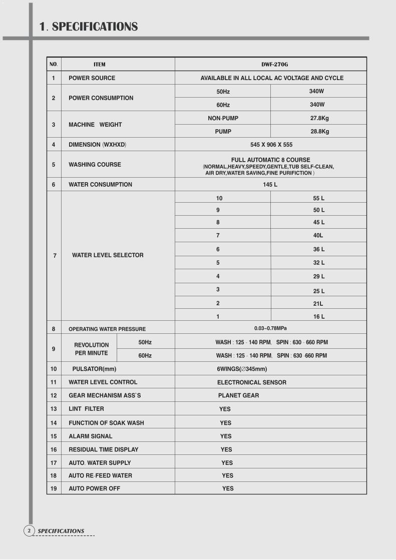
1. SPECIFICATIONS
2 SPECIFICATIONS
1 POWER SOURCE AVAILABLE IN ALL LOCAL AC VOLTAGE AND CYCLE
2 POWER CONSUMPTION
3 MACHINE WEIGHT
4 DIMENSION (WXHXD) 545 X 906 X 555
5 WASHING COURSEFULL AUTOMATIC 8 COURSE
(NORMAL,HEAVY,SPEEDY,GENTLE,TUB SELF-CLEAN, AIR DRY,WATER SAVING,FINE PURIFICTION )
6 WATER CONSUMPTION 145 L
7 WATER LEVEL SELECTOR
8 OPERATING WATER PRESSURE
50Hz WASH : 125 - 140 RPM, SPIN : 630 - 660 RPM9
60Hz WASH : 125 - 140 RPM, SPIN : 630 -660 RPM
10
11 WATER LEVEL CONTROL ELECTRONICAL SENSOR
12 GEAR MECHANISM ASS`S PLANET GEAR
13 LINT FILTER YES
14 FUNCTION OF SOAK WASH YES
15 ALARM SIGNAL YES
16 RESIDUAL TIME DISPLAY YES
17 AUTO. WATER SUPPLY YES
18 AUTO RE-FEED WATER YES
19 AUTO POWER OFF YES
NO.
50Hz
60Hz
NON-PUMP
PUMP
27.8Kg
28.8Kg
340W
10 55 L
REVOLUTIONPER MINUTE
ITEM
9 50 L
8 45 L
7 40L
6 36 L
5 32 L
4
3
2
1 16 L
29 L
25 L
21L
0.03~0.78MPa
PULSATOR(mm) 6WINGS(Æ345mm)
DWF-270G
340W
2. STRUCTURE OF THE WASHING MACHINE
3STRUCTURE
Accessories
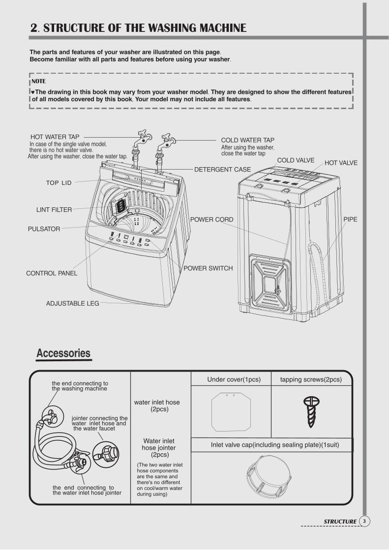
The parts and features of your washer are illustrated on this page.Become familiar with all parts and features before using your washer.
NOTE
©The drawing in this book may vary from your washer model. They are designed to show the different features of all models covered by this book, Your model may not include all features.
the end connecting to the water inlet hose jointer
the end connecting to the washing machine
jointer connecting the water inlet hose and the water faucet
water inlet hose (2pcs)
Water inlet hose jointer (2pcs)
(The two water inlet hose components are the same and there's no different on cool/warm water during using)
Under cover(1pcs) tapping screws(2pcs)
Inlet valve cap(including sealing plate)(1suit)
TOP LID
HOT WATER TAP
After using the washer, close the water tap.
In case of the single valve model,there is no hot water valve.
� COLD WATER TAP After using the washer,
close the water tap
LINT FILTER
CONTROL PANEL
ADJUSTABLE LEG
POWER SWITCH
PULSATOR
DETERGENT CASE
POWER CORD PIPE
COLD VALVE HOT VALVE
3. DIRECTIONS FOR INSTALLATION AND USE
4 DIRECTIONS
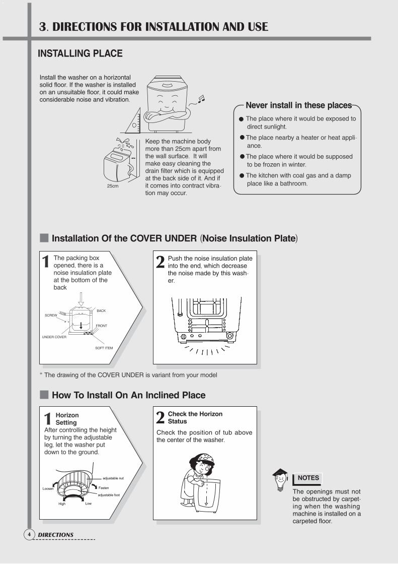
The openings must notbe obstructed by carpet-ing when the washingmachine is installed on acarpeted floor.
Installation Of the COVER UNDER (Noise Insulation Plate)
How To Install On An Inclined Place
The place where it would be exposed todirect sunlight.
The place nearby a heater or heat appli-ance.
The place where it would be supposedto be frozen in winter.
The kitchen with coal gas and a dampplace like a bathroom.
NOTES
10Cm
Install the washer on a horizontalsolid floor. If the washer is installedon an unsuitable floor, it could makeconsiderable noise and vibration.
INSTALLING PLACE
Never install in these places
2 Push the noise insulation plateinto the end, which decreasethe noise made by this wash-er.
1 The packing box opened, there is a noise insulation plate at the bottom of theback
2 Check the Horizon Status
Check the position of tub abovethe center of the washer.
1 Horizon Setting
After controlling the heightby turning the adjustableleg, let the washer putdown to the ground.
Keep the machine bodymore than 25cm apart fromthe wall surface. It willmake easy cleaning thedrain filter which is equippedat the back side of it. And ifit comes into contract vibra-tion may occur.
* The drawing of the COVER UNDER is variant from your model
25cm
SCREW
UNDER COVER
BACK
FRONT
SOFT ITEM
Loosen Fasten
High Low
adjustable nut
adjustable foot
5CONNECTION
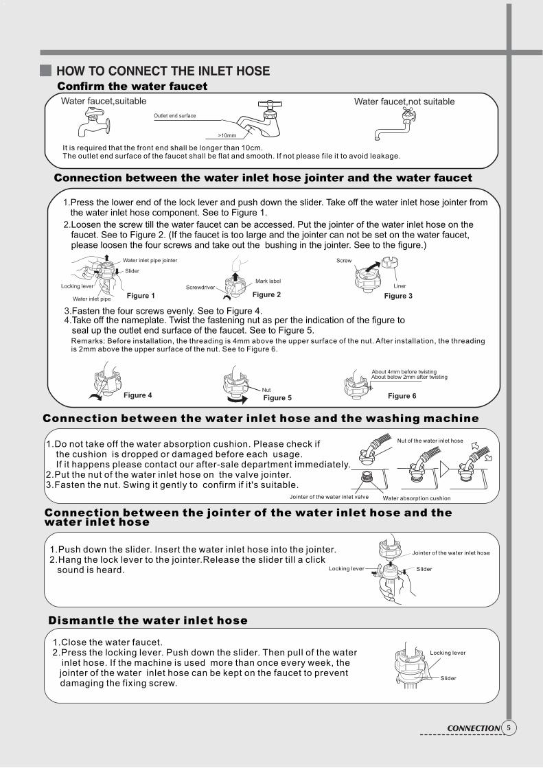
HOW TO CONNECT THE INLET HOSE
Water faucet,suitable Water faucet,not suitable
It is required that the front end shall be longer than 10cm.The outlet end surface of the faucet shall be flat and smooth. If not please file it to avoid leakage.
2.Loosen the screw till the water faucet can be accessed. Put the jointer of the water inlet hose on the faucet. See to Figure 2. (If the faucet is too large and the jointer can not be set on the water faucet, please loosen the four screws and take out the bushing in the jointer. See to the figure.)
1.Press the lower end of the lock lever and push down the slider. Take off the water inlet hose jointer from the water inlet hose component. See to Figure 1.
Remarks: Before installation, the threading is 4mm above the upper surface of the nut. After installation, the threading is 2mm above the upper surface of the nut. See to Figure 6.
4.Take off the nameplate. Twist the fastening nut as per the indication of the figure to seal up the outlet end surface of the faucet. See to Figure 5.
3.Fasten the four screws evenly. See to Figure 4.
>10mm
Outlet end surface
Nut
About 4mm before twistingAbout below 2mm after twisting
Figure 5
Figure 1
Figure 4 Figure 6
Slider
Water inlet pipe jointer
Water inlet pipe
Locking lever
Confirm the water faucet
Connection between the water inlet hose jointer and the water faucet
ScrewdriverMark label
Figure 2
Screw
Liner
Figure 3
Connection between the water inlet hose and the washing machine
1.Do not take off the water absorption cushion. Please check if the cushion is dropped or damaged before each usage. If it happens please contact our after-sale department immediately.2.Put the nut of the water inlet hose on the valve jointer.3.Fasten the nut. Swing it gently to confirm if it's suitable.
Water absorption cushion
Nut of the water inlet hose
Jointer of the water inlet valve
Connection between the jointer of the water inlet hose and the water inlet hose
SliderLocking lever
Jointer of the water inlet hose1.Push down the slider. Insert the water inlet hose into the jointer.2.Hang the lock lever to the jointer.Release the slider till a click sound is heard.
Locking lever
Slider
Dismantle the water inlet hose
1.Close the water faucet.2.Press the locking lever. Push down the slider. Then pull of the water inlet hose. If the machine is used more than once every week, the jointer of the water inlet hose can be kept on the faucet to prevent damaging the fixing screw.
6 CONVENIENCE
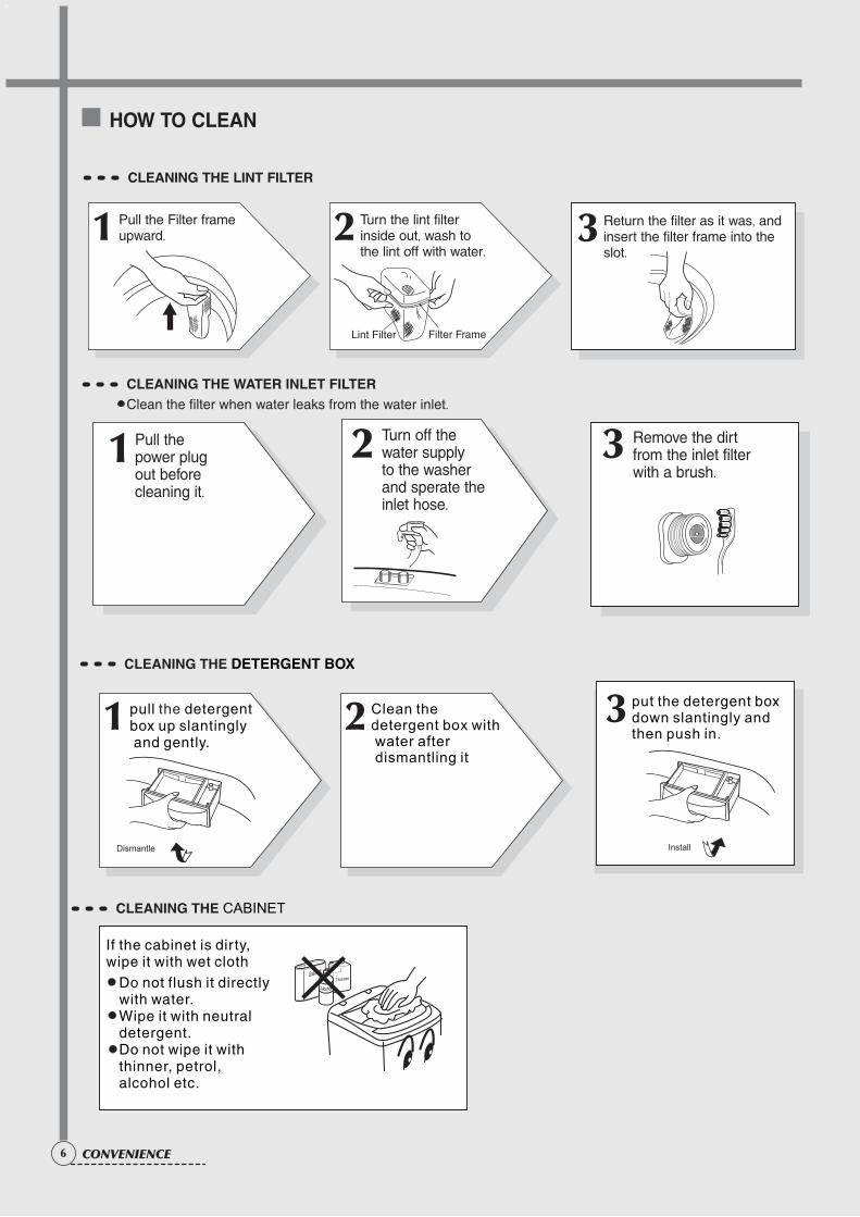
HOW TO CLEAN
Remove the dirtfrom the inlet filterwith a brush.
1 Pull the power plugout beforecleaning it.
2 Turn off thewater supply to the washerand sperate theinlet hose.
3
CLEANING THE LINT FILTER
CLEANING THE WATER INLET FILTERClean the filter when water leaks from the water inlet.
CLEANING THE DETERGENT BOX
1 pull detergent box up slantingly and gently.
the
2 Clean the
detergent box with water after dismantling it
3 put the detergent box down slantingly and then push in.
Dismantle Install
CLEANING THE CABINET
If the cabinet is dir ty, wipe it with wet cloth
Do not flush it directly with water.Wipe it with neutral detergent.Do not wipe it with thinner, petrol, alcohol etc.
3 Return the filter as it was, andinsert the filter frame into theslot.
1 Pull the Filter frameupward. 2 Turn the lint filter
inside out, wash tothe lint off with water.
Filter FrameLint Filter
4. FEATURE AND TECHNICAL EXPLANATION
7FEATURE
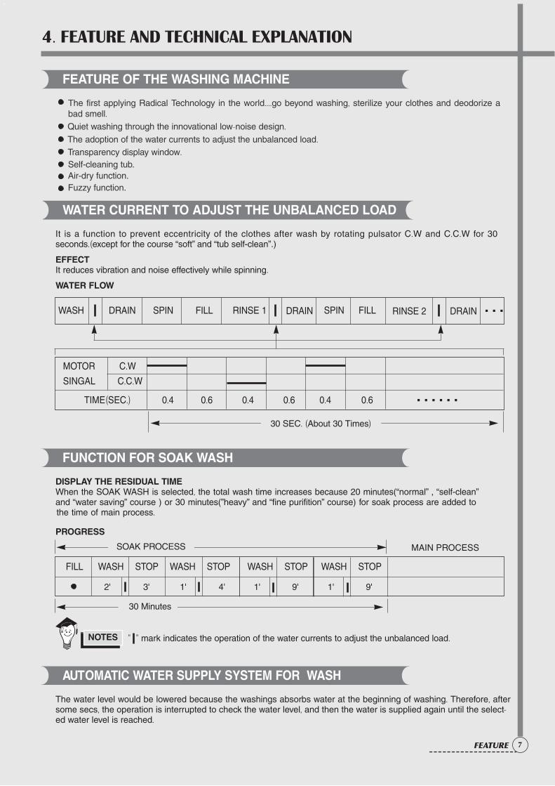
WASH DRAIN SPIN FILL RINSE 1 S PIN F ILL DRAIN RINSE 2 DRAIN
MOTOR C.WSINGAL C.C.W
TIME(SEC.) 0.4 0.6 0.4 0.6 0.4 0.6
30 SEC. (About 30 Times)
FEATURE OF THE WASHING MACHINE
The first applying Radical Technology in the world....go beyond washing, sterilize your clothes and deodorize abad smell.Quiet washing through the innovational low-noise design.The adoption of the water currents to adjust the unbalanced load.
WATER CURRENT TO ADJUST THE UNBALANCED LOAD
It is a function to prevent eccentricity of the clothes after wash by rotating pulsator C.W and C.C.W for 30seconds.(except for the course “soft” and “tub self-clean”.)
EFFECTIt reduces vibration and noise effectively while spinning.
WATER FLOW
FUNCTION FOR SOAK WASH
DISPLAY THE RESIDUAL TIMEWhen the SOAK WASH is selected, the total wash time increases because 20 minutes(“normal” , “self-clean”and “water saving” course ) or 30 minutes(”heavy” and “fine purifition” course) for soak process are added to
PROGRESS
AUTOMATIC WATER SUPPLY SYSTEM FOR WASH
The water level would be lowered because the washings absorbs water at the beginning of washing. Therefore, aftersome secs, the operation is interrupted to check the water level, and then the water is supplied again until the select-ed water level is reached.
" " mark indicates the operation of the water currents to adjust the unbalanced load.NOTES
Transparency display window.Self-cleaning tub.Air-dry function.
......
...
FILL WASH STOP WASH STOP WASH STOP WASH STOP
SOAK PROCESS MAIN PROCESS
30 Minutes
2' 3' 1' 4' 1' 9' 1' 9'
Fuzzy function.
the time of main process.
8 FEATURE
FUNCTIONAL PRINCIPLE
The micom can remember the time from the begining of drain to reset point when the pressure switch reachesto”OFF”point
DrainingGood draining The washer begins spin process after drainage.
conditionBad draining Draininig time is prolonged.
No draining Program is stopped and gives the alarm.
vement of the ProgramDrain Time Mo
Less thanContinue draining
4 minutes
More thanProgram stops and gives the alarm with blinked on display lamp.
4 minutes
AUTOMATIC DRAINNING TIME ADJUSTMENT
This system adjusts the draining time automatically according to the draining condition.
CIRCULATING-WATER COURSE AND LINT FILTER
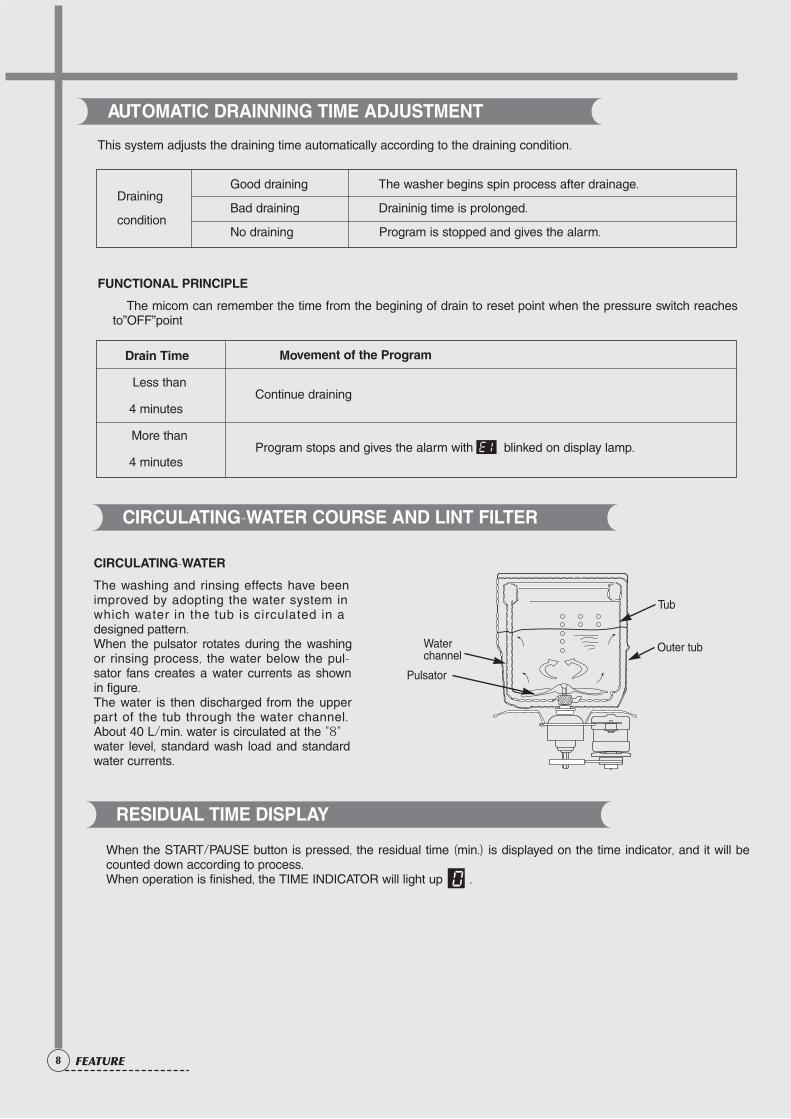
Tub
Outer tubWaterchannel
Pulsator
CIRCULATING-WATER
The washing and rinsing effects have beenimproved by adopting the water system inwhich water in the tub is circulated in adesigned pattern.When the pulsator rotates during the washingor rinsing process, the water below the pul-sator fans creates a water currents as shownin figure.The water is then discharged from the upperpart of the tub through the water channel.About 40 L/min. water is circulated at the "8"water level, standard wash load and standardwater currents.
When the START/PAUSE button is pressed, the residual time (min.) is displayed on the time indicator, and it will becounted down according to process.When operation is finished, the TIME INDICATOR will light up .
RESIDUAL TIME DISPLAY
5. DIRECTIONS FOR DISASSEMBLY AND ADJUSTMENT
9DIRECTIONS
BEFORE ATTEMPTING TO SERVICE OR ADJUST ANY PART OF THE WASHING MACHINE, DISCONNECTTHE POWER CORD FROM THE ELECTRIC OUTLET.
Warning
1) GENERAL ATTENTION
2)POINTS OF ATTENTION IN USAGE OF ELECTRIC COMPONENTS
Take care of the screws in order to use them in installation.
In case that the power is on, the earthing circuit of the computer sequencer can have a high voltage to earth. Take care not to get electric shock. Store the computer sequencer at shading and dry places. Avoid direct sunlight.
KEY POINTS IN DISASSEMBLY
Be sure to pull off the power plug in disassembly or maintenance.
Use stipulated crimp terminals in connecting the wires between the conducting wires as far as possible, and fix with suitable tools, and insulate with insulation tape completely.
In inserting the conducting wires, be sure to plug the pins to the root and make it hard to be pulled out. If welding is needed, be careful not to touch the plastic or other insulation parts with the iron. When connecting the wires, be sure not to make the wire touch the mobile parts like the belt, radiating pulley and jib etc., and the sharp protruding parts and the parts with high temperature (motor).Connect and fix the wires as per their original mode.
If there's metal object at the wire fixing point, be sure to insulate with insulation materials.
METHOD OF DISASSEMBLING THE CONTROL PANEL
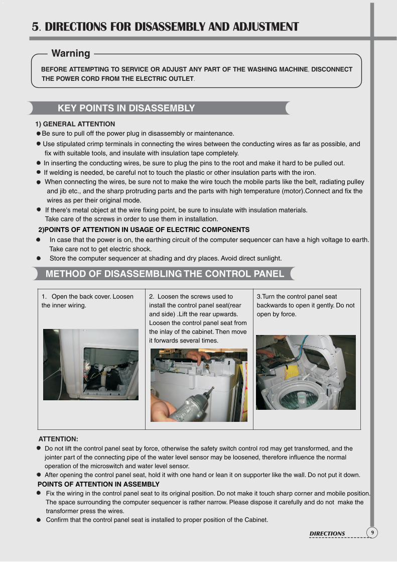
1. Open the back cover. Loosen the inner wiring.
2. Loosen the screws used to install the control panel seat(rear and side) .Lift the rear upwards. Loosen the control panel seat from the inlay of the cabinet. Then move it forwards several times.
3.Turn the control panel seat backwards to open it gently. Do not open by force.
ATTENTION: Do not lift the control panel seat by force, otherwise the safety switch control rod may get transformed, and the jointer part of the connecting pipe of the water level sensor may be loosened, therefore influence the normal operation of the microswitch and water level sensor. After opening the control panel seat, hold it with one hand or lean it on supporter like the wall. Do not put it down.
POINTS OF ATTENTION IN ASSEMBLY Fix the wiring in the control panel seat to its original position. Do not make it touch sharp corner and mobile position. The space surrounding the computer sequencer is rather narrow. Please dispose it carefully and do not make the transformer press the wires. Confirm that the control panel seat is installed to proper position of the Cabinet.
10 DIRECTIONS
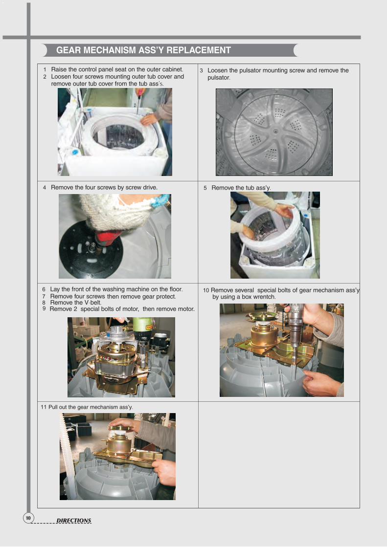
GEAR MECHANISM ASS’Y REPLACEMENT
1 Raise the control panel seat on the outer cabinet.2 Loosen four screws mounting outer tub cover and
remove outer tub cover from the tub ass's.
3 Loosen the pulsator mounting screw and remove thepulsator.
4 Remove the four screws by screw drive. 5 Remove the tub ass’y.
6 Lay the front of the washing machine on the floor.7 Remove four screws then remove gear protect.8 Remove the V-belt.9 Remove 2 special bolts of motor, then remove motor.
11 Pull out the gear mechanism ass’y.
10 Remove several special bolts of gear mechanism ass’y by using a box wrentch.
11DIRECTIONS
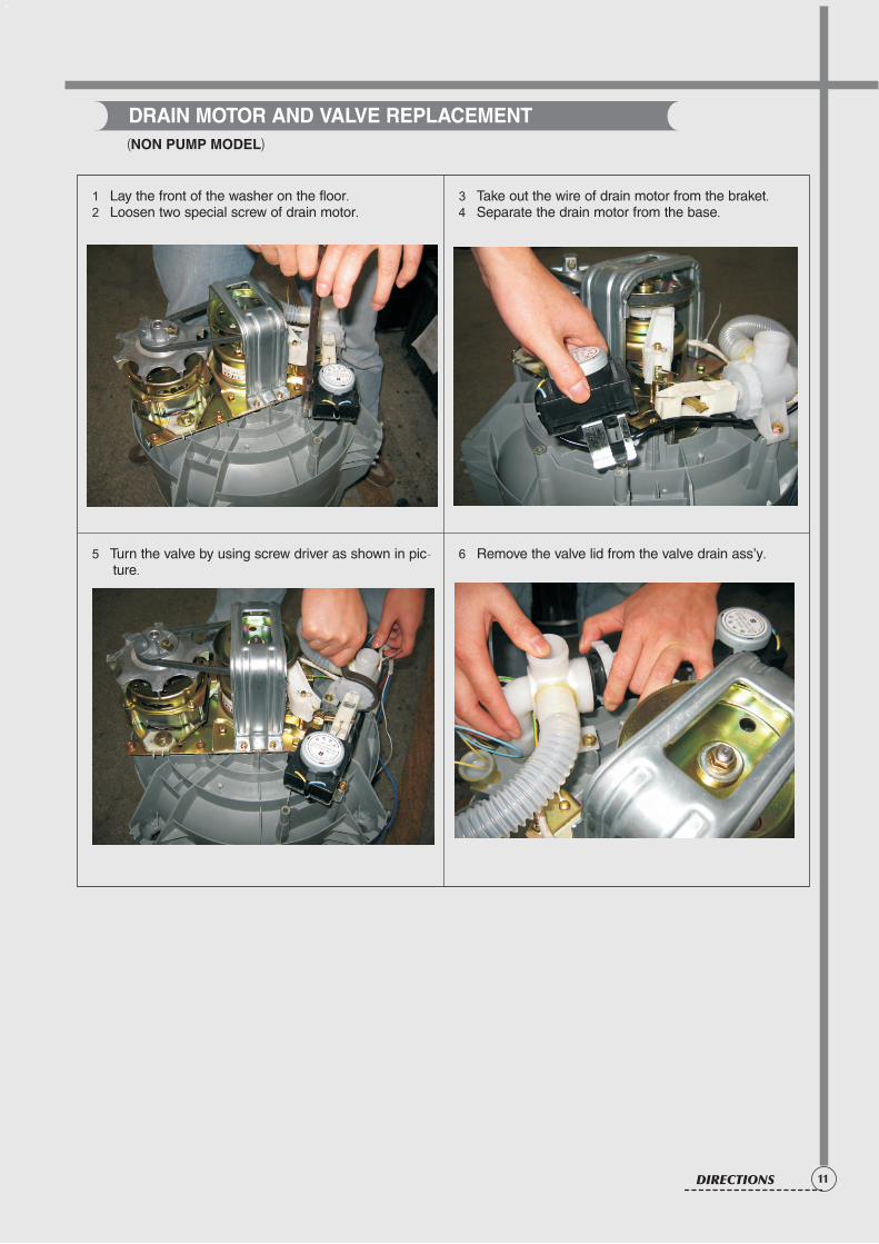
1 Lay the front of the washer on the floor.2 Loosen two special screw of drain motor.
5 Turn the valve by using screw driver as shown in pic-ture.
3 Take out the wire of drain motor from the braket.4 Separate the drain motor from the base.
6 Remove the valve lid from the valve drain ass’y.
(NON PUMP MODEL)
DRAIN MOTOR AND VALVE REPLACEMENT
12
6. TROUBLE SHOOTING GUIDE
CONCERNING NO ACTION (THE INDICATOR IS OFF)
Exist
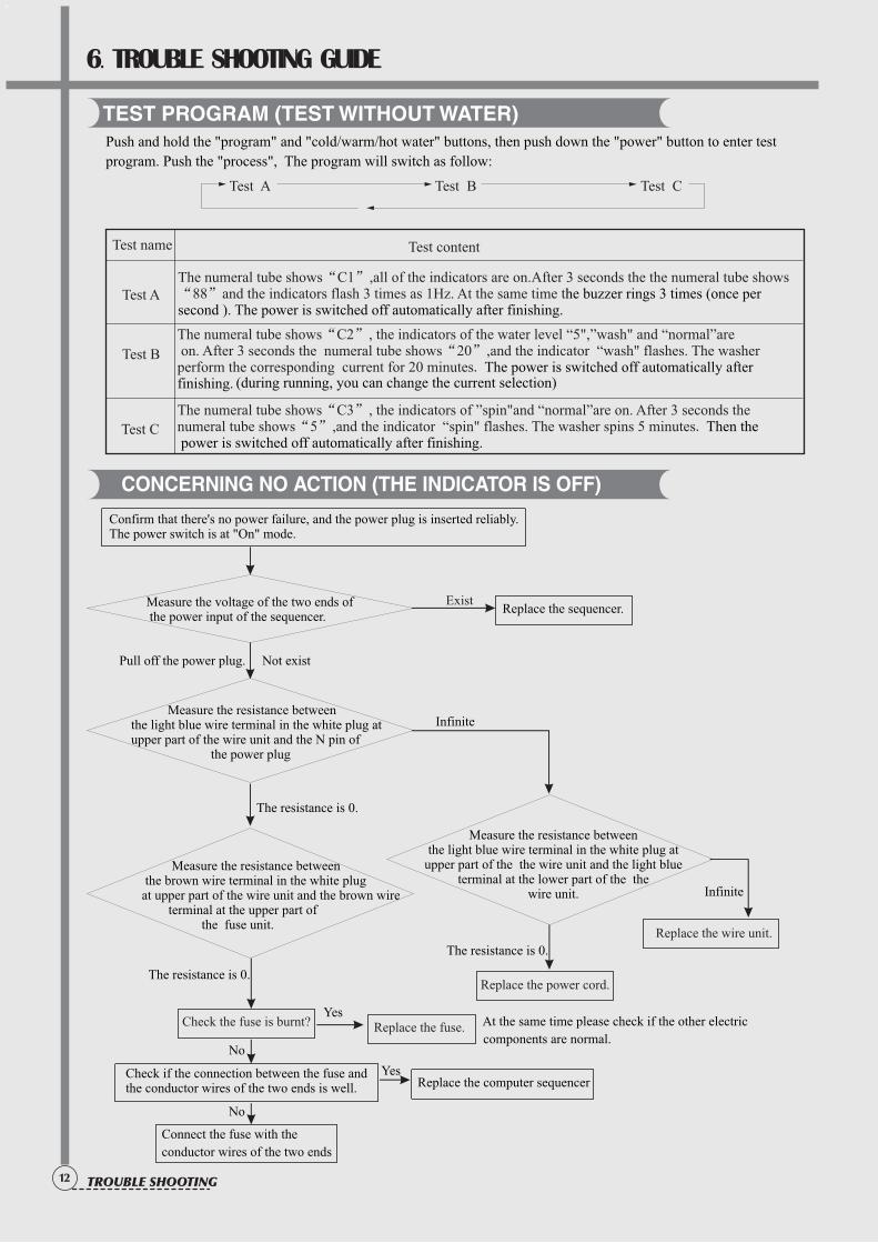
Measure the resistance between the light blue wire terminal in the white plug at
upper part of the the wire unit and the light blueterminal at the lower part of the the
wire unit.
Confirm that there's no power failure, and the power plug is inserted reliably. The power switch is at "On" mode.
Measure the voltage of the two ends of the power input of the sequencer.
Replace the sequencer.
Pull off the power plug. Not exist
Measure the resistance between the light blue wire terminal in the white plug at upper part of the wire unit and the N pin of the power plug
Infinite
Measure the resistance between the brown wire terminal in the white plug at upper part of the wire unit and the brown wire terminal at the upper part of the fuse unit.
The resistance is 0.
The resistance is 0.
The resistance is 0.
No
No
Yes
Yes
Infinite
Replace the wire unit.
Check the fuse is burnt? Replace the fuse.
Replace the computer sequencer
Replace the power cord.
At the same time please check if the other electric
components are normal.
Connect the fuse with the
conductor wires of the two ends
Check if the connection between the fuse andthe conductor wires of the two ends is well.
TEST PROGRAM (TEST WITHOUT WATER)
Push and hold the "program" and "cold/warm/hot water" buttons, then push down the "power" button to enter test
program. Push the "process", The program will switch as follow:
Test A Test B Test C
Test name
Test A
Test B
Test C
Test content
The numeral tube shows“C1”,all of the indicators are on.After 3 seconds the the numeral tube shows“88”and the indicators flash 3 times as 1Hz. At the same time the buzzer rings 3 times (once per second ). The power is switched off automatically after finishing.
(during running, you can change the current selection)
The numeral tube shows“C2”, the indicators of the water level “5",”wash" and “normal”are on. After 3 seconds the numeral tube shows“20”,and the indicator “wash" flashes. The washerperform the corresponding current for 20 minutes. The power is switched off automatically after finishing.
The numeral tube shows“C3”, the indicators of ”spin"and “normal”are on. After 3 seconds the numeral tube shows“5”,and the indicator “spin" flashes. The washer spins 5 minutes. Then the power is switched off automatically after finishing.
TROUBLE SHOOTING
13TROUBLE SHOOTING
Exist
Yes
Yes
Yes
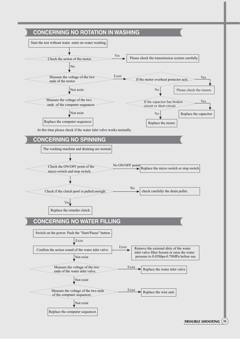
Start the test without water .enter no-water washing.
Measure the voltage of the two ends of the motor.
Measure the voltage of the two
ends of the computer sequencer.
If the motor overheat protector acts.
Replace the capacitor.
Replace the motor.
At this time please check if the water inlet valve works normally.
Check the action of the motor. Please check the transmission system carefully.
No
Not exist
Not exist
Replace the computer sequencer.
Please check the reason.
If the capacitor has broken circuit or short circuit
No
No
CONCERNING NO ROTATION IN WASHING
No ON/OFF point
No
The washing machine and draining are normal.
Replace the retarder clutch.
Check the ON/OFF point of the
micro switch and stop switch.
Check if the clutch pawl is pulled enough.
Replace the micro switch or stop switch.
check carefully the drain puller.
Yes
CONCERNING NO SPINNING
Exist
Exist
Exist
Exist
Switch on the power. Push the "Start/Pause" button.
Measure the voltage of the two ends of the water inlet valve.
Measure the voltage of the two ends of the computer sequencer.
Replace the water inlet valve.
Replace the wire unit.
Confirm the action sound of the water inlet valve. Remove the external dirty of the water inlet valve filter Screen or raise the water pressure to 0.03Mpa-0.78MPa before use.Not exist
Not exist
Not exist
Replace the computer sequencer.
CONCERNING NO WATER FILLING
14 TROUBLE SHOOTING
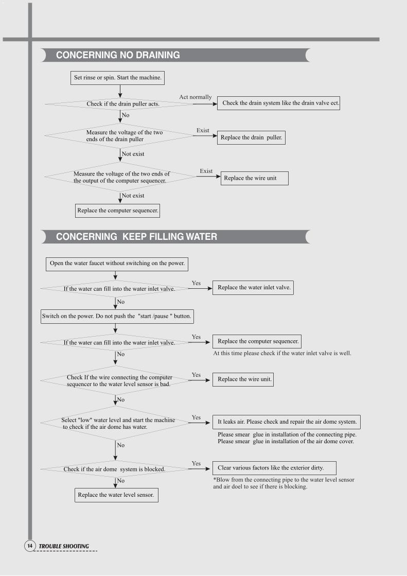
CONCERNING NO DRAINING
Act normally
Exist
Set rinse or spin. Start the machine.
Measure the voltage of the two ends of the drain puller
Measure the voltage of the two ends of the output of the computer sequencer.
Replace the drain puller.
Check if the drain puller acts. Check the drain system like the drain valve ect.
No
Not exist
Not exist
Replace the computer sequencer.
Yes
Yes
Yes
Yes
Yes
Open the water faucet without switching on the power.
If the water can fill into the water inlet valve.
If the water can fill into the water inlet valve.
Check if the air dome system is blocked.
Check If the wire connecting the computer sequencer to the water level sensor is bad.
Select "low" water level and start the machine to check if the air dome has water.
Switch on the power. Do not push the "start /pause " button.
Replace the water inlet valve.
Replace the computer sequencer.
Clear various factors like the exterior dirty.
Replace the water level sensor.
Replace the wire unit.
It leaks air. Please check and repair the air dome system.
Please smear glue in installation of the connecting pipe.Please smear glue in installation of the air dome cover.
No
No
No
No
No
At this time please check if the water inlet valve is well.
*Blow from the connecting pipe to the water level sensor and air doel to see if there is blocking.
CONCERNING KEEP FILLING WATER
Exist Replace the wire unit
No
No
Yes
Yes
Yes
Yes
Yes
No
Yes
Yes
No
No
No
No
No
No
Yes
Yes
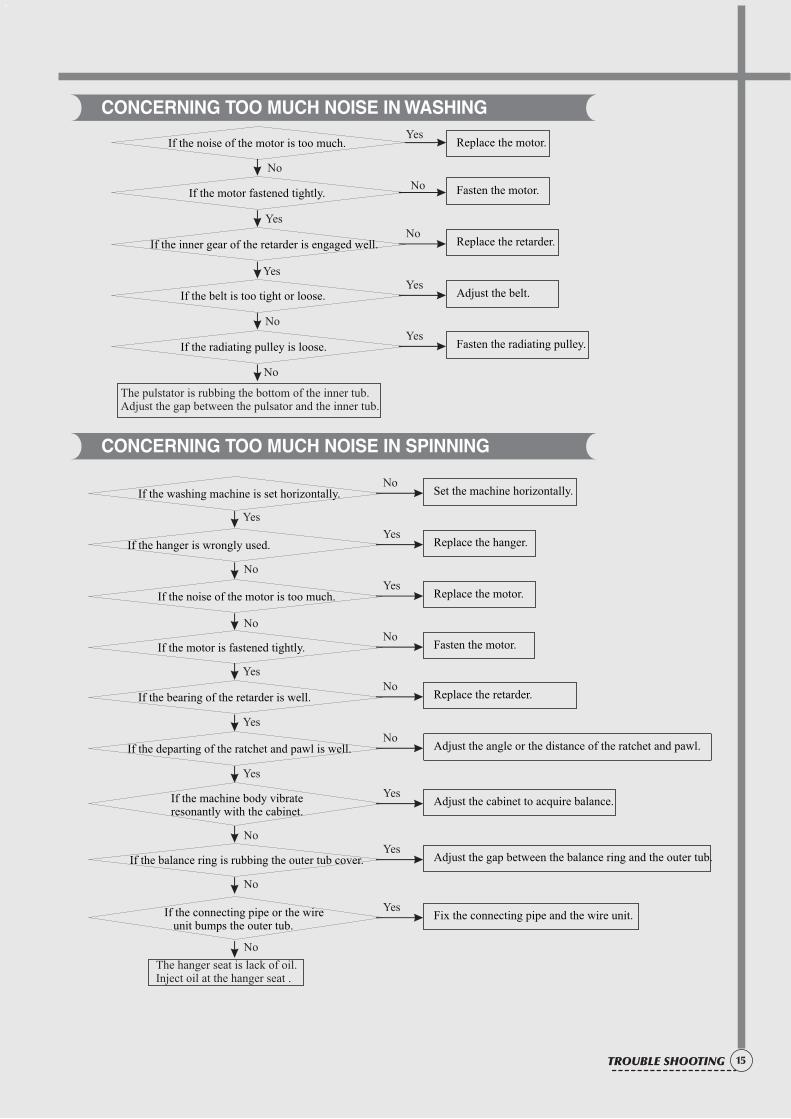
If the washing machine is set horizontally.
If the bearing of the retarder is well.
If the hanger is wrongly used.
If the departing of the ratchet and pawl is well.
If the noise of the motor is too much.
If the machine body vibrate resonantly with the cabinet.
If the motor is fastened tightly.
If the balance ring is rubbing the outer tub cover.
If the connecting pipe or the wire unit bumps the outer tub.
Set the machine horizontally.
Replace the retarder.
Replace the hanger.
Adjust the angle or the distance of the ratchet and pawl.
Replace the motor.
Adjust the cabinet to acquire balance.
Fasten the motor.
Adjust the gap between the balance ring and the outer tub.
Fix the connecting pipe and the wire unit.
The hanger seat is lack of oil. Inject oil at the hanger seat .
No
No
Yes
Yes
YesIf the noise of the motor is too much.
If the motor fastened tightly.
If the inner gear of the retarder is engaged well.
If the belt is too tight or loose.
If the radiating pulley is loose.
Fasten the motor.
Replace the retarder.
Adjust the belt.
Fasten the radiating pulley.
Replace the motor.
The pulstator is rubbing the bottom of the inner tub.Adjust the gap between the pulsator and the inner tub.
15TROUBLE SHOOTING
CONCERNING TOO MUCH NOISE IN WASHING
CONCERNING TOO MUCH NOISE IN SPINNING
No
Yes
Yes
No
No
16 TROUBLE SHOOTING
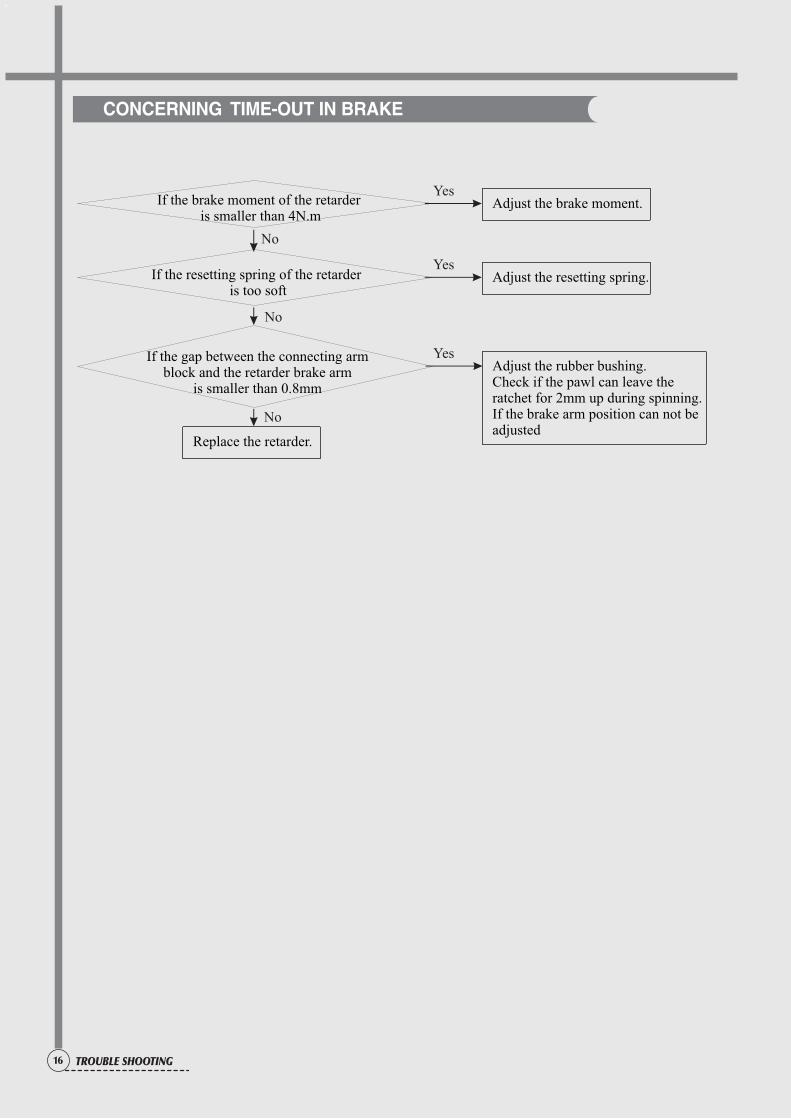
CONCERNING TIME-OUT IN BRAKE
Yes
Yes
Yes
No
Adjust the brake moment.
Adjust the resetting spring.
Adjust the rubber bushing. Check if the pawl can leave the ratchet for 2mm up during spinning. If the brake arm position can not be adjusted
Replace the retarder.
If the brake moment of the retarder is smaller than 4N.m
If the resetting spring of the retarder is too soft
If the gap between the connecting arm block and the retarder brake arm
is smaller than 0.8mm
No
No
17
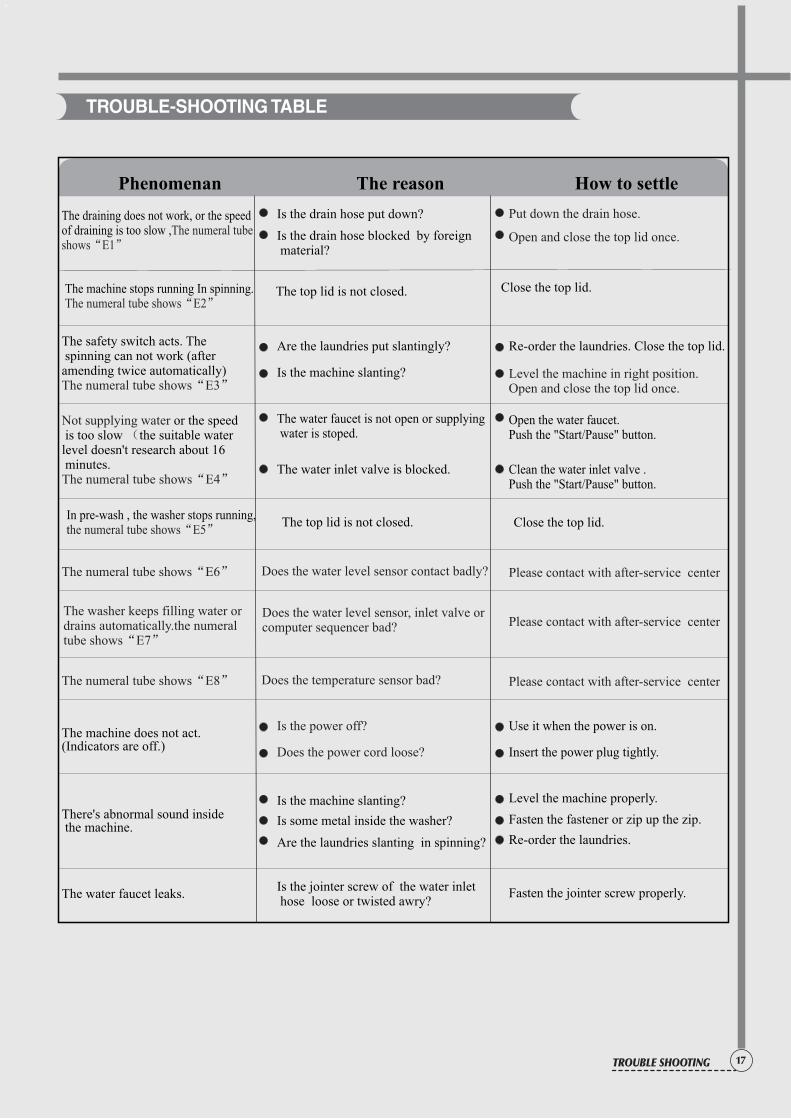
TROUBLE-SHOOTING TABLE
In pre-wash , the washer stops running,the numeral tube shows“E5”
The safety switch acts. The spinning can not work (after amending twice automatically)The numeral tube shows“E3”
Not supplying water (
The numeral tube shows“E4”
or the speed is too slow the suitable water level doesn't research about 16 minutes.
The draining does not work, or the speed of draining is too slow ,The numeral tube shows“E1”
The machine stops running In spinning.
The numeral tube shows“E2”
Is the power off?
Does the power cord loose?
Does the water level sensor contact badly? Please contact with after-service centerThe numeral tube shows“E6”
The top lid is not closed.
The top lid is not closed.
Close the top lid.
Close the top lid.
Is the drain hose put down?
Are the laundries put slantingly? Re-order the laundries. Close the top lid.
The water faucet is not open or supplying water is stoped.
The water inlet valve is blocked. Clean the water inlet valve .Push the "Start/Pause" button.
Open the water faucet. Push the "Start/Pause" button.
Is the drain hose blocked by foreign material?
Is the machine slanting?
Is some metal inside the washer?
Are the laundries slanting in spinning?
Is the jointer screw of the water inlet hose loose or twisted awry?
Insert the power plug tightly.
Use it when the power is on.
Level the machine properly.
Re-order the laundries.
Fasten the fastener or zip up the zip.
Fasten the jointer screw properly.The water faucet leaks.
The machine does not act.(Indicators are off.)
There's abnormal sound inside the machine.
Is the machine slanting? Level the machine in right position.Open and close the top lid once.
Phenomenan The reason How to settle
Put down the drain hose.
Open and close the top lid once.
The washer keeps filling water ordrains automatically.the numeral tube shows“E7”
Does the water level sensor, inlet valve orcomputer sequencer bad? Please contact with after-service center
Does the temperature sensor bad? Please contact with after-service centerThe numeral tube shows“E8”
TROUBLE SHOOTING
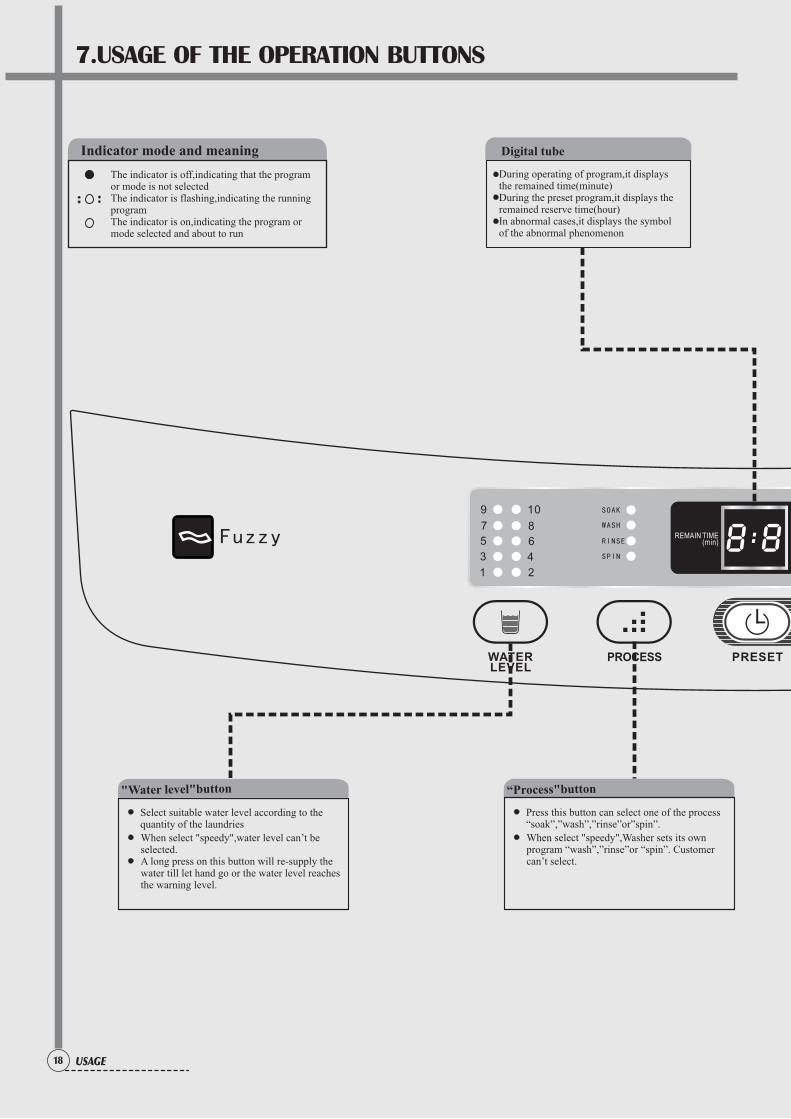
7.USAGE OF THE OPERATION BUTTONS
18 USAGE
Select suitable water level according to the quantity of the laundries
"Water level"button
When select selected.
"speedy",water level can’t be
A long press on this button will re-supply the water till let hand go or the water level reachesthe warning level.
Press this button can select one of the process“soak”,”wash”,”rinse”or”spin”.
“Process"button
When select program “wash”,”rinse”or “spin”. Customercan’t select.
"speedy",Washer sets its own
Indicator mode and meaning
The indicator is off,indicating that the program or mode is not selectedThe indicator is flashing,indicating the running programThe indicator is on,indicating the program or mode selected and about to run
During operating of program,it displays the remained time(minute)During the preset program,it displays the remained reserve time(hour)In abnormal cases,it displays the symbol of the abnormal phenomenon
Digital tube
COLD/WARM
HOT WATER
SOAK
WASH
RINSE
SPIN SPEEDY
GENTLE
NORMAL
HEAVY
COLD
WARM
HOT
TUB SELF-CLEAN
AIR DRY
WATER SAVING
FINE PURIFICTION
60-6069
19USAGE
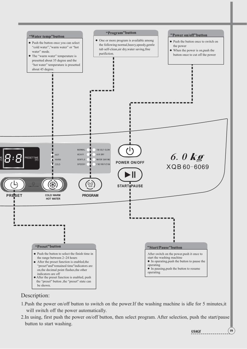
Push the button once to switch on
the power
When the power is on,push the
button once to cut off the power
"Power on/off"button
Push the button once you can select
“cold water”,”warm water” or “hot
water” mode.
The “warm water” temperature is
presetted about 35 degree and the
“hot water” temperature is presetted
about 45 degree.
“Water temp"buttonOne or more program is available among
the following:normal,heavy,speedy,gentle
tub self-clean,air dry,water saving,fine
purifiction.
“Program"button
“Preset"button
Push the button to select the finish time in the range between 2~24 hoursAfter the preset function is enabled,the “preset"and"remained time"indicators are on,the decimal point flashes,the other indicators are offAfter the preset function is enabled, push the “preset" button ,the “preset" state can be shown.
After switch on the power,push it once to start the washing machine In operating,push the button to pause the operating In pausing,push the button to resume operating
"Start/Pause"button
Description:
1.Push the power on/off button to switch on the power.If the washing machine is idle for 5 minutes,it
will switch off the power automatically.
2.In using, first push the power on/off button, then select program. After selection, push the start/pause
button to start washing.
COLD/WARM
HOT WATER
SOAK
WASH
RINSE
SPIN SPEEDY
GENTLE
NORMAL
HEAVY
COLD
WARM
HOT
TUB SELF-CLEAN
AIR DRY
WATER SAVING
FINE PURIFICTION
60-6069
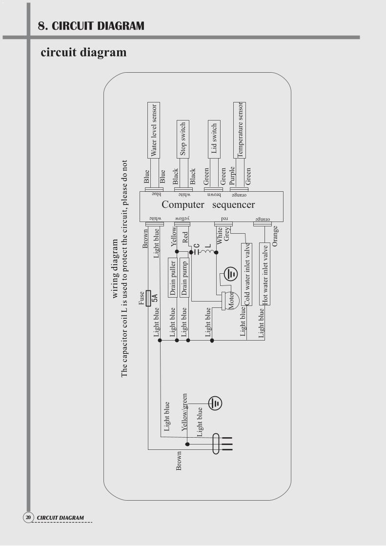
8. CIRCUIT DIAGRAM
20 CIRCUIT DIAGRAM
circuit diagram
5A
C L
wir
ing
dia
gra
mT
he
cap
acit
or
coil
L i
s u
sed
to p
rote
ct t
he
circ
uit
, p
leas
e d
o n
ot
Bro
wn
Yel
low
/gre
en
Lig
ht b
lue
Lig
ht b
lue
Lig
ht b
lue
Lig
ht b
lue
Lig
ht b
lue
Lig
ht b
lue
Lig
ht b
lueM
otor
Fus
eB
row
n
Dra
in p
ulle
r
Col
d w
ater
inl
et v
alve
Gre
y
Blu
e
Bla
ckY
ello
w
Gre
enL
id s
wit
ch
Sto
p sw
itch
Wat
er l
evel
sen
sor
Computer sequencer
Blu
e
Bla
ck
Pur
ple
Gre
enT
empe
ratu
re s
enso
r
Dra
in p
ump
Lig
ht b
lue
Red
Whi
te
Hot
wat
er i
nlet
val
veL
ight
blu
e
Ora
nge
orangebrownwhiteblue
orangeredyellowwhite
Gre
en
21CIRCUIT DIAGRAM
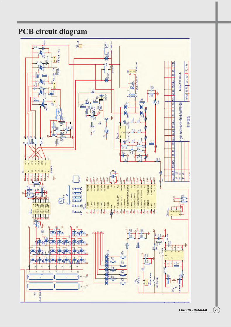
PCB circuit diagram
22 PARTS DIAGRAM
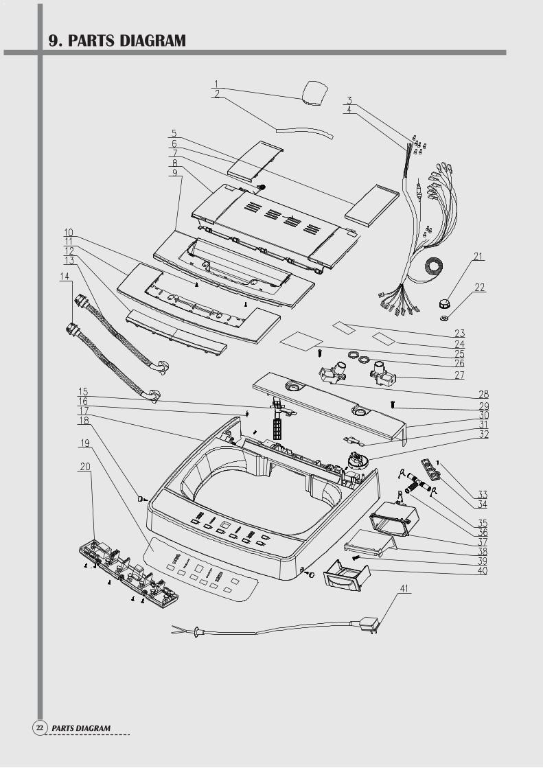
9. PARTS DIAGRAM
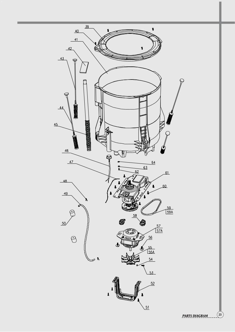
23PARTS DIAGRAM
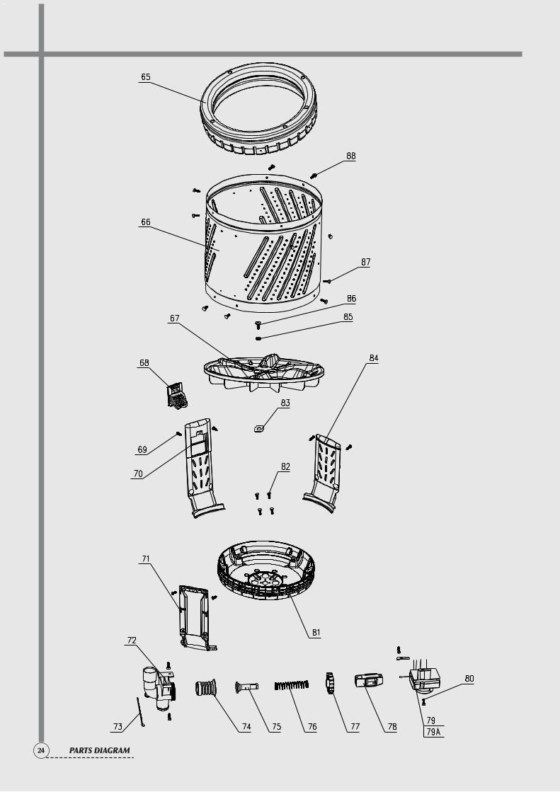
24 PARTS DIAGRAM
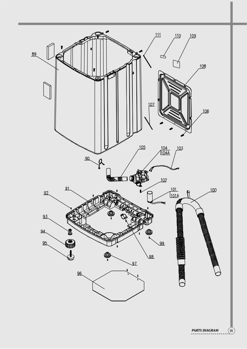
25PARTS DIAGRAM
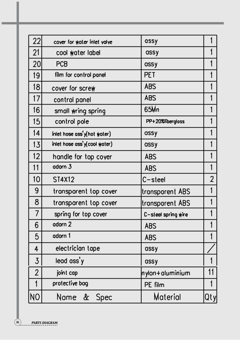
26 PARTS DIAGRAM
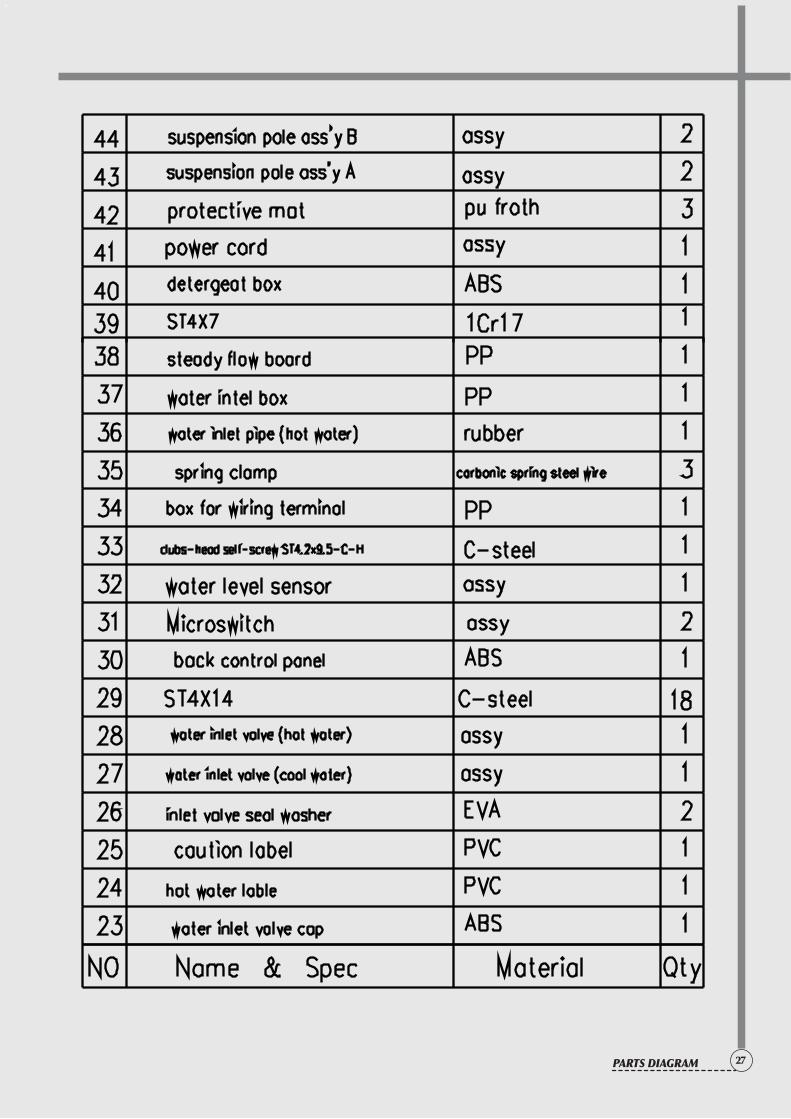
27PARTS DIAGRAM
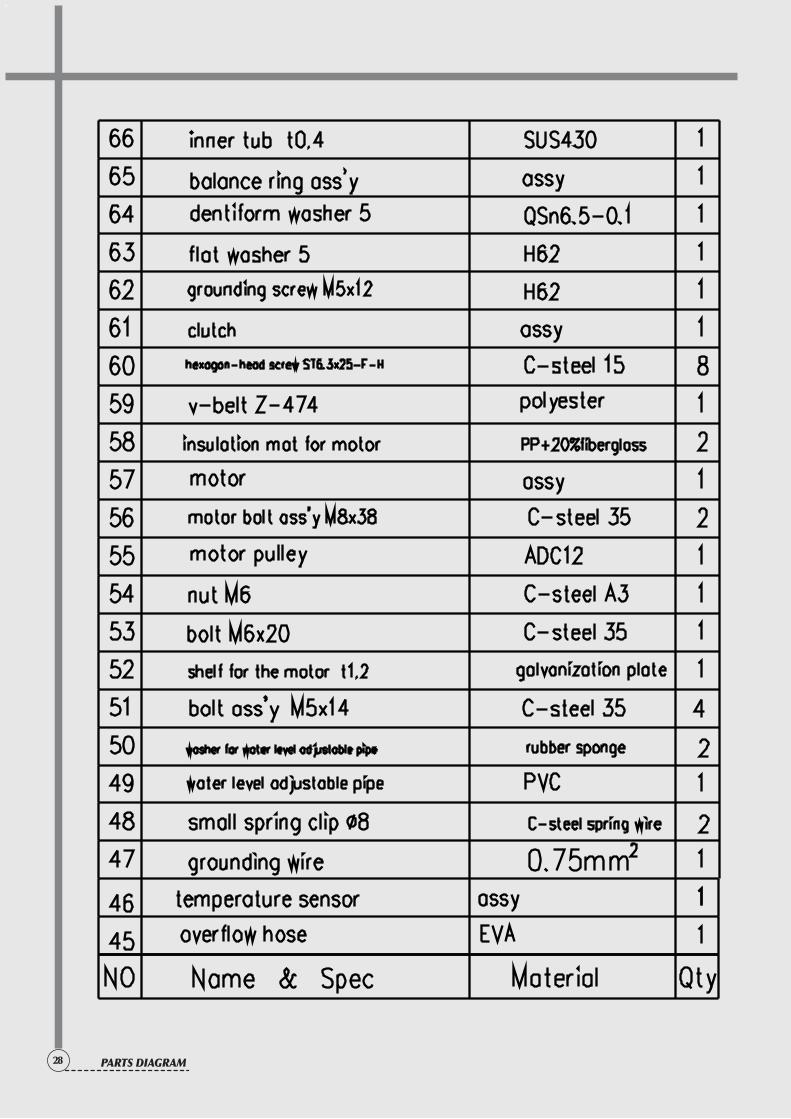
28 PARTS DIAGRAM
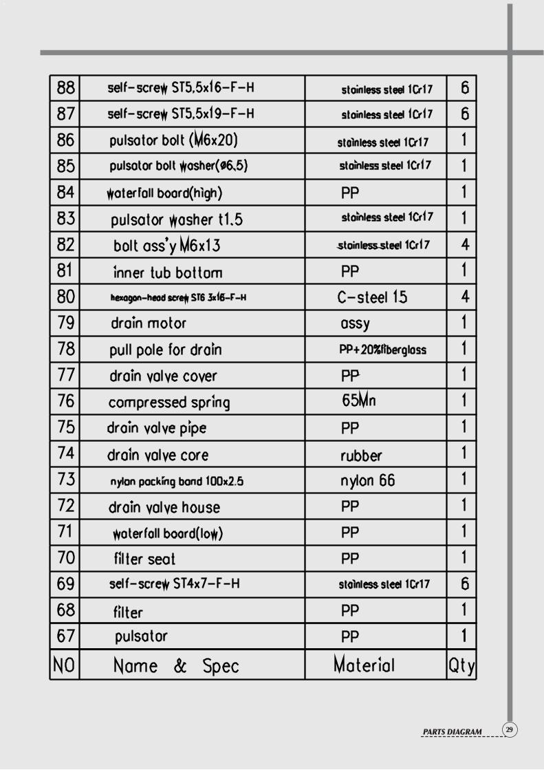
29PARTS DIAGRAM
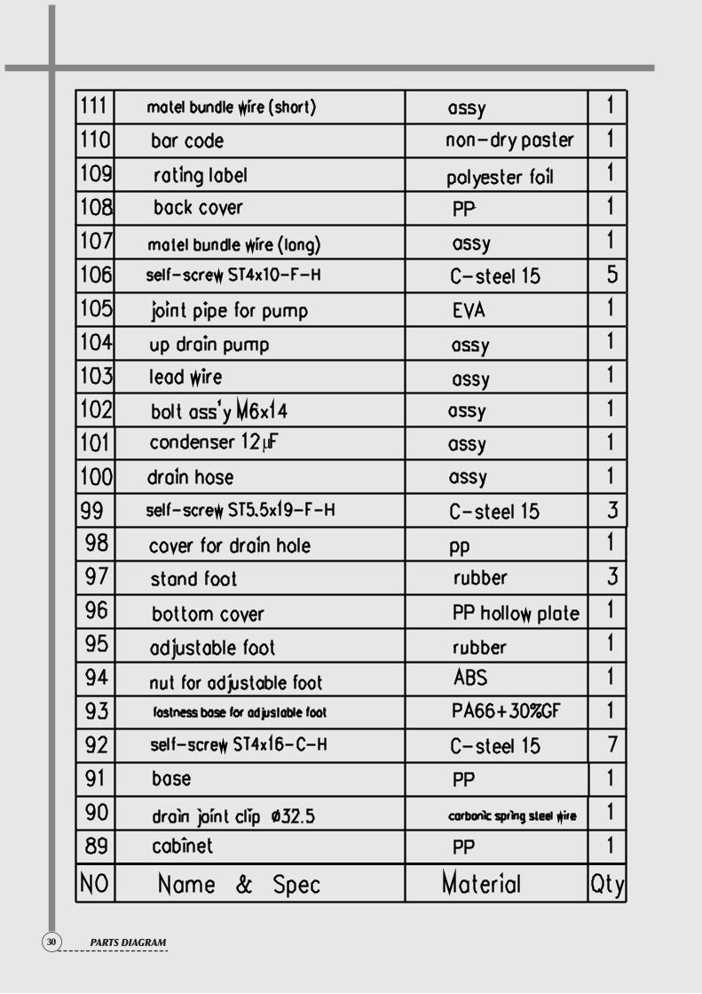
30 PARTS DIAGRAM