DVW32CB Quick Installation Guide = WIFI8E54C7-5G WPA2-PSK Wireless Key Randomly generated character...
3
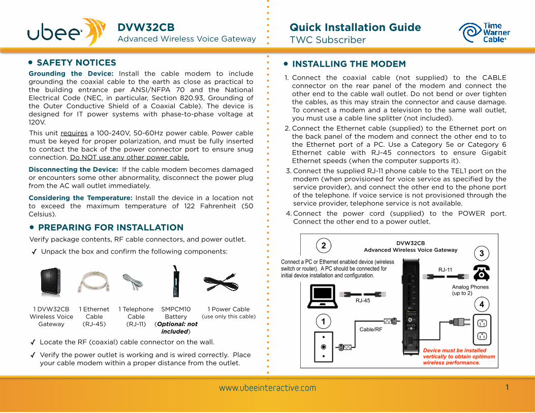
www.ubeeinteractive.com DVW32CB Advanced Wireless Voice Gateway Quick Installation Guide TWC Subscriber Grounding the Device: Install the cable modem to include grounding the coaxial cable to the earth as close as practical to the building entrance per ANSI/NFPA 70 and the National Electrical Code (NEC, in particular, Section 820.93, Grounding of the Outer Conductive Shield of a Coaxial Cable). The device is designed for IT power systems with phase-to-phase voltage at 120V. This unit requires a 100-240V, 50-60Hz power cable. Power cable must be keyed for proper polarization, and must be fully inserted to contact the back of the power connector port to ensure snug connection. Do NOT use any other power cable. Disconnecting the Device: If the cable modem becomes damaged or encounters some other abnormality, disconnect the power plug from the AC wall outlet immediately. Considering the Temperature: Install the device in a location not to exceed the maximum temperature of 122 Fahrenheit (50 Celsius). • SAFETY NOTICES • PREPARING FOR INSTALLATION Verify package contents, RF cable connectors, and power outlet. ✓ Unpack the box and confirm the following components: ✓ Locate the RF (coaxial) cable connector on the wall. ✓ Verify the power outlet is working and is wired correctly. Place your cable modem within a proper distance from the outlet. 1 DVW32CB Wireless Voice Gateway 1 Ethernet Cable (RJ-45) 1 Power Cable (use only this cable) • INSTALLING THE MODEM 1. Connect the coaxial cable (not supplied) to the CABLE connector on the rear panel of the modem and connect the other end to the cable wall outlet. Do not bend or over tighten the cables, as this may strain the connector and cause damage. To connect a modem and a television to the same wall outlet, you must use a cable line splitter (not included). 2. Connect the Ethernet cable (supplied) to the Ethernet port on the back panel of the modem and connect the other end to to the Ethernet port of a PC. Use a Category 5e or Category 6 Ethernet cable with RJ-45 connectors to ensure Gigabit Ethernet speeds (when the computer supports it). 3. Connect the supplied RJ-11 phone cable to the TEL1 port on the modem (when provisioned for voice service as specified by the service provider), and connect the other end to the phone port of the telephone. If voice service is not provisioned through the service provider, telephone service is not available. 4.Connect the power cord (supplied) to the POWER port. Connect the other end to a power outlet. 1 DVW32CB Advanced Wireless Voice Gateway RJ-45 Analog Phones (up to 2) 1 Telephone Cable (RJ-11) SMPCM10 Battery (Optional: not included) RJ-11 Connect a PC or Ethernet enabled device (wireless switch or router). A PC should be connected for initial device installation and configuration. Cable/RF Device must be installed vertically to obtain optimum wireless performance.
Transcript of DVW32CB Quick Installation Guide = WIFI8E54C7-5G WPA2-PSK Wireless Key Randomly generated character...
www.ubeeinteractive.com
DVW32CB Advanced Wireless Voice Gateway
Quick Installation Guide TWC Subscriber
Grounding the Device: Install the cable modem to include grounding the coaxial cable to the earth as close as practical to the building entrance per ANSI/NFPA 70 and the National Electrical Code (NEC, in particular, Section 820.93, Grounding of the Outer Conductive Shield of a Coaxial Cable). The device is designed for IT power systems with phase-to-phase voltage at 120V. This unit requires a 100-240V, 50-60Hz power cable. Power cable must be keyed for proper polarization, and must be fully inserted to contact the back of the power connector port to ensure snug connection. Do NOT use any other power cable.
Disconnecting the Device: If the cable modem becomes damaged or encounters some other abnormality, disconnect the power plug from the AC wall outlet immediately.
Considering the Temperature: Install the device in a location not to exceed the maximum temperature of 122 Fahrenheit (50 Celsius).
• SAFETY NOTICES
• PREPARING FOR INSTALLATIONVerify package contents, RF cable connectors, and power outlet.
✓ Unpack the box and confirm the following components:
✓ Locate the RF (coaxial) cable connector on the wall.
✓ Verify the power outlet is working and is wired correctly. Place your cable modem within a proper distance from the outlet.
1 DVW32CB Wireless Voice
Gateway
1 Ethernet Cable
(RJ-45)
1 Power Cable (use only this cable)
• INSTALLING THE MODEM1. Connect the coaxial cable (not supplied) to the CABLE
connector on the rear panel of the modem and connect the other end to the cable wall outlet. Do not bend or over tighten the cables, as this may strain the connector and cause damage. To connect a modem and a television to the same wall outlet, you must use a cable line splitter (not included).
2. Connect the Ethernet cable (supplied) to the Ethernet port on the back panel of the modem and connect the other end to to the Ethernet port of a PC. Use a Category 5e or Category 6 Ethernet cable with RJ-45 connectors to ensure Gigabit Ethernet speeds (when the computer supports it).
3. Connect the supplied RJ-11 phone cable to the TEL1 port on the modem (when provisioned for voice service as specified by the service provider), and connect the other end to the phone port of the telephone. If voice service is not provisioned through the service provider, telephone service is not available.
4. Connect the power cord (supplied) to the POWER port. Connect the other end to a power outlet.
1
DVW32CB Advanced Wireless Voice Gateway
RJ-45
Analog Phones (up to 2)
1 Telephone Cable (RJ-11)
SMPCM10 Battery
(Optional: not included)
RJ-11Connect a PC or Ethernet enabled device (wireless switch or router). A PC should be connected for initial device installation and configuration.
Cable/RF
Device must be installed vertically to obtain optimum wireless performance.
• UNDERSTANDING DEVICE CONNECTIONS AND BUTTONS
The rear and top panel of the DVW32CB contains the following connections and buttons:
TEL1-TEL2: Use to connect analog telephones to the device.
ETH1-ETH4: Use to connect to an Ethernet-enabled devices such as computers, gaming consoles or a wireless access point (LAN switch, router) using an RJ45 Ethernet cable. Each Ethernet port on the back panel of the device has two LEDs to indicate its status. When an Ethernet device is connected to the cable modem:
• The Orange LED is lit when connected at 10/100 Mbps speeds.
• The Green LED is lit when connected at 1000 speeds (Gigabit Ethernet).
• LED blinks (either Orange or Green) when data is passed between the cable modem and the connected device.
RESET: Use to reset the device. Take a small object like the end of a paper clip and insert it into the RESET opening. To power cycle the device, hold for less than 5 seconds. To reset to factory default settings, hold for more than 20 seconds. The DVW32CB will reset and reboot. WARNING: Resetting factory defaults will erase ANY and ALL settings that you have made and will restore the device to factory default settings.
CABLE: Use to connect to the coaxial cable from your Internet service provider.
POWER: Use to connect to the power adapter. Plug the other end into the wall power outlet.
WPS: Located on the top of the device, the use to set up the Wi-Fi Protected Setup (WPS) method to connect a PIN-protected Wi-Fi device to the cable modem. When a user pushes the WPS button or triggers WPS via Web UI, flashes for 4 minutes until PIN is entered from the wireless client. After a WiFi client attaches successfully, the LED remains on for 5 minutes, then turns off.
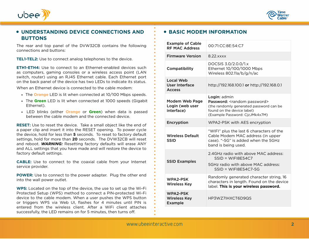
• BASIC MODEM INFORMATION
www.ubeeinteractive.com 2
Example of Cable RF MAC Address 00:71:CC:8E:54:C7
Firmware Version 8.22.xxxx
CompatibilityDOCSIS 3.0/2.0.0/1.x Ethernet 10/100/1000 Mbps Wireless 802.11a/b/g/n/ac
Local Web User Interface Access
http://192.168.100.1 or http://192.168.0.1
Modem Web Page Login (web user interface)
Login: admin Password: <random password> (the randomly generated password can be found on the device label) (Example Password: CjzJMk4x7M)
Encryption WPA2-PSK with AES encryption
Wireless Default SSID
“WIFI” plus the last 6 characters of the Cable Modem MAC address (in upper case). “-5G” is added when the 5GHz band is being used.
SSID Examples
2.4GHz radio with above MAC address: SSID = WIFI8E54C7
5GHz radio with above MAC address: SSID = WIFI8E54C7-5G
WPA2-PSK Wireless Key
Randomly generated character string, 16 characters in length. Found on the device label. This is your wireless password.
WPA2-PSK Wireless Key Example
HP3WZ7IHXCT6D9QS

www.ubeeinteractive.com 3
• LED BEHAVIORLED LABEL POWER DS/US ONLINE 2.4G 5G TEL1 TEL2 MoCA BATTERY WPS ETHERNET 1-4
COLOR Blue Blue Blue Blue Blue Blue Blue Blue Blue White Green / Orange
Cable Modem Initialization
(1) Power On On
Flashes when US and DS scan is
in progress
. Flashes when
obtaining IP address and configuration
On if 2.4G WiFi
is enabled
Off if 2.4G
WIFI is disabled
On if 5G WiFi is
enabled
Off if 5G WIFI is
disabled
On if enabled
Off if not provisioned
Flashes if a call is in
progress or the EMTA
is attempting to register
On if enabled
Off if not provisioned
Flashes if a call is in
progress or the EMTA
is attempting to register
On if the device is
connected to a MoCA
network
Off if the device is
not connected to a MoCA
network
On if battery is installed and
AC power is on
Off if no AC power
Flashes when the power level
is low (30 minutes
remaining)
Off
On
(2) Load Image Off
On if Ethernet device is connected
(3) H/W Check
On (flashes just after
power on)
(4) DS Locked and Sync OK
(5) US Ranging
(6) US Ranging OK
(7) Registration OK
On(8) NACO Enable
(9) NACO Disable
Cable Modem Operation
(1) Attached CPE
On On
On if network connected
Off if network connect failed
When user pushes the WPS button or triggers
WPS via Web UI, flashes for 4 minutes until PIN is entered from the wireless client. After a WiFi client
attaches successfully, the LED remains on for 5
minutes, then turns off.
On Green = connected at 1000Mbps (GigE)
On Orange = connected at 10/100 Mbps
(2) CPE Data Tx/Rx
Flashes (Green or Orange) if connected
Firmware Upgrade On Flash On
On, blinks if WiFi
traffic, Off if 2.4G is disabled
On, blinks if WiFi
traffic, Off if 5G is
disabled
On, blinks if call
active. Off if disabled
On, blinks if call
active. Off if disabled
Off if not connected to MoCA network
On: battery inserted. Blinks: on
battery power. Off: no battery
✴ Please note that both the 2.4GHz and 5GHz radios are enabled by default.