DVPDNET-SL - deltaww.com€¦ · DeviceNet Network Scanner DVPDNET-SL 1.3 Specifications PLC that...
44
DVPDNET-SL DeviceNet Network Scanner Operation Manual DVP-0204520-03 2012-3-27
Transcript of DVPDNET-SL - deltaww.com€¦ · DeviceNet Network Scanner DVPDNET-SL 1.3 Specifications PLC that...
DVPDNET-SL DeviceNet Network Scanner Operation Manual
DVP-0204520-03
2012-3-27
DeviceNet Network Scanner DVPDNET-SL
Warning Please read this instruction carefully before use and follow this instruction to operate the device in order to
prevent damages on the device or injuries to staff.
Switch off the power before wiring.
DVPDNET-SL is an OPEN TYPE device. Therefore it should be installed in an enclosure free of airborne
dust, humidity, electric shock and vibration. The enclosure should prevent non-maintenance staff from
operating the device (e.g. key or specific tools are required for operating the enclosure) in case danger
and damage on the device may occur.
DVPDNET-SL is to be used for controlling the operating machine and equipment. In order not to damage
it, only qualified professional staff familiar with the structure and operation of DVPDNET-SL can install,
operate, wire and maintain it.
DO NOT connect AC power supply to any of the I/O terminals; otherwise serious damage may occur.
Check all the wirings again before switching on the power and DO NOT touch any terminal when the
power is switched on. Make sure the ground terminal is correctly grounded in order to prevent
electromagnetic interference.
Table of Contents 1 INTRODUCTION ....................................................................................................................................1
1.1 Features .............................................................................................................................................1
1.2 Basic Functions of DVPDNET-SL ......................................................................................................1
1.3 Specifications .....................................................................................................................................2
2 PRODUCT PROFILE & OUTLINE .........................................................................................................3
2.1 Dimension ..........................................................................................................................................3
2.2 Product Profiles ..................................................................................................................................3
2.3 DeviceNet Connection Port ................................................................................................................3
2.4 Address Switch...................................................................................................................................4
2.5 Function Switch ..................................................................................................................................4
2.6 Digital Indicator...................................................................................................................................5
2.7 Extension Port ....................................................................................................................................5
3 INSTALLATION ......................................................................................................................................6
3.1 Connecting DVPDNET-SL to DVP-SV MPU ......................................................................................6
3.2 Installing DVPDNET-SL and DVP-SV MPU on DIN Rail ....................................................................6
3.3 Connecting to DeviceNet Connection Port.........................................................................................7
DVP-PLC Operation Manual
DeviceNet Network Scanner DVPDNET-SL
4 CONFIGURATION OF DVPDNET-SL.................................................................................................... 8
4.1 Configuration through DeviceNet Builder Software ........................................................................... 8
4.1.1 Selection of Communication Channel......................................................................................... 8
4.1.2 Setup of Scan Module ................................................................................................................ 9
4.1.3 Setup of Scan List..................................................................................................................... 10
4.1.4 Input List and Output List...........................................................................................................11
4.2 Data Mapping Areas ........................................................................................................................ 12
4.3 I/O Mapping Table (as master mode) .............................................................................................. 12
4.4 I/O Mapping Table (as slave mode) ................................................................................................. 13
5 SENDING EXPLICIT MESSAGE FROM LADDER DIAGRAM ........................................................... 14
5.1 The Principle of Explicit Message Sending...................................................................................... 14
5.2 Structure of Explicit Message .......................................................................................................... 15
6 BIT-STROBE COMMAND ................................................................................................................... 22
6.1 Principle of Bit-Strobe ...................................................................................................................... 22
7 DISPLAY OF NODE STATUS ON NETWORK .................................................................................... 23
7.1 Display of Node Status in Scan List................................................................................................. 23
7.2 Status of DVPDNET-SL ................................................................................................................... 23
8 SETUP OF SLAVE MODE................................................................................................................... 24
9 SETUP OF EXTENDED BAUD RATE ................................................................................................. 26
9.1 Setup of Extended Baud Rate (as master mode) ............................................................................ 26
9.2 Setup of Extended Baud Rate (as slave mode)............................................................................... 28
10 APPLICATION EXAMPLE ON CONSTRUCTING DEVICENET NETWORK ..................................... 31
10.1 How to Construct a DeviceNet Network ........................................................................................ 31
10.2 How to Configure Network by DeviceNet Network Configuration Tool .......................................... 32
10.3 Ladder Diagram Program .............................................................................................................. 38
11 LED INDICATOR & TROUBLE-SHOOTING ....................................................................................... 39
11.1 LED Indicator Diagnosis ................................................................................................................ 39
11.2 Digital displayer diagnosis ............................................................................................................. 40
DVP-PLC Operation Manual
DeviceNet Network Scanner DVPDNET-SL
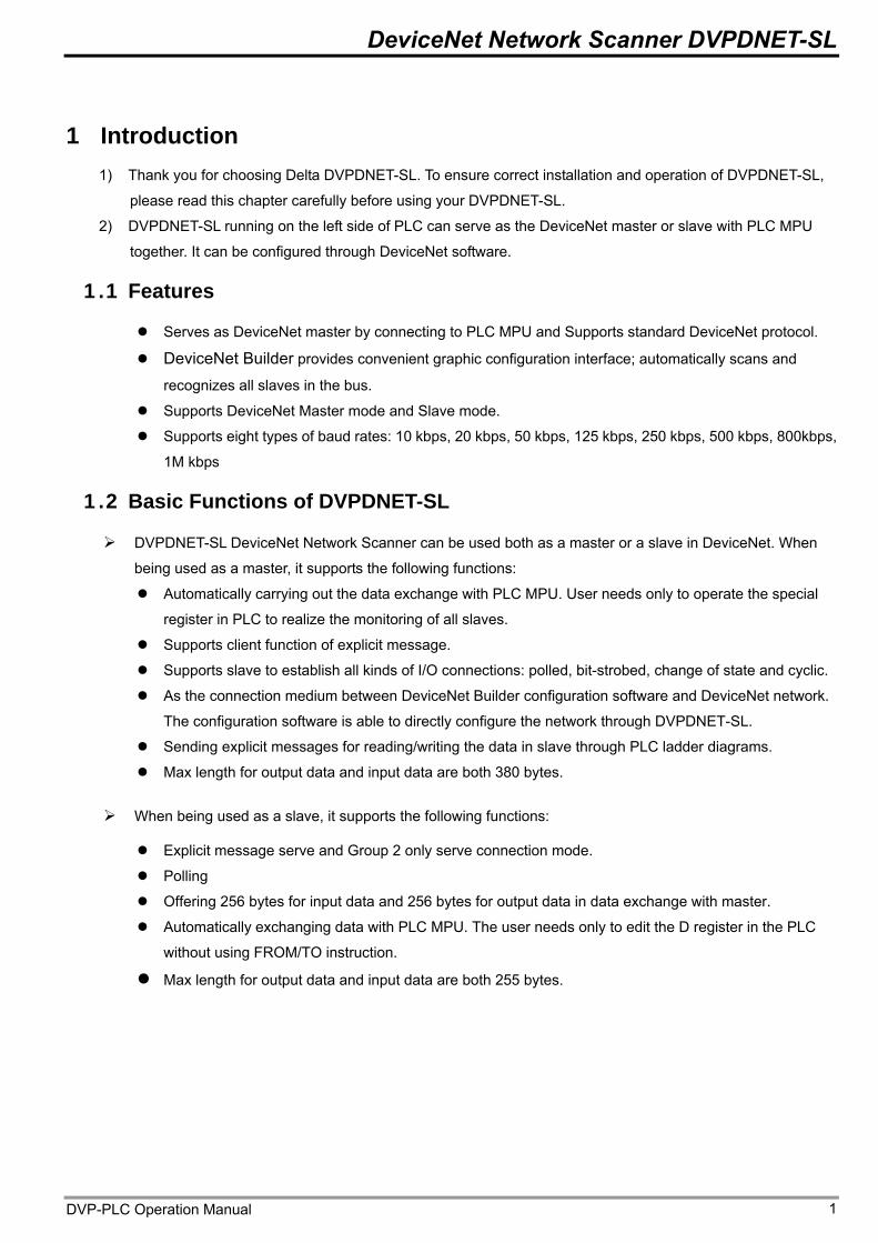
1 Introduction 1) Thank you for choosing Delta DVPDNET-SL. To ensure correct installation and operation of DVPDNET-SL,
please read this chapter carefully before using your DVPDNET-SL.
2) DVPDNET-SL running on the left side of PLC can serve as the DeviceNet master or slave with PLC MPU
together. It can be configured through DeviceNet software.
1.1 Features
Serves as DeviceNet master by connecting to PLC MPU and Supports standard DeviceNet protocol.
DeviceNet Builder provides convenient graphic configuration interface; automatically scans and
recognizes all slaves in the bus.
Supports DeviceNet Master mode and Slave mode.
Supports eight types of baud rates: 10 kbps, 20 kbps, 50 kbps, 125 kbps, 250 kbps, 500 kbps, 800kbps,
1M kbps
1.2 Basic Functions of DVPDNET-SL
DVPDNET-SL DeviceNet Network Scanner can be used both as a master or a slave in DeviceNet. When
being used as a master, it supports the following functions:
Automatically carrying out the data exchange with PLC MPU. User needs only to operate the special
register in PLC to realize the monitoring of all slaves.
Supports client function of explicit message.
Supports slave to establish all kinds of I/O connections: polled, bit-strobed, change of state and cyclic.
As the connection medium between DeviceNet Builder configuration software and DeviceNet network.
The configuration software is able to directly configure the network through DVPDNET-SL.
Sending explicit messages for reading/writing the data in slave through PLC ladder diagrams.
Max length for output data and input data are both 380 bytes.
When being used as a slave, it supports the following functions:
Explicit message serve and Group 2 only serve connection mode.
Polling
Offering 256 bytes for input data and 256 bytes for output data in data exchange with master.
Automatically exchanging data with PLC MPU. The user needs only to edit the D register in the PLC
without using FROM/TO instruction.
Max length for output data and input data are both 255 bytes.
DVP-PLC Operation Manual 1
DeviceNet Network Scanner DVPDNET-SL
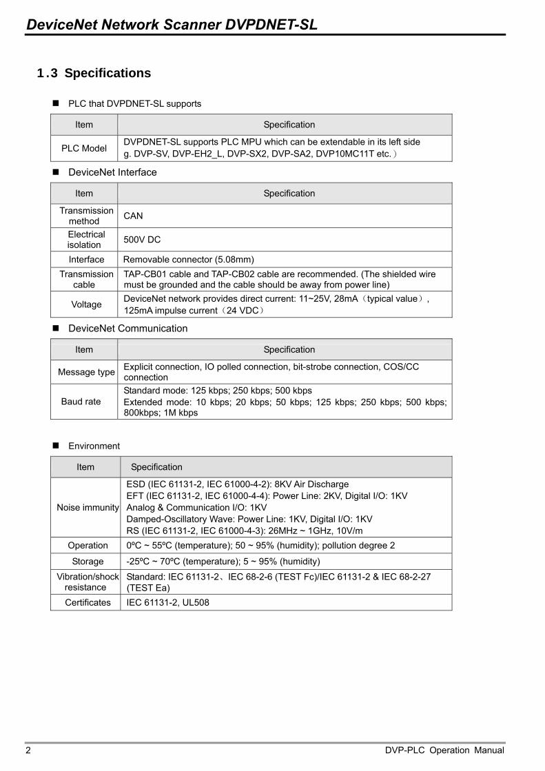
1.3 Specifications
PLC that DVPDNET-SL supports
Item Specification
PLC Model DVPDNET-SL supports PLC MPU which can be extendable in its left side g. DVP-SV, DVP-EH2_L, DVP-SX2, DVP-SA2, DVP10MC11T etc.)
DeviceNet Interface
Item Specification
Transmission method CAN
Electrical isolation 500V DC
Interface Removable connector (5.08mm) Transmission
cable TAP-CB01 cable and TAP-CB02 cable are recommended. (The shielded wire must be grounded and the cable should be away from power line) DeviceNet network provides direct current: 11~25V, 28mA(typical value), 125mA impulse current(24 VDC) Voltage
DeviceNet Communication
Item Specification
Explicit connection, IO polled connection, bit-strobe connection, COS/CC connection Message type
Baud rate Standard mode: 125 kbps; 250 kbps; 500 kbps Extended mode: 10 kbps; 20 kbps; 50 kbps; 125 kbps; 250 kbps; 500 kbps; 800kbps; 1M kbps
Environment
Item Specification
Noise immunity
ESD (IEC 61131-2, IEC 61000-4-2): 8KV Air Discharge EFT (IEC 61131-2, IEC 61000-4-4): Power Line: 2KV, Digital I/O: 1KV Analog & Communication I/O: 1KV Damped-Oscillatory Wave: Power Line: 1KV, Digital I/O: 1KV RS (IEC 61131-2, IEC 61000-4-3): 26MHz ~ 1GHz, 10V/m
Operation 0ºC ~ 55ºC (temperature); 50 ~ 95% (humidity); pollution degree 2
Storage -25ºC ~ 70ºC (temperature); 5 ~ 95% (humidity)
Vibration/shock resistance
Standard: IEC 61131-2、IEC 68-2-6 (TEST Fc)/IEC 61131-2 & IEC 68-2-27 (TEST Ea)
Certificates IEC 61131-2, UL508
DVP-PLC Operation Manual 2
DeviceNet Network Scanner DVPDNET-SL
2 Product Profile & Outline
2.1 Dimension
32
01
4
9
8
6
7 0
MS
NS
5
DR 0DR 1
x10
IN 1IN 0
DVPDNET
x105
32
4
01
8
6
7
9
1
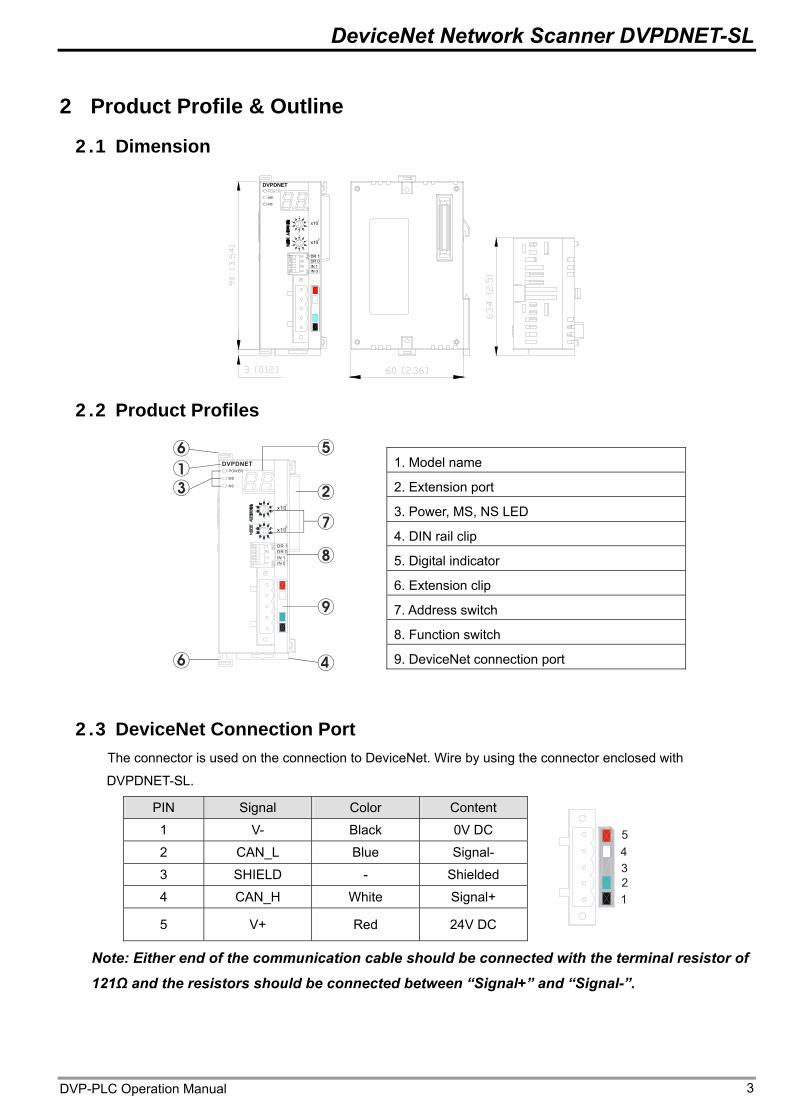
2.2 Product Profiles
1. Model name 2. Extension port 3. Power, MS, NS LED 4. DIN rail clip 5. Digital indicator 6. Extension clip 7. Address switch 8. Function switch 9. DeviceNet connection port
2.3 DeviceNet Connection Port The connector is used on the connection to DeviceNet. Wire by using the connector enclosed with
DVPDNET-SL.
PIN Signal Color Content
1 V- Black 0V DC
2 CAN_L Blue Signal-
3 SHIELD - Shielded
4 CAN_H White Signal+
5 V+ Red 24V DC
12345
Note: Either end of the communication cable should be connected with the terminal resistor of
121Ω and the resistors should be connected between “Signal+” and “Signal-”.
DVP-PLC Operation Manual 3
DeviceNet Network Scanner DVPDNET-SL
2.4 Address Switch
The switch is used on setting up the node address of DVPDNET-SL on DeviceNet. Range: 00 ~ 63 (64 ~ 99
are forbidden).
Switch setting Content
0 … 63 Valid DeviceNet node address
64…99 Invalid DeviceNet node address
91
645
0
091
32
78
2
5 64
3 78
Example: If you need to set the node address of DVPDNET-SL to 26, simply switch the corresponding
switch of x101 to 2 and the corresponding switch of x100 to 6.
Note: Please set up the node address when the power is switched off. After the setup is completed, re-power
DVPDNET-SL. When DVPDNET-SL is operating, changing the setting of node address will be invalid. Use slotted screwdriver to rotate the switch carefully in case you scratch the switch.
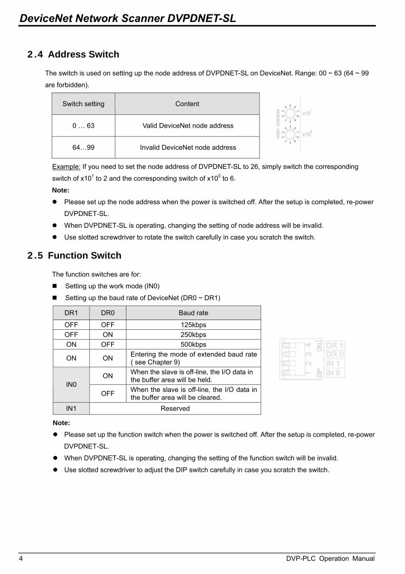
2.5 Function Switch
The function switches are for:
Setting up the work mode (IN0)
Setting up the baud rate of DeviceNet (DR0 ~ DR1)
DR1 DR0 Baud rate
OFF OFF 125kbps OFF ON 250kbps ON OFF 500kbps
ON ON Entering the mode of extended baud rate ( see Chapter 9)
ON When the slave is off-line, the I/O data in the buffer area will be held.
IN0 OFF When the slave is off-line, the I/O data in
the buffer area will be cleared. IN1 Reserved
Note: Please set up the function switch when the power is switched off. After the setup is completed, re-power
DVPDNET-SL. When DVPDNET-SL is operating, changing the setting of the function switch will be invalid. Use slotted screwdriver to adjust the DIP switch carefully in case you scratch the switch.
DVP-PLC Operation Manual 4
DeviceNet Network Scanner DVPDNET-SL
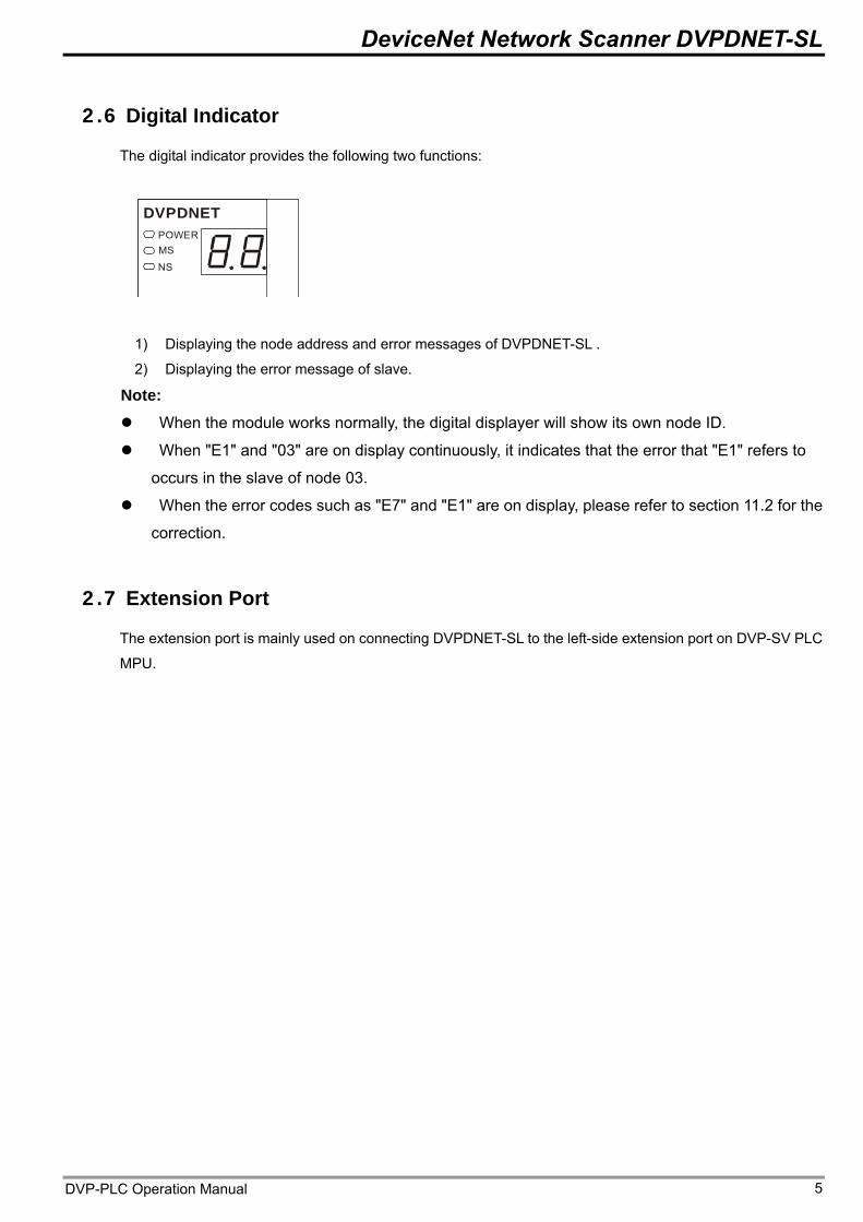
2.6 Digital Indicator
The digital indicator provides the following two functions:
DVPDNETPOWERMS
NS
1) Displaying the node address and error messages of DVPDNET-SL .
2) Displaying the error message of slave.
Note: When the module works normally, the digital displayer will show its own node ID.
When "E1" and "03" are on display continuously, it indicates that the error that "E1" refers to
occurs in the slave of node 03.
When the error codes such as "E7" and "E1" are on display, please refer to section 11.2 for the
correction.
2.7 Extension Port
The extension port is mainly used on connecting DVPDNET-SL to the left-side extension port on DVP-SV PLC
MPU.
DVP-PLC Operation Manual 5
DeviceNet Network Scanner DVPDNET-SL
3 Installation
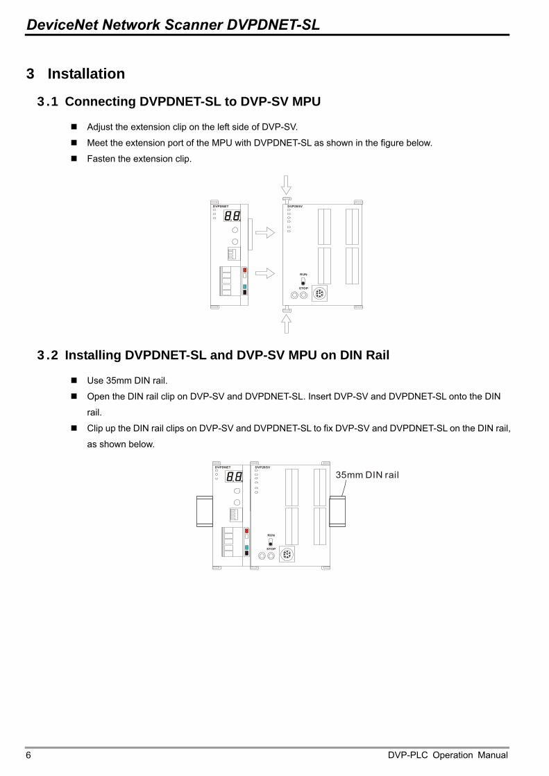
3.1 Connecting DVPDNET-SL to DVP-SV MPU
Adjust the extension clip on the left side of DVP-SV.
Meet the extension port of the MPU with DVPDNET-SL as shown in the figure below.
Fasten the extension clip.
DVPDNET DVP28SV
RUN
STOP
3.2 Installing DVPDNET-SL and DVP-SV MPU on DIN Rail
Use 35mm DIN rail.
Open the DIN rail clip on DVP-SV and DVPDNET-SL. Insert DVP-SV and DVPDNET-SL onto the DIN
rail.
Clip up the DIN rail clips on DVP-SV and DVPDNET-SL to fix DVP-SV and DVPDNET-SL on the DIN rail,
as shown below.
DVPDNET
35mm DIN railDVP28SV
RUN
STOP
DVP-PLC Operation Manual 6
DeviceNet Network Scanner DVPDNET-SL
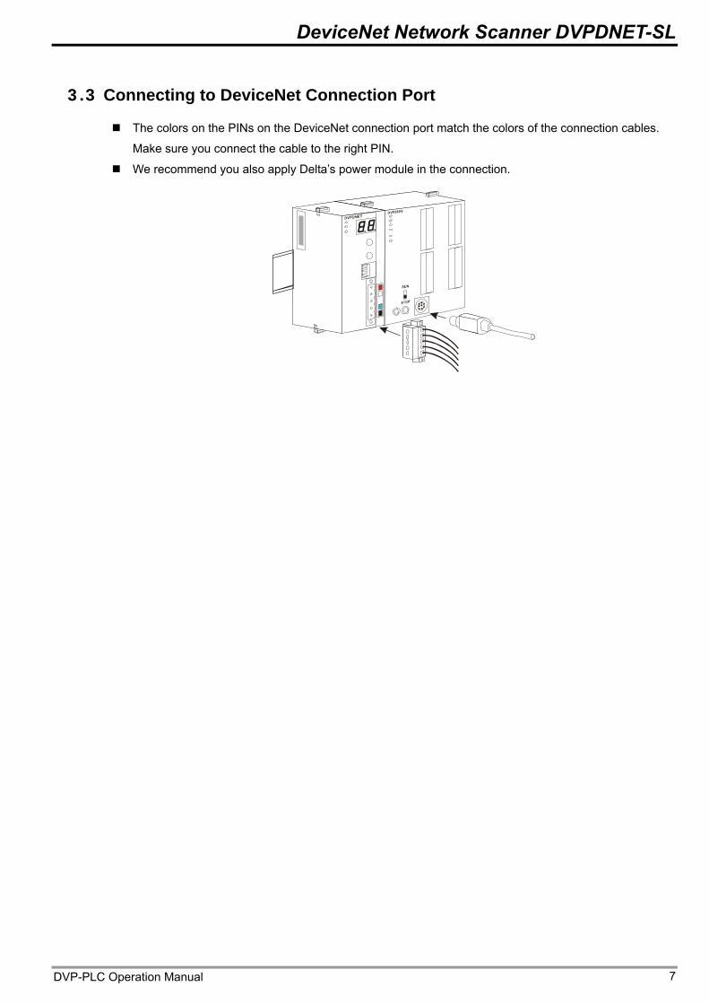
3.3 Connecting to DeviceNet Connection Port
The colors on the PINs on the DeviceNet connection port match the colors of the connection cables.
Make sure you connect the cable to the right PIN.
We recommend you also apply Delta’s power module in the connection.
DVP-PLC Operation Manual 7
DeviceNet Network Scanner DVPDNET-SL
4 Configuration of DVPDNET-SL
4.1 Configuration through DeviceNet Builder Software
Before DVPDNET-SL starts to work normally, it must be configured through DeviceNet Builder
software.
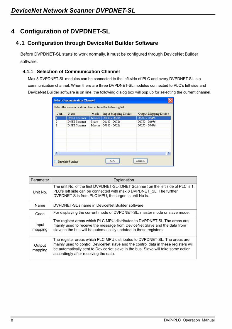
4.1.1 Selection of Communication Channel Max 8 DVPDNET-SL modules can be connected to the left side of PLC and every DVPDNET-SL is a
communication channel. When there are three DVPDNET-SL modules connected to PLC’s left side and
DeviceNet Builder software is on line, the following dialog box will pop up for selecting the current channel.
Parameter Explanation The unit No. of the first DVPDNET-SL(DNET Scanner)on the left side of PLC is 1. PLC’s left side can be connected with max 8 DVPDNET_SL. The further DVPDNET-S is from PLC MPU, the larger its unit No is.
Unit No.
DVPDNET-SL’s name in DeviceNet Builder software. Name
For displaying the current mode of DVPDNET-SL: master mode or slave mode. Code
The register areas which PLC MPU distributes to DVPDNET-SL.The areas are mainly used to receive the message from DeviceNet Slave and the data from slave in the bus will be automatically updated to these registers.
Input mapping
Output mapping
The register areas which PLC MPU distributes to DVPDNET-SL. The areas are mainly used to control DeviceNet slave and the control data in these registers will be automatically sent to DeviceNet slave in the bus. Slave will take some action accordingly after receiving the data.
DVP-PLC Operation Manual 8
DeviceNet Network Scanner DVPDNET-SL
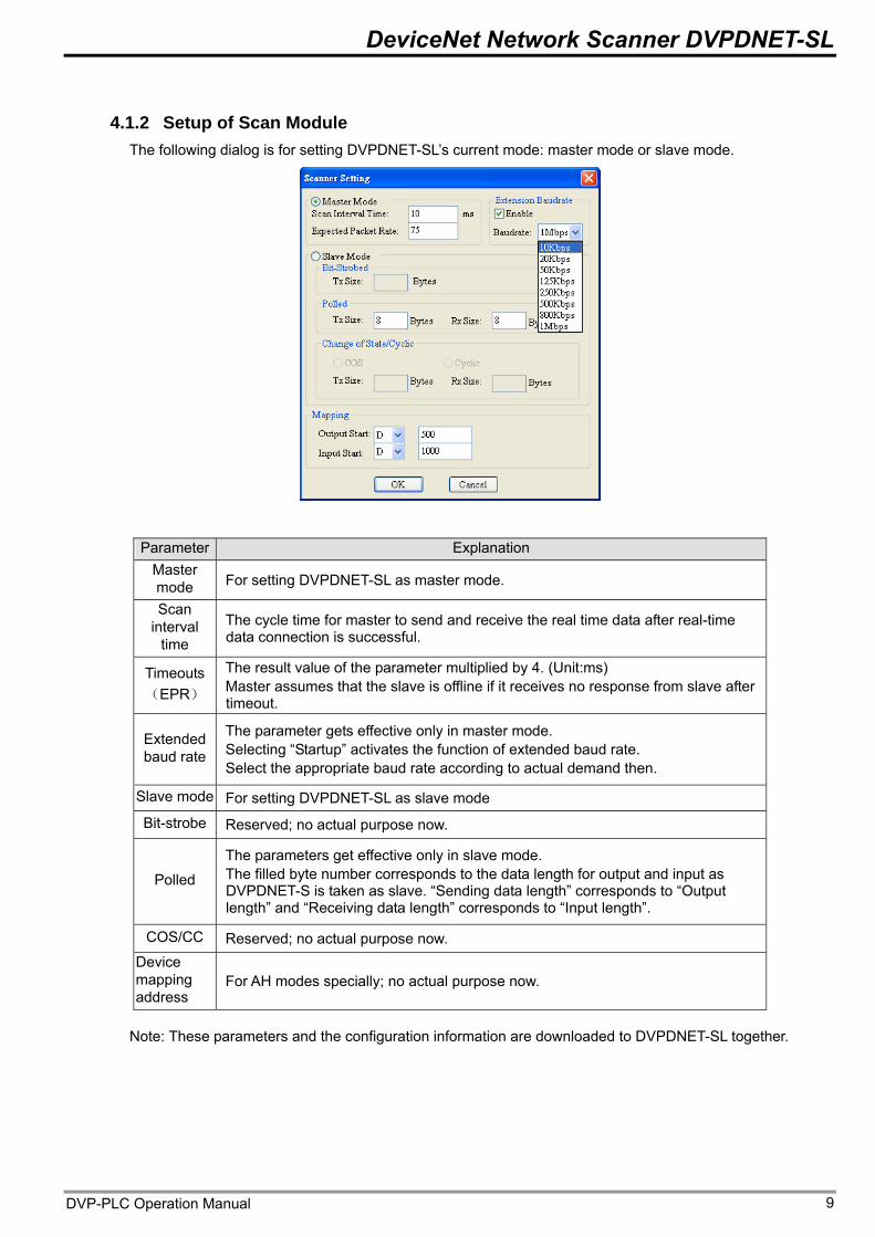
4.1.2 Setup of Scan Module The following dialog is for setting DVPDNET-SL’s current mode: master mode or slave mode.
Parameter Explanation Master mode For setting DVPDNET-SL as master mode.
Scan interval
time The cycle time for master to send and receive the real time data after real-time data connection is successful.
Timeouts (EPR)
The result value of the parameter multiplied by 4. (Unit:ms) Master assumes that the slave is offline if it receives no response from slave after timeout.
Extended baud rate
The parameter gets effective only in master mode. Selecting “Startup” activates the function of extended baud rate. Select the appropriate baud rate according to actual demand then.
Slave mode For setting DVPDNET-SL as slave mode
Bit-strobe Reserved; no actual purpose now.
Polled
The parameters get effective only in slave mode. The filled byte number corresponds to the data length for output and input as DVPDNET-S is taken as slave. “Sending data length” corresponds to “Output length” and “Receiving data length” corresponds to “Input length”.
COS/CC Reserved; no actual purpose now. Device mapping address
For AH modes specially; no actual purpose now.
Note: These parameters and the configuration information are downloaded to DVPDNET-SL together.
DVP-PLC Operation Manual 9
DeviceNet Network Scanner DVPDNET-SL
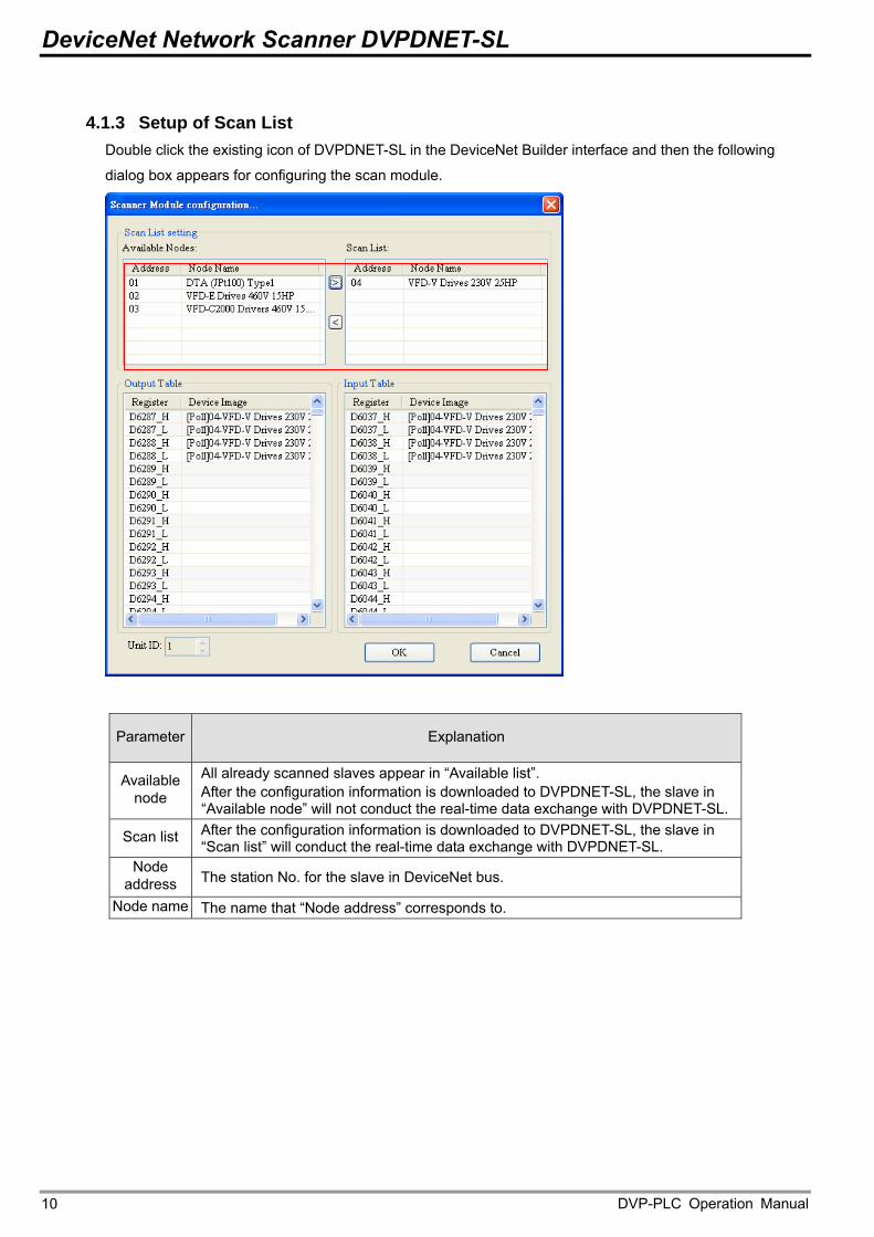
4.1.3 Setup of Scan List Double click the existing icon of DVPDNET-SL in the DeviceNet Builder interface and then the following
dialog box appears for configuring the scan module.
Parameter Explanation
Available node
All already scanned slaves appear in “Available list”. After the configuration information is downloaded to DVPDNET-SL, the slave in “Available node” will not conduct the real-time data exchange with DVPDNET-SL.After the configuration information is downloaded to DVPDNET-SL, the slave in “Scan list” will conduct the real-time data exchange with DVPDNET-SL.
Scan list
Node address The station No. for the slave in DeviceNet bus.
Node name The name that “Node address” corresponds to.
DVP-PLC Operation Manual 10
DeviceNet Network Scanner DVPDNET-SL
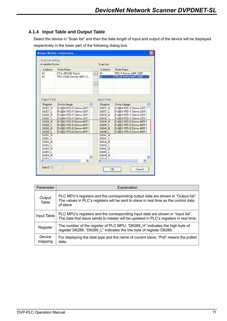
4.1.4 Input Table and Output Table Select the device in “Scan list” and then the data length of input and output of the device will be displayed
respectively in the lower part of the following dialog box.
Parameter Explanation
PLC MPU’s registers and the corresponding output data are shown in “Output list”. The values in PLC’s registers will be sent to slave in real time as the control data of slave.
Output Table
PLC MPU’s registers and the corresponding input data are shown in “input list”. The data that slave sends to master will be updated in PLC’s registers in real time.
Input Table
The number of the register of PLC MPU; “D6289_H” indicates the high byte of register D6289; “D6289_L” indicates the low byte of register D6289.
Register
Device mapping
For displaying the data type and the name of current slave; “Poll” means the polled data.
DVP-PLC Operation Manual 11
DeviceNet Network Scanner DVPDNET-SL
4.2 Data Mapping Areas
The data mapping introduced in this chapter is the data mapping between PLC MPU and DVPDNET-SL. The
mapping relation is unchanged and user has no right to revise this area.
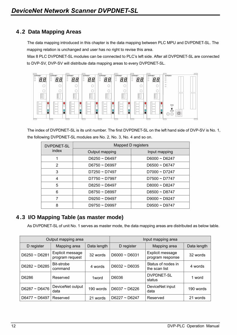
Max 8 PLC DVPDNET-SL modules can be connected to PLC’s left side. After all DVPDNET-SL are connected
to DVP-SV, DVP-SV will distribute data mapping areas to every DVPDNET-SL.
DVPDNET DVP28SV
RUN
STOP
DVPDNETDVPDNETDVPDNETDVPDNETDVPDNETDVPDNETDVPDNET
The index of DVPDNET-SL is its unit number. The first DVPDNET-SL on the left hand side of DVP-SV is No. 1,
the following DVPDNET-SL modules are No. 2, No. 3, No. 4 and so on.
Mapped D registers DVPDNET-SL index Output mapping Input mapping
1 D6250 ~ D6497 D6000 ~ D6247
2 D6750 ~ D6997 D6500 ~ D6747
3 D7250 ~ D7497 D7000 ~ D7247
4 D7750 ~ D7997 D7500 ~ D7747
5 D8250 ~ D8497 D8000 ~ D8247
6 D8750 ~ D8997 D8500 ~ D8747
7 D9250 ~ D9497 D9000 ~ D9247
8 D9750 ~ D9997 D9500 ~ D9747
4.3 I/O Mapping Table (as master mode) As DVPDNET-SL of unit No. 1 serves as master mode, the data mapping areas are distributed as below table.
Output mapping area Input mapping area
D register Mapping area Data length D register Mapping area Data length
D6250 ~ D6281 Explicit message program request 32 words D6000 ~ D6031 Explicit message
program response 32 words
D6282 ~ D6285 Bit-strobe command 4 words D6032 ~ D6035 Status of nodes in
the scan list 4 words
D6286 Reserved 1word D6036 DVPDNET-SL status 1 word
D6287 ~ D6476 DeviceNet output data 190 words D6037 ~ D6226 DeviceNet input
data 190 words
D6477 ~ D6497 Reserved 21 words D6227 ~ D6247 Reserved 21 words
DVP-PLC Operation Manual 12
DeviceNet Network Scanner DVPDNET-SL
Note: If the unit No. is 2, the number of the registers above will all be added by 500 respectively; if the unit No.
is 3, the number of the registers above will all be added by 1000 respectively; if the unit No. is 4, the number of
the registers above will all be added by 1500 respectively and so on.
4.4 I/O Mapping Table (as slave mode) As DVPDNET-SL serves as slave mode, the data mapping areas are distributed as below table and these
registers are applied for real-time data exchange.
Input mapping area Output mapping area
Unit No. Initial register Max data length Initial register Max data length
1 D6000 255Bytes D6250 255Bytes 2 D6500 255Bytes D6750 255Bytes 3 D7000 255Bytes D7250 255Bytes 4 D7500 255Bytes D7750 255Bytes 5 D8000 255Bytes D8250 255Bytes 6 D8500 255Bytes D8750 255Bytes 7 D9000 255Bytes D9250 255Bytes 8 D9500 255Bytes D9750 255Bytes
When the unit No. of DVPDNET_SL is 1, the control data which DeviceNet sends out will be updated in real
time in the registers of PLC MPU with D6000 as the initial register. In the meanwhile, the value in the registers
of PLC MPU with D6250 as the initial register will be automatically sent back to DeviceNet master so as to
realize the real-time data exchange.
DVP-PLC Operation Manual 13
DeviceNet Network Scanner DVPDNET-SL
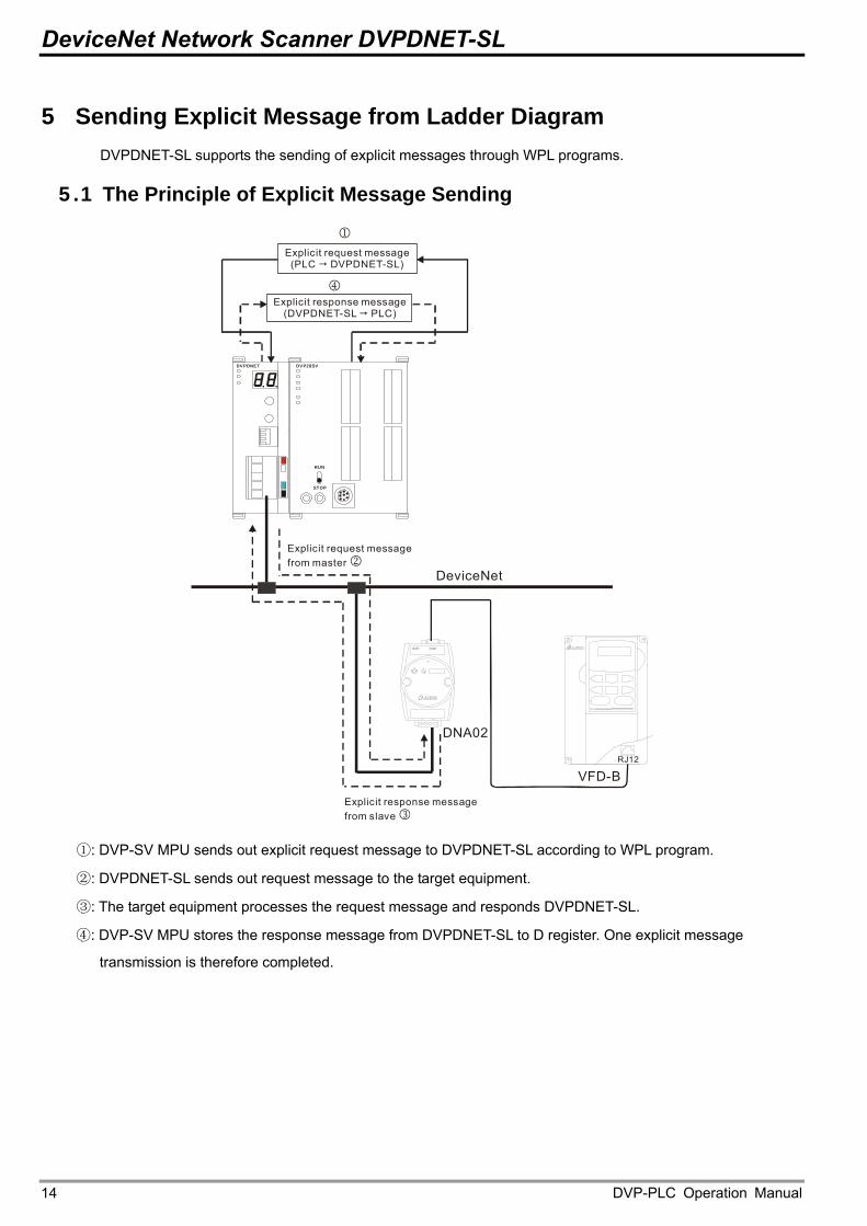
5 Sending Explicit Message from Ladder Diagram DVPDNET-SL supports the sending of explicit messages through WPL programs.
5.1 The Principle of Explicit Message Sending
DVPDNET DVP28SV
RUN
STOP
DeviceNet
RJ12
1
4
VFD-B
DNA02
Explicit request message(PLC DVPDNET-SL)
Explicit response message (DVPDNET-SL PLC)
Explicit request messagefrom master 2
Explicit response messagefrom slave 3
①: DVP-SV MPU sends out explicit request message to DVPDNET-SL according to WPL program.
②: DVPDNET-SL sends out request message to the target equipment.
③: The target equipment processes the request message and responds DVPDNET-SL.
④: DVP-SV MPU stores the response message from DVPDNET-SL to D register. One explicit message
transmission is therefore completed.
DVP-PLC Operation Manual 14
DeviceNet Network Scanner DVPDNET-SL
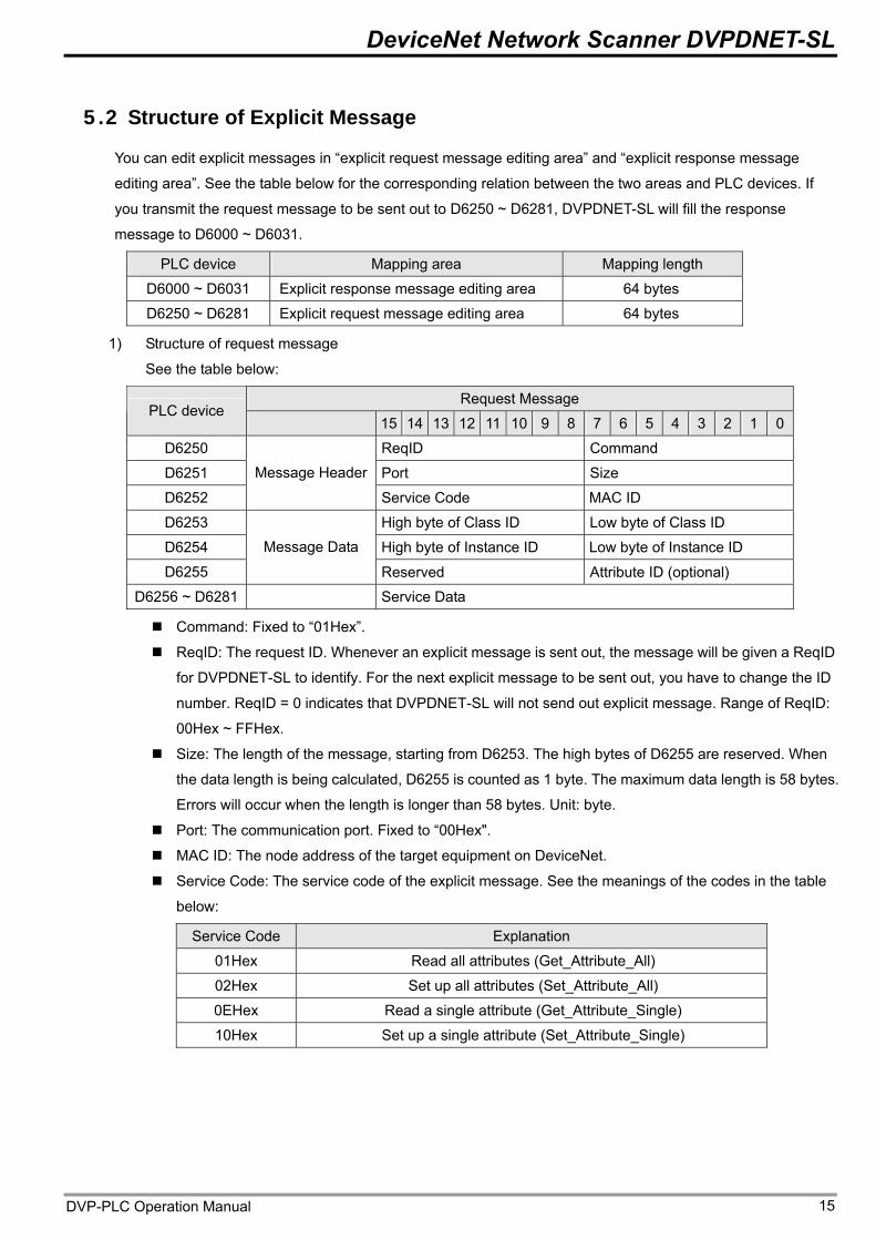
5.2 Structure of Explicit Message
You can edit explicit messages in “explicit request message editing area” and “explicit response message
editing area”. See the table below for the corresponding relation between the two areas and PLC devices. If
you transmit the request message to be sent out to D6250 ~ D6281, DVPDNET-SL will fill the response
message to D6000 ~ D6031.
PLC device Mapping area Mapping length
D6000 ~ D6031 Explicit response message editing area 64 bytes
D6250 ~ D6281 Explicit request message editing area 64 bytes
1) Structure of request message
See the table below:
Request Message PLC device
15 14 13 12 11 10 9 8 7 6 5 4 3 2 1 0
D6250 ReqID Command
D6251 Port Size
D6252
Message Header
Service Code MAC ID
D6253 High byte of Class ID Low byte of Class ID
D6254 High byte of Instance ID Low byte of Instance ID
D6255
Message Data
Reserved Attribute ID (optional)
D6256 ~ D6281 Service Data
Command: Fixed to “01Hex”.
ReqID: The request ID. Whenever an explicit message is sent out, the message will be given a ReqID
for DVPDNET-SL to identify. For the next explicit message to be sent out, you have to change the ID
number. ReqID = 0 indicates that DVPDNET-SL will not send out explicit message. Range of ReqID:
00Hex ~ FFHex.
Size: The length of the message, starting from D6253. The high bytes of D6255 are reserved. When
the data length is being calculated, D6255 is counted as 1 byte. The maximum data length is 58 bytes.
Errors will occur when the length is longer than 58 bytes. Unit: byte.
Port: The communication port. Fixed to “00Hex".
MAC ID: The node address of the target equipment on DeviceNet.
Service Code: The service code of the explicit message. See the meanings of the codes in the table
below:
Service Code Explanation
01Hex Read all attributes (Get_Attribute_All)
02Hex Set up all attributes (Set_Attribute_All)
0EHex Read a single attribute (Get_Attribute_Single)
10Hex Set up a single attribute (Set_Attribute_Single)
DVP-PLC Operation Manual 15
DeviceNet Network Scanner DVPDNET-SL
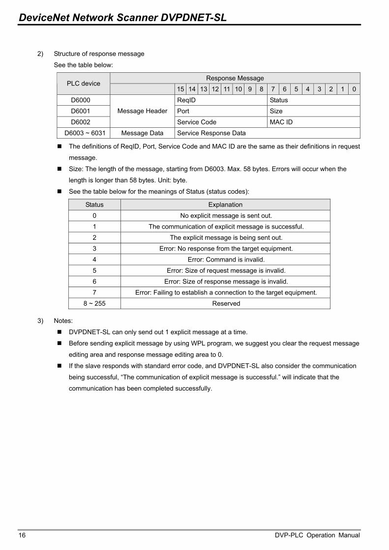
2) Structure of response message
See the table below:
Response Message PLC device
15 14 13 12 11 10 9 8 7 6 5 4 3 2 1 0
D6000 ReqID Status
D6001 Port Size
D6002
Message Header
Service Code MAC ID
D6003 ~ 6031 Message Data Service Response Data
The definitions of ReqID, Port, Service Code and MAC ID are the same as their definitions in request
message.
Size: The length of the message, starting from D6003. Max. 58 bytes. Errors will occur when the
length is longer than 58 bytes. Unit: byte.
See the table below for the meanings of Status (status codes):
Status Explanation
0 No explicit message is sent out.
1 The communication of explicit message is successful.
2 The explicit message is being sent out.
3 Error: No response from the target equipment.
4 Error: Command is invalid.
5 Error: Size of request message is invalid.
6 Error: Size of response message is invalid.
7 Error: Failing to establish a connection to the target equipment.
8 ~ 255 Reserved
3) Notes:
DVPDNET-SL can only send out 1 explicit message at a time.
Before sending explicit message by using WPL program, we suggest you clear the request message
editing area and response message editing area to 0.
If the slave responds with standard error code, and DVPDNET-SL also consider the communication
being successful, “The communication of explicit message is successful.” will indicate that the
communication has been completed successfully.
DVP-PLC Operation Manual 16
DeviceNet Network Scanner DVPDNET-SL
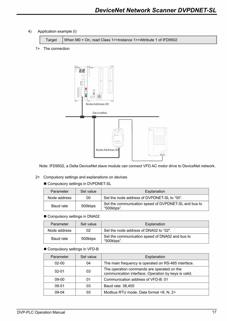
4) Application example (I)
Target When M0 = On, read Class 1>>Instance 1>>Attribute 1 of IFD9502
1> The connection
DVPDNET DVP28S V
RU N
STOP
DeviceNet
RJ12
Node Address:00
Node Address:02
Note: IFD9502, a Delta DeviceNet slave module can connect VFD AC motor drive to DeviceNet network.
2> Compulsory settings and explanations on devices
Compulsory settings in DVPDNET-SL
Parameter Set value Explanation
Node address 00 Set the node address of DVPDNET-SL to “00”. Set the communication speed of DVPDNET-SL and bus to “500kbps”. Baud rate 500kbps
Compulsory settings in DNA02
Parameter Set value Explanation
Node address 02 Set the node address of DNA02 to “02". Set the communication speed of DNA02 and bus to “500kbps”. Baud rate 500kbps
Compulsory settings in VFD-B
Parameter Set value Explanation
02-00 04 The main frequency is operated on RS-485 interface.
02-01 03 The operation commands are operated on the communication interface. Operation by keys is valid.
09-00 01 Communication address of VFD-B: 01
09-01 03 Baud rate: 38,400
09-04 03 Modbus RTU mode. Data format <8, N, 2>
DVP-PLC Operation Manual 17
DeviceNet Network Scanner DVPDNET-SL
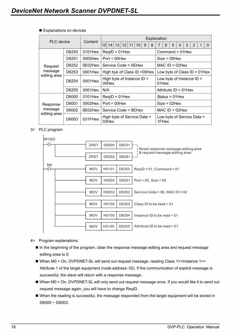
Explanations on devices
Explanation PLC device Content
15 14 13 12 11 10 9 8 7 6 5 4 3 2 1 0
D6250 0101Hex ReqID = 01Hex Command = 01Hex
D6251 0005Hex Port = 00Hex Size = 05Hex
D6252 0E02Hex Service Code = 0EHex MAC ID = 02Hex
D6253 0001Hex High bye of Class ID =00Hex Low byte of Class ID = 01Hex
D6254 0001Hex High byte of Instance ID = 00Hex
Low byte of Instance ID = 01Hex
Request message
editing area
D6255 0001Hex N/A Attribute ID = 01Hex
D6000 0101Hex ReqID = 01Hex Status = 01Hex
D6001 0002Hex Port = 00Hex Size = 02Hex
D6002 8E02Hex Service Code = 8EHex MAC ID = 02Hex Response message
editing area D6003 031FHex High byte of Service Data =
03Hex Low byte of Service Data = 1FHex
3> PLC program
MOV H0101 D6250
M1002
ZRST D6250 D6281
M0
MOV H0005 D6251
MOV H0E02 D6252
MOV H0100 D6253
MOV H0100 D6254
MOV H0100 D6255
ZRST D6000 D6031Reset response message editing area& request message editing area
ReqID = 01, Command = 01
Port = 00, Size = 05
Service Code = 0E, MAC ID = 02
Class ID to be read = 01
Instance ID to be read = 01
Attribute ID to be read = 01
4> Program explanations:
In the beginning of the program, clear the response message editing area and request message
editing area to 0.
When M0 = On, DVPDNET-SL will send out request message, reading Class 1>>Instance 1>>
Attribute 1 of the target equipment (node address: 02). If the communication of explicit message is
successful, the slave will return with a response message.
When M0 = On, DVPDNET-SL will only send out request message once. If you would like it to send out
request message again, you will have to change ReqID.
When the reading is successful, the message responded from the target equipment will be stored in
D6000 ~ D6003.
DVP-PLC Operation Manual 18
DeviceNet Network Scanner DVPDNET-SL
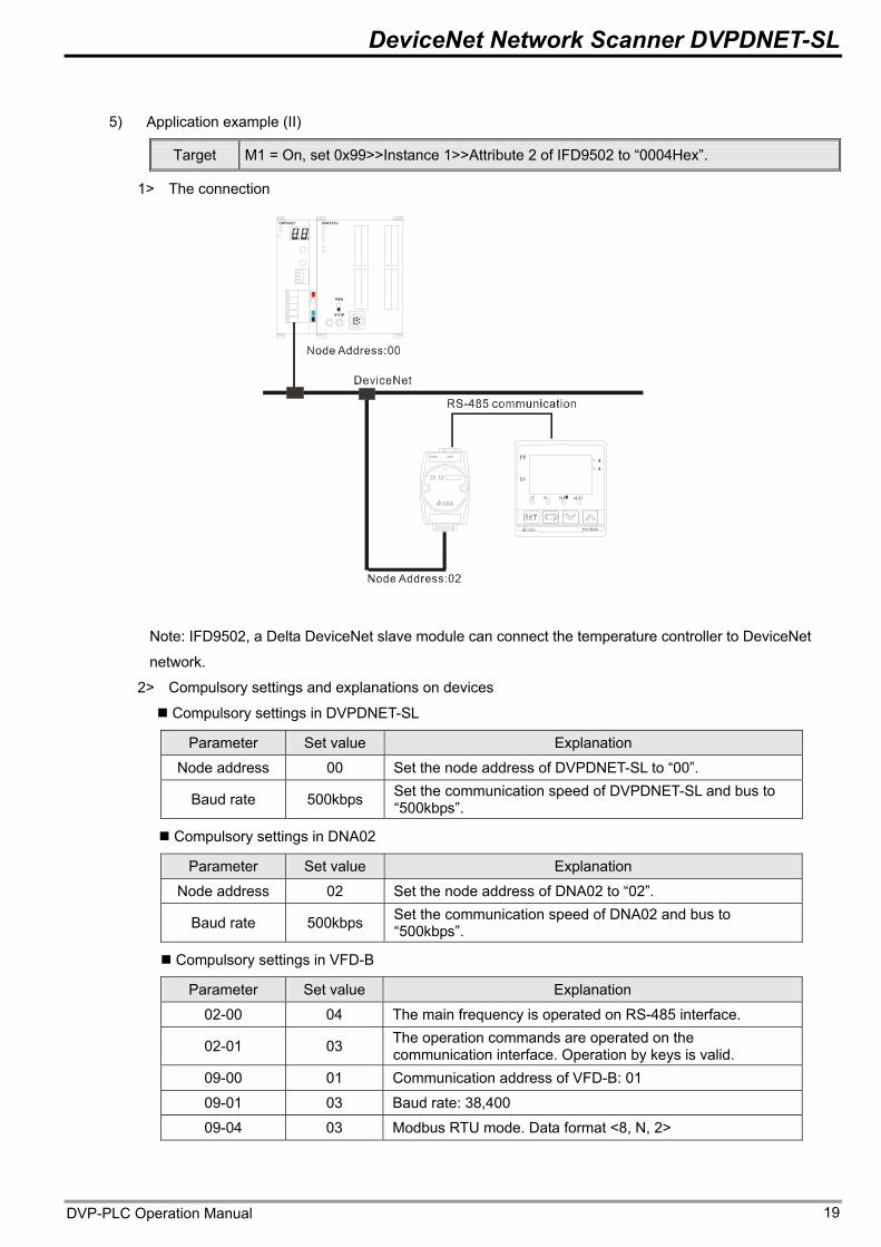
5) Application example (II)
Target M1 = On, set 0x99>>Instance 1>>Attribute 2 of IFD9502 to “0004Hex”.
1> The connection
Note: IFD9502, a Delta DeviceNet slave module can connect the temperature controller to DeviceNet
network.
2> Compulsory settings and explanations on devices
Compulsory settings in DVPDNET-SL
Parameter Set value Explanation
Node address 00 Set the node address of DVPDNET-SL to “00”. Set the communication speed of DVPDNET-SL and bus to “500kbps”. Baud rate 500kbps
Compulsory settings in DNA02
Parameter Set value Explanation
Node address 02 Set the node address of DNA02 to “02”. Set the communication speed of DNA02 and bus to “500kbps”. Baud rate 500kbps
Compulsory settings in VFD-B
Parameter Set value Explanation
02-00 04 The main frequency is operated on RS-485 interface.
02-01 03 The operation commands are operated on the communication interface. Operation by keys is valid.
09-00 01 Communication address of VFD-B: 01
09-01 03 Baud rate: 38,400
09-04 03 Modbus RTU mode. Data format <8, N, 2>
DVP-PLC Operation Manual 19
DeviceNet Network Scanner DVPDNET-SL
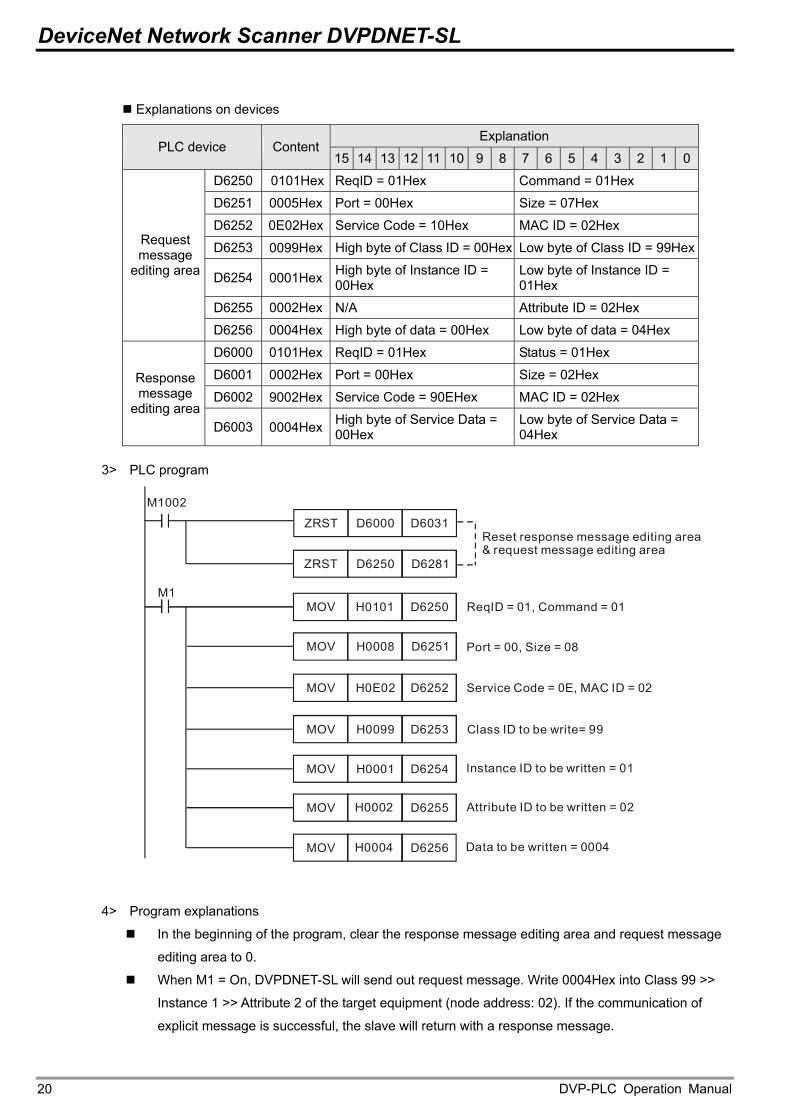
Explanations on devices
Explanation PLC device Content
15 14 13 12 11 10 9 8 7 6 5 4 3 2 1 0
D6250 0101Hex ReqID = 01Hex Command = 01Hex
D6251 0005Hex Port = 00Hex Size = 07Hex
D6252 0E02Hex Service Code = 10Hex MAC ID = 02Hex
D6253 0099Hex High byte of Class ID = 00Hex Low byte of Class ID = 99Hex
D6254 0001Hex High byte of Instance ID = 00Hex
Low byte of Instance ID = 01Hex
D6255 0002Hex N/A Attribute ID = 02Hex
Request message
editing area
D6256 0004Hex High byte of data = 00Hex Low byte of data = 04Hex
D6000 0101Hex ReqID = 01Hex Status = 01Hex
D6001 0002Hex Port = 00Hex Size = 02Hex
D6002 9002Hex Service Code = 90EHex MAC ID = 02Hex Response message
editing area D6003 0004Hex High byte of Service Data =
00Hex Low byte of Service Data = 04Hex
3> PLC program
MOV H0101 D6250
M1002
ZRST D6250 D6281
M1
MOV H0008 D6251
MOV H0E02 D6252
MOV H0099 D6253
MOV H0001 D6254
MOV H0002 D6255
ZRST D6000 D6031Reset response message editing area& request message editing area
ReqID = 01, Command = 01
Port = 00, Size = 08
Service Code = 0E, MAC ID = 02
Class ID to be write= 99
Instance ID to be = 01written
Attribute ID to be = 02written
MOV H0004 D6256 Data to be written = 0004
4> Program explanations
In the beginning of the program, clear the response message editing area and request message
editing area to 0.
When M1 = On, DVPDNET-SL will send out request message. Write 0004Hex into Class 99 >>
Instance 1 >> Attribute 2 of the target equipment (node address: 02). If the communication of
explicit message is successful, the slave will return with a response message.
DVP-PLC Operation Manual 20
DeviceNet Network Scanner DVPDNET-SL
When M1 = On, DVPDNET-SL will only send out request message once. If you would like it to
send out request message again, you will have to change ReqID.
When the writing is successfully done, the message responded from the target equipment will be
stored in D6000 ~ D6003.
DVP-PLC Operation Manual 21
DeviceNet Network Scanner DVPDNET-SL
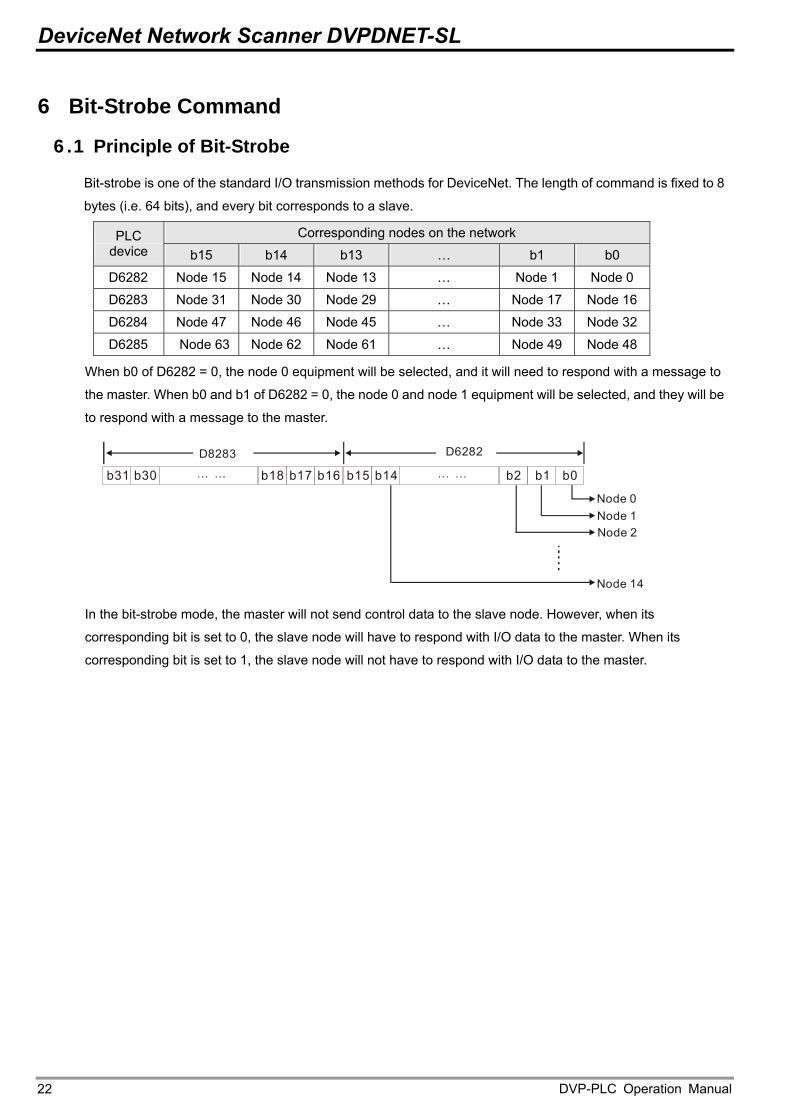
6 Bit-Strobe Command
6.1 Principle of Bit-Strobe
Bit-strobe is one of the standard I/O transmission methods for DeviceNet. The length of command is fixed to 8
bytes (i.e. 64 bits), and every bit corresponds to a slave.
Corresponding nodes on the network PLC device b15 b14 b13 … b1 b0
D6282 Node 15 Node 14 Node 13 … Node 1 Node 0
D6283 Node 31 Node 30 Node 29 … Node 17 Node 16
D6284 Node 47 Node 46 Node 45 … Node 33 Node 32
D6285 Node 63 Node 62 Node 61 … Node 49 Node 48
When b0 of D6282 = 0, the node 0 equipment will be selected, and it will need to respond with a message to
the master. When b0 and b1 of D6282 = 0, the node 0 and node 1 equipment will be selected, and they will be
to respond with a message to the master.
b0b1b17 b15 b14b30 b2b18 b16b31
D8283
Node 0Node 1Node 2
Node 14
D6282
In the bit-strobe mode, the master will not send control data to the slave node. However, when its
corresponding bit is set to 0, the slave node will have to respond with I/O data to the master. When its
corresponding bit is set to 1, the slave node will not have to respond with I/O data to the master.
DVP-PLC Operation Manual 22
DeviceNet Network Scanner DVPDNET-SL
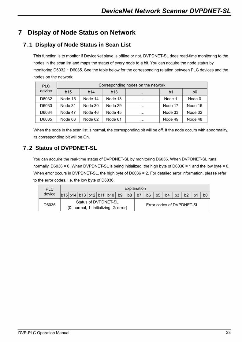
7 Display of Node Status on Network
7.1 Display of Node Status in Scan List
This function is to monitor if DeviceNet slave is offline or not. DVPDNET-SL does read-time monitoring to the
nodes in the scan list and maps the status of every node to a bit. You can acquire the node status by
monitoring D6032 ~ D6035. See the table below for the corresponding relation between PLC devices and the
nodes on the network:
Corresponding nodes on the network PLC device b15 b14 b13 … b1 b0
D6032 Node 15 Node 14 Node 13 … Node 1 Node 0
D6033 Node 31 Node 30 Node 29 … Node 17 Node 16
D6034 Node 47 Node 46 Node 45 … Node 33 Node 32
D6035 Node 63 Node 62 Node 61 … Node 49 Node 48
When the node in the scan list is normal, the corresponding bit will be off. If the node occurs with abnormality,
its corresponding bit will be On.
7.2 Status of DVPDNET-SL
You can acquire the real-time status of DVPDNET-SL by monitoring D6036. When DVPDNET-SL runs
normally, D6036 = 0. When DVPDNET-SL is being initialized, the high byte of D6036 = 1 and the low byte = 0.
When error occurs in DVPDNET-SL, the high byte of D6036 = 2. For detailed error information, please refer
to the error codes, i.e. the low byte of D6036.
Explanation PLC device b15 b14 b13 b12 b11 b10 b9 b8 b7 b6 b5 b4 b3 b2 b1 b0
D6036 Status of DVPDNET-SL
(0: normal, 1: initializing, 2: error) Error codes of DVPDNET-SL
DVP-PLC Operation Manual 23
DeviceNet Network Scanner DVPDNET-SL
8 Setup of Slave Mode DVPDNET-SL can serve as slave through modifying of the mode by software. As DVPDNET-SL serves as slave,
the default input / output data length is 8 bytes and max input / output data length is 255 bytes.
DVPDNET-SL can be set as slave mode in the following method.
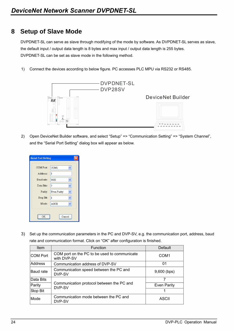
1) Connect the devices according to below figure. PC accesses PLC MPU via RS232 or RS485.
DVP28SVDVPDNET-SL
DeviceNet Builder
2) Open DeviceNet Builder software, and select “Setup” => “Communication Setting” => “System Channel”,
and the “Serial Port Setting” dialog box will appear as below.
3) Set up the communication parameters in the PC and DVP-SV, e.g. the communication port, address, baud
rate and communication format. Click on “OK” after configuration is finished. Item Function Default
COM Port COM port on the PC to be used to communicate with DVP-SV
COM1
Address Communication address of DVP-SV 01
Baud rate Communication speed between the PC and DVP-SV
9,600 (bps)
Data Bits 7 Parity Even Parity Stop Bit
Communication protocol between the PC and DVP-SV
1
Mode Communication mode between the PC and DVP-SV
ASCII
DVP-PLC Operation Manual 24
DeviceNet Network Scanner DVPDNET-SL
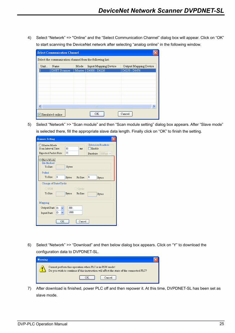
4) Select “Network” => "Online” and the “Select Communication Channel” dialog box will appear. Click on “OK”
to start scanning the DeviceNet network after selecting “analog online” in the following window.
5) Select “Network” >> “Scan module” and then “Scan module setting” dialog box appears. After “Slave mode”
is selected there, fill the appropriate slave data length. Finally click on “OK” to finish the setting.
6) Select “Network” >> “Download” and then below dialog box appears. Click on “Y” to download the
configuration data to DVPDNET-SL.
7) After download is finished, power PLC off and then repower it. At this time, DVPDNET-SL has been set as
slave mode.
DVP-PLC Operation Manual 25
DeviceNet Network Scanner DVPDNET-SL
9 Setup of Extended Baud Rate
9.1 Setup of Extended Baud Rate (as master mode)
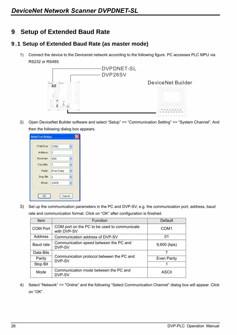
1) Connect the device to the Devicenet network according to the following figure. PC accesses PLC MPU via
RS232 or RS485.
DVP28SVDVPDNET-SL
DeviceNet Builder
2) Open DeviceNet Builder software and select “Setup” => “Communication Setting” => “System Channel”. And
then the following dialog box appears.
3) Set up the communication parameters in the PC and DVP-SV, e.g. the communication port, address, baud
rate and communication format. Click on “OK” after configuration is finished. Item Function Default
COM Port COM port on the PC to be used to communicate with DVP-SV
COM1
Address Communication address of DVP-SV 01
Baud rate Communication speed between the PC and DVP-SV
9,600 (bps)
Data Bits 7 Parity Even Parity
Stop Bit
Communication protocol between the PC and DVP-SV
1
Mode Communication mode between the PC and DVP-SV
ASCII
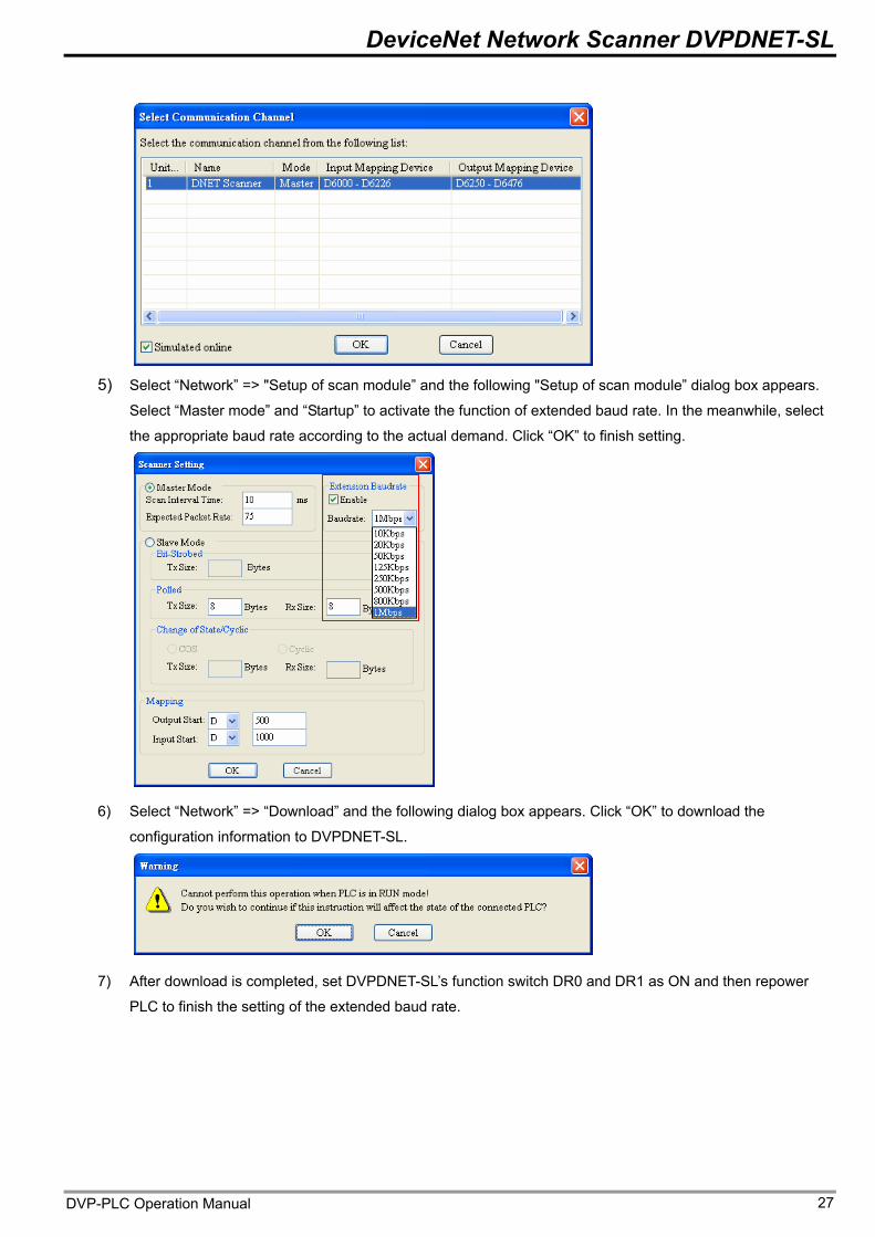
4) Select “Network” => "Online” and the following “Select Communication Channel” dialog box will appear. Click
on “OK”.
DVP-PLC Operation Manual 26
DeviceNet Network Scanner DVPDNET-SL
5) Select “Network” => "Setup of scan module” and the following "Setup of scan module” dialog box appears.
Select “Master mode” and “Startup” to activate the function of extended baud rate. In the meanwhile, select
the appropriate baud rate according to the actual demand. Click “OK” to finish setting.
6) Select “Network” => “Download” and the following dialog box appears. Click “OK” to download the
configuration information to DVPDNET-SL.
7) After download is completed, set DVPDNET-SL’s function switch DR0 and DR1 as ON and then repower
PLC to finish the setting of the extended baud rate.
DVP-PLC Operation Manual 27
DeviceNet Network Scanner DVPDNET-SL
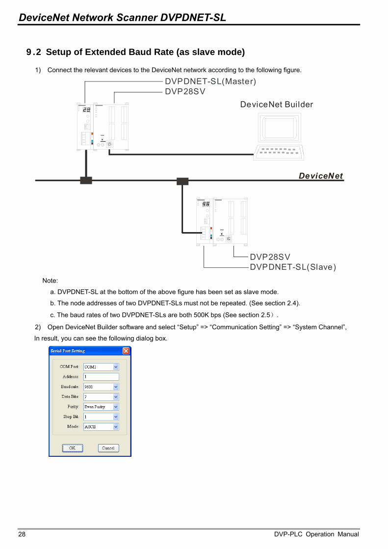
9.2 Setup of Extended Baud Rate (as slave mode)
1) Connect the relevant devices to the DeviceNet network according to the following figure.
DVP28SVDVPDNET-SL(Master)
DeviceNet Builder
DeviceNet
DVP28SVDVPDNET-SL(Slave)
Note:
a. DVPDNET-SL at the bottom of the above figure has been set as slave mode.
b. The node addresses of two DVPDNET-SLs must not be repeated. (See section 2.4).
c. The baud rates of two DVPDNET-SLs are both 500K bps (See section 2.5). 2) Open DeviceNet Builder software and select “Setup” => “Communication Setting” => “System Channel”,
In result, you can see the following dialog box.
DVP-PLC Operation Manual 28
DeviceNet Network Scanner DVPDNET-SL
3) Set up the communication parameters in the PC and DVP-SV, e.g. the communication port, address, baud
rate and communication format. Click on “OK” after configuration is finished.
Item Function Default
COM Port COM port on the PC to be used to communicate with DVP-SV
COM1
Address Communication address of DVP-SV 01
Baud rate Communication speed between the PC and DVP-SV
9,600 (bps)
Data Bits 7 Parity Even Parity
Stop Bit
Communication protocol between the PC and DVP-SV
1
Mode Communication mode between the PC and DVP-SV
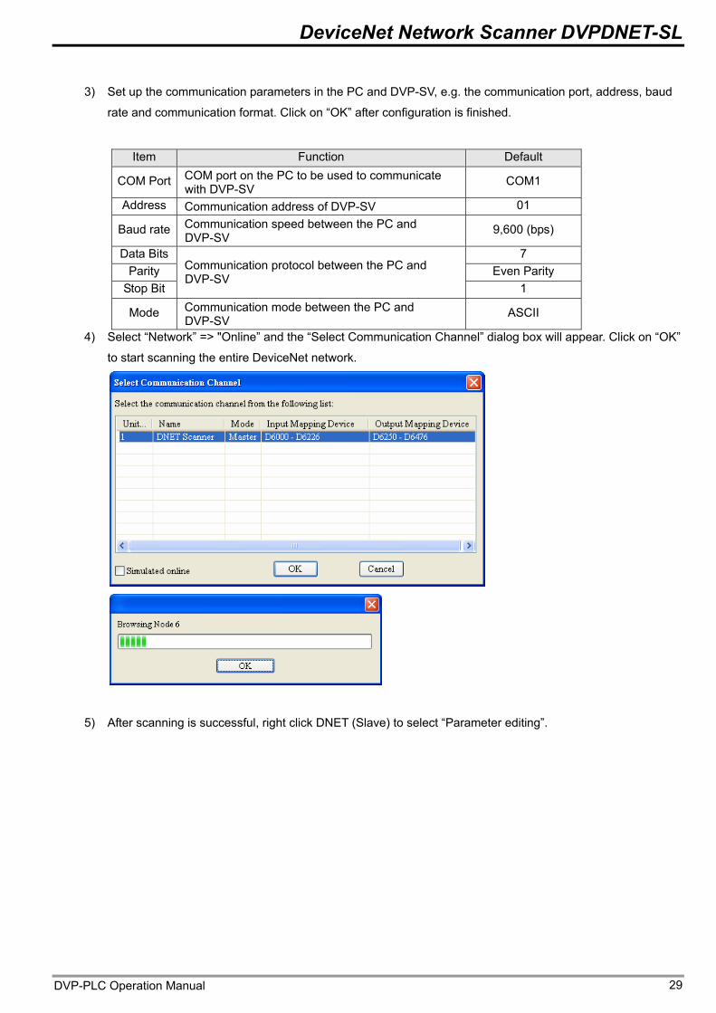
ASCII 4) Select “Network” => "Online” and the “Select Communication Channel” dialog box will appear. Click on “OK”
to start scanning the entire DeviceNet network.
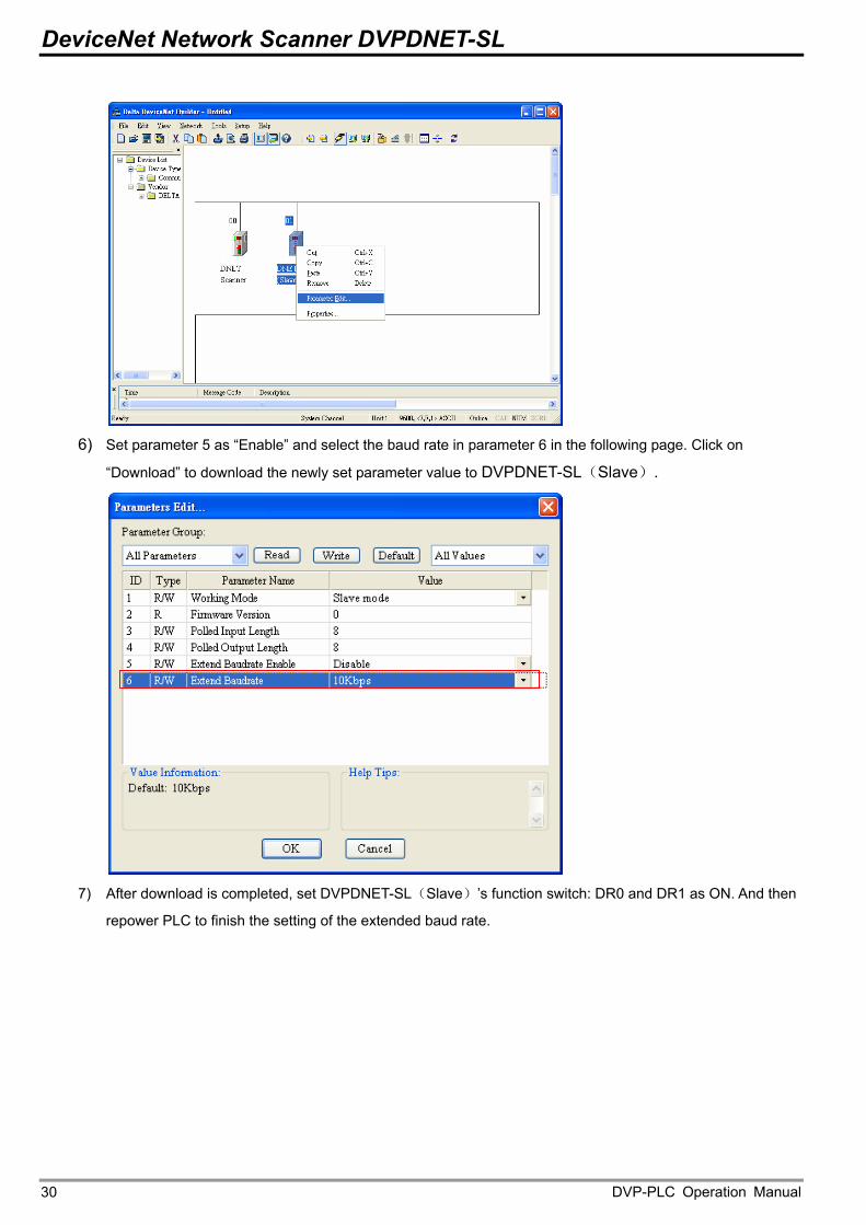
5) After scanning is successful, right click DNET (Slave) to select “Parameter editing”.
DVP-PLC Operation Manual 29
DeviceNet Network Scanner DVPDNET-SL
6) Set parameter 5 as “Enable” and select the baud rate in parameter 6 in the following page. Click on
“Download” to download the newly set parameter value to DVPDNET-SL(Slave).
7) After download is completed, set DVPDNET-SL(Slave)’s function switch: DR0 and DR1 as ON. And then
repower PLC to finish the setting of the extended baud rate.
DVP-PLC Operation Manual 30
DeviceNet Network Scanner DVPDNET-SL
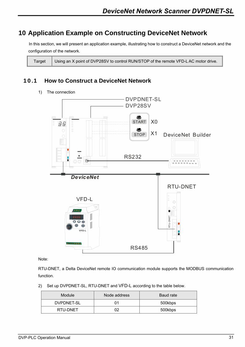
10 Application Example on Constructing DeviceNet Network In this section, we will present an application example, illustrating how to construct a DeviceNet network and the
configuration of the network.
Target Using an X point of DVP28SV to control RUN/STOP of the remote VFD-L AC motor drive.
10.1 How to Construct a DeviceNet Network
1) The connection
DeviceNetR
TU
-DN
ET
RTU-DNET
RS232
DeviceNet Builder
START
STOP
VFD-L
DVP28SVDVPDNET-SL
X0
X1
RS485
VFD-L
Note:
RTU-DNET, a Delta DeviceNet remote IO communication module supports the MODBUS communication
function.
2) Set up DVPDNET-SL, RTU-DNET and VFD-L according to the table below.
Module Node address Baud rate
DVPDNET-SL 01 500kbps
RTU-DNET 02 500kbps
DVP-PLC Operation Manual 31
DeviceNet Network Scanner DVPDNET-SL
VFD-L
parameter Set value Explanation
02-00 4 Transmit the frequency of VFD-L via RS485 communication.
02-01 3 Control operation of VFD-L via RS485 communication.
09-00 1 Set the node address of VFD-L in Modbus to 1. 09-01 1 Set the communication rate of VFD-L in Modbus 9600 09-04 1 Set the communication format of VFD-L in Modbus to
7, E, 1, ASCII.
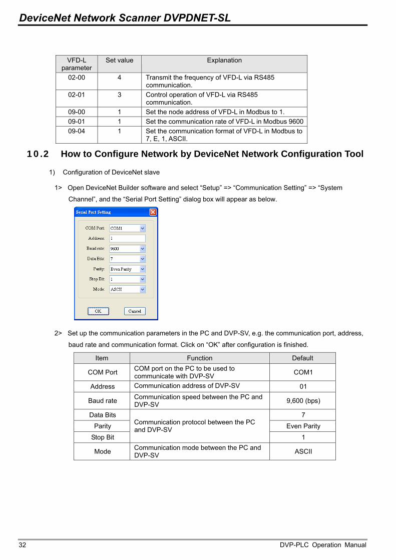
10.2 How to Configure Network by DeviceNet Network Configuration Tool
1) Configuration of DeviceNet slave
1> Open DeviceNet Builder software and select “Setup” => “Communication Setting” => “System
Channel”, and the “Serial Port Setting” dialog box will appear as below.
2> Set up the communication parameters in the PC and DVP-SV, e.g. the communication port, address,
baud rate and communication format. Click on “OK” after configuration is finished.
Item Function Default
COM Port COM port on the PC to be used to communicate with DVP-SV COM1
Address Communication address of DVP-SV 01
Baud rate Communication speed between the PC and DVP-SV 9,600 (bps)
Data Bits 7
Parity Even Parity
Stop Bit
Communication protocol between the PC and DVP-SV
1
Mode Communication mode between the PC and DVP-SV ASCII
DVP-PLC Operation Manual 32
DeviceNet Network Scanner DVPDNET-SL
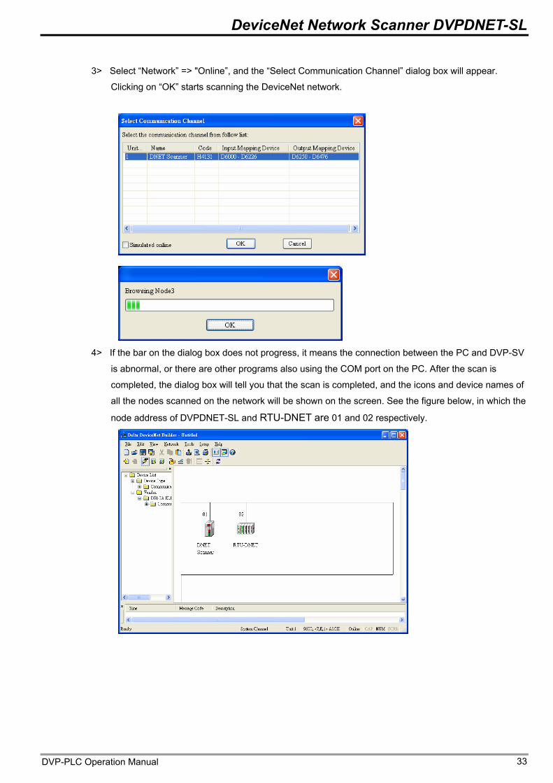
3> Select “Network” => "Online”, and the “Select Communication Channel” dialog box will appear.
Clicking on “OK” starts scanning the DeviceNet network.
4> If the bar on the dialog box does not progress, it means the connection between the PC and DVP-SV
is abnormal, or there are other programs also using the COM port on the PC. After the scan is
completed, the dialog box will tell you that the scan is completed, and the icons and device names of
all the nodes scanned on the network will be shown on the screen. See the figure below, in which the
node address of DVPDNET-SL and RTU-DNET are 01 and 02 respectively.
DVP-PLC Operation Manual 33
DeviceNet Network Scanner DVPDNET-SL
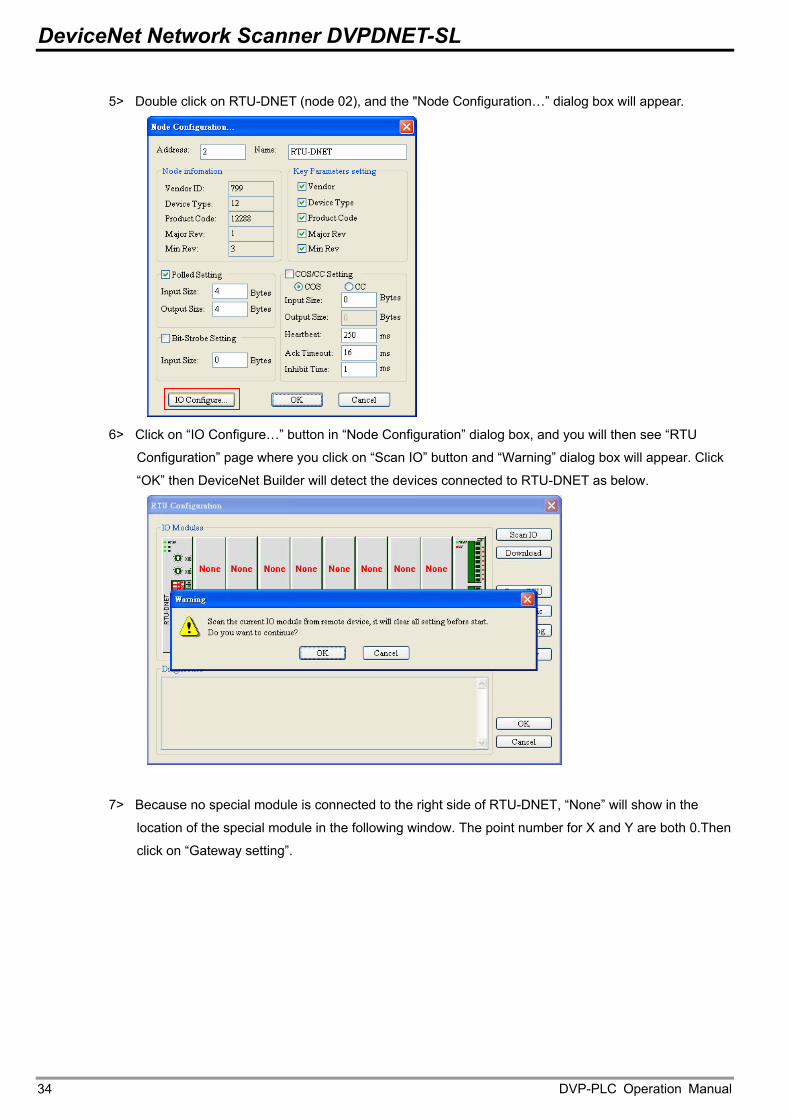
5> Double click on RTU-DNET (node 02), and the "Node Configuration…” dialog box will appear.
6> Click on “IO Configure…” button in “Node Configuration” dialog box, and you will then see “RTU
Configuration” page where you click on “Scan IO” button and “Warning” dialog box will appear. Click
“OK” then DeviceNet Builder will detect the devices connected to RTU-DNET as below.
7> Because no special module is connected to the right side of RTU-DNET, “None” will show in the
location of the special module in the following window. The point number for X and Y are both 0.Then
click on “Gateway setting”.
DVP-PLC Operation Manual 34
DeviceNet Network Scanner DVPDNET-SL
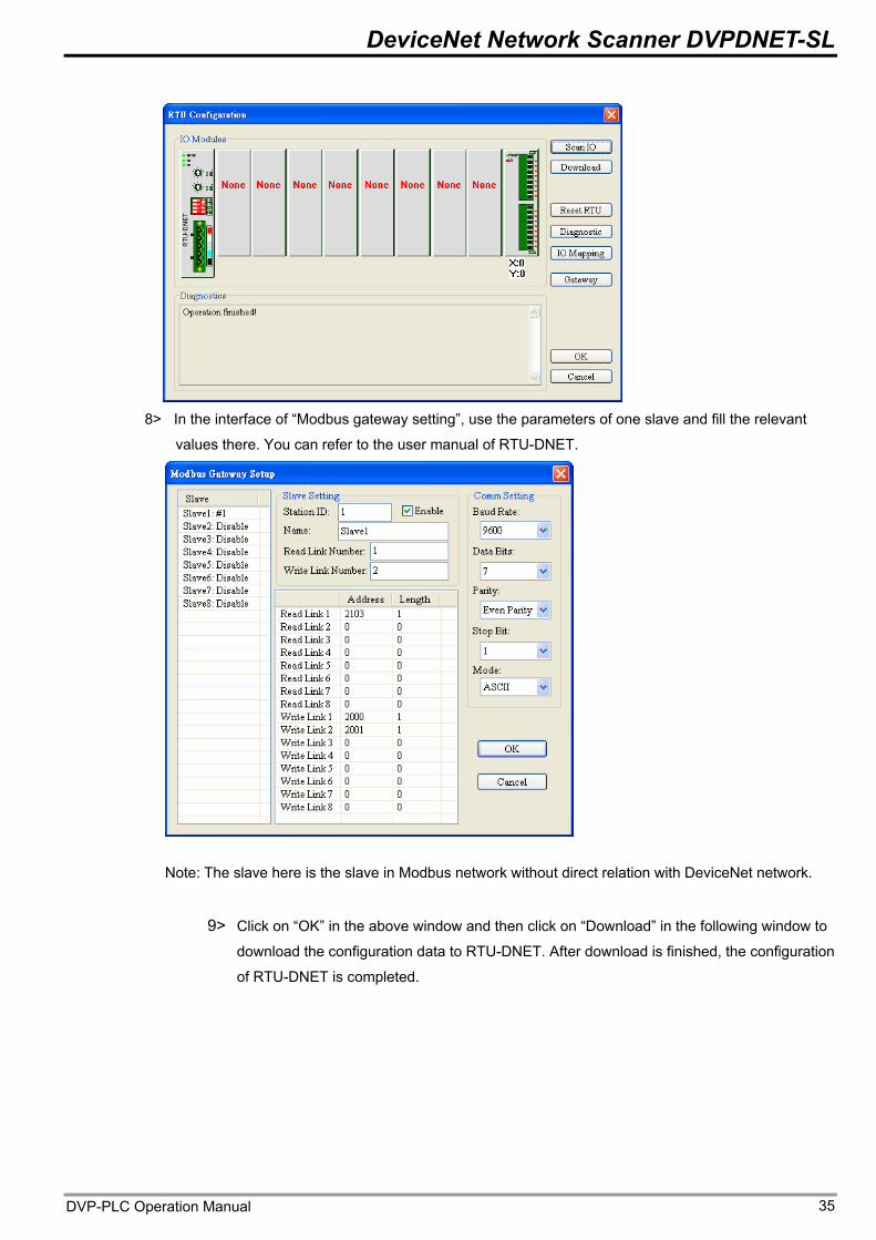
8> In the interface of “Modbus gateway setting”, use the parameters of one slave and fill the relevant
values there. You can refer to the user manual of RTU-DNET.
Note: The slave here is the slave in Modbus network without direct relation with DeviceNet network.
9> Click on “OK” in the above window and then click on “Download” in the following window to
download the configuration data to RTU-DNET. After download is finished, the configuration
of RTU-DNET is completed.
DVP-PLC Operation Manual 35
DeviceNet Network Scanner DVPDNET-SL
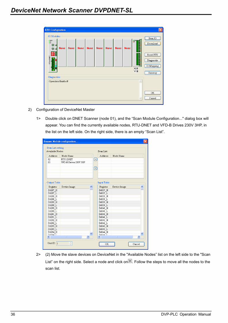
2) Configuration of DeviceNet Master
1> Double click on DNET Scanner (node 01), and the “Scan Module Configuration..." dialog box will
appear. You can find the currently available nodes, RTU-DNET and VFD-B Drives 230V 3HP, in
the list on the left side. On the right side, there is an empty “Scan List”.
2> (2) Move the slave devices on DeviceNet in the "Available Nodes” list on the left side to the "Scan
List” on the right side. Select a node and click on > . Follow the steps to move all the nodes to the
scan list.
DVP-PLC Operation Manual 36
DeviceNet Network Scanner DVPDNET-SL
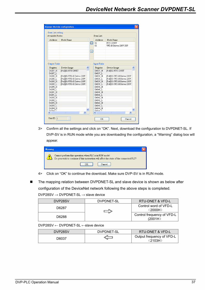
3> Confirm all the settings and click on “OK”. Next, download the configuration to DVPDNET-SL. If
DVP-SV is in RUN mode while you are downloading the configuration, a “Warning” dialog box will
appear.
4> Click on “OK” to continue the download. Make sure DVP-SV is in RUN mode.
The mapping relation between DVPDNET-SL and slave device is shown as below after
configuration of the DeviceNet network following the above steps is completed. DVP28SV → DVPDNET-SL → slave device
DVP28SV DVPDNET-SL RTU-DNET & VFD-L Control word of VFD-L
(2000H) D6287
D6288
Control frequency of VFD-L (2001H)
DVP28SV ← DVPDNET-SL ←slave device
DVP28SV DVPDNET-SL RTU-DNET & VFD-L Output frequency of VFD-L
(2103H) D6037
DVP-PLC Operation Manual 37
DeviceNet Network Scanner DVPDNET-SL
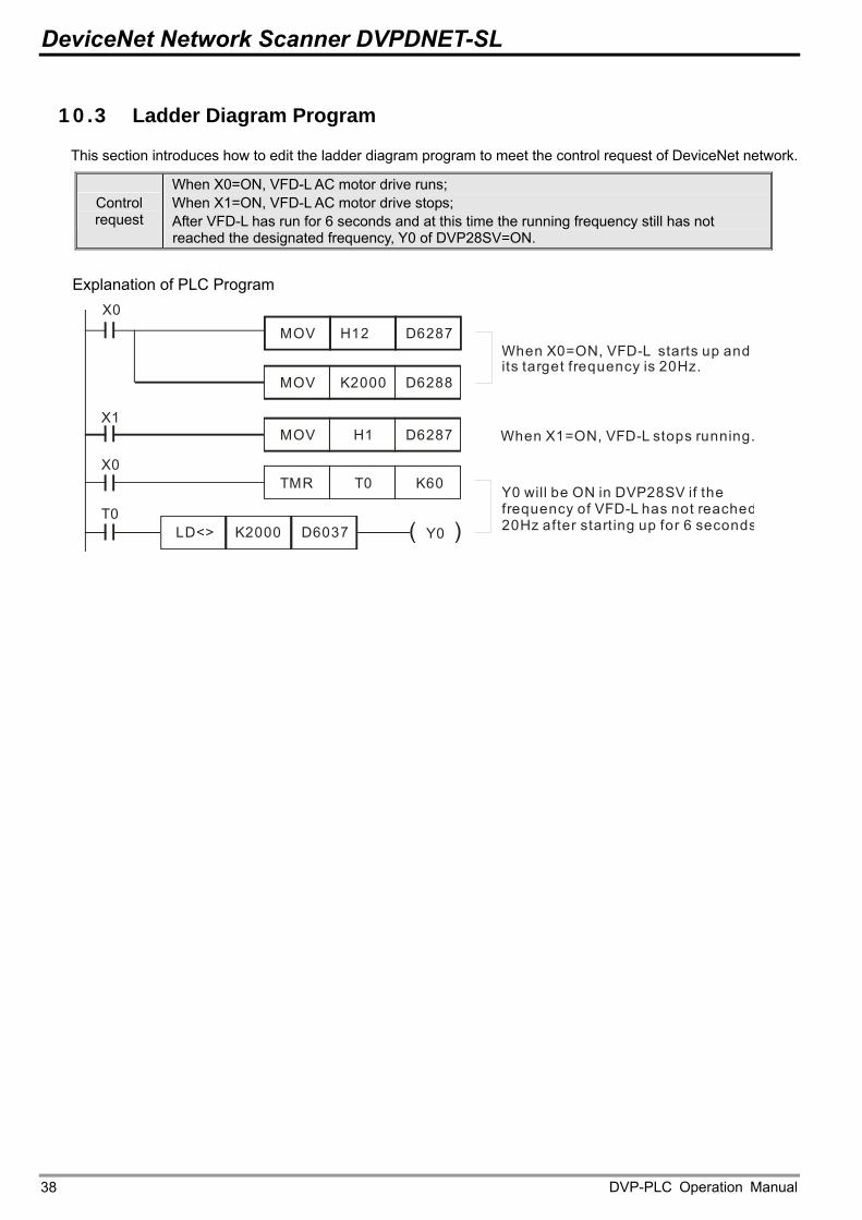
10.3 Ladder Diagram Program
This section introduces how to edit the ladder diagram program to meet the control request of DeviceNet network.
Control request
When X0=ON, VFD-L AC motor drive runs; When X1=ON, VFD-L AC motor drive stops; After VFD-L has run for 6 seconds and at this time the running frequency still has not reached the designated frequency, Y0 of DVP28SV=ON.
Explanation of PLC Program
MOV H1 D6287
X0
MOV K2000 D6288
X1
TMR T0 K60
LD<> K2000 D6037
MOV H12 D6287When X0=ON, VFD-L starts up and its target frequency is 20Hz.
When X1=ON, VFD-L stops running.
Y0 will be ON in DVP28SV if the frequency of VFD-L has not reached20Hz after starting up for 6 seconds
X0
T0Y0( )
DVP-PLC Operation Manual 38
DeviceNet Network Scanner DVPDNET-SL
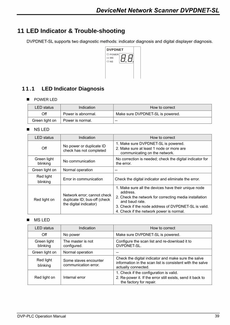
11 LED Indicator & Trouble-shooting DVPDNET-SL supports two diagnostic methods: indicator diagnosis and digital displayer diagnosis.
DVPDNETPOWERMS
NS
11.1 LED Indicator Diagnosis
POWER LED
LED status Indication How to correct
Off Power is abnormal. Make sure DVPDNET-SL is powered.
Green light on Power is normal. --
NS LED
LED status Indication How to correct
Off No power or duplicate ID check has not completed
1. Make sure DVPDNET-SL is powered. 2. Make sure at least 1 node or more are
communicating on the network. No correction is needed; check the digital indicator for the error.
Green light blinking No communication
Green light on Normal operation --
Red light blinking
Error in communication Check the digital indicator and eliminate the error.
Red light on Network error; cannot check duplicate ID; bus-off (check the digital indicator)
1. Make sure all the devices have their unique node address.
2. Check the network for correcting media installation and baud rate.
3. Check if the node address of DVPDNET-SL is valid.4. Check if the network power is normal.
MS LED
LED status Indication How to correct
Off No power Make sure DVPDNET-SL is powered.
Green light blinking
The master is not configured.
Configure the scan list and re-download it to DVPDNET-SL.
Green light on Normal operation -- Check the digital indicator and make sure the salve information in the scan list is consistent with the salve actually connected.
Red light blinking
Some slaves encounter communication error.
Red light on Internal error 1. Check if the configuration is valid. 2. Re-power it. If the error still exists, send it back to
the factory for repair.
DVP-PLC Operation Manual 39
DeviceNet Network Scanner DVPDNET-SL
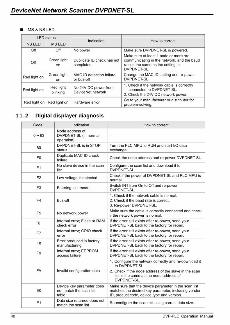
MS & NS LED
LED status
NS LED MS LED Indication How to correct
Off Off No power Make sure DVPDNET-SL is powered. Make sure at least 1 node or more are communicating in the network, and the baud rate is the same as the setting in DVPDNET-SL.
Off Green light on
Duplicate ID check has not completed.
Red light on Green light on
MAC ID detection failure or bus-off
Change the MAC ID setting and re-power DVPDNET-SL.
Red light on Red light blinking
No 24V DC power from DeviceNet network
1. Check if the network cable is correctly connected to DVPDNET-SL.
2. Check the 24V DC network power. Go to your manufacturer or distributor for problem-solving. Red light on Red light on Hardware error
11.2 Digital displayer diagnosis Code Indication How to correct
0 ~ 63 Node address of DVPDNET-SL (in normal operation)
--
80 DVPDNET-SL is in STOP status.
Turn the PLC MPU to RUN and start I/O data exchange.
F0 Duplicate MAC ID check failure Check the node address and re-power DVPDNET-SL.
F1 No slave device in the scan list.
Configure the scan list and download it to DVPDNET-SL. Check if the power of DVPDNET-SL and PLC MPU is normal. F2 Low voltage is detected.
Switch IN1 from On to Off and re-power DVPDNET-SL. F3 Entering test mode
F4 Bus-off 1. Check if the network cable is normal. 2. Check if the baud rate is correct. 3. Re-power DVPDNET-SL. Make sure the cable is correctly connected and check if the network power is normal. F5 No network power
F6 Internal error; Flash or RAM check error
If the error still exists after re-power, send your DVPDNET-SL back to the factory for repair.
F7 Internal error; GPIO check error
If the error still exists after re-power, send your DVPDNET-SL back to the factory for repair.
F8 Error produced in factory manufacturing
If the error still exists after re-power, send your DVPDNET-SL back to the factory for repair.
F9 Internal error; EEPROM access failure
If the error still exists after re-power, send your DVPDNET-SL back to the factory for repair.
FA Invalid configuration data
1. Configure the network correctly and re-download it to DVPDNET-SL.
2. Check if the node address of the slave in the scan list is the same as the node address of DVPDNET-SL.
E0 Device key parameter does not match the scan list table.
Make sure that the device parameter in the scan list matches the desired key parameter, including vendor ID, product code, device type and version.
E1 Data size returned does not match the scan list. Re-configure the scan list using correct data size.
DVP-PLC Operation Manual 40
DeviceNet Network Scanner DVPDNET-SL
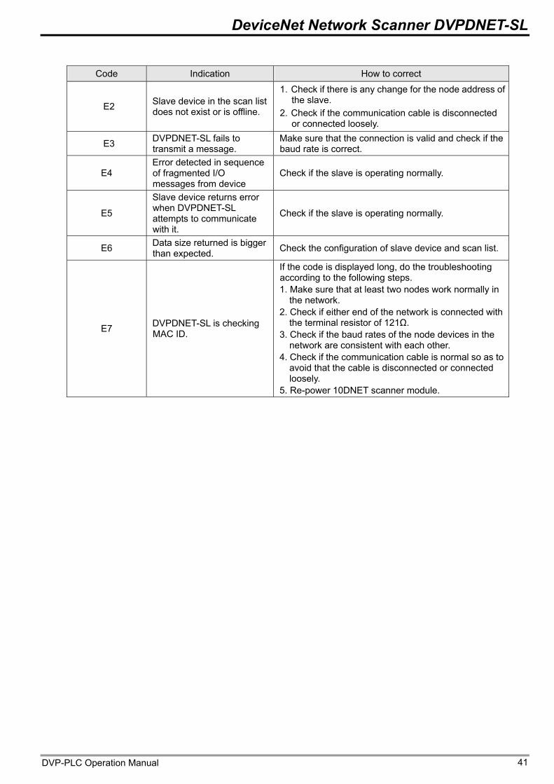
Code Indication How to correct
E2 Slave device in the scan list does not exist or is offline.
1. Check if there is any change for the node address of the slave.
2. Check if the communication cable is disconnected or connected loosely.
E3 DVPDNET-SL fails to transmit a message.
Make sure that the connection is valid and check if the baud rate is correct.
E4 Error detected in sequence of fragmented I/O messages from device
Check if the slave is operating normally.
E5
Slave device returns error when DVPDNET-SL attempts to communicate with it.
Check if the slave is operating normally.
E6 Data size returned is bigger than expected. Check the configuration of slave device and scan list.
E7 DVPDNET-SL is checking MAC ID.
If the code is displayed long, do the troubleshooting according to the following steps. 1. Make sure that at least two nodes work normally in
the network. 2. Check if either end of the network is connected with
the terminal resistor of 121Ω. 3. Check if the baud rates of the node devices in the
network are consistent with each other. 4. Check if the communication cable is normal so as to
avoid that the cable is disconnected or connected loosely.
5. Re-power 10DNET scanner module.
DVP-PLC Operation Manual 41