DVM S Control Training Manual for North America . . . Points of Refrigerant Control (Cooling...
83
DVM S Control Training Manual for North America - Sequence of Operations -
Transcript of DVM S Control Training Manual for North America . . . Points of Refrigerant Control (Cooling...
DVM S Control Training
Manual for North America
- Sequence of Operations -
1/#
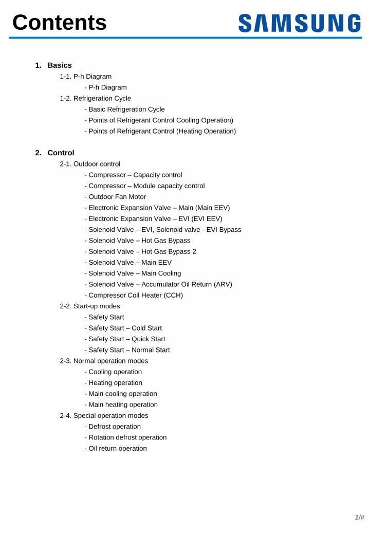
Contents
1. Basics
1-1. P-h Diagram
- P-h Diagram
1-2. Refrigeration Cycle
- Basic Refrigeration Cycle
- Points of Refrigerant Control Cooling Operation)
- Points of Refrigerant Control (Heating Operation)
2. Control
2-1. Outdoor control- Compressor – Capacity control
- Compressor – Module capacity control
- Outdoor Fan Motor
- Electronic Expansion Valve – Main (Main EEV)
- Electronic Expansion Valve – EVI (EVI EEV)
- Solenoid Valve – EVI, Solenoid valve - EVI Bypass
- Solenoid Valve – Hot Gas Bypass
- Solenoid Valve – Hot Gas Bypass 2
- Solenoid Valve – Main EEV
- Solenoid Valve – Main Cooling
- Solenoid Valve – Accumulator Oil Return (ARV)
- Compressor Coil Heater (CCH)
2-2. Start-up modes
- Safety Start
- Safety Start – Cold Start
- Safety Start – Quick Start
- Safety Start – Normal Start
2-3. Normal operation modes
- Cooling operation
- Heating operation
- Main cooling operation
- Main heating operation
2-4. Special operation modes
- Defrost operation
- Rotation defrost operation
- Oil return operation

2/#
.
.
.
.
Contents
2-5. Protective control
- High Pressure Protection
- Low Pressure Protection
- Compression Ratio Protection
- Discharge Temperature Protection
- DSH (Discharge Super Heat) protection
- IPM (Intelligent Power Module) temperature protection
- Maximum current limit (total)
- Maximum current limit (each compressor)
- Freezing prevention
2-6. Indoor unit control
- Operation Modes
- Auto mode
- Auto Change Over
- Thermo On/Off
- Temperature Compensation
- Fan control in thermo-Off condition
- Fan Speed Control
- Electronic Expansion Valve (EEV)
- Drain Pump Control
- Cold Air Prevention
3. Others
3-1. Field Setting
- Emergency operation for compressor malfunction
- Cooling capacity correction
- Heating capacity correction
- Current restriction rate
- Oil collection interval
- Temperature to trigger defrost operation
- Fan speed correction for outdoor unit
- Silent mode for night-time
- High-head condition setting
- Long-piping condition setting
- Energy control operation (ECO)
- Rotation defrost
- Expand operational temperature range for cooling
- Channel address
- Snow accumulation prevention control
- Speed operation
- Max capacity restriction
3/#
.
.
.
.
.
Liquid + Vapor
Superheated
Vapor
Subcooled
Liquid
Isothermal
Line
Vapor quality
Saturated
Vapor Line
Saturated
Liquid Line
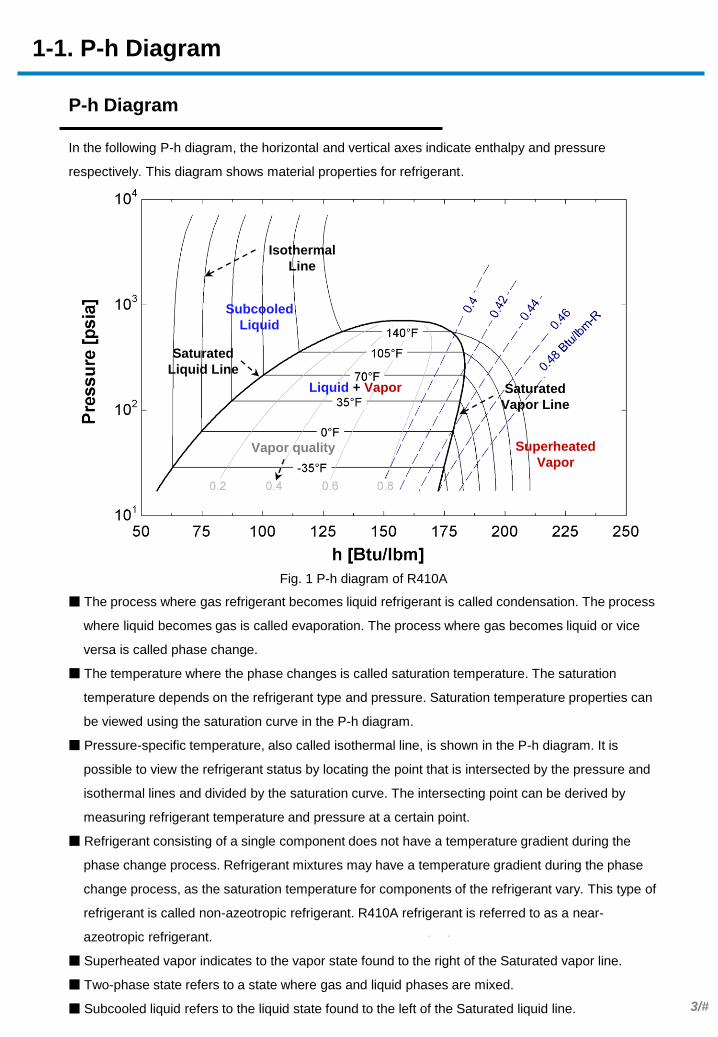
P-h Diagram
In the following P-h diagram, the horizontal and vertical axes indicate enthalpy and pressure
respectively. This diagram shows material properties for refrigerant.
Fig. 1 P-h diagram of R410A
■ The process where gas refrigerant becomes liquid refrigerant is called condensation. The process
where liquid becomes gas is called evaporation. The process where gas becomes liquid or vice
versa is called phase change.
■ The temperature where the phase changes is called saturation temperature. The saturation
temperature depends on the refrigerant type and pressure. Saturation temperature properties can
be viewed using the saturation curve in the P-h diagram.
■ Pressure-specific temperature, also called isothermal line, is shown in the P-h diagram. It is
possible to view the refrigerant status by locating the point that is intersected by the pressure and
isothermal lines and divided by the saturation curve. The intersecting point can be derived by
measuring refrigerant temperature and pressure at a certain point.
■ Refrigerant consisting of a single component does not have a temperature gradient during the
phase change process. Refrigerant mixtures may have a temperature gradient during the phase
change process, as the saturation temperature for components of the refrigerant vary. This type of
refrigerant is called non-azeotropic refrigerant. R410A refrigerant is referred to as a near-
azeotropic refrigerant.
■ Superheated vapor indicates to the vapor state found to the right of the Saturated vapor line.
■ Two-phase state refers to a state where gas and liquid phases are mixed.
■ Subcooled liquid refers to the liquid state found to the left of the Saturated liquid line.
1-1. P-h Diagram
4/#
.
..
Basic Refrigeration Cycle
The following figure shows the basic refrigeration cycle.
Fig. 2 Basic refrigerant cycle
Fig. 3 P-h diagram of refrigeration cycle
■ Difference between discharge temperature and high pressure saturation temperature is referred to
as discharge superheated degree.
■ Difference between suction temperature and low pressure saturation temperature is referred to as
suction superheated degree.
■ Difference between condenser exit temperature and high pressure saturation temperature is
referred to as subcooled degree.
Superheated degree must be calculated at the evaporator exit. This prevents wet compression.
Refrigerant flow from the evaporator must be adjusted using the expansion valve so that only
superheated vapor can flow into the compressor.
High Pressure Vapor High Pressure Liquid
Low Pressure Gas and Liquid Low Pressure Gas
Compressor Expansion valve
Condenser
Evaporator
Qe
Qc
Qc : Condensing capacity
Qe : Evaporating capacity
1-2. Refrigeration Cycle
Suction
Temperature
Discharge
Temperature
Discharge Superheated
Degree (DSH) Subcooled degree (SC)
Pc
Pe Cooling effect
Heating effect
Suction Superheat (SH)

5/#
. . .
Points of Refrigerant Control (Cooling Operation)
Cooling mode is affected by the quantity, capacity, and fan speed of active indoor units. Indoor air
temperature and humidity also affect the mode.
Fig. 4 Refrigerant control for cooling operation
■ Adjusting the compressor capacity
Adjust the compressor speed to match the evaporation pressure to the target pressure.
Evaporation pressure is measured by the low pressure sensor on the outdoor unit in order to
adjust the cooling capacity according to load.
■ Adjust the indoor unit EEV to sync the refrigerant superheated degree for the indoor heat
exchanger (formula: exit refrigerant temperature - entrance refrigerant temperature) with the
target superheated degree.
Compressor Expansion valve
(Fully opened)
Condenser
Evaporator
Qe
Qc
High Pressure Vapor High Pressure Liquid
Thermistor
Indoor
Outdoor
Lo
w P
res
su
re Liq
uid
L
ow
Pre
ss
ure
Ga
s
Superheated
degree control
Low Pressure Sensor
High Pressure Sensor
Suction Thermistor
1-2. Refrigeration Cycle
Qc : Condensing capacity
Qe : Evaporating capacity

6/#
.
.
.
.
.
Subcooled degree
control
High Pressure Sensor
Cooling mode is affected by the quantity, capacity, and fan speed of active indoor units. Indoor air
temperature and humidity also affect the mode.
Fig. 5 Refrigerant control for heating operation
■ Adjusting the compressor capacity
Adjust the compressor speed to match the condensing pressure to the target pressure.
Condensing pressure is measured by the high pressure sensor on the outdoor unit in order to
adjust the heating capacity according to load.
■ Adjust the outdoor unit EEV to sync the refrigerant superheated degree for the outdoor heat
exchanger (formula: compressor suction temperature - low pressure saturation temperature) with
the target superheated degree.
■ Adjust the indoor unit EEV to sync the refrigerant supercooling degree for the indoor heat
exchanger (formula: high pressure saturation temperature - entrance refrigerant temperature) with
the target supercooling degree.
Points of Refrigerant Control (Heating Operation)
Compressor Expansion valve
Evaporator
Condenser
Qe
Qc
High Pressure Vapor High Pressure Liquid
Thermistor
Outdoor
Indoor
Low Pressure Gas and Liquid Low Pressure Gas
Suction Thermistor
Low Pressure Sensor
1-2. Refrigeration Cycle
Qc : Condensing capacity
Qe : Evaporating capacity

7/#
Compressor – Capacity control
Purpose
Concept
In cooling case
- The capacity of a compressor is controlled by assuming the target pressure during cooling
operation. Measure pressure using the pressure sensor (low pressure sensor) installed in
the outdoor unit. In case that the measured value is lower than the target pressure, lower
the operating capacity of the compressor considering that the operating capacity is higher
compared to load. In case that the measured value is higher than the target pressure,
raise the operating capacity of the compressor considering that the operating capacity is
lower compared to load.
- The compressor frequency is adjusted through fuzzy control to enable cooling according
to the target low pressure.
- The compressor frequency is adjusted through fuzzy control to enable heating according
to the target high pressure.
Control specifications in detail
- Adjust the compressor operation frequency through fuzzy control. This adjusts the
capacity according to load in cooling or heating mode.
Low pressure < Target low pressure Target low pressure < Low pressure
Comp Hz down Comp Hz up
Excessive capacity Insufficient capacity
Capacity decreasing Capacity increasing
Target low pressure Hz Down
Hz UP
Hz Down
2-1. Outdoor control

8/#
. . - The target pressure value is as in the table and the initial setting value is 114psi,g. The
target pressure is adjusted considering the rise and fall of the pressure in the pipe. It is
calculated using evap in temperature representing the pressure of the indoor unit. In case
that rise and fall of the pressure within the pipe are big, the pressure cannot be maintained
in accordance with load due to high evaporated pressure of the indoor unit despite the
target pressure met. The level of rise and fall of the pressure within the pipe is recognized
considering the evaporated pressure using evap in. In case the temperature reaches the
setting temperature, maintain the target pressure judging from the evaporated pressure at
a certain point. In case that the evap in temperature is higher than the setting value, lower
the target pressure. Reversely, in case that the evap in temperature is lower than the
setting value, raise the target pressure. In case that the setting value of the evap in
temperature is required to be adjusted, it can be adjusted in the main PBA by referring to
the installation manual.
Target low pressure control
- avg. evap in temp. = setting target low p. maintain
- avg. evap in temp. < setting target low p. increase
- avg. evap in temp. > setting target low p. decrease
Target low pressure (psi,g)
85 92 100 107 114 121 128
- Default target : 114 psi,g
- Setting for target avg. evap in = ODU option setting
2-1. Outdoor control
Compressor – Capacity control
9/#
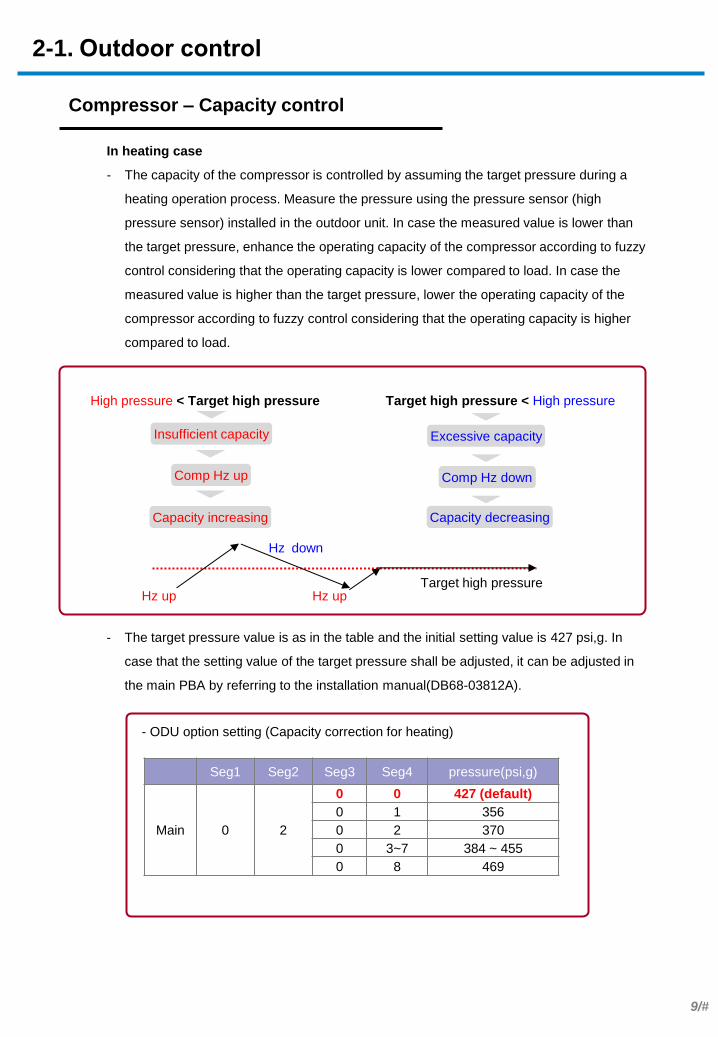
In heating case
- The capacity of the compressor is controlled by assuming the target pressure during a
heating operation process. Measure the pressure using the pressure sensor (high
pressure sensor) installed in the outdoor unit. In case the measured value is lower than
the target pressure, enhance the operating capacity of the compressor according to fuzzy
control considering that the operating capacity is lower compared to load. In case the
measured value is higher than the target pressure, lower the operating capacity of the
compressor according to fuzzy control considering that the operating capacity is higher
compared to load.
High pressure < Target high pressure Target high pressure < High pressure
Comp Hz up Comp Hz down
Insufficient capacity Excessive capacity
Capacity increasing Capacity decreasing
Target high pressure Hz up
Hz down
Hz up
- The target pressure value is as in the table and the initial setting value is 427 psi,g. In
case that the setting value of the target pressure shall be adjusted, it can be adjusted in
the main PBA by referring to the installation manual(DB68-03812A).
- ODU option setting (Capacity correction for heating)
Seg1 Seg2 Seg3 Seg4 pressure(psi,g)
Main 0 2
0 0 427 (default)
0 1 356
0 2 370
0 3~7 384 ~ 455
0 8 469
2-1. Outdoor control
Compressor – Capacity control
10/#
.
. .
.
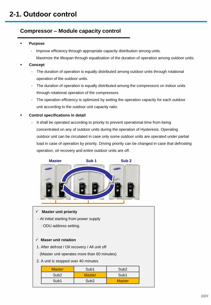
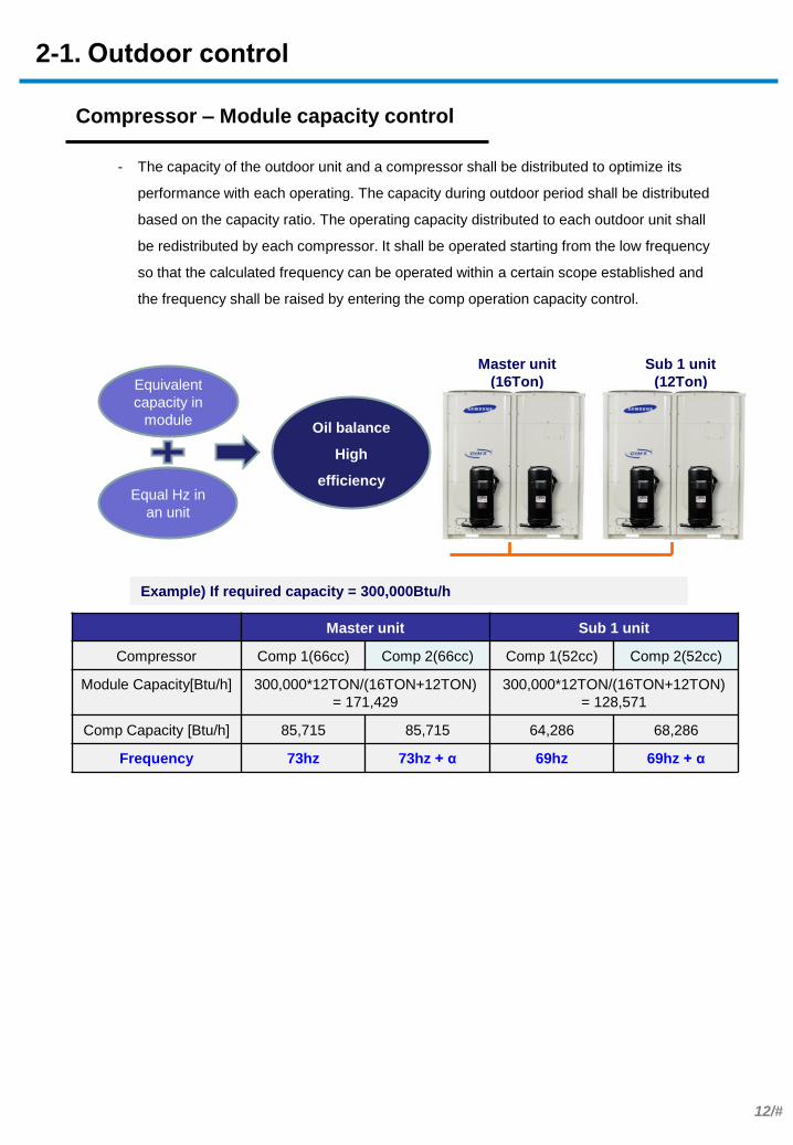
Compressor – Module capacity control
Purpose
Concept
- It shall be operated according to priority to prevent operational time from being
concentrated on any of outdoor units during the operation of Hysteresis. Operating
outdoor unit can be circulated in case only some outdoor units are operated under partial
load in case of operation by priority. Driving priority can be changed in case that defrosting
operation, oil recovery and entire outdoor units are off.
- Improve efficiency through appropriate capacity distribution among units.
Maximize the lifespan through equalization of the duration of operation among outdoor units.
- The duration of operation is equally distributed among outdoor units through rotational
operation of the outdoor units.
- The duration of operation is equally distributed among the compressors on indoor units
through rotational operation of the compressors.
- The operation efficiency is optimized by setting the operation capacity for each outdoor
unit according to the outdoor unit capacity ratio.
Master Sub 1 Sub 2
Master unit priority
- At initial starting from power supply
: ODU address setting.
Maser unit rotation
1. After defrost / Oil recovery / All unit off
(Master unit operates more than 60 minutes)
2. A unit is stopped over 40 minutes
Master Sub1 Sub2
Sub2 Master Sub1
Sub1 Sub2 Master
2-1. Outdoor control
Control specifications in detail

11/#
. . - Operation of a compressor shall be performed after adjusting priority to prevent operating
time from being concentrated on only certain compressor. Add the first priority to a
compressor with less operational time accumulated during the operation of an outdoor unit.
- Operate additional compressor in case the operating frequency are operated at more than
76Hz or at more than 60Hz for 3 minutes while the outdoor unit is operated only with one
compressor. It is designed that the efficiency of the compressor is operated in the most
ideal section.
INV1 INV2
Compressor priority in an unit
1. Which stopped longer
2. INV1 at initial starting from power supply
Additional compressor starting condition.
1. Over 60Hz & over 3mins operation
2. Over 76Hz operation
※ Efficiency of 30~80Hz is better than higher frequency
※ Each unit will decide individually
2-1. Outdoor control
Compressor – Module capacity control
12/#
. . - The capacity of the outdoor unit and a compressor shall be distributed to optimize its
performance with each operating. The capacity during outdoor period shall be distributed
based on the capacity ratio. The operating capacity distributed to each outdoor unit shall
be redistributed by each compressor. It shall be operated starting from the low frequency
so that the calculated frequency can be operated within a certain scope established and
the frequency shall be raised by entering the comp operation capacity control.
Equivalent
capacity in
module
Equal Hz in
an unit
Oil balance
High
efficiency
Master unit
(16Ton)
Sub 1 unit
(12Ton)
Example) If required capacity = 300,000Btu/h
Master unit Sub 1 unit
Compressor Comp 1(66cc) Comp 2(66cc) Comp 1(52cc) Comp 2(52cc)
Module Capacity[Btu/h] 300,000*12TON/(16TON+12TON)
= 171,429
300,000*12TON/(16TON+12TON)
= 128,571
Comp Capacity [Btu/h] 85,715 85,715 64,286 68,286
Frequency 73hz 73hz + α 69hz 69hz + α
2-1. Outdoor control
Compressor – Module capacity control
13/#
.
. .
.
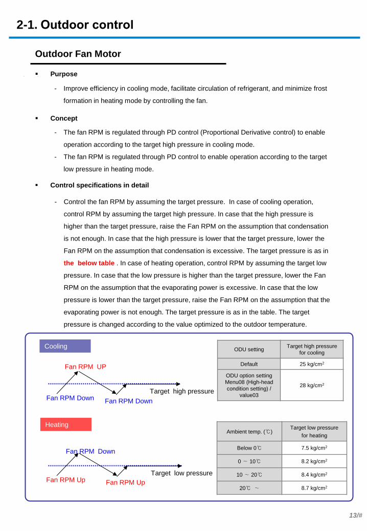
Outdoor Fan Motor
Purpose
Concept
- Control the fan RPM by assuming the target pressure. In case of cooling operation,
control RPM by assuming the target high pressure. In case that the high pressure is
higher than the target pressure, raise the Fan RPM on the assumption that condensation
is not enough. In case that the high pressure is lower that the target pressure, lower the
Fan RPM on the assumption that condensation is excessive. The target pressure is as in
the below table . In case of heating operation, control RPM by assuming the target low
pressure. In case that the low pressure is higher than the target pressure, lower the Fan
RPM on the assumption that the evaporating power is excessive. In case that the low
pressure is lower than the target pressure, raise the Fan RPM on the assumption that the
evaporating power is not enough. The target pressure is as in the table. The target
pressure is changed according to the value optimized to the outdoor temperature.
- The fan RPM is regulated through PD control (Proportional Derivative control) to enable
operation according to the target high pressure in cooling mode.
- The fan RPM is regulated through PD control to enable operation according to the target
low pressure in heating mode.
Control specifications in detail
- Improve efficiency in cooling mode, facilitate circulation of refrigerant, and minimize frost
formation in heating mode by controlling the fan.
Cooling
Target high pressure Fan RPM Down
Fan RPM UP
Fan RPM Down
Heating
Target low pressure Fan RPM Up
Fan RPM Down
Fan RPM Up
2-1. Outdoor control
ODU setting Target high pressure
for cooling
Default 25 kg/cm2
ODU option setting
Menu08 (High-head
condition setting) /
value03
28 kg/cm2
Ambient temp. (℃) Target low pressure
for heating
Below 0℃ 7.5 kg/cm2
0 ∼ 10℃ 8.2 kg/cm2
10 ∼ 20℃ 8.4 kg/cm2
20℃ ∼ 8.7 kg/cm2
14/#
. .
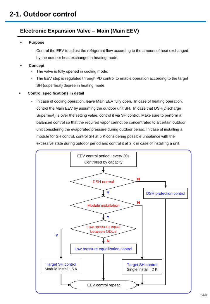
Electronic Expansion Valve – Main (Main EEV)
Purpose
Concept
- In case of cooling operation, leave Main EEV fully open. In case of heating operation,
control the Main EEV by assuming the outdoor unit SH. In case that DSH(Discharge
Superheat) is over the setting value, control it via SH control. Make sure to perform a
balanced control so that the required vapor cannot be concentrated to a certain outdoor
unit considering the evaporated pressure during outdoor period. In case of installing a
module for SH control, control SH at 5 K considering possible unbalance with the
excessive state during outdoor period and control it at 2 K in case of installing a unit.
- The valve is fully opened in cooling mode.
- The EEV step is regulated through PD control to enable operation according to the target
SH (superheat) degree in heating mode.
Control specifications in detail
- Control the EEV to adjust the refrigerant flow according to the amount of heat exchanged
by the outdoor heat exchanger in heating mode.
EEV control period : every 20s
Controlled by capacity
DSH normal
Module installation
Low pressure equal
between ODUs
Low pressure equalization control
Target SH control
Single install : 2 K
DSH protection control
EEV control repeat
Y
Y
Y
N
N
N
Target SH control
Module install : 5 K
2-1. Outdoor control
15/#
Electronic Expansion Valve – EVI (EVI EEV)
Purpose
Concept
- In case you need additional refrigerant flow in the compressor at a low temperature
heating, or if you can operate compressor effectively by increasing the flow rate through
the injection, it controls the EVI EEV in the EVI ON mode status.
- In addition, in case of cooling, it controls EVI EEV when needs super cooling in order to
deal with the installation conditions such as the long pipe installation or a high head.
- In EVI ON mode, optimizes the performance improvement through the injection by
controlling the SH as 2 K and 5 K to EVI EEV.
- When there is need of sub cooling in cooling mode, it controls the degree of sub cooling
as 20 K.
- The EVI EEV is regulated through PD control to secure the target subcooling degree in
cooling mode.
- The EVI EEV step is regulated through PD control to enable operation according to the
target EVI SH (superheat) degree in heating mode.
- The EVI EEV step is regulated to adjust the compressor discharge temperature (Td) to
obtain the target Td if additional performance is required in the low temperature section
while in heating mode.
Control specifications in detail
- Control the EVI EEV to secure a subcooling degree in cooling mode.
- Control the EVI EEV to optimize the performance in heating mode.
EVI mode Cooling Heating
EVI
Bypass
mode
▷ Sub-cooling control : 20 K
(High pressure Saturated temp. – Liquid
tube temp.)
▷ SH control
1. EVI Out – EVI In temp. > 10 K (priority)
2. Tdis = 194℉
▷SH (EVI out temp. – EVI in temp.)
control : 2 K
EVI On
mode
Remark ※ If comp discharge temp. is abnormally high, open EVI EEV to decrease the
discharge temperature
Sub-
cool 20 K
Upper EEV step
decrease
Below EEV Step
increase
SH 2 K
Upper EEV step
decrease
Below EEV Step
increase
2-1. Outdoor control
16/#
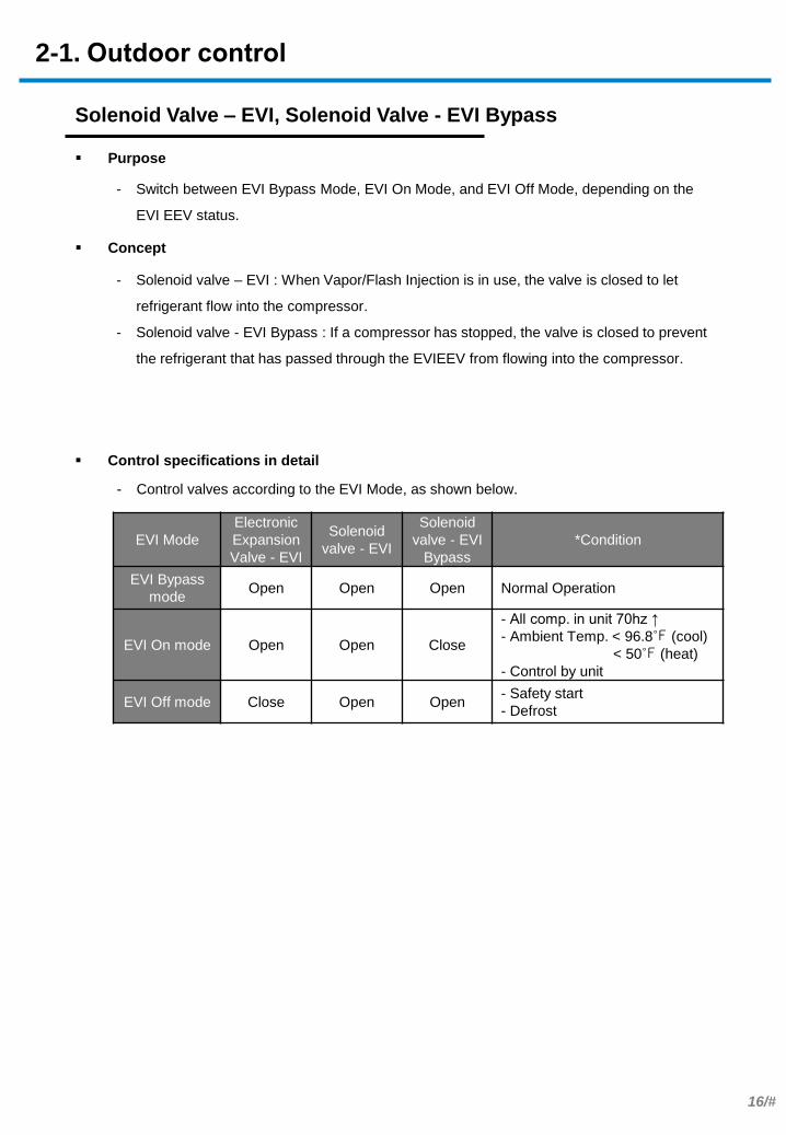
Solenoid Valve – EVI, Solenoid Valve - EVI Bypass
Purpose
Concept
- Control valves according to the EVI Mode, as shown below.
- Solenoid valve – EVI : When Vapor/Flash Injection is in use, the valve is closed to let
refrigerant flow into the compressor.
- Solenoid valve - EVI Bypass : If a compressor has stopped, the valve is closed to prevent
the refrigerant that has passed through the EVIEEV from flowing into the compressor.
Control specifications in detail
- Switch between EVI Bypass Mode, EVI On Mode, and EVI Off Mode, depending on the
EVI EEV status.
2-1. Outdoor control
EVI Mode
Electronic
Expansion
Valve - EVI
Solenoid
valve - EVI
Solenoid
valve - EVI
Bypass
*Condition
EVI Bypass
mode Open Open Open Normal Operation
EVI On mode Open Open Close
- All comp. in unit 70hz ↑
- Ambient Temp. < 96.8℉ (cool)
< 50℉ (heat)
- Control by unit
EVI Off mode Close Open Open - Safety start
- Defrost

17/#
Solenoid Valve - Hot Gas Bypass
Purpose
Concept
- ON if high pressure is above 561.8psi,g / OFF if below 547.6psi,g
- ON if cooling low pressure is below 45.5psi,g / OFF if above 59.7psi,g (at minimum
frequency, OFF if above 85.3psi,g)
- ON if cooling low pressure is below 12.8psi,g / OFF if above 24.2psi,g
- If either pressure is abnormal, the valve is opened to bypass the high-pressure gas to the
low pressure pipe. This will change the pressure.
Control specifications in detail
- Protect the system when high pressure is abnormally high or low pressure is abnormally
low.
2-1. Outdoor control
18/#
Solenoid Valve - Hot Gas Bypass 2
Purpose
Concept
- If using the Heat Recovery device, the valve is opened (ON) after cooling-only mode has
been on for more than 20 minutes or when cooling oil return mode is active.
- In cooling-only mode, the valve is opened to switch the high pressure gas pipe to the low
pressure gas pipe.
- If the valve is closed, refrigerant stagnates in the high pressure gas pipe causing a lack of
refrigerant.
- HR Only
Control specifications in detail
- Prevent refrigerant from stagnating in the high pressure gas pipe in cooling-only mode.
2-1. Outdoor control

19/#
Solenoid Valve – Main EEV
Purpose
Concept
- In main cooling mode, the valve is Off (closed)
- In main cooling mode, the valve is closed to prevent refrigerant from flowing using Check
Valve – EEV Bypass and enable the Main EEV to control the amount of refrigerant flowing
into the cooling indoor units.
- If the valve is opened, most refrigerant is bypassed via the valve which flows into the
cooling indoor units. As a result, there is insufficient refrigerant in active indoor units that
are under heating mode.
- HR Only
Control specifications in detail
- In main cooling mode, enable the Main EEV to control the amount of refrigerant flowing in
the cooling indoor units.
2-1. Outdoor control
20/#
Solenoid Valve – Main Cooling
Purpose
Concept
- In main cooling mode, the valve is On (opened)
- In main cooling mode, the valve is opened to send the high pressure to heating indoor
units and enable heating.
- HR Only
Control specifications in detail
- In main cooling mode, enable operation of heating indoor units.
2-1. Outdoor control

21/#
Solenoid Valve - Accumulator Oil Return (ARV)
Purpose
Concept
- Condition(s) required to close (Off) the valve : [ A or B or C ]
A. The system has stopped
B. DSH is higher than 10 K during start-up
C. The valve is closed for 2 minutes if DSH is higher than 10 K in air conditioning
mode
- Condition(s) required to open (On) the valve : None of the conditions required to close the
valve are satisfied
- During compressor operation, the valve is opened to return oil stagnating in the
accumulator.
- The valve is closed to protect the compressor in start-up mode or in a section where there
is concern about the potential for liquid compression due to low DSH.
Control specifications in detail
- Return oil stagnating in the accumulator.
2-1. Outdoor control
22/#
Compressor Coil Heater (CCH)
Purpose
Concept
- It is turned On if A or B is satisfied
A. The highest temperature of the compressor has remained below 122℉ for 2 min
B. The CCH has been Off for longer than 6 hours
- Condition(s) required to turn Off the CCH: [ A or B ]
A. The highest temperature of the compressor has remained above 131℉ for 30 min
B. The CCH has been On for longer than 6 hours
- If the internal temperature of an inactive compressor is abnormally low, the internal
temperature is increased through the CCH to evaporate the liquid refrigerant that has
flowed into the compressor. This will prevent liquid compression and poor lubrication.
Control specifications in detail
- Prevent compressor failure due to liquid compression or poor lubrication during
compressor start-up.
2-1. Outdoor control

23/#
. . .
- A start-up pattern is decided taking into account the compressor temperature, indoor and
outdoor temperatures, and operation ratio during start-up.
- Cold Start : If the compressor temperature is low, a low start-up frequency is used to
protect the compressor from liquid compression as well as poor lubrication due to oil foaming.
- Warm Start : If the compressor temperature is high, a standard start-up frequency is used
as there is no risk of liquid compression.
- Quick Start : If the operation ratio is high, compressors start at the same time to quickly
improve the performance.
- Normal Start : Compressors start one after another to enable safe operation if the operation
ratio of indoor units is low and the indoor or outdoor temperature is high or low.
- Cold Operation : If DSH is low, the frequency increase speed is decreased to protect the
compressors from liquid compression.
Safety Start
Purpose
Concept
- Protect the system and compressors by preventing poor lubrication due to liquid
compression or oil foaming.
- Enable high-speed cooling and heating through fast start-up if there is no risk of liquid
compression.
2-2. Start-up modes
Starting
Warm Start?
Quick Start Normal Start Cold Start
DSH* > 10 K
Normal Operation
Yes
Yes
Yes
No
No (if the compressor temp is low)
■ Compressor
protective start-up
■ Cold Operation
included
■ Stable start-up■ High-speed start-up
■ Prevention of liquid
compression
No (if the indoor unit operation ratio is low, or
the indoor/outdoor temperature is abnormally low or high) Quick Start?
Cold Operation
- DSH : Discharge superheat = Compressor discharge temperature* – High pressure saturation temperature
- Discharge temperature from DSH = Min { Max(Tdis*_comp1, Ttop*_comp1), Max(Tdis_comp2, Ttop_comp2) }
- Tdis : Temperature of discharge pipe
- Ttop : Temperature of compressor top
24/#
. .
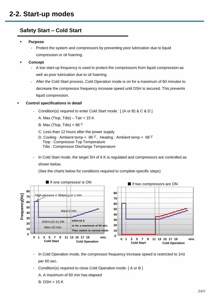
Safety Start – Cold Start
Purpose
Concept
- Protect the system and compressors by preventing poor lubrication due to liquid
compression or oil foaming.
- A low start-up frequency is used to protect the compressors from liquid compression as
well as poor lubrication due to oil foaming.
- After the Cold Start process, Cold Operation mode is on for a maximum of 60 minutes to
decrease the compressor frequency increase speed until DSH is secured. This prevents
liquid compression.
Control specifications in detail
- Condition(s) required to enter Cold Start mode : [ (A or B) & C & D ]
A. Max (Ttop, Tdis) – Tair < 15 K
B. Max (Ttop, Tdis) < 86℉
C. Less than 12 hours after the power supply
D. Cooling : Ambient temp < 86℉, Heating : Ambient temp < 68℉
Ttop : Compressor Top Temperature
Tdis : Compressor Discharge Temperature
- In Cold Start mode, the target SH of 6 K is regulated and compressors are controlled as
shown below.
(See the charts below for conditions required to complete specific steps)
- In Cold Operation mode, the compressor frequency increase speed is restricted to 1Hz
per 60 sec.
- Condition(s) required to close Cold Operation mode: [ A or B ]
A. A maximum of 60 min has elapsed
B. DSH > 15 K
Cold Start Cold Operation
■ If one compressor is ON
0 1 3 5 7 9 11 13 15 17 19 min.
Fre
qu
en
cy[H
z]
0
10
20
30
40
50
60
70
80
Max=2 min.
High pressure ≥ 384psi,g or 1 min
DSH>15 K
or for a maximum of 60 min.
Then switch to normal mode
DSH>(10 K) OR
Max=10 min.
Cold Start Cold Operation
■ If two compressors are ON
0 1 3 5 7 9 11 13 15 17 19 min. 0
10
20
30
40
50
60
70
80
2-2. Start-up modes

25/#
. .
Safety Start – Quick Start
Purpose
Concept
- Enable high-speed cooling and heating through quick start-up
- Compressors start at the same time to quickly improve the performance.
Control specifications in detail
- Condition(s) required to enter Quick Start mode: [ A & B ]
A. Required capacity is 30% or higher
B. Indoor and outdoor temperatures satisfy the Quick Start range shown below.
- In Quick Start mode, compressors are controlled as shown below. (See the chart below
for conditions required to complete specific steps)
- Condition(s) required to enter Normal Operation mode : [ A or B ]
A. DSH > 10 K B. Max (Tdis, Ttop) ≥ 86℉
- Cold Operation mode will activate if none of the conditions required to enter Normal
Operation mode are satisfied.
- In Cold Operation mode, the compressor frequency increase speed is restricted to 1Hz
per 30 sec.
- Condition(s) required to close Cold Operation mode : [ A or B ]
A. A maximum of 30 min has elapsed B. DSH > 15 K
Room
tem
pera
ture
(℉
)
Ambient temperature (℉)
Room
tem
pera
ture
(℉
)
Ambient temperature (℉)
Fre
qu
en
cy
0
10
20
30
40
50
60
70
80
Quick Start
0 1 3 5 7 9 11 13
High pressure>=384psi,g or 1 min
Normal / Cold Operation
15 17 19 min.
DSH>15 K
or High pressure: 398.3psi ,g↑
or Pressure ratio: 6.0 ↑
or Max=3 min.
Max = 60Hz, Min = 40Hz
Max=2 min.
Max=40Hz or start-up capacity
Normal Operation
Cold Operation
2-2. Start-up modes
Cooling
Quick start
Heating
Quick start

26/#
Safety Start – Normal Start
Purpose
Concept
- Stable start-up in a low-temperature section with overload
- Compressors start in sequential order to ensure stable operation if the indoor unit
operation ratio is low or there is an overload.
Control specifications in detail
- Condition(s) required to enter Normal Start mode : None of the conditions required to
enter Quick Start mode are satisfied
- In Normal Start mode, compressors are controlled as shown below. (See the chart below
for conditions required to complete specific steps)
- Condition(s) required to enter Normal Operation mode : [ A or B ]
A. DSH > 10 K B. Max (Tdis, Ttop) ≥ 86℉
- Cold Operation mode will activate if none of the conditions required to enter Normal
Operation mode are satisfied.
- In Cold Operation mode, the compressor frequency increase speed is restricted to 1Hz
per 30 sec.
- Condition(s) required to close Cold Operation mode: [ A or B ]
A. A maximum of 30 min has elapsed B. DSH > 15 K
Fre
qu
en
cy[H
z]
0
10
20
30
40
50
60
70
80
Pump Start Soft Start Mild Start
0 1 3 5 7 9 11 13
High pressure >=384psi,g or 1 min
Normal/Cold Operation
15 17 19 min.
Max = 60Hz, Min = 40Hz
Max=2 min.
Max=40Hz OR start-up capacity
Normal Operation
Cold Operation
DSH>15 K
or High pressure: 398.3psi,g↑
or Pressure ratio: 6.0 ↑
or Max=3 min.
2-2. Start-up modes

27/#
. . . .
Cooling operation
2-3. Normal operation modes
Purpose - Enable cooling in the entire target space.
Refrigerant Flow- Heat pump
Actuator Abbrev. - Normal Cooling
Compressor COMP Operation Target low pressure control (default: 113.8psi,g)
Range 14~140Hz
Outdoor Fan Motor OFM Operation Target high pressure control (default: 355.6psi,g)
Range 0-39step (0-1300rpm)
Electronic Expansion Valve – Main (Main EEV) E_M Operation Full Open
Range 2000step
Electronic Expansion Valve – EVI (EVI EEV) E_EVI Operation *Subcooling control (default: SC=20 K)
Range 0-480step
Solenoid Valve - 4way V_4W Operation Off
Solenoid Valve – EVI Bypass V_EB Operation On (Open): *T_a > 100.4℉ or 50Hz↓
Off (Close): T_a < 96.8℉↓ and 70Hz↑
Solenoid Valve – EVI V_EVI Operation On (Open)
Solenoid Valve – Hot Gas Bypass V_HG Operation Off (Close)
Solenoid Valve – Accumulator Oil Return V_AR Operation On (Open)
Solenoid Valve – Hot Gas Bypass 2 (HR Only) V_HG2 Operation On (Open)
Solenoid Valve – Main EEV (HR Only) V_ME Operation On (Open)
Solenoid Valve – Main Cooling (HR Only) V_MC Operation Off (Close)
Control specifications in detail

28/#
. .
Cooling operation
- Heat Recovery
2-3. Normal operation modes

29/#
. .
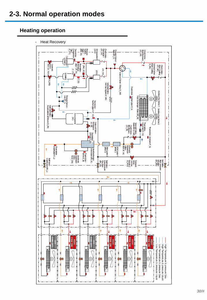
Heating operation
Purpose - Enable heating in the entire target space.
Refrigerant Flow
- Heatpump
Actuator Abbrev. - Target high pressure control (default : 426.7psi,g)
Compressor COMP Operation Target low pressure control (default: 106.7-123.7psi,g)
Range 20-160Hz
Outdoor Fan Motor OFM Operation *Superheat control (default: SH 2 K)
Range 0-39step (0-1300rpm)
Electronic Expansion Valve – Main (Main EEV) E_M Operation *EVI Superheat control (default : SH 2 K)
Range 125-2000step
Electronic Expansion Valve – EVI (EVI EEV) E_EVI Operation On
Range 0-480step
Solenoid Valve - 4way V_4W Operation On (Open): T_a > 59℉ or 50Hz↓
Off (Close): T_a < 50℉ and 70Hz↑
Solenoid Valve – EVI Bypass V_EB Operation On (Open)
Solenoid Valve – EVI V_EVI Operation Off (Close)
Solenoid Valve – Hot Gas Bypass V_HG Operation On (Open)
Solenoid Valve – Accumulator Oil Return V_AR Operation Off (Close)
Solenoid Valve – Hot Gas Bypass 2 (HR Only) V_HG2 Operation Off (Close)
Solenoid Valve – Main EEV (HR Only) V_ME Operation Off (Close)
Solenoid Valve – Main Cooling (HR Only) V_MC Operation Off (Close)
Control specifications in detail
2-3. Normal operation modes
30/#
. .
Heating operation
- Heat Recovery
2-3. Normal operation modes

31/#
Main cooling operation
Purpose
- Switch to heating mode on some indoor units while using cooling mode
Control specifications in detail
Actuator - Main Cooling
Compressor COMP Operation
Target low pressure control
(default: 113.8psi,g)
Range 14~140Hz
Outdoor Fan Motor OFM Operation
Target high pressure control
(default: 355.6psi,g)
Range 0-39step (0-1300rpm)
Electronic Expansion Valve – Main (Main EEV) E_M Operation
Cooling & Heating
capacity balance control
Range 300-2000step
Electronic Expansion Valve – EVI (EVI EEV) E_EVI Operation
*Subcooling control
(default: SC 20 K)
Range 0-480step
Solenoid Valve - 4way V_4W Operation Off
Solenoid Valve – EVI Bypass V_EB Operation
On (Open):
*T_a > 100.4℉ or 50Hz↓
Off (Close):
T_a < 96.8℉↓ and 70Hz↑
Solenoid Valve – EVI V_EVI Operation On (Open)
Solenoid Valve – Hot Gas Bypass V_HG Operation Off (Close)
Solenoid Valve – Accumulator Oil Return V_AR Operation On (Open)
Solenoid Valve – Hot Gas Bypass 2 (HR Only) V_HG2 Operation Off (Close)
Solenoid Valve – Main EEV (HR Only) V_ME Operation Off (Close)
Solenoid Valve – Main Cooling (HR Only) V_MC Operation On (Open)
2-3. Normal operation modes

32/#
. .
Main cooling operation
Refrigerant Flow
2-3. Normal operation modes

33/#
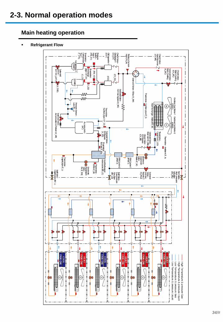
Main heating operation
Purpose
- Switch to cooling mode on some indoor units while using heating mode.
Control specifications in detail
Actuator - Main Heating
Compressor COMP Operation
Target high pressure control
(default: 426.7psi,g)
Range 20-160Hz
Outdoor Fan Motor OFM Operation
Target low pressure control
(default: 106.7-123.7psi,g)
Range 0-39step (0-1300rpm)
Electronic Expansion Valve – Main (Main EEV) E_M Operation
*Superheat control
(default: SH 2 K)
Range 125-2000step
Electronic Expansion Valve – EVI (EVI EEV) E_EVI Operation
*EVI Superheat control
(default: SH 2 K)
Range 0-480step
Solenoid Valve - 4way V_4W Operation On
Solenoid Valve – EVI Bypass V_EB Operation
On (Open):
T_a > 59℉ or 50Hz↓
Off (Close):
T_a < 50℉ and 70Hz↑
Solenoid Valve – EVI V_EVI Operation On (Open)
Solenoid Valve – Hot Gas Bypass V_HG Operation Off (Close)
Solenoid Valve – Accumulator Oil Return V_AR Operation On (Open)
Solenoid Valve – Hot Gas Bypass 2 (HR Only) V_HG2 Operation Off (Close)
Solenoid Valve – Main EEV (HR Only) V_ME Operation Off (Close)
Solenoid Valve – Main Cooling (HR Only) V_MC Operation Off (Close)
2-3. Normal operation modes
34/#
. .
Main heating operation
Refrigerant Flow
2-3. Normal operation modes

35/#
Defrost operation
Purpose
Concept
- Criteria used to decide whether to use defrost mode include the heat exchanger
temperature (Cond out, Suction) and the heating duration.
- Checking the heat exchanger temperature starts 30 minutes after Safety Start mode turns
off. Defrost mode starts if the Cond out or Suction temperature of each outdoor unit is
23℉ or lower and there is a sufficient degree of difference between the outdoor
temperature and the Cond out or Suction temperature.
- Checking the duration starts after Safety Start mode turns off. Defrost mode starts if the
outdoor temperature is 32℉ or higher and heating mode has been on for 2 hours under
the following condition: the Cond out temperature is lower than 35.6℉ and the low
pressure is 88.2psi or lower. Defrost mode can also start if the outdoor temperature is
below 23℉ and heating mode has been on for 2 hours under the following condition: the
low pressure is 88.2psi or lower and there is a sufficient difference between the outdoor
temperature and heat exchanger temperature.
- The learning-based defrost feature learns the electric current in the fan when there is no
frost formation in 3-cycle heating mode. The feature extends subsequent defrost mode,
started based on the heating duration, up to 18 hours if the electric current in the fan does
not rise by 8% or more compared to the frost-free state .
- Condition(s) required to turn off defrost mode: Cond out temp ≥ 53.6℉ OR 15 min after
defrost mode has started.
- Heat exchangers are checked for frost formation based on the heat exchanger
temperature (Cond out, Suction) and the heating duration.
- Cooling mode is on until the heat exchanger temperature (Cond out, Suction) reaches a
specific level.
- If the heating duration indicates that defrost mode should start, the heat exchangers are
checked for frost formation based on the electric current rise of the outdoor fans and then
heating mode is on for a maximum of 18 hours (learning-based defrost)
Control specifications in detail
- Optimize the heating performance by removing frost from the outdoor heat exchangers in
heating mode.
2-4. Special operation modes
36/#
. .
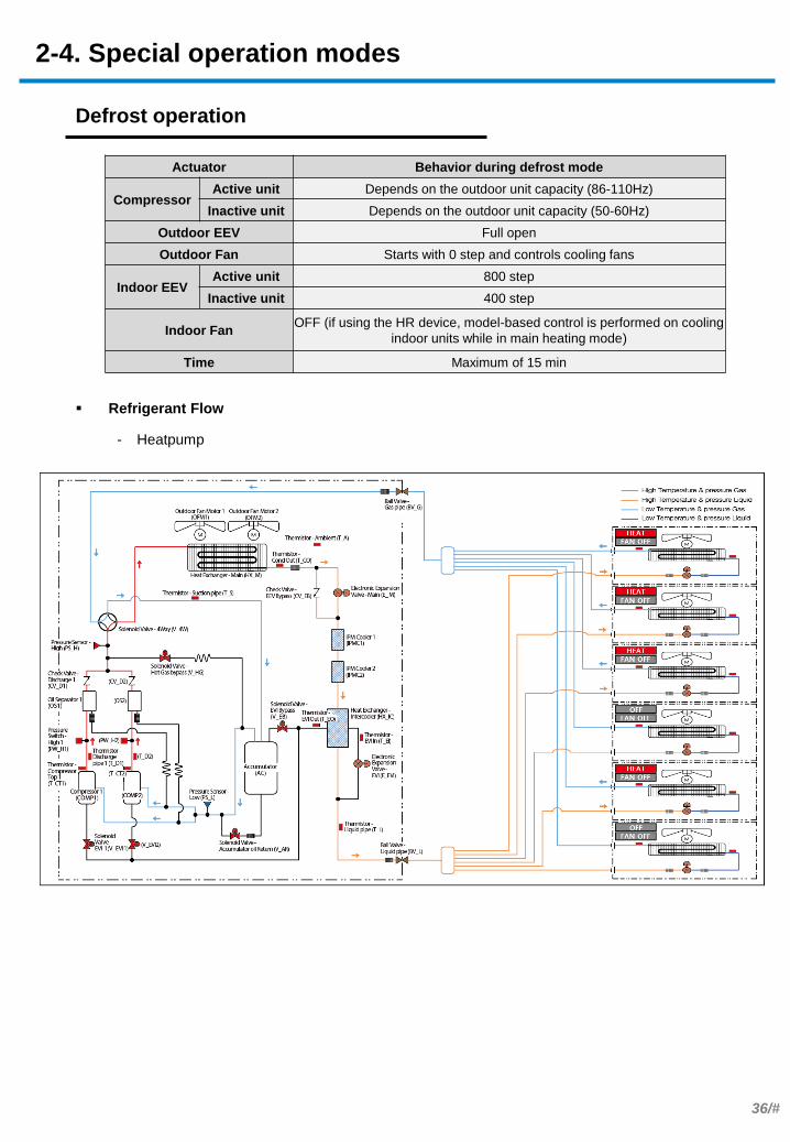
Refrigerant Flow
- Heatpump
Actuator Behavior during defrost mode
Compressor Active unit Depends on the outdoor unit capacity (86-110Hz)
Inactive unit Depends on the outdoor unit capacity (50-60Hz)
Outdoor EEV Full open
Outdoor Fan Starts with 0 step and controls cooling fans
Indoor EEV Active unit 800 step
Inactive unit 400 step
Indoor Fan OFF (if using the HR device, model-based control is performed on cooling
indoor units while in main heating mode)
Time Maximum of 15 min
Defrost operation
2-4. Special operation modes

37/#
. .
Defrost operation
- Heat Recovery
2-4. Special operation modes

38/#
Rotation defrost operation
Purpose
Concept
- Enabled only when rotational defrost mode has been enabled by the Key option.
- Rotational defrost operation is performed in the following cases: two or more outdoor units
are installed, the outdoor temperature is 23℉ or higher, rotational defrost has not been
performed 3 times consecutively, the previous defrost mode was a general defrost, or the
duration of rotational defrost < the quantity of indoor units x 10 min.
- For the sequence of rotational defrost, the order of priority for outdoor units is followed.
- For the temperature and time conditions required to enter defrost mode, the same
conditions as general defrost mode are applied.
- Condition(s) required to turn off defrost mode: Cond out temp ≥ 59℉ OR 12 min after
defrost mode has started.
- Defrost operation is performed on outdoor units in sequential order when main heating
mode is active on HR outdoor units.
- If rotational defrost mode is used 3 times consecutively, defrost operation will be
performed on all the outdoor units when defrost mode is turned on again.
Control specifications in detail
- Activate defrost mode on module-installed HR outdoor units in sequential order to improve
heating efficiency.
Actuator Outdoor units in defrost
mode
Units not being in defrost
mode
Compressor
Depends on the outdoor unit
capacity
(86-110Hz)
General control
Outdoor EEV Full close General control
Outdoor Fan 0 step General control
HR EEV Off General control
Main cooling
valve ON General control
Indoor EEV
Cooling indoor
unit
Active unit General control
Inactive unit Required step for control of the superheat degree
Heating
Indoor unit
Active unit General control
Inactive unit General control on inactive units
Indoor Fan
Cooling indoor
unit
Active unit General control
Inactive unit Set fan speed
Heating
Indoor unit
Active unit Mid fan speed
Inactive unit Off
Time Maximum of 12 min -
2-4. Special operation modes

39/#
. .
Rotation defrost operation
Refrigerant Flow
2-4. Special operation modes

40/#
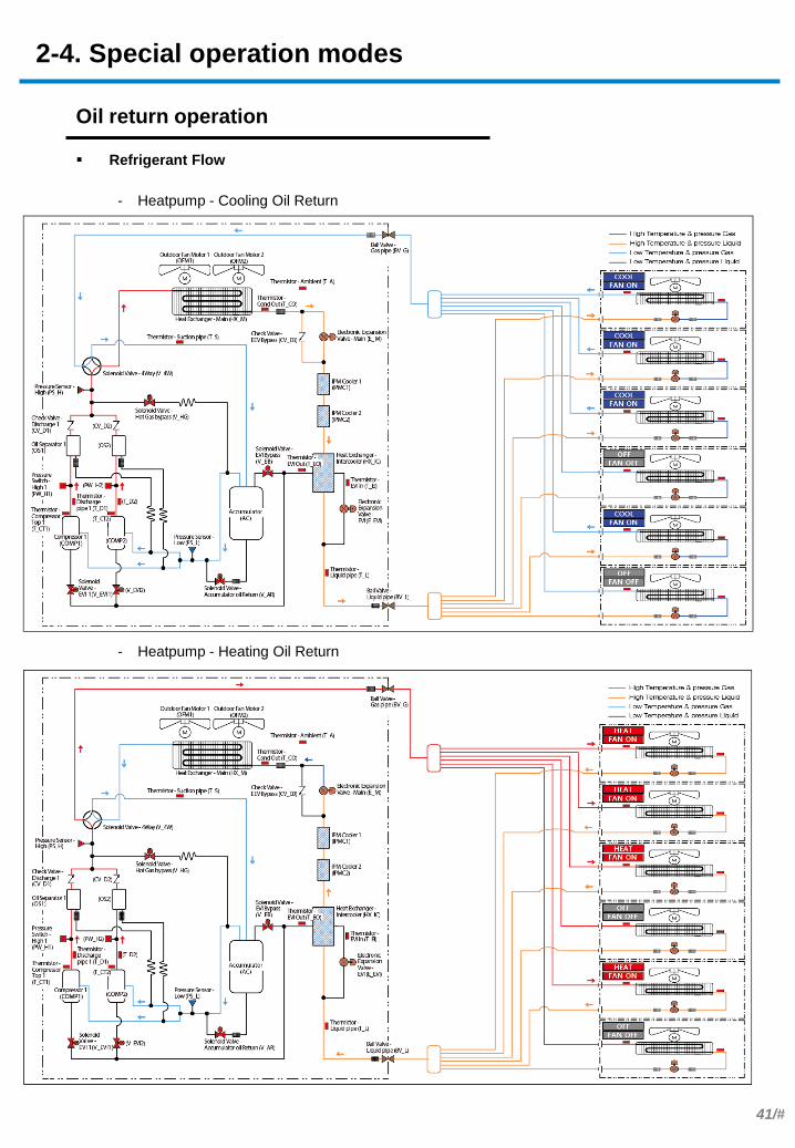
Oil return operation
Purpose
Concept
- Oil recovery operation shall be performed to prevent a compressor from being short of oil. Oil in
pipes or indoor unit will be collected to outdoor unit by starting oil collecting operation.
- Oil collecting operation will begin 7 hours after outdoor unit starts to operate but time might be
reduced depending on the operating condition (# of compressor in operation and operating
frequency). Once defrosting operation operate for more than 3 minutes during heating operation, it
will be considered to have done oil collecting operation.
- Master outdoor unit will be changed after oil collecting operation.
- The compressor capacity is raised to increase the amount of refrigerant circulation. This will return
oil remaining in indoor units and piping.
- EEVs are opened in a controller manner for active and inactive indoor units to facilitate oil return.
Control specifications in detail
- Perform oil return after a specified amount of time has elapsed in order to prevent an insufficient
amount of oil in compressors.
Actuator Oil return Operation
Capacity of compressor Current capacity + additional capacity
Outdoor EEV Normal control
Outdoor Fan Normal control
Indoor EEV
Operating indoor
units Higher step of [400(C)/300(H) or Current step]
Stopped indoor units 400(C)/300(H)
Indoor Fan Normal control
Time 3min(C) / 6min(H)
*Additional capacity = Compensation capacity of stop units
* EEV step can be varied by cycle condition.
2-4. Special operation modes
41/#
. .
Oil return operation
Refrigerant Flow
- Heatpump - Cooling Oil Return
- Heatpump - Heating Oil Return
2-4. Special operation modes

42/#
. .
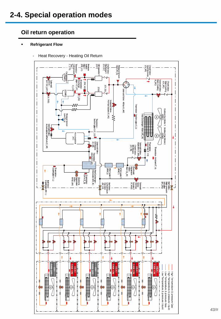
Oil return operation
Refrigerant Flow
- Heat Recovery - Cooling Oil Return
2-4. Special operation modes
43/#
Oil return operation
Refrigerant Flow
- Heat Recovery - Heating Oil Return
2-4. Special operation modes
44/#
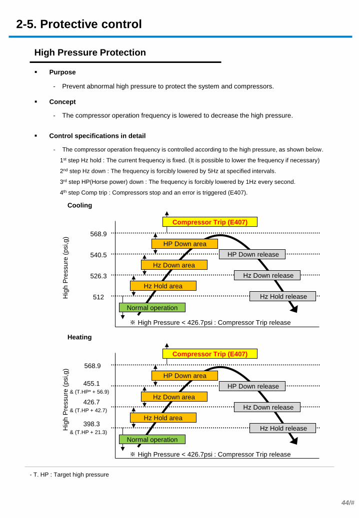
High Pressure Protection
Purpose
Concept
- The compressor operation frequency is controlled according to the high pressure, as shown below.
1st step Hz hold : The current frequency is fixed. (It is possible to lower the frequency if necessary)
2nd step Hz down : The frequency is forcibly lowered by 5Hz at specified intervals.
3rd step HP(Horse power) down : The frequency is forcibly lowered by 1Hz every second.
4th step Comp trip : Compressors stop and an error is triggered (E407).
- The compressor operation frequency is lowered to decrease the high pressure.
Control specifications in detail
- Prevent abnormal high pressure to protect the system and compressors.
Compressor Trip (E407)
※ High Pressure < 426.7psi : Compressor Trip release
Hz Hold area
Hz Down area
HP Down area
Normal operation
Hz Hold release 512
Hz Down release 526.3
HP Down release 540.5
568.9
Hig
h P
ressure
(psi,g)
Cooling
Compressor Trip (E407)
※ High Pressure < 426.7psi : Compressor Trip release
Hz Hold area
Hz Down area
HP Down area
Normal operation
Hz Hold release
Hz Down release
HP Down release 455.1
& (T.HP* + 56.9)
568.9
Hig
h P
ressure
(psi,g)
Heating
426.7
& (T.HP + 42.7)
398.3
& (T.HP + 21.3)
2-5. Protective control
- T. HP : Target high pressure
45/#
Low Pressure Protection
Purpose
Concept
- Control of the operation frequency (see the chart in the previous page for pressure
conditions.)
1st step Hz hold : Fix the current frequency if the discharge temperature is higher than
158℉. (It is possible to lower the frequency)
2nd step Hz down : Automatically lower the frequency by 5Hz at specified intervals if the
discharge temperature is higher than 158℉.
3rd step HP down : Automatically lower the frequency by 1Hz every second if the discharge
temperature is higher than 158℉
4th step Comp trip : If in critical state for 3 min, stop the compressors and trigger an error
(E410).
- Control of the Hot Gas Bypass Valve
Open the valve if low pressure is 45.5psi,g or lower in cooling mode OR below 12.8psi,g
in heating mode.
Close the valve if low pressure is 59.7psi,g or higher in cooling mode OR if low pressure
is 24.2psi,g or higher in heating mode.
- Others
If the outdoor temperature is abnormally low, limit opening of the valve. This reduces the
need to repeatedly turn on the low pressure protective control.
When cooling mode is on and the ambient temperature is 59℉ or lower, one of the Hz
Hold through HP Down steps is activated if the low pressure is -14.2psi.
- The compressor operation frequency is lowered to increase the low pressure.
- The Hotgas Bypass Valve is opened to bypass the high pressure to the suction pipe. This
will increase the high pressure.
Control specifications in detail
- Prevent abnormal low pressure to protect the system and compressors.
2-5. Protective control

46/#
Low Pressure Protection
※ Ta = Ambient Temperature
Low
Pre
ssure
(psi,g)
Heating ※ Compressor Trip release : Low Pressure >42.7psi for 3 min
Cooling
2-5. Protective control
Normal Operation
HP Down area
Hz Down area
Hz Hold area
Compressor trip (E410) after staying
in this phase for a max of 3 min
HP Down release
Hz Down release
Hz Hold release
Normal Operation
HP Down area
Hz Down area
Hz Hold area
Compressor trip (E410) after staying
in this phase for a max of 3 min
HP Down release
Hz Down release
Hz Hold release
7.1
Ta ≤ 14℉, 10.0 14℉ < Ta ≤ 32℉, 17.1 32℉ < Ta , 19.9
Ta ≤ 14℉, 14.2 14℉ < Ta ≤ 32℉, 22.8 32℉ < Ta , 31.3
Ta ≤ 14℉, 17.1 14℉ < Ta ≤ 32℉, 28.4 32℉ < Ta , 42.7
25.6
37
49.8
56.9
Low
Pre
ssure
(psi,g)
47/#
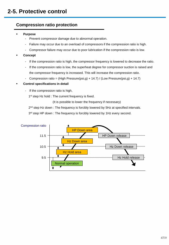
Compression ratio protection
Purpose
Concept
- If the compression ratio is high,
1st step Hz hold : The current frequency is fixed.
(It is possible to lower the frequency if necessary)
2nd step Hz down : The frequency is forcibly lowered by 5Hz at specified intervals.
3rd step HP down : The frequency is forcibly lowered by 1Hz every second.
- If the compression ratio is high, the compressor frequency is lowered to decrease the ratio.
- If the compression ratio is low, the superheat degree for compressor suction is raised and
the compressor frequency is increased. This will increase the compression ratio.
- Compression ratio = (High Pressure(psi,g) + 14.7) / (Low Pressure(psi,g) + 14.7)
Control specifications in detail
- Prevent compressor damage due to abnormal operation.
- Failure may occur due to an overload of compressors if the compression ratio is high.
- Compressor failure may occur due to poor lubrication if the compression ratio is low.
Compression ratio
Hz Hold area
Hz Down area
HP Down area
Normal operation
Hz Hold release 9.5
Hz Down release 10.5
HP Down release 11.5
2-5. Protective control
48/#
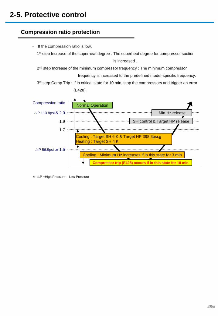
Compression ratio protection
- If the compression ratio is low,
1st step Increase of the superheat degree : The superheat degree for compressor suction
is increased .
2nd step Increase of the minimum compressor frequency : The minimum compressor
frequency is increased to the predefined model-specific frequency.
3rd step Comp Trip : If in critical state for 10 min, stop the compressors and trigger an error
(E428).
Normal Operation
Cooling : Target SH 6 K & Target HP 398.3psi,g
Heating : Target SH 4 K
Cooling : Minimum Hz increases if in this state for 3 min
Compressor trip (E428) occurs if in this state for 10 min
△P 56.9psi or 1.5
1.7
SH control & Target HP release 1.9
△P 113.8psi & 2.0 Min Hz release
Compression ratio
※ △P =High Pressure – Low Pressure
2-5. Protective control
49/#
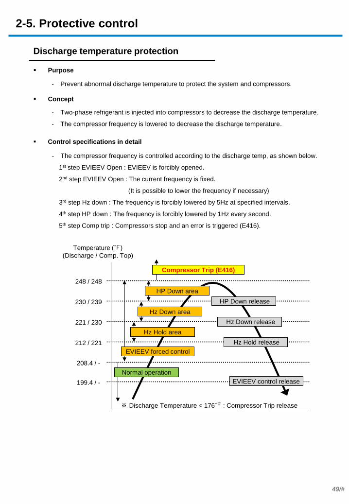
Discharge temperature protection
Purpose
Concept
- The compressor frequency is controlled according to the discharge temp, as shown below.
1st step EVIEEV Open : EVIEEV is forcibly opened.
2nd step EVIEEV Open : The current frequency is fixed.
(It is possible to lower the frequency if necessary)
3rd step Hz down : The frequency is forcibly lowered by 5Hz at specified intervals.
4th step HP down : The frequency is forcibly lowered by 1Hz every second.
5th step Comp trip : Compressors stop and an error is triggered (E416).
- Two-phase refrigerant is injected into compressors to decrease the discharge temperature.
- The compressor frequency is lowered to decrease the discharge temperature.
Control specifications in detail
- Prevent abnormal discharge temperature to protect the system and compressors.
Compressor Trip (E416)
※ Discharge Temperature < 176℉ : Compressor Trip release
Hz Hold area
Hz Down area
HP Down area
Normal operation
Hz Hold release 212 / 221
Hz Down release 221 / 230
HP Down release 230 / 239
248 / 248
Temperature (℉)
(Discharge / Comp. Top)
208.4 / -
199.4 / -
EVIEEV forced control
EVIEEV control release
2-5. Protective control

50/#
DSH (Discharge Super Heat) protection
Purpose
Concept
- The compressor Suction Super Heat (SH) is raised to increase the DSH.
- DSH = Compressor discharge temp. – High pressure saturation temp.
- The compressor discharge temperature is defined during DSH protection control :
Min { Max(Tdis_comp1, Ttop_comp1), Max(Tdis_comp2, Ttop_comp2) }
Control specifications in detail
- Prevent liquid compression to protect the system and compressors.
Enthalpy
Pre
ssure
Ph-Diagram
After DSH protection
Before DSH protection
DSH increase
SH increase
Normal Operation
If in this state for 30 sec,
Cooling : Indoor unit EEV Target SH 6 K
Heating : Main EEV Target SH 6 K
10
15
20
DSH (K) First heating release: the target SH is 3 K if in this state for 30 sec
Second heating release: SH release occurs 2 min after the first release
if the DSH is below 15 K
First cooling release: the target SH is 3 K if in this state for 30 sec
Second cooling release: SH release occurs 2 min after the first release
if the DSH is above 10 K
2-5. Protective control
- The target superheat changes to 6 K if the DSH is 10 K or lower.
51/#
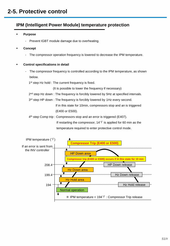
IPM (Intelligent Power Module) temperature protection
Purpose
Concept
- The compressor operation frequency is lowered to decrease the IPM temperature.
- Prevent IGBT module damage due to overheating.
- The compressor frequency is controlled according to the IPM temperature, as shown
below.
1st step Hz hold : The current frequency is fixed.
(It is possible to lower the frequency if necessary)
2nd step Hz down : The frequency is forcibly lowered by 5Hz at specified intervals.
3rd step HP down : The frequency is forcibly lowered by 1Hz every second.
If in this state for 10min, compressors stop and an is triggered
(E400 or E500).
4th step Comp trip : Compressors stop and an error is triggered (E407).
If restarting the compressor, 14℉ is applied for 60 min as the
temperature required to enter protective control mode.
Control specifications in detail
Compressor Trip (E400 or E500)
※ IPM temperature < 194℉ : Compressor Trip release
Hz Hold area
Hz Down area
HP Down area
Normal operation
Hz Hold release 194
Hz Down release 199.4
HP Down release 208.4
If an error is sent from
the INV controller
IPM temperature (℉)
Compressor trip (E400 or E500) occurs if in this state for 10 min
2-5. Protective control
52/#
Maximum current limit (total)
Purpose
Concept
- The compressor operation frequency is lowered to prevent the electric current used to
operate outdoor units from exceeding the maximum electric current.
- Outdoor unit current = Compressor current + Outdoor fan current (= CT1 + CT2)
※ CT1 = Compressor 1 current + Fan current
- Maximum outdoor unit current = Maximum current of the system x Set value
- Set value : 50-100% (default 100%). The value can be set from outdoor unit options or the
upper-level controller. A value below 100% will degrade performance.
- Prevent operation if the electric current capacity is exceeded.
- The frequency is controlled according to the outdoor unit current, as shown below.
1st step Hz hold : The current frequency is fixed if the outdoor unit current at present is
higher than 95% of the maximum current.
(It is possible to lower the frequency if necessary)
2nd step Hz down : The frequency is forcibly lowered by 5Hz at specified intervals
if the outdoor unit current at present is higher than the maximum current.
Control specifications in detail
2-5. Protective control

53/#
Maximum current limit (each compressor)
Purpose
Concept
- The compressor operation frequency is controlled to prevent each INV PBA input current
(CT) from exceeding the designed current limit.
- The compressor operation temperature is controlled to prevent each INV PBA output
current (OCT) from exceeding the designed current limit.
- Prevent device damage due to excess current in circuit components or overheating of the
IPM module.
- The compressor frequency is controlled according to the INV PBA input current (CT) for
each compressor, as shown below.
1st step Hz hold: The current frequency is fixed.
(It is possible to lower the frequency if necessary)
2nd step HP down: The frequency is forcibly lowered by 1Hz at specified intervals.
3RD step Comp trip: Compressors stop and an error is triggered (E462).
- The compressor frequency is controlled according to the INV PBA output current (OCT)
for each compressor, as shown below.
1st step Hz hold: The current frequency is fixed.
(It is possible to lower the frequency if necessary)
2nd step HP down: The frequency is forcibly lowered by 1Hz at specified intervals.
3RD step Comp trip: Compressors stop and an error is triggered (E462).
Control specifications in detail
CT(A)
Hz Hold area
HP Down area
Normal operation
Hz Hold release Hz hold
Ampere
HP Down release HP Down
Ampere
Comp Trip
Ampere
Compressor Trip (E462)
OCT(A)
Hz Hold area
HP Down area
Normal operation
Hz Hold release Hz Down
Ampere
HP Down release HP Down
Ampere
If an error is sent from
the INV controller
Compressor Trip (E464, 465, 364, 365)
2-5. Protective control

54/#
Freezing prevention
Purpose
Concept
- Frost is detected based on the temperature of indoor unit heat exchangers.
- Temperature of HX_ID* is defined during freezing prevention control :
Min { (temperature at the inlet of HX_ID), (temperature at the outlet of HX_ID outlet) }
- The compressor frequency is lowered to prevent frost in indoor unit heat exchangers.
- Prevent frost in indoor units to protect compressors. Prevent other accidents.
- If there is frost in indoor units, refrigerant will not evaporate. As a result, compressor
failure will occur due to liquid compression.
- If there is frost in indoor units, ice may form and fall causing an accident.
Control specifications in detail
Normal Operation
, HP Down area if in this state for 40 sec
Hz Down area if in this state for 40 sec
Hz Hold area if in this state for 40 sec
Compressor Stop & Indoor unit air flow = low if in this state for 40 sec
24.8
28.4
32
35.6
Temperature (℉)
39.2 Hz Hold & HP down release
44.6 Compressor Stop & air flow release
- The compressor operation frequency is controlled according to the temperature of indoor
unit heat exchangers, as shown below.
1st step Hz hold : The current frequency is fixed. (It is possible to lower the frequency if
necessary)
2nd step Hz down : The frequency is forcibly lowered by 5Hz at specified intervals.
3rd step HP(Horse power) down : The frequency is forcibly lowered by 1Hz every second.
4th step Comp stop : Compressors stop and the fan speed changes for indoor units to the
mid level.
2-5. Protective control
- HX_ID : Indoor unit heat exchanger
55/#
. .
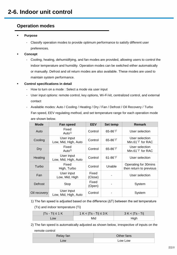
- How to turn on a mode : Select a mode via user input
- User input options: remote control, key options, Wi-Fi kit, centralized control, and external
contact
- Available modes: Auto / Cooling / Heating / Dry / Fan / Defrost / Oil Recovery / Turbo
Fan speed, EEV regulating method, and set temperature range for each operation mode
are shown below.
1) The fan speed is adjusted based on the difference (ΔT) between the set temperature
(Ts) and indoor temperature (Ti)
2) The fan speed is automatically adjusted as shown below, irrespective of inputs on the
remote control
Operation modes
Mode Fan speed EEV Set temp Remark
Auto Fixed
Auto1) Control 65-86℉ User selection
Cooling User input
Low, Mid, High, Auto Control 65-86℉
User selection
Min.61℉ for RAC
Dry Fixed
Auto2) Control 65-86℉
User selection
Min.61℉ for RAC
Heating User input
Low, Mid, High, Auto Control 61-86℉ User selection
Turbo Fixed
High, Turbo Control Unable
Operating for 30mins
then return to previous
Fan User input
Low, Mid, High
Fixed
(Close) - User selection
Defrost Stop Fixed
(Open) - System
Oil recovery User input
Low, Mid, High, Auto Control - System
|Ts - Ti| ≤ 1 K 1 K < |Ts - Ti| ≤ 3 K 3 K < |Ts - Ti|
Low Mid High
Relay fan Other fans
Low Low Low
2-6. Indoor unit control
Purpose
Concept
- Cooling, heating, dehumidifying, and fan modes are provided, allowing users to control the
indoor temperature and humidity. Operation modes can be switched either automatically
or manually. Defrost and oil return modes are also available. These modes are used to
maintain system performance.
- Classify operation modes to provide optimum performance to satisfy different user
preferences.
Control specifications in detail
56/#
- How to turn on the mode : Select the mode via user input
- User input options : Remote control, key options, Wi-Fi kit, centralized control, and
external contact
- Operation specifications : Cooling or heating mode is selected based on the difference
between the set temperature and indoor temperature, as shown
below.
- It is possible to change the operation mode 30 minutes after Thermo-off. The mode can
also be changed after changing the set temperature.
- The operation mode changes using the initial operation setting method if one indoor unit is
active. The outdoor unit operation mode is maintained if two or more indoor units are
active. These occur 30 minutes after Thermo-off.
1) When Auto Changeover options are configured
2) The operation mode changes according to the initial operation mode setting conditions
- On the HR model, the operation mode changes if the set temperature is changed, as
shown below.
3) HR Only
4) ΔT : Represents the heating compensation temperature. It is affected by the offset
associated with room temperature compensation or heating configuration compensation.
Initial operation mode
setting
Room - Set Temp. ≥ - 1 K Room - Set Temp. < - 1 K
Cooling Heating
Changing the
operation mode
30 minutes after Thermo-off1)
If one indoor unit is active If two or more indoor units
are active
Switch between cooling and
heating modes2)
Maintain outdoor unit
operation mode
Changing the
operation mode
After changing the set temperature3)
If auto cooling mode is on If auto heating mode is on
Set room temp. < - 1 K Set room temp. ≥ 1 K+ΔT4)
Switch to auto heating mode Switch to auto cooling mode
2-6. Indoor unit control
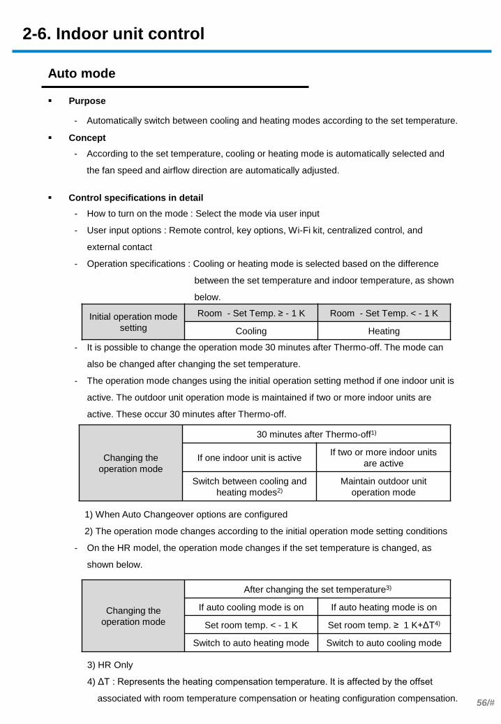
Auto mode
Purpose
Concept
- According to the set temperature, cooling or heating mode is automatically selected and
the fan speed and airflow direction are automatically adjusted.
- Automatically switch between cooling and heating modes according to the set temperature.
Control specifications in detail

57/#
Sym
bol Function 0 1 2 3 4 5 6 7
A Offset the set heating
temp 0 0.5 1 1.5 2 2.5 3 3.5
B Offset the set cooling
temp 0 0.5 1 1.5 2 2.5 3 3.5
C Change the mode
(heat→cool) 1 1.5 2 2.5 3 3.5 4 4.5
D Change the mode
(cool→heat) 1 1.5 2 2.5 3 3.5 4 4.5
T T time 5 7 9 11 13 15 20 30
1. Initial operation mode determination
If Tr ≥ Ts - A + 1 K If Tr < Ts – A + 1 K
Auto Cooling Auto Heating
2. Mode change
Cooling → Heating Heating→ Cooling
Thermo off for T & Tr < Ts - D Thermo off for T & Tr ≥ Ts + C
3. Thermo On/Off
In cooling mode In heating mode
Thermo on : Tr ≥ Ts + B + 1 K
Thermo off : Tr < Ts + B – 1 K
Thermo on : Tr < Ts - A – 1 K
Thermo off : Tr ≥ Ts - A + 1 K
2-6. Indoor unit control
- Install Option 2 value
Auto Change Over
Purpose
Concept
- How to turn on the mode : Select Auto Changeover
- Heating or cooling mode automatically turns on after comparing the indoor temperature
(Tr) with the set temperature (Ts). It is possible to adjust the Auto Changeover condition
according to the value of installation option 2.
- Automatically turn on heating or cooling mode according to the indoor temperature when
using auto mode(HR model only).
Control specifications in detail
58/#
. .
Tset
Tset – 1 K
on
Thermo off
Thermo on
Thermo off
Tset + △T
Tset – 1 K + △T
on
Thermo off
Thermo on
Thermo off
Cooling
Heating
2-6. Indoor unit control
- Cooling mode
Thermo on:
Room temp. ≥ Set temp.
Room temp. ≥ Set temp.+1 K (RAC only)
Thermo off:
Room temp. ≤ Set temp. -1 K
Room temp. ≤ Set temp (RAC only)
- Heating mode
Thermo on:
Room temp. ≤ Set temp. -1 K+ △T*
Thermo off:
Room temp. ≥ Set temp. + △T
*△T: Please refer to the next page for Heating compensation temperature)
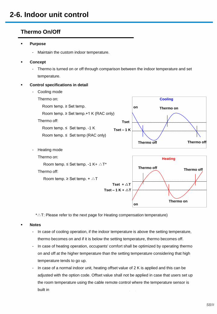
Purpose
Concept
- Thermo is turned on or off through comparison between the indoor temperature and set
temperature.
- Maintain the custom indoor temperature.
Control specifications in detail
Thermo On/Off
- In case of cooling operation, if the indoor temperature is above the setting temperature,
thermo becomes on and if it is below the setting temperature, thermo becomes off.
- In case of heating operation, occupants' comfort shall be optimized by operating thermo
on and off at the higher temperature than the setting temperature considering that high
temperature tends to go up.
- In case of a normal indoor unit, heating offset value of 2 K is applied and this can be
adjusted with the option code. Offset value shall not be applied in case that users set up
the room temperature using the cable remote control where the temperature sensor is
built in
Notes

59/#
- Factory default (product option code SEG6)
- 4way type : △T* = 5 K
- others : △T* = 2 K
- Installation setting( installation option code SEG21)
* △T: Heating compensation temperature
- In case of using external room temp. sensor( Installation option SEG4 = 1 ) : △T = 0
SEG21 Setting △T*
0 Factory default
1 2 K
2 5 K
2-6. Indoor unit control
Purpose
Concept
- If measuring the indoor temperature using the internal temp sensors on indoor units in
heating mode, the temperature is controlled under the assumption that the actual indoor
temperature is lower than the temperature inside the indoor units and the temperature
difference is equivalent to the compensation temperature.
- Compensate for variances in temperature affecting people differently in the room. Wind
chill is caused by indoor temperature stratification when using the internal temp sensors
on indoor units instead of using external temp sensors in the room.
Control specifications in detail
Temperature Compensation
- Order of priority : Use of external temp sensor > Install offset > Basic option
Notes
80℉
77℉
60/#
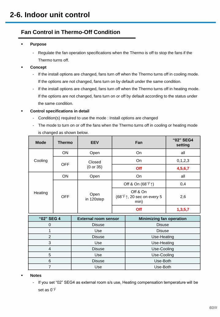
Mode Thermo EEV Fan “02” SEG4
setting
Cooling
ON Open On all
OFF Closed
(0 or 35)
On 0,1,2,3
Off 4,5,6,7
Heating
ON Open On all
OFF Open
in 120step
Off & On (68℉↑) 0,4
Off & On
(68℉↑, 20 sec on every 5
min)
2,6
Off 1,3,5,7
“02” SEG 4 External room sensor Minimizing fan operation
0 Disuse Disuse
1 Use Disuse
2 Disuse Use-Heating
3 Use Use-Heating
4 Disuse Use-Cooling
5 Use Use-Cooling
6 Disuse Use-Both
7 Use Use-Both
2-6. Indoor unit control
- Condition(s) required to use the mode : Install options are changed
- The mode to turn on or off the fans when the Thermo turns off in cooling or heating mode
is changed as shown below.
Purpose
Concept
- If the install options are changed, fans turn off when the Thermo turns off in cooling mode.
If the options are not changed, fans turn on by default under the same condition.
- If the install options are changed, fans turn off when the Thermo turns off in heating mode.
If the options are not changed, fans turn on or off by default according to the status under
the same condition.
- Regulate the fan operation specifications when the Thermo is off to stop the fans if the
Thermo turns off.
Control specifications in detail
Fan Control in Thermo-Off Condition
- If you set “02” SEG4 as external room s/s use, Heating compensation temperature will be
set as 0℉
Notes
61/#
. .
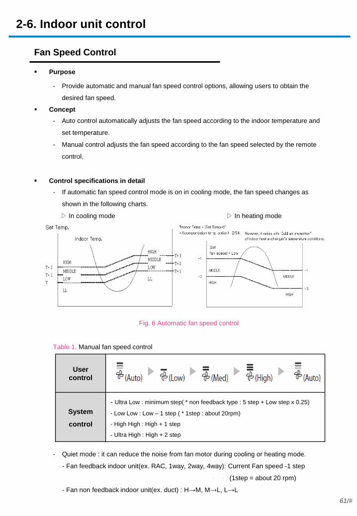
2-6. Indoor unit control
- If automatic fan speed control mode is on in cooling mode, the fan speed changes as
shown in the following charts.
▷ In cooling mode ▷ In heating mode
Fig. 6 Automatic fan speed control
Table 1. Manual fan speed control
- Quiet mode : it can reduce the noise from fan motor during cooling or heating mode.
- Fan feedback indoor unit(ex. RAC, 1way, 2way, 4way): Current Fan speed -1 step
(1step = about 20 rpm)
- Fan non feedback indoor unit(ex. duct) : H→M, M→L, L→L
Purpose
Concept
- Auto control automatically adjusts the fan speed according to the indoor temperature and
set temperature.
- Manual control adjusts the fan speed according to the fan speed selected by the remote
control.
- Provide automatic and manual fan speed control options, allowing users to obtain the
desired fan speed.
Control specifications in detail
Fan Speed Control
User
control
System
control
- Ultra Low : minimum step( * non feedback type : 5 step + Low step x 0.25)
- Low Low : Low – 1 step ( * 1step : about 20rpm)
- High High : High + 1 step
- Ultra High : High + 2 step

62/#
. .
Gas
Condensed liquid
Hot gas
Condensed liquid
ON ON OFF
ON ON OFF
Cooling
Heating
EEV 120 step
EEV 0step
2-6. Indoor unit control
- Condition(s) required to use modes
- General control : Thermos on indoor units are on
- Inactive indoor unit EEV control: (Comp OFF) or (Comp ON and Indoor unit Thermo-OFF)
- Operation specifications
- General control: Control is performed with the superheat degree at the exit of indoor heat
exchanges in cooling mode. In heating mode, control is performed with the subcooling
degree.
- Inactive indoor unit EEV control: Control is performed as shown in the following table.
* Note 1 : Control of inactive heating units (lower noise/general)
Purpose
Concept
- General control: Control is performed with the superheat degree in cooling mode. In
heating mode, control is performed with the subcooling degree.
- Inactive indoor unit control: The gas pipe is kept open slightly in heating mode to prevent
refrigerant from stagnating in the piping.
- General control: Maintain the amount of refrigerant flowing into the indoor units at the
appropriate level.
- Inactive indoor unit control: Prevent insufficient refrigerant due to refrigerant stagnating in
the piping connected to inactive indoor units.
Control specifications in detail
Electronic Expansion Valve(EEV) Control
Outdoor unit operation COMP ON COMP OFF
Indoor unit operation Cooling Heating COMP stops
- 3 min
COMP stops
3 - 5 min
COMP stops
5 min
elapses
(Auto) cooling
/Dehumidification
/Fan
Thermo On Cooling EEV control 0 0 35
Thermo Off 0 Note 1* 0 0 35
(Auto) heating Operation On Heating EEV control 35 35 35
Operation Off 0 Note 1* 35 35 35
Outdoor unit for first priority
outdoor unit CAM EDM high-head EDM general
32℉ or lower 80 130 200
Above 32℉ 80 120 180
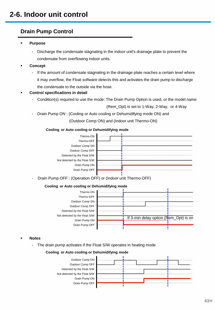
63/#
2-6. Indoor unit control
- Condition(s) required to use the mode: The Drain Pump Option is used, or the model name
(Rem_Opt) is set to 1-Way, 2-Way, or 4-Way
- Drain Pump ON : (Cooling or Auto cooling or Dehumidifying mode ON) and
(Outdoor Comp ON) and (Indoor unit Thermo-ON)
- Drain Pump OFF : (Operation OFF) or (Indoor unit Thermo OFF)
Purpose
Concept
- If the amount of condensate stagnating in the drainage plate reaches a certain level where
it may overflow, the Float software detects this and activates the drain pump to discharge
the condensate to the outside via the hose.
- Discharge the condensate stagnating in the indoor unit's drainage plate to prevent the
condensate from overflowing indoor units.
Control specifications in detail
Drain Pump Control
- The drain pump activates if the Float S/W operates in heating mode
Notes
Cooling or Auto cooling or Dehumidifying mode
If 3-min delay option (Rem_Opt) is on
Cooling or Auto cooling or Dehumidifying mode
Cooling or Auto cooling or Dehumidifying mode
Thermo-ON
Thermo-OFF
Outdoor Comp ON
Outdoor Comp OFF
Detected by the Float S/W
Not detected by the Float S/W
Drain Pump ON
Drain Pump OFF
Thermo-ON
Thermo-OFF
Outdoor Comp ON
Outdoor Comp OFF
Detected by the Float S/W
Not detected by the Float S/W
Drain Pump ON
Drain Pump OFF
Outdoor Comp ON
Outdoor Comp OFF
Detected by the Float S/W
Not detected by the Float S/W
Drain Pump ON
Drain Pump OFF

64/#
68.0℉
78.8℉
86.0℉
89.6℉
93.2℉
100.4℉
Low
Mid or lower
High or lower
High or lower
Low
Mid or lower
82.4℉
96.8℉
Low Low
Low Low
Fan off
Fan off
Eva
p. avg
. Tem
p.
Airflow in heating mode
If the temp drops
If the temp rises
2-6. Indoor unit control
- Condition(s) required to use the mode : Indoor units are operating in heating mode
- The fan speed is restricted according to the average heat exchanger temperature and
temperature variations (increase/decrease).
Purpose
Concept
- The fan does not operate if the indoor heat exchanger temperature is low in heating mode.
The fan speed is restricted if the temperature is low.
- Control the fan speed to avoid discomfort of people in the room due to cold air in cooling
mode or during the initial start-up of heating.
Control specifications in detail
Cold Air Prevention
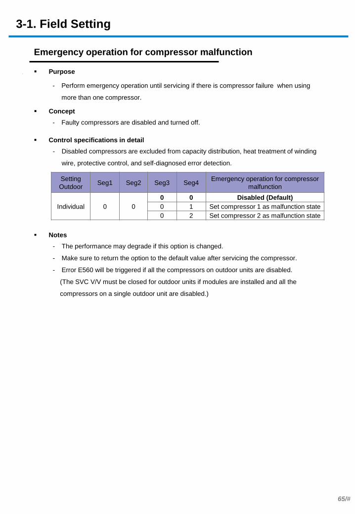
65/#
.
Setting
Outdoor Seg1 Seg2 Seg3 Seg4
Emergency operation for compressor
malfunction
Individual 0 0
0 0 Disabled (Default)
0 1 Set compressor 1 as malfunction state
0 2 Set compressor 2 as malfunction state
3-1. Field Setting
- Disabled compressors are excluded from capacity distribution, heat treatment of winding
wire, protective control, and self-diagnosed error detection.
Purpose
Concept
- Faulty compressors are disabled and turned off.
- Perform emergency operation until servicing if there is compressor failure when using
more than one compressor.
Control specifications in detail
Emergency operation for compressor malfunction
- The performance may degrade if this option is changed.
- Make sure to return the option to the default value after servicing the compressor.
- Error E560 will be triggered if all the compressors on outdoor units are disabled.
(The SVC V/V must be closed for outdoor units if modules are installed and all the
compressors on a single outdoor unit are disabled.)
Notes
66/#
Input unit Seg1 Seg2 Seg3 Seg4 Temperature(℉)
Main 0 1
0 0 44.6 – 48.2
0 1 41 – 44.6 (default)
0 2 48.2 – 51.8
0 3 50 – 53.6
0 4 51.8 – 55.4
0 5 53.6 – 57.2
0 6 55.4 - 59
3-1. Field Setting
- The target low pressure for outdoor units and the compressor operation frequency are
controlled according to the Target Evap In Temp. that was configured in cooling mode.
- See “Compressor capacity control" for details on compressor operation specifications.
Purpose
Concept
- The Target Evap In temperature is changed to control the low pressure in cooling mode.
- Control the cooling performance.
Control specifications in detail
Cooling capacity correction
- When low temperature value is set, discharged air temperature of the indoor unit will
decrease.
Notes

67/#
Input
unit Seg1 Seg2 Seg3 Seg4 pressure(psi,g)
Main 0 2
0 0 426.7 (default)
0 1 355.6
0 2 369.8
0 3 384
0 4 398.3
0 5 412.5
0 6 440.9
0 7 455.1
0 8 469.4
3-1. Field Setting
- The high pressure for outdoor units and the compressor operation frequency are
controlled according to the Target high pressure that was configured in cooling mode.
- See “Compressor capacity control" for details on compressor operation specifications.
Purpose
Concept
- The Target high pressure is changed to control the pressure in heating mode.
- Control the heating performance.
Control specifications in detail
Heating capacity correction
- When low pressure value is set, discharged air temperature of the indoor unit will
decrease and power of outdoor will increase.
Notes

68/#
Input
unit Seg1 Seg2 Seg3 Seg4 Current restriction rate
Individual 0 3
0 0 100% (default)
0 1 95%
0 2 90%
0 3 85%
0 4 80%
0 5 75%
0 6 70%
0 7 65%
0 8 60%
0 9 55%
1 0 50%
1 1 No restriction
3-1. Field Setting
- The maximum current for outdoor units is restricted according to the current ratio that was
configured while in cooling or heating mode.
- See "Maximum current limit (total)" for details.
Purpose
Concept
- The max electric current (50% - 100%) is restricted.
- Reduce the electric current used for operation.
Control specifications in detail
Current restriction rate
- When current restriction option is set, cooling and heating performance may decrease and
power of outdoor will increase.
- To set no restriction, make sure to contact an expert install service provider. Outdoor units
operate with an abnormal current.
This may affect the power and operation. The electric current protective control remains
on to protect the units.
Notes

69/#
3-1. Field Setting
- Oil recovery is performed at the halved oil return interval.
- See "Oil return operation" for details on oil return operation specifications.
Purpose
Concept
- The oil return cycle is shortened by half.
- Protect the system in the event of an oil leak.
Control specifications in detail
Oil collection interval
- Change the option if an oil leak occurs. Performance may degrade if the option is not
changed.
- Make sure to restore the original value after refilling the oil.
Notes
Input unit Seg1 Seg2 Seg3 Seg4 Oil collection interval
Main 0 4 0 0 Standard (default)
0 1 Shorten the interval by 1/2

70/#
Option is configured
Amount of frost formed
Cond out, Suction
Time
Outdoor temp
Option is not configured
Input
unit Seg1 Seg2 Seg3 Seg4 Temperature to trigger defrost operation
Main 0 5
0 0 Standard (default)
0 1 Apply setting when the product is installed in a
humid area such as near river or lake
3-1. Field Setting
- Defrost operation is performed if the amount of frost that formed is smaller than the option
setting when the heat exchangers are checked for frost formation based on the difference
between the outdoor temperature and heat exchanger temperature (Cond out, Suction)
- See “Defrost control” for details on defrost operation specifications.
Purpose
Concept
- Defrost operation is performed frequently if there is frost formation on heat exchangers in
heating mode.
- Prevent excessive frost formation in a high-humidity condition.
(Apply setting when the product is being installed in a humid area such as near a river or
lake.)
Control specifications in detail
Temperature to trigger defrost operation
- If this option is configured and the units are in a very humid location, heating performance
may degrade due to frequent defrost operation.
Notes
71/#
Input
unit Seg1 Seg2 Seg3 Seg4
Fan speed correction for
outdoor unit
Individual 0 6 0 0 Standard (default)
0 1 Increase fan speed
3-1. Field Setting
- High pressure is controlled taking into account the maximum fan RPM.
- See "Fan control" for details on outdoor fan operation specifications.
Purpose
Concept
- The maximum fan RPM rises to the limit if this option is configured. (The RPM does not
change on some models.)
- Improve performance in cooling mode when the outdoor temperature is high or in heating
mode when the outdoor temperature is low .
Control specifications in detail
Fan speed correction for outdoor unit
- Noise level may increase as the maximum RPM rises.
- Do not configure this option if using units in a location that is outside the recommended
operation temperature (118.4℉) or permitted external static pressure
Notes

72/#
Input unit Seg1 Seg2 Seg3 Seg4 Silent mode for night - time
Main 0 7
0 0 Disabled (default)
0 1 LEVEL 1 / Auto
0 2 LEVEL 2 / Auto
0 3 LEVEL 3 / Auto
0 4 LEVEL 1 / External contact
0 5 LEVEL 2 / External contact
0 6 LEVEL 3 / External contact
Silent mode Noise level (dB)
Disabled SPEC
LEVEL 1 SPEC – 1/3*(SPEC-49)
LEVEL 2 SPEC – 2/3*(SPEC-49)
LEVEL 3 49
3-1. Field Setting
- The maximum compressor frequency and outdoor fan RPM decrease according to the
specified level.
- Silent mode automatically turns on according to the day/night temperature pattern if Auto
mode is on. If External contact is configured, silent mode turns on when the contact is on.
Purpose
Concept
- The maximum compressor frequency and the outdoor fan RPM are lowered.
(Noise level: Level 1 > Level 2 > Level 3)
- Auto mode : General and silent modes switch to each other automatically for day and night.
- External contact : Configure this option if using an interface module (MIM-B14).
Silent mode turns on if the external contact is on.
- Reduce the maximum operation noise when using units in an area sensitive to noise, such
as a residential area.
Control specifications in detail
Silent mode for night-time
- If the silent mode option is configured, the noise level decreases. However, performance
may degrade.
- Noise level according to the specified silent mode LEVEL
Notes
73/#
Input
unit Seg1 Seg2 Seg3 Seg4 High-head condition setting
Main 0 8
0 0 Disabled (default)
0 1 Level 1 of Type1 (When outdoor unit is
located 131~262ft above the indoor unit)
0 2 Level 2 of Type 1 (When outdoor unit is
located over 262ft above the indoor unit)
0 3 Type 2 (When indoor unit is over 98ft above
the outdoor unit)
3-1. Field Setting
- In Type 1 heating mode, the initial EEV opening degree increases. The compressor
frequency increase speed decreases if the low pressure is low (see "Main EEV control" for
details on EEV control).
- In Type 2 heating mode, the initial EEV opening degree decreases. The compressor
frequency increase speed decreases if the low pressure is low (see "Main EEV control" for
details on EEV control).
- In Type 2 cooling mode, the target high pressure for outdoor fans increases to 398.3psi
(see "Fan control" for details on controlling outdoor fans).
- In Type 1 and 2 cooling modes, EVI bypass mode turns on (see “EVI EEV control“ for
details).
Purpose
Concept
- Control of the compressor frequency, outdoor fans, EEV, and valves is optimized to
facilitate the circulation of refrigerant in any head condition.
- Secure performance and reliability when using units installed under a high-head condition.
Control specifications in detail
High-head condition setting
- Incorrect settings may damage the system.
Notes
74/#
Input
unit Seg1 Seg2 Seg3 Seg4 Long-piping condition setting
Main 0 9
0 0 Disabled (default)
0 1
Level 1 (When equivalent length of farthest
indoor unit from the outdoor unit is between
328~558ft)
0 2 Level 2 (When equivalent length of farthest
indoor unit from the outdoor unit is over 558ft)
3-1. Field Setting
- In heating mode, the initial EEV opening degree increases. The compressor frequency
increase speed decreases if the low pressure is low (see "Main EEV control" for details on
EEV control).
- In cooling mode, the initial value for target low pressure decreases to 99.6psi,g (see
“Compressor capacity control” for details).
- In cooling mode, EVI bypass mode turns on (see "EVI EEV control" for details).
Purpose
Concept
- Control of the compressor frequency, EEV, and valves is optimized to facilitate the
circulation of refrigerant in a long piping condition.
- Secure performance and reliability when the units are used with long piping.
Control specifications in detail
Long-piping condition setting
- Incorrect settings may seriously damage the system.
- Setting is unnecessary if high-head condition is set.
Notes

75/#
- Energy saving mode:
The compressor frequency is lowered by increasing the target evaporation temperature if
the maximum difference between the indoor temperature and set temperature among
active cooling indoor units is 3 K or lower.
(see “ Compressor capacity control” for details on controlling the compressor frequency).
The compressor frequency is lowered by decreasing the target high pressure if the
maximum difference between the indoor unit and set temperature among active heating
indoor units is 2 K or lower.
(see “Compressor capacity control” for details on controlling the compressor frequency).
Tem
pera
ture
Set temperature
Set temperature + 3 K
Target evaporation temperature
(when the outdoor temperature is high)
Target evaporation temperature
(when the outdoor temperature is low)
Current indoor temperature
ECO for cooling
Tem
pera
ture
, pre
ssure
Set temperature - 2 K
Set temperature
Target high pressure
Current indoor temperature
ECO for heating
3-1. Field Setting
Purpose
Concept
- Energy saving mode: The operation capacity is controlled based on the difference
between the indoor temperature and the set temperature for indoor units.
- Power mode: The initial target low pressure is lowered to increase the cooling speed in
cooling mode.
- Energy saving mode: Save energy by optimizing the operation load according to the
indoor and outdoor temperatures.
- Power mode: Quickly cool down the room by increasing the initial cooling speed.
Control specifications in detail
Energy control operation (ECO)
76/#
. . - Power mode: In cooling mode, the initial target low pressure is lowered to increase the
compressor frequency increase speed.
Input
unit Seg1 Seg2 Seg3 Seg4 Energy control Operation
Main 1 0
0 0 Disabled (default)
0 1 Energy saving
0 2 Power
Pre
ssu
re
Target low pressure (92.5psi,g
if power mode is enabled)
Target low pressure (113.8 psi,g by default)
Perf
orm
an
ce
Power mode enabled
Default
3-1. Field Setting
Energy control operation (ECO)
- Operating in energy saving mode, capacity might decrease compared to normal operation
mode.
Notes
77/#
Input
unit Seg1 Seg2 Seg3 Seg4 Rotation defrost
Main 1 1 0 0 Disabled (default)
0 1 Enabled
3-1. Field Setting
- In heating mode, defrost operation is performed on each unit one after another according
to the order of rotation priority
- (see "Rotation defrost control" for details).
Purpose
Concept
- Continuous heating is provided by performing defrost operation for each unit if HR
modules are used.
- HR Only
- Enable continuous heating when HR modules are used.
Control specifications in detail
Rotation defrost
- Heating performance will decrease during rotation defrost operation.
Notes

78/#
Input
unit Seg1 Seg2 Seg3 Seg4
Expand operational temperature
range for cooling operation (HR only)
Main 1 2 0 0 Disabled (default)
0 1 Enabled
3-1. Field Setting
- If it is difficult to secure outdoor high pressure while in cooling mode in an outdoor location
with a low temperature, formation of high pressure is facilitated by controlling the low
pressure decrease, Solenoid valve – Main EEV, and Solenoid valve – Hot gas bypass.
Purpose
Concept
- The cooling operation range is extended by controlling purpose-specific valves on HR
units
- HR Only
- Extend the low temperature operation range for HR units to 5℉.
Control specifications in detail
Expand operational temperature range for cooling
- Continuous cooling operation is possible even in low temperature condition up to 5℉, but
noise of the MCU will increase.
- This option is only for HR unit
Notes

79/#
Input
unit Seg1 Seg2 Seg3 Seg4 Channel address
Main 1 3
A U Automatic setting (default)
0 - 15 Manual setting for channel
0 - 15
3-1. Field Setting
Purpose
Concept
- If the Channel address is set, the same channel address is assigned to the sub outdoor
units, indoor units, and MCUs connected to a main outdoor unit.
- Identify multiple main outdoor units connected to upper-level controllers, such as DMS
and S-NET3.
Control specifications in detail
Channel address

80/#
Input
unit Seg1 Seg2 Seg3 Seg4
Snow accumulation
prevention control
Main 1 4 0 0 Enabled (default)
0 1 Disabled
3-1. Field Setting
- If a snow sensor is not installed, the outdoor fans operate in 3step mode for one min every
30 min if operation stops at an outdoor temperature of 41℉ or lower.
- If a snow sensor is installed and the sensor detects when operation stops at an outdoor
temperature of 41℉ or lower, the outdoor fans operate in 3 step for 10 sec and then
continue operation in a higher step for 50 sec.
Purpose
Concept
- Snow on top of outdoor units is removed by turning on outdoor fans if snow accumulation
is detected by the snow sensor or via the outdoor temperature.
- Prevent snow accumulation on inactive outdoor units to ensure normal operation (default
option).
Control specifications in detail
Snow accumulation prevention control
- During snow accumulation, the fan may spin even when the unit is not in operation.
- Outdoor fans may be turned on by this feature during servicing. Careful attention is
required
Notes

81/#
Input
unit Seg1 Seg2 Seg3 Seg4 Speed operation
Main 1 7 0 0 Disabled (default)
0 1 Enabled
3-1. Field Setting
- The frequency and increase speed are increased in Safety Start mode.
- The control speed is improved by changing the interval to control the target heating
pressure to 20 sec from 40 sec.
Purpose
Concept
- The cooling or heating speed is increased by raising the compressor frequency increase
speed.
- Enabling this setting will command the air conditioner to cool/heat faster at initial start-up.
Control specifications in detail
Speed operation
- This function will not work when High-head condition setting or Long-piping condition
setting is enabled.
Notes

82/#
Input
unit Seg1 Seg2 Seg3 Seg4 Max capacity restriction
Main 1 8 0 0 Enabled (default)
0 1 Disabled
3-1. Field Setting
- The maximum operation capacity is restricted, taking into account the capacity of indoor
units, set fan speed, outdoor temperature, and indoor temperature if the system cooling
operation status is within the normal operation range.
- The maximum cooling capacity is not restricted if the outdoor temperature is low and it is
difficult to secure low and high pressures.
Purpose
Concept
- The maximum capacity for outdoor units is restricted taking into account the capacity of
indoor units and the outdoor temperature.
- Prevent an excessive increase of compressor performance compared to the capacity of
indoor units (default option).
Control specifications in detail
Max capacity restriction