DVI MULTIPLEXER CHAMELEON OPERATION
33
Owner’s Manual HX Series HDMI Integrated Matrix Routers PureLink TM 535 East Crescent Avenue Ramsey, NJ 07446 USA Tel: +1.201.488.3232 Fax: +1.201.621.6118 E-mail: [email protected] www.purelinkav.com For order support, please contact your local dealer. For technical support, please contact us at [email protected]
Transcript of DVI MULTIPLEXER CHAMELEON OPERATION

Owner’s Manual
HX Series HDMI Integrated Matrix Routers
PureLinkTM
535 East Crescent Avenue
Ramsey, NJ 07446 USA
Tel: +1.201.488.3232 Fax: +1.201.621.6118
E-mail: [email protected] www.purelinkav.com
For order support, please contact your local dealer.
For technical support, please contact us at [email protected]

PureLink by Dtrovision
2
TABLE OF CONTENTS
Chapter 1. Product Overview
1.1 Safety Precautions --------------------------------------------------------------- 3
1.2 Declaration of Conformity --------------------------------------------------------------- 4
1.3 What’s in the Box --------------------------------------------------------------- 4
1.4 Product Introduction --------------------------------------------------------------- 5
1.5 Front View --------------------------------------------------------------- 6
1.6 Rear View --------------------------------------------------------------- 6
1.7 Installation Guidelines --------------------------------------------------------------- 11
Chapter 2. Product features
2.1 Features --------------------------------------------------------------- 12
Chapter 3. Operational guidelines
3.1 Main Menu User Guide --------------------------------------------------------------- 13
Chapter 4. Communication Code Configuration
4.1 Control Programmer’s Guide ---------------------------------------------------- 18
4.2 Overview ---------------------------------------------------------------------- 18
4.3 Command Code Formats ----------------------------------------------------------- 18
4.4 General Rules for Command Codes --------------------------------------------- 19
4.5 Command Ack Value Response ---------------------------------------------------- 21
4.6 Connecting Switches --------------------------------------------------------------- 21
4.7 Disconnecting Switches ----------------------------------------------------------- 22
4.8 Connection Status Check ----------------------------------------------------------- 23
4.9 Lan Code Configuration ----------------------------------------------------------- 25
Chapter 5. Firmware update instruction & Warranty Information
5.1 Firmware Update Instruction ------------------------------------------------------- 26
Chapter 6. Additional Information
6.1 Manufacturer’s Warranty (2-Year) ------------------------------------------------- 33
6.2 Customer Service ------------------------------------------------------------------- 33

PureLink by Dtrovision
3
Chapter 1. Introduction
1.1 Safety Precautions
All safety instructions should be read and understood before the unit is operated.
The owner’s manual and safety instructions should be retained for future reference.
Unplug this unit from the wall outlet before cleaning. Do not use liquid or aerosol cleaners. Use a damp
cloth only.
Keep away from wet, magnetic, and flammable surfaces or substances.
Always use the correct external power supply (indicated on the product label) when operating this unit.
This unit may be equipped with a 3 wire grounding-type plug - a plug having a third (grounding) pin.
This pin will only fit in to a grounding type power outlet. If you are unable to insert the plug in to the
outlet, contact your electrician to replace your obsolete outlet.
Air vents should be kept clean and unobstructed at all times.
Please refrain from using frayed power cords and damaged wall outlets.
Do not place any heavy objects or equipment on top of the unit.
To prevent electrical damage, TURN OFF the power to this unit before inserting or removing
INPUT/OUTPUT slot cards.
If you experience any malfunctioning of product or have any question as to operation of the
product, please contact our customer service center.
PureLinkTM
Tel: 201.488.3232
Email: [email protected]

PureLink by Dtrovision
4
1.2 Declaration of Conformity
According to Council Directive 73/23/EEC (February 19, 1973) on the Harmonization of the Laws of
Member States relating to Electrical Equipment; Council Directive 89/336/EEC (May 3, 1989) on
Electromagnetic Compatibility; Council Directive 93/68/EEC (July 22, 1993)-Amending Directives
89/336/EEC (MC) and 73/23/EEC (Low Voltage Equipment Safety), and/or CPU Boards and Power
Supplies used Council Directive 93/68/EEC with Matrix, Dtrovision LLC, 535 E Crescent Ave Ramsey, NJ
07446 201-488-3232, declares under sole responsibility, that the product identifies with 93/66/EEC of the
Council Directive Low Voltage Equipment Safety. Each product marketed is identical to the representative
unit tested and found to be compliant with the standards.
1.3 What’s in the Box
Main Frame: HX-8200-U / HX-8400-U / HX-8800-U /
HX-4200-U / HX-4400-U
Power Adapter – D12V, 5A, 60W
D12V, 6A, 60W (Only for HX-8800-U)
RS-232C & LAN cables
Rack Ears
Owner’s manual

PureLink by Dtrovision
5
1.4 Product Introduction
The new HX Series HDMI Integrated Matrix Routers provide switching options for up to eight (8) HDMI
inputs to any eight (8) HDMI outputs, and feature PureLink’s legendary EDID/HDCP Management System,
consistently praised by system integrators as the most reliable in the industry. Together with full HDCP,
4k2k, and HDMI v1.4 compatibility and PureLink’s uncompromising design and manufacturing standards,
the HX-8800 delivers unparalleled quality and value.
Matrix Switching for up to 8 HDMI™ Inputs to any 8 HDMI™ Outputs
PureLink’s HX Series routers are available in the following models and configurations: HX-4200-U (4x2),
HX-4400-U (4x4). HX-8200-U (8x2), HX-8400-U (8x4), and HX-8800-U (8x8)
Supported Resolutions
HDTV resolution up to 1080p @ 60Hz, and UHD (4K2K)
PC resolution up to 1920x1200 @ 60Hz
HDMI v1.4 Compatibility
Full 3D & 48-Bit Deep Color support, 7.1 Channel Dolby TruHD & DTS MasterHD
Control Options:
Built-in RS-232C and LAN for external control via PC or Controller

PureLink by Dtrovision
6
1.5 Front View of HX-8800-U
The HX-8800-U chassis is mountable on 19” standard rack with brackets. On front panel, there are some
function keys, input-output buttons and a status display window placed as shown in Figure 1-1.
<Front Panel>
(Figure 1-1)
POWER: Main power switch ON / OFF
DISPLAY: View menu and system mode
FUNCTION: Navigate menu and control options
CREATE: Program input channels
PREVIEW: View saved channel
ENTER: Save/select desired setting
CANCEL: Revert to previous setting
IN1~8: Select input channels (1~8)
OUT1~8: Select output channels (1~8)
1.6 Rear View of HX-8800-U
<Back Panel>
(Figure 1-2)
DC 12V: Power supply (DC +12V) input port
LAN: LAN (TCP/IP) input port
RS-232 C: RS-232 Serial Port for Control
Mini USB: USB to Mini USB port. Mini USB Firmware Update Port
INPUTS : HDMI v1.4 Input ports 1~8 (Female type)
OUTPUTS : HDMI v1.4 Output ports 1~8 (Female type)
PureLink by Dtrovision
7
1.7 Front View of HX-8400-U
The HX-8400-U chassis is mountable on 19” standard rack with brackets. On front panel, there are some
function keys, input-output buttons and a status display window placed as shown in Figure 1-1.
<Front Panel>
(Figure 1-1)
POWER: Main power switch ON / OFF
DISPLAY: View menu and system mode
FUNCTION: Navigate menu and control options
CREATE: Program input channels
PREVIEW: View saved channel
ENTER: Save/select desired setting
CANCEL: Revert to previous setting
IN1~8: Select input channels (1~8)
OUT1~4: Select output channels (1~4)
1.8 Rear View of HX-8400-U
<Back Panel>
(Figure 1-2)
DC 12V: Power supply (DC +12V) input port
LAN: LAN (TCP/IP) input port
RS-232 C: RS-232 Serial Port for Control
Mini USB: USB to Mini USB port. Mini USB Firmware Update Port
PureLink by Dtrovision
8
INPUTS : HDMI v1.4 Input ports 1~8 (Female type)
OUTPUTS : HDMI v1.4 Output ports 1~8 (Female type)
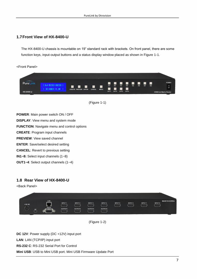
1.9 Front View of HX-4400-U
The HX-4400-U chassis is mountable on 19” standard rack with brackets. On front panel, there are some
function keys, input-output buttons and a status display window placed as shown in Figure 1-1.
<Front Panel>
(Figure 1-1)
POWER: Main power switch ON / OFF
DISPLAY: View menu and system mode
FUNCTION: Navigate menu and control options
CREATE: Program input channels
PREVIEW: View saved channel
ENTER: Save/select desired setting
CANCEL: Revert to previous setting
IN1~4: Select input channels (1~4)
OUT1~4: Select output channels (1~4)
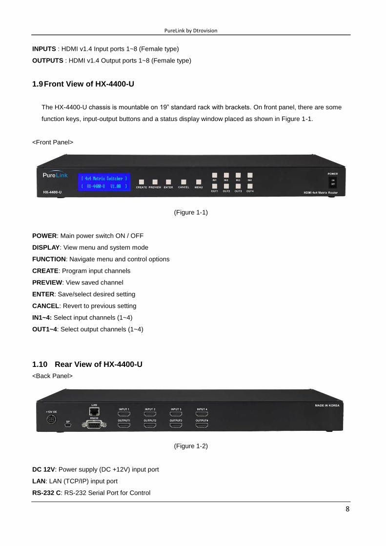
1.10 Rear View of HX-4400-U
<Back Panel>
(Figure 1-2)
DC 12V: Power supply (DC +12V) input port
LAN: LAN (TCP/IP) input port
RS-232 C: RS-232 Serial Port for Control
PureLink by Dtrovision
9
Mini USB: USB to Mini USB port. Mini USB Firmware Update Port
INPUTS : HDMI v1.4 Input ports 1~4 (Female type)
OUTPUTS : HDMI v1.4 Output ports 1~4 (Female type)
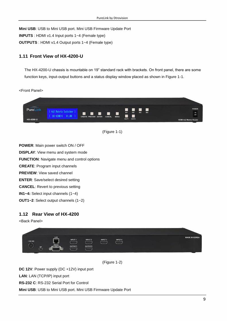
1.11 Front View of HX-4200-U
The HX-4200-U chassis is mountable on 19” standard rack with brackets. On front panel, there are some
function keys, input-output buttons and a status display window placed as shown in Figure 1-1.
<Front Panel>
(Figure 1-1)
POWER: Main power switch ON / OFF
DISPLAY: View menu and system mode
FUNCTION: Navigate menu and control options
CREATE: Program input channels
PREVIEW: View saved channel
ENTER: Save/select desired setting
CANCEL: Revert to previous setting
IN1~4: Select input channels (1~4)
OUT1~2: Select output channels (1~2)
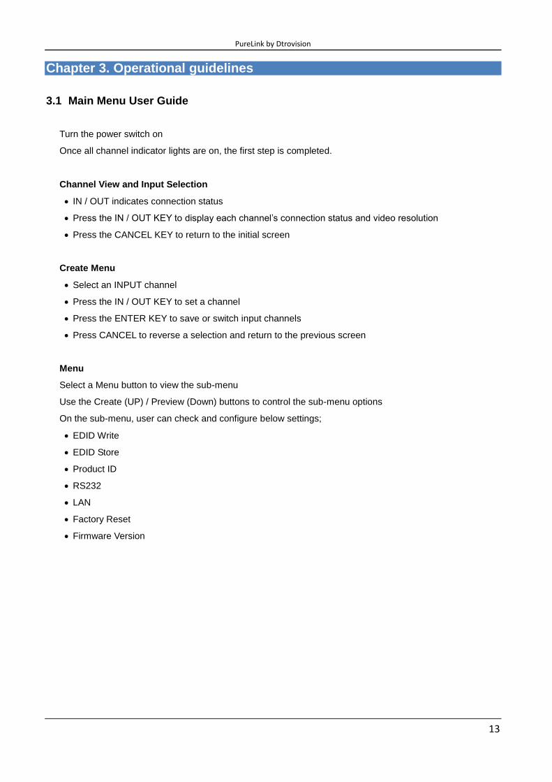
1.12 Rear View of HX-4200
<Back Panel>
(Figure 1-2)
DC 12V: Power supply (DC +12V) input port
LAN: LAN (TCP/IP) input port
RS-232 C: RS-232 Serial Port for Control
Mini USB: USB to Mini USB port. Mini USB Firmware Update Port

PureLink by Dtrovision
10
INPUTS : HDMI v1.4 Input ports 1~4 (Female type)
OUTPUTS : HDMI v1.4 Output ports 1~2 (Female type)

PureLink by Dtrovision
11
1.13 Installation Guidelines
The following installation settings are recommended for optimal performance.
Operational temperature should be 30° C or below
Operational humidity should be 60% or below
Operational environment should be dust-free and well ventilated
Stabilized AC input power (AVR-based power supply) is highly advised

PureLink by Dtrovision
12
Chapter 2. Product Features
HX series Matrix Router receives signals from HDMI output ports or equipment compliant up to HDMI Ver. 1.4,
and sends them to multiple displays.
Compliant to HDMI v1.4, the next generation standard for A/V
19” standard rack type case (1U)
Imbedded monitor distribution function for all output channels
Enhanced quality and color of digital signals
External EDID read function, supports HDMI or DVI displays.
Supporting Function
Supports high resolution up to UHD (4K2K)
PC Resolution up to 1920 x 1200 @ 60Hz
HDTV Resolution up to Ultra HD 4K
4096 x 2160 @24/25/30Hz
(RGB/YCbCr 4:4:4 8 bits, YCbCr 4:2:2 8/10/12 bits)
4096 x 2160 @50/60Hz (YCbCr 4:2:0 8 bits)
Control through 4 different method
- Select directly with front push buttons
- Control method through RS-232C COM port
- Select by LAN (TCP/IP): optional
It has an instantaneous noise protection circuit in input and output ports; therefore it can protect
expensive equipment from fault caused by noises (if any).
Convenient to change firmware through direct update by PC.
PureLink by Dtrovision
13
Chapter 3. Operational guidelines
3.1 Main Menu User Guide
Turn the power switch on
Once all channel indicator lights are on, the first step is completed.
Channel View and Input Selection
IN / OUT indicates connection status
Press the IN / OUT KEY to display each channel’s connection status and video resolution
Press the CANCEL KEY to return to the initial screen
Create Menu
Select an INPUT channel
Press the IN / OUT KEY to set a channel
Press the ENTER KEY to save or switch input channels
Press CANCEL to reverse a selection and return to the previous screen
Menu
Select a Menu button to view the sub-menu
Use the Create (UP) / Preview (Down) buttons to control the sub-menu options
On the sub-menu, user can check and configure below settings;
EDID Write
EDID Store
Product ID
RS232
LAN
Factory Reset
Firmware Version

PureLink by Dtrovision
14
EDID Burn
i) Int EDID Burn
- On this menu, select an EDID from the library and save it on to the Input EEPROM. HX series
Matrix Router has 14 selectable most widely used EDID data pre-programmed and 6 empty slots that
can be used to upload and save EDID data from any external display device.
Select Internal EDID using UP (Create) and Down (Preview) buttons
Select Input# where selected EDID data will be saved on to. Multiple Inputs can be selected at
once.
Push enter button to save
* “P” will display on the LCD when EDID is successfully saved, “F” will display on the
LCD when EDID is NOT successfully saved.
ii) Ext EDID Burn
- This menu is to emulate EDID data from any display devices that are connected to the
Matrix Router's Output via copper cables and save it on to Matrix Router's Input EEPROM.
Select Output #
Selected Output's display device's EDID information will be displayed
Select Input# where selected EDID data will be saved on to. Multiple Input can be selected at
once.
Push enter button to save.
* “P” will display on the LCD when EDID is successfully saved, “F” will display on the
LCD when EDID is NOT successfully saved.
EDID Store
- On this menu, user can emulate EDID data from any display devices that are
connected to Matrix Router's Output via copper cables and save it on to the EDID library
for future use.
Select Output #
Selected Output's display device's EDID information will be displayed
Select empty slot on EDID library where selected EDID data will be saved on to.
Push enter button to save.
* “P” will display on the LCD when EDID is successfully saved, “F” will display on the LCD when EDID
is NOT successfully saved.
Router ID
- By setting different ID to the Matrix Router, up to 255 units of HX series Matrix Router can be
connected and operated in the same network either via serial or LAN communication. Router ID can be
set between 001 ~ 255.
* Factory default setting is 001
PureLink by Dtrovision
15
Note) Router ID is associated with commend control Protocol; therefore, it is important to remember
Matrix Router's current Router ID.
RS232
- There are four values those need to be set for serial communication; baud rate, data bits, stop bits,
and parity. Click and select each value using touch screen and push enter button to save.
Factory default (recommended) settings for serial communication are:
Baud rate - 19200
Data bits - 8
Parity - none
Stop bits - 1
Flow control – none
and supported settings are:
Supported Baud Rate: 4800 Bps, 9600 Bps, 14400 Bps, 19200 Bps, 38400 Bps,
57600Bps, 76800 Bps, 115200 Bps
Supported Data bit: 5 bit, 6 bit, 7 bit, 8 bit
Supported Parity: Non, Even, Odd
Supported Stop bit: 1 bit, 2 bit
LAN
- HX series Matrix Router can be controlled through the 10/100 base Ethernet port using a command
line interface.
There are four values that need to be set for LAN communication; IP address, Gateway address,
Subnet mask, and Mac address. Please use below button indication to configure LAN settings;
(For HX-8800-U, HX-8400-U, HX-8200-U):
* Input #1 : 1 * Output #1 : 9
* Input #2 : 2 * Output #2 : 0
* Input #3 : 3
* Input #4 : 4
* Input #5 : 5
* Input #6 : 6
* Input #7 : 7
* Input #8 : 8
PureLink by Dtrovision
16
(For HX-4400-U, HX-4200-U):
* Input #1 : 1st set (1
st set.xxx.xxx.xxx) * Output #1 : To move cursor left
* Input #2 : 2nd
set (xxx.2nd
set.xxx.xxx) * Output #2 : To move cursor right
* Input #3 : 3rd
set (xxx.xxx.3rd
set.xxx) * Create button: Numbers going up
* Input #4 : 4th
set (xxx.xxx.xxx.4th
set) * Preview button: Numbers going down
Please use Enter button to save the setting
Note) Please contact your Network Administrator for network information to avoid any IP conflict.
Factory default settings for LAN communication are:
IP Address: 192.168.000.002
Gateway Address: 192.168.000.001
Subnet Mask: 255.255.255.000
Mac Address: Matrix Router has its own MAC address and that MAC address allows user to
communicate with PC network solutions without any communication conflict.
**How to change the LAN IP address setting using the front panel key of the matrix switcher for HX-4200:
1. Go to front of the switcher.
2. Press the ‘Menu’ button
3. Use the ‘Create’ and ‘Preview’ buttons to shift up and down
4. Choose ‘5. Lan’ and press Enter button
5. Choose ‘1. IP Address’ and press Enter button
6. Now you have the IP Address shown on the screen
7. The cursor will be located on the first set of numbers of the default IP Address
8. Use the ‘Create’ and ‘Preview’ button to change numbers
9. a. To go from left and right, use ‘Out1’ and ‘Out2’ buttons
b. To change numbers up and down, use ‘Create’ and ‘Preview’ buttons
c. To move to the second set of numbers on the ip address, Press ‘In2’ button
d. To the third set of numbers on the IP address, Press ’In3’ button
f. To the fourth set of numbers on the IP address, Press ‘In4’ button to move
(Note: Data will not go higher than 255 for any of the column or it will show error screen if you go higher)
10. After configuring to the correct IP Address, press Enter button
**Use same method to change Gateway, Subnet Mask IP Address.

PureLink by Dtrovision
17
Factory Reset
Factory reset will put the general setting back to the factory default mode.
Factory default setting value:
RS-232 Baud rate: 19200 Bps
IP Address: 192.168.000.002
Gateway: 192.168.000.001
Input/output Connection: No Connection
Product ID: 255
All Video/Audio switching connection becomes clear
Serial communication setting will be restored back to the factory default
Baud Rate: 19200, Data Bits: 8, Parity: None, Stop Bits: 1
LAN Communication setting will be restored back to the factory default
IP Address: 192.168.000.002
Gateway Address: 192.168.000.001
Subnet Mask: 255.255.255.000
Firmware Version
- Matrix Router’s firmware version can be checked using Up/Down buttons

PureLink by Dtrovision
18
Chapter 4. Communication Code Configuration
4.1 Control Programmer’s Guide (Code Structure and Examples)
This section is designed for programmers who wish to create their own control programs using the
command code. All PureLink digital matrix routers provide a simple character stream control used by
external control devices attached to a PureLink device. Command codes are used primarily for
control, during system installation and setup, and for diagnostic purposes.
4.2 Overview
Command code is a set of alphanumeric characters that combine to form control commands.
Command code strings are entered into a terminal emulation program (such as windows
HyperTerminal) running on an external control device. The control device (PC, third-party controller)
sends the commands to the system. Control devices must be able to send and receive ASCII or
HEXA code via an RS-232 or Ethernet port.
4.3 Command Code Formats
A command code is a series of command characters and numbers used to send commands to the
system. Commands include basic formulas for creating and disconnecting switches, as well as for
verifying the status of switches.
In a command code, each character is either general command (e.g., C for connect) or an identifier that
indicates what the following number designates (e.g., “O” and the number following it designate an “output
number”). The command code *255CI01O01! Can be interested as follows: (*) Starting the command code
(255) Router ID is 255 (C) Create connection on (I01) Input 01 to (O01) Output 01 (!) take the command. For a
complete list of command characters and their functions, see pages 16 -
Ack value (Acknowledge value: Response from Pure Link device) will be echoed back to the terminal screen
as the unit accepts them. When a command is successfully executed, all of the characters appear containing
the character “s” which stands for status. For example,
Ex 1) Command (Connect Input 1 to Output 1)
*255CI01O01!
Ack value
*255sC I01O01!
Ex 2) Command (Check Input connection status on Output 3)
*255?O03!
Ack Value
*255s? I03O03!

PureLink by Dtrovision
19
4.4 General Rules for Command Codes
The commands are coded in ASCII and HEXA. Please refer to Table 3.1 on pg. 16 for detailed
descriptions of keys and functions. A basic command code setup is shown below;
Ex) *255CI01O01!
Start (*) + Router ID (255) + Command (C) + Input number (I01) + Output
number (O01) + End (!) + Enter ( )
▶ A command line allows execution of only one command. Multiple commands require execution of
multiple strings; one command per string.
▶ All s begin with * (Start) byte.
▶ All s end with ! (End) byte.
▶ All s will be executed when (Enter) is entered.
▶ The correct Router ID must be entered in a command code. Systems will not
react to the command if a wrong Router ID is entered. The Factory Default
Router ID is set to 255 and the universal Router ID is 999. Systems will react
to the command whenever universal Router ID is entered in command code.
▶ Command codes typically are not case-sensitive.
▶ *Audio Command is only available for MXA series product*
▶ To specify multiple inputs and outputs, enter a “,” (Comma) between numbers.
(Ex., *255CI01O01,02,03! : Connects Input 01 to Output 01, 02, and 03)
▶ Use - (Hyphen) for range connection.
(EX., *255CI01O01-04! : Connects Input 01 to Output 01,02,03, and 04)

PureLink by Dtrovision
20
Table 3.1 Command Codes Characters Table
The table below shows command code characters (keys), which are used to generate control commands,
their functions, and short function descriptions.
Key Function Description and Example Byte
HEX ASCII
0x2A * Start the command Header Code 1
0x21 ! End the command Tail Code 1
Execute the command Execute the command
0x43
0x63
C
C Connect (Video and Audio)
Initiates a Connect (switch) command for both
Video and Audio; this must precede input and
output specification
1
0x3F ? Status Status command; this must precede input and
output specification 1
0x44
0x64
D
D Disconnect
Disconnect command for both Video and Audio;
this must precede input and output specification 1
, Space Separates the numbers within entries that
contain multiple numbers 1
- Range Specifies a range of numbers in entries
containing multiple numbers 1
0x49
0x69
I
I Router ID check
Router ID check command; check router’s
current ID number 1
?version Firmware version check Firmware version check command;
*255?version!
0x4E
0x6E
N
N Networking setting
Network configuration setting command:
- IP Setting
*255NIP125.135.199.004!
- Subnet Mask Setting
*255NSM255.255.255.000!
- Gate Way Setting
*255NGW192.168.000.001!
- MAC Address Setting
*255NMA00.50.C2.B0.20.05!
- Port Number Setting
*255NPN3000!
- Network Information
*255NNI000!
1
0x48
0x68
H
H Connection check
Router communication connection check
command: *255H000! 1
PureLink by Dtrovision
21
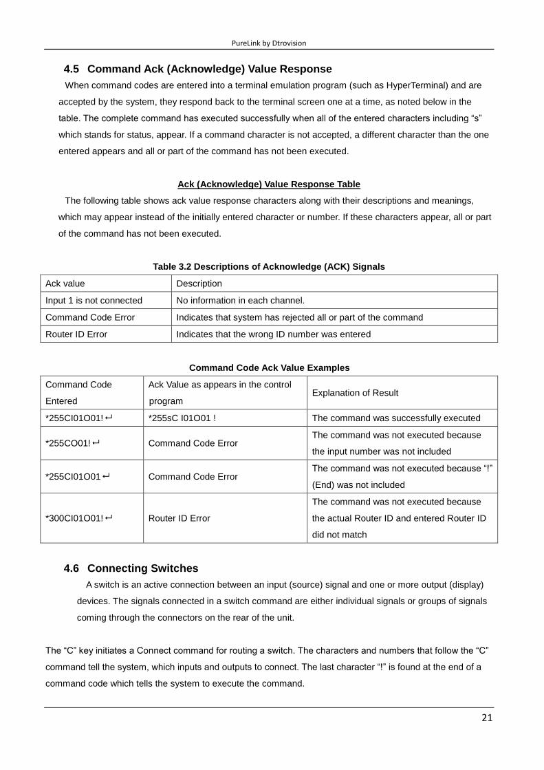
4.5 Command Ack (Acknowledge) Value Response
When command codes are entered into a terminal emulation program (such as HyperTerminal) and are
accepted by the system, they respond back to the terminal screen one at a time, as noted below in the
table. The complete command has executed successfully when all of the entered characters including “s”
which stands for status, appear. If a command character is not accepted, a different character than the one
entered appears and all or part of the command has not been executed.
Ack (Acknowledge) Value Response Table
The following table shows ack value response characters along with their descriptions and meanings,
which may appear instead of the initially entered character or number. If these characters appear, all or part
of the command has not been executed.
Table 3.2 Descriptions of Acknowledge (ACK) Signals
Ack value Description
Input 1 is not connected No information in each channel.
Command Code Error Indicates that system has rejected all or part of the command
Router ID Error Indicates that the wrong ID number was entered
Command Code Ack Value Examples
Command Code
Entered
Ack Value as appears in the control
program Explanation of Result
*255CI01O01! *255sC I01O01 ! The command was successfully executed
*255CO01! Command Code Error The command was not executed because
the input number was not included
*255CI01O01 Command Code Error The command was not executed because “!”
(End) was not included
*300CI01O01! Router ID Error
The command was not executed because
the actual Router ID and entered Router ID
did not match
4.6 Connecting Switches
A switch is an active connection between an input (source) signal and one or more output (display)
devices. The signals connected in a switch command are either individual signals or groups of signals
coming through the connectors on the rear of the unit.
The “C” key initiates a Connect command for routing a switch. The characters and numbers that follow the “C”
command tell the system, which inputs and outputs to connect. The last character “!” is found at the end of a
command code which tells the system to execute the command.
PureLink by Dtrovision
22
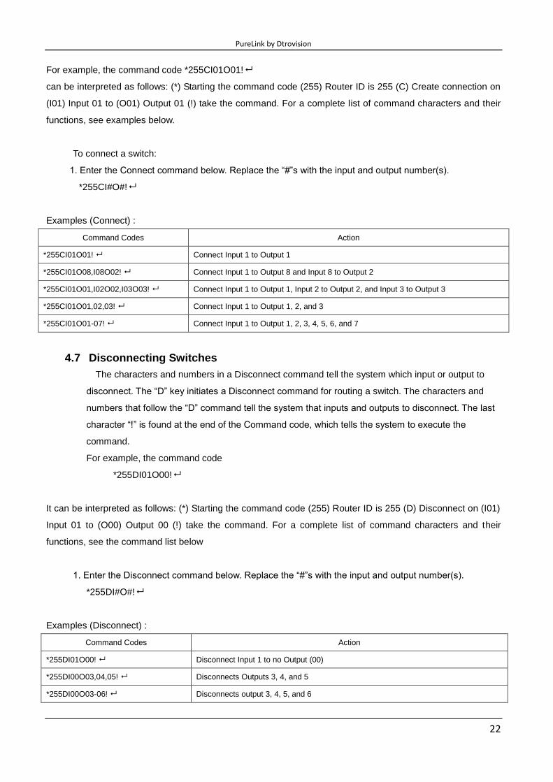
For example, the command code *255CI01O01!
can be interpreted as follows: (*) Starting the command code (255) Router ID is 255 (C) Create connection on
(I01) Input 01 to (O01) Output 01 (!) take the command. For a complete list of command characters and their
functions, see examples below.
To connect a switch:
1. Enter the Connect command below. Replace the “#”s with the input and output number(s).
*255CI#O#!
Examples (Connect) :
Command Codes Action
*255CI01O01! Connect Input 1 to Output 1
*255CI01O08,I08O02! Connect Input 1 to Output 8 and Input 8 to Output 2
*255CI01O01,I02O02,I03O03! Connect Input 1 to Output 1, Input 2 to Output 2, and Input 3 to Output 3
*255CI01O01,02,03! Connect Input 1 to Output 1, 2, and 3
*255CI01O01-07! Connect Input 1 to Output 1, 2, 3, 4, 5, 6, and 7
4.7 Disconnecting Switches
The characters and numbers in a Disconnect command tell the system which input or output to
disconnect. The “D” key initiates a Disconnect command for routing a switch. The characters and
numbers that follow the “D” command tell the system that inputs and outputs to disconnect. The last
character “!” is found at the end of the Command code, which tells the system to execute the
command.
For example, the command code
*255DI01O00!
It can be interpreted as follows: (*) Starting the command code (255) Router ID is 255 (D) Disconnect on (I01)
Input 01 to (O00) Output 00 (!) take the command. For a complete list of command characters and their
functions, see the command list below
1. Enter the Disconnect command below. Replace the “#”s with the input and output number(s).
*255DI#O#!
Examples (Disconnect) :
Command Codes Action
*255DI01O00! Disconnect Input 1 to no Output (00)
*255DI00O03,04,05! Disconnects Outputs 3, 4, and 5
*255DI00O03-06! Disconnects output 3, 4, 5, and 6

PureLink by Dtrovision
23
*255DALLIO! Disconnects all inputs and outputs
4.8 Connection Status Check
A connection status can be checked to confirm that the switch has been correctly executed or to
confirm correct routing to multiple outputs. The characters and numbers in a status command tell the
system which input or output to check.
1. Enter the Connection status check command below. Replace the “#”s with the input and output
number(s).
*255?I#! or *255?O#!
Examples:
Command Codes Action
*255?I01! Check Output connection status on Input 1
*255?O07! Check Input connection status on Output 7
*255?ALLIO! Check all Input and Output connection status
Router ID Check
User can confirm the router’s Current ID setting: Universal Router ID is 999
Example:
Command Codes Action
*999I000! Check Router’s ID
Firmware Version Check
User can confirm router’s current firmware version.
Example:
Command Codes Action
*999?version! Check Router’s Firmware version
Baud Rate Setting
Network Configuration: User can check and set network configuration for LAN control.
Examples:
Command Codes Action
*255NNI000! Check current Network Information
*255NIP192.168.000.004! Set IP address at 125.135.199.004
*255NSM255.255.255.000! Set Subnet Mask at 255.255.255.000
*255NGW192.168.000.001! Set Gate Way at 192.168.000.001

PureLink by Dtrovision
24
*255NMA00.00.C2.B0.20.05! Set Mac Address at 00.00.C2.B0.20.05
*255NPN3000! Set Port Number at 3000
Connection Checking: User can check the connection status.
Example:
Command Codes Action
*255H000! Check connection status
Function Key On/Off:
User can enable or disable the function key located on physical router’s front panel.
Example:
Command Codes Action
*255K000! Function key On/Off

PureLink by Dtrovision
25
4.9 LAN CODE CONFIGURATION
Using TELNET protocol with LAN(TCP/IP)
The HX series Matrix Router can be controlled from remote locations through the LAN port using
WINDOWS XP DOS prompts, hyper-terminal, or TELNET program (the control code is fully compliant
with RS-232C).
Enter TELNET <Router IP
Address> in the DOS
prompt
Message indicating
TELNET connection will
appear
Router ID verification
command code
Send “ *255I000! ”
Router will send response:
“ *255sI Router ID 255”
*255I000! *255sI Router ID 255*
PureLink by Dtrovision
26
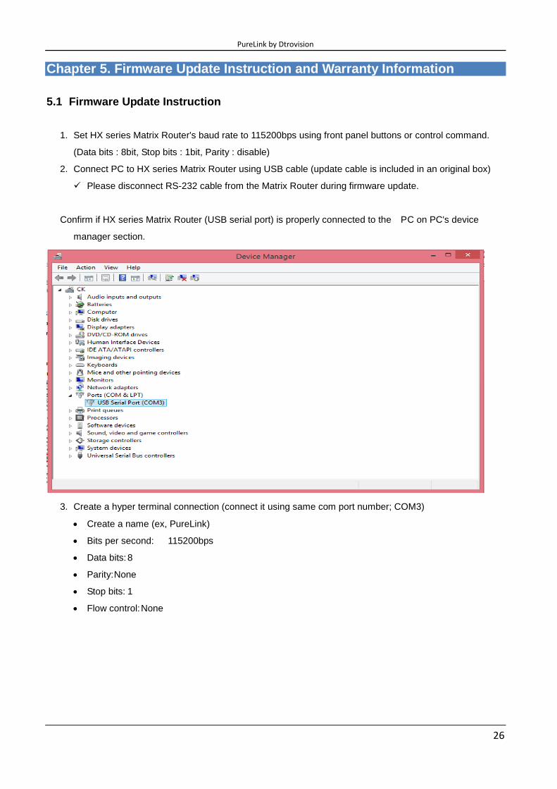
Chapter 5. Firmware Update Instruction and Warranty Information
5.1 Firmware Update Instruction
1. Set HX series Matrix Router's baud rate to 115200bps using front panel buttons or control command.
(Data bits : 8bit, Stop bits : 1bit, Parity : disable)
2. Connect PC to HX series Matrix Router using USB cable (update cable is included in an original box)
Please disconnect RS-232 cable from the Matrix Router during firmware update.
Confirm if HX series Matrix Router (USB serial port) is properly connected to the PC on PC's device
manager section.
3. Create a hyper terminal connection (connect it using same com port number; COM3)
Create a name (ex, PureLink)
Bits per second: 115200bps
Data bits: 8
Parity: None
Stop bits: 1
Flow control: None

PureLink by Dtrovision
27
4. Hyper terminal setting
Go to file --> Properties

PureLink by Dtrovision
28
5. Go to Settings --> Click the ASCII Setup
6. Check box - Echo typed characters locally

PureLink by Dtrovision
29
7. Press OK
8. Type " program " and then Enter
PureLink by Dtrovision
30
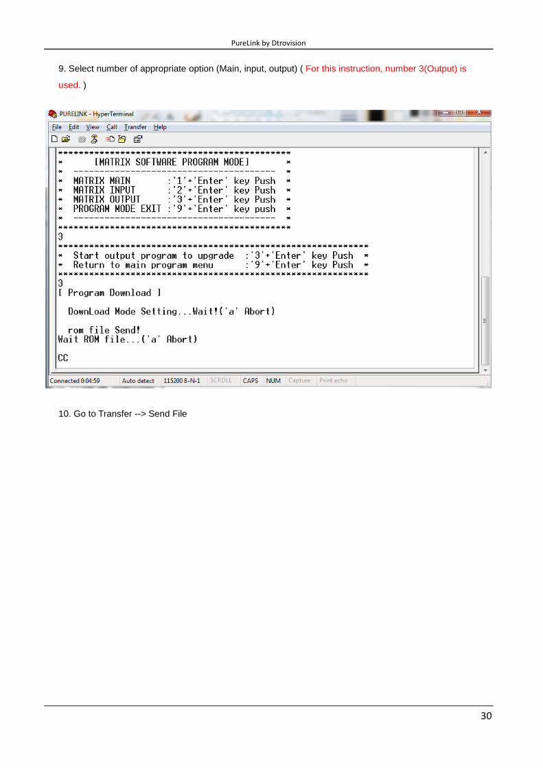
9. Select number of appropriate option (Main, input, output) ( For this instruction, number 3(Output) is
used. )
10. Go to Transfer --> Send File

PureLink by Dtrovision
31
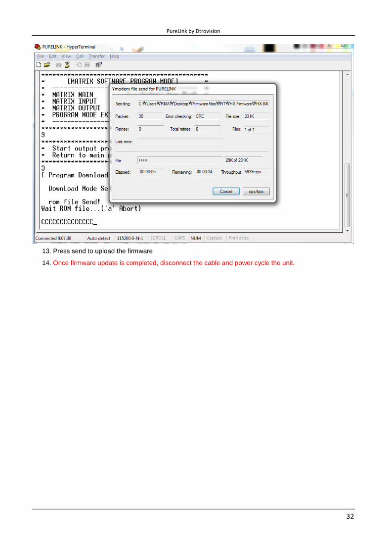
11. Browse and select proper firmware file.
12. Select Ymodem
PureLink by Dtrovision
32
13. Press send to upload the firmware
14. Once firmware update is completed, disconnect the cable and power cycle the unit.

PureLink by Dtrovision
33
Chapter 6. Additional Information
6.1 Manufacturer’s Warranty (2-Year)
Dtrovision warrants this HX Series HDMI Integrated Matrix Router to be free from defects in workmanship
and materials, under normal use and service, for a period of two (2) year from the date of purchase from
Dtrovision or its authorized resellers.
If the product does not operate as warranted during the applicable warranty period,
Dtrovision shall, at its option and expense, execute one of the following as necessary:
1. Repair the defective product or part
2. Deliver to customer and equivalent product or part to replace the defective item
3. Refund to customer the purchase price paid for the defective product
All products that are replaced become the property of Dtrovision, LLC. Replacement
products may be new or reconditioned. Repaired or replacement products or parts
come with a 90-day warranty or the remainder of the warranty period. Dtrovision shall
not be responsible for any software, firmware, information, or memory data loss of
contained in, stored on, or integrated with any products returned to Dtrovision for repair
under warranty.
6.2 Customer Service
Any customer service inquiries can be submitted electronically through the Q&A form on our website
( www.purelinkav.com ).
For immediate assistance please contact us at (201) 488-3232 to reach our customer care or tech support
team.