DVI Computer Sharing Device CS261 / CS261TK
48
DVI Computer Sharing Device CS261 / CS261TK User Manual www.aten.com
Transcript of DVI Computer Sharing Device CS261 / CS261TK
DVI Computer Sharing Device
CS261 / CS261TKUser Manual
www.aten.com

CS261 / CS261TK User Manual
EMC Information
FEDERAL COMMUNICATIONS COMMISSION INTERFERENCE STATEMENT: This equipment has been tested and found to comply with the limits for a Class A digital device, pursuant to Part 15 of the FCC Rules. These limits are designed to provide reasonable protection against harmful interference when the equipment is operated in a commercial environment. This equipment generates, uses, and can radiate radio frequency energy and, if not installed and used in accordance with the instruction manual, may cause harmful interference to radio communications. Operation of this equipment in a residential area is likely to cause harmful interference in which case the user will be required to correct the interference at his own expense.
The device complies with Part 15 of the FCC Rules. Operation is subject to the following two conditions: (1) this device may not cause harmful interference, and (2) this device must accept any interference received, including interference that may cause undesired operation.
FCC Caution: Any changes or modifications not expressly approved by the party responsible for compliance could void the user's authority to operate this equipment.
Warning: Operation of this equipment in a residential environment could cause radio interference. Achtung: Der Gebrauch dieses Geräts in Wohnumgebung kann Funkstörungen verursachen.
KCC Statement
RoHS
This product is RoHS compliant.
ii

CS261 / CS261TK User Manual
User Information
Online RegistrationBe sure to register your product at our online support center:
Telephone SupportFor telephone support, call this number:
User NoticeAll information, documentation, and specifications contained in this manual are subject to change without prior notification by the manufacturer. The manufacturer makes no representations or warranties, either expressed or implied, with respect to the contents hereof and specifically disclaims any warranties as to merchantability or fitness for any particular purpose. Any of the manufacturer's software described in this manual is sold or licensed `as is'. Should the programs prove defective following their purchase, the buyer (and not the manufacturer, its distributor, or its dealer), assumes the entire cost of all necessary servicing, repair and any incidental or consequential damages resulting from any defect in the software.
The manufacturer of this system is not responsible for any radio and/or TV interference caused by unauthorized modifications to this device. It is the responsibility of the user to correct such interference.
The manufacturer is not responsible for any damage incurred in the operation of this system if the correct operational voltage setting was not selected prior to operation. PLEASE VERIFY THAT THE VOLTAGE SETTING IS CORRECT BEFORE USE.
International http://eservice.aten.com
International 886-2-8692-6959
China 86-400-810-0-810
Japan 81-3-5615-5811
Korea 82-2-467-6789
North America 1-888-999-ATEN ext 49881-949-428-1111
iii

CS261 / CS261TK User Manual
Package Contents
1 CS261 / CS261TK 2-Port DVI Computer Sharing Device
1 custom KVM cable set (1.8m)
1 power adapter
1 user instructions*
Note: 1. * Features may have been added to the KVM over IP console station since the user instructions were created. Please visit our website to download the most up-to-date version of the user manual.
2. Make sure that all of the components are present and in good order. If anything is missing or was damaged in shipping, contact your dealer.
3. Read this manual thoroughly and follow the installation and operation procedures carefully to prevent any damage to the unit, and/or any of the devices connected to it.
iv

CS261 / CS261TK User Manual
ContentsEMC Information . . . . . . . . . . . . . . . . . . . . . . . . . . . . . . . . . . . . . . . . . . . . iiRoHS. . . . . . . . . . . . . . . . . . . . . . . . . . . . . . . . . . . . . . . . . . . . . . . . . . . . . . iiUser Information . . . . . . . . . . . . . . . . . . . . . . . . . . . . . . . . . . . . . . . . . . . . .iii
Online Registration . . . . . . . . . . . . . . . . . . . . . . . . . . . . . . . . . . . . . . . .iiiTelephone Support . . . . . . . . . . . . . . . . . . . . . . . . . . . . . . . . . . . . . . . .iiiUser Notice . . . . . . . . . . . . . . . . . . . . . . . . . . . . . . . . . . . . . . . . . . . . . .iii
Package Contents . . . . . . . . . . . . . . . . . . . . . . . . . . . . . . . . . . . . . . . . . . ivAbout this Manual . . . . . . . . . . . . . . . . . . . . . . . . . . . . . . . . . . . . . . . . . . viiConventions . . . . . . . . . . . . . . . . . . . . . . . . . . . . . . . . . . . . . . . . . . . . . . .viiiProduct Information. . . . . . . . . . . . . . . . . . . . . . . . . . . . . . . . . . . . . . . . . .viii
1. IntroductionOverview . . . . . . . . . . . . . . . . . . . . . . . . . . . . . . . . . . . . . . . . . . . . . . . . . . . 1Features . . . . . . . . . . . . . . . . . . . . . . . . . . . . . . . . . . . . . . . . . . . . . . . . . . . 2Requirements . . . . . . . . . . . . . . . . . . . . . . . . . . . . . . . . . . . . . . . . . . . . . . . 4
Console . . . . . . . . . . . . . . . . . . . . . . . . . . . . . . . . . . . . . . . . . . . . . . . . 4Computer . . . . . . . . . . . . . . . . . . . . . . . . . . . . . . . . . . . . . . . . . . . . . . . 4Cables . . . . . . . . . . . . . . . . . . . . . . . . . . . . . . . . . . . . . . . . . . . . . . . . . 4
KVM Cables. . . . . . . . . . . . . . . . . . . . . . . . . . . . . . . . . . . . . . . . . . . 4Video Interface Converters . . . . . . . . . . . . . . . . . . . . . . . . . . . . . . . 4
Operating Systems . . . . . . . . . . . . . . . . . . . . . . . . . . . . . . . . . . . . . . . . 5Components . . . . . . . . . . . . . . . . . . . . . . . . . . . . . . . . . . . . . . . . . . . . . . . . 6
CS261 / CS261TK Front Panel . . . . . . . . . . . . . . . . . . . . . . . . . . . . . . 6CS261 / CS261TK Rear Panel . . . . . . . . . . . . . . . . . . . . . . . . . . . . . . . 7(Optional) 2XRT-0015G KVM over IP Access Control Box. . . . . . . . . . 8
2. Hardware SetupInstallation. . . . . . . . . . . . . . . . . . . . . . . . . . . . . . . . . . . . . . . . . . . . . . . . . . 9
Installation Diagram. . . . . . . . . . . . . . . . . . . . . . . . . . . . . . . . . . . . . . . 10
3. Basic OperationOverview . . . . . . . . . . . . . . . . . . . . . . . . . . . . . . . . . . . . . . . . . . . . . . . . . . 11Pushbutton Console Mode Selection . . . . . . . . . . . . . . . . . . . . . . . . . . . . 11Hotkey Console Mode Selection . . . . . . . . . . . . . . . . . . . . . . . . . . . . . . . . 112XRT-0015G KVM over IP Access Control Box . . . . . . . . . . . . . . . . . . . 12
LED statuses . . . . . . . . . . . . . . . . . . . . . . . . . . . . . . . . . . . . . . . . . . . . 12
4. OperationOverview . . . . . . . . . . . . . . . . . . . . . . . . . . . . . . . . . . . . . . . . . . . . . . . . . . 13Auto Mode. . . . . . . . . . . . . . . . . . . . . . . . . . . . . . . . . . . . . . . . . . . . . . . . . 13
Private Mode (Console 1) . . . . . . . . . . . . . . . . . . . . . . . . . . . . . . . . . . 14Screen Saver. . . . . . . . . . . . . . . . . . . . . . . . . . . . . . . . . . . . . . . . . . . . 15DIP Switch Settings Table. . . . . . . . . . . . . . . . . . . . . . . . . . . . . . . . . . 15
v

CS261 / CS261TK User Manual
Manual Mode . . . . . . . . . . . . . . . . . . . . . . . . . . . . . . . . . . . . . . . . . . . . . . 16Timeout . . . . . . . . . . . . . . . . . . . . . . . . . . . . . . . . . . . . . . . . . . . . . . . . 17Multiple EDID Selection . . . . . . . . . . . . . . . . . . . . . . . . . . . . . . . . . . . 17
Invoke Hotkey Settings Mode . . . . . . . . . . . . . . . . . . . . . . . . . . . . . . . . . 18Hotkey Settings Mode Summary Table. . . . . . . . . . . . . . . . . . . . . . . . 19
Keyboard Emulation . . . . . . . . . . . . . . . . . . . . . . . . . . . . . . . . . . . . . . . . 21
5. The Firmware Upgrade UtilityIntroduction . . . . . . . . . . . . . . . . . . . . . . . . . . . . . . . . . . . . . . . . . . . . . . . . 23
Downloading the Firmware Upgrade Package . . . . . . . . . . . . . . . . . . 23Preparation . . . . . . . . . . . . . . . . . . . . . . . . . . . . . . . . . . . . . . . . . . . . . . . 24Starting the Upgrade . . . . . . . . . . . . . . . . . . . . . . . . . . . . . . . . . . . . . . . . 25Upgrade Succeeded . . . . . . . . . . . . . . . . . . . . . . . . . . . . . . . . . . . . . . . . 27Upgrade Failed . . . . . . . . . . . . . . . . . . . . . . . . . . . . . . . . . . . . . . . . . . . . . 27Firmware Upgrade Recovery . . . . . . . . . . . . . . . . . . . . . . . . . . . . . . . . . . 28
6. AppendixSafety Instructions . . . . . . . . . . . . . . . . . . . . . . . . . . . . . . . . . . . . . . . . . . 29
General . . . . . . . . . . . . . . . . . . . . . . . . . . . . . . . . . . . . . . . . . . . . . . . 29Technical Support . . . . . . . . . . . . . . . . . . . . . . . . . . . . . . . . . . . . . . . . . . 31
International . . . . . . . . . . . . . . . . . . . . . . . . . . . . . . . . . . . . . . . . . . . . 31North America . . . . . . . . . . . . . . . . . . . . . . . . . . . . . . . . . . . . . . . . . . 31
Specifications . . . . . . . . . . . . . . . . . . . . . . . . . . . . . . . . . . . . . . . . . . . . . . 32CS261 / CS261TK Factory Default Settings . . . . . . . . . . . . . . . . . . . . . . 33Operation Modes . . . . . . . . . . . . . . . . . . . . . . . . . . . . . . . . . . . . . . . . . . . 34Troubleshooting . . . . . . . . . . . . . . . . . . . . . . . . . . . . . . . . . . . . . . . . . . . . 36Limited Warranty. . . . . . . . . . . . . . . . . . . . . . . . . . . . . . . . . . . . . . . . . . . . 37
vi

CS261 / CS261TK User Manual
About this Manual
This User Manual is provided to help you get the most from your CS261 / CS261TK. It covers all aspects of installation, configuration and operation. An overview of the information found in the manual is provided below.
Chapter 1, Introduction, introduces you to the CS261 / CS261TK system. Its purpose, features and benefits are presented, and its front and back panel components are described.
Chapter 2, Hardware Setup, describes how to set up your installation. The necessary steps, from basic to advanced setups, are provided.
Chapter 3, Basic Operation, explains the fundamental concepts involved in operating the CS261 / CS261TK.
Chapter 4, Operation, explains the CS261 / CS261TK’s operating and hotkey settings mode as well as the EDID selection feature.
Chapter 5, The Firmware Upgrade Utility, explains how to use this utility to upgrade the CS261 / CS261TK firmware to the latest available version.
An Appendix, provides specifications and other technical information regarding the CS261 / CS261TK.
Note:
Read this manual thoroughly and follow the installation and operation procedures carefully to prevent any damage to the unit or any connected devices.
ATEN regularly updates its product documentation for new features and fixes. For an up-to-date CS261 / CS261TK documentation, visit ......................... http://www.aten.com/global/en/
vii

CS261 / CS261TK User Manual
Conventions
This manual uses the following conventions:
Product InformationFor information about all ATEN products and how they can help you connect without limits, visit ATEN on the Web or contact an ATEN Authorized Reseller. Visit ATEN on the Web for a list of locations and telephone numbers:
Monospaced Indicates text that you should key in.
[ ] Indicates keys you should press. For example, [Enter] means to press the Enter key. If keys need to be chorded, they appear together in the same bracket with a plus sign between them: [Ctrl+Alt].
1. Numbered lists represent procedures with sequential steps.
♦ Bullet lists provide information, but do not involve sequential steps.
> Indicates selecting the option (on a menu or dialog box, for example), that comes next. For example, Start > Run means to open the Start menu, and then select Run.
Indicates critical information.
International http://www.aten.com
North America http://www.aten-usa.com
viii
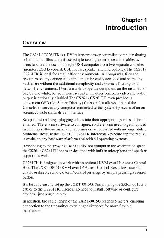
Chapter 1Introduction
Overview
The CS261 / CS261TK is a DVI micro-processor controlled computer sharing solution that offers a multi-user/single-tasking experience and enables two users to share the use of a single USB computer from two separate consoles (monitor, USB keyboard, USB mouse, speaker and microphone). The CS261 / CS261TK is ideal for small office environments. All programs, files and resources on any connected computer can be easily accessed and shared by both users without the additional complexity and expense of setting up a network environment. Users are able to operate computers on the installation one by one while, for additional security, the other console's video and audio output is optionally disabled.The CS261 / CS261TK even provides a convenient OSD (On Screen Display) function that allows either of the Consoles to access any computer connected to the system by means of an on screen, console status driven interface.
Setup is fast and easy; plugging cables into their appropriate ports is all that is entailed. There is no software to configure, so there is no need to get involved in complex software installation routines or be concerned with incompatibility problems. Because the CS261 / CS261TK intercepts keyboard input directly, it works on any hardware platform and with all operating systems.
Responding to the growing use of audio input/output in the workstation space, the CS261 / CS261TK has been designed with built in microphone and speaker support, as well.
CS261TK is designed to work with an optional KVM over IP Access Control Box. The 2XRT-0015G KVM over IP Access Control Box allows users to enable or disable remote over IP control privilege by simply pressing a control button.
It’s fast and easy to set up the 2XRT-0015G. Simply plug the 2XRT-0015G’s cables to the CS261TK. There is no need to install software or configure devices - just plug and play,.
In addition, the cable length of the 2XRT-0015G reaches 5 meters, enabling connection to the transmitter over longer distances for more flexible installation.
1
CS261 / CS261TK User Manual
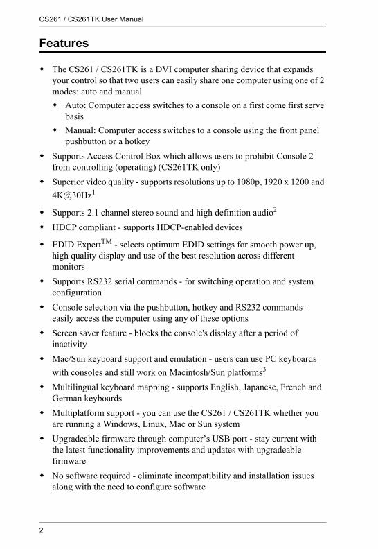
Features
The CS261 / CS261TK is a DVI computer sharing device that expands your control so that two users can easily share one computer using one of 2 modes: auto and manual Auto: Computer access switches to a console on a first come first serve
basis Manual: Computer access switches to a console using the front panel
pushbutton or a hotkey Supports Access Control Box which allows users to prohibit Console 2
from controlling (operating) (CS261TK only) Superior video quality - supports resolutions up to 1080p, 1920 x 1200 and
4K@30Hz1
Supports 2.1 channel stereo sound and high definition audio2
HDCP compliant - supports HDCP-enabled devices
EDID ExpertTM - selects optimum EDID settings for smooth power up, high quality display and use of the best resolution across different monitors
Supports RS232 serial commands - for switching operation and system configuration
Console selection via the pushbutton, hotkey and RS232 commands - easily access the computer using any of these options
Screen saver feature - blocks the console's display after a period of inactivity
Mac/Sun keyboard support and emulation - users can use PC keyboards with consoles and still work on Macintosh/Sun platforms3
Multilingual keyboard mapping - supports English, Japanese, French and German keyboards
Multiplatform support - you can use the CS261 / CS261TK whether you are running a Windows, Linux, Mac or Sun system
Upgradeable firmware through computer’s USB port - stay current with the latest functionality improvements and updates with upgradeable firmware
No software required - eliminate incompatibility and installation issues along with the need to configure software
2

1. Introduction
Note: 1. 4K2K@30Hz is supported when using a DVI to HDMI cable.
2. High definition audio can be converted using a DVI to HDMI cable.
3. PC keyboard combinations emulate Mac/Sun keyboards.
3

CS261 / CS261TK User Manual
Requirements
Console A DVI monitor capable of the highest resolution that you will be using on
any computer in the installation A USB Keyboard and a USB Mouse Speakers and microphone (optional)
ComputerThe following equipment must be installed on the computer that is to be connected to the system: A DVI video port USB Type A port Speaker and microphone ports (optional)
CablesUse of substandard cables may damage the connected devices or degrade overall performance. For optimum signal integrity and to simplify the layout, we strongly recommend that you use the following high quality Custom Cable sets:
KVM Cables 2L-7D02U: 1.8m 2L-7D03U: 3.0m 2L-7D05U: 5.0m
Video Interface Converters 2A-127G: DVI to HDMI 2A-128G: HDMI to DVI
4

1. Introduction
Operating SystemsSupported operating systems are shown in the table below:
OS Version
Windows 2000 and higher
Linux RedHat 6.0 and higher
SuSE 8.2 and higher
UNIX FreeBSD 3.51 and higher
Sun Solaris 8 and higher
Novell Netware 5.0 and higher
Mac OS 9 and higher
5

CS261 / CS261TK User Manual
Components
CS261 / CS261TK Front Panel
* In Auto Mode, when neither console is accessing the computer, both Console LEDs are illuminated.
No. Component Description
1 MANUAL/AUTOselection pushbutton
This pushbutton is used to switch between Manual and Auto Modes. The default is Auto Mode. Repeatedly pressing the button cycles through the modes in the following order: Auto Mode -> Console 1 (Manual) -> Console 2 (Manual) -> Auto Mode.
2 C1 LED* Lights when Console 1 accesses the computer. Turns off when Console 2 accesses the computer.
3 C2 LED* Lights when Console 2 accesses the computer. Turns off when Console 1 accesses the computer.
4 MANUAL LED Lights to indicate that the CS261 / CS261TK is set to Manual Mode. In Auto Mode the LED does not illuminate.
6
1. Introduction
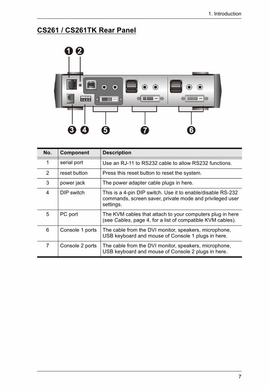
CS261 / CS261TK Rear Panel
No. Component Description
1 serial port Use an RJ-11 to RS232 cable to allow RS232 functions.
2 reset button Press this reset button to reset the system.
3 power jack The power adapter cable plugs in here.
4 DIP switch This is a 4-pin DIP switch. Use it to enable/disable RS-232 commands, screen saver, private mode and privileged user settings.
5 PC port The KVM cables that attach to your computers plug in here (see Cables, page 4, for a list of compatible KVM cables).
6 Console 1 ports The cable from the DVI monitor, speakers, microphone, USB keyboard and mouse of Console 1 plugs in here.
7 Console 2 ports The cable from the DVI monitor, speakers, microphone, USB keyboard and mouse of Console 2 plugs in here.
7

CS261 / CS261TK User Manual
(Optional) 2XRT-0015G KVM over IP Access Control Box
Note: The 2XRT-0015G KVM over IP Access Control Box is an optional accessory designed for CS261TK only.
No. Component Description Indication
1 control button / LED Press the button to enable or disable remote over IP control access.
Lights red
2 USB connector Connects to a USB port to power on the device.
3 PS/2 connector Connects to the PS/2 port for control access.
4 RJ-11 connector Connects to the RJ-11 port for control access.
5 RJ-232 connector Connects to the RS-232 port for control access.
4 235
1
8
Chapter 2Hardware Setup
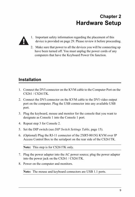
Installation
1. Connect the DVI connector on the KVM cable to the Computer Port on the CS261 / CS261TK.
2. Connect the DVI connector on the KVM cable to the DVI video output port on the computer. Plug the USB connector into any available USB port.
3. Plug the keyboard, mouse and monitor for the console that you want to designate as Console 1 into the Console 1 port.
4. Repeat step 3 for Console 2.
5. Set the DIP switch (see DIP Switch Settings Table, page 15).
6. (Optional) Plug the RJ-11 connector of the 2XRT-0015G KVM over IP Access Control Box to the serialport on the rear side of the CS261TK.
Note: This step is for CS261TK only.
7. Plug the power adapter into the AC power source; plug the power adapter into the power jack on the CS261 / CS261TK.
8. Power on the computer and monitors.
Note: The mouse and keyboard connectors are USB 1.1 ports.
1. Important safety information regarding the placement of this device is provided on page 29. Please review it before proceeding.
2. Make sure that power to all the devices you will be connecting up have been turned off. You must unplug the power cords of any computers that have the Keyboard Power On function.
9

CS261 / CS261TK User Manual
Installation Diagram
10

Chapter 3Basic Operation
Overview
As a computer sharing device, the CS261 / CS261TK provides basic access via two different console modes: Console 1 Mode and Console 2 Mode. The CS261 / CS261TK provides three convenient methods of selecting console modes: Pushbutton Console Mode Selection – press the pushbutton on the front panel, Hotkey Console Mode Selection – enter combinations from the keyboard, and RS232 Serial Control – send RS232 commands.*
Note: Please refer to the CS261 / CS261TK RS232 Command User Manual for further details.
For CS261TK that is designed to work with the 2XRT-0015G KVM over IP Access Control Box. The 2XRT-0015G KVM over IP Access Control Box allows users to enable or disable remote over IP control privilege by simply pressing a control button.
Pushbutton Console Mode Selection
Press the pushbutton on the front panel repeatedly to bring the focus to the desired console mode as follows:
Auto Mode → Manual Mode (Console 1) → Manual Mode (Console 2) → Auto Mode.
The LED lights indicate that the console is accessing the computer.
Hotkey Console Mode Selection
Selecting console modes via hotkey works only within Manual Mode (Console 1 and Console 2 mode). Press the [Scroll Lock] key twice and then the [Enter] key to switch from Console 1 to Console 2.
Note: If using [Scroll Lock] conflicts with other programs, [Ctrl] can be used instead, e.g. [Ctrl] [Ctrl] [Enter].
11

CS261 / CS261TK User Manual
2XRT-0015G KVM over IP Access Control Box
This optional 2XRT-0015G KVM over IP Access Control Box is a control button accessory to enable / disable remote KVM over IP access.
LED statuses
Button Status LED Function
Pressed Red Light Disable remote access
Released Dim Enable remote access
12
Chapter 4Operation
Overview
The CS261 / CS261TK features two operation modes: Auto Mode and Manual Mode. For a brief overview of these modes, see Operation Modes, page 34.
Auto Mode
For general, low-priority scenarios, default Auto Mode offers the simplest usability for computer sharing where control of the computer is selected on a first come, first served basis.
Auto Mode operates according to the following rules:
1. When the CS261 / CS261TK is turned on it starts in Auto Mode, and operates on a first come, first served basis. Both Console LEDs are On; the Manual LED is Off.
2. The first user to strike the keyboard or move the mouse gains control of the computer. As soon as this occurs: The Console LED that corresponds to the user's console turns On. The Console LED for the other console turns Off. The CS261 / CS261TK locks onto that user's console. If the user uses the keyboard or moves the mouse, a message appears
on the other user’s monitor indicating that the system is in use. After 10 seconds, the message will disappear and the user can view the computer display again (if the other user stops using the keyboard and moving the mouse). When the other user uses the keyboard or moves the mouse again, the OSD message will reappear:
The System Is Occupied. Please Wait. The user who has control of the computer can prevent the other user
from viewing the computer display and listening to the audio output by entering the following Hotkey combination:
[Num Lock]+[-],[D]If the other user uses the keyboard or moves the mouse, a message appears indicating that the system is in use. After 10 seconds, the message disappears and the monitor displays a black background. If the
13

CS261 / CS261TK User Manual
user uses the keyboard or moves the mouse, the OSD message will reappear.
3. If the user who has access to the CS261 / CS261TK does not use the keyboard or move the mouse before the Timeout Period (set with hotkeys) elapses: The CS261 / CS261TK unlocks from that user's console; Then, the CS261 / CS261TK switches to Auto Mode; Both Console LEDs turn On; The Manual LED is Off (since the CS261 / CS261TK is in Auto
Mode); Either console may take control of the computer.
4. To terminate Auto Mode access, repeatedly press the MANUAL/AUTO Button until the desired console controls the device.
Private Mode (Console 1)For high-priority scenarios, Private Mode offers the best control during computer sharing where a specific user can at any time take control of the system. Console 1 or Console 2 can be set as the privileged user by setting the DIP switch pin four on or off (see page 15), which can also prevent the non-privileged user from viewing and controlling the computer (see page 13). Private Mode operates within Auto Mode and does not include a Timeout Period.
To enter Private Mode:
1. Make sure that the device is in Auto Mode and that DIP switch pin 3 is set to the On position before powering on the CS261 / CS261TK.
2. Set Console 1 user as the privileged user if DIP switch pin 4 is set to On position. Otherwise, Console 2 user will be the privileged user.
3. Power on the CS261 / CS261TK.
4. Wait for the Timeout period to expire (default: 5s).
5. From the keyboard of the privileged user, press the Shift key six times within two seconds.In Private Mode, the user who does not have control of the computer (i.e. not the privileged user) cannot view or hear the computer. As a result, the OSD warning message does not appear in Private Mode.
To exit Private Mode:
14

Chapter 4. Operation
From the keyboard of the privileged user, press the Shift key six times within 2 seconds.
Or Press the MANUAL/AUTO Button.
Screen SaverTo protect the screens, when the CS261 / CS261TK is in Auto Mode or Manual Mode and no one is accessing the computer, both monitors will display a black background. If one of the consoles accesses the computer, the black background screen will disappear. To enable this function, set DIP switch pin 2 to the On position.
DIP Switch Settings Table
Note: 1. Press a DIP switch pin down to turn it on and up to turn it off.
2. For best results, set the DIP switch pin before turning on both the CS261 / CS261TK or the computer.
DIP Switch Pins Function
1 2 3 4
On X X X RS232 Command Function Enabled
Off X X X RS232 Command Function Disabled
X On X X Screen Saver Enabled
X Off X X Screen Saver Disabled
X X On On Private Mode Enabled: Console 1 is the Privileged User
X X On Off Private Mode Enabled: Console 2 is the Privileged User
X X Off On Private Mode Disabled
X X Off Off Private Mode Disabled
15

CS261 / CS261TK User Manual
Manual Mode
For longer tasks where uninterrupted access to the computer is required, Manual Mode offers the best operation setting for computer sharing. It is invoked by repeatedly pressing the MANUAL/AUTO Button to bring the focus to the desired console as follows:
Auto Mode → Manual Mode (Console 1) → Manual Mode (Console 2) → Auto Mode
When Manual Mode is invoked, the CS261 / CS261TK switches to the selected console and prohibits the other console from controlling the computer. The selected console retains control until the MANUAL/AUTO Button is pressed again.
A message appears on the other user’s monitor indicating that the system is in use. After 10 seconds, the message disappears and the user can view the computer display. If the user strikes the keyboard or moves the mouse, the OSD message is displayed again:
The System Is Occupied. Please Wait. The user who has control of the computer can prevent the other user from
viewing the computer display and listening the computer’s audio output by entering the following Hotkey combination:
[Num Lock]+[-],[D]If the other user strikes the keyboard or moves the mouse, a message appears indicating that the system is in use. After 10 seconds, the message disappears and the monitor displays a black background. If the user strikes the keyboard or moves the mouse, the OSD message is displayed again.
To switch access to the computer between the two consoles: Press the Manual/Auto Mode Button, or Enter the following hotkey combination:
[Scroll Lock], [Scroll Lock], [Enter]
Note: 1. This hotkey combination is for CS261 only.
2. If using the Scroll Lock key conflicts with other programs running on the computer, the Ctrl key can be used instead, e.g. [Ctrl][Ctrl][Enter]
16

Chapter 4. Operation
TimeoutIn Auto Mode, users can set timeout period by hotkeys. Please refer to the see Hotkey Settings Mode Summary Table, page 19, for hotkey parameters that correspond to Timeout lengths (see Auto Mode, page 13, for more information). The Timeout Period cannot be applied in Manual Mode and Private Mode.
Multiple EDID SelectionUsers can select from Remix mode, Port1 mode and ATEN Default EDID mode, and from three resolutions. Multiple EDID selection can help improve video quality.
Users can select a desired EDID mode via Hotkeys (see Hotkey Settings Mode Summary Table, page 19, for more details).
17

CS261 / CS261TK User Manual
Invoke Hotkey Settings Mode
To invoke HSM, please complete the following steps:
1. Press and hold down the Num Lock key.
2. Press and release the minus [-] key.
3. Release the Num Lock key.
Note: 1. The minus key must be released within half a second, otherwise the Hotkey invocation will be canceled.
2. There is an alternate key combination to invoke the HSM. Please see Hotkey Settings Mode Summary Table, page 19, for more details.
18

Chapter 4. Operation
Hotkey Settings Mode Summary Table
Combination Function
[Num Lock] + [-]
[H] Toggles between the default [Num Lock] [-] and alternate [Ctrl][F12] HSM invocation keys.
[T] Toggles between the default [Scroll Lock] [Scroll Lock] and alternate [Ctrl][Ctrl] port switching keys.
[B] Enables/Disables buzzer.
[R] [Enter] Resets the hotkey settings to their default status.
[D] Turn the other console's monitor and audio off or on. (This setting applies until changed or until CS261 / CS261TK is powered off.)
[O] [N] [Enter] In Auto Mode, determines the amount of time that passes from the last input by the controlling console to when the console lock is released. N=1: 5 second timeoutN=2: 60 second timeoutN=3: 120 second timeoutN=4: 255 second timeout
[S] [N] [Enter] Determine the amount of time that passes from the last input by the controlling console to when screen saver appears. N=1: 1 minuteN=2: 5 minutesN=3: 10 minutesN=4: 15 minutesN=5: 20 minutes
[E] [N] [Enter] Set EDID mode. (N=1, 2, 3, 4, 5)N=1: Set Remix Mode.N=2: Set Port1 Mode.N=3: Set ATEN default EDID, 1280x720@60HzN=4: Set ATEN default EDID, 1600x1200@60HzN=5: Set ATEN default EDID, 1920x1080@60Hz
[F1] Sets the PC keyboard layout.
[F2] Enables Mac keyboard emulation.
[F3] Enables Sun keyboard emulation.
19

CS261 / CS261TK User Manual
[Num Lock] + [-]
[F4] Lists the current hotkey settings via the Paste function of a text editor.E.g. Hotkey: [num lock]+[-] and [scroll lock], [scroll lock] OS setting: PC Keyboard emulation: Enabled Mouse emulation: Enabled Keyboard layout: English
[F5] Performs a USB keyboard and mouse reset.
[F6] [NN] [Enter] Set the keyboard language layout. Where “NN” is two digital numbers that represents the keyboard language code: U.S. English: 33 Japanese: 15 French: 08 German: 09
[u][p][g][r][a][d][e] [Enter]
Invokes the Firmware Upgrade Mode.
[Esc] or [Space Bar] Exits Hotkey Settings Mode.
Combination Function
20

Chapter 4. Operation
Keyboard Emulation
Note: When using key combinations, press and release the first key (Ctrl), then press and release the activation key.
PC Keyboard Mac Keyboard PC Keyboard Sun Keyboard
[Shift] Shift [Ctrl] [T] Stop
[Ctrl] Ctrl [Ctrl] [F2] Again
[Ctrl] [F3] Props
[Ctrl] [1] [Ctrl] [F4] Undo
[Ctrl] [2] [Ctrl] [F5] Front
[Ctrl] [3] [Ctrl] [F6] Copy
[Ctrl] [4] [Ctrl] [F7] Open
[Alt] Alt [Ctrl] [F8] Paste
[Print Screen] F13 [Ctrl] [F9] Find
[Scroll Lock] F14 [Ctrl] [F10] Cut
= [Ctrl] [1]
[Enter] Return [Ctrl] [2]
[Backspace] Delete [Ctrl] [3]
[Insert] Help [Ctrl] [4]
[Ctrl] F15 [Ctrl] [H] Help
Compose
-
+
21

CS261 / CS261TK User Manual
This Page Intentionally Left Blank
22

Chapter 5The Firmware Upgrade Utility
Introduction
The purpose of the Windows-based Firmware Upgrade Utility is to provide an automated process for upgrading all CS261 / CS261TK switches in an installation. The program comes as part of a Firmware Upgrade Package that is specific for each device.
As new firmware versions become available, new firmware upgrade packages are posted on our website. Check the website regularly to find the latest information and packages.
Downloading the Firmware Upgrade PackageTo download the firmware upgrade package:
1. that is not part of your KVM installation, go to our website (www.aten.com) and choose the model name of your device. A list of available firmware upgrade packages will appear.
2. Choose the firmware upgrade package that you wish to install (usually the most recent) and download it to your computer.
23

CS261 / CS261TK User Manual
Preparation
To prepare for the firmware upgrade, do the following:
1. Use the KVM Cable Set provided with this unit to connect a USB port on your computer to the USB Type-B port from the PC Port section of your switch.
2. Shut down all the computers on the KVM installation.
3. The CS261 / CS261TK now enters Firmware Upgrade Mode. The two Ports LEDs flash together to indicate that the unit is in Firmware Upgrade Mode.
Note: While the CS261 / CS261TK is in Firmware Upgrade Mode, normal keyboard and mouse functions are suspended. You must complete the firmware upgrade or exit Firmware Upgrade Mode to regain normal control of the console.
24

Chapter 5. The Firmware Upgrade Utility
Starting the Upgrade
To upgrade the firmware:
1. Run the downloaded firmware upgrade package file by double-clicking the file icon.The Firmware Upgrade Utility welcome screen appears:
Note: The screens shown in this section are for reference only. The wording and layout of the actual screens put up by the Firmware Upgrade Utility may vary slightly from these examples.
2. Read and Agree to the License Agreement (enable the I Agree radio button).
3. Click Next to continue. The Firmware Upgrade Utility main screen appears. The devices capable of being upgraded are listed in the Device List panel:
25

CS261 / CS261TK User Manual
4. Select your device. Its description appears in the Device Description panel. Click Next to perform the upgrade.If you enabled Check Firmware Version, the Utility compares the device’s firmware with that of the upgrade file’s. If it finds that the device’s firmware is newer than the upgrade or equal to it, it brings up the dialog box informing you of this and gives you the option to Continue or Cancel.
If you did not enable Check Firmware Version, the Utility installs the upgrade files without checking whether or not they are newer.
As the upgrade proceeds, status messages appear in the Status Messages panel, and the progress toward completion is shown on the Progress bar.
26
Chapter 5. The Firmware Upgrade Utility
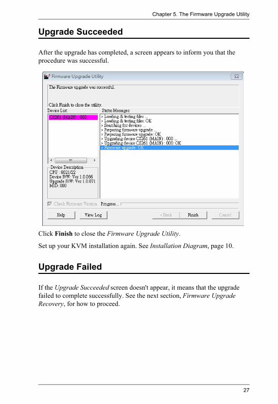
Upgrade Succeeded
After the upgrade has completed, a screen appears to inform you that the procedure was successful.
Click Finish to close the Firmware Upgrade Utility.
Set up your KVM installation again. See Installation Diagram, page 10.
Upgrade Failed
If the Upgrade Succeeded screen doesn't appear, it means that the upgrade failed to complete successfully. See the next section, Firmware Upgrade Recovery, for how to proceed.
27

CS261 / CS261TK User Manual
Firmware Upgrade Recovery
There are three conditions that call for firmware upgrade recovery: When a firmware upgrade is manually aborted. When the mainboard firmware upgrade fails. When the I/O firmware upgrade fails.
To perform a firmware upgrade recovery, do the following:
1. Disconnect the USB connectors on the KVM cables from the computer.
2. Power on the CS261 / CS261TK. It will now work with the original firmware.
28

Appendix
Safety Instructions
General Read all of these instructions. Save them for future reference. Follow all warnings and instructions marked on the device. Do not place the device on any unstable surface (cart, stand, etc.). If the
device falls, serious damage will result. Do not use the device near water. Do not place the device near, or over, radiators or heat registers. The device cabinet is provided with slots and openings to allow for
adequate ventilation. To ensure reliable operation, and to protect against overheating, these openings must never be blocked or covered.
The device should never be placed on a soft surface (bed, sofa, rug, etc.) as this will block its ventilation openings. Likewise, the device should not be placed in a built in enclosure unless adequate ventilation has been provided.
Never spill liquid of any kind on the device. Unplug the device from the wall outlet before cleaning. Do not use liquid
or aerosol cleaners. Use a damp cloth for cleaning. The device should be operated from the type of power source indicated on
the marking label. If you are not sure of the type of power available, consult your dealer or local power company.
Do not allow anything to rest on the power cord or cables. Route the power cord and cables so that they cannot be stepped on or tripped over.
Position system cables and power cables carefully; Be sure that nothing rests on any cables.
When connecting or disconnecting power to hot-pluggable power supplies, observe the following guidelines: Install the power supply before connecting the power cable to the
power supply. Unplug the power cable before removing the power supply. If the system has multiple sources of power, disconnect power from the
system by unplugging all power cables from the power supplies.
29

CS261 / CS261TK User Manual
Never push objects of any kind into or through cabinet slots. They may touch dangerous voltage points or short out parts resulting in a risk of fire or electrical shock.
Do not attempt to service the device yourself. Refer all servicing to qualified service personnel.
If the following conditions occur, unplug the device from the wall outlet and bring it to qualified service personnel for repair. The power cord or plug has become damaged or frayed. Liquid has been spilled into the device. The device has been exposed to rain or water. The device has been dropped, or the cabinet has been damaged. The device exhibits a distinct change in performance, indicating a need
for service. The device does not operate normally when the operating instructions
are followed. Only adjust those controls that are covered in the operating instructions.
Improper adjustment of other controls may result in damage that will require extensive work by a qualified technician to repair.
Do not connect the RJ-11 connector to a public telecommunication network.
30

Appendix
Technical SupportInternational
North America
When you contact us, please have the following information ready beforehand: Product model number, serial number, and date of purchase. Your computer configuration, including operating system, revision level,
expansion cards, and software. Any error messages displayed at the time the error occurred. The sequence of operations that led up to the error. Any other information you feel may be of help.
Email Support Email your questions and concerns to:[email protected]
Online Support Technical Support
Troubleshooting
Documentation
Software Updates
1. Online technical support is available to Altusen cus-tomers through our e-Support Center: http://support.aten.com
2. Online troubleshooting that describes the most com-monly encountered problems and offers possible solu-tions to them; online documentation (including electronically available manuals); and the latest drivers and firmware for your product are available at our web-site: http://www.aten.com
Telephone Support 886-2-8692-6959
Email Support Email your questions and concerns to:[email protected]
Online Support Technical Support
Troubleshooting
Documentation
Software Updates
1. Online technical support is available to Altusen cus-tomers through our e-Support Center: http://www.aten-usa.com/support
2. Online troubleshooting that describes the most com-monly encountered problems and offers possible solu-tions to them; online documentation (including electronically available manuals); and the latest drivers and firmware for your product are available at our web-site: http://www.aten-usa.com
Telephone Support 1-888-999-ATEN
31

CS261 / CS261TK User Manual
Specifications
Function CS261
Computer Connections 1
Console Selection Pushbutton, RS-232, Hotkey
Connectors Console Ports
Keyboard 2 x USB Type A Female
Mouse 2 x USB Type A Female
Video 2 x DVI-D Female (White)
Audio 2 x 3.5mm Audio Jack Female (Green - Speaker)
2 x 3.5mm Audio Jack Female (Pink - Mic)
PC Port Keyboard/Mouse
1 x USB Type B Female
Video 1 x DVI-D Female (White)
Audio 1 x 3.5mm Audio Jack Female (Green - Speaker)
1 x 3.5mm Audio Jack Female (Pink - Mic)
RS-232 1 x RJ-11 Female
Power 1 x DC Jack (Black)
Switches Mode Selection 1 x Pushbutton
Reset 1 x Semi-recessed Pushbutton
DIP 1 x 4 Pin
LEDs Selected 2 (Green)
Manual 1 (Orange)
Video 3840 x 2160 @ 30Hz
Power Consumption DC 5V, 2.4W, 20BTU
Environment Operating Temperature 0–50ºC
Storage Temperature -20–60ºC
Humidity 0–80% RH, Non-condensing
Physical Properties
Housing Metal
Weight 0.72kg (1.59 lb)
Dimensions (L x W x H) 21.00 x 8.80 x 5.55 cm (8.27 x 3.46 x 2.19 in.)
32

Appendix
CS261 / CS261TK Factory Default Settings
Note: Mode Switching with [Scroll Lock] , [Scroll Lock] is for CS261 only.
Setting Default
Mode Selection Auto Mode
Mode Switching [Scroll Lock] , [Scroll Lock]
Invoking HSM [Num Lock] + [-]
Timeout 5 Seconds
Screen Saver 1 minute
EDID Mode Remix Mode
Keyboard Operating Platform PC Compatible
Keyboard Language Layout English
Buzzer Enabled
Firmware Upgrade Mode Disabled
33

CS261 / CS261TK User Manual
Operation Modes
The below table describes the CS261 / CS261TK’s two operation modes and their setting options. Each setting’s active and inactive users’ statuses, as well as details on switching users, are also included.
Note: 1. For more information on selecting a preset console, see DIP Switch Settings Table, page 15.
2. The preset console can be activated and gain exclusive control by pressing the Shift key six times within two seconds.
Operation Mode Setting Active User Inactive User Switching
Auto Mode Default First come, first served
Using the key-board or mouse triggers a mes-sage indicating the system is in use by the privi-
leged user.
Wait for privi-leged user inac-
tivity (default timeout: 5s).
Private Mode First come, first served unless
preset console* activated**
Computer can-not be viewed
and heard.
Preset console can gain exclu-sive control by
pressing the Shift key six times
within two sec-onds. Doing so
again returns the installation to Default Auto
Mode.
Manual Mode
C1 (Console 1) Mode
Console 1 has exclusive access
to the computer***
Using Console 2’s keyboard or
mouse triggers a message indicat-ing the system is in use by Con-
sole 1.
Press Scroll Lock twice to switch to
C2 Mode.
C2 (Console 2) Mode
Console 2 has exclusive access
to the computer***
Using Console 1’s keyboard or
mouse triggers a message indicat-ing the system is in use by Con-
sole 2.
Press Scroll Lock twice to switch to
C1 Mode.
34

Appendix
3. The user with control of the computer can disable display and sound to the other user by using the following hotkey combination: [Num Lock]+[-],[D]
4. The press scroll lock twice to switch to C1 and C2 Mode operation is for CS261 only.
35

CS261 / CS261TK User Manual
Troubleshooting
Note: The symptom cannot switch ports by pressing [Scroll Lock] twice only applies to CS261 only.
Symptom Possible Cause Action
Monitor does not display after the KVM cable set is hot-plugged.
DVI graphics card is not compatible with cable set hot-plugging.
Power off all devices on the installation; power off the CS261 / CS261TK; confirm all KVM cables are properly connected; power on the CS261 / CS261TK; power on the computers.
Graphics card driver is not up-to-date.
Upgrade to the latest graphics card driver.
Mouse and/or keyboard is not responding.
Switch needs to be reset.
Power off all devices on the installation; power off the CS261 / CS261TK; wait five seconds; power on the CS261 / CS261TK again.
Cannot switch ports by pressing [Scroll Lock] twice.
Keyboard is incompatible with [Scroll Lock] invocation.
Switch to the alternate HSM invocation keys. See Hotkey Settings Mode Summary Table, page 19, for details.
36

Appendix
Limited Warranty
ATEN warrants its hardware in the country of purchase against flaws in materials and workmanship for a Warranty Period of two [2] years (warranty period may vary in certain regions/countries) commencing on the date of original purchase. This warranty period includes the LCD panel of ATEN LCD KVM switches. Select products are warranted for an additional year (see A+ Warranty for further details). Cables and accessories are not covered by the Standard Warranty.
What is covered by the Limited Hardware WarrantyATEN will provide a repair service, without charge, during the Warranty Period. If a product is detective, ATEN will, at its discretion, have the option to (1) repair said product with new or repaired components, or (2) replace the entire product with an identical product or with a similar product which fulfills the same function as the defective product. Replaced products assume the warranty of the original product for the remaining period or a period of 90 days, whichever is longer. When the products or components are replaced, the replacing articles shall become customer property and the replaced articles shall become the property of ATEN.
To learn more about our warranty policies, please visit our website:http://www.aten.com/global/en/legal/policies/warranty-policy/
37

CS261 / CS261TK User Manual
MEMO
38

Appendix
MEMO
39

CS261 / CS261TK User Manual
© Copyright 2021 ATEN® International Co., Ltd.
ATEN International Co., Ltd., 3F, No. 125, Sec. 2, Datung Rd., Sijhih District, New Taipei City 221, TaiwanPhone: 886-2-8692-6789 Fax: 886-2-8692-6767 TECHNICAL SUPPORT CENTER: 886-2-8692-6959
: 2021-03-03
ATEN and the ATEN logo are registered trademarks of ATEN International Co., Ltd. All rights reserved.
Manual Part No. PAPE-0370-AT1G
All other brand names and trademarks are the registered property of their respective owners.
Released
40