DUS 1642:2016 UGANDA STANDARD - World Trade Organization · UGANDA STANDARD DUS 1642: 2016 ... (ISO...
40
UGANDA STANDARD DUS 1642:2016 First Edition 2016-03-dd Reference number DUS 1642:2016 © UNBS 2016 Domestic biogas stoves — Specification
Transcript of DUS 1642:2016 UGANDA STANDARD - World Trade Organization · UGANDA STANDARD DUS 1642: 2016 ... (ISO...

UGANDA STANDARD
DUS 1642:2016
First Edition 2016-03-dd
Reference number DUS 1642:2016
© UNBS 2016
Domestic biogas stoves — Specification

DUS 1642: 2016
ii © UNBS 2016 – All rights reserved
Compliance with this standard does not, of itself confer immunity from legal obligations
A Uganda Standard does not purport to include all necessary provisions of a contract. Users are responsible for its correct application
© UNBS 2015
All rights reserved. Unless otherwise specified, no part of this publication may be reproduced or utilised in any form or by any means, electronic or mechanical, including photocopying and microfilm, without prior written permission from UNBS.
Requests for permission to reproduce this document should be addressed to
The Executive Director Uganda National Bureau of Standards P.O. Box 6329 Kampala Uganda Tel: 256 414 505 995 Fax: 256 414 286 123 E-mail: [email protected]
Web: www.unbs.go.ug
DUS 1642:2016
© UNBS 2016 – All rights reserved iii
Contents Page
Foreword .......................................................................................................................................................v
1 Scope ................................................................................................................................................1
2 Normative references .......................................................................................................................1
3 Terms and definitions ......................................................................................................................1 3.1 Definitions ........................................................................................................................................1 3.2. Abbreviation ....................................................................................................................................2
4 General and construction requirements .........................................................................................2 4.1 General requirements ......................................................................................................................2 4.2 Materials ...........................................................................................................................................2 4.3 Design for maintenance ...................................................................................................................3 4.4 Rigidity and stability ........................................................................................................................4 4.5 Gas taps ............................................................................................................................................4 4.6 Finishes ............................................................................................................................................6 4.7 Electroplated body ...........................................................................................................................6 4.7.2 Adhesion test ...................................................................................................................................7 4.7.3 Corrosion resistance test.................................................................................................................7 4.8 Paints or similar finishes .................................................................................................................7 4.9 Concealed gas supplies ...................................................................................................................9 4.10 Screws, nuts, bolts and springs ......................................................................................................9 4.11 Injector jets .......................................................................................................................................9 4.12 Burners .............................................................................................................................................9 4.13 Pan support .................................................................................................................................... 10 4.14 Gas inlet connections .................................................................................................................... 10 4.15 Gas soundness............................................................................................................................... 11 4.16 Strength test ................................................................................................................................... 11
5 Performance ................................................................................................................................... 11 5.2 Gas consumption. .......................................................................................................................... 11 5.3 Ignition and flame travel ................................................................................................................ 12 5.3.2 Electric ignition performance test, if applicable ........................................................................... 12 5.4 Flame stability ................................................................................................................................ 12 5.4.3 Wind resistance .............................................................................................................................. 12 5.4.4 Test for combustion stability ......................................................................................................... 12 5.4.5 Pilot flame performance ................................................................................................................. 12 5.5 Noise control .................................................................................................................................. 12 5.6 Formation of soot ........................................................................................................................... 13 5.7 Flashback ....................................................................................................................................... 13 5.8 Combustion .................................................................................................................................... 13 5.9 Surface temperature ....................................................................................................................... 13 5.10 Thermal efficiency .......................................................................................................................... 13 5.11 Ignition rate and performance of an electric igniter ..................................................................... 14 5.12 Durability ........................................................................................................................................ 14 5.13 Classification of tests..................................................................................................................... 14 5.13.1 Type tests ....................................................................................................................................... 14 5.13.3 Routine tests .................................................................................................................................. 15
8 Process quality assurance control ................................................................................................ 15 8.1 General ........................................................................................................................................... 15 9.2 Raw materials ................................................................................................................................. 15 6.3 Dimension ....................................................................................................................................... 15 6.4 Machining ....................................................................................................................................... 15
DUS 1642: 2016
iv © UNBS 2016 – All rights reserved
6.7 Welding ........................................................................................................................................... 15 6.8 Quality plan .................................................................................................................................... 15
7 Instructions .................................................................................................................................... 16
8 Marking ........................................................................................................................................... 16
9 Packing ........................................................................................................................................... 16
10 Sampling ......................................................................................................................................... 16 10.1 Batch ...................................................................................................... Error! Bookmark not defined. 10.2 Lot .......................................................................................................... Error! Bookmark not defined. 10.3 Defective sample ................................................................................... Error! Bookmark not defined. 10.4 Random sampling .......................................................................................................................... 17 10.5 Sampling plan for visual inspection and dimensional check: ..................................................... 17 10.5.2 Criteria for conformity .................................................................................................................... 17 10.6 Supervision inspection .................................................................................................................. 17 10.6.2 Disqualification item classification and determination methods ................................................. 17
Annex A (normative) Method of test for plastic components .................................................................. 19 A.1 Method ............................................................................................................................................ 19
Annex B (normative) Method for flash back test for materials of burners .............................................. 20 B.1 Procedure ....................................................................................................................................... 20
Annex C (normative) Test appropriate to vitreous enamelled components ......................................... 21 C.1 All enamelled components shall pass the tests given in C.1.1 and C.1.2. .................................. 21 C.1.1 Citric acid spot test ........................................................................................................................ 21 C.1.1.2 Reagents ......................................................................................................................................... 21 C.1.1.3 Test procedure ............................................................................................................................... 21 C.1.2 Impact resistance test .................................................................................................................... 22 C.1.2.1 Apparatus ....................................................................................................................................... 22 C.1.2.2 Procedure ....................................................................................................................................... 22 C.2 Thermal shock resistance test ...................................................................................................... 23 C.2.1.1 Test procedure ............................................................................................................................... 23
Annex D (normative) Method of test for gas soundness ........................................................................ 24 D.1 Procedure ....................................................................................................................................... 24
Annex E (normative) Strength test .......................................................................................................... 25 E.1 Procedure ....................................................................................................................................... 25
Annex F (normative) Gas consumption and thermal efficiency test ..................................................... 26 F.1 General ........................................................................................................................................... 26 F.2 Procedure ....................................................................................................................................... 26
Annex G (normative) Method for determination of carbon monoxide ................................................... 28 G.1 Procedure ....................................................................................................................................... 28
Annex H (Informative) Biogas Combustion ............................................................................................ 29 H.1 Combustion .................................................................................................................................... 29
Bibliography................................................................................................................................................ 30
DUS 1642:2016
© UNBS 2016 – All rights reserved v
Foreword
Uganda National Bureau of Standards (UNBS) is a parastatal under the Ministry of Trade, Industry and Cooperatives established under Cap 327, of the Laws of Uganda, as amended. UNBS is mandated to co-ordinate the elaboration of standards and is
(a) a member of International Organisation for Standardisation (ISO) and
(b) a contact point for the WHO/FAO Codex Alimentarius Commission on Food Standards, and
(c) the National Enquiry Point on TBT Agreement of the World Trade Organisation (WTO).
The work of preparing Uganda Standards is carried out through Technical Committees. A Technical Committee is established to deliberate on standards in a given field or area and consists of representatives of consumers, traders, academicians, manufacturers, government and other stakeholders.
Draft Uganda Standards adopted by the Technical Committee are widely circulated to stakeholders and the general public for comments. The committee reviews the comments before recommending the draft standards for approval and declaration as Uganda Standards by the National Standards Council.
Responsible Technical Committee

DUS 1642: 2016
vi © UNBS 2016 – All rights reserved
UGANDA STANDARD DUS 1642: 2016
© UNBS 2016 – All rights reserved 1
Domestic biogas stoves — Specification
1 Scope
This Uganda Standard covers construction, operation, safety requirements and methods of test for stoves intended for use with domestic biogas systems.
2 Normative references
The following referenced documents are indispensable for the application of this document. For dated references, only the edition cited applies. For undated references, the latest edition of the referenced document (including any amendments) applies.
US EAS 123, Distilled water — Specification
ISO 8458-1, Steel wire for mechanical springs — Part 1: General requirements
ISO 6361, Wrought aluminium and aluminium alloy sheets, strips and plates
ISO 1463, Metallic and oxide coatings — Measurement of coating thickness — Microscopical method
ISO 2177, Metallic coatings — Measurement of coating thickness — Coulometric method by anodic dissolution
ISO/TR 11728, Anodized aluminium and aluminium alloys — Accelerated test of weather fastness of coloured anodic oxide coatings using cyclic artificial light and pollution gas
ISO 16151, Corrosion of metals and alloys — Accelerated cyclic tests with exposure to acidified salt spray, "dry" and "wet" conditions
ISO 7-1, Pipe threads where pressure-tight joints are made on the threads — Part 1: Dimensions, tolerances and designation
CD/ENG/ 12:2012, Biogas — Glossary, abbreviations and fundamental principles
3 Terms and definitions
3.1 Definitions
For the purposes of this Uganda Standard the following definitions given in CD/ENG/ 12:2012 shall apply.
10.1 Batch
All of the products made from one source of raw material and made at the same time shall constitute a batch.
2 © UNBS 2016 – All rights reserved
10.2 Lot
A number of products offered for inspection at one time and manufactured from the raw material from same source shall constitute a lot. Maximum and recommended lot size shall be 500 sets of Biogas Stoves.
10.3 Defective sample
Any sample not conforming to any one or more of the specified requirements.
3.2. Abbreviation
For the purposes of this Uganda Standard abbreviation given in DUS 1641 shall apply
4 General and construction requirements
4.1 General requirements
4.1.1 Construction of all parts of the equipment shall be sound and of high standard of workmanship and appropriate finish. The appearance of biogas stove shall be free of obvious scratch or any other appearance defect. Construction shall ensure durability and shall comply with the safety requirements.
4.1.2 Rivets, fastening screws, plugs, etc, shall not lead into gas passages except where adequate provisions have been made to ensure permanent gas tight joints.
4.1.3 The air-tightness from the biogas entrance to the combustion via a valve shall be such that the leakage is less than 0.7 L/h under a pressure of 4.2 kPa and ignited under a 1.5 times of pressure without leakage. Compliance is confirmed by igniting all the burners under a pressure of 1.5 times of the rated pressure and using leakage testing solution to test the leakage from the plug valve to the burner flame hole.
4.2 Materials
4.2.1 Parts and components of domestic biogas stove may be of cast iron, steel, non-ferrous metal or corrosion resistant material conforming to the applicable national standards. The stove shall be free from swarf, grit and other foreign matters. Wherever possible, rigid metal tubing shall be used for internal gas supplies integral with the stove. If flexible tubing is used, it shall not be fitted on the outlet side of any control which is capable of cutting off the gas completely; except when metal connections are fitted. The use of low pressure plastic tubing fitted or pushed on nozzle is not recommended.
4.2.2. Plastic components, which are liable to heating (for example, tap handles, push buttons, etc) shall be free from fissures, distortion, blemishes and discoloration and shall not show signs of ageing when tested as covered in Annex A.
4.2.3 The material used in the construction of the stove or its parts shall be resistant to wear and deterioration occurring in the normal use and the burner parts shall not melt or distort when the stove burner is operated with flames flashed back for half an hour in the mixing tube. This shall be checked by the test detailed in Annex B.
4.2.4 The nozzles, nozzle holders and liquid containing plates shall be of metal material with the melting
point over 500 °C.
4.2.5 Burners and pot stand shall be of metal or ceramic materials with the melting point over 700 °C.
4.2.6 The components of the gas taps and the nozzles may be made of the following materials:

DUS 1642 : 2016
© UNBS 2016 – All rights reserved 3
Component Manufacture Material
Body Hot forged Brass-bars or Free-cutting brass
Body Castings Brass or Bronze
Plugs, nuts and screws These parts can also be manufactured through forging, drawing etc.
Free cutting brass
Pins Machined Free cutting brass or Stainless steel
Springs — Stainless steel (ISO 8458-1)
Washers Cold pressed Brass or Aluminium (ISO 6361)
Nozzles Machined Free cutting brass or Mild steel or Stainless steel
4.2.7 Drip trays, if provided, shall be made of non-corrosive material or appropriately treated to resist corrosion.
4.2.8 Biogas tubes shall be of metal material with the melting point over 350 °C.
4.2.9 The wall thickness of cast products shall have a minimum 3 mm and free of casting air cavity or any other defects and the minimum wall thickness of stainless steel products shall be 0.3 mm.
4.2.10 The materials used shall comply with the relevant Uganda or International Standards.
4.3 Design for maintenance
4.3.1 The stove, including all component parts, shall be easy to clean and maintain in good working order. There shall be easy access to the accessories and controls for maintenance and adjustment.
4.3.2 Burners and parts of burners only of same rating, model and make shall be interchangeable or replaceable without affecting the performance.
4.3.3 Parts which are intended to be removable by the user shall be easy to replace correctly and difficult to assemble incorrectly.
4.3.4 The gas route of a biogas stove shall be air tight without any leakage and the inner walls of the burner shall be smooth without any burr. During application and cleaning, hand contactable part ends shall be smooth.
4.3.5 All nuts, bolts and fittings having spanner flats shall be capable of being moved by suitable spanner or be readily accessible to an adjustable spanner.
4.3.6 The parts of the burner shall not become disconnected during operation of the appliance. The burners should be so spaced that the relative distance between the centres of the adjoining burners shall be not less than 250 mm.
4.3.7 Burner ports shall be so designed and located that in normal use, spillage of food shall not cause internal fouling of mixing tube and, or blockage of injector jet.
4.3.8 It shall be possible to adjust the air shutter by the consumer easily without the use of special tools. The design of the air shutter shall ensure that adjustment will not change by itself. Means shall be provided to ensure that primary aeration is not completely excluded.
4.3.9 Frame, pan support and other parts of the stoves shall be so constructed that they are secured against displacement, distortion, warping, or other damage, and shall be supported to maintain a fixed relationship between essential parts under normal and reasonable condition of handling and usage so as to assure continued compliance with requirements.
4.3.10 The stove legs shall be level and shall not rock when placed on a level surface.
4 © UNBS 2016 – All rights reserved
4.3.11 Loose pan supports shall be so designed that it is not possible to place them firmly in other than proper position.
4.3.12 Prongs of the pan support shall have suitable taper to accommodate round bottom pans.
4.4 Rigidity and stability
The structure of a biogas stove shall be stable and reliable without any tilting or sliding during the operation and shall not be easily overturned.
4.5 Gas taps
4.5.1 The stove shall have at least one gas tap for each burner.
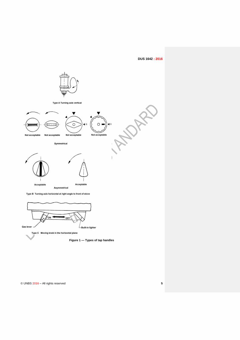
4.5.2 The 'ON', 'OFF' and any fixed position of tap handles shall be clearly and indelibly indicated or shall be obvious by design or position (see Figure 1). Where it is not obvious which tap operates which burner, some indication shall be given. All taps shall close in the same direction. Taps shall be designed so that when placed in any position and viewed from a distance of 3 m, will definitely indicate whether the tap is open or closed or in intermediate position. The direction of rotation of a tap knob (handle) flow off-on-simmer shall be anti-clockwise.
4.5.3 Where taps are fitted with adjustable stops, there shall be means for locking the stops in position. If screws are used for this purpose, they shall not lead into gas passages.
4.5.4 All taps shall lock in 'OFF' position and it shall be impossible for any tap handle or knob to move
accidentally by the weight of plug or handle or when caught by clothing. If this requirement is satisfied by means of an automatic locking device, the tap shall be easy to operate with one hand.
4.5.5 Taps shall be so made that in normal use and with reasonable application of the lubricant, gas passages do not become blocked.
4.5.6 Taps shall be lubricated with suitable grease, resistant to the action of biogas and capable of operating up to a temperature of 80 °C.
4.5.7 Each taper plug tap shall be spring loaded to maintain a gas tight fit. Helical springs fitted in taps shall be made of stainless steel material and shall have flattened ends which shall be rounded before fitting.
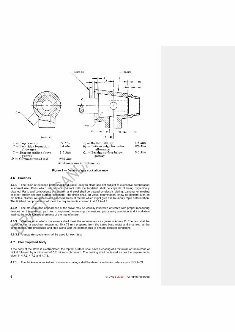
4.5.8 Taper plug taps shall have dimensional allowances when in 'OFF' position as given in Figure 3.
4.5.9 All controls or taps shall be easy to operate at all temperatures normally attained in use.
4.5.10 Screws, nuts, etc, which regulate the tension of taps or valve springs, shall not loosen in the operation of the stove. It shall not be possible to cause a leak during manual operation of the tap.
4.5.11 Taps shall have positive stops at 'OFF' and 'SIMMER' position.
4.5.12 Simmer flame, if provided, shall be obtained by fixed simmer orifice.
4.5.13 The igniting means adopted shall be sufficiently robust to withstand normal use without distortion or damage.
DUS 1642 : 2016
© UNBS 2016 – All rights reserved 5
Figure 1 — Types of tap handles
6 © UNBS 2016 – All rights reserved
Figure 2 — Details of gas cock allowance
4.6 Finishes
4.6.1 The finish of exposed parts shall be durable, easy to clean and not subject to excessive deterioration in normal use. Parts which will come in contact with the foodstuff shall be capable of being hygienically cleaned. Parts and components of cast iron and steel shall be treated by electric plating, painting, enameling or other proper anti-rust surface treatment. The finish shall, on visual examination, show no defects such as pin holes, blisters, roughness and exposed areas of metals which might give rise to unduly rapid deterioration. The finished components shall meet the requirements covered in 4.6.2 to 4.8.
4.6.2 The structure and appearance of the stove may be visually inspected or tested with proper measuring devices for the material, part and component processing dimensions, processing precision and installation against the technical requirements of the manufacturer.
4.6.3 Vitreous enamelled components shall meet the requirements as given in Annex C. The test shall be carried out on a specimen measuring 40 x 75 mm prepared from the same base metal and enamels, as the components, and processed and fired along with the components to ensure identical conditions.
4.6.3.1 A separate specimen shall be used for each test.
4.7 Electroplated body
If the body of the stove is electroplated, the top flat surface shall have a coating of a minimum of 10 microns of nickel followed by a minimum of 0.2 microns chromium. The coating shall be tested as per the requirements given in 4.7.1, 4.7.2 and 4.7.3.
4.7.1 The thickness of nickel and chromium coatings shall be determined in accordance with ISO 1463.
DUS 1642 : 2016
© UNBS 2016 – All rights reserved 7
4.7.2 Adhesion test
Cut a piece of a plated article, hold it in a vice and apply a coarse file to the cut edge in such a manner as to raise the deposit. There shall be no separation between the coating and the basis metal and the coating shall continue to adhere to the basis metal.
4.7.3 Corrosion resistance test
The plated article shall be subjected to the test for 12 hours as covered in ISO/TR 11728. The rating shall be assigned using the methods described in ISO 16151.
4.8 Paints or similar finishes
Surfaces finished in stoving paints or similar material shall conform to the following requirements:
a) Resistance to abrasion Painted surface shall be tested for resistance to scratching as described below:
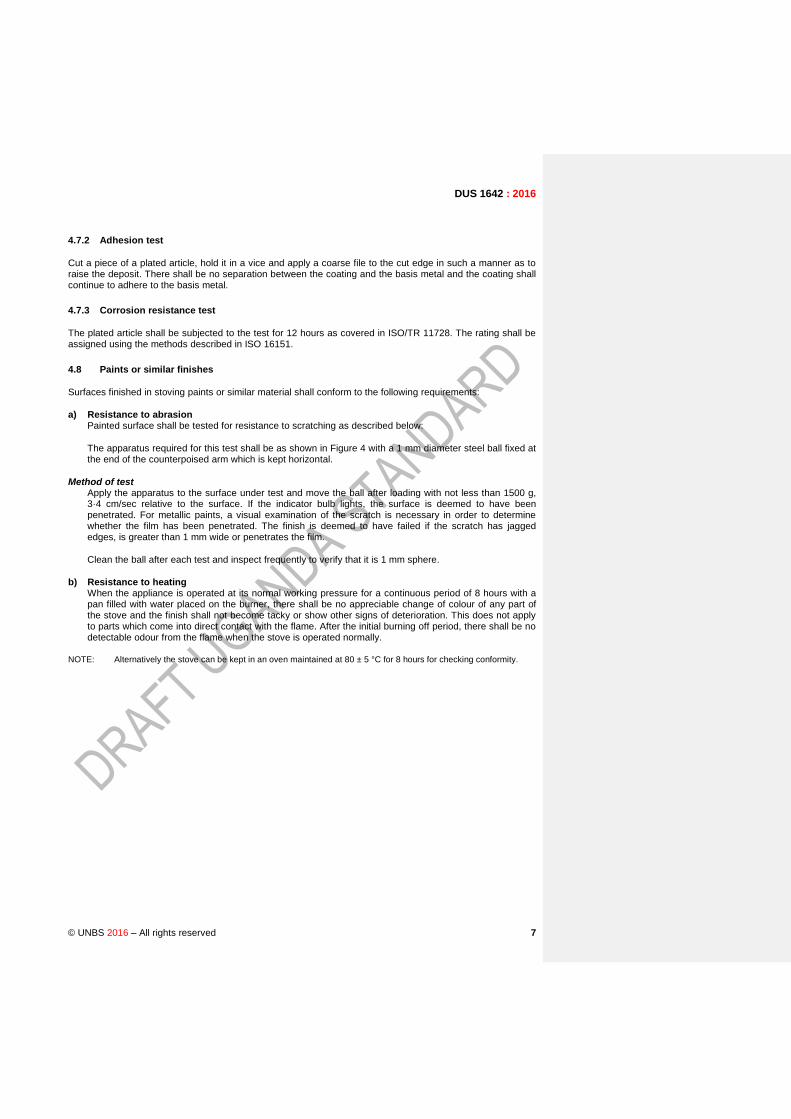
The apparatus required for this test shall be as shown in Figure 4 with a 1 mm diameter steel ball fixed at the end of the counterpoised arm which is kept horizontal.
Method of test Apply the apparatus to the surface under test and move the ball after loading with not less than 1500 g,
3·4 cm/sec relative to the surface. If the indicator bulb lights, the surface is deemed to have been penetrated. For metallic paints, a visual examination of the scratch is necessary in order to determine whether the film has been penetrated. The finish is deemed to have failed if the scratch has jagged edges, is greater than 1 mm wide or penetrates the film.
Clean the ball after each test and inspect frequently to verify that it is 1 mm sphere.
b) Resistance to heating When the appliance is operated at its normal working pressure for a continuous period of 8 hours with a
pan filled with water placed on the burner, there shall be no appreciable change of colour of any part of the stove and the finish shall not become tacky or show other signs of deterioration. This does not apply to parts which come into direct contact with the flame. After the initial burning off period, there shall be no detectable odour from the flame when the stove is operated normally.
NOTE: Alternatively the stove can be kept in an oven maintained at 80 ± 5 °C for 8 hours for checking conformity.

8 © UNBS 2016 – All rights reserved
Figure 4 — Paint scratch test apparatus
DUS 1642 : 2016
© UNBS 2016 – All rights reserved 9
4.9 Concealed gas supplies
Concealed tubular fittings liable to corrode shall be protected by bituminous paint or other equally protective material.
4.10 Screws, nuts, bolts and springs
All springs and those screws, nuts and bolts which are visible or which are to be removed for maintenance shall be of corrosion resistant material or treated to resist corrosion.
4.11 Injector jets
4.11.1 The injector jets shall be fixed calibrated type and it shall not be possible to loosen them without the use of the tools. The dimensions of the injector jet shall conform to the following requirements:
a) Across flat 10 mm, minimum
b) Projection from the face of mounting 6 mm, nominal
c) Threads M 8 x 1
d) Nozzle jet diameter 2.0 mm – 3.0 mm
4.11.2 The injector jet shall be made of metal, with or without ceramic tip. The melting point of the metal shall be not less than 650 °C.
4.11.3 The size of the jet in litres per hour of flow of biogas at STP conditions shall be impressed upon it.
4.12 Burners
4.12.1 The construction of the burners and the assembly shall allow their dismantling from the supports without the use of the tools (see Figure 5). Burners and parts of the burners (Burner caps in most cases) shall be interchangeable or replaceable without difficulty and affecting the performance of the burner.
4.12.2 The burner supports shall be rigid and shall be fixed in their place. Their construction shall ensure the stability of the burners and shall prevent their undue movement in horizontal plane.
4.12.3 Burner Nozzle and Burner Pipe shall be jointed by two good quality tack welding applied at opposite sides of the pipe. The tack welding also keeps the air regulating ring from slipping out. The tightness of the joints in the burner assembly shall not depend upon adhesives or any kind of packing.
4.12.4 In the case of stoves having more than one burner, one of the burners shall be of at least 450 l/h rating at STP.
4.12.5 For burners having centre flame, provision shall be made to protect the centre flame from pans resting directly on burner top and smothering the centre flame.
4.12.6 The parts of the burner shall not become disconnected during operation of the stove. If the burner is made and assembled in two or more parts they shall be so designed to provide proper self-loading arrangement so that they are always reassembled to its original design preventing any maladjustment in their assembly. This shall also be applicable for primary air regulators.
4.12.7 Air regulating ring shall be smooth and easy to operate, with no excess gap between two pipe for effective adjustment or regulation of air.
4.12.8 The jointing of burner pipe and burner cup shall be very strong, air tight and by means of araldite.

10 © UNBS 2016 – All rights reserved
4.13 Pan support
4.13.1 The design of the pan supports shall be such that it is practicable to support a pan of 125 mm diameter over at least one burner of the stove without the use of the loose rings and such that 150 mm diameter vessel remains stable over each burner. Prongs of the support shall have suitable taper to accommodate round, oval bottom pans and pots.
4.13.2 Loose pan supports shall be so designed that it is not possible to place them firmly in other than proper position.
4.13.3 There liquid containing plate shall be of an appropriate volume to containing the liquid spilling out during the boiling. The movable liquid containing plate shall be removed without using any tool and liquid containing plate integrated with the stove top shall be removable with ordinary tools.
4.13.4 The outer surface and inside of a biogas stove shall be conveniently cleaned and maintained.
Figure 5 — Burner assembly
Figure 6 — Inlet nozzle
4.14 Gas inlet connections
4.14.1 Where nozzles for flexible tubing are fitted, they shall be so positioned as to facilitate fitting of the tubing and also to prevent heating of the tubing to more than 60 °C. Shape of nozzle is given in Figure 6.
4.14.2 The pipe/tube used for main gas rail shall be of mild steel. The minimum wall thickness of the main gas rail shall be 1.6 mm + no limit/ -0.15 mm. The external surface of the gas rail shall be treated to resist corrosion. Any other connection made from the main gas rail shall be only metallic.
4.14.3 Screwed gas inlet and outlet connections shall conform to ISO 7-1.
DUS 1642 : 2016
© UNBS 2016 – All rights reserved 11
4.14.4 The position of the gas inlet shall allow connection to a gas supply on either side of the appliance with appliance fitted tight against a back wall. It shall be possible to change gas inlet from left to right easily by standard tools.
4.15 Gas soundness
All gas carrying parts of the stove shall be sound and these parts, when connected, shall conform to complete assembly which is sound against any gas leakage. The complete assembly shall be checked at 14.71 kN/m2. The details of the test are laid down in Annex D.
4.16 Strength test
When tested as specified in Annex E, the vertical resultant deflection of the top surface measured at the centre of length of the body shall not exceed 4 mm and the distance between the opposite sides (lengthwise and width-wise) shall not change by more than 5 mm.
5 Performance
5.1.1 Stoves shall be tested under conditions simulating as closely as possible to those under which it is designed to operate. During the test, the initial adjustment of the stove shall not be altered unless specifically required in the test procedure. Since the composition of biogas varies with its origin, it is necessary to adjust the stove to its maximum heat conditions before it is tested. The stove shall be adjusted and operated in accordance with the instructions issued with the stove. Before any tests are made, the stove shall be operated at its full working temperature for a sufficient period to remove any temporary finish which might interfere with observations. The gas system of the stove shall be examined for leaks before and after the test. The performance test results shall not be valid unless the system is sound.
5.1.2 The initial temperature of the room shall be between 25 to 30 °C.
5.1.3 Test system — The test system shall include biogas containers with a volume not less than 6 m3 and
a pressure governing device. During the testing, the pressure undulation shall be less than ±10 Pa.
5.1.4 Testing instruments shall be calibrated before application.
5.2 Gas consumption.
5.2.1 Each burner assembly under separate ON/OFF control shall give within ± 8 percent of the manufacturer's specified gas consumption in l/h at STP when tested with biogas at inlet pressure of 747 N/m2.
5.2.1.1 Multi-burner appliance (namely, appliance having more than one burner) shall give within +5 - 15percent of the declared total consumption in l/h at STP when all the burners are tested together with biogas at inlet pressure of 747 N/m2.
5.2.1.2 The gas consumption shall be measured by volume method using compressed air. The arrangement of the apparatus shall be similar to that given in Annex F. The measurements of volume shall be made with a wet gas flow meter and with minimum consumption of 30litres. The airflow thus found shall be converted to STP (27 °C and 760 mm of mercury). The air consumption thus found shall be converted to biogas consumption by multiplying 1.05.
5.2.2 It shall be possible to reduce the consumption rate of each of the burners to 40 percent or lower of the rated capacity.
5.2.2.1 When the gas consumption of a burner is reduced to simmer as described in 5.2.2, the flame shall not extinguish, blow off, strike back or form soot when tested with biogas at 747 N/m2.
12 © UNBS 2016 – All rights reserved
5.3 Ignition and flame travel
5.3.1 There shall be easy and safe access for lighting and re-lighting each burner by a match stick. With the vessel placed on the burner, if the flame is applied to any burner port and the gas in turned on, flame travel shall be complete within 4 s. Compliance is checked by recording with a stop watch the time that the flame transmitting to all the flame holes.
5.3.2 Electric ignition performance test, if applicable
5.3.2.1 Using battery igniter, the power voltage shall be adjusted to 70% of the rated pressure.
5.3.2.2 Under the rated pressure, the following operation procedures are proceeded with for ten times of ignition so as to check the ignition times. The procedures is to have several times of pre-ignition in advance with the ignition mode and speed depending on the igniter, specifically as follows:
a) For a single-firing type piezoelectric igniter, the one operation is one time, with each time controlled
within 0.5~1 s;
b) For a rotary igniter, one rotation is one time at a rotating speed of 0.5~1 s;
c) For a DC continuous discharge igniter, staying on a position of “Igniting” for 2 sec is considered as one time.
5.4 Flame stability
5.4.1 It shall be possible to operate the burner with taps fully open at gas inlet pressure of 747 N/m2 without the flame lift, blowing off, yellow flame or striking back.
5.4.2 Under 4 % (30Pa, 60Pa) of rated pressure, there shall be no light-back or flame-out of burner flame.
5.4.3 Wind resistance
5.4.3.1 Under windy condition, the combustion of a burner is stable without flame-out or light-back. Compliance is checked by performing the following test.
5.4.3.2 Under a pressure of 0.5 times of the rated pressure, igniting the stove and blowing with an ordinary fan when the combustion is stable under a condition the pot is not placed on the stove, so as to ensure a uniform wind field for the burner, and then determining the stability of the stove under a equal wind condition of 1m/s to that on the stove top.
5.4.4 Test for combustion stability
After 15s when the burner is ignited under a cold state and a pressure of 1.5 times of the rated pressure, it is considered as flame lift if the flame is separate from 1/3 of flame holes; after igniting the burner under a rated pressure, the flame is visually inspected for the clearness, uniformity and flame continuity; after 15min when the burner is ignited under a pressure of 0.5 times of the rated pressure, visually inspecting for light-back.
5.4.5 Pilot flame performance
Inspecting the burner for light-back or flame-out under a pressure of 30 N/m2 if the design rated pressure of the biogas stove is 800 N/m2, and under a pressure of 60 N/m2 if the design rated pressure is 1600 N/m2.
5.5 Noise control
5.5.1 Combustion noise shall be less than 65 dB and flameout noise shall be less than 85 dB.
DUS 1642 : 2016
© UNBS 2016 – All rights reserved 13
5.5.2 Test for the noise of a biogas stove under a pressure of 1.5 times of the rated pressure with an ordinary sound level instrument, at a position 1 m away from the front of the stove. The environmental background noise shall be less than 40 dB.
5.5.3 Flameout noise: test with a sound level meter according to the above requirements and reading the maximum noise value. The tested value is the maximum noise value plus 5 dB.
5.6 Formation of soot
A vessel 200 mm diameter and full of water shall be placed on the burner and the burner lighted at full 'ON' position of the tap with biogas inlet pressure of 747 N/m2
for one hour. After the test, no soot (unburnt carbon) shall be deposited on the burner and on the bottom of the vessel.
5.7 Flashback
A vessel having diameter suitable to cover the pan support and filled with water shall be placed on the burner under test. The tap of the burner shall be turned on and gas shall be allowed to flow through the burner at full rate with tap fully opened and gas lighted. After half an hour, the flame shall be immediately reduced to 40 percent of the rated capacity/simmer and brought back to full size. This operation shall be repeated five times. Then the burner shall be put off and immediately re-ignited. This operation shall also be repeated five times. During the test, no flash back shall occur.
5.8 Combustion
When tested in accordance with the details laid down in Annex G, carbon monoxide content of the exhaust gases of any burner operating at any consumption at which the flame is stable at gas inlet pressure of 747 N/m2 shall not exceed 500 parts per million (ppm).
5.9 Surface temperature
5.9.1 When operated for two hours, the temperature of no portion of the surface of stove other than a working surface, likely to be touched accidentally shall exceed 120 °C (working surfaces include pan-supports and burner heads).
5.9.2 Surfaces which, in normal use, have to be touched for short periods (for example, tap handles) shall not have a temperature exceeding 60 °C.
5.10 Thermal efficiency
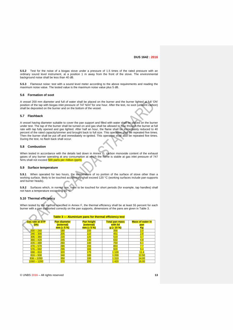
When tested by the method specified in Annex F, the thermal efficiency shall be at least 55 percent for each burner with a pan supported correctly on the pan supports, dimensions of the pans are given in Table 3.
Table 3 — Aluminium pans for thermal efficiency test
Gas rate at STP (l/h)
Pan diameter (external)
mm (± 5 %)
Pan height (external)
mm (± 5 %)
Total pan mass with lid
g (± 10 %)
Mass of water in pan Kg
000 – 240 180 100 356 2.0
246 – 300 205 110 451 2.8
306 – 360 220 120 519 3.7
366 – 420 245 130 632 4.8
426 – 480 260 140 750 6.1
476 – 570 285 155 853 7.7
576 – 692 295 165 920 9.4
698 – 810 320 175 1 100 11.4
816 – 930 340 185 1 200 12.50
936 – 1050 350 195 1 310 14.00
1060 – 1200 370 200 1 420 16.00

14 © UNBS 2016 – All rights reserved
1210 – 1360 380 210 1 530 18.00
1370 – 1600 400 215 1 640 20.00
NOTE 1 Distilled water (see EAS 123) shall be used for the test. Expel air by boiling for five minutes before test.
NOTE 2 the pans shall by cylindrical with flat bottom.
NOTE 3 the finish of the pan bottom from inside shall always be bright.
5.11 Ignition rate and performance of an electric igniter
5.11.1 At least 8 times of successful ignition in 10 times, without consecutive two times of ignition failure or deflagration.
5.11.2 Under 70% of rated battery voltage, the ignition performance of the igniter is normal.
5.12 Durability
5.12.1 Biogas plug valve shall conform to the air-tightness requirements after application of 6 000 times using the following procedure. Using air with the same rated pressure as that of the biogas, opening and
closing the valve at an operating speed of 5~20 times/min for 6000 times, under the condition that the plug
valve is separated from the stove or the plug valve is installed on the stove, so as to check the air tightness.
5.12.2 Electric igniter shall conform to the ignition requirements after application of 6 000 times. This is verified using the following procedure. Using biogas with the rated pressure or air with the same pressure,
opening and closing the valve at an operating speed of 5~20 times/min for 6000 times, under the condition
that the electric igniter is installed on the durability test instrument or stove, so as to check the electric ignition performance.
5.13 Classification of tests
5.13.1 Type tests
5.13.1.1 Type test shall be carried out in case of any one of the following conditions:
a) The type determination evaluation for new products or old product produced in another factory;
b) Any change in structure and/or material that may be related to the product performance, during normal production;
c) Resumption of production after a long-term suspension;
d) Type test required for certification of the product.
5.13.1.2 Samples for type approval test shall be randomly taken from products accepted in delivery test.
5.13.1.3 Acceptance by distribution department according to this standard.
5.13.2 The following shall constitute type tests:
a) Gas consumption (see 5.2),
b) Flash-back test for materials of burners (see 4.2.3 and Annex B),
c) Combustion (see 5.8 and Annex G),
d) Surface temperature (see 5.9), and
e) Thermal efficiency (see 5.10 and Annex F).
DUS 1642 : 2016
© UNBS 2016 – All rights reserved 15
f) Strength test (see 4.16 and Annex E)
g)durability
5.13.3 Routine tests
The following shall be carried out as routine tests:
a) Gas soundness (see 4.15),
b) Ignition and flame travel (see 5.3),
c) Flame stability (see 5.4),
d) Noise control (see 5.5),
e) Formation of soot (see 5.6), and
f) Flash back (see 5.7).
8 Process quality assurance control
8.1 General
The manufacturer shall consistently check the quality of the product during various stages of its manufacturing. Quality control at following points are recommended, however depending upon the procedure followed the manufacturer other suitable points of control may be included.
9.2 Raw materials
Raw materials shall be checked to ensure that they conform to the requirements of Clause 4.2.
6.3 Dimension
The dimensions of the finished product shall be strictly controlled and regularly checked to ensure that they conform to the dimensional requirements specified in the drawing.
6.4 Machining
Quality of the machining of the parts shall be checked immediately after each machining process. Parts shall be checked for any defects discovered during the process of machining, which was not predominant before machining.
6.5 Internal boring/ drilling shall be checked for diameter as well concentricity of the hole.
6.6 Side boring shall be checked for their position as well as their intersection with the main axis of the part
6.7 Welding
Quality of the welding joint shall be checked after each welding process
6.8 Quality plan
The supplier shall prepare a quality plan describing exactly how the specification and other quality requirements specified in this standard will be met. The plan shall clearly specify different inspection/ control
Commented [J O1]: Get parameters satisfying this condition
16 © UNBS 2016 – All rights reserved
points. The supplier shall maintain records of dimensional checks, visual inspection and other tests carried as a proof of conformance of the product to the requirements of this standard. The supplier shall preserve and present these records whenever required.
7 Instructions
Each stove shall be accompanied by an instruction sheet, card or leaflet giving the following information:
a) Brief instructions for installation, correct operation and maintenance of the stove;
b) Rating of each burner in L/h at STP;
c) Total gas consumption in L/h at STP
c) Working pressure of gas; and
8 Marking
8.1 A metallic plate incorporating the following shall be securely fixed in front of each stove:
a) Manufacturer's name, or registered trade-mark;
b) Total gas consumption in L/h at STP;
c) Rating of each burner in L/h at STP;
d) Batch number
e) Any special instruction for safe use;
f) Country of origin; and
g) The words 'For use with biogas at 747 N/m2.
h) Date of manufacture
i) The Standard the stove is complying with.
9 Packing
Biogas Stoves shall be suitably packed to prevent damage during transportation from the manufacturer's workshop to other storage. The cup and burner shall be held together by applying strong binding tape. Similarly the loose frame shall also be held to the body by applying similar strong binding tape. Each packing shall have a label, content of which shall be as shown in Clause 8 of this standard.
10 Sampling
This sampling plan shall be followed for any lot-wise inspection of the products for the purpose of lot acceptance
DUS 1642 : 2016
© UNBS 2016 – All rights reserved 17
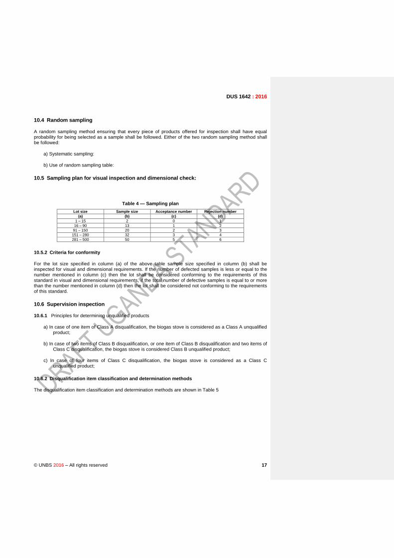
10.4 Random sampling
A random sampling method ensuring that every piece of products offered for inspection shall have equal probability for being selected as a sample shall be followed. Either of the two random sampling method shall be followed:
a) Systematic sampling:
b) Use of random sampling table:
10.5 Sampling plan for visual inspection and dimensional check:
Table 4 — Sampling plan
Lot size Sample size Acceptance number Rejection number
(a) (b) (c) (d)
1 – 15 2 0 1
16 – 90 13 1 2
91 – 150 20 2 3
151 – 280 32 3 4
281 – 500 50 5 6
10.5.2 Criteria for conformity
For the lot size specified in column (a) of the above table sample size specified in column (b) shall be inspected for visual and dimensional requirements. If the number of defected samples is less or equal to the number mentioned in column (c) then the lot shall be considered conforming to the requirements of this standard in visual and dimensional requirements, if the total number of defective samples is equal to or more than the number mentioned in column (d) then the lot shall be considered not conforming to the requirements of this standard.
10.6 Supervision inspection
10.6.1 Principles for determining unqualified products
a) In case of one item of Class A disqualification, the biogas stove is considered as a Class A unqualified product;
b) In case of two items of Class B disqualification, or one item of Class B disqualification and two items of Class C disqualification, the biogas stove is considered Class B unqualified product;
c) In case of four items of Class C disqualification, the biogas stove is considered as a Class C unqualified product;
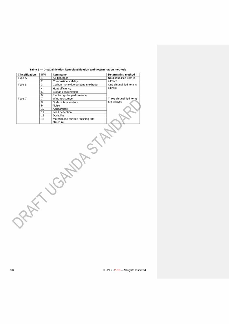
10.6.2 Disqualification item classification and determination methods
The disqualification item classification and determination methods are shown in Table 5
18 © UNBS 2016 – All rights reserved
Table 5 — Disqualification item classification and determination methods
Classification S/N Item name Determining method
Type A 1 Air-tightness No disqualified item is allowed 2 Combustion stability
Type B:
3 Carbon monoxide content in exhaust One disqualified item is allowed 4 Heat efficiency
5 Biogas consumption
6 Electric igniter performance
Type C 7 Wind resistance Three disqualified items are allowed 8 Surface temperature
9 Noise
10 Appearance
11 Load deflection
12 Durability
13 Material and surface finishing and structure

DUS 1642 : 2016
© UNBS 2016 – All rights reserved 19
Annex A (normative)
Method of test for plastic components
A.1 Method
A.1.1 The test shall be made in a dry products free heating cabinet. Where the plastic is integral with, pushed on or secured to another component, the stressed condition shall either be simulated or, where practicable, the plastics part shall be assembled to the mating component.
A.1.2 Visually inspect the component to establish its initial condition. Place the stressed component in the cabinet for a continuous period of 48 h at a temperature of 60 °C, after which inspect it again.
A.1.3 If during the final examination, it is observed that the plastics part has sustained any fissure, distortion, blemish or discoloration, it shall be deemed to have failed.

20 © UNBS 2016 – All rights reserved
Annex B (normative)
Method for flash back test for materials of burners
B.1 Procedure
B.1.1 The stove under test shall be set up to operate as far as possible in the manner expected in normal use paying due attention to the manufacturer's instructions. The gas supply shall be connected at an inlet pressure of 747 N/m2.
B.1.2 Each burner shall be ignited in turn and maintained with the flames flashed back into the mixing tube. The gas rate chosen for this may not necessarily be the highest gas rate that can be accommodated in the mixing tube but the rate most likely to cause flash back and which may cause melting or distortion of the burner. The burner shall be maintained with burner top in normal position for half an hour in flashback condition and subsequently examined for any distortion or melting.
DUS 1642 : 2016
© UNBS 2016 – All rights reserved 21
Annex C (normative)
Test appropriate to vitreous enamelled components
C.1 All enamelled components shall pass the tests given in C.1.1 and C.1.2.
C.1.1 Citric acid spot test
C.1.1.1 Apparatus
a) Dropper bottle or medicine dropper.
b) Watch-glass — 25 mm in diameter with fire-polished edge.
c) Towel — made of soft cotton.
C.1.1.2 Reagents
a) Citric acid solution — Dissolve 10 g of anhydrous citric acid crystals (H3C6H5O7) in 100 ml of water. Solution shall be prepared not more than 48 hours prior to use.
b) Cleaner solution — Dissolve 10 g of trisodium phosphate (Na3PO4) in one litre of tap water.
C.1.1.3 Test procedure
Clean the test specimen of all adhering dirt and grease by means of acetone. Thoroughly wash the area to be tested using a soft cotton towel moistened with warm one percent solution of trisodium phosphate. Rinse in warm running tap water and dry with a soft towel by blotting. Store the specimen at a temperature of 26 ± 1 °C for a time sufficient to bring it within this range of temperature prior to and during the test.
NOTE If, when rinsing, gathers in drops on the surface, washing treatment until the spreads evenly.
Select areas on the specimen that remain horizontal or nearly horizontal in service. Place the specimen in a position such that the flat area at least 38.1 mm in diameter is horizontal, with the specimen and the citric acid solution at 26 ± 1 °C, place several drops of the solution on the test area to form a pool, and immediately cover with a clean watch glass in inverted position. Use a quantity of solution that is just sufficient to fill the inverted watch-glass except for a small air bubble (three to six drops are usually required, depending upon the dropper and the curvature of the watch-glass). After 15 minutes of treatment, remove the watch-glass and immediately rinse the spot of solution from the surface. Dry the specimen with a dry, clean, soft cotton towel by blotting (not by rubbing).
Check the test specimen within two hours after exposure to the test solution. Draw two or more approximately parallel lines extending across the treated area by using the flat point of conventional graphite drafting pencil of degree 3B held in a normal writing position and applied with firm pressure. Now, rub the marks with a clean, soft cotton towel which has been dipped in water and wrung to expel any excess water. Do not use soap, abrasive or similar cleaning material.
The pencil mark shall be completely removed from treated area.
22 © UNBS 2016 – All rights reserved
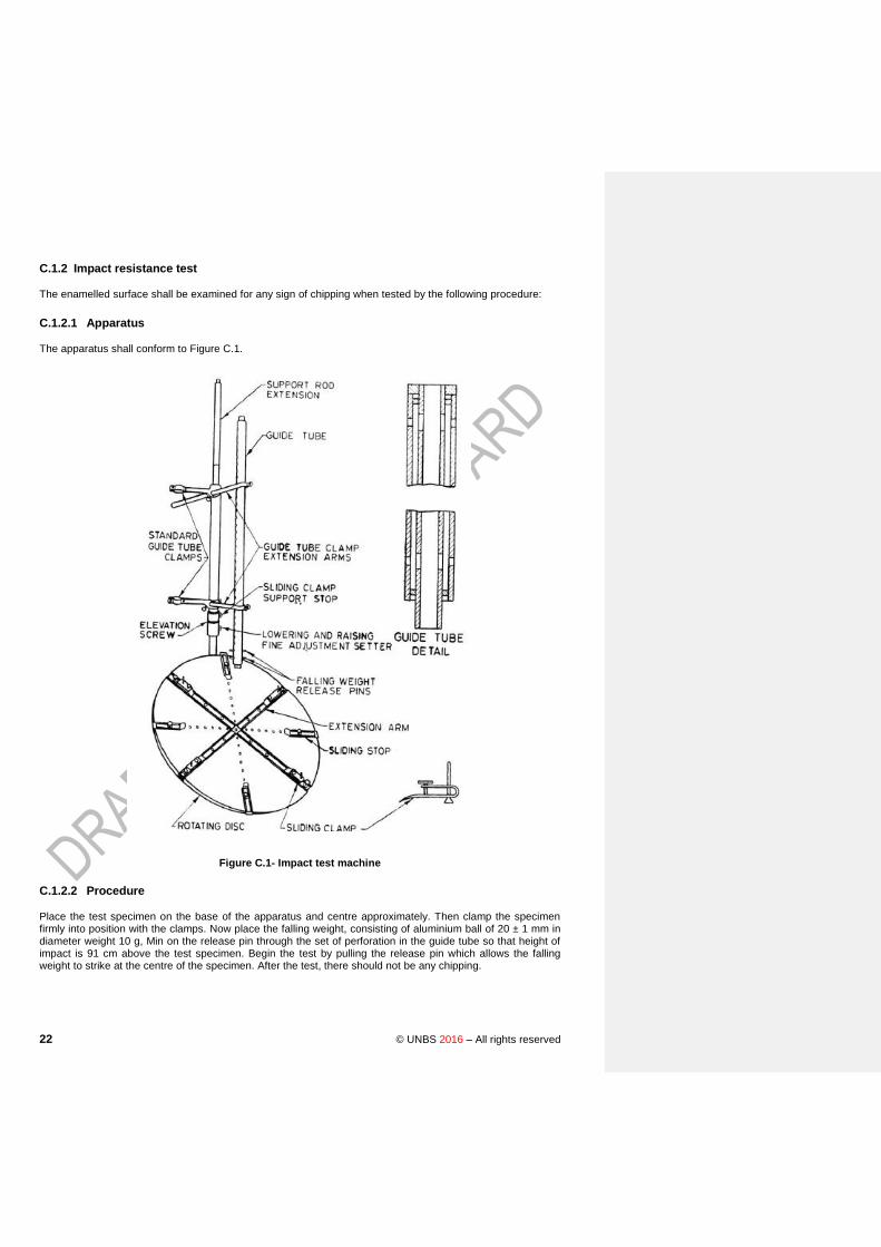
C.1.2 Impact resistance test
The enamelled surface shall be examined for any sign of chipping when tested by the following procedure:
C.1.2.1 Apparatus
The apparatus shall conform to Figure C.1.
Figure C.1- Impact test machine
C.1.2.2 Procedure
Place the test specimen on the base of the apparatus and centre approximately. Then clamp the specimen firmly into position with the clamps. Now place the falling weight, consisting of aluminium ball of 20 ± 1 mm in diameter weight 10 g, Min on the release pin through the set of perforation in the guide tube so that height of impact is 91 cm above the test specimen. Begin the test by pulling the release pin which allows the falling weight to strike at the centre of the specimen. After the test, there should not be any chipping.
DUS 1642 : 2016
© UNBS 2016 – All rights reserved 23
C.2 Thermal shock resistance test
C.2.1 Components on which water may spill in normal use shall be tested for thermal shock resistance. The enamelled surface shall be examined for any signs of flaking-off or cracking after undergoing cycles of test when tested by the following procedure:
C.2.1.1 Test procedure
Subject the test specimen to radiant heat, so as to reach a steady temperature of 185 to 195 °C in about 10 minutes in an oven. Remove the specimen within 5 seconds and quench the surface with 1 000 ml of water at 15 to 20 °C directed from an aspirator or other container through a 5 mm diameter tube, the end of tube being 150 mm above the centre of the heated portion of the test specimen and the flow rate being adjusted to 10 ml/sec (see Note). Dry the specimen, replace the same in position under the radiant heat source and repeat the procedure until six cycles have been completed. The specimen shall not show any sign of flaking off or cracking.
NOTE: It is convenient to mark the test area to ensure that water for quenching is correctly applied.
C.3 Pan supports, burners caps and burner baffles shall be tested by the following procedure.
Heat the components placed in position by lighting the burner in full 'ON' position with flat bottom pan containing water placed on the pan supports for half an hour. Extinguish the burner and allow the component to cool to atmospheric temperature. Repeat the heating and cooling treatment twice. At the end of the test, the component shall not show any sign of cracking, flaking and blistering.

24 © UNBS 2016 – All rights reserved
Annex D (normative)
Method of test for gas soundness
D.1 Procedure
D.1.1 The appliance shall be tested for gas soundness by the following method:
Subject the appliance to be tested to an air supply at a pressure of 14.71 kN/m2 with the bubble leak indicator (see Figure D.1) in the air supply line. Apply this pressure with all the taps of the appliance closed and examine the bubble indicator for the appearance of bubbles. The interval between the successive bubbles passing through it shall be not less than 10 seconds. Repeat the test with all the jets of the appliance sealed and all the taps open. Repeat the two tests after the taps have been turned 'ON' and 'OFF' ten times.
D.1.2 The following method shall be used to locate the point of leakage:
Immerse the appliance to be tested or the part through which the gas flows, assembled in working condition, in a water-bath at room temperature. Then connect it to an air supply at a pressure of 14.71 kN/m2 for a minimum period of 10 seconds with all the taps of the appliance closed and the appliance or the tested parts shall be examined for leakage of air. The test shall be repeated with all the jets sealed and all the taps opened. The two tests shall be repeated after all the taps have been turned 'OFF' and 'ON', ten times. The interval between successive bubbles passing through it shall be not less than 10 seconds.
Figure D.1 — Bubble leak indicator

DUS 1642 : 2016
© UNBS 2016 – All rights reserved 25
Annex E (normative)
Strength test
E.1 Procedure
E.1.1 The rubber support (grommet), if any, shall be removed and replaced with identical metal supports. The pan support and burner shall be removed and the distance between the sides of the appliance body being tested shall be measured.
A reference reading at the top surface of the body at the centre of the length shall be taken. A load of 250 newtons per burner shall be applied at the top surface subject to a minimum load of 500 Newtons for a single burner stove. The load shall be applied without impact to a strip of steel having 20 mm thickness, 100 mm width and as long as the length of the appliance (see Figure E.1). This strip shall be placed in the centre of the top surface of the appliance and its length parallel to the front. The load shall be maintained for 5 minutes after which the measurement for deflection at top surface of body (at the centre of the length just in front of the strip) shall be taken with the load in position.
Figure E.1 — Strength test
26 © UNBS 2016 – All rights reserved
Annex F (normative)
Gas consumption and thermal efficiency test
F.1 General
F.1.1 This procedure shall hold good for biogas burners up to 708 L/h capacity.
F.1.2 The capacity of biogas plant shall be at least 6 m3/day so as to have enough quantity of gas for the
tests, The plant shall be fed with cattle dung alone (cow, bullock or buffalo) so as to have biogas of approximately 55 percent methane and 45 percent carbon didioxide.
F.1.3 The gas plant shall be so located in relation to the place of testing that biogas at the required test pressure is available continuously without variation during the test. Suitable drainage shall be provided in the pipeline to drain the water condensate so as to get the gas for tests without pulsations.
F.1.4 The gas shall be analyzed for its composition on the basis of its constituents, the net calorific value shall be arrived at for saturated dry gas at STP. After deducting the proportion of carbon dioxide and oxygen in the biogas being used for the test, determined with the help of suitable means the remaining fraction shall be deemed to be methane. The net caloric value of methane at STP will be taken as 8.0 kcal/l.
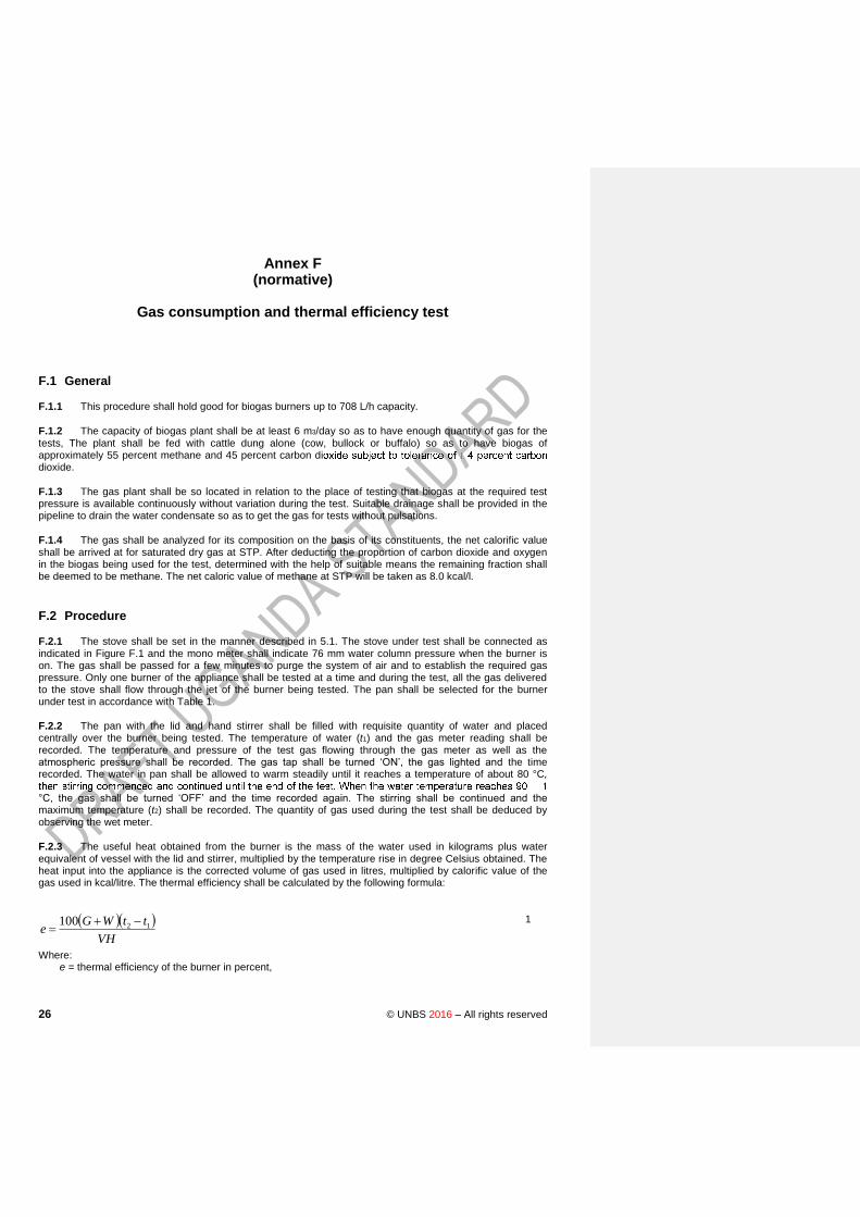
F.2 Procedure
F.2.1 The stove shall be set in the manner described in 5.1. The stove under test shall be connected as indicated in Figure F.1 and the mono meter shall indicate 76 mm water column pressure when the burner is on. The gas shall be passed for a few minutes to purge the system of air and to establish the required gas pressure. Only one burner of the appliance shall be tested at a time and during the test, all the gas delivered to the stove shall flow through the jet of the burner being tested. The pan shall be selected for the burner under test in accordance with Table 1.
F.2.2 The pan with the lid and hand stirrer shall be filled with requisite quantity of water and placed centrally over the burner being tested. The temperature of water (t1) and the gas meter reading shall be recorded. The temperature and pressure of the test gas flowing through the gas meter as well as the atmospheric pressure shall be recorded. The gas tap shall be turned ‘ON’, the gas lighted and the time recorded. The water in pan shall be allowed to warm steadily until it reaches a temperature of about 80 °C,
°C, the gas shall be turned ‘OFF’ and the time recorded again. The stirring shall be continued and the maximum temperature (t2) shall be recorded. The quantity of gas used during the test shall be deduced by observing the wet meter.
F.2.3 The useful heat obtained from the burner is the mass of the water used in kilograms plus water equivalent of vessel with the lid and stirrer, multiplied by the temperature rise in degree Celsius obtained. The heat input into the appliance is the corrected volume of gas used in litres, multiplied by calorific value of the gas used in kcal/litre. The thermal efficiency shall be calculated by the following formula:
1
Where: e = thermal efficiency of the burner in percent,
VH
ttWGe 12100

DUS 1642 : 2016
© UNBS 2016 – All rights reserved 27
G = quantity of water in the vessel in kg,
W = water equivalent of the vessel complete with lid and stirrer,
t1 = initial temperature of water in °C
t2 = final temperature of water in °C,
V = gas consumption in lit res, and
H = calorific value of the gas in kcal/l.
Figure F.1 — Thermal efficiency test for biogas stove

28 © UNBS 2016 – All rights reserved
Annex G (normative)
Method for determination of carbon monoxide
G.1 Procedure
G.1.1 The stove shall be set up in the manner described under 5.1. Before starting the test, a pan of 190 mm diameter and suitable height, and containing water sufficient for the test shall be placed over the stove. In addition a collecting hood suitable for the stoves under examination shall be obtained. The hood shall be so designed that while not interfering in any way with the normal combustion of the stove it collects a fairly high proportion of the products of combustion. Also, it shall be such that the sample collected represents the whole of the combustion gases and not those from one particular point. When using hood, the damper provided shall be set or additional flue pipe added so that the spillage of the flue gases around the skirt is just prevented. With the sampling hood in position over the stove under investigation, test gas at inlet pressure of 747 N/m2
shall be admitted and stove operated for ten minutes before the sampling is commenced. Any of the recognized methods may be used for gas analysis. 30
DUS 1642 : 2016
© UNBS 2016 – All rights reserved 29
Annex H (Informative)
Biogas Combustion
H.1 Combustion
Biogas burns in oxygen to give carbon dioxide and water and energy content in methane is released.
CH4 + 2O2 →CO2 + 2H2O + Energy
Each m3 of biogas releases about 20-24 MJ of energy. The oxygen required for combustion is taken from air, which contains approximately 21 per cent oxygen and 79 per cent nitrogen by volume. The chemical reaction is depicted below:
CH4 + 2O2 + 7.5 N2 →CO2 + 2H2O + 7.5 N2 + Energy
Thus, about 9.5 volumes of air per volume of combustion of methane are required to achieve complete oxidation. This is the stoichiometric methane-air mixture and is the optimum concentration of methane in air at which complete combustion occurs without unused air or fuel. The combustion of biogas involves mixing of air with fuel gas, adding heat in the form of a pilot and burning the resultant air-gas mixture. The chemical reaction of combustion of biogas (containing 60 % methane and 40 % carbon dioxide) and air mixture is shown below:
0.6 CH4 + 0.4 CO2 + 1.2 O2 + 4.5 N2 →CO2 + 1.2 H2O + 4.5 N2 + Energy
Thus, one volume of biogas requires 5.7 volumes of air or the stoichiometric requirement is 1/ (1+5.7) = 0.149, i.e., 14.9 per cent biogas in air.
The biogas burns over a narrow range of mixtures from approximately 9 per cent to 17 percent of biogas in air. If the flame is ‘too rich’, i.e., has too much fuel, then it will burn badly and incompletely, giving carbon monoxide, which is poisonous and soot particles. Therefore, the designs of appliances should aim at to maximize the conversion of methane into carbon dioxide in order to minimize the release of unburned methane and products of incomplete combustion.
The large quantity of carbon dioxide present in biogas poses a threat to stable combustion of biogas. CO2
traps not only heat but it also interacts with the flame which could potentially cool the flame down enough that it becomes unstable and blows out. Similarly, the water vapours present in biogas have a small but noticeable impact on flame temperature, inflammability limits, lower heating value and air-fuel ratio of biogas.
H.2 Flame
Biogas flame is cone shaped and consists of an inner cone and an outer mantle as shown in Figure B.1. When biogas and air mixture reaches the burner ports and burnt with a pilot heat, it forms a cone shaped blue flame. The cone shape of the flame is a result of laminar flow in a cylindrical mixing tube. The unburned gas is heated up in an inner cone and starts burning at the flame front. The mixture at the centre of the tube moves at a higher velocity than at the outside. In the main combustion zone, gas burns in the primary air and generates heat in the flame and combustion is completed at the outer mantle of the flame with the aid of secondary air or the flame from the sides. With the vertical rise of combustion products, i.e., carbon dioxide and water vapors, heat is transferred to the air close to the top of the flame. The hot air, which moves vertically away, draws in cooler secondary air to the base of the flame. The size of the inner cone depends on the primary aeration. A high proportion of primary air makes the flame much smaller and concentrated, giving higher flame temperature. If combustion is complete, which requires a temperature of less than 850 oC and residence time of less than 0.3 second, the flame is dark blue and almost invisible in daylight. If too little air is
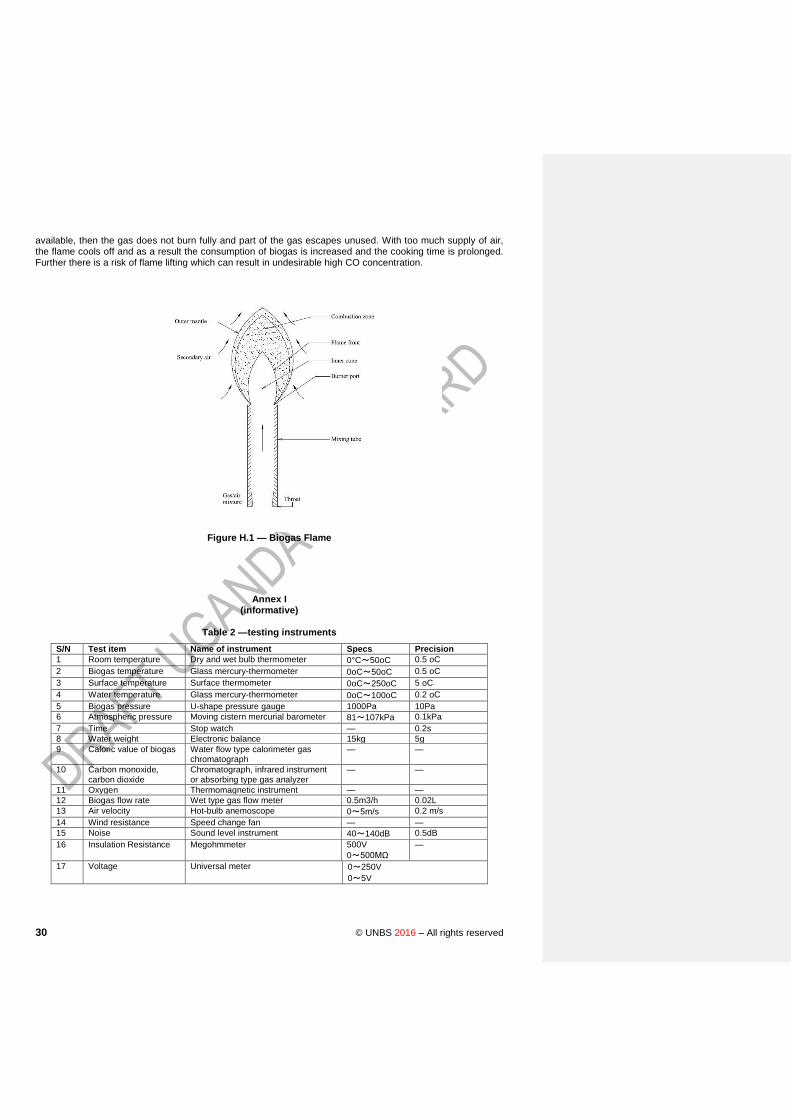
30 © UNBS 2016 – All rights reserved
available, then the gas does not burn fully and part of the gas escapes unused. With too much supply of air, the flame cools off and as a result the consumption of biogas is increased and the cooking time is prolonged. Further there is a risk of flame lifting which can result in undesirable high CO concentration.
Figure H.1 — Biogas Flame
Annex I (informative)
Table 2 —testing instruments
S/N Test item Name of instrument Specs Precision
1 Room temperature Dry and wet bulb thermometer 0°C~50oC 0.5 oC
2 Biogas temperature Glass mercury-thermometer 0oC~50oC 0.5 oC
3 Surface temperature Surface thermometer 0oC~250oC 5 oC
4 Water temperature Glass mercury-thermometer 0oC~100oC 0.2 oC
5 Biogas pressure U-shape pressure gauge 1000Pa 10Pa
6 Atmospheric pressure Moving cistern mercurial barometer 81~107kPa 0.1kPa
7 Time Stop watch — 0.2s
8 Water weight Electronic balance 15kg 5g
9 Caloric value of biogas Water flow type calorimeter gas chromatograph
— —
10 Carbon monoxide, carbon dioxide
Chromatograph, infrared instrument or absorbing type gas analyzer
— —
11 Oxygen Thermomagnetic instrument — —
12 Biogas flow rate Wet type gas flow meter 0.5m3/h 0.02L
13 Air velocity Hot-bulb anemoscope 0~5m/s 0.2 m/s
14 Wind resistance Speed change fan — —
15 Noise Sound level instrument 40~140dB 0.5dB
16 Insulation Resistance Megohmmeter 500V
0~500MΩ
—
17 Voltage Universal meter 0~250V
0~5V

DUS 1642 : 2016
© UNBS 2016 – All rights reserved 31

32 © UNBS 2016 – All rights reserved
Bibliography
[1]
WDUS 0015: 2015
© UNBS 2016 – All rights reserved 33
Certification marking
Products that conform to Uganda standards may be marked with Uganda National Bureau of Standards (UNBS) Certification Mark shown in the figure below.
The use of the UNBS Certification Mark is governed by the Standards Act, and the Regulations made thereunder. This mark can be used only by those licensed under the certification mark scheme operated by the Uganda National Bureau of Standards and in conjunction with the relevant Uganda Standard. The presence of this mark on a product or in relation to a product is an assurance that the goods comply with the requirements of that standard under a system of supervision, control and testing in accordance with the certification mark scheme of the Uganda National Bureau of Standards. UNBS marked products are continually checked by UNBS for conformity to that standard.
Further particulars of the terms and conditions of licensing may be obtained from the Director, Uganda National Bureau of Standards.
US nnnn-n: yyyy
ICS nn.nnn.nn
Price based on nn pages
© UNBS yyyy– All rights reserved