DuraGalPlus Verandah Beam - Austubemills · 2 DuraGalPlus® verandah beam spanning tables ... •...
68
DuraGalPlus ® Verandah Beam Spanning tables Technical specifications
Transcript of DuraGalPlus Verandah Beam - Austubemills · 2 DuraGalPlus® verandah beam spanning tables ... •...
DuraGalPlus®
Verandah Beam Spanning tables
Technical specifications
2 DuraGalPlus® verandah beam spanning tables - May 2017
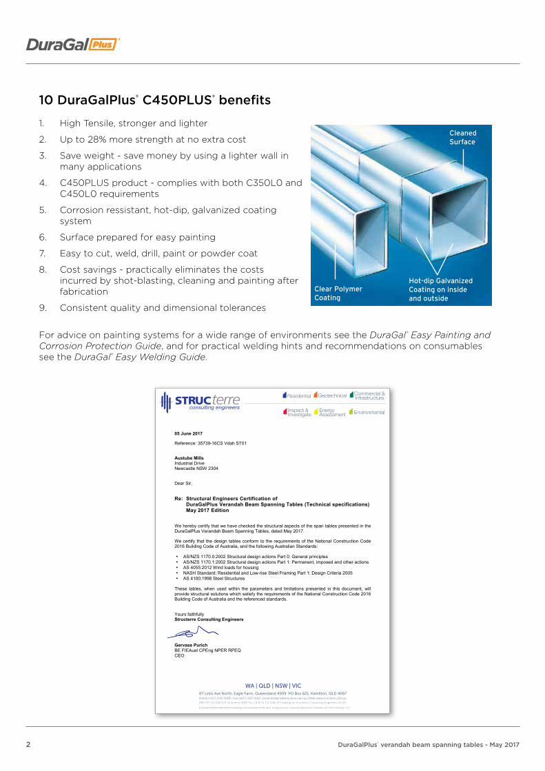
10 DuraGalPlus® C450PLUS® benefits
1. High Tensile, stronger and lighter
2. Up to 28% more strength at no extra cost
3. Save weight - save money by using a lighter wall in many applications
4. C450PLUS product - complies with both C350L0 and C450L0 requirements
5. Corrosion ressistant, hot-dip, galvanized coating system
6. Surface prepared for easy painting
7. Easy to cut, weld, drill, paint or powder coat
8. Cost savings - practically eliminates the costs incurred by shot-blasting, cleaning and painting after fabrication
9. Consistent quality and dimensional tolerances
For advice on painting systems for a wide range of environments see the DuraGal® Easy Painting and Corrosion Protection Guide, and for practical welding hints and recommendations on consumables see the DuraGal® Easy Welding Guide.
Clear PolymerCoating
CleanedSurface
Hot-dip Galvanized Coating on inside and outside
R:\Jobs\2014\35000-35999\35739-14\Drawings & Docs\Verandah\35739-16CS - Duragal Domectic Construction Manual Vol1 Certification 2017.05.31.docxPage 1 of 1
05 June 2017
Reference: 35739-16CS Vdah ST01
Austube Mills Industrial Drive Newcastle NSW 2304
Dear Sir,
Re: Structural Engineers Certification of DuraGalPlus Verandah Beam Spanning Tables (Technical specifications) May 2017 Edition
We hereby certify that we have checked the structural aspects of the span tables presented in the DuraGalPlus Verandah Beam Spanning Tables, dated May 2017.
We certify that the design tables conform to the requirements of the National Construction Code 2016 Building Code of Australia, and the following Australian Standards:
• AS/NZS 1170.0:2002 Structural design actions Part 0: General principles • AS/NZS 1170.1:2002 Structural design actions Part 1: Permanent, imposed and other actions • AS 4055:2012 Wind loads for housing • NASH Standard: Residential and Low-rise Steel Framing Part 1: Design Criteria 2005 • AS 4100:1998 Steel Structures
These tables, when used within the parameters and limitations presented in this document, will provide structural solutions which satisfy the requirements of the National Construction Code 2016 Building Code of Australia and the referenced standards.
Yours faithfully Structerre Consulting Engineers Gervase Purich BE FIEAust CPEng NPER RPEQ CEO
3DuraGalPlus® verandah beam spanning tables - May 2017
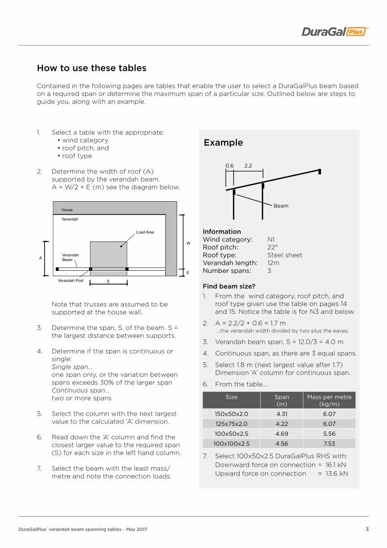
InformationWind category: N1Roof pitch: 22°Roof type: Steel sheetVerandah length: 12mNumber spans: 3
Find beam size?1. From the wind category, roof pitch, and
roof type given use the table on pages 14 and 15. Notice the table is for N3 and below.
2. A = 2.2/2 + 0.6 = 1.7 m ...the verandah width divided by two plus the eaves.
3. Verandah beam span, S = 12.0/3 = 4.0 m.
4. Continuous span, as there are 3 equal spans.
5. Select 1.8 m (next largest value after 1.7) Dimension ‘A’ column for continuous span.
6. From the table...
Size Span (m)
Mass per metre (kg/m)
150x50x2.0 4.31 6.07
125x75x2.0 4.22 6.07
100x50x2.5 4.69 5.56
100x100x2.5 4.56 7.53
7. Select 100x50x2.5 DuraGalPlus RHS with: Downward force on connection = 16.1 kN Upward force on connection = 13.6 kN
1. Select a table with the appropriate:• wind category• roof pitch, and• roof type
2. Determine the width of roof (A) supported by the verandah beam.
A = W/2 + E (m) see the diagram below.
Note that trusses are assumed to be supported at the house wall.
3. Determine the span, S, of the beam. S = the largest distance between supports.
4. Determine if the span is continuous or single:
Single span... one span only, or the variation between
spans exceeds 30% of the larger span Continuous span... two or more spans
5. Select the column with the next largest value to the calculated ‘A’ dimension.
6. Read down the ‘A’ column and find the closest larger value to the required span (S) for each size in the left hand column.
7. Select the beam with the least mass/metre and note the connection loads.
How to use these tables
Contained in the following pages are tables that enable the user to select a DuraGalPlus beam based on a required span or determine the maximum span of a particular size. Outlined below are steps to guide you, along with an example.
Example
House
Verandah
Load Area
Verandah Post
VerandahBeam
W
E
A
S
Beam
2.20.6
4 DuraGalPlus® verandah beam spanning tables - May 2017
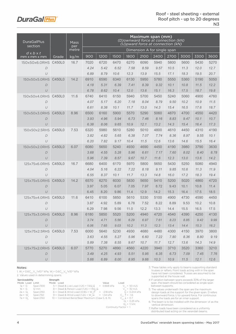
DuraGalPlus section
d x b x tmm x mm x mm Grade
Mass per
metre
kg/m
Maximum span (mm)(D)ownward force at connection (kN)
(U)pward force at connection (kN)
Dimension A for single span
900 1200 1500 1800 2100 2400 2700 3000 3300 3600
150x50x6.0RHS C450L0 16.7 7020 6720 6470 6270 6090 5940 5800 5600 5430 5270D 4.24 5.42 6.52 7.58 8.59 9.57 10.5 11.3 12.0 12.7U 6.89 8.79 10.6 12.3 13.9 15.5 17.1 18.3 19.5 20.7
150x50x5.0RHS C450L0 14.2 6910 6590 6340 6130 5950 5780 5550 5360 5190 5050D 4.18 5.31 6.39 7.41 8.39 9.32 10.1 10.8 11.5 12.2U 6.78 8.62 10.4 12.0 13.6 15.1 16.3 17.5 18.7 19.8
150x50x4.0RHS C450L0 11.6 6740 6410 6150 5940 5700 5450 5240 5060 4900 4760D 4.07 5.17 6.20 7.18 8.04 8.79 9.50 10.2 10.9 11.5U 6.61 8.38 10.1 11.7 13.0 14.3 15.4 16.5 17.6 18.7
150x50x3.0RHS C450L0 8.96 6500 6160 5900 5570 5290 5060 4870 4700 4550 4420D 3.93 4.96 5.94 6.73 7.46 8.16 8.83 9.47 10.1 10.7U 6.38 8.06 9.65 10.9 12.1 13.2 14.3 15.4 16.4 17.3
150x50x2.5RHS C450L0 7.53 6320 5980 5610 5280 5010 4800 4610 4450 4310 4190D 3.82 4.82 5.65 6.38 7.07 7.74 8.36 8.97 9.55 10.1U 6.20 7.82 9.17 10.4 11.5 12.6 13.6 14.6 15.5 16.4
150x50x2.0RHS C450L0 6.07 6080 5650 5240 4930 4690 4450 4190 3980 3790 3630D 3.68 4.55 5.28 5.96 6.61 7.17 7.60 8.02 8.40 8.78U 5.96 7.39 8.57 9.67 10.7 11.6 12.3 13.0 13.6 14.2
125x75x6.0RHS C450L0 16.7 6680 6400 6170 5970 5800 5650 5430 5250 5080 4940D 4.04 5.16 6.22 7.22 8.18 9.11 9.85 10.6 11.3 11.9U 6.55 8.37 10.1 11.7 13.3 14.8 16.0 17.2 18.3 19.4
125x75x5.0RHS C450L0 14.2 6570 6270 6030 5830 5650 5410 5200 5020 4860 4720D 3.97 5.05 6.07 7.05 7.97 8.72 9.43 10.1 10.8 11.4U 6.45 8.20 9.86 11.4 12.9 14.2 15.3 16.4 17.5 18.5
125x75x4.0RHS C450L0 11.6 6410 6100 5850 5610 5330 5100 4900 4730 4590 4450D 3.87 4.92 5.89 6.78 7.52 8.22 8.89 9.53 10.2 10.8U 6.29 7.98 9.56 11.0 12.2 13.3 14.4 15.5 16.5 17.5
125x75x3.0RHS C450L0 8.96 6180 5850 5520 5200 4940 4720 4540 4390 4250 4130D 3.74 4.71 5.56 6.29 6.97 7.61 8.23 8.85 9.42 9.99
U 6.06 7.65 9.03 10.2 11.3 12.3 13.4 14.4 15.3 16.2
125x75x2.5RHS C450L0 7.53 6000 5640 5230 4930 4680 4480 4300 4150 3970 3800D 3.63 4.55 5.27 5.96 6.60 7.22 7.80 8.36 8.80 9.19U 5.89 7.38 8.55 9.67 10.7 11.7 12.7 13.6 14.3 14.9
125x75x2.0RHS C450L0 6.07 5770 5270 4890 4560 4220 3940 3710 3520 3360 3210D 3.49 4.25 4.93 5.51 5.95 6.35 6.73 7.09 7.45 7.76U 5.66 6.89 8.00 8.95 9.66 10.3 10.9 11.5 12.1 12.6
Roof - steel sheeting - externalRoof pitch - up to 20 degrees
N3
Notes:1. Wu= 0.6Cp,nVhu
2x10⁻³ kPa, Ws= 0.6Cp,nVhs2x10-3 kPa
2. Values used in determining spans.
Serviceability StrengthMode Load Limit Mode Load Value Load
1a = G Span/300 5 = Dead & Live Load (1.2G + 1.5Q1)↓ = 0.668 kPa Vhu = 50 m/s1b = G 12 mm 8 = Dead & Person Load (1.2G + 1.5Q2)↓ Vhs = 32 m/s2a = Q1 Span/250 6 = Dead & Wind Load (0.9G + Wu)↑ = -2.18 kPa G = 0.244 kPa4a = Ws Span/150 9 = Dead & Wind Load (1.2G + Wu)↓ = 1.34 kPa Cp,n ↑ = -1.67a = Q2 Span/250 10 = Combined Bend/Bear Maximum (Case 5, 8, 9) Cp,n ↓ = 0.7
Q1 = 0.25 kPaQ2 = 1.1 kN
Continuity Factor = 1
3. These tables only apply to beams supporting standard trusses or rafters. Point loads acting with in the span have not been considered. Trusses are assumed to be supported at the house wall.
4 If variation between spans exceeds 30% of the larger span, the beam should be considered as single span between supports.
5. The values underneath the span are the maximum design loads at the support for the given span. D refers to downward force, U to upward force. For continuous spans the loads are for an inner support.
6. The beam is to be installed with the dimension ‘d’ as the vertical dimension.
7. Rafter loads have been considered as a uniformly distributed load acting on the verandah beams.

5DuraGalPlus® verandah beam spanning tables - May 2017
DuraGalPlus section
d x b x tmm x mm x mm Grade
Mass per
metre
kg/m
Maximum span (mm)(D)ownward force at connection (kN)
(U)pward force at connection (kN)
Dimension A for single span
900 1200 1500 1800 2100 2400 2700 3000 3300 3600
100x50x5.0RHS C450L0 10.3 5440 5100 4730 4450 4230 4050 3890 3760 3640 3540D 3.29 4.11 4.77 5.38 5.97 6.53 7.05 7.58 8.07 8.56U 5.34 6.67 7.73 8.73 9.68 10.6 11.4 12.3 13.1 13.9
100x50x4.0RHS C450L0 8.49 5310 4840 4490 4230 4020 3840 3690 3570 3460 3360D 3.21 3.90 4.52 5.11 5.67 6.19 6.69 7.19 7.67 8.12U 5.21 6.33 7.34 8.30 9.20 10.0 10.9 11.7 12.4 13.2
100x50x3.5RHS C450L0 7.53 5150 4680 4340 4090 3880 3710 3570 3450 3340 3250D 3.11 3.77 4.37 4.94 5.47 5.98 6.47 6.95 7.40 7.86U 5.05 6.12 7.10 8.02 8.88 9.71 10.5 11.3 12.0 12.8
100x50x3.0RHS C450L0 6.6 4980 4520 4200 3950 3750 3590 3450 3330 3230 3130D 3.01 3.64 4.23 4.78 5.29 5.79 6.26 6.71 7.16 7.57U 4.89 5.91 6.87 7.75 8.58 9.39 10.2 10.9 11.6 12.3
100x50x2.5RHS C450L0 5.56 4730 4290 3990 3750 3560 3410 3280 3160 3060 2980D 2.86 3.46 4.02 4.53 5.02 5.50 5.95 6.37 6.78 7.21U 4.64 5.61 6.52 7.36 8.15 8.92 9.65 10.3 11.0 11.7
100x50x2.0RHS C450L0 4.50 4430 4020 3730 3510 3340 3190 3070 2960 2870 2750D 2.68 3.24 3.76 4.24 4.71 5.14 5.57 5.96 6.36 6.65U 4.35 5.26 6.10 6.89 7.65 8.35 9.04 9.68 10.3 10.8
100x50x1.6RHS C450L0 3.64 4140 3760 3490 3220 2980 2790 2630 2490 2380 2270D 2.50 3.03 3.52 3.89 4.20 4.50 4.77 5.02 5.28 5.49U 4.06 4.92 5.71 6.32 6.82 7.30 7.74 8.14 8.56 8.91
100x100x3.0SHS C450L0 8.96 5710 5360 4970 4680 4440 4250 4090 3950 3820 3710D 3.45 4.32 5.01 5.66 6.26 6.85 7.42 7.96 8.47 8.97U 5.60 7.01 8.13 9.18 10.2 11.1 12.0 12.9 13.7 14.6
100x100x2.5SHS C450L0 7.53 5540 5080 4710 4430 4210 4030 3810 3620 3450 3300D 3.35 4.09 4.75 5.36 5.94 6.50 6.91 7.29 7.65 7.98U 5.43 6.64 7.70 8.69 9.64 10.5 11.2 11.8 12.4 12.9
100x100x2.0SHS C450L0 6.07 5220 4740 4360 3970 3670 3430 3230 3070 2920 2800D 3.16 3.82 4.39 4.80 5.18 5.53 5.86 6.19 6.47 6.77U 5.12 6.20 7.13 7.79 8.40 8.97 9.51 10.0 10.5 11.0
90x90x2.0SHS C450L0 5.45 4690 4260 3950 3660 3380 3160 2980 2830 2690 2580D 2.83 3.43 3.98 4.42 4.77 5.09 5.40 5.70 5.96 6.24U 4.60 5.57 6.46 7.18 7.74 8.27 8.77 9.25 9.68 10.1
Roof - steel sheeting - externalRoof pitch - up to 20 degreesN3
Notes:1. Wu= 0.6Cp,nVhu
2x10⁻³ kPa, Ws= 0.6Cp,nVhs2x10-3 kPa
2. Values used in determining spans.
Serviceability StrengthMode Load Limit Mode Load Value Load
1a = G Span/300 5 = Dead & Live Load (1.2G + 1.5Q1)↓ = 0.668 kPa Vhu = 50 m/s1b = G 12 mm 8 = Dead & Person Load (1.2G + 1.5Q2)↓ Vhs = 32 m/s2a = Q1 Span/250 6 = Dead & Wind Load (0.9G + Wu)↑ = -2.18 kPa G = 0.244 kPa4a = Ws Span/150 9 = Dead & Wind Load (1.2G + Wu)↓ = 1.34 kPa Cp,n ↑ = -1.67a = Q2 Span/250 10 = Combined Bend/Bear Maximum (Case 5, 8, 9) Cp,n ↓ = 0.7
Q1 = 0.25 kPaQ2 = 1.1 kN
Continuity Factor = 1
3. These tables only apply to beams supporting standard trusses or rafters. Point loads acting with in the span have not been considered. Trusses are assumed to be supported at the house wall.
4 If variation between spans exceeds 30% of the larger span, the beam should be considered as single span between supports.
5. The values underneath the span are the maximum design loads at the support for the given span. D refers to downward force, U to upward force. For continuous spans the loads are for an inner support.
6. The beam is to be installed with the dimension ‘d’ as the vertical dimension.
7. Rafter loads have been considered as a uniformly distributed load acting on the verandah beams.

6 DuraGalPlus® verandah beam spanning tables - May 2017
DuraGalPlus section
d x b x tmm x mm x mm Grade
Mass per
metre
kg/m
Maximum span (mm)(D)ownward force at connection (kN)
(U)pward force at connection (kN)
Dimension A for continuous span
900 1200 1500 1800 2100 2400 2700 3000 3300 3600
150x50x6.0RHS C450L0 16.7 8740 8370 8070 7810 7590 7400 7170 6800 6470 6190D 13.2 16.9 20.3 23.6 26.8 29.8 32.5 34.3 35.9 37.4U 21.4 27.4 33.0 38.3 43.4 48.4 52.8 55.6 58.2 60.7
150x50x5.0RHS C450L0 14.2 8600 8210 7900 7640 7410 7070 6660 6310 6010 5750D 13.0 16.5 19.9 23.1 26.1 28.5 30.2 31.8 33.3 34.8U 21.1 26.8 32.3 37.5 42.4 46.2 49.0 51.6 54.0 56.4
150x50x4.0RHS C450L0 11.6 8390 7990 7660 7400 6880 6430 6050 5740 5470 5230D 12.7 16.1 19.3 22.4 24.3 25.9 27.4 28.9 30.3 31.6U 20.6 26.1 31.3 36.3 39.4 42.1 44.5 46.9 49.2 51.3
150x50x3.0RHS C450L0 8.96 8100 7680 7230 6580 6090 5690 5360 5080 4840 4630D 12.2 15.5 18.2 19.9 21.5 22.9 24.3 25.6 26.8 28.0U 19.9 25.1 29.6 32.3 34.9 37.2 39.4 41.5 43.5 45.4
150x50x2.5RHS C450L0 7.53 7870 7440 6630 6050 5590 5220 4890 4590 4330 4100D 11.9 15.0 16.7 18.3 19.7 21.0 22.2 23.1 24.0 24.8U 19.3 24.3 27.1 29.7 32.0 34.1 36.0 37.5 38.9 40.2
150x50x2.0RHS C450L0 6.07 7140 6020 5250 4680 4240 3890 3600 3350 3140 2950D 10.8 12.1 13.2 14.1 15.0 15.7 16.3 16.9 17.4 17.8U 17.5 19.7 21.5 23.0 24.3 25.4 26.5 27.4 28.2 28.9
125x75x6.0RHS C450L0 16.7 8330 7970 7680 7440 7230 7040 6880 6530 6220 5950D 12.6 16.1 19.3 22.5 25.5 28.4 31.2 32.9 34.5 36.0U 20.4 26.1 31.4 36.5 41.4 46.0 50.6 53.4 55.9 58.4
125x75x5.0RHS C450L0 14.2 8190 7820 7520 7270 7050 6790 6400 6060 5770 5520D 12.4 15.8 18.9 22.0 24.9 27.4 29.0 30.5 32.0 33.4U 20.1 25.6 30.7 35.7 40.3 44.4 47.1 49.5 51.9 54.2
125x75x4.0RHS C450L0 11.6 7980 7600 7290 7030 6610 6170 5810 5510 5250 5020D 12.1 15.3 18.4 21.2 23.3 24.9 26.3 27.8 29.1 30.3U 19.6 24.9 29.8 34.5 37.8 40.4 42.7 45.0 47.2 49.2
125x75x3.0RHS C450L0 8.96 7690 7290 6870 6260 5790 5410 5100 4830 4600 4410D 11.6 14.7 17.3 18.9 20.4 21.8 23.1 24.3 25.5 26.7
U 18.9 23.8 28.1 30.7 33.1 35.4 37.5 39.5 41.4 43.3
125x75x2.5RHS C450L0 7.53 7470 6640 5930 5400 4990 4670 4400 4170 3970 3800D 11.3 13.4 14.9 16.3 17.6 18.8 19.9 21.0 22.0 23.0U 18.3 21.7 24.2 26.5 28.6 30.5 32.4 34.1 35.7 37.3
125x75x2.0RHS C450L0 6.07 6490 5600 5000 4560 4160 3840 3570 3350 3150 2980D 9.81 11.3 12.6 13.8 14.7 15.5 16.2 16.9 17.5 18.0U 15.9 18.3 20.4 22.4 23.8 25.1 26.3 27.4 28.3 29.2
Roof - steel sheeting - externalRoof pitch - up to 20 degrees
N3
Notes:1. Wu= 0.6Cp,nVhu
2x10⁻³ kPa, Ws= 0.6Cp,nVhs2x10-3 kPa
2. Values used in determining spans.
Serviceability StrengthMode Load Limit Mode Load Value Load
1a = G Span/300 5 = Dead & Live Load (1.2G + 1.5Q1)↓ = 0.668 kPa Vhu = 50 m/s1b = G 12 mm 8 = Dead & Person Load (1.2G + 1.5Q2)↓ Vhs = 32 m/s2a = Q1 Span/250 6 = Dead & Wind Load (0.9G + Wu)↑ = -2.18 kPa G = 0.244 kPa4a = Ws Span/150 9 = Dead & Wind Load (1.2G + Wu)↓ = 1.34 kPa Cp,n ↑ = -1.67a = Q2 Span/250 10 = Combined Bend/Bear Maximum (Case 5, 8, 9) Cp,n ↓ = 0.7
Q1 = 0.25 kPaQ2 = 1.1 kN
Continuity Factor = 1
3. These tables only apply to beams supporting standard trusses or rafters. Point loads acting with in the span have not been considered. Trusses are assumed to be supported at the house wall.
4 If variation between spans exceeds 30% of the larger span, the beam should be considered as single span between supports.
5. The values underneath the span are the maximum design loads at the support for the given span. D refers to downward force, U to upward force. For continuous spans the loads are for an inner support.
6. The beam is to be installed with the dimension ‘d’ as the vertical dimension.
7. Rafter loads have been considered as a uniformly distributed load acting on the verandah beams.

7DuraGalPlus® verandah beam spanning tables - May 2017
DuraGalPlus section
d x b x tmm x mm x mm Grade
Mass per
metre
kg/m
Maximum span (mm)(D)ownward force at connection (kN)
(U)pward force at connection (kN)
Dimension A for continuous span
900 1200 1500 1800 2100 2400 2700 3000 3300 3600100x50x5.0RHS C450L0 10.3 6780 6440 6170 5800 5360 5010 4710 4470 4260 4080
D 10.2 13.0 15.5 17.5 18.9 20.2 21.4 22.5 23.6 24.7U 16.6 21.1 25.2 28.4 30.7 32.8 34.7 36.5 38.3 40.0
100x50x4.0RHS C450L0 8.49 6610 6270 5820 5300 4900 4580 4320 4090 3900 3730D 9.99 12.6 14.7 16.0 17.3 18.5 19.6 20.6 21.6 22.5U 16.2 20.5 23.8 26.0 28.0 30.0 31.8 33.4 35.1 36.6
100x50x3.5RHS C450L0 7.53 6500 6150 5500 5010 4640 4330 4080 3870 3690 3530D 9.82 12.4 13.9 15.1 16.4 17.4 18.5 19.5 20.4 21.3U 15.9 20.1 22.5 24.6 26.6 28.3 30.0 31.6 33.2 34.6
100x50x3.0RHS C450L0 6.6 6380 5810 5190 4730 4370 4090 3850 3650 3480 3330D 9.64 11.7 13.1 14.3 15.4 16.5 17.5 18.4 19.3 20.1U 15.6 19.0 21.2 23.2 25.0 26.7 28.3 29.8 31.3 32.7
100x50x2.5RHS C450L0 5.56 6200 5350 4780 4350 4030 3760 3550 3360 3210 3070D 9.37 10.8 12.0 13.1 14.2 15.2 16.1 16.9 17.8 18.6U 15.2 17.5 19.5 21.3 23.1 24.6 26.1 27.5 28.9 30.1
100x50x2.0RHS C450L0 4.50 5540 4780 4270 3900 3610 3370 3180 3010 2870 2750D 8.37 9.63 10.8 11.8 12.7 13.6 14.4 15.2 15.9 16.6U 13.6 15.6 17.5 19.1 20.7 22.0 23.4 24.6 25.8 27.0
100x50x1.6RHS C450L0 3.64 4580 3950 3530 3220 2950 2720 2530 2370 2230 2110D 6.92 7.96 8.89 9.73 10.4 11.0 11.5 11.9 12.4 12.8U 11.2 12.9 14.4 15.8 16.9 17.8 18.6 19.4 20.1 20.7
100x100x3.0SHS C450L0 8.96 7110 6620 5910 5380 4970 4630 4320 4060 3830 3630D 10.7 13.3 14.9 16.3 17.5 18.7 19.6 20.5 21.2 21.9U 17.4 21.6 24.2 26.4 28.4 30.3 31.8 33.2 34.4 35.6
100x100x2.5SHS C450L0 7.53 6680 5760 5140 4680 4330 4050 3810 3620 3450 3280D 10.1 11.6 12.9 14.1 15.3 16.3 17.3 18.2 19.1 19.8U 16.4 18.8 21.0 23.0 24.8 26.5 28.0 29.6 31.0 32.2
100x100x2.0SHS C450L0 6.07 5650 4880 4360 3970 3670 3430 3230 3070 2920 2800D 8.54 9.83 11.0 12.0 12.9 13.8 14.6 15.5 16.2 16.9U 13.9 16.0 17.8 19.5 21.0 22.4 23.8 25.1 26.3 27.5
90x90x2.0SHS C450L0 5.45 5200 4490 4010 3660 3380 3160 2980 2830 2690 2580D 7.86 9.05 10.1 11.1 11.9 12.7 13.5 14.3 14.9 15.6U 12.8 14.7 16.4 18.0 19.3 20.7 21.9 23.1 24.2 25.3
Roof - steel sheeting - externalRoof pitch - up to 20 degreesN3
Notes:1. Wu= 0.6Cp,nVhu
2x10⁻³ kPa, Ws= 0.6Cp,nVhs2x10-3 kPa
2. Values used in determining spans.
Serviceability StrengthMode Load Limit Mode Load Value Load
1a = G Span/300 5 = Dead & Live Load (1.2G + 1.5Q1)↓ = 0.668 kPa Vhu = 50 m/s1b = G 12 mm 8 = Dead & Person Load (1.2G + 1.5Q2)↓ Vhs = 32 m/s2a = Q1 Span/250 6 = Dead & Wind Load (0.9G + Wu)↑ = -2.18 kPa G = 0.244 kPa4a = Ws Span/150 9 = Dead & Wind Load (1.2G + Wu)↓ = 1.34 kPa Cp,n ↑ = -1.67a = Q2 Span/250 10 = Combined Bend/Bear Maximum (Case 5, 8, 9) Cp,n ↓ = 0.7
Q1 = 0.25 kPaQ2 = 1.1 kN
Continuity Factor = 1
3. These tables only apply to beams supporting standard trusses or rafters. Point loads acting with in the span have not been considered. Trusses are assumed to be supported at the house wall.
4 If variation between spans exceeds 30% of the larger span, the beam should be considered as single span between supports.
5. The values underneath the span are the maximum design loads at the support for the given span. D refers to downward force, U to upward force. For continuous spans the loads are for an inner support.
6. The beam is to be installed with the dimension ‘d’ as the vertical dimension.
7. Rafter loads have been considered as a uniformly distributed load acting on the verandah beams.
8 DuraGalPlus® verandah beam spanning tables - May 2017
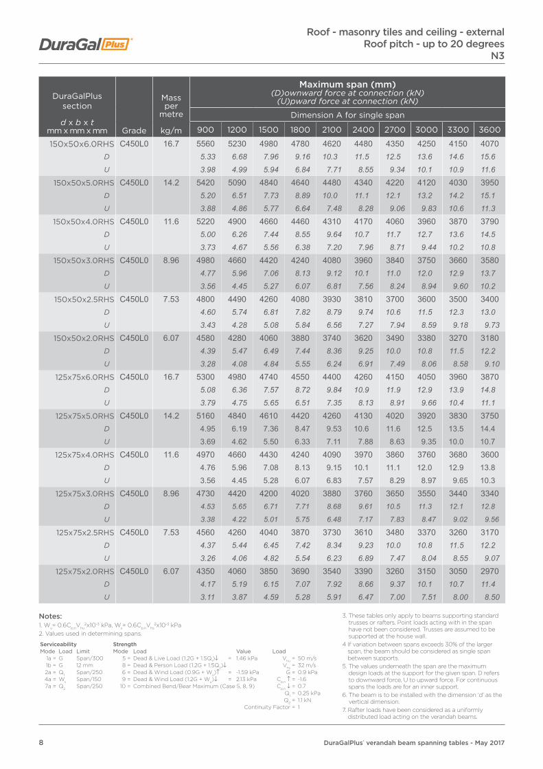
DuraGalPlus section
d x b x tmm x mm x mm Grade
Mass per
metre
kg/m
Maximum span (mm)(D)ownward force at connection (kN)
(U)pward force at connection (kN)
Dimension A for single span
900 1200 1500 1800 2100 2400 2700 3000 3300 3600
150x50x6.0RHS C450L0 16.7 5560 5230 4980 4780 4620 4480 4350 4250 4150 4070D 5.33 6.68 7.96 9.16 10.3 11.5 12.5 13.6 14.6 15.6U 3.98 4.99 5.94 6.84 7.71 8.55 9.34 10.1 10.9 11.6
150x50x5.0RHS C450L0 14.2 5420 5090 4840 4640 4480 4340 4220 4120 4030 3950D 5.20 6.51 7.73 8.89 10.0 11.1 12.1 13.2 14.2 15.1U 3.88 4.86 5.77 6.64 7.48 8.28 9.06 9.83 10.6 11.3
150x50x4.0RHS C450L0 11.6 5220 4900 4660 4460 4310 4170 4060 3960 3870 3790D 5.00 6.26 7.44 8.55 9.64 10.7 11.7 12.7 13.6 14.5U 3.73 4.67 5.56 6.38 7.20 7.96 8.71 9.44 10.2 10.8
150x50x3.0RHS C450L0 8.96 4980 4660 4420 4240 4080 3960 3840 3750 3660 3580D 4.77 5.96 7.06 8.13 9.12 10.1 11.0 12.0 12.9 13.7U 3.56 4.45 5.27 6.07 6.81 7.56 8.24 8.94 9.60 10.2
150x50x2.5RHS C450L0 7.53 4800 4490 4260 4080 3930 3810 3700 3600 3500 3400D 4.60 5.74 6.81 7.82 8.79 9.74 10.6 11.5 12.3 13.0U 3.43 4.28 5.08 5.84 6.56 7.27 7.94 8.59 9.18 9.73
150x50x2.0RHS C450L0 6.07 4580 4280 4060 3880 3740 3620 3490 3380 3270 3180D 4.39 5.47 6.49 7.44 8.36 9.25 10.0 10.8 11.5 12.2U 3.28 4.08 4.84 5.55 6.24 6.91 7.49 8.06 8.58 9.10
125x75x6.0RHS C450L0 16.7 5300 4980 4740 4550 4400 4260 4150 4050 3960 3870D 5.08 6.36 7.57 8.72 9.84 10.9 11.9 12.9 13.9 14.8U 3.79 4.75 5.65 6.51 7.35 8.13 8.91 9.66 10.4 11.1
125x75x5.0RHS C450L0 14.2 5160 4840 4610 4420 4260 4130 4020 3920 3830 3750D 4.95 6.19 7.36 8.47 9.53 10.6 11.6 12.5 13.5 14.4U 3.69 4.62 5.50 6.33 7.11 7.88 8.63 9.35 10.0 10.7
125x75x4.0RHS C450L0 11.6 4970 4660 4430 4240 4090 3970 3860 3760 3680 3600D 4.76 5.96 7.08 8.13 9.15 10.1 11.1 12.0 12.9 13.8U 3.56 4.45 5.28 6.07 6.83 7.57 8.29 8.97 9.65 10.3
125x75x3.0RHS C450L0 8.96 4730 4420 4200 4020 3880 3760 3650 3550 3440 3340D 4.53 5.65 6.71 7.71 8.68 9.61 10.5 11.3 12.1 12.8
U 3.38 4.22 5.01 5.75 6.48 7.17 7.83 8.47 9.02 9.56
125x75x2.5RHS C450L0 7.53 4560 4260 4040 3870 3730 3610 3480 3370 3260 3170D 4.37 5.44 6.45 7.42 8.34 9.23 10.0 10.8 11.5 12.2U 3.26 4.06 4.82 5.54 6.23 6.89 7.47 8.04 8.55 9.07
125x75x2.0RHS C450L0 6.07 4350 4060 3850 3690 3540 3390 3260 3150 3050 2970D 4.17 5.19 6.15 7.07 7.92 8.66 9.37 10.1 10.7 11.4U 3.11 3.87 4.59 5.28 5.91 6.47 7.00 7.51 8.00 8.50
Roof - masonry tiles and ceiling - externalRoof pitch - up to 20 degrees
N3
Notes:1. Wu= 0.6Cp,nVhu
2x10⁻³ kPa, Ws= 0.6Cp,nVhs2x10-3 kPa
2. Values used in determining spans.
Serviceability StrengthMode Load Limit Mode Load Value Load
1a = G Span/300 5 = Dead & Live Load (1.2G + 1.5Q1)↓ = 1.46 kPa Vhu = 50 m/s1b = G 12 mm 8 = Dead & Person Load (1.2G + 1.5Q2)↓ Vhs = 32 m/s2a = Q1 Span/250 6 = Dead & Wind Load (0.9G + Wu)↑ = -1.59 kPa G = 0.9 kPa4a = Ws Span/150 9 = Dead & Wind Load (1.2G + Wu)↓ = 2.13 kPa Cp,n ↑ = -1.67a = Q2 Span/250 10 = Combined Bend/Bear Maximum (Case 5, 8, 9) Cp,n ↓ = 0.7
Q1 = 0.25 kPaQ2 = 1.1 kN
Continuity Factor = 1
3. These tables only apply to beams supporting standard trusses or rafters. Point loads acting with in the span have not been considered. Trusses are assumed to be supported at the house wall.
4 If variation between spans exceeds 30% of the larger span, the beam should be considered as single span between supports.
5. The values underneath the span are the maximum design loads at the support for the given span. D refers to downward force, U to upward force. For continuous spans the loads are for an inner support.
6. The beam is to be installed with the dimension ‘d’ as the vertical dimension.
7. Rafter loads have been considered as a uniformly distributed load acting on the verandah beams.

9DuraGalPlus® verandah beam spanning tables - May 2017
DuraGalPlus section
d x b x tmm x mm x mm Grade
Mass per
metre
kg/m
Maximum span (mm)(D)ownward force at connection (kN)
(U)pward force at connection (kN)
Dimension A for single span
900 1200 1500 1800 2100 2400 2700 3000 3300 3600
100x50x5.0RHS C450L0 10.3 4190 3930 3730 3570 3400 3260 3140 3030 2940 2860D 4.02 5.02 5.96 6.84 7.60 8.33 9.03 9.68 10.3 11.0U 3.00 3.75 4.45 5.11 5.68 6.22 6.74 7.23 7.71 8.19
100x50x4.0RHS C450L0 8.49 4050 3790 3600 3400 3240 3100 2990 2890 2800 2720D 3.88 4.84 5.75 6.52 7.25 7.92 8.60 9.23 9.84 10.4U 2.90 3.62 4.29 4.87 5.41 5.91 6.42 6.89 7.35 7.78
100x50x3.5RHS C450L0 7.53 3960 3710 3490 3290 3130 3000 2890 2790 2710 2630D 3.80 4.74 5.58 6.31 7.00 7.67 8.31 8.91 9.52 10.1U 2.83 3.54 4.16 4.71 5.23 5.72 6.20 6.65 7.11 7.53
100x50x3.0RHS C450L0 6.6 3870 3620 3380 3190 3030 2900 2800 2700 2620 2550D 3.71 4.63 5.40 6.12 6.78 7.41 8.05 8.63 9.21 9.78U 2.77 3.45 4.03 4.56 5.06 5.53 6.01 6.44 6.87 7.30
100x50x2.5RHS C450L0 5.56 3730 3450 3220 3030 2890 2760 2660 2570 2490 2420D 3.58 4.41 5.14 5.81 6.46 7.05 7.65 8.21 8.75 9.28U 2.67 3.29 3.84 4.34 4.82 5.27 5.71 6.13 6.53 6.93
100x50x2.0RHS C450L0 4.50 3560 3240 3020 2850 2710 2590 2490 2410 2340 2270D 3.41 4.14 4.82 5.46 6.06 6.62 7.16 7.70 8.22 8.70U 2.55 3.09 3.60 4.08 4.52 4.94 5.34 5.75 6.14 6.50
100x50x1.6RHS C450L0 3.64 3340 3040 2830 2670 2540 2430 2330 2260 2190 2120D 3.20 3.89 4.52 5.12 5.68 6.21 6.70 7.22 7.70 8.13U 2.39 2.90 3.37 3.82 4.24 4.64 5.00 5.39 5.75 6.07
100x100x3.0SHS C450L0 8.96 4370 4090 3880 3720 3580 3430 3300 3190 3090 3010D 4.19 5.23 6.20 7.13 8.01 8.77 9.49 10.2 10.9 11.5U 3.13 3.90 4.63 5.32 5.98 6.54 7.08 7.61 8.11 8.61
100x100x2.5SHS C450L0 7.53 4210 3940 3740 3570 3400 3260 3130 3030 2940 2860D 4.04 5.04 5.97 6.84 7.60 8.33 9.00 9.68 10.3 11.0U 3.01 3.76 4.46 5.11 5.68 6.22 6.72 7.23 7.71 8.19
100x100x2.0SHS C450L0 6.07 4020 3760 3550 3350 3180 3050 2940 2840 2750 2670D 3.85 4.81 5.67 6.42 7.11 7.80 8.45 9.07 9.66 10.2U 2.88 3.59 4.23 4.79 5.31 5.82 6.31 6.77 7.21 7.64
90x90x2.0SHS C450L0 5.45 3710 3420 3190 3010 2860 2740 2640 2550 2470 2400D 3.56 4.37 5.10 5.77 6.40 7.00 7.59 8.15 8.68 9.20U 2.65 3.26 3.80 4.31 4.77 5.23 5.67 6.08 6.48 6.87
Roof - masonry tiles and ceiling - externalRoof pitch - up to 20 degreesN3
Notes:1. Wu= 0.6Cp,nVhu
2x10⁻³ kPa, Ws= 0.6Cp,nVhs2x10-3 kPa
2. Values used in determining spans.
Serviceability StrengthMode Load Limit Mode Load Value Load
1a = G Span/300 5 = Dead & Live Load (1.2G + 1.5Q1)↓ = 1.46 kPa Vhu = 50 m/s1b = G 12 mm 8 = Dead & Person Load (1.2G + 1.5Q2)↓ Vhs = 32 m/s2a = Q1 Span/250 6 = Dead & Wind Load (0.9G + Wu)↑ = -1.59 kPa G = 0.9 kPa4a = Ws Span/150 9 = Dead & Wind Load (1.2G + Wu)↓ = 2.13 kPa Cp,n ↑ = -1.67a = Q2 Span/250 10 = Combined Bend/Bear Maximum (Case 5, 8, 9) Cp,n ↓ = 0.7
Q1 = 0.25 kPaQ2 = 1.1 kN
Continuity Factor = 1
3. These tables only apply to beams supporting standard trusses or rafters. Point loads acting with in the span have not been considered. Trusses are assumed to be supported at the house wall.
4 If variation between spans exceeds 30% of the larger span, the beam should be considered as single span between supports.
5. The values underneath the span are the maximum design loads at the support for the given span. D refers to downward force, U to upward force. For continuous spans the loads are for an inner support.
6. The beam is to be installed with the dimension ‘d’ as the vertical dimension.
7. Rafter loads have been considered as a uniformly distributed load acting on the verandah beams.

10 DuraGalPlus® verandah beam spanning tables - May 2017
DuraGalPlus section
d x b x tmm x mm x mm Grade
Mass per
metre
kg/m
Maximum span (mm)(D)ownward force at connection (kN)
(U)pward force at connection (kN)
Dimension A for continuous span
900 1200 1500 1800 2100 2400 2700 3000 3300 3600
150x50x6.0RHS C450L0 16.7 6930 6520 6210 5960 5750 5580 5420 5290 5170 5070D 16.6 20.8 24.8 28.6 32.1 35.7 39.0 42.3 45.4 48.6U 12.4 15.6 18.5 21.3 24.0 26.6 29.1 31.5 33.9 36.3
150x50x5.0RHS C450L0 14.2 6750 6340 6030 5790 5580 5410 5260 5130 5020 4910D 16.2 20.3 24.1 27.7 31.2 34.6 37.8 41.0 44.1 47.1U 12.1 15.1 18.0 20.7 23.3 25.8 28.2 30.6 32.9 35.1
150x50x4.0RHS C450L0 11.6 6510 6110 5800 5560 5360 5200 5050 4930 4820 4720D 15.6 19.5 23.2 26.6 30.0 33.2 36.3 39.4 42.3 45.2U 11.6 14.6 17.3 19.9 22.4 24.8 27.1 29.4 31.6 33.8
150x50x3.0RHS C450L0 8.96 6200 5800 5510 5280 5090 4760 4450 4180 3950 3750D 14.9 18.5 22.0 25.3 28.5 30.4 32.0 33.4 34.7 35.9U 11.1 13.8 16.4 18.9 21.2 22.7 23.9 24.9 25.9 26.8
150x50x2.5RHS C450L0 7.53 5980 5590 5270 4730 4310 3960 3680 3440 3240 3060D 14.3 17.9 21.0 22.7 24.1 25.3 26.5 27.5 28.5 29.3U 10.7 13.3 15.7 16.9 18.0 18.9 19.7 20.5 21.3 21.9
150x50x2.0RHS C450L0 6.07 5420 4520 3910 3460 3120 2840 2610 2420 2260 2120D 13.0 14.4 15.6 16.6 17.4 18.1 18.8 19.3 19.9 20.3U 9.70 10.8 11.7 12.4 13.0 13.5 14.0 14.4 14.8 15.2
125x75x6.0RHS C450L0 16.7 6600 6210 5910 5670 5480 5310 5170 5040 4930 4830D 15.8 19.8 23.6 27.2 30.6 33.9 37.2 40.3 43.3 46.3U 11.8 14.8 17.6 20.3 22.9 25.3 27.7 30.1 32.3 34.6
125x75x5.0RHS C450L0 14.2 6420 6030 5740 5510 5310 5150 5010 4880 4770 4680D 15.4 19.3 22.9 26.4 29.7 32.9 36.0 39.0 41.9 44.9U 11.5 14.4 17.1 19.7 22.2 24.6 26.9 29.1 31.3 33.5
125x75x4.0RHS C450L0 11.6 6190 5800 5520 5290 5100 4940 4800 4690 4580 4480D 14.8 18.5 22.0 25.4 28.5 31.6 34.5 37.5 40.2 42.9U 11.1 13.8 16.5 18.9 21.3 23.6 25.8 28.0 30.0 32.1
125x75x3.0RHS C450L0 8.96 5890 5510 5230 5010 4830 4680 4420 4170 3950 3760D 14.1 17.6 20.9 24.0 27.0 29.9 31.8 33.3 34.7 36.0
U 10.5 13.1 15.6 17.9 20.2 22.3 23.7 24.9 25.9 26.9
125x75x2.5RHS C450L0 7.53 5680 5310 5030 4540 4150 3840 3580 3370 3180 3020D 13.6 17.0 20.1 21.8 23.2 24.5 25.7 26.9 27.9 28.9U 10.2 12.7 15.0 16.2 17.3 18.3 19.2 20.1 20.9 21.6
125x75x2.0RHS C450L0 6.07 5230 4420 3860 3450 3130 2880 2670 2490 2330 2200D 12.5 14.1 15.4 16.5 17.5 18.4 19.2 19.9 20.5 21.1U 9.36 10.5 11.5 12.3 13.1 13.7 14.3 14.8 15.3 15.7
Roof - masonry tiles and ceiling - externalRoof pitch - up to 20 degrees
N3
Notes:1. Wu= 0.6Cp,nVhu
2x10⁻³ kPa, Ws= 0.6Cp,nVhs2x10-3 kPa
2. Values used in determining spans.
Serviceability StrengthMode Load Limit Mode Load Value Load
1a = G Span/300 5 = Dead & Live Load (1.2G + 1.5Q1)↓ = 1.46 kPa Vhu = 50 m/s1b = G 12 mm 8 = Dead & Person Load (1.2G + 1.5Q2)↓ Vhs = 32 m/s2a = Q1 Span/250 6 = Dead & Wind Load (0.9G + Wu)↑ = -1.59 kPa G = 0.9 kPa4a = Ws Span/150 9 = Dead & Wind Load (1.2G + Wu)↓ = 2.13 kPa Cp,n ↑ = -1.67a = Q2 Span/250 10 = Combined Bend/Bear Maximum (Case 5, 8, 9) Cp,n ↓ = 0.7
Q1 = 0.25 kPaQ2 = 1.1 kN
Continuity Factor = 1
3. These tables only apply to beams supporting standard trusses or rafters. Point loads acting with in the span have not been considered. Trusses are assumed to be supported at the house wall.
4 If variation between spans exceeds 30% of the larger span, the beam should be considered as single span between supports.
5. The values underneath the span are the maximum design loads at the support for the given span. D refers to downward force, U to upward force. For continuous spans the loads are for an inner support.
6. The beam is to be installed with the dimension ‘d’ as the vertical dimension.
7. Rafter loads have been considered as a uniformly distributed load acting on the verandah beams.
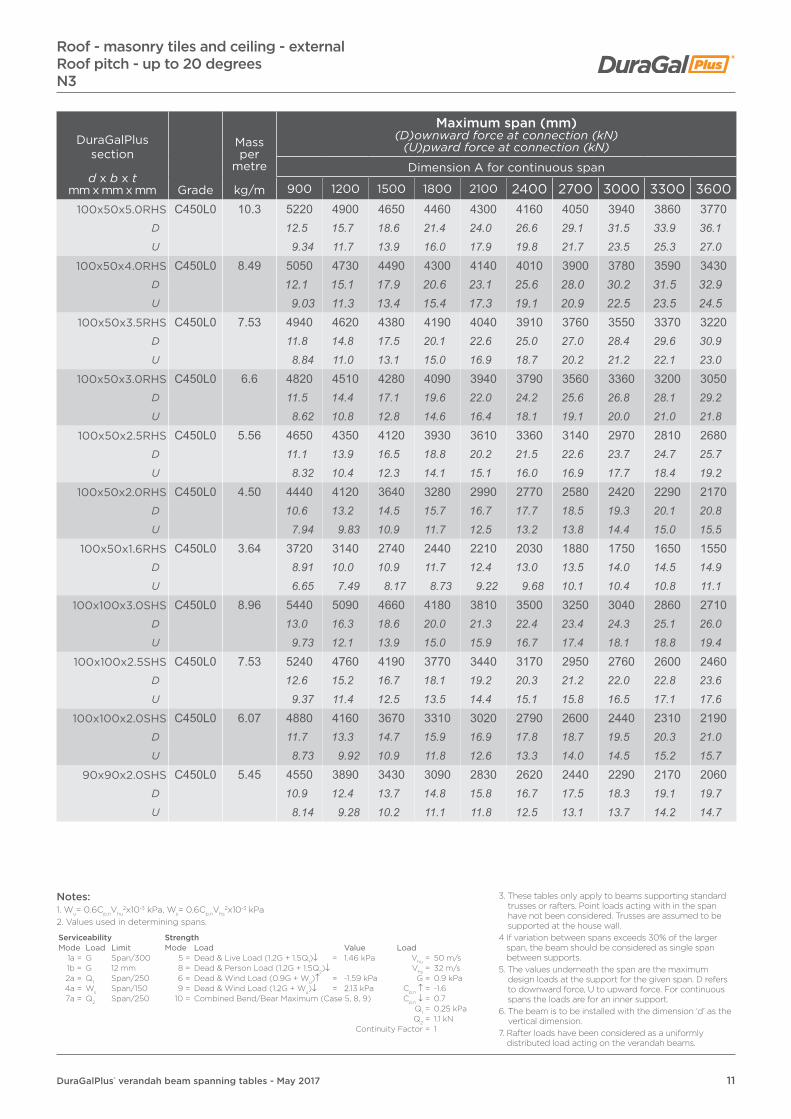
11DuraGalPlus® verandah beam spanning tables - May 2017
DuraGalPlus section
d x b x tmm x mm x mm Grade
Mass per
metre
kg/m
Maximum span (mm)(D)ownward force at connection (kN)
(U)pward force at connection (kN)
Dimension A for continuous span
900 1200 1500 1800 2100 2400 2700 3000 3300 3600100x50x5.0RHS C450L0 10.3 5220 4900 4650 4460 4300 4160 4050 3940 3860 3770
D 12.5 15.7 18.6 21.4 24.0 26.6 29.1 31.5 33.9 36.1U 9.34 11.7 13.9 16.0 17.9 19.8 21.7 23.5 25.3 27.0
100x50x4.0RHS C450L0 8.49 5050 4730 4490 4300 4140 4010 3900 3780 3590 3430D 12.1 15.1 17.9 20.6 23.1 25.6 28.0 30.2 31.5 32.9U 9.03 11.3 13.4 15.4 17.3 19.1 20.9 22.5 23.5 24.5
100x50x3.5RHS C450L0 7.53 4940 4620 4380 4190 4040 3910 3760 3550 3370 3220D 11.8 14.8 17.5 20.1 22.6 25.0 27.0 28.4 29.6 30.9U 8.84 11.0 13.1 15.0 16.9 18.7 20.2 21.2 22.1 23.0
100x50x3.0RHS C450L0 6.6 4820 4510 4280 4090 3940 3790 3560 3360 3200 3050D 11.5 14.4 17.1 19.6 22.0 24.2 25.6 26.8 28.1 29.2U 8.62 10.8 12.8 14.6 16.4 18.1 19.1 20.0 21.0 21.8
100x50x2.5RHS C450L0 5.56 4650 4350 4120 3930 3610 3360 3140 2970 2810 2680D 11.1 13.9 16.5 18.8 20.2 21.5 22.6 23.7 24.7 25.7U 8.32 10.4 12.3 14.1 15.1 16.0 16.9 17.7 18.4 19.2
100x50x2.0RHS C450L0 4.50 4440 4120 3640 3280 2990 2770 2580 2420 2290 2170D 10.6 13.2 14.5 15.7 16.7 17.7 18.5 19.3 20.1 20.8U 7.94 9.83 10.9 11.7 12.5 13.2 13.8 14.4 15.0 15.5
100x50x1.6RHS C450L0 3.64 3720 3140 2740 2440 2210 2030 1880 1750 1650 1550D 8.91 10.0 10.9 11.7 12.4 13.0 13.5 14.0 14.5 14.9U 6.65 7.49 8.17 8.73 9.22 9.68 10.1 10.4 10.8 11.1
100x100x3.0SHS C450L0 8.96 5440 5090 4660 4180 3810 3500 3250 3040 2860 2710D 13.0 16.3 18.6 20.0 21.3 22.4 23.4 24.3 25.1 26.0U 9.73 12.1 13.9 15.0 15.9 16.7 17.4 18.1 18.8 19.4
100x100x2.5SHS C450L0 7.53 5240 4760 4190 3770 3440 3170 2950 2760 2600 2460D 12.6 15.2 16.7 18.1 19.2 20.3 21.2 22.0 22.8 23.6U 9.37 11.4 12.5 13.5 14.4 15.1 15.8 16.5 17.1 17.6
100x100x2.0SHS C450L0 6.07 4880 4160 3670 3310 3020 2790 2600 2440 2310 2190D 11.7 13.3 14.7 15.9 16.9 17.8 18.7 19.5 20.3 21.0U 8.73 9.92 10.9 11.8 12.6 13.3 14.0 14.5 15.2 15.7
90x90x2.0SHS C450L0 5.45 4550 3890 3430 3090 2830 2620 2440 2290 2170 2060D 10.9 12.4 13.7 14.8 15.8 16.7 17.5 18.3 19.1 19.7U 8.14 9.28 10.2 11.1 11.8 12.5 13.1 13.7 14.2 14.7
Roof - masonry tiles and ceiling - externalRoof pitch - up to 20 degreesN3
Notes:1. Wu= 0.6Cp,nVhu
2x10⁻³ kPa, Ws= 0.6Cp,nVhs2x10-3 kPa
2. Values used in determining spans.
Serviceability StrengthMode Load Limit Mode Load Value Load
1a = G Span/300 5 = Dead & Live Load (1.2G + 1.5Q1)↓ = 1.46 kPa Vhu = 50 m/s1b = G 12 mm 8 = Dead & Person Load (1.2G + 1.5Q2)↓ Vhs = 32 m/s2a = Q1 Span/250 6 = Dead & Wind Load (0.9G + Wu)↑ = -1.59 kPa G = 0.9 kPa4a = Ws Span/150 9 = Dead & Wind Load (1.2G + Wu)↓ = 2.13 kPa Cp,n ↑ = -1.67a = Q2 Span/250 10 = Combined Bend/Bear Maximum (Case 5, 8, 9) Cp,n ↓ = 0.7
Q1 = 0.25 kPaQ2 = 1.1 kN
Continuity Factor = 1
3. These tables only apply to beams supporting standard trusses or rafters. Point loads acting with in the span have not been considered. Trusses are assumed to be supported at the house wall.
4 If variation between spans exceeds 30% of the larger span, the beam should be considered as single span between supports.
5. The values underneath the span are the maximum design loads at the support for the given span. D refers to downward force, U to upward force. For continuous spans the loads are for an inner support.
6. The beam is to be installed with the dimension ‘d’ as the vertical dimension.
7. Rafter loads have been considered as a uniformly distributed load acting on the verandah beams.
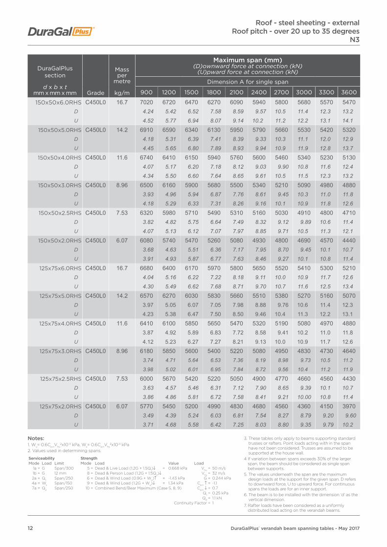
12 DuraGalPlus® verandah beam spanning tables - May 2017
DuraGalPlus section
d x b x tmm x mm x mm Grade
Mass per
metre
kg/m
Maximum span (mm)(D)ownward force at connection (kN)
(U)pward force at connection (kN)
Dimension A for single span
900 1200 1500 1800 2100 2400 2700 3000 3300 3600
150x50x6.0RHS C450L0 16.7 7020 6720 6470 6270 6090 5940 5800 5680 5570 5470D 4.24 5.42 6.52 7.58 8.59 9.57 10.5 11.4 12.3 13.2U 4.52 5.77 6.94 8.07 9.14 10.2 11.2 12.2 13.1 14.1
150x50x5.0RHS C450L0 14.2 6910 6590 6340 6130 5950 5790 5660 5530 5420 5320D 4.18 5.31 6.39 7.41 8.39 9.33 10.3 11.1 12.0 12.9U 4.45 5.65 6.80 7.89 8.93 9.94 10.9 11.9 12.8 13.7
150x50x4.0RHS C450L0 11.6 6740 6410 6150 5940 5760 5600 5460 5340 5230 5130D 4.07 5.17 6.20 7.18 8.12 9.03 9.90 10.8 11.6 12.4U 4.34 5.50 6.60 7.64 8.65 9.61 10.5 11.5 12.3 13.2
150x50x3.0RHS C450L0 8.96 6500 6160 5900 5680 5500 5340 5210 5090 4980 4880D 3.93 4.96 5.94 6.87 7.76 8.61 9.45 10.3 11.0 11.8U 4.18 5.29 6.33 7.31 8.26 9.16 10.1 10.9 11.8 12.6
150x50x2.5RHS C450L0 7.53 6320 5980 5710 5490 5310 5160 5030 4910 4800 4710D 3.82 4.82 5.75 6.64 7.49 8.32 9.12 9.89 10.6 11.4U 4.07 5.13 6.12 7.07 7.97 8.85 9.71 10.5 11.3 12.1
150x50x2.0RHS C450L0 6.07 6080 5740 5470 5260 5080 4930 4800 4690 4570 4440D 3.68 4.63 5.51 6.36 7.17 7.95 8.70 9.45 10.1 10.7U 3.91 4.93 5.87 6.77 7.63 8.46 9.27 10.1 10.8 11.4
125x75x6.0RHS C450L0 16.7 6680 6400 6170 5970 5800 5650 5520 5410 5300 5210D 4.04 5.16 6.22 7.22 8.18 9.11 10.0 10.9 11.7 12.6U 4.30 5.49 6.62 7.68 8.71 9.70 10.7 11.6 12.5 13.4
125x75x5.0RHS C450L0 14.2 6570 6270 6030 5830 5660 5510 5380 5270 5160 5070D 3.97 5.05 6.07 7.05 7.98 8.88 9.76 10.6 11.4 12.3U 4.23 5.38 6.47 7.50 8.50 9.46 10.4 11.3 12.2 13.1
125x75x4.0RHS C450L0 11.6 6410 6100 5850 5650 5470 5320 5190 5080 4970 4880D 3.87 4.92 5.89 6.83 7.72 8.58 9.41 10.2 11.0 11.8U 4.12 5.23 6.27 7.27 8.21 9.13 10.0 10.9 11.7 12.6
125x75x3.0RHS C450L0 8.96 6180 5850 5600 5400 5220 5080 4950 4830 4730 4640D 3.74 4.71 5.64 6.53 7.36 8.19 8.98 9.73 10.5 11.2
U 3.98 5.02 6.01 6.95 7.84 8.72 9.56 10.4 11.2 11.9
125x75x2.5RHS C450L0 7.53 6000 5670 5420 5220 5050 4900 4770 4660 4560 4430D 3.63 4.57 5.46 6.31 7.12 7.90 8.65 9.39 10.1 10.7U 3.86 4.86 5.81 6.72 7.58 8.41 9.21 10.00 10.8 11.4
125x75x2.0RHS C450L0 6.07 5770 5450 5200 4990 4830 4680 4560 4360 4150 3970D 3.49 4.39 5.24 6.03 6.81 7.54 8.27 8.79 9.20 9.60U 3.71 4.68 5.58 6.42 7.25 8.03 8.80 9.35 9.79 10.2
Roof - steel sheeting - externalRoof pitch - over 20 up to 35 degrees
N3
Notes:1. Wu= 0.6Cp,nVhu
2x10⁻³ kPa, Ws= 0.6Cp,nVhs2x10-3 kPa
2. Values used in determining spans.
Serviceability StrengthMode Load Limit Mode Load Value Load
1a = G Span/300 5 = Dead & Live Load (1.2G + 1.5Q1)↓ = 0.668 kPa Vhu = 50 m/s1b = G 12 mm 8 = Dead & Person Load (1.2G + 1.5Q2)↓ Vhs = 32 m/s2a = Q1 Span/250 6 = Dead & Wind Load (0.9G + Wu)↑ = -1.43 kPa G = 0.244 kPa4a = Ws Span/150 9 = Dead & Wind Load (1.2G + Wu)↓ = 1.34 kPa Cp,n ↑ = -1.17a = Q2 Span/250 10 = Combined Bend/Bear Maximum (Case 5, 8, 9) Cp,n ↓ = 0.7
Q1 = 0.25 kPaQ2 = 1.1 kN
Continuity Factor = 1
3. These tables only apply to beams supporting standard trusses or rafters. Point loads acting with in the span have not been considered. Trusses are assumed to be supported at the house wall.
4 If variation between spans exceeds 30% of the larger span, the beam should be considered as single span between supports.
5. The values underneath the span are the maximum design loads at the support for the given span. D refers to downward force, U to upward force. For continuous spans the loads are for an inner support.
6. The beam is to be installed with the dimension ‘d’ as the vertical dimension.
7. Rafter loads have been considered as a uniformly distributed load acting on the verandah beams.

13DuraGalPlus® verandah beam spanning tables - May 2017
DuraGalPlus section
d x b x tmm x mm x mm Grade
Mass per
metre
kg/m
Maximum span (mm)(D)ownward force at connection (kN)
(U)pward force at connection (kN)
Dimension A for single span
900 1200 1500 1800 2100 2400 2700 3000 3300 3600
100x50x5.0RHS C450L0 10.3 5440 5170 4950 4780 4630 4500 4390 4260 4120 4010D 3.29 4.17 4.99 5.78 6.53 7.25 7.96 8.58 9.13 9.70U 3.50 4.44 5.31 6.15 6.95 7.72 8.48 9.14 9.72 10.3
100x50x4.0RHS C450L0 8.49 5310 5030 4810 4630 4480 4350 4190 4040 3910 3800D 3.21 4.05 4.85 5.60 6.32 7.01 7.60 8.14 8.67 9.19U 3.42 4.32 5.16 5.96 6.73 7.46 8.09 8.67 9.23 9.78
100x50x3.5RHS C450L0 7.53 5220 4930 4720 4540 4390 4210 4050 3910 3790 3680D 3.16 3.97 4.76 5.49 6.19 6.79 7.34 7.88 8.40 8.90U 3.36 4.23 5.06 5.84 6.59 7.22 7.82 8.39 8.94 9.47
100x50x3.0RHS C450L0 6.6 5120 4840 4620 4440 4250 4070 3910 3770 3660 3550D 3.09 3.90 4.65 5.37 5.99 6.56 7.09 7.60 8.11 8.58U 3.29 4.15 4.96 5.71 6.38 6.98 7.55 8.09 8.64 9.14
100x50x2.5RHS C450L0 5.56 4970 4690 4470 4250 4040 3860 3710 3580 3470 3370D 3.00 3.78 4.50 5.14 5.70 6.22 6.73 7.21 7.69 8.15U 3.20 4.02 4.79 5.47 6.07 6.62 7.16 7.68 8.19 8.67
100x50x2.0RHS C450L0 4.50 4780 4500 4230 3980 3780 3620 3480 3360 3250 3160D 2.89 3.63 4.26 4.81 5.33 5.84 6.31 6.77 7.20 7.64U 3.08 3.86 4.54 5.12 5.68 6.21 6.72 7.21 7.67 8.13
100x50x1.6RHS C450L0 3.64 4590 4260 3960 3720 3540 3380 3250 3080 2940 2810D 2.77 3.43 3.99 4.50 4.99 5.45 5.89 6.21 6.52 6.79U 2.95 3.66 4.25 4.79 5.32 5.80 6.27 6.61 6.94 7.23
100x100x3.0SHS C450L0 8.96 5710 5410 5180 4990 4830 4690 4570 4470 4330 4210D 3.45 4.36 5.22 6.03 6.81 7.56 8.29 9.01 9.60 10.2U 3.67 4.64 5.56 6.42 7.25 8.05 8.82 9.59 10.2 10.8
100x100x2.5SHS C450L0 7.53 5540 5240 5010 4820 4660 4530 4390 4240 4100 3990D 3.35 4.22 5.05 5.83 6.57 7.30 7.96 8.54 9.09 9.65U 3.57 4.50 5.37 6.20 7.00 7.77 8.48 9.10 9.67 10.3
100x100x2.0SHS C450L0 6.07 5340 5030 4800 4620 4460 4250 4000 3790 3620 3460D 3.23 4.05 4.84 5.59 6.29 6.85 7.25 7.64 8.02 8.37U 3.44 4.32 5.15 5.95 6.70 7.29 7.72 8.13 8.54 8.91
90x90x2.0SHS C450L0 5.45 4950 4660 4440 4210 4000 3830 3680 3500 3330 3190D 2.99 3.76 4.47 5.09 5.64 6.17 6.67 7.05 7.38 7.71U 3.19 4.00 4.76 5.42 6.01 6.57 7.10 7.51 7.86 8.21
Roof - steel sheeting - externalRoof pitch - over 20 up to 35 degreesN3
Notes:1. Wu= 0.6Cp,nVhu
2x10⁻³ kPa, Ws= 0.6Cp,nVhs2x10-3 kPa
2. Values used in determining spans.
Serviceability StrengthMode Load Limit Mode Load Value Load
1a = G Span/300 5 = Dead & Live Load (1.2G + 1.5Q1)↓ = 0.668 kPa Vhu = 50 m/s1b = G 12 mm 8 = Dead & Person Load (1.2G + 1.5Q2)↓ Vhs = 32 m/s2a = Q1 Span/250 6 = Dead & Wind Load (0.9G + Wu)↑ = -1.43 kPa G = 0.244 kPa4a = Ws Span/150 9 = Dead & Wind Load (1.2G + Wu)↓ = 1.34 kPa Cp,n ↑ = -1.17a = Q2 Span/250 10 = Combined Bend/Bear Maximum (Case 5, 8, 9) Cp,n ↓ = 0.7
Q1 = 0.25 kPaQ2 = 1.1 kN
Continuity Factor = 1
3. These tables only apply to beams supporting standard trusses or rafters. Point loads acting with in the span have not been considered. Trusses are assumed to be supported at the house wall.
4 If variation between spans exceeds 30% of the larger span, the beam should be considered as single span between supports.
5. The values underneath the span are the maximum design loads at the support for the given span. D refers to downward force, U to upward force. For continuous spans the loads are for an inner support.
6. The beam is to be installed with the dimension ‘d’ as the vertical dimension.
7. Rafter loads have been considered as a uniformly distributed load acting on the verandah beams.

14 DuraGalPlus® verandah beam spanning tables - May 2017
DuraGalPlus section
d x b x tmm x mm x mm Grade
Mass per
metre
kg/m
Maximum span (mm)(D)ownward force at connection (kN)
(U)pward force at connection (kN)
Dimension A for continuous span
900 1200 1500 1800 2100 2400 2700 3000 3300 3600
150x50x6.0RHS C450L0 16.7 8740 8370 8070 7810 7590 7400 7230 7070 6940 6810D 13.2 16.9 20.3 23.6 26.8 29.8 32.8 35.6 38.5 41.2U 14.1 18.0 21.6 25.1 28.5 31.7 34.9 37.9 40.9 43.8
150x50x5.0RHS C450L0 14.2 0 8210 7900 7640 7410 7220 7050 6890 6760 6630D 13.0 16.5 19.9 23.1 26.1 29.1 32.0 34.7 37.5 40.1U 13.8 17.6 21.2 24.6 27.8 31.0 34.0 36.9 39.9 42.7
150x50x4.0RHS C450L0 11.6 8390 7990 7660 7400 7170 6980 6800 6640 6320 6040D 12.7 16.1 19.3 22.4 25.3 28.1 30.8 33.4 35.0 36.5U 13.5 17.1 20.5 23.8 26.9 29.9 32.8 35.6 37.3 38.9
150x50x3.0RHS C450L0 8.96 8100 7680 7350 7080 6640 6170 5780 5450 5160 4910D 12.2 15.5 18.5 21.4 23.4 24.9 26.2 27.5 28.6 29.7U 13.0 16.5 19.7 22.8 24.9 26.5 27.9 29.2 30.4 31.6
150x50x2.5RHS C450L0 7.53 7870 7450 6880 6200 5670 5250 4890 4590 4330 4100D 11.9 15.0 17.3 18.7 20.0 21.2 22.2 23.1 24.0 24.8U 12.7 16.0 18.4 19.9 21.3 22.5 23.6 24.6 25.5 26.4
150x50x2.0RHS C450L0 6.07 7140 6020 5250 4680 4240 3890 3600 3350 3140 2950D 10.8 12.1 13.2 14.1 15.0 15.7 16.3 16.9 17.4 17.8U 11.5 12.9 14.1 15.1 15.9 16.7 17.4 18.0 18.5 19.0
125x75x6.0RHS C450L0 16.7 8330 7970 7680 7440 7230 7040 6880 6740 6610 6490D 12.6 16.1 19.3 22.5 25.5 28.4 31.2 34.0 36.6 39.2U 13.4 17.1 20.6 23.9 27.1 30.2 33.2 36.1 39.0 41.8
125x75x5.0RHS C450L0 14.2 8190 7820 7520 7270 7050 6870 6710 6560 6430 6310D 12.4 15.8 18.9 22.0 24.9 27.7 30.4 33.0 35.6 38.1U 13.2 16.8 20.2 23.4 26.5 29.5 32.4 35.2 37.9 40.6
125x75x4.0RHS C450L0 11.6 7980 7600 7290 7030 6820 6630 6470 6320 6040 5770D 12.1 15.3 18.4 21.2 24.0 26.7 29.3 31.8 33.5 34.9U 12.8 16.3 19.5 22.6 25.6 28.4 31.2 33.9 35.6 37.1
125x75x3.0RHS C450L0 8.96 7690 7290 6980 6720 6510 6070 5700 5380 5110 4870D 11.6 14.7 17.6 20.3 23.0 24.5 25.8 27.1 28.3 29.4
U 12.4 15.6 18.7 21.6 24.4 26.0 27.5 28.9 30.1 31.3
125x75x2.5RHS C450L0 7.53 7470 7070 6480 5870 5390 5000 4680 4410 4170 3970D 11.3 14.2 16.3 17.7 19.0 20.1 21.2 22.2 23.1 24.0U 12.0 15.2 17.4 18.9 20.2 21.5 22.6 23.6 24.6 25.5
125x75x2.0RHS C450L0 6.07 6770 5770 5080 4570 4160 3840 3570 3350 3150 2980D 10.2 11.6 12.8 13.8 14.7 15.5 16.2 16.9 17.5 18.0U 10.9 12.4 13.6 14.7 15.6 16.5 17.2 18.0 18.6 19.2
Roof - steel sheeting - externalRoof pitch - over 20 up to 35 degrees
N3
Notes:1. Wu= 0.6Cp,nVhu
2x10⁻³ kPa, Ws= 0.6Cp,nVhs2x10-3 kPa
2. Values used in determining spans.
Serviceability StrengthMode Load Limit Mode Load Value Load
1a = G Span/300 5 = Dead & Live Load (1.2G + 1.5Q1)↓ = 0.668 kPa Vhu = 50 m/s1b = G 12 mm 8 = Dead & Person Load (1.2G + 1.5Q2)↓ Vhs = 32 m/s2a = Q1 Span/250 6 = Dead & Wind Load (0.9G + Wu)↑ = -1.43 kPa G = 0.244 kPa4a = Ws Span/150 9 = Dead & Wind Load (1.2G + Wu)↓ = 1.34 kPa Cp,n ↑ = -1.17a = Q2 Span/250 10 = Combined Bend/Bear Maximum (Case 5, 8, 9) Cp,n ↓ = 0.7
Q1 = 0.25 kPaQ2 = 1.1 kN
Continuity Factor = 1
3. These tables only apply to beams supporting standard trusses or rafters. Point loads acting with in the span have not been considered. Trusses are assumed to be supported at the house wall.
4 If variation between spans exceeds 30% of the larger span, the beam should be considered as single span between supports.
5. The values underneath the span are the maximum design loads at the support for the given span. D refers to downward force, U to upward force. For continuous spans the loads are for an inner support.
6. The beam is to be installed with the dimension ‘d’ as the vertical dimension.
7. Rafter loads have been considered as a uniformly distributed load acting on the verandah beams.

15DuraGalPlus® verandah beam spanning tables - May 2017
DuraGalPlus section
d x b x tmm x mm x mm Grade
Mass per
metre
kg/m
Maximum span (mm)(D)ownward force at connection (kN)
(U)pward force at connection (kN)
Dimension A for continuous span
900 1200 1500 1800 2100 2400 2700 3000 3300 3600100x50x5.0RHS C450L0 10.3 6780 6440 6170 5950 5760 5600 5460 5340 5230 5050
D 10.2 13.0 15.5 18.0 20.3 22.6 24.8 26.9 29.0 30.5U 10.9 13.8 16.5 19.1 21.6 24.0 26.4 28.6 30.9 32.5
100x50x4.0RHS C450L0 8.49 6610 6270 5990 5770 5580 5430 5290 5070 4830 4620D 9.99 12.6 15.1 17.4 19.7 21.9 24.0 25.5 26.8 27.9U 10.6 13.4 16.1 18.6 20.9 23.3 25.5 27.2 28.5 29.7
100x50x3.5RHS C450L0 7.53 6500 6150 5870 5650 5470 5310 5060 4790 4570 4370D 9.82 12.4 14.8 17.1 19.3 21.4 22.9 24.1 25.3 26.4U 10.5 13.2 15.7 18.2 20.5 22.8 24.4 25.7 27.0 28.1
100x50x3.0RHS C450L0 6.6 6380 6030 5750 5530 5170 4820 4540 4290 4080 3900D 9.64 12.1 14.5 16.7 18.2 19.4 20.6 21.6 22.6 23.6U 10.3 12.9 15.4 17.8 19.4 20.7 21.9 23.0 24.1 25.1
100x50x2.5RHS C450L0 5.56 6200 5840 5520 5020 4630 4310 4050 3820 3630 3460D 9.37 11.8 13.9 15.2 16.3 17.4 18.4 19.2 20.1 20.9U 9.97 12.5 14.8 16.2 17.4 18.5 19.5 20.5 21.4 22.3
100x50x2.0RHS C450L0 4.50 5960 5310 4710 4250 3900 3620 3380 3180 3010 2860D 9.01 10.7 11.9 12.8 13.8 14.6 15.3 16.0 16.7 17.3U 9.59 11.4 12.6 13.7 14.6 15.5 16.3 17.1 17.8 18.4
100x50x1.6RHS C450L0 3.64 4850 4110 3610 3240 2950 2720 2530 2370 2230 2110D 7.33 8.28 9.09 9.79 10.4 11.0 11.5 11.9 12.4 12.8U 7.80 8.82 9.68 10.4 11.1 11.7 12.2 12.7 13.2 13.6
100x100x3.0SHS C450L0 8.96 7110 6740 6070 5480 5010 4630 4320 4060 3830 3630D 10.7 13.6 15.3 16.6 17.7 18.7 19.6 20.5 21.2 21.9U 11.4 14.5 16.3 17.6 18.8 19.9 20.8 21.8 22.6 23.4
100x100x2.5SHS C450L0 7.53 6910 6150 5440 4910 4500 4170 3890 3660 3450 3280D 10.4 12.4 13.7 14.8 15.9 16.8 17.6 18.4 19.1 19.8U 11.1 13.2 14.6 15.8 16.9 17.9 18.8 19.6 20.4 21.1
100x100x2.0SHS C450L0 6.07 6240 5360 4750 4290 3940 3650 3410 3210 3040 2890D 9.43 10.8 12.0 13.0 13.9 14.7 15.5 16.2 16.8 17.5U 10.0 11.5 12.7 13.8 14.8 15.7 16.5 17.2 17.9 18.6
90x90x2.0SHS C450L0 5.45 5810 4990 4430 4010 3680 3410 3190 3010 2850 2710D 8.78 10.1 11.2 12.1 13.0 13.7 14.5 15.2 15.8 16.4U 9.35 10.7 11.9 12.9 13.8 14.6 15.4 16.1 16.8 17.4
Roof - steel sheeting - externalRoof pitch - over 20 up to 35 degreesN3
Notes:1. Wu= 0.6Cp,nVhu
2x10⁻³ kPa, Ws= 0.6Cp,nVhs2x10-3 kPa
2. Values used in determining spans.
Serviceability StrengthMode Load Limit Mode Load Value Load
1a = G Span/300 5 = Dead & Live Load (1.2G + 1.5Q1)↓ = 0.668 kPa Vhu = 50 m/s1b = G 12 mm 8 = Dead & Person Load (1.2G + 1.5Q2)↓ Vhs = 32 m/s2a = Q1 Span/250 6 = Dead & Wind Load (0.9G + Wu)↑ = -1.43 kPa G = 0.244 kPa4a = Ws Span/150 9 = Dead & Wind Load (1.2G + Wu)↓ = 1.34 kPa Cp,n ↑ = -1.17a = Q2 Span/250 10 = Combined Bend/Bear Maximum (Case 5, 8, 9) Cp,n ↓ = 0.7
Q1 = 0.25 kPaQ2 = 1.1 kN
Continuity Factor = 1
3. These tables only apply to beams supporting standard trusses or rafters. Point loads acting with in the span have not been considered. Trusses are assumed to be supported at the house wall.
4 If variation between spans exceeds 30% of the larger span, the beam should be considered as single span between supports.
5. The values underneath the span are the maximum design loads at the support for the given span. D refers to downward force, U to upward force. For continuous spans the loads are for an inner support.
6. The beam is to be installed with the dimension ‘d’ as the vertical dimension.
7. Rafter loads have been considered as a uniformly distributed load acting on the verandah beams.

16 DuraGalPlus® verandah beam spanning tables - May 2017
DuraGalPlus section
d x b x tmm x mm x mm Grade
Mass per
metre
kg/m
Maximum span (mm)(D)ownward force at connection (kN)
(U)pward force at connection (kN)
Dimension A for single span
900 1200 1500 1800 2100 2400 2700 3000 3300 3600
150x50x6.0RHS C450L0 16.7 5560 5230 4980 4780 4620 4480 4350 4250 4150 4070D 5.33 6.68 7.96 9.16 10.3 11.5 12.5 13.6 14.6 15.6U 2.10 2.64 3.14 3.61 4.07 4.52 4.93 5.36 5.75 6.15
150x50x5.0RHS C450L0 14.2 5420 5090 4840 4640 4480 4340 4220 4120 4030 3950D 5.20 6.51 7.73 8.89 10.0 11.1 12.1 13.2 14.2 15.1U 2.05 2.57 3.05 3.51 3.95 4.37 4.79 5.19 5.59 5.97
150x50x4.0RHS C450L0 11.6 5220 4900 4660 4460 4310 4170 4060 3960 3870 3790D 5.00 6.26 7.44 8.55 9.64 10.7 11.7 12.7 13.6 14.5U 1.97 2.47 2.94 3.37 3.80 4.20 4.60 4.99 5.36 5.73
150x50x3.0RHS C450L0 8.96 4980 4660 4420 4240 4080 3960 3840 3750 3660 3580D 4.77 5.96 7.06 8.13 9.12 10.1 11.0 12.0 12.9 13.7U 1.88 2.35 2.78 3.21 3.60 3.99 4.35 4.73 5.07 5.41
150x50x2.5RHS C450L0 7.53 4800 4490 4260 4080 3930 3810 3700 3600 3500 3400D 4.60 5.74 6.81 7.82 8.79 9.74 10.6 11.5 12.3 13.0U 1.81 2.26 2.68 3.08 3.47 3.84 4.20 4.54 4.85 5.14
150x50x2.0RHS C450L0 6.07 4580 4280 4060 3880 3740 3620 3490 3380 3270 3180D 4.39 5.47 6.49 7.44 8.36 9.25 10.0 10.8 11.5 12.2U 1.73 2.16 2.56 2.93 3.30 3.65 3.96 4.26 4.53 4.81
125x75x6.0RHS C450L0 16.7 5300 4980 4740 4550 4400 4260 4150 4050 3960 3870D 5.08 6.36 7.57 8.72 9.84 10.9 11.9 12.9 13.9 14.8U 2.00 2.51 2.99 3.44 3.88 4.29 4.71 5.10 5.49 5.85
125x75x5.0RHS C450L0 14.2 5160 4840 4610 4420 4260 4130 4020 3920 3830 3750D 4.95 6.19 7.36 8.47 9.53 10.6 11.6 12.5 13.5 14.4U 1.95 2.44 2.90 3.34 3.76 4.16 4.56 4.94 5.31 5.67
125x75x4.0RHS C450L0 11.6 4970 4660 4430 4240 4090 3970 3860 3760 3680 3600D 4.76 5.96 7.08 8.13 9.15 10.1 11.1 12.0 12.9 13.8U 1.88 2.35 2.79 3.21 3.61 4.00 4.38 4.74 5.10 5.44
125x75x3.0RHS C450L0 8.96 4730 4420 4200 4020 3880 3760 3650 3550 3440 3340D 4.53 5.65 6.71 7.71 8.68 9.61 10.5 11.3 12.1 12.8
U 1.79 2.23 2.65 3.04 3.42 3.79 4.14 4.47 4.77 5.05
125x75x2.5RHS C450L0 7.53 4560 4260 4040 3870 3730 3610 3480 3370 3260 3170D 4.37 5.44 6.45 7.42 8.34 9.23 10.0 10.8 11.5 12.2U 1.72 2.15 2.55 2.93 3.29 3.64 3.95 4.25 4.52 4.79
125x75x2.0RHS C450L0 6.07 4350 4060 3850 3690 3540 3390 3260 3150 3050 2970D 4.17 5.19 6.15 7.07 7.92 8.66 9.37 10.1 10.7 11.4U 1.64 2.05 2.43 2.79 3.12 3.42 3.70 3.97 4.23 4.49
Roof - masonry tiles and ceiling - externalRoof pitch - over 20 up to 35 degrees
N3
Notes:1. Wu= 0.6Cp,nVhu
2x10⁻³ kPa, Ws= 0.6Cp,nVhs2x10-3 kPa
2. Values used in determining spans.
Serviceability StrengthMode Load Limit Mode Load Value Load
1a = G Span/300 5 = Dead & Live Load (1.2G + 1.5Q1)↓ = 1.46 kPa Vhu = 50 m/s1b = G 12 mm 8 = Dead & Person Load (1.2G + 1.5Q2)↓ Vhs = 32 m/s2a = Q1 Span/250 6 = Dead & Wind Load (0.9G + Wu)↑ = -0.84 kPa G = 0.9 kPa4a = Ws Span/150 9 = Dead & Wind Load (1.2G + Wu)↓ = 2.13 kPa Cp,n ↑ = -1.17a = Q2 Span/250 10 = Combined Bend/Bear Maximum (Case 5, 8, 9) Cp,n ↓ = 0.7
Q1 = 0.25 kPaQ2 = 1.1 kN
Continuity Factor = 1
3. These tables only apply to beams supporting standard trusses or rafters. Point loads acting with in the span have not been considered. Trusses are assumed to be supported at the house wall.
4 If variation between spans exceeds 30% of the larger span, the beam should be considered as single span between supports.
5. The values underneath the span are the maximum design loads at the support for the given span. D refers to downward force, U to upward force. For continuous spans the loads are for an inner support.
6. The beam is to be installed with the dimension ‘d’ as the vertical dimension.
7. Rafter loads have been considered as a uniformly distributed load acting on the verandah beams.
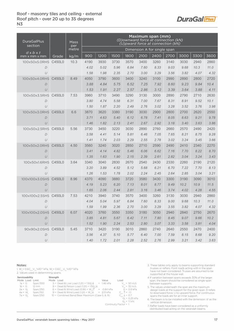
17DuraGalPlus® verandah beam spanning tables - May 2017
DuraGalPlus section
d x b x tmm x mm x mm Grade
Mass per
metre
kg/m
Maximum span (mm)(D)ownward force at connection (kN)
(U)pward force at connection (kN)
Dimension A for single span
900 1200 1500 1800 2100 2400 2700 3000 3300 3600
100x50x5.0RHS C450L0 10.3 4190 3930 3730 3570 3400 3260 3140 3030 2940 2860D 4.02 5.02 5.96 6.84 7.60 8.33 9.03 9.68 10.3 11.0U 1.58 1.98 2.35 2.70 3.00 3.29 3.56 3.82 4.07 4.32
100x50x4.0RHS C450L0 8.49 4050 3790 3600 3400 3240 3100 2990 2890 2800 2720D 3.88 4.84 5.75 6.52 7.25 7.92 8.60 9.23 9.84 10.4U 1.53 1.91 2.27 2.57 2.86 3.12 3.39 3.64 3.88 4.11
100x50x3.5RHS C450L0 7.53 3960 3710 3490 3290 3130 3000 2890 2790 2710 2630D 3.80 4.74 5.58 6.31 7.00 7.67 8.31 8.91 9.52 10.1U 1.50 1.87 2.20 2.49 2.76 3.02 3.28 3.52 3.76 3.98
100x50x3.0RHS C450L0 6.6 3870 3620 3380 3190 3030 2900 2800 2700 2620 2550D 3.71 4.63 5.40 6.12 6.78 7.41 8.05 8.63 9.21 9.78U 1.46 1.82 2.13 2.41 2.67 2.92 3.18 3.40 3.63 3.86
100x50x2.5RHS C450L0 5.56 3730 3450 3220 3030 2890 2760 2660 2570 2490 2420D 3.58 4.41 5.14 5.81 6.46 7.05 7.65 8.21 8.75 9.28U 1.41 1.74 2.03 2.29 2.55 2.78 3.02 3.24 3.45 3.66
100x50x2.0RHS C450L0 4.50 3560 3240 3020 2850 2710 2590 2490 2410 2340 2270D 3.41 4.14 4.82 5.46 6.06 6.62 7.16 7.70 8.22 8.70U 1.35 1.63 1.90 2.15 2.39 2.61 2.82 3.04 3.24 3.43
100x50x1.6RHS C450L0 3.64 3340 3040 2830 2670 2540 2430 2330 2260 2190 2120D 3.20 3.89 4.52 5.12 5.68 6.21 6.70 7.22 7.70 8.13U 1.26 1.53 1.78 2.02 2.24 2.45 2.64 2.85 3.04 3.21
100x100x3.0SHS C450L0 8.96 4370 4090 3880 3720 3580 3430 3300 3190 3090 3010D 4.19 5.23 6.20 7.13 8.01 8.77 9.49 10.2 10.9 11.5U 1.65 2.06 2.44 2.81 3.16 3.46 3.74 4.02 4.28 4.55
100x100x2.5SHS C450L0 7.53 4210 3940 3740 3570 3400 3260 3130 3030 2940 2860D 4.04 5.04 5.97 6.84 7.60 8.33 9.00 9.68 10.3 11.0U 1.59 1.99 2.36 2.70 3.00 3.29 3.55 3.82 4.07 4.32
100x100x2.0SHS C450L0 6.07 4020 3760 3550 3350 3180 3050 2940 2840 2750 2670D 3.85 4.81 5.67 6.42 7.11 7.80 8.45 9.07 9.66 10.2U 1.52 1.90 2.24 2.53 2.80 3.07 3.33 3.58 3.81 4.04
90x90x2.0SHS C450L0 5.45 3710 3420 3190 3010 2860 2740 2640 2550 2470 2400D 3.56 4.37 5.10 5.77 6.40 7.00 7.59 8.15 8.68 9.20U 1.40 1.72 2.01 2.28 2.52 2.76 2.99 3.21 3.42 3.63
Roof - masonry tiles and ceiling - externalRoof pitch - over 20 up to 35 degreesN3
Notes:1. Wu= 0.6Cp,nVhu
2x10⁻³ kPa, Ws= 0.6Cp,nVhs2x10-3 kPa
2. Values used in determining spans.
Serviceability StrengthMode Load Limit Mode Load Value Load
1a = G Span/300 5 = Dead & Live Load (1.2G + 1.5Q1)↓ = 1.46 kPa Vhu = 50 m/s1b = G 12 mm 8 = Dead & Person Load (1.2G + 1.5Q2)↓ Vhs = 32 m/s2a = Q1 Span/250 6 = Dead & Wind Load (0.9G + Wu)↑ = -0.84 kPa G = 0.9 kPa4a = Ws Span/150 9 = Dead & Wind Load (1.2G + Wu)↓ = 2.13 kPa Cp,n ↑ = -1.17a = Q2 Span/250 10 = Combined Bend/Bear Maximum (Case 5, 8, 9) Cp,n ↓ = 0.7
Q1 = 0.25 kPaQ2 = 1.1 kN
Continuity Factor = 1
3. These tables only apply to beams supporting standard trusses or rafters. Point loads acting with in the span have not been considered. Trusses are assumed to be supported at the house wall.
4 If variation between spans exceeds 30% of the larger span, the beam should be considered as single span between supports.
5. The values underneath the span are the maximum design loads at the support for the given span. D refers to downward force, U to upward force. For continuous spans the loads are for an inner support.
6. The beam is to be installed with the dimension ‘d’ as the vertical dimension.
7. Rafter loads have been considered as a uniformly distributed load acting on the verandah beams.

18 DuraGalPlus® verandah beam spanning tables - May 2017
DuraGalPlus section
d x b x tmm x mm x mm Grade
Mass per
metre
kg/m
Maximum span (mm)(D)ownward force at connection (kN)
(U)pward force at connection (kN)
Dimension A for continuous span
900 1200 1500 1800 2100 2400 2700 3000 3300 3600
150x50x6.0RHS C450L0 16.7 6930 6520 6210 5960 5750 5580 5420 5290 5170 5070D 16.6 20.8 24.8 28.6 32.1 35.7 39.0 42.3 45.4 48.6U 6.55 8.22 9.78 11.3 12.7 14.1 15.4 16.7 17.9 19.2
150x50x5.0RHS C450L0 14.2 6750 6340 6030 5790 5580 5410 5260 5130 5020 4910D 16.2 20.3 24.1 27.7 31.2 34.6 37.8 41.0 44.1 47.1U 6.38 7.99 9.50 10.9 12.3 13.6 14.9 16.2 17.4 18.6
150x50x4.0RHS C450L0 11.6 6510 6110 5800 5560 5360 5200 5050 4930 4820 4720D 15.6 19.5 23.2 26.6 30.0 33.2 36.3 39.4 42.3 45.2U 6.15 7.70 9.14 10.5 11.8 13.1 14.3 15.5 16.7 17.8
150x50x3.0RHS C450L0 8.96 6200 5800 5510 5280 5090 4760 4450 4180 3950 3750D 14.9 18.5 22.0 25.3 28.5 30.4 32.0 33.4 34.7 35.9U 5.86 7.31 8.68 9.98 11.2 12.0 12.6 13.2 13.7 14.2
150x50x2.5RHS C450L0 7.53 5980 5590 5270 4730 4310 3960 3680 3440 3240 3060D 14.3 17.9 21.0 22.7 24.1 25.3 26.5 27.5 28.5 29.3U 5.65 7.04 8.30 8.94 9.50 9.98 10.4 10.8 11.2 11.6
150x50x2.0RHS C450L0 6.07 5420 4520 3910 3460 3120 2840 2610 2420 2260 2120D 13.0 14.4 15.6 16.6 17.4 18.1 18.8 19.3 19.9 20.3U 5.12 5.70 6.16 6.54 6.88 7.16 7.40 7.62 7.83 8.01
125x75x6.0RHS C450L0 16.7 6600 6210 5910 5670 5480 5310 5170 5040 4930 4830D 15.8 19.8 23.6 27.2 30.6 33.9 37.2 40.3 43.3 46.3U 6.24 7.82 9.31 10.7 12.1 13.4 14.7 15.9 17.1 18.3
125x75x5.0RHS C450L0 14.2 6420 6030 5740 5510 5310 5150 5010 4880 4770 4680D 15.4 19.3 22.9 26.4 29.7 32.9 36.0 39.0 41.9 44.9U 6.07 7.60 9.04 10.4 11.7 13.0 14.2 15.4 16.5 17.7
125x75x4.0RHS C450L0 11.6 6190 5800 5520 5290 5100 4940 4800 4690 4580 4480D 14.8 18.5 22.0 25.4 28.5 31.6 34.5 37.5 40.2 42.9U 5.85 7.31 8.69 10.00 11.2 12.4 13.6 14.8 15.9 16.9
125x75x3.0RHS C450L0 8.96 5890 5510 5230 5010 4830 4680 4420 4170 3950 3760D 14.1 17.6 20.9 24.0 27.0 29.9 31.8 33.3 34.7 36.0
U 5.57 6.94 8.24 9.47 10.7 11.8 12.5 13.1 13.7 14.2
125x75x2.5RHS C450L0 7.53 5680 5310 5030 4540 4150 3840 3580 3370 3180 3020D 13.6 17.0 20.1 21.8 23.2 24.5 25.7 26.9 27.9 28.9U 5.37 6.69 7.92 8.58 9.15 9.68 10.1 10.6 11.0 11.4
125x75x2.0RHS C450L0 6.07 5230 4420 3860 3450 3130 2880 2670 2490 2330 2200D 12.5 14.1 15.4 16.5 17.5 18.4 19.2 19.9 20.5 21.1U 4.94 5.57 6.08 6.52 6.90 7.26 7.57 7.84 8.07 8.32
Roof - masonry and ceiling - externalRoof pitch - over 20 up to 35 degrees
N3
Notes:1. Wu= 0.6Cp,nVhu
2x10⁻³ kPa, Ws= 0.6Cp,nVhs2x10-3 kPa
2. Values used in determining spans.
Serviceability StrengthMode Load Limit Mode Load Value Load
1a = G Span/300 5 = Dead & Live Load (1.2G + 1.5Q1)↓ = 1.46 kPa Vhu = 50 m/s1b = G 12 mm 8 = Dead & Person Load (1.2G + 1.5Q2)↓ Vhs = 32 m/s2a = Q1 Span/250 6 = Dead & Wind Load (0.9G + Wu)↑ = -0.84 kPa G = 0.9 kPa4a = Ws Span/150 9 = Dead & Wind Load (1.2G + Wu)↓ = 2.13 kPa Cp,n ↑ = -1.17a = Q2 Span/250 10 = Combined Bend/Bear Maximum (Case 5, 8, 9) Cp,n ↓ = 0.7
Q1 = 0.25 kPaQ2 = 1.1 kN
Continuity Factor = 1
3. These tables only apply to beams supporting standard trusses or rafters. Point loads acting with in the span have not been considered. Trusses are assumed to be supported at the house wall.
4 If variation between spans exceeds 30% of the larger span, the beam should be considered as single span between supports.
5. The values underneath the span are the maximum design loads at the support for the given span. D refers to downward force, U to upward force. For continuous spans the loads are for an inner support.
6. The beam is to be installed with the dimension ‘d’ as the vertical dimension.
7. Rafter loads have been considered as a uniformly distributed load acting on the verandah beams.

19DuraGalPlus® verandah beam spanning tables - May 2017
DuraGalPlus section
d x b x tmm x mm x mm Grade
Mass per
metre
kg/m
Maximum span (mm)(D)ownward force at connection (kN)
(U)pward force at connection (kN)
Dimension A for continuous span
900 1200 1500 1800 2100 2400 2700 3000 3300 3600100x50x5.0RHS C450L0 10.3 5220 4900 4650 4460 4300 4160 4050 3940 3860 3770
D 12.5 15.7 18.6 21.4 24.0 26.6 29.1 31.5 33.9 36.1U 4.93 6.17 7.32 8.43 9.48 10.5 11.5 12.4 13.4 14.3
100x50x4.0RHS C450L0 8.49 5050 4730 4490 4300 4140 4010 3900 3800 3710 3640D 12.1 15.1 17.9 20.6 23.1 25.6 28.0 30.4 32.6 34.9U 4.77 5.96 7.07 8.13 9.13 10.1 11.1 12.0 12.9 13.8
100x50x3.5RHS C450L0 7.53 4940 4620 4380 4190 4040 3910 3800 3710 3620 3530D 11.8 14.8 17.5 20.1 22.6 25.0 27.3 29.6 31.8 33.8U 4.67 5.82 6.90 7.92 8.91 9.85 10.8 11.7 12.5 13.3
100x50x3.0RHS C450L0 6.6 4820 4510 4280 4090 3940 3790 3560 3360 3200 3050D 11.5 14.4 17.1 19.6 22.0 24.2 25.6 26.8 28.1 29.2U 4.55 5.68 6.74 7.73 8.69 9.55 10.1 10.6 11.1 11.5
100x50x2.5RHS C450L0 5.56 4650 4350 4120 3930 3610 3360 3140 2970 2810 2680D 11.1 13.9 16.5 18.8 20.2 21.5 22.6 23.7 24.7 25.7U 4.39 5.48 6.49 7.43 7.96 8.47 8.90 9.36 9.74 10.1
100x50x2.0RHS C450L0 4.50 4440 4120 3640 3280 2990 2770 2580 2420 2290 2170D 10.6 13.2 14.5 15.7 16.7 17.7 18.5 19.3 20.1 20.8U 4.20 5.19 5.73 6.20 6.59 6.98 7.31 7.62 7.93 8.20
100x50x1.6RHS C450L0 3.64 3720 3140 2740 2440 2210 2030 1880 1750 1650 1550D 8.91 10.0 10.9 11.7 12.4 13.0 13.5 14.0 14.5 14.9U 3.52 3.96 4.32 4.61 4.87 5.12 5.33 5.51 5.72 5.86
100x100x3.0SHS C450L0 8.96 5440 5090 4660 4180 3810 3500 3250 3040 2860 2710D 13.0 16.3 18.6 20.0 21.3 22.4 23.4 24.3 25.1 26.0U 5.14 6.41 7.34 7.90 8.40 8.82 9.21 9.58 9.91 10.2
100x100x2.5SHS C450L0 7.53 5240 4760 4190 3770 3440 3170 2950 2760 2600 2460D 12.6 15.2 16.7 18.1 19.2 20.3 21.2 22.0 22.8 23.6U 4.95 6.00 6.60 7.13 7.59 7.99 8.36 8.69 9.01 9.30
100x100x2.0SHS C450L0 6.07 4880 4160 3670 3310 3020 2790 2600 2440 2310 2190D 11.7 13.3 14.7 15.9 16.9 17.8 18.7 19.5 20.3 21.0U 4.61 5.24 5.78 6.26 6.66 7.03 7.37 7.69 8.00 8.28
90x90x2.0SHS C450L0 5.45 4550 3890 3430 3090 2830 2620 2440 2290 2170 2060D 10.9 12.4 13.7 14.8 15.8 16.7 17.5 18.3 19.1 19.7U 4.30 4.90 5.40 5.84 6.24 6.60 6.92 7.21 7.52 7.79
Roof - masonry and ceiling - externalRoof pitch - over 20 up to 35 degreesN3
Notes:1. Wu= 0.6Cp,nVhu
2x10⁻³ kPa, Ws= 0.6Cp,nVhs2x10-3 kPa
2. Values used in determining spans.
Serviceability StrengthMode Load Limit Mode Load Value Load
1a = G Span/300 5 = Dead & Live Load (1.2G + 1.5Q1)↓ = 1.46 kPa Vhu = 50 m/s1b = G 12 mm 8 = Dead & Person Load (1.2G + 1.5Q2)↓ Vhs = 32 m/s2a = Q1 Span/250 6 = Dead & Wind Load (0.9G + Wu)↑ = -0.84 kPa G = 0.9 kPa4a = Ws Span/150 9 = Dead & Wind Load (1.2G + Wu)↓ = 2.13 kPa Cp,n ↑ = -1.17a = Q2 Span/250 10 = Combined Bend/Bear Maximum (Case 5, 8, 9) Cp,n ↓ = 0.7
Q1 = 0.25 kPaQ2 = 1.1 kN
Continuity Factor = 1
3. These tables only apply to beams supporting standard trusses or rafters. Point loads acting with in the span have not been considered. Trusses are assumed to be supported at the house wall.
4 If variation between spans exceeds 30% of the larger span, the beam should be considered as single span between supports.
5. The values underneath the span are the maximum design loads at the support for the given span. D refers to downward force, U to upward force. For continuous spans the loads are for an inner support.
6. The beam is to be installed with the dimension ‘d’ as the vertical dimension.
7. Rafter loads have been considered as a uniformly distributed load acting on the verandah beams.

20 DuraGalPlus® verandah beam spanning tables - May 2017
DuraGalPlus section
d x b x tmm x mm x mm Grade
Mass per
metre
kg/m
Maximum span (mm)(D)ownward force at connection (kN)
(U)pward force at connection (kN)
Dimension A for single span
900 1200 1500 1800 2100 2400 2700 3000 3300 3600
150x50x6.0RHS C450L0 16.7 7020 6660 6180 5820 5530 5290 5080 4910 4760 4620D 8.33 10.5 12.2 13.8 15.3 16.7 18.1 19.4 20.7 21.9U 10.6 13.4 15.5 17.6 19.5 21.3 23.0 24.7 26.3 27.9
150x50x5.0RHS C450L0 14.2 6910 6380 5920 5570 5290 5060 4870 4700 4550 4420D 8.20 10.1 11.7 13.2 14.7 16.0 17.3 18.6 19.8 21.0U 10.4 12.8 14.9 16.8 18.6 20.4 22.0 23.6 25.2 26.7
150x50x4.0RHS C450L0 11.6 6630 6020 5590 5260 5000 4780 4600 4440 4300 4180D 7.87 9.53 11.1 12.5 13.8 15.1 16.4 17.6 18.7 19.8U 10.0 12.1 14.1 15.9 17.6 19.2 20.8 22.3 23.8 25.2
150x50x3.0RHS C450L0 8.96 6150 5590 5190 4880 4640 4440 4260 4090 3900 3730D 7.30 8.85 10.3 11.6 12.8 14.1 15.2 16.2 17.0 17.7U 9.28 11.2 13.0 14.7 16.3 17.9 19.3 20.6 21.6 22.5
150x50x2.5RHS C450L0 7.53 5830 5300 4920 4630 4390 4200 3960 3760 3580 3430D 6.92 8.39 9.73 11.0 12.2 13.3 14.1 14.9 15.6 16.3U 8.79 10.7 12.4 14.0 15.5 16.9 17.9 18.9 19.8 20.7
150x50x2.0RHS C450L0 6.07 5450 4950 4540 4140 3830 3580 3380 3200 3050 2920D 6.47 7.83 8.98 9.83 10.6 11.3 12.0 12.7 13.3 13.9U 8.22 9.96 11.4 12.5 13.5 14.4 15.3 16.1 16.9 17.6
125x75x6.0RHS C450L0 16.7 6680 6240 5790 5450 5180 4950 4760 4600 4460 4330D 7.93 9.87 11.5 12.9 14.3 15.7 16.9 18.2 19.4 20.6U 10.1 12.6 14.6 16.4 18.2 19.9 21.5 23.1 24.7 26.1
125x75x5.0RHS C450L0 14.2 6570 5970 5540 5220 4950 4740 4560 4400 4260 4140D 7.80 9.45 11.0 12.4 13.7 15.0 16.2 17.4 18.5 19.7U 9.91 12.0 13.9 15.7 17.4 19.1 20.6 22.1 23.6 25.0
125x75x4.0RHS C450L0 11.6 6200 5630 5230 4920 4670 4470 4300 4150 4020 3900D 7.36 8.91 10.3 11.7 12.9 14.1 15.3 16.4 17.5 18.5U 9.35 11.3 13.1 14.8 16.4 18.0 19.5 20.9 22.2 23.5
125x75x3.0RHS C450L0 8.96 5740 5220 4840 4560 4330 4140 3980 3840 3710 3550D 6.81 8.26 9.57 10.8 12.0 13.1 14.2 15.2 16.1 16.9
U 8.66 10.5 12.2 13.8 15.2 16.7 18.0 19.3 20.5 21.4
125x75x2.5RHS C450L0 7.53 5440 4940 4590 4320 4020 3760 3540 3360 3200 3060D 6.46 7.82 9.08 10.3 11.1 11.9 12.6 13.3 13.9 14.5U 8.21 9.94 11.5 13.0 14.1 15.1 16.0 16.9 17.7 18.5
125x75x2.0RHS C450L0 6.07 5080 4500 4020 3670 3390 3170 2990 2830 2700 2590D 6.03 7.12 7.95 8.71 9.39 10.0 10.6 11.2 11.8 12.3U 7.66 9.05 10.1 11.1 11.9 12.8 13.5 14.2 14.9 15.6
Roof - steel sheeting - externalRoof pitch - up to 20 degrees
C2
Notes:1. Wu= 0.6Cp,nVhu
2x10⁻³ kPa, Ws= 0.6Cp,nVhs2x10-3 kPa
2. Values used in determining spans.
Serviceability StrengthMode Load Limit Mode Load Value Load
1a = G Span/300 5 = Dead & Live Load (1.2G + 1.5Q1)↓ = 0.668 kPa Vhu = 61 m/s1b = G 12 mm 8 = Dead & Person Load (1.2G + 1.5Q2)↓ Vhs = 39 m/s2a = Q1 Span/250 6 = Dead & Wind Load (0.9G + Wu)↑ = -3.35 kPa G = 0.244 kPa4a = Ws Span/150 9 = Dead & Wind Load (1.2G + Wu)↓ = 2.64 kPa Cp,n ↑ = -1.67a = Q2 Span/250 10 = Combined Bend/Bear Maximum (Case 5, 8, 9) Cp,n ↓ = 1.05
Q1 = 0.25 kPaQ2 = 1.1 kN
Continuity Factor = 1
3. These tables only apply to beams supporting standard trusses or rafters. Point loads acting with in the span have not been considered. Trusses are assumed to be supported at the house wall.
4 If variation between spans exceeds 30% of the larger span, the beam should be considered as single span between supports.
5. The values underneath the span are the maximum design loads at the support for the given span. D refers to downward force, U to upward force. For continuous spans the loads are for an inner support.
6. The beam is to be installed with the dimension ‘d’ as the vertical dimension.
7. Rafter loads have been considered as a uniformly distributed load acting on the verandah beams.

21DuraGalPlus® verandah beam spanning tables - May 2017
DuraGalPlus section
d x b x tmm x mm x mm Grade
Mass per
metre
kg/m
Maximum span (mm)(D)ownward force at connection (kN)
(U)pward force at connection (kN)
Dimension A for single span
900 1200 1500 1800 2100 2400 2700 3000 3300 3600
100x50x5.0RHS C450L0 10.3 4920 4470 4150 3900 3710 3550 3410 3290 3190 3100D 5.84 7.07 8.21 9.26 10.3 11.2 12.1 13.0 13.9 14.7U 7.42 8.99 10.4 11.8 13.1 14.3 15.4 16.5 17.6 18.7
100x50x4.0RHS C450L0 8.49 4670 4240 3940 3710 3520 3370 3240 3130 3030 2940D 5.54 6.71 7.79 8.81 9.75 10.7 11.5 12.4 13.2 14.0U 7.04 8.53 9.91 11.2 12.4 13.6 14.7 15.7 16.8 17.7
100x50x3.5RHS C450L0 7.53 4510 4100 3810 3580 3400 3260 3130 3020 2930 2840D 5.35 6.49 7.54 8.50 9.42 10.3 11.1 11.9 12.8 13.5U 6.80 8.25 9.58 10.8 12.0 13.1 14.2 15.2 16.2 17.1
100x50x3.0RHS C450L0 6.6 4360 3960 3680 3460 3290 3140 3020 2920 2800 2680D 5.17 6.27 7.28 8.21 9.11 9.94 10.8 11.6 12.2 12.7U 6.58 7.96 9.25 10.4 11.6 12.6 13.7 14.7 15.5 16.2
100x50x2.5RHS C450L0 5.56 4140 3760 3490 3290 3120 2990 2860 2710 2580 2470D 4.91 5.95 6.90 7.81 8.64 9.46 10.2 10.7 11.2 11.7U 6.25 7.56 8.77 9.93 11.0 12.0 12.9 13.6 14.3 14.9
100x50x2.0RHS C450L0 4.50 3880 3530 3270 3080 2900 2710 2560 2430 2310 2210D 4.61 5.59 6.47 7.31 8.03 8.58 9.12 9.61 10.1 10.5U 5.85 7.10 8.22 9.29 10.2 10.9 11.6 12.2 12.8 13.3
100x50x1.6RHS C450L0 3.64 3630 3180 2840 2590 2400 2250 2120 2010 1910 1830D 4.31 5.03 5.62 6.15 6.65 7.12 7.55 7.95 8.31 8.69U 5.48 6.40 7.14 7.81 8.45 9.05 9.59 10.1 10.6 11.0
100x100x3.0SHS C450L0 8.96 5170 4690 4360 4100 3900 3730 3520 3340 3180 3050D 6.14 7.42 8.62 9.73 10.8 11.8 12.5 13.2 13.8 14.5U 7.80 9.43 11.0 12.4 13.7 15.0 15.9 16.8 17.6 18.4
100x100x2.5SHS C450L0 7.53 4900 4450 4130 3770 3480 3260 3070 2910 2770 2660D 5.82 7.04 8.17 8.95 9.64 10.3 10.9 11.5 12.1 12.6U 7.39 8.95 10.4 11.4 12.2 13.1 13.9 14.6 15.3 16.1
100x100x2.0SHS C450L0 6.07 4540 3920 3500 3190 2960 2760 2600 2470 2350 2250D 5.39 6.20 6.92 7.57 8.20 8.74 9.26 9.77 10.2 10.7U 6.85 7.88 8.80 9.62 10.4 11.1 11.8 12.4 13.0 13.6
90x90x2.0SHS C450L0 5.45 4110 3610 3230 2940 2720 2550 2400 2280 2170 2080D 4.88 5.71 6.39 6.98 7.53 8.07 8.55 9.02 9.44 9.87U 6.20 7.26 8.12 8.87 9.57 10.3 10.9 11.5 12.0 12.6
Roof - steel sheeting - externalRoof pitch - up to 20 degreesC2
Notes:1. Wu= 0.6Cp,nVhu
2x10⁻³ kPa, Ws= 0.6Cp,nVhs2x10-3 kPa
2. Values used in determining spans.
Serviceability StrengthMode Load Limit Mode Load Value Load
1a = G Span/300 5 = Dead & Live Load (1.2G + 1.5Q1)↓ = 0.668 kPa Vhu = 61 m/s1b = G 12 mm 8 = Dead & Person Load (1.2G + 1.5Q2)↓ Vhs = 39 m/s2a = Q1 Span/250 6 = Dead & Wind Load (0.9G + Wu)↑ = -3.35 kPa G = 0.244 kPa4a = Ws Span/150 9 = Dead & Wind Load (1.2G + Wu)↓ = 2.64 kPa Cp,n ↑ = -1.67a = Q2 Span/250 10 = Combined Bend/Bear Maximum (Case 5, 8, 9) Cp,n ↓ = 1.05
Q1 = 0.25 kPaQ2 = 1.1 kN
Continuity Factor = 1
3. These tables only apply to beams supporting standard trusses or rafters. Point loads acting with in the span have not been considered. Trusses are assumed to be supported at the house wall.
4 If variation between spans exceeds 30% of the larger span, the beam should be considered as single span between supports.
5. The values underneath the span are the maximum design loads at the support for the given span. D refers to downward force, U to upward force. For continuous spans the loads are for an inner support.
6. The beam is to be installed with the dimension ‘d’ as the vertical dimension.
7. Rafter loads have been considered as a uniformly distributed load acting on the verandah beams.
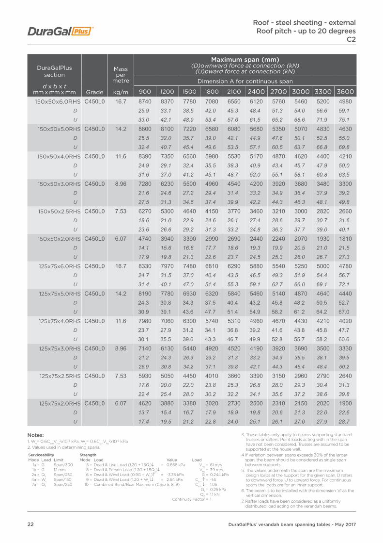
22 DuraGalPlus® verandah beam spanning tables - May 2017
DuraGalPlus section
d x b x tmm x mm x mm Grade
Mass per
metre
kg/m
Maximum span (mm)(D)ownward force at connection (kN)
(U)pward force at connection (kN)
Dimension A for continuous span
900 1200 1500 1800 2100 2400 2700 3000 3300 3600
150x50x6.0RHS C450L0 16.7 8740 8370 7780 7080 6550 6120 5760 5460 5200 4980D 25.9 33.1 38.5 42.0 45.3 48.4 51.3 54.0 56.6 59.1U 33.0 42.1 48.9 53.4 57.6 61.5 65.2 68.6 71.9 75.1
150x50x5.0RHS C450L0 14.2 8600 8100 7220 6580 6080 5680 5350 5070 4830 4630D 25.5 32.0 35.7 39.0 42.1 44.9 47.6 50.1 52.5 55.0U 32.4 40.7 45.4 49.6 53.5 57.1 60.5 63.7 66.8 69.8
150x50x4.0RHS C450L0 11.6 8390 7350 6560 5980 5530 5170 4870 4620 4400 4210D 24.9 29.1 32.4 35.5 38.3 40.9 43.4 45.7 47.9 50.0U 31.6 37.0 41.2 45.1 48.7 52.0 55.1 58.1 60.8 63.5
150x50x3.0RHS C450L0 8.96 7280 6230 5500 4960 4540 4200 3920 3680 3480 3300D 21.6 24.6 27.2 29.4 31.4 33.2 34.9 36.4 37.9 39.2U 27.5 31.3 34.6 37.4 39.9 42.2 44.3 46.3 48.1 49.8
150x50x2.5RHS C450L0 7.53 6270 5300 4640 4150 3770 3460 3210 3000 2820 2660D 18.6 21.0 22.9 24.6 26.1 27.4 28.6 29.7 30.7 31.6U 23.6 26.6 29.2 31.3 33.2 34.8 36.3 37.7 39.0 40.1
150x50x2.0RHS C450L0 6.07 4740 3940 3390 2990 2690 2440 2240 2070 1930 1810D 14.1 15.6 16.8 17.7 18.6 19.3 19.9 20.5 21.0 21.5U 17.9 19.8 21.3 22.6 23.7 24.5 25.3 26.0 26.7 27.3
125x75x6.0RHS C450L0 16.7 8330 7970 7480 6810 6290 5880 5540 5250 5000 4780D 24.7 31.5 37.0 40.4 43.5 46.5 49.3 51.9 54.4 56.7U 31.4 40.1 47.0 51.4 55.3 59.1 62.7 66.0 69.1 72.1
125x75x5.0RHS C450L0 14.2 8190 7780 6930 6320 5840 5460 5140 4870 4640 4440D 24.3 30.8 34.3 37.5 40.4 43.2 45.8 48.2 50.5 52.7U 30.9 39.1 43.6 47.7 51.4 54.9 58.2 61.2 64.2 67.0
125x75x4.0RHS C450L0 11.6 7980 7060 6300 5740 5310 4960 4670 4430 4210 4020D 23.7 27.9 31.2 34.1 36.8 39.2 41.6 43.8 45.8 47.7U 30.1 35.5 39.6 43.3 46.7 49.9 52.8 55.7 58.2 60.6
125x75x3.0RHS C450L0 8.96 7140 6130 5440 4920 4520 4190 3920 3690 3500 3330D 21.2 24.3 26.9 29.2 31.3 33.2 34.9 36.5 38.1 39.5
U 26.9 30.8 34.2 37.1 39.8 42.1 44.3 46.4 48.4 50.2
125x75x2.5RHS C450L0 7.53 5930 5050 4450 4010 3660 3390 3150 2960 2790 2640D 17.6 20.0 22.0 23.8 25.3 26.8 28.0 29.3 30.4 31.3U 22.4 25.4 28.0 30.2 32.2 34.1 35.6 37.2 38.6 39.8
125x75x2.0RHS C450L0 6.07 4620 3880 3380 3020 2730 2500 2310 2150 2020 1900D 13.7 15.4 16.7 17.9 18.9 19.8 20.6 21.3 22.0 22.6U 17.4 19.5 21.2 22.8 24.0 25.1 26.1 27.0 27.9 28.7
Roof - steel sheeting - externalRoof pitch - up to 20 degrees
C2
Notes:1. Wu= 0.6Cp,nVhu
2x10⁻³ kPa, Ws= 0.6Cp,nVhs2x10-3 kPa
2. Values used in determining spans.
Serviceability StrengthMode Load Limit Mode Load Value Load
1a = G Span/300 5 = Dead & Live Load (1.2G + 1.5Q1)↓ = 0.668 kPa Vhu = 61 m/s1b = G 12 mm 8 = Dead & Person Load (1.2G + 1.5Q2)↓ Vhs = 39 m/s2a = Q1 Span/250 6 = Dead & Wind Load (0.9G + Wu)↑ = -3.35 kPa G = 0.244 kPa4a = Ws Span/150 9 = Dead & Wind Load (1.2G + Wu)↓ = 2.64 kPa Cp,n ↑ = -1.67a = Q2 Span/250 10 = Combined Bend/Bear Maximum (Case 5, 8, 9) Cp,n ↓ = 1.05
Q1 = 0.25 kPaQ2 = 1.1 kN
Continuity Factor = 1
3. These tables only apply to beams supporting standard trusses or rafters. Point loads acting with in the span have not been considered. Trusses are assumed to be supported at the house wall.
4 If variation between spans exceeds 30% of the larger span, the beam should be considered as single span between supports.
5. The values underneath the span are the maximum design loads at the support for the given span. D refers to downward force, U to upward force. For continuous spans the loads are for an inner support.
6. The beam is to be installed with the dimension ‘d’ as the vertical dimension.
7. Rafter loads have been considered as a uniformly distributed load acting on the verandah beams.

23DuraGalPlus® verandah beam spanning tables - May 2017
DuraGalPlus section
d x b x tmm x mm x mm Grade
Mass per
metre
kg/m
Maximum span (mm)(D)ownward force at connection (kN)
(U)pward force at connection (kN)
Dimension A for continuous span
900 1200 1500 1800 2100 2400 2700 3000 3300 3600100x50x5.0RHS C450L0 10.3 6590 5720 5110 4660 4310 4020 3790 3600 3430 3280
D 19.6 22.6 25.3 27.7 29.8 31.8 33.7 35.6 37.3 38.9U 24.9 28.8 32.1 35.1 37.9 40.4 42.9 45.3 47.4 49.5
100x50x4.0RHS C450L0 8.49 6070 5240 4670 4260 3940 3690 3470 3290 3140 3000D 18.0 20.7 23.1 25.3 27.3 29.2 30.9 32.5 34.2 35.6U 22.9 26.3 29.4 32.1 34.7 37.1 39.3 41.4 43.4 45.3
100x50x3.5RHS C450L0 7.53 5730 4950 4420 4030 3730 3490 3290 3120 2970 2840D 17.0 19.6 21.9 23.9 25.8 27.6 29.3 30.9 32.3 33.7U 21.6 24.9 27.8 30.4 32.8 35.1 37.2 39.2 41.1 42.8
100x50x3.0RHS C450L0 6.6 5400 4670 4170 3800 3520 3290 3100 2940 2800 2680D 16.0 18.5 20.6 22.6 24.4 26.0 27.6 29.1 30.5 31.8U 20.4 23.5 26.2 28.7 31.0 33.1 35.1 37.0 38.7 40.4
100x50x2.5RHS C450L0 5.56 4970 4300 3840 3500 3210 2980 2790 2630 2490 2370D 14.7 17.0 19.0 20.8 22.2 23.6 24.8 26.0 27.1 28.1U 18.7 21.6 24.1 26.4 28.2 30.0 31.6 33.1 34.4 35.8
100x50x2.0RHS C450L0 4.50 4300 3660 3220 2890 2640 2440 2270 2120 2000 1900D 12.8 14.5 15.9 17.2 18.3 19.3 20.2 21.0 21.8 22.6U 16.2 18.4 20.2 21.8 23.2 24.5 25.7 26.6 27.7 28.7
100x50x1.6RHS C450L0 3.64 3280 2750 2390 2130 1930 1770 1630 1520 1420 1340D 9.73 10.9 11.8 12.6 13.4 14.0 14.5 15.0 15.4 15.9U 12.4 13.8 15.0 16.1 17.0 17.8 18.4 19.1 19.6 20.2
100x100x3.0SHS C450L0 8.96 5540 4690 4100 3670 3330 3060 2840 2650 2490 2350D 16.4 18.6 20.3 21.8 23.1 24.2 25.3 26.2 27.1 27.9U 20.9 23.6 25.8 27.7 29.3 30.8 32.1 33.3 34.4 35.4
100x100x2.5SHS C450L0 7.53 4960 4210 3700 3310 3020 2780 2580 2410 2270 2150D 14.7 16.7 18.3 19.6 20.9 22.0 23.0 23.8 24.7 25.5U 18.7 21.2 23.3 25.0 26.6 28.0 29.2 30.3 31.4 32.4
100x100x2.0SHS C450L0 6.07 4340 3690 3250 2920 2660 2460 2290 2140 2020 1910D 12.9 14.6 16.1 17.3 18.4 19.5 20.4 21.2 22.0 22.7U 16.4 18.6 20.4 22.0 23.4 24.7 25.9 26.9 27.9 28.8
90x90x2.0SHS C450L0 5.45 4050 3450 3040 2730 2500 2310 2150 2020 1900 1800D 12.0 13.6 15.0 16.2 17.3 18.3 19.1 20.0 20.7 21.4U 15.3 17.3 19.1 20.6 22.0 23.2 24.3 25.4 26.3 27.2
Roof - steel sheeting - externalRoof pitch - up to 20 degreesC2
Notes:1. Wu= 0.6Cp,nVhu
2x10⁻³ kPa, Ws= 0.6Cp,nVhs2x10-3 kPa
2. Values used in determining spans.
Serviceability StrengthMode Load Limit Mode Load Value Load
1a = G Span/300 5 = Dead & Live Load (1.2G + 1.5Q1)↓ = 0.668 kPa Vhu = 61 m/s1b = G 12 mm 8 = Dead & Person Load (1.2G + 1.5Q2)↓ Vhs = 39 m/s2a = Q1 Span/250 6 = Dead & Wind Load (0.9G + Wu)↑ = -3.35 kPa G = 0.244 kPa4a = Ws Span/150 9 = Dead & Wind Load (1.2G + Wu)↓ = 2.64 kPa Cp,n ↑ = -1.67a = Q2 Span/250 10 = Combined Bend/Bear Maximum (Case 5, 8, 9) Cp,n ↓ = 1.05
Q1 = 0.25 kPaQ2 = 1.1 kN
Continuity Factor = 1
3. These tables only apply to beams supporting standard trusses or rafters. Point loads acting with in the span have not been considered. Trusses are assumed to be supported at the house wall.
4 If variation between spans exceeds 30% of the larger span, the beam should be considered as single span between supports.
5. The values underneath the span are the maximum design loads at the support for the given span. D refers to downward force, U to upward force. For continuous spans the loads are for an inner support.
6. The beam is to be installed with the dimension ‘d’ as the vertical dimension.
7. Rafter loads have been considered as a uniformly distributed load acting on the verandah beams.

24 DuraGalPlus® verandah beam spanning tables - May 2017
DuraGalPlus section
d x b x tmm x mm x mm Grade
Mass per
metre
kg/m
Maximum span (mm)(D)ownward force at connection (kN)
(U)pward force at connection (kN)
Dimension A for single span
900 1200 1500 1800 2100 2400 2700 3000 3300 3600
150x50x6.0RHS C450L0 16.7 5560 5230 4980 4780 4620 4480 4350 4250 4150 4070D 8.57 10.7 12.8 14.7 16.6 18.4 20.1 21.8 23.4 25.1U 6.91 8.67 10.3 11.9 13.4 14.8 16.2 17.6 18.9 20.2
150x50x5.0RHS C450L0 14.2 5420 5090 4840 4640 4480 4340 4220 4120 4030 3950D 8.35 10.5 12.4 14.3 16.1 17.8 19.5 21.2 22.8 24.3U 6.74 8.44 10.0 11.5 13.0 14.4 15.7 17.1 18.4 19.6
150x50x4.0RHS C450L0 11.6 5220 4900 4660 4460 4310 4170 4060 3960 3870 3790D 8.04 10.1 12.0 13.7 15.5 17.1 18.8 20.3 21.9 23.4U 6.49 8.12 9.65 11.1 12.5 13.8 15.1 16.4 17.6 18.8
150x50x3.0RHS C450L0 8.96 4980 4660 4420 4240 4080 3960 3840 3750 3660 3580D 7.67 9.57 11.4 13.1 14.7 16.3 17.8 19.3 20.7 22.1U 6.19 7.72 9.16 10.5 11.8 13.1 14.3 15.5 16.7 17.8
150x50x2.5RHS C450L0 7.53 4800 4490 4260 4080 3930 3810 3700 3600 3500 3370D 7.40 9.22 10.9 12.6 14.1 15.7 17.1 18.5 19.8 20.8U 5.97 7.44 8.83 10.1 11.4 12.6 13.8 14.9 16.0 16.8
150x50x2.0RHS C450L0 6.07 4580 4280 4060 3880 3740 3520 3320 3150 3000 2880D 7.06 8.79 10.4 12.0 13.4 14.5 15.3 16.2 16.9 17.8U 5.69 7.09 8.41 9.65 10.8 11.7 12.4 13.1 13.7 14.3
125x75x6.0RHS C450L0 16.7 5300 4980 4740 4550 4400 4260 4150 4050 3960 3870D 8.17 10.2 12.2 14.0 15.8 17.5 19.2 20.8 22.4 23.9U 6.59 8.25 9.82 11.3 12.8 14.1 15.5 16.8 18.0 19.2
125x75x5.0RHS C450L0 14.2 5160 4840 4610 4420 4260 4130 4020 3920 3830 3750D 7.95 9.94 11.8 13.6 15.3 17.0 18.6 20.1 21.6 23.1U 6.41 8.02 9.55 11.0 12.4 13.7 15.0 16.2 17.5 18.6
125x75x4.0RHS C450L0 11.6 4970 4660 4430 4240 4090 3970 3860 3760 3680 3600D 7.66 9.57 11.4 13.1 14.7 16.3 17.8 19.3 20.8 22.2U 6.18 7.72 9.18 10.5 11.9 13.2 14.4 15.6 16.8 17.9
125x75x3.0RHS C450L0 8.96 4730 4420 4200 4020 3880 3760 3650 3550 3440 3340D 7.29 9.08 10.8 12.4 14.0 15.5 16.9 18.2 19.4 20.6
U 5.88 7.33 8.70 9.99 11.3 12.5 13.6 14.7 15.7 16.6
125x75x2.5RHS C450L0 7.53 4560 4260 4040 3870 3730 3610 3470 3300 3140 3010D 7.03 8.75 10.4 11.9 13.4 14.8 16.0 16.9 17.7 18.6U 5.67 7.06 8.37 9.62 10.8 12.0 12.9 13.7 14.3 15.0
125x75x2.0RHS C450L0 6.07 4350 4060 3850 3590 3330 3110 2940 2790 2660 2550D 6.70 8.34 9.89 11.1 12.0 12.8 13.6 14.3 15.0 15.7U 5.41 6.73 7.98 8.92 9.66 10.3 11.0 11.6 12.1 12.7
Roof - masonry tiles and ceiling - externalRoof pitch - up to 20 degrees
C2
Notes:1. Wu= 0.6Cp,nVhu
2x10⁻³ kPa, Ws= 0.6Cp,nVhs2x10-3 kPa
2. Values used in determining spans.
Serviceability StrengthMode Load Limit Mode Load Value Load
1a = G Span/300 5 = Dead & Live Load (1.2G + 1.5Q1)↓ = 1.46 kPa Vhu = 61 m/s1b = G 12 mm 8 = Dead & Person Load (1.2G + 1.5Q2)↓ Vhs = 39 m/s2a = Q1 Span/250 6 = Dead & Wind Load (0.9G + Wu)↑ = -2.76 kPa G = 0.9 kPa4a = Ws Span/150 9 = Dead & Wind Load (1.2G + Wu)↓ = 3.42 kPa Cp,n ↑ = -1.67a = Q2 Span/250 10 = Combined Bend/Bear Maximum (Case 5, 8, 9) Cp,n ↓ = 1.05
Q1 = 0.25 kPaQ2 = 1.1 kN
Continuity Factor = 1
3. These tables only apply to beams supporting standard trusses or rafters. Point loads acting with in the span have not been considered. Trusses are assumed to be supported at the house wall.
4 If variation between spans exceeds 30% of the larger span, the beam should be considered as single span between supports.
5. The values underneath the span are the maximum design loads at the support for the given span. D refers to downward force, U to upward force. For continuous spans the loads are for an inner support.
6. The beam is to be installed with the dimension ‘d’ as the vertical dimension.
7. Rafter loads have been considered as a uniformly distributed load acting on the verandah beams.

25DuraGalPlus® verandah beam spanning tables - May 2017
DuraGalPlus section
d x b x tmm x mm x mm Grade
Mass per
metre
kg/m
Maximum span (mm)(D)ownward force at connection (kN)
(U)pward force at connection (kN)
Dimension A for single span
900 1200 1500 1800 2100 2400 2700 3000 3300 3600
100x50x5.0RHS C450L0 10.3 4190 3930 3730 3570 3400 3260 3140 3030 2940 2860D 6.46 8.07 9.58 11.0 12.2 13.4 14.5 15.6 16.6 17.6U 5.21 6.51 7.73 8.87 9.86 10.8 11.7 12.6 13.4 14.2
100x50x4.0RHS C450L0 8.49 4050 3790 3600 3400 3240 3100 2990 2890 2800 2720D 6.24 7.79 9.25 10.5 11.6 12.7 13.8 14.8 15.8 16.8U 5.03 6.28 7.46 8.45 9.40 10.3 11.1 12.0 12.8 13.5
100x50x3.5RHS C450L0 7.53 3960 3710 3490 3290 3130 3000 2890 2790 2710 2630D 6.10 7.62 8.96 10.1 11.3 12.3 13.4 14.3 15.3 16.2U 4.92 6.15 7.23 8.18 9.08 9.94 10.8 11.6 12.4 13.1
100x50x3.0RHS C450L0 6.6 3870 3620 3380 3190 3030 2900 2800 2700 2620 2550D 5.96 7.44 8.68 9.83 10.9 11.9 12.9 13.9 14.8 15.7U 4.81 6.00 7.00 7.93 8.79 9.61 10.4 11.2 11.9 12.7
100x50x2.5RHS C450L0 5.56 3730 3450 3220 3030 2890 2760 2660 2570 2490 2420D 5.75 7.09 8.27 9.34 10.4 11.3 12.3 13.2 14.1 14.9U 4.64 5.72 6.67 7.53 8.38 9.15 9.92 10.6 11.3 12.0
100x50x2.0RHS C450L0 4.50 3560 3240 3020 2850 2710 2590 2490 2390 2280 2180D 5.49 6.66 7.76 8.78 9.74 10.6 11.5 12.3 12.9 13.4U 4.42 5.37 6.26 7.08 7.86 8.58 9.29 9.90 10.4 10.8
100x50x1.6RHS C450L0 3.64 3340 3040 2790 2550 2360 2210 2090 1980 1890 1810D 5.15 6.25 7.17 7.86 8.49 9.08 9.66 10.2 10.7 11.2U 4.15 5.04 5.78 6.34 6.84 7.33 7.79 8.20 8.61 9.00
100x100x3.0SHS C450L0 8.96 4370 4090 3880 3720 3580 3430 3300 3190 3090 2990D 6.73 8.40 9.96 11.5 12.9 14.1 15.3 16.4 17.5 18.4U 5.43 6.78 8.04 9.25 10.4 11.4 12.3 13.2 14.1 14.9
100x100x2.5SHS C450L0 7.53 4210 3940 3740 3570 3400 3190 3010 2860 2730 2610D 6.49 8.09 9.60 11.0 12.2 13.1 13.9 14.7 15.4 16.1U 5.23 6.53 7.75 8.87 9.86 10.6 11.2 11.8 12.4 13.0
100x100x2.0SHS C450L0 6.07 4020 3760 3420 3130 2900 2710 2560 2430 2320 2220D 6.19 7.73 8.78 9.65 10.4 11.1 11.8 12.5 13.1 13.7U 5.00 6.23 7.08 7.78 8.41 8.98 9.55 10.1 10.6 11.0
90x90x2.0SHS C450L0 5.45 3710 3420 3160 2890 2670 2500 2360 2240 2140 2050D 5.72 7.03 8.12 8.91 9.60 10.3 10.9 11.5 12.1 12.6U 4.61 5.67 6.55 7.18 7.74 8.29 8.80 9.28 9.75 10.2
Roof - masonry tiles and ceiling - externalRoof pitch - up to 20 degreesC2
Notes:1. Wu= 0.6Cp,nVhu
2x10⁻³ kPa, Ws= 0.6Cp,nVhs2x10-3 kPa
2. Values used in determining spans.
Serviceability StrengthMode Load Limit Mode Load Value Load
1a = G Span/300 5 = Dead & Live Load (1.2G + 1.5Q1)↓ = 1.46 kPa Vhu = 61 m/s1b = G 12 mm 8 = Dead & Person Load (1.2G + 1.5Q2)↓ Vhs = 39 m/s2a = Q1 Span/250 6 = Dead & Wind Load (0.9G + Wu)↑ = -2.76 kPa G = 0.9 kPa4a = Ws Span/150 9 = Dead & Wind Load (1.2G + Wu)↓ = 3.42 kPa Cp,n ↑ = -1.67a = Q2 Span/250 10 = Combined Bend/Bear Maximum (Case 5, 8, 9) Cp,n ↓ = 1.05
Q1 = 0.25 kPaQ2 = 1.1 kN
Continuity Factor = 1
3. These tables only apply to beams supporting standard trusses or rafters. Point loads acting with in the span have not been considered. Trusses are assumed to be supported at the house wall.
4 If variation between spans exceeds 30% of the larger span, the beam should be considered as single span between supports.
5. The values underneath the span are the maximum design loads at the support for the given span. D refers to downward force, U to upward force. For continuous spans the loads are for an inner support.
6. The beam is to be installed with the dimension ‘d’ as the vertical dimension.
7. Rafter loads have been considered as a uniformly distributed load acting on the verandah beams.

26 DuraGalPlus® verandah beam spanning tables - May 2017
DuraGalPlus section
d x b x tmm x mm x mm Grade
Mass per
metre
kg/m
Maximum span (mm)(D)ownward force at connection (kN)
(U)pward force at connection (kN)
Dimension A for continuous span
900 1200 1500 1800 2100 2400 2700 3000 3300 3600
150x50x6.0RHS C450L0 16.7 6930 6520 6210 5960 5750 5580 5420 5290 5070 4860D 26.7 33.5 39.9 45.9 51.7 57.3 62.6 67.9 71.6 74.9U 21.5 27.0 32.2 37.0 41.7 46.2 50.5 54.8 57.8 60.4
150x50x5.0RHS C450L0 14.2 6750 6340 6030 5790 5580 5410 5210 4950 4720 4520D 26.0 32.6 38.7 44.6 50.2 55.6 60.2 63.6 66.7 69.6U 21.0 26.3 31.2 36.0 40.5 44.8 48.6 51.3 53.8 56.2
150x50x4.0RHS C450L0 11.6 6510 6110 5800 5310 4890 4550 4270 4030 3820 3640D 25.1 31.4 37.2 40.9 44.0 46.7 49.3 51.7 54.0 56.1U 20.2 25.3 30.0 33.0 35.5 37.7 39.8 41.7 43.5 45.2
150x50x3.0RHS C450L0 8.96 6200 5390 4750 4270 3900 3600 3350 3150 2970 2810D 23.9 27.7 30.5 32.9 35.1 37.0 38.7 40.4 42.0 43.3U 19.3 22.3 24.6 26.5 28.3 29.8 31.2 32.6 33.8 34.9
150x50x2.5RHS C450L0 7.53 5390 4530 3950 3520 3190 2920 2710 2520 2360 2220D 20.8 23.3 25.4 27.1 28.7 30.0 31.3 32.4 33.3 34.2U 16.7 18.8 20.5 21.9 23.1 24.2 25.3 26.1 26.9 27.6
150x50x2.0RHS C450L0 6.07 4010 3300 2830 2490 2220 2010 1840 1700 1580 1480D 15.4 16.9 18.2 19.2 20.0 20.6 21.3 21.8 22.3 22.8U 12.5 13.7 14.7 15.5 16.1 16.7 17.2 17.6 18.0 18.4
125x75x6.0RHS C450L0 16.7 6600 6210 5910 5670 5480 5280 4960 4690 4460 4260D 25.4 31.9 37.9 43.7 49.3 54.2 57.3 60.2 63.0 65.6U 20.5 25.7 30.6 35.2 39.7 43.8 46.2 48.6 50.8 53.0
125x75x5.0RHS C450L0 14.2 6420 6030 5740 5510 5230 4870 4580 4320 4110 3920D 24.7 31.0 36.9 42.5 47.0 50.0 52.9 55.5 58.1 60.4U 19.9 25.0 29.7 34.2 37.9 40.4 42.7 44.7 46.8 48.7
125x75x4.0RHS C450L0 11.6 6190 5800 5520 5080 4670 4350 4070 3850 3650 3480D 23.8 29.8 35.4 39.1 42.0 44.7 47.0 49.4 51.6 53.6U 19.2 24.0 28.6 31.6 33.9 36.0 37.9 39.9 41.6 43.3
125x75x3.0RHS C450L0 8.96 5890 5330 4710 4260 3900 3620 3380 3180 3000 2850D 22.7 27.4 30.2 32.8 35.1 37.2 39.1 40.8 42.4 43.9
U 18.3 22.1 24.4 26.5 28.3 30.0 31.5 32.9 34.2 35.4
125x75x2.5RHS C450L0 7.53 5130 4360 3830 3440 3140 2890 2690 2520 2370 2240D 19.8 22.4 24.6 26.5 28.2 29.7 31.1 32.4 33.5 34.5U 15.9 18.1 19.8 21.4 22.8 23.9 25.1 26.1 27.0 27.8
125x75x2.0RHS C450L0 6.07 3950 3310 2870 2550 2300 2100 1940 1800 1680 1580D 15.2 17.0 18.4 19.6 20.7 21.6 22.4 23.1 23.7 24.3U 12.3 13.7 14.9 15.8 16.7 17.4 18.1 18.6 19.1 19.6
Roof - masonry tiles and ceiling - externalRoof pitch - up to 20 degrees
C2
Notes:1. Wu= 0.6Cp,nVhu
2x10⁻³ kPa, Ws= 0.6Cp,nVhs2x10-3 kPa
2. Values used in determining spans.
Serviceability StrengthMode Load Limit Mode Load Value Load
1a = G Span/300 5 = Dead & Live Load (1.2G + 1.5Q1)↓ = 1.46 kPa Vhu = 61 m/s1b = G 12 mm 8 = Dead & Person Load (1.2G + 1.5Q2)↓ Vhs = 39 m/s2a = Q1 Span/250 6 = Dead & Wind Load (0.9G + Wu)↑ = -2.76 kPa G = 0.9 kPa4a = Ws Span/150 9 = Dead & Wind Load (1.2G + Wu)↓ = 3.42 kPa Cp,n ↑ = -1.67a = Q2 Span/250 10 = Combined Bend/Bear Maximum (Case 5, 8, 9) Cp,n ↓ = 1.05
Q1 = 0.25 kPaQ2 = 1.1 kN
Continuity Factor = 1
3. These tables only apply to beams supporting standard trusses or rafters. Point loads acting with in the span have not been considered. Trusses are assumed to be supported at the house wall.
4 If variation between spans exceeds 30% of the larger span, the beam should be considered as single span between supports.
5. The values underneath the span are the maximum design loads at the support for the given span. D refers to downward force, U to upward force. For continuous spans the loads are for an inner support.
6. The beam is to be installed with the dimension ‘d’ as the vertical dimension.
7. Rafter loads have been considered as a uniformly distributed load acting on the verandah beams.

27DuraGalPlus® verandah beam spanning tables - May 2017
DuraGalPlus section
d x b x tmm x mm x mm Grade
Mass per
metre
kg/m
Maximum span (mm)(D)ownward force at connection (kN)
(U)pward force at connection (kN)
Dimension A for continuous span
900 1200 1500 1800 2100 2400 2700 3000 3300 3600100x50x5.0RHS C450L0 10.3 5220 4900 4650 4460 4200 3930 3710 3520 3360 3220
D 20.1 25.2 29.9 34.4 37.8 40.4 42.9 45.2 47.5 49.6U 16.2 20.3 24.1 27.7 30.5 32.6 34.6 36.5 38.3 40.0
100x50x4.0RHS C450L0 8.49 5050 4730 4490 4160 3850 3610 3400 3230 3080 2950D 19.5 24.3 28.8 32.1 34.6 37.1 39.3 41.5 43.5 45.5U 15.7 19.6 23.3 25.9 27.9 29.9 31.7 33.5 35.1 36.7
100x50x3.5RHS C450L0 7.53 4940 4620 4310 3940 3650 3420 3220 3060 2920 2800D 19.0 23.7 27.7 30.4 32.8 35.1 37.2 39.3 41.2 43.1U 15.4 19.1 22.3 24.5 26.5 28.3 30.0 31.7 33.3 34.8
100x50x3.0RHS C450L0 6.6 4820 4250 3780 3430 3160 2940 2760 2600 2470 2350D 18.6 21.8 24.3 26.4 28.4 30.2 31.9 33.4 34.9 36.2U 15.0 17.6 19.6 21.3 22.9 24.4 25.7 26.9 28.1 29.2
100x50x2.5RHS C450L0 5.56 4420 3780 3350 3030 2780 2570 2410 2270 2140 2040D 17.0 19.4 21.5 23.3 25.0 26.4 27.9 29.1 30.2 31.4U 13.7 15.7 17.3 18.8 20.2 21.3 22.5 23.5 24.4 25.4
100x50x2.0RHS C450L0 4.50 3710 3150 2760 2470 2250 2080 1930 1800 1700 1610D 14.3 16.2 17.7 19.0 20.2 21.4 22.3 23.1 24.0 24.8U 11.5 13.1 14.3 15.4 16.3 17.2 18.0 18.6 19.4 20.0
100x50x1.6RHS C450L0 3.64 2800 2340 2030 1800 1620 1480 1360 1270 1180 1110D 10.8 12.0 13.0 13.9 14.6 15.2 15.7 16.3 16.7 17.1U 8.70 9.70 10.5 11.2 11.7 12.3 12.7 13.2 13.4 13.8
100x100x3.0SHS C450L0 8.96 4760 4010 3490 3110 2820 2580 2390 2230 2090 1970D 18.3 20.6 22.4 24.0 25.3 26.5 27.6 28.6 29.5 30.4U 14.8 16.6 18.1 19.3 20.4 21.4 22.3 23.1 23.8 24.5
100x100x2.5SHS C450L0 7.53 4280 3610 3160 2820 2560 2360 2180 2040 1910 1810D 16.5 18.5 20.3 21.7 23.0 24.2 25.2 26.2 27.0 27.9U 13.3 15.0 16.4 17.5 18.6 19.6 20.3 21.1 21.8 22.5
100x100x2.0SHS C450L0 6.07 3750 3180 2790 2500 2270 2090 1950 1820 1710 1620D 14.4 16.3 17.9 19.3 20.4 21.5 22.5 23.4 24.2 25.0U 11.7 13.2 14.4 15.5 16.5 17.3 18.2 18.9 19.5 20.1
90x90x2.0SHS C450L0 5.45 3500 2970 2610 2340 2140 1970 1830 1720 1620 1530D 13.5 15.3 16.8 18.0 19.2 20.2 21.1 22.1 22.9 23.6U 10.9 12.3 13.5 14.5 15.5 16.3 17.1 17.8 18.5 19.0
Roof - masonry tiles and ceiling - externalRoof pitch - up to 20 degreesC2
Notes:1. Wu= 0.6Cp,nVhu
2x10⁻³ kPa, Ws= 0.6Cp,nVhs2x10-3 kPa
2. Values used in determining spans.
Serviceability StrengthMode Load Limit Mode Load Value Load
1a = G Span/300 5 = Dead & Live Load (1.2G + 1.5Q1)↓ = 1.46 kPa Vhu = 61 m/s1b = G 12 mm 8 = Dead & Person Load (1.2G + 1.5Q2)↓ Vhs = 39 m/s2a = Q1 Span/250 6 = Dead & Wind Load (0.9G + Wu)↑ = -2.76 kPa G = 0.9 kPa4a = Ws Span/150 9 = Dead & Wind Load (1.2G + Wu)↓ = 3.42 kPa Cp,n ↑ = -1.67a = Q2 Span/250 10 = Combined Bend/Bear Maximum (Case 5, 8, 9) Cp,n ↓ = 1.05
Q1 = 0.25 kPaQ2 = 1.1 kN
Continuity Factor = 1
3. These tables only apply to beams supporting standard trusses or rafters. Point loads acting with in the span have not been considered. Trusses are assumed to be supported at the house wall.
4 If variation between spans exceeds 30% of the larger span, the beam should be considered as single span between supports.
5. The values underneath the span are the maximum design loads at the support for the given span. D refers to downward force, U to upward force. For continuous spans the loads are for an inner support.
6. The beam is to be installed with the dimension ‘d’ as the vertical dimension.
7. Rafter loads have been considered as a uniformly distributed load acting on the verandah beams.

28 DuraGalPlus® verandah beam spanning tables - May 2017
DuraGalPlus section
d x b x tmm x mm x mm Grade
Mass per
metre
kg/m
Maximum span (mm)(D)ownward force at connection (kN)
(U)pward force at connection (kN)
Dimension A for single span
900 1200 1500 1800 2100 2400 2700 3000 3300 3600
150x50x6.0RHS C450L0 16.7 7020 6720 6470 6270 6090 5940 5760 5560 5390 5230D 8.33 10.6 12.8 14.9 16.9 18.8 20.5 22.0 23.5 24.8U 7.06 9.02 10.8 12.6 14.3 15.9 17.4 18.6 19.9 21.0
150x50x5.0RHS C450L0 14.2 6910 6590 6340 6130 5950 5740 5520 5330 5160 5010D 8.20 10.4 12.5 14.6 16.5 18.2 19.7 21.1 22.5 23.8U 6.95 8.84 10.6 12.3 14.0 15.4 16.7 17.9 19.0 20.2
150x50x4.0RHS C450L0 11.6 6740 6410 6150 5940 5660 5420 5210 5030 4870 4690D 8.00 10.1 12.2 14.1 15.7 17.2 18.6 19.9 21.2 22.3U 6.78 8.60 10.3 12.0 13.3 14.5 15.7 16.9 18.0 18.9
150x50x3.0RHS C450L0 8.96 6500 6160 5880 5530 5250 5030 4800 4560 4350 4170D 7.71 9.75 11.6 13.1 14.5 15.9 17.1 18.0 18.9 19.8U 6.54 8.26 9.86 11.1 12.3 13.5 14.5 15.3 16.0 16.8
150x50x2.5RHS C450L0 7.53 6320 5980 5570 5240 4980 4690 4420 4200 4000 3840D 7.50 9.46 11.0 12.4 13.8 14.8 15.7 16.6 17.4 18.2U 6.36 8.02 9.34 10.5 11.7 12.6 13.3 14.1 14.8 15.5
150x50x2.0RHS C450L0 6.07 6080 5610 5040 4610 4270 4000 3780 3580 3420 3270D 7.22 8.88 9.97 10.9 11.8 12.7 13.5 14.2 14.9 15.5U 6.12 7.53 8.45 9.28 10.0 10.7 11.4 12.0 12.6 13.2
125x75x6.0RHS C450L0 16.7 6680 6400 6170 5970 5800 5610 5400 5210 5050 4900D 7.93 10.1 12.2 14.2 16.1 17.8 19.2 20.6 22.0 23.3U 6.72 8.59 10.3 12.0 13.6 15.1 16.3 17.5 18.6 19.7
125x75x5.0RHS C450L0 14.2 6570 6270 6030 5830 5610 5370 5160 4980 4830 4690D 7.80 9.92 11.9 13.8 15.5 17.0 18.4 19.7 21.0 22.3U 6.61 8.41 10.1 11.7 13.2 14.4 15.6 16.7 17.8 18.9
125x75x4.0RHS C450L0 11.6 6410 6100 5850 5570 5290 5060 4870 4700 4550 4420D 7.61 9.65 11.6 13.2 14.7 16.0 17.3 18.6 19.8 21.0U 6.45 8.18 9.81 11.2 12.4 13.6 14.7 15.8 16.8 17.8
125x75x3.0RHS C450L0 8.96 6180 5850 5490 5160 4900 4690 4510 4340 4140 3960D 7.33 9.26 10.9 12.2 13.6 14.8 16.1 17.2 18.0 18.8
U 6.22 7.85 9.21 10.4 11.5 12.6 13.6 14.6 15.3 15.9
125x75x2.5RHS C450L0 7.53 6000 5600 5200 4820 4470 4190 3950 3750 3580 3430D 7.12 8.86 10.3 11.4 12.4 13.3 14.1 14.8 15.6 16.3U 6.04 7.51 8.72 9.70 10.5 11.2 11.9 12.6 13.2 13.8
125x75x2.0RHS C450L0 6.07 5730 4980 4470 4080 3790 3540 3340 3170 3030 2900D 6.80 7.88 8.84 9.68 10.5 11.2 11.9 12.5 13.2 13.8U 5.77 6.68 7.50 8.21 8.90 9.50 10.1 10.6 11.2 11.7
Roof - steel sheeting - externalRoof pitch - over 20 up to 35 degrees
C2
Notes:1. Wu= 0.6Cp,nVhu
2x10⁻³ kPa, Ws= 0.6Cp,nVhs2x10-3 kPa
2. Values used in determining spans.
Serviceability StrengthMode Load Limit Mode Load Value Load
1a = G Span/300 5 = Dead & Live Load (1.2G + 1.5Q1)↓ = 0.668 kPa Vhu = 61 m/s1b = G 12 mm 8 = Dead & Person Load (1.2G + 1.5Q2)↓ Vhs = 39 m/s2a = Q1 Span/250 6 = Dead & Wind Load (0.9G + Wu)↑ = -2.24 kPa G = 0.244 kPa4a = Ws Span/150 9 = Dead & Wind Load (1.2G + Wu)↓ = 2.64 kPa Cp,n ↑ = -1.17a = Q2 Span/250 10 = Combined Bend/Bear Maximum (Case 5, 8, 9) Cp,n ↓ = 1.05
Q1 = 0.25 kPaQ2 = 1.1 kN
Continuity Factor = 1
3. These tables only apply to beams supporting standard trusses or rafters. Point loads acting with in the span have not been considered. Trusses are assumed to be supported at the house wall.
4 If variation between spans exceeds 30% of the larger span, the beam should be considered as single span between supports.
5. The values underneath the span are the maximum design loads at the support for the given span. D refers to downward force, U to upward force. For continuous spans the loads are for an inner support.
6. The beam is to be installed with the dimension ‘d’ as the vertical dimension.
7. Rafter loads have been considered as a uniformly distributed load acting on the verandah beams.

29DuraGalPlus® verandah beam spanning tables - May 2017
DuraGalPlus section
d x b x tmm x mm x mm Grade
Mass per
metre
kg/m
Maximum span (mm)(D)ownward force at connection (kN)
(U)pward force at connection (kN)
Dimension A for single span
900 1200 1500 1800 2100 2400 2700 3000 3300 3600
100x50x5.0RHS C450L0 10.3 5440 5060 4700 4420 4200 4020 3860 3730 3610 3510D 6.46 8.01 9.30 10.5 11.6 12.7 13.7 14.8 15.7 16.7U 5.47 6.79 7.88 8.89 9.86 10.8 11.7 12.5 13.3 14.1
100x50x4.0RHS C450L0 8.49 5290 4810 4460 4200 3990 3820 3670 3540 3430 3330D 6.28 7.61 8.82 9.97 11.0 12.1 13.1 14.0 14.9 15.8U 5.32 6.45 7.48 8.45 9.37 10.2 11.1 11.9 12.7 13.4
100x50x3.5RHS C450L0 7.53 5120 4650 4310 4060 3860 3690 3550 3420 3320 3180D 6.08 7.36 8.53 9.64 10.7 11.7 12.6 13.5 14.4 15.1U 5.15 6.24 7.23 8.17 9.06 9.90 10.7 11.5 12.2 12.8
100x50x3.0RHS C450L0 6.6 4940 4490 4170 3920 3730 3560 3430 3290 3140 3000D 5.86 7.11 8.25 9.31 10.3 11.3 12.2 13.0 13.7 14.2U 4.97 6.02 6.99 7.89 8.76 9.55 10.4 11.0 11.6 12.1
100x50x2.5RHS C450L0 5.56 4690 4260 3960 3720 3540 3380 3200 3030 2890 2770D 5.57 6.74 7.83 8.83 9.80 10.7 11.4 12.0 12.6 13.2U 4.72 5.71 6.64 7.49 8.31 9.07 9.66 10.2 10.7 11.1
100x50x2.0RHS C450L0 4.50 4400 3990 3710 3490 3250 3040 2870 2720 2600 2490D 5.22 6.31 7.34 8.28 9.00 9.62 10.2 10.8 11.3 11.8U 4.43 5.35 6.22 7.02 7.63 8.16 8.66 9.12 9.59 10.0
100x50x1.6RHS C450L0 3.64 4090 3550 3180 2900 2690 2520 2370 2250 2150 2060D 4.85 5.62 6.29 6.88 7.45 7.98 8.44 8.90 9.36 9.78U 4.12 4.76 5.33 5.84 6.32 6.76 7.15 7.55 7.93 8.29
100x100x3.0SHS C450L0 8.96 5710 5320 4940 4650 4410 4160 3920 3730 3550 3400D 6.78 8.42 9.77 11.0 12.2 13.2 14.0 14.8 15.4 16.1U 5.75 7.14 8.28 9.36 10.4 11.2 11.8 12.5 13.1 13.7
100x100x2.5SHS C450L0 7.53 5540 5040 4570 4180 3880 3630 3430 3250 3100 2970D 6.58 7.98 9.04 9.92 10.7 11.5 12.2 12.9 13.5 14.1U 5.57 6.76 7.66 8.41 9.11 9.74 10.4 10.9 11.4 12.0
100x100x2.0SHS C450L0 6.07 5000 4340 3890 3560 3300 3090 2910 2760 2640 2530D 5.93 6.87 7.69 8.45 9.14 9.78 10.4 10.9 11.5 12.0U 5.03 5.82 6.52 7.16 7.75 8.29 8.78 9.26 9.74 10.2
90x90x2.0SHS C450L0 5.45 4610 4010 3590 3280 3040 2850 2690 2550 2430 2330D 5.47 6.35 7.10 7.79 8.42 9.02 9.58 10.1 10.6 11.1U 4.64 5.38 6.02 6.60 7.14 7.65 8.12 8.55 8.96 9.38
Roof - steel sheeting - externalRoof pitch - over 20 up to 35 degreesC2
Notes:1. Wu= 0.6Cp,nVhu
2x10⁻³ kPa, Ws= 0.6Cp,nVhs2x10-3 kPa
2. Values used in determining spans.
Serviceability StrengthMode Load Limit Mode Load Value Load
1a = G Span/300 5 = Dead & Live Load (1.2G + 1.5Q1)↓ = 0.668 kPa Vhu = 61 m/s1b = G 12 mm 8 = Dead & Person Load (1.2G + 1.5Q2)↓ Vhs = 39 m/s2a = Q1 Span/250 6 = Dead & Wind Load (0.9G + Wu)↑ = -2.24 kPa G = 0.244 kPa4a = Ws Span/150 9 = Dead & Wind Load (1.2G + Wu)↓ = 2.64 kPa Cp,n ↑ = -1.17a = Q2 Span/250 10 = Combined Bend/Bear Maximum (Case 5, 8, 9) Cp,n ↓ = 1.05
Q1 = 0.25 kPaQ2 = 1.1 kN
Continuity Factor = 1
3. These tables only apply to beams supporting standard trusses or rafters. Point loads acting with in the span have not been considered. Trusses are assumed to be supported at the house wall.
4 If variation between spans exceeds 30% of the larger span, the beam should be considered as single span between supports.
5. The values underneath the span are the maximum design loads at the support for the given span. D refers to downward force, U to upward force. For continuous spans the loads are for an inner support.
6. The beam is to be installed with the dimension ‘d’ as the vertical dimension.
7. Rafter loads have been considered as a uniformly distributed load acting on the verandah beams.

30 DuraGalPlus® verandah beam spanning tables - May 2017
DuraGalPlus section
d x b x tmm x mm x mm Grade
Mass per
metre
kg/m
Maximum span (mm)(D)ownward force at connection (kN)
(U)pward force at connection (kN)
Dimension A for continuous span
900 1200 1500 1800 2100 2400 2700 3000 3300 3600
150x50x6.0RHS C450L0 16.7 8740 8370 8070 7730 7180 6730 6350 6030 5760 5520D 25.9 33.1 39.9 45.9 49.7 53.3 56.5 59.6 62.7 65.5U 22.0 28.1 33.8 38.9 42.1 45.1 47.9 50.6 53.1 55.5
150x50x5.0RHS C450L0 14.2 8600 8210 7870 7210 6690 6270 5920 5620 5370 5140D 25.5 32.5 38.9 42.8 46.3 49.6 52.7 55.6 58.4 61.0U 21.6 27.5 33.0 36.3 39.3 42.1 44.7 47.1 49.5 51.7
150x50x4.0RHS C450L0 11.6 8390 7520 6710 6100 5620 5240 4920 4650 4410 4210D 24.9 29.8 33.2 36.2 38.9 41.5 43.8 46.0 48.0 50.0U 21.1 25.2 28.1 30.7 33.0 35.1 37.1 39.0 40.7 42.4
150x50x3.0RHS C450L0 8.96 7280 6230 5500 4960 4540 4200 3920 3680 3480 3300D 21.6 24.6 27.2 29.4 31.4 33.2 34.9 36.4 37.9 39.2U 18.3 20.9 23.1 25.0 26.6 28.2 29.6 30.9 32.1 33.2
150x50x2.5RHS C450L0 7.53 6270 5300 4640 4150 3770 3460 3210 3000 2820 2660D 18.6 21.0 22.9 24.6 26.1 27.4 28.6 29.7 30.7 31.6U 15.8 17.8 19.5 20.9 22.1 23.2 24.2 25.2 26.0 26.8
150x50x2.0RHS C450L0 6.07 4740 3940 3390 2990 2690 2440 2240 2070 1930 1810D 14.1 15.6 16.8 17.7 18.6 19.3 19.9 20.5 21.0 21.5U 11.9 13.2 14.2 15.0 15.8 16.4 16.9 17.4 17.8 18.2
125x75x6.0RHS C450L0 16.7 8330 7970 7680 7010 6480 6050 5690 5380 5120 4890D 24.7 31.5 38.0 41.6 44.9 47.9 50.7 53.2 55.7 58.0U 21.0 26.7 32.2 35.3 38.0 40.6 42.9 45.1 47.2 49.2
125x75x5.0RHS C450L0 14.2 8190 7820 7130 6490 6000 5590 5260 4970 4730 4510D 24.3 30.9 35.3 38.5 41.5 44.2 46.8 49.2 51.5 53.5U 20.6 26.2 29.9 32.6 35.2 37.5 39.7 41.7 43.6 45.4
125x75x4.0RHS C450L0 11.6 7980 7190 6410 5830 5370 5000 4700 4440 4210 4020D 23.7 28.4 31.7 34.6 37.2 39.6 41.8 43.9 45.8 47.7U 20.1 24.1 26.9 29.3 31.5 33.5 35.5 37.2 38.8 40.4
125x75x3.0RHS C450L0 8.96 7140 6130 5440 4920 4520 4190 3920 3690 3500 3330D 21.2 24.3 26.9 29.2 31.3 33.2 34.9 36.5 38.1 39.5
U 18.0 20.6 22.8 24.8 26.5 28.1 29.6 30.9 32.3 33.5
125x75x2.5RHS C450L0 7.53 5930 5050 4450 4010 3660 3390 3150 2960 2790 2640D 17.6 20.0 22.0 23.8 25.3 26.8 28.0 29.3 30.4 31.3U 14.9 16.9 18.7 20.2 21.5 22.7 23.8 24.8 25.7 26.6
125x75x2.0RHS C450L0 6.07 4620 3880 3380 3020 2730 2500 2310 2150 2020 1900D 13.7 15.4 16.7 17.9 18.9 19.8 20.6 21.3 22.0 22.6U 11.6 13.0 14.2 15.2 16.0 16.8 17.4 18.0 18.6 19.1
Roof - steel sheeting - externalRoof pitch - over 20 up to 35 degrees
C2
Notes:1. Wu= 0.6Cp,nVhu
2x10⁻³ kPa, Ws= 0.6Cp,nVhs2x10-3 kPa
2. Values used in determining spans.
Serviceability StrengthMode Load Limit Mode Load Value Load
1a = G Span/300 5 = Dead & Live Load (1.2G + 1.5Q1)↓ = 0.668 kPa Vhu = 61 m/s1b = G 12 mm 8 = Dead & Person Load (1.2G + 1.5Q2)↓ Vhs = 39 m/s2a = Q1 Span/250 6 = Dead & Wind Load (0.9G + Wu)↑ = -2.24 kPa G = 0.244 kPa4a = Ws Span/150 9 = Dead & Wind Load (1.2G + Wu)↓ = 2.64 kPa Cp,n ↑ = -1.17a = Q2 Span/250 10 = Combined Bend/Bear Maximum (Case 5, 8, 9) Cp,n ↓ = 1.05
Q1 = 0.25 kPaQ2 = 1.1 kN
Continuity Factor = 1
3. These tables only apply to beams supporting standard trusses or rafters. Point loads acting with in the span have not been considered. Trusses are assumed to be supported at the house wall.
4 If variation between spans exceeds 30% of the larger span, the beam should be considered as single span between supports.
5. The values underneath the span are the maximum design loads at the support for the given span. D refers to downward force, U to upward force. For continuous spans the loads are for an inner support.
6. The beam is to be installed with the dimension ‘d’ as the vertical dimension.
7. Rafter loads have been considered as a uniformly distributed load acting on the verandah beams.

31DuraGalPlus® verandah beam spanning tables - May 2017
DuraGalPlus section
d x b x tmm x mm x mm Grade
Mass per
metre
kg/m
Maximum span (mm)(D)ownward force at connection (kN)
(U)pward force at connection (kN)
Dimension A for continuous span
900 1200 1500 1800 2100 2400 2700 3000 3300 3600100x50x5.0RHS C450L0 10.3 6780 6260 5620 5140 4770 4470 4220 4000 3820 3660
D 20.1 24.8 27.8 30.5 33.0 35.4 37.6 39.6 41.6 43.4U 17.1 21.0 23.6 25.9 28.0 30.0 31.8 33.5 35.2 36.8
100x50x4.0RHS C450L0 8.49 6610 5760 5170 4730 4380 4100 3870 3680 3510 3360D 19.6 22.8 25.6 28.1 30.3 32.4 34.4 36.4 38.2 39.9U 16.6 19.3 21.7 23.8 25.7 27.5 29.2 30.9 32.4 33.8
100x50x3.5RHS C450L0 7.53 6280 5460 4900 4480 4150 3890 3670 3480 3320 3180D 18.6 21.6 24.2 26.6 28.7 30.8 32.7 34.4 36.1 37.7U 15.8 18.3 20.5 22.5 24.4 26.1 27.7 29.2 30.6 32.0
100x50x3.0RHS C450L0 6.6 5640 4870 4340 3940 3630 3380 3170 3000 2850 2720D 16.7 19.3 21.5 23.4 25.1 26.7 28.2 29.7 31.0 32.3U 14.2 16.3 18.2 19.8 21.3 22.7 23.9 25.2 26.3 27.4
100x50x2.5RHS C450L0 5.56 5070 4350 3860 3500 3210 2980 2790 2630 2490 2370D 15.0 17.2 19.1 20.8 22.2 23.6 24.8 26.0 27.1 28.1U 12.8 14.6 16.2 17.6 18.8 20.0 21.1 22.1 23.0 23.8
100x50x2.0RHS C450L0 4.50 4300 3660 3220 2890 2640 2440 2270 2120 2000 1900D 12.8 14.5 15.9 17.2 18.3 19.3 20.2 21.0 21.8 22.6U 10.8 12.3 13.5 14.5 15.5 16.4 17.1 17.8 18.4 19.1
100x50x1.6RHS C450L0 3.64 3280 2750 2390 2130 1930 1770 1630 1520 1420 1340D 9.73 10.9 11.8 12.6 13.4 14.0 14.5 15.0 15.4 15.9U 8.25 9.22 10.0 10.7 11.3 11.9 12.3 12.7 13.1 13.5
100x100x3.0SHS C450L0 8.96 5540 4690 4100 3670 3330 3060 2840 2650 2490 2350D 16.4 18.6 20.3 21.8 23.1 24.2 25.3 26.2 27.1 27.9U 13.9 15.7 17.2 18.5 19.5 20.5 21.4 22.2 23.0 23.6
100x100x2.5SHS C450L0 7.53 4960 4210 3700 3310 3020 2780 2580 2410 2270 2150D 14.7 16.7 18.3 19.6 20.9 22.0 23.0 23.8 24.7 25.5U 12.5 14.1 15.5 16.7 17.7 18.6 19.5 20.2 20.9 21.6
100x100x2.0SHS C450L0 6.07 4340 3690 3250 2920 2660 2460 2290 2140 2020 1910D 12.9 14.6 16.1 17.3 18.4 19.5 20.4 21.2 22.0 22.7U 10.9 12.4 13.6 14.7 15.6 16.5 17.3 17.9 18.6 19.2
90x90x2.0SHS C450L0 5.45 4050 3450 3040 2730 2500 2310 2150 2020 1900 1800D 12.0 13.6 15.0 16.2 17.3 18.3 19.1 20.0 20.7 21.4U 10.2 11.6 12.7 13.7 14.7 15.5 16.2 16.9 17.5 18.1
Roof - steel sheeting - externalRoof pitch - over 20 up to 35 degreesC2
Notes:1. Wu= 0.6Cp,nVhu
2x10⁻³ kPa, Ws= 0.6Cp,nVhs2x10-3 kPa
2. Values used in determining spans.
Serviceability StrengthMode Load Limit Mode Load Value Load
1a = G Span/300 5 = Dead & Live Load (1.2G + 1.5Q1)↓ = 0.668 kPa Vhu = 61 m/s1b = G 12 mm 8 = Dead & Person Load (1.2G + 1.5Q2)↓ Vhs = 39 m/s2a = Q1 Span/250 6 = Dead & Wind Load (0.9G + Wu)↑ = -2.24 kPa G = 0.244 kPa4a = Ws Span/150 9 = Dead & Wind Load (1.2G + Wu)↓ = 2.64 kPa Cp,n ↑ = -1.17a = Q2 Span/250 10 = Combined Bend/Bear Maximum (Case 5, 8, 9) Cp,n ↓ = 1.05
Q1 = 0.25 kPaQ2 = 1.1 kN
Continuity Factor = 1
3. These tables only apply to beams supporting standard trusses or rafters. Point loads acting with in the span have not been considered. Trusses are assumed to be supported at the house wall.
4 If variation between spans exceeds 30% of the larger span, the beam should be considered as single span between supports.
5. The values underneath the span are the maximum design loads at the support for the given span. D refers to downward force, U to upward force. For continuous spans the loads are for an inner support.
6. The beam is to be installed with the dimension ‘d’ as the vertical dimension.
7. Rafter loads have been considered as a uniformly distributed load acting on the verandah beams.

32 DuraGalPlus® verandah beam spanning tables - May 2017
DuraGalPlus section
d x b x tmm x mm x mm Grade
Mass per
metre
kg/m
Maximum span (mm)(D)ownward force at connection (kN)
(U)pward force at connection (kN)
Dimension A for single span
900 1200 1500 1800 2100 2400 2700 3000 3300 3600
150x50x6.0RHS C450L0 16.7 5560 5230 4980 4780 4620 4480 4350 4250 4150 4070D 8.57 10.7 12.8 14.7 16.6 18.4 20.1 21.8 23.4 25.1U 4.12 5.16 6.15 7.08 7.98 8.85 9.67 10.5 11.3 12.1
150x50x5.0RHS C450L0 14.2 5420 5090 4840 4640 4480 4340 4220 4120 4030 3950D 8.35 10.5 12.4 14.3 16.1 17.8 19.5 21.2 22.8 24.3U 4.01 5.03 5.97 6.87 7.74 8.57 9.38 10.2 10.9 11.7
150x50x4.0RHS C450L0 11.6 5220 4900 4660 4460 4310 4170 4060 3960 3870 3790D 8.04 10.1 12.0 13.7 15.5 17.1 18.8 20.3 21.9 23.4U 3.87 4.84 5.75 6.61 7.45 8.24 9.02 9.78 10.5 11.2
150x50x3.0RHS C450L0 8.96 4980 4660 4420 4240 4080 3960 3840 3750 3660 3580D 7.67 9.57 11.4 13.1 14.7 16.3 17.8 19.3 20.7 22.1U 3.69 4.60 5.46 6.28 7.05 7.82 8.53 9.26 9.94 10.6
150x50x2.5RHS C450L0 7.53 4800 4490 4260 4080 3930 3810 3700 3600 3500 3370D 7.40 9.22 10.9 12.6 14.1 15.7 17.1 18.5 19.8 20.8U 3.56 4.43 5.26 6.04 6.79 7.52 8.22 8.89 9.50 9.98
150x50x2.0RHS C450L0 6.07 4580 4280 4060 3880 3740 3520 3320 3150 3000 2880D 7.06 8.79 10.4 12.0 13.4 14.5 15.3 16.2 16.9 17.8U 3.39 4.23 5.01 5.75 6.46 6.95 7.38 7.78 8.15 8.53
125x75x6.0RHS C450L0 16.7 5300 4980 4740 4550 4400 4260 4150 4050 3960 3870D 8.17 10.2 12.2 14.0 15.8 17.5 19.2 20.8 22.4 23.9U 3.93 4.92 5.85 6.74 7.60 8.41 9.22 10.00 10.8 11.5
125x75x5.0RHS C450L0 14.2 5160 4840 4610 4420 4260 4130 4020 3920 3830 3750D 7.95 9.94 11.8 13.6 15.3 17.0 18.6 20.1 21.6 23.1U 3.82 4.78 5.69 6.55 7.36 8.16 8.93 9.68 10.4 11.1
125x75x4.0RHS C450L0 11.6 4970 4660 4430 4240 4090 3970 3860 3760 3680 3600D 7.66 9.57 11.4 13.1 14.7 16.3 17.8 19.3 20.8 22.2U 3.68 4.60 5.47 6.28 7.07 7.84 8.58 9.28 9.99 10.7
125x75x3.0RHS C450L0 8.96 4730 4420 4200 4020 3880 3760 3650 3550 3440 3340D 7.29 9.08 10.8 12.4 14.0 15.5 16.9 18.2 19.4 20.6
U 3.50 4.36 5.18 5.95 6.71 7.43 8.11 8.76 9.34 9.89
125x75x2.5RHS C450L0 7.53 4560 4260 4040 3870 3730 3610 3470 3300 3140 3010D 7.03 8.75 10.4 11.9 13.4 14.8 16.0 16.9 17.7 18.6U 3.38 4.21 4.99 5.73 6.45 7.13 7.71 8.15 8.53 8.92
125x75x2.0RHS C450L0 6.07 4350 4060 3850 3590 3330 3110 2940 2790 2660 2550D 6.70 8.34 9.89 11.1 12.0 12.8 13.6 14.3 15.0 15.7U 3.22 4.01 4.75 5.32 5.75 6.14 6.53 6.89 7.22 7.55
Roof - masonry tiles and ceiling - externalRoof pitch - over 20 up to 35 degrees
C2
Notes:1. Wu= 0.6Cp,nVhu
2x10⁻³ kPa, Ws= 0.6Cp,nVhs2x10-3 kPa
2. Values used in determining spans.
Serviceability StrengthMode Load Limit Mode Load Value Load
1a = G Span/300 5 = Dead & Live Load (1.2G + 1.5Q1)↓ = 1.46 kPa Vhu = 61 m/s1b = G 12 mm 8 = Dead & Person Load (1.2G + 1.5Q2)↓ Vhs = 39 m/s2a = Q1 Span/250 6 = Dead & Wind Load (0.9G + Wu)↑ = -1.65 kPa G = 0.9 kPa4a = Ws Span/150 9 = Dead & Wind Load (1.2G + Wu)↓ = 3.42 kPa Cp,n ↑ = -1.17a = Q2 Span/250 10 = Combined Bend/Bear Maximum (Case 5, 8, 9) Cp,n ↓ = 1.05
Q1 = 0.25 kPaQ2 = 1.1 kN
Continuity Factor = 1
3. These tables only apply to beams supporting standard trusses or rafters. Point loads acting with in the span have not been considered. Trusses are assumed to be supported at the house wall.
4 If variation between spans exceeds 30% of the larger span, the beam should be considered as single span between supports.
5. The values underneath the span are the maximum design loads at the support for the given span. D refers to downward force, U to upward force. For continuous spans the loads are for an inner support.
6. The beam is to be installed with the dimension ‘d’ as the vertical dimension.
7. Rafter loads have been considered as a uniformly distributed load acting on the verandah beams.
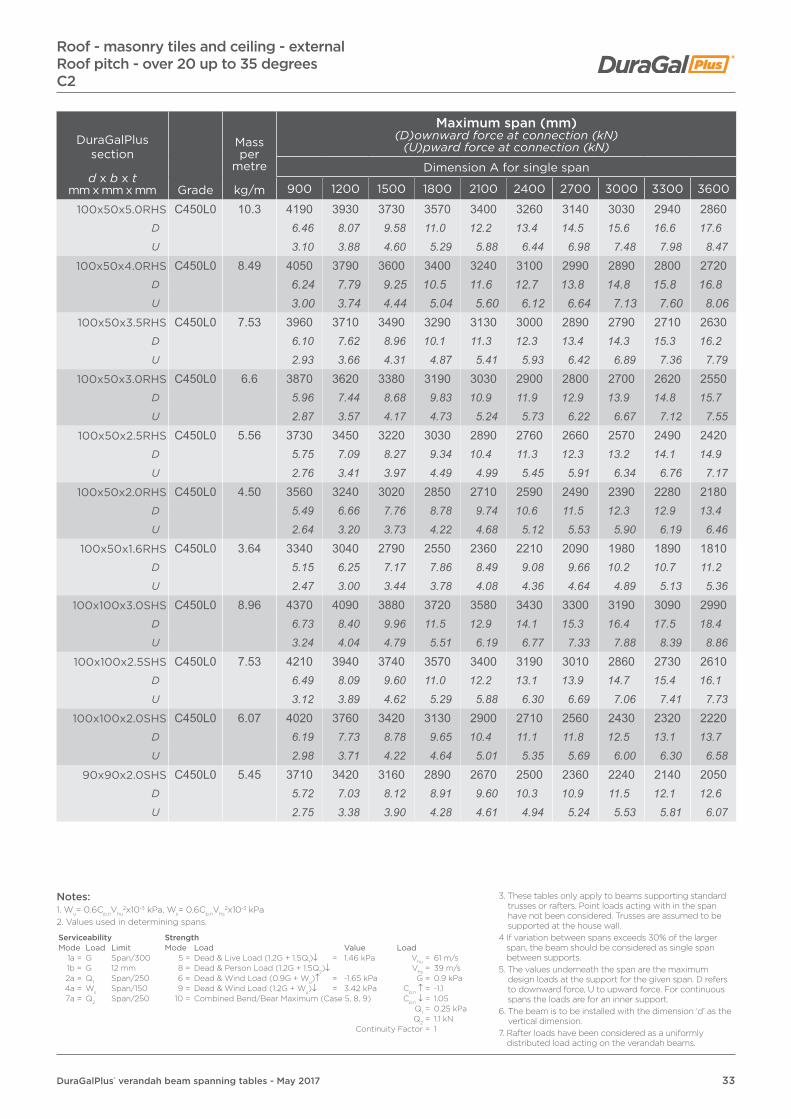
33DuraGalPlus® verandah beam spanning tables - May 2017
DuraGalPlus section
d x b x tmm x mm x mm Grade
Mass per
metre
kg/m
Maximum span (mm)(D)ownward force at connection (kN)
(U)pward force at connection (kN)
Dimension A for single span
900 1200 1500 1800 2100 2400 2700 3000 3300 3600
100x50x5.0RHS C450L0 10.3 4190 3930 3730 3570 3400 3260 3140 3030 2940 2860D 6.46 8.07 9.58 11.0 12.2 13.4 14.5 15.6 16.6 17.6U 3.10 3.88 4.60 5.29 5.88 6.44 6.98 7.48 7.98 8.47
100x50x4.0RHS C450L0 8.49 4050 3790 3600 3400 3240 3100 2990 2890 2800 2720D 6.24 7.79 9.25 10.5 11.6 12.7 13.8 14.8 15.8 16.8U 3.00 3.74 4.44 5.04 5.60 6.12 6.64 7.13 7.60 8.06
100x50x3.5RHS C450L0 7.53 3960 3710 3490 3290 3130 3000 2890 2790 2710 2630D 6.10 7.62 8.96 10.1 11.3 12.3 13.4 14.3 15.3 16.2U 2.93 3.66 4.31 4.87 5.41 5.93 6.42 6.89 7.36 7.79
100x50x3.0RHS C450L0 6.6 3870 3620 3380 3190 3030 2900 2800 2700 2620 2550D 5.96 7.44 8.68 9.83 10.9 11.9 12.9 13.9 14.8 15.7U 2.87 3.57 4.17 4.73 5.24 5.73 6.22 6.67 7.12 7.55
100x50x2.5RHS C450L0 5.56 3730 3450 3220 3030 2890 2760 2660 2570 2490 2420D 5.75 7.09 8.27 9.34 10.4 11.3 12.3 13.2 14.1 14.9U 2.76 3.41 3.97 4.49 4.99 5.45 5.91 6.34 6.76 7.17
100x50x2.0RHS C450L0 4.50 3560 3240 3020 2850 2710 2590 2490 2390 2280 2180D 5.49 6.66 7.76 8.78 9.74 10.6 11.5 12.3 12.9 13.4U 2.64 3.20 3.73 4.22 4.68 5.12 5.53 5.90 6.19 6.46
100x50x1.6RHS C450L0 3.64 3340 3040 2790 2550 2360 2210 2090 1980 1890 1810D 5.15 6.25 7.17 7.86 8.49 9.08 9.66 10.2 10.7 11.2U 2.47 3.00 3.44 3.78 4.08 4.36 4.64 4.89 5.13 5.36
100x100x3.0SHS C450L0 8.96 4370 4090 3880 3720 3580 3430 3300 3190 3090 2990D 6.73 8.40 9.96 11.5 12.9 14.1 15.3 16.4 17.5 18.4U 3.24 4.04 4.79 5.51 6.19 6.77 7.33 7.88 8.39 8.86
100x100x2.5SHS C450L0 7.53 4210 3940 3740 3570 3400 3190 3010 2860 2730 2610D 6.49 8.09 9.60 11.0 12.2 13.1 13.9 14.7 15.4 16.1U 3.12 3.89 4.62 5.29 5.88 6.30 6.69 7.06 7.41 7.73
100x100x2.0SHS C450L0 6.07 4020 3760 3420 3130 2900 2710 2560 2430 2320 2220D 6.19 7.73 8.78 9.65 10.4 11.1 11.8 12.5 13.1 13.7U 2.98 3.71 4.22 4.64 5.01 5.35 5.69 6.00 6.30 6.58
90x90x2.0SHS C450L0 5.45 3710 3420 3160 2890 2670 2500 2360 2240 2140 2050D 5.72 7.03 8.12 8.91 9.60 10.3 10.9 11.5 12.1 12.6U 2.75 3.38 3.90 4.28 4.61 4.94 5.24 5.53 5.81 6.07
Roof - masonry tiles and ceiling - externalRoof pitch - over 20 up to 35 degreesC2
Notes:1. Wu= 0.6Cp,nVhu
2x10⁻³ kPa, Ws= 0.6Cp,nVhs2x10-3 kPa
2. Values used in determining spans.
Serviceability StrengthMode Load Limit Mode Load Value Load
1a = G Span/300 5 = Dead & Live Load (1.2G + 1.5Q1)↓ = 1.46 kPa Vhu = 61 m/s1b = G 12 mm 8 = Dead & Person Load (1.2G + 1.5Q2)↓ Vhs = 39 m/s2a = Q1 Span/250 6 = Dead & Wind Load (0.9G + Wu)↑ = -1.65 kPa G = 0.9 kPa4a = Ws Span/150 9 = Dead & Wind Load (1.2G + Wu)↓ = 3.42 kPa Cp,n ↑ = -1.17a = Q2 Span/250 10 = Combined Bend/Bear Maximum (Case 5, 8, 9) Cp,n ↓ = 1.05
Q1 = 0.25 kPaQ2 = 1.1 kN
Continuity Factor = 1
3. These tables only apply to beams supporting standard trusses or rafters. Point loads acting with in the span have not been considered. Trusses are assumed to be supported at the house wall.
4 If variation between spans exceeds 30% of the larger span, the beam should be considered as single span between supports.
5. The values underneath the span are the maximum design loads at the support for the given span. D refers to downward force, U to upward force. For continuous spans the loads are for an inner support.
6. The beam is to be installed with the dimension ‘d’ as the vertical dimension.
7. Rafter loads have been considered as a uniformly distributed load acting on the verandah beams.

34 DuraGalPlus® verandah beam spanning tables - May 2017
Roof - masonry tiles and ceiling - externalRoof pitch - over 20 up to 35 degrees
C2
DuraGalPlus section
d x b x tmm x mm x mm Grade
Mass per
metre
kg/m
Maximum span (mm)(D)ownward force at connection (kN)
(U)pward force at connection (kN)
Dimension A for continuous span
900 1200 1500 1800 2100 2400 2700 3000 3300 3600
150x50x6.0RHS C450L0 16.7 6930 6520 6210 5960 5750 5580 5420 5290 5070 4860D 26.7 33.5 39.9 45.9 51.7 57.3 62.6 67.9 71.6 74.9U 12.8 16.1 19.2 22.1 24.8 27.6 30.1 32.6 34.4 36.0
150x50x5.0RHS C450L0 14.2 6750 6340 6030 5790 5580 5410 5210 4950 4720 4520D 26.0 32.6 38.7 44.6 50.2 55.6 60.2 63.6 66.7 69.6U 12.5 15.7 18.6 21.4 24.1 26.7 28.9 30.6 32.0 33.5
150x50x4.0RHS C450L0 11.6 6510 6110 5800 5310 4890 4550 4270 4030 3820 3640D 25.1 31.4 37.2 40.9 44.0 46.7 49.3 51.7 54.0 56.1U 12.1 15.1 17.9 19.7 21.1 22.5 23.7 24.9 25.9 27.0
150x50x3.0RHS C450L0 8.96 6200 5390 4750 4270 3900 3600 3350 3150 2970 2810D 23.9 27.7 30.5 32.9 35.1 37.0 38.7 40.4 42.0 43.3U 11.5 13.3 14.7 15.8 16.8 17.8 18.6 19.4 20.2 20.8
150x50x2.5RHS C450L0 7.53 5390 4530 3950 3520 3190 2920 2710 2520 2360 2220D 20.8 23.3 25.4 27.1 28.7 30.0 31.3 32.4 33.3 34.2U 9.98 11.2 12.2 13.0 13.8 14.4 15.1 15.6 16.0 16.4
150x50x2.0RHS C450L0 6.07 4010 3300 2830 2490 2220 2010 1840 1700 1580 1480D 15.4 16.9 18.2 19.2 20.0 20.6 21.3 21.8 22.3 22.8U 7.42 8.15 8.73 9.22 9.59 9.92 10.2 10.5 10.7 11.0
125x75x6.0RHS C450L0 16.7 6600 6210 5910 5670 5480 5280 4960 4690 4460 4260D 25.4 31.9 37.9 43.7 49.3 54.2 57.3 60.2 63.0 65.6U 12.2 15.3 18.2 21.0 23.7 26.1 27.6 28.9 30.3 31.6
125x75x5.0RHS C450L0 14.2 6420 6030 5740 5510 5230 4870 4580 4320 4110 3920D 24.7 31.0 36.9 42.5 47.0 50.0 52.9 55.5 58.1 60.4U 11.9 14.9 17.7 20.4 22.6 24.0 25.4 26.7 27.9 29.0
125x75x4.0RHS C450L0 11.6 6190 5800 5520 5080 4670 4350 4070 3850 3650 3480D 23.8 29.8 35.4 39.1 42.0 44.7 47.0 49.4 51.6 53.6U 11.5 14.3 17.0 18.8 20.2 21.5 22.6 23.8 24.8 25.8
125x75x3.0RHS C450L0 8.96 5890 5330 4710 4260 3900 3620 3380 3180 3000 2850D 22.7 27.4 30.2 32.8 35.1 37.2 39.1 40.8 42.4 43.9
U 10.9 13.2 14.5 15.8 16.8 17.9 18.8 19.6 20.4 21.1
125x75x2.5RHS C450L0 7.53 5130 4360 3830 3440 3140 2890 2690 2520 2370 2240D 19.8 22.4 24.6 26.5 28.2 29.7 31.1 32.4 33.5 34.5U 9.50 10.8 11.8 12.7 13.6 14.3 14.9 15.6 16.1 16.6
125x75x2.0RHS C450L0 6.07 3950 3310 2870 2550 2300 2100 1940 1800 1680 1580D 15.2 17.0 18.4 19.6 20.7 21.6 22.4 23.1 23.7 24.3U 7.31 8.17 8.86 9.44 9.94 10.4 10.8 11.1 11.4 11.7
Notes:1. Wu= 0.6Cp,nVhu
2x10⁻³ kPa, Ws= 0.6Cp,nVhs2x10-3 kPa
2. Values used in determining spans.
Serviceability StrengthMode Load Limit Mode Load Value Load
1a = G Span/300 5 = Dead & Live Load (1.2G + 1.5Q1)↓ = 1.46 kPa Vhu = 61 m/s1b = G 12 mm 8 = Dead & Person Load (1.2G + 1.5Q2)↓ Vhs = 39 m/s2a = Q1 Span/250 6 = Dead & Wind Load (0.9G + Wu)↑ = -1.65 kPa G = 0.9 kPa4a = Ws Span/150 9 = Dead & Wind Load (1.2G + Wu)↓ = 3.42 kPa Cp,n ↑ = -1.17a = Q2 Span/250 10 = Combined Bend/Bear Maximum (Case 5, 8, 9) Cp,n ↓ = 1.05
Q1 = 0.25 kPaQ2 = 1.1 kN
Continuity Factor = 1
3. These tables only apply to beams supporting standard trusses or rafters. Point loads acting with in the span have not been considered. Trusses are assumed to be supported at the house wall.
4 If variation between spans exceeds 30% of the larger span, the beam should be considered as single span between supports.
5. The values underneath the span are the maximum design loads at the support for the given span. D refers to downward force, U to upward force. For continuous spans the loads are for an inner support.
6. The beam is to be installed with the dimension ‘d’ as the vertical dimension.
7. Rafter loads have been considered as a uniformly distributed load acting on the verandah beams.
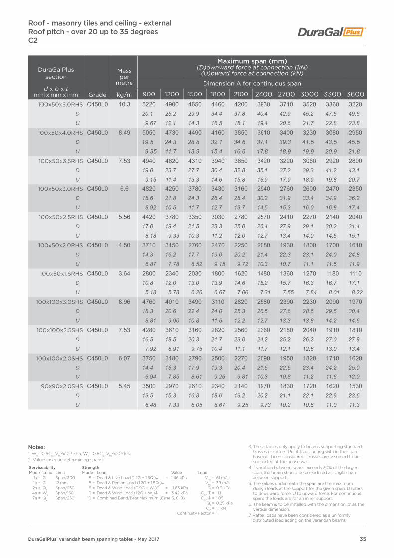
35DuraGalPlus® verandah beam spanning tables - May 2017
Roof - masonry tiles and ceiling - externalRoof pitch - over 20 up to 35 degreesC2
DuraGalPlus section
d x b x tmm x mm x mm Grade
Mass per
metre
kg/m
Maximum span (mm)(D)ownward force at connection (kN)
(U)pward force at connection (kN)
Dimension A for continuous span
900 1200 1500 1800 2100 2400 2700 3000 3300 3600100x50x5.0RHS C450L0 10.3 5220 4900 4650 4460 4200 3930 3710 3520 3360 3220
D 20.1 25.2 29.9 34.4 37.8 40.4 42.9 45.2 47.5 49.6U 9.67 12.1 14.3 16.5 18.1 19.4 20.6 21.7 22.8 23.8
100x50x4.0RHS C450L0 8.49 5050 4730 4490 4160 3850 3610 3400 3230 3080 2950D 19.5 24.3 28.8 32.1 34.6 37.1 39.3 41.5 43.5 45.5U 9.35 11.7 13.9 15.4 16.6 17.8 18.9 19.9 20.9 21.8
100x50x3.5RHS C450L0 7.53 4940 4620 4310 3940 3650 3420 3220 3060 2920 2800D 19.0 23.7 27.7 30.4 32.8 35.1 37.2 39.3 41.2 43.1U 9.15 11.4 13.3 14.6 15.8 16.9 17.9 18.9 19.8 20.7
100x50x3.0RHS C450L0 6.6 4820 4250 3780 3430 3160 2940 2760 2600 2470 2350D 18.6 21.8 24.3 26.4 28.4 30.2 31.9 33.4 34.9 36.2U 8.92 10.5 11.7 12.7 13.7 14.5 15.3 16.0 16.8 17.4
100x50x2.5RHS C450L0 5.56 4420 3780 3350 3030 2780 2570 2410 2270 2140 2040D 17.0 19.4 21.5 23.3 25.0 26.4 27.9 29.1 30.2 31.4U 8.18 9.33 10.3 11.2 12.0 12.7 13.4 14.0 14.5 15.1
100x50x2.0RHS C450L0 4.50 3710 3150 2760 2470 2250 2080 1930 1800 1700 1610D 14.3 16.2 17.7 19.0 20.2 21.4 22.3 23.1 24.0 24.8U 6.87 7.78 8.52 9.15 9.72 10.3 10.7 11.1 11.5 11.9
100x50x1.6RHS C450L0 3.64 2800 2340 2030 1800 1620 1480 1360 1270 1180 1110D 10.8 12.0 13.0 13.9 14.6 15.2 15.7 16.3 16.7 17.1U 5.18 5.78 6.26 6.67 7.00 7.31 7.55 7.84 8.01 8.22
100x100x3.0SHS C450L0 8.96 4760 4010 3490 3110 2820 2580 2390 2230 2090 1970D 18.3 20.6 22.4 24.0 25.3 26.5 27.6 28.6 29.5 30.4U 8.81 9.90 10.8 11.5 12.2 12.7 13.3 13.8 14.2 14.6
100x100x2.5SHS C450L0 7.53 4280 3610 3160 2820 2560 2360 2180 2040 1910 1810D 16.5 18.5 20.3 21.7 23.0 24.2 25.2 26.2 27.0 27.9U 7.92 8.91 9.75 10.4 11.1 11.7 12.1 12.6 13.0 13.4
100x100x2.0SHS C450L0 6.07 3750 3180 2790 2500 2270 2090 1950 1820 1710 1620D 14.4 16.3 17.9 19.3 20.4 21.5 22.5 23.4 24.2 25.0U 6.94 7.85 8.61 9.26 9.81 10.3 10.8 11.2 11.6 12.0
90x90x2.0SHS C450L0 5.45 3500 2970 2610 2340 2140 1970 1830 1720 1620 1530D 13.5 15.3 16.8 18.0 19.2 20.2 21.1 22.1 22.9 23.6U 6.48 7.33 8.05 8.67 9.25 9.73 10.2 10.6 11.0 11.3
Notes:1. Wu= 0.6Cp,nVhu
2x10⁻³ kPa, Ws= 0.6Cp,nVhs2x10-3 kPa
2. Values used in determining spans.
Serviceability StrengthMode Load Limit Mode Load Value Load
1a = G Span/300 5 = Dead & Live Load (1.2G + 1.5Q1)↓ = 1.46 kPa Vhu = 61 m/s1b = G 12 mm 8 = Dead & Person Load (1.2G + 1.5Q2)↓ Vhs = 39 m/s2a = Q1 Span/250 6 = Dead & Wind Load (0.9G + Wu)↑ = -1.65 kPa G = 0.9 kPa4a = Ws Span/150 9 = Dead & Wind Load (1.2G + Wu)↓ = 3.42 kPa Cp,n ↑ = -1.17a = Q2 Span/250 10 = Combined Bend/Bear Maximum (Case 5, 8, 9) Cp,n ↓ = 1.05
Q1 = 0.25 kPaQ2 = 1.1 kN
Continuity Factor = 1
3. These tables only apply to beams supporting standard trusses or rafters. Point loads acting with in the span have not been considered. Trusses are assumed to be supported at the house wall.
4 If variation between spans exceeds 30% of the larger span, the beam should be considered as single span between supports.
5. The values underneath the span are the maximum design loads at the support for the given span. D refers to downward force, U to upward force. For continuous spans the loads are for an inner support.
6. The beam is to be installed with the dimension ‘d’ as the vertical dimension.
7. Rafter loads have been considered as a uniformly distributed load acting on the verandah beams.

36 DuraGalPlus® verandah beam spanning tables - May 2017
DuraGalPlus section
d x b x tmm x mm x mm Grade
Mass per
metre
kg/m
Maximum span (mm)(D)ownward force at connection (kN)
(U)pward force at connection (kN)
Dimension A for single span
900 1200 1500 1800 2100 2400 2700 3000 3300 3600
150x50x6.0RHS C450L0 16.7 6470 5880 5460 5140 4880 4670 4490 4330 4200 4050D 10.9 13.2 15.3 17.3 19.2 21.0 22.7 24.3 25.9 27.3U 14.7 17.8 20.6 23.3 25.8 28.2 30.5 32.7 34.9 36.7
150x50x5.0RHS C450L0 14.2 6200 5630 5230 4920 4670 4470 4300 4130 3940 3770D 10.4 12.6 14.7 16.6 18.4 20.1 21.7 23.2 24.3 25.4U 14.1 17.0 19.8 22.3 24.7 27.0 29.2 31.2 32.7 34.2
150x50x4.0RHS C450L0 11.6 5850 5320 4940 4650 4410 4210 3960 3760 3580 3430D 9.85 11.9 13.9 15.7 17.3 18.9 20.0 21.1 22.1 23.1U 13.3 16.1 18.7 21.1 23.3 25.4 26.9 28.4 29.8 31.1
150x50x3.0RHS C450L0 8.96 5430 4930 4580 4310 3980 3720 3510 3330 3170 3040D 9.15 11.1 12.9 14.5 15.6 16.7 17.7 18.7 19.6 20.5U 12.3 14.9 17.3 19.5 21.0 22.5 23.9 25.2 26.3 27.6
150x50x2.5RHS C450L0 7.53 5150 4680 4340 3960 3660 3420 3230 3060 2920 2790D 8.67 10.5 12.2 13.3 14.4 15.4 16.3 17.2 18.0 18.8U 11.7 14.1 16.4 18.0 19.4 20.7 22.0 23.1 24.3 25.3
150x50x2.0RHS C450L0 6.07 4780 4140 3700 3370 3120 2920 2750 2610 2490 2380D 8.05 9.30 10.4 11.4 12.3 13.1 13.9 14.7 15.4 16.0U 10.8 12.5 14.0 15.3 16.5 17.6 18.7 19.7 20.7 21.6
125x75x6.0RHS C450L0 16.7 6070 5510 5120 4810 4570 4370 4210 4060 3930 3820D 10.2 12.4 14.4 16.2 18.0 19.6 21.3 22.8 24.3 25.7U 13.8 16.7 19.3 21.8 24.2 26.4 28.6 30.7 32.7 34.6
125x75x5.0RHS C450L0 14.2 5800 5270 4890 4610 4370 4180 4020 3880 3760 3620D 9.77 11.8 13.7 15.5 17.2 18.8 20.3 21.8 23.2 24.4U 13.1 15.9 18.5 20.9 23.1 25.3 27.3 29.3 31.2 32.8
125x75x4.0RHS C450L0 11.6 5470 4970 4620 4340 4130 3950 3790 3610 3440 3290D 9.21 11.2 13.0 14.6 16.2 17.7 19.2 20.3 21.2 22.2U 12.4 15.0 17.5 19.7 21.8 23.9 25.8 27.3 28.6 29.8
125x75x3.0RHS C450L0 8.96 5070 4610 4280 4020 3790 3540 3340 3170 3020 2890D 8.54 10.4 12.0 13.5 14.9 15.9 16.9 17.8 18.7 19.5
U 11.5 13.9 16.2 18.2 20.0 21.4 22.7 24.0 25.1 26.2
125x75x2.5RHS C450L0 7.53 4800 4340 3880 3540 3270 3060 2880 2730 2610 2500D 8.09 9.75 10.9 11.9 12.9 13.7 14.6 15.3 16.1 16.8U 10.9 13.1 14.7 16.0 17.3 18.5 19.6 20.6 21.7 22.7
125x75x2.0RHS C450L0 6.07 4240 3660 3270 2990 2760 2580 2440 2310 2200 2110D 7.14 8.22 9.18 10.1 10.8 11.6 12.3 13.0 13.6 14.2U 9.61 11.1 12.4 13.6 14.6 15.6 16.6 17.5 18.3 19.1
Roof - steel sheeting - externalRoof pitch - up to 20 degrees
C3
Notes:1. Wu= 0.6Cp,nVhu
2x10⁻³ kPa, Ws= 0.6Cp,nVhs2x10-3 kPa
2. Values used in determining spans.
Serviceability StrengthMode Load Limit Mode Load Value Load
1a = G Span/300 5 = Dead & Live Load (1.2G + 1.5Q1)↓ = 0.668 kPa Vhu = 74 m/s1b = G 12 mm 8 = Dead & Person Load (1.2G + 1.5Q2)↓ Vhs = 47 m/s2a = Q1 Span/250 6 = Dead & Wind Load (0.9G + Wu)↑ = -5.04 kPa G = 0.244 kPa4a = Ws Span/150 9 = Dead & Wind Load (1.2G + Wu)↓ = 3.74 kPa Cp,n ↑ = -1.67a = Q2 Span/250 10 = Combined Bend/Bear Maximum (Case 5, 8, 9) Cp,n ↓ = 1.05
Q1 = 0.25 kPaQ2 = 1.1 kN
Continuity Factor = 1
3. These tables only apply to beams supporting standard trusses or rafters. Point loads acting with in the span have not been considered. Trusses are assumed to be supported at the house wall.
4 If variation between spans exceeds 30% of the larger span, the beam should be considered as single span between supports.
5. The values underneath the span are the maximum design loads at the support for the given span. D refers to downward force, U to upward force. For continuous spans the loads are for an inner support.
6. The beam is to be installed with the dimension ‘d’ as the vertical dimension.
7. Rafter loads have been considered as a uniformly distributed load acting on the verandah beams.

37DuraGalPlus® verandah beam spanning tables - May 2017
DuraGalPlus section
d x b x tmm x mm x mm Grade
Mass per
metre
kg/m
Maximum span (mm)(D)ownward force at connection (kN)
(U)pward force at connection (kN)
Dimension A for single span
900 1200 1500 1800 2100 2400 2700 3000 3300 3600
100x50x5.0RHS C450L0 10.3 4340 3950 3660 3450 3280 3130 3010 2910 2790 2670D 7.31 8.87 10.3 11.6 12.9 14.1 15.2 16.3 17.2 18.0U 9.84 11.9 13.8 15.6 17.3 18.9 20.5 22.0 23.2 24.2
100x50x4.0RHS C450L0 8.49 4120 3750 3480 3270 3110 2970 2830 2680 2560 2450D 6.94 8.42 9.77 11.0 12.2 13.3 14.3 15.0 15.8 16.5U 9.34 11.3 13.1 14.8 16.4 18.0 19.2 20.2 21.3 22.2
100x50x3.5RHS C450L0 7.53 3990 3620 3360 3160 3010 2840 2680 2540 2420 2320D 6.72 8.13 9.43 10.6 11.8 12.8 13.5 14.3 14.9 15.6U 9.04 10.9 12.7 14.3 15.9 17.2 18.2 19.2 20.1 21.0
100x50x3.0RHS C450L0 6.6 3850 3500 3250 3060 2870 2680 2530 2400 2280 2190D 6.49 7.86 9.12 10.3 11.3 12.0 12.8 13.5 14.1 14.8U 8.73 10.6 12.3 13.9 15.2 16.2 17.2 18.1 18.9 19.9
100x50x2.5RHS C450L0 5.56 3660 3320 3080 2850 2640 2470 2330 2210 2110 2020D 6.16 7.46 8.65 9.60 10.4 11.1 11.8 12.4 13.0 13.6U 8.30 10.0 11.6 12.9 14.0 14.9 15.8 16.7 17.5 18.3
100x50x2.0RHS C450L0 4.50 3430 3110 2800 2560 2370 2210 2090 1980 1890 1810D 5.78 6.98 7.86 8.62 9.31 9.93 10.6 11.1 11.7 12.2U 7.77 9.40 10.6 11.6 12.5 13.4 14.2 15.0 15.7 16.4
100x50x1.6RHS C450L0 3.64 3000 2590 2320 2110 1960 1830 1730 1640 1560 1490D 5.05 5.82 6.51 7.11 7.70 8.22 8.74 9.21 9.63 10.0U 6.80 7.83 8.76 9.57 10.4 11.1 11.8 12.4 13.0 13.5
100x100x3.0SHS C450L0 8.96 4560 4150 3850 3520 3260 3040 2870 2720 2590 2480D 7.68 9.32 10.8 11.9 12.8 13.7 14.5 15.3 16.0 16.7U 10.3 12.5 14.5 16.0 17.2 18.4 19.5 20.6 21.5 22.5
100x100x2.5SHS C450L0 7.53 4320 3760 3360 3070 2840 2650 2500 2370 2260 2160D 7.28 8.44 9.43 10.3 11.2 11.9 12.6 13.3 14.0 14.6U 9.79 11.4 12.7 13.9 15.0 16.0 17.0 17.9 18.8 19.6
100x100x2.0SHS C450L0 6.07 3690 3190 2850 2600 2410 2250 2120 2010 1920 1840D 6.22 7.16 8.00 8.76 9.47 10.1 10.7 11.3 11.9 12.4U 8.36 9.64 10.8 11.8 12.7 13.6 14.4 15.2 16.0 16.7
90x90x2.0SHS C450L0 5.45 3400 2940 2630 2400 2220 2080 1960 1860 1770 1690D 5.73 6.60 7.38 8.09 8.73 9.34 9.90 10.4 10.9 11.4U 7.71 8.89 9.94 10.9 11.7 12.6 13.3 14.1 14.7 15.3
Roof - steel sheeting - externalRoof pitch - up to 20 degreesC3
Notes:1. Wu= 0.6Cp,nVhu
2x10⁻³ kPa, Ws= 0.6Cp,nVhs2x10-3 kPa
2. Values used in determining spans.
Serviceability StrengthMode Load Limit Mode Load Value Load
1a = G Span/300 5 = Dead & Live Load (1.2G + 1.5Q1)↓ = 0.668 kPa Vhu = 74 m/s1b = G 12 mm 8 = Dead & Person Load (1.2G + 1.5Q2)↓ Vhs = 47 m/s2a = Q1 Span/250 6 = Dead & Wind Load (0.9G + Wu)↑ = -5.04 kPa G = 0.244 kPa4a = Ws Span/150 9 = Dead & Wind Load (1.2G + Wu)↓ = 3.74 kPa Cp,n ↑ = -1.67a = Q2 Span/250 10 = Combined Bend/Bear Maximum (Case 5, 8, 9) Cp,n ↓ = 1.05
Q1 = 0.25 kPaQ2 = 1.1 kN
Continuity Factor = 1
3. These tables only apply to beams supporting standard trusses or rafters. Point loads acting with in the span have not been considered. Trusses are assumed to be supported at the house wall.
4 If variation between spans exceeds 30% of the larger span, the beam should be considered as single span between supports.
5. The values underneath the span are the maximum design loads at the support for the given span. D refers to downward force, U to upward force. For continuous spans the loads are for an inner support.
6. The beam is to be installed with the dimension ‘d’ as the vertical dimension.
7. Rafter loads have been considered as a uniformly distributed load acting on the verandah beams.

38 DuraGalPlus® verandah beam spanning tables - May 2017
DuraGalPlus section
d x b x tmm x mm x mm Grade
Mass per
metre
kg/m
Maximum span (mm)(D)ownward force at connection (kN)
(U)pward force at connection (kN)
Dimension A for continuous span
900 1200 1500 1800 2100 2400 2700 3000 3300 3600
150x50x6.0RHS C450L0 16.7 8210 7080 6310 5750 5320 4970 4690 4440 4230 4050D 34.6 39.8 44.3 48.4 52.3 55.8 59.2 62.3 65.3 68.2U 46.5 53.5 59.6 65.2 70.3 75.1 79.7 83.9 87.9 91.8
150x50x5.0RHS C450L0 14.2 7610 6570 5860 5350 4940 4620 4350 4130 3940 3770D 32.0 36.9 41.1 45.1 48.5 51.9 55.0 58.0 60.8 63.5U 43.1 49.6 55.3 60.6 65.3 69.8 73.9 78.0 81.9 85.5
150x50x4.0RHS C450L0 11.6 6920 5970 5330 4860 4500 4210 3960 3760 3580 3430D 29.1 33.5 37.4 40.9 44.2 47.3 50.0 52.8 55.3 57.8U 39.2 45.1 50.3 55.1 59.5 63.6 67.3 71.0 74.4 77.7
150x50x3.0RHS C450L0 8.96 6020 5120 4510 4050 3700 3410 3180 2980 2810 2660D 25.4 28.7 31.7 34.1 36.4 38.3 40.2 41.8 43.4 44.8U 34.1 38.7 42.6 45.9 48.9 51.5 54.1 56.3 58.4 60.3
150x50x2.5RHS C450L0 7.53 5110 4290 3740 3330 3010 2760 2550 2370 2220 2090D 21.5 24.1 26.2 28.0 29.6 31.0 32.2 33.3 34.3 35.2U 29.0 32.4 35.3 37.7 39.8 41.7 43.3 44.8 46.1 47.4
150x50x2.0RHS C450L0 6.07 3780 3110 2660 2330 2080 1880 1720 1590 1470 1380D 15.9 17.5 18.7 19.6 20.4 21.1 21.7 22.3 22.7 23.2U 21.4 23.5 25.1 26.4 27.5 28.4 29.2 30.0 30.5 31.3
125x75x6.0RHS C450L0 16.7 7890 6800 6070 5530 5110 4780 4500 4270 4070 3900D 33.2 38.2 42.6 46.6 50.2 53.7 56.8 59.9 62.8 65.7U 44.7 51.4 57.3 62.7 67.6 72.2 76.5 80.7 84.6 88.4
125x75x5.0RHS C450L0 14.2 7310 6310 5630 5130 4750 4440 4180 3970 3780 3620D 30.8 35.4 39.5 43.2 46.7 49.9 52.8 55.7 58.4 61.0U 41.4 47.7 53.2 58.1 62.8 67.1 71.1 75.0 78.5 82.1
125x75x4.0RHS C450L0 11.6 6640 5730 5120 4670 4320 4040 3800 3610 3440 3290D 28.0 32.2 35.9 39.3 42.4 45.4 48.0 50.7 53.1 55.4U 37.6 43.3 48.4 52.9 57.1 61.0 64.6 68.2 71.5 74.6
125x75x3.0RHS C450L0 8.96 5820 5030 4480 4050 3710 3430 3210 3020 2850 2710D 24.5 28.2 31.4 34.1 36.5 38.5 40.6 42.4 44.0 45.6
U 33.0 38.0 42.3 45.9 49.1 51.8 54.6 57.0 59.2 61.4
125x75x2.5RHS C450L0 7.53 4880 4140 3630 3260 2970 2740 2540 2380 2240 2120D 20.5 23.2 25.5 27.5 29.2 30.8 32.1 33.4 34.6 35.7U 27.7 31.3 34.3 36.9 39.3 41.4 43.2 45.0 46.5 48.1
125x75x2.0RHS C450L0 6.07 3740 3120 2710 2400 2160 1980 1820 1690 1580 1480D 15.7 17.5 19.0 20.2 21.2 22.2 23.0 23.7 24.4 24.9U 21.2 23.6 25.6 27.2 28.6 29.9 30.9 31.9 32.8 33.5
Roof - steel sheeting - externalRoof pitch - up to 20 degrees
C3
Notes:1. Wu= 0.6Cp,nVhu
2x10⁻³ kPa, Ws= 0.6Cp,nVhs2x10-3 kPa
2. Values used in determining spans.
Serviceability StrengthMode Load Limit Mode Load Value Load
1a = G Span/300 5 = Dead & Live Load (1.2G + 1.5Q1)↓ = 0.668 kPa Vhu = 74 m/s1b = G 12 mm 8 = Dead & Person Load (1.2G + 1.5Q2)↓ Vhs = 47 m/s2a = Q1 Span/250 6 = Dead & Wind Load (0.9G + Wu)↑ = -5.04 kPa G = 0.244 kPa4a = Ws Span/150 9 = Dead & Wind Load (1.2G + Wu)↓ = 3.74 kPa Cp,n ↑ = -1.67a = Q2 Span/250 10 = Combined Bend/Bear Maximum (Case 5, 8, 9) Cp,n ↓ = 1.05
Q1 = 0.25 kPaQ2 = 1.1 kN
Continuity Factor = 1
3. These tables only apply to beams supporting standard trusses or rafters. Point loads acting with in the span have not been considered. Trusses are assumed to be supported at the house wall.
4 If variation between spans exceeds 30% of the larger span, the beam should be considered as single span between supports.
5. The values underneath the span are the maximum design loads at the support for the given span. D refers to downward force, U to upward force. For continuous spans the loads are for an inner support.
6. The beam is to be installed with the dimension ‘d’ as the vertical dimension.
7. Rafter loads have been considered as a uniformly distributed load acting on the verandah beams.

39DuraGalPlus® verandah beam spanning tables - May 2017
DuraGalPlus section
d x b x tmm x mm x mm Grade
Mass per
metre
kg/m
Maximum span (mm)(D)ownward force at connection (kN)
(U)pward force at connection (kN)
Dimension A for continuous span
900 1200 1500 1800 2100 2400 2700 3000 3300 3600100x50x5.0RHS C450L0 10.3 5390 4650 4150 3790 3500 3280 3090 2930 2790 2670
D 22.7 26.1 29.1 31.9 34.4 36.8 39.0 41.1 43.1 45.0U 30.5 35.1 39.2 43.0 46.3 49.6 52.5 55.3 58.0 60.5
100x50x4.0RHS C450L0 8.49 4930 4260 3800 3470 3210 3000 2830 2680 2560 2450D 20.8 23.9 26.7 29.2 31.5 33.7 35.8 37.6 39.5 41.3U 27.9 32.2 35.9 39.3 42.4 45.3 48.1 50.6 53.2 55.5
100x50x3.5RHS C450L0 7.53 4660 4030 3600 3280 3040 2840 2680 2540 2420 2320D 19.6 22.6 25.3 27.6 29.9 31.9 33.9 35.7 37.4 39.1U 26.4 30.4 34.0 37.2 40.2 42.9 45.6 48.0 50.3 52.6
100x50x3.0RHS C450L0 6.6 4390 3800 3390 3100 2870 2680 2530 2400 2280 2190D 18.5 21.3 23.8 26.1 28.2 30.1 32.0 33.7 35.2 36.9U 24.9 28.7 32.0 35.1 37.9 40.5 43.0 45.3 47.4 49.6
100x50x2.5RHS C450L0 5.56 4050 3500 3130 2850 2640 2450 2290 2150 2040 1930D 17.1 19.7 22.0 24.0 25.9 27.5 28.9 30.2 31.5 32.5U 22.9 26.4 29.6 32.3 34.9 37.0 38.9 40.6 42.4 43.7
100x50x2.0RHS C450L0 4.50 3530 2990 2620 2340 2130 1960 1820 1710 1600 1520D 14.9 16.8 18.4 19.7 20.9 22.0 23.0 24.0 24.7 25.6U 20.0 22.6 24.7 26.5 28.2 29.6 30.9 32.3 33.2 34.5
100x50x1.6RHS C450L0 3.64 2650 2210 1910 1690 1530 1390 1280 1190 1110 1040D 11.2 12.4 13.4 14.2 15.0 15.6 16.2 16.7 17.1 17.5U 15.0 16.7 18.0 19.2 20.2 21.0 21.8 22.5 23.1 23.6
100x100x3.0SHS C450L0 8.96 4520 3800 3300 2940 2660 2440 2250 2100 1960 1850D 19.0 21.3 23.2 24.8 26.1 27.4 28.4 29.5 30.3 31.2U 25.6 28.7 31.2 33.3 35.2 36.9 38.2 39.7 40.7 41.9
100x100x2.5SHS C450L0 7.53 4060 3430 2990 2670 2420 2220 2060 1920 1800 1700D 17.1 19.3 21.0 22.5 23.8 24.9 26.0 27.0 27.8 28.6U 23.0 25.9 28.2 30.3 32.0 33.5 35.0 36.3 37.4 38.5
100x100x2.0SHS C450L0 6.07 3560 3020 2640 2370 2150 1980 1840 1720 1620 1530D 15.0 17.0 18.5 20.0 21.1 22.2 23.2 24.1 25.0 25.8U 20.2 22.8 24.9 26.9 28.4 29.9 31.3 32.5 33.7 34.7
90x90x2.0SHS C450L0 5.45 3330 2820 2480 2220 2020 1870 1730 1620 1530 1440D 14.0 15.8 17.4 18.7 19.8 21.0 21.9 22.7 23.6 24.3U 18.9 21.3 23.4 25.2 26.7 28.3 29.4 30.6 31.8 32.6
Roof - steel sheeting - externalRoof pitch - up to 20 degreesC3
Notes:1. Wu= 0.6Cp,nVhu
2x10⁻³ kPa, Ws= 0.6Cp,nVhs2x10-3 kPa
2. Values used in determining spans.
Serviceability StrengthMode Load Limit Mode Load Value Load
1a = G Span/300 5 = Dead & Live Load (1.2G + 1.5Q1)↓ = 0.668 kPa Vhu = 74 m/s1b = G 12 mm 8 = Dead & Person Load (1.2G + 1.5Q2)↓ Vhs = 47 m/s2a = Q1 Span/250 6 = Dead & Wind Load (0.9G + Wu)↑ = -5.04 kPa G = 0.244 kPa4a = Ws Span/150 9 = Dead & Wind Load (1.2G + Wu)↓ = 3.74 kPa Cp,n ↑ = -1.67a = Q2 Span/250 10 = Combined Bend/Bear Maximum (Case 5, 8, 9) Cp,n ↓ = 1.05
Q1 = 0.25 kPaQ2 = 1.1 kN
Continuity Factor = 1
3. These tables only apply to beams supporting standard trusses or rafters. Point loads acting with in the span have not been considered. Trusses are assumed to be supported at the house wall.
4 If variation between spans exceeds 30% of the larger span, the beam should be considered as single span between supports.
5. The values underneath the span are the maximum design loads at the support for the given span. D refers to downward force, U to upward force. For continuous spans the loads are for an inner support.
6. The beam is to be installed with the dimension ‘d’ as the vertical dimension.
7. Rafter loads have been considered as a uniformly distributed load acting on the verandah beams.

40 DuraGalPlus® verandah beam spanning tables - May 2017
DuraGalPlus section
d x b x tmm x mm x mm Grade
Mass per
metre
kg/m
Maximum span (mm)(D)ownward force at connection (kN)
(U)pward force at connection (kN)
Dimension A for single span
900 1200 1500 1800 2100 2400 2700 3000 3300 3600
150x50x6.0RHS C450L0 16.7 5560 5230 4980 4780 4620 4480 4350 4250 4150 4070D 11.3 14.2 16.9 19.5 22.0 24.4 26.6 28.9 31.0 33.2U 11.1 14.0 16.6 19.1 21.6 23.9 26.1 28.3 30.5 32.6
150x50x5.0RHS C450L0 14.2 5420 5090 4840 4640 4480 4340 4220 4120 4020 3910D 11.0 13.8 16.4 18.9 21.3 23.6 25.8 28.0 30.0 31.9U 10.8 13.6 16.1 18.6 20.9 23.2 25.3 27.5 29.5 31.3
150x50x4.0RHS C450L0 11.6 5220 4900 4660 4460 4310 4170 4060 3920 3750 3590D 10.6 13.3 15.8 18.2 20.5 22.7 24.8 26.6 28.0 29.3U 10.4 13.1 15.5 17.9 20.1 22.3 24.4 26.1 27.5 28.7
150x50x3.0RHS C450L0 8.96 4980 4660 4420 4240 4080 3900 3680 3490 3330 3190D 10.2 12.7 15.0 17.3 19.4 21.2 22.5 23.7 24.9 26.0U 9.97 12.4 14.7 17.0 19.1 20.8 22.1 23.3 24.4 25.5
150x50x2.5RHS C450L0 7.53 4800 4490 4260 4080 3830 3590 3380 3210 3060 2930D 9.78 12.2 14.5 16.6 18.2 19.5 20.7 21.8 22.9 23.9U 9.61 12.0 14.2 16.3 17.9 19.2 20.3 21.4 22.5 23.5
150x50x2.0RHS C450L0 6.07 4580 4280 3860 3530 3270 3060 2890 2740 2610 2500D 9.34 11.6 13.1 14.4 15.6 16.6 17.7 18.6 19.5 20.4U 9.17 11.4 12.9 14.1 15.3 16.3 17.3 18.3 19.2 20.0
125x75x6.0RHS C450L0 16.7 5300 4980 4740 4550 4400 4260 4150 4050 3930 3820D 10.8 13.5 16.1 18.5 20.9 23.2 25.4 27.5 29.4 31.1U 10.6 13.3 15.8 18.2 20.5 22.7 24.9 27.0 28.8 30.6
125x75x5.0RHS C450L0 14.2 5160 4840 4610 4420 4260 4130 4020 3880 3760 3660D 10.5 13.2 15.7 18.0 20.3 22.5 24.6 26.4 28.1 29.8U 10.3 12.9 15.4 17.7 19.9 22.0 24.1 25.9 27.6 29.3
125x75x4.0RHS C450L0 11.6 4970 4660 4430 4240 4090 3950 3790 3660 3550 3450D 10.1 12.7 15.1 17.3 19.5 21.5 23.2 24.9 26.5 28.1U 9.95 12.4 14.8 17.0 19.1 21.1 22.8 24.4 26.0 27.6
125x75x3.0RHS C450L0 8.96 4730 4420 4200 4020 3820 3660 3500 3320 3160 3030D 9.64 12.0 14.3 16.4 18.2 19.9 21.4 22.6 23.6 24.7
U 9.47 11.8 14.0 16.1 17.8 19.5 21.0 22.1 23.2 24.3
125x75x2.5RHS C450L0 7.53 4560 4260 4040 3690 3420 3200 3020 2870 2740 2620D 9.30 11.6 13.7 15.0 16.3 17.4 18.5 19.5 20.5 21.4U 9.13 11.4 13.5 14.8 16.0 17.1 18.1 19.1 20.1 21.0
125x75x2.0RHS C450L0 6.07 4350 3820 3420 3130 2900 2710 2560 2430 2310 2220D 8.87 10.4 11.6 12.8 13.8 14.7 15.7 16.5 17.3 18.1U 8.70 10.2 11.4 12.5 13.5 14.5 15.4 16.2 16.9 17.8
Roof - masonry tiles and ceiling - externalRoof pitch - up to 20 degrees
C3
Notes:1. Wu= 0.6Cp,nVhu
2x10⁻³ kPa, Ws= 0.6Cp,nVhs2x10-3 kPa
2. Values used in determining spans.
Serviceability StrengthMode Load Limit Mode Load Value Load
1a = G Span/300 5 = Dead & Live Load (1.2G + 1.5Q1)↓ = 1.46 kPa Vhu = 74 m/s1b = G 12 mm 8 = Dead & Person Load (1.2G + 1.5Q2)↓ Vhs = 47 m/s2a = Q1 Span/250 6 = Dead & Wind Load (0.9G + Wu)↑ = -4.45 kPa G = 0.9 kPa4a = Ws Span/150 9 = Dead & Wind Load (1.2G + Wu)↓ = 4.53 kPa Cp,n ↑ = -1.67a = Q2 Span/250 10 = Combined Bend/Bear Maximum (Case 5, 8, 9) Cp,n ↓ = 1.05
Q1 = 0.25 kPaQ2 = 1.1 kN
Continuity Factor = 1
3. These tables only apply to beams supporting standard trusses or rafters. Point loads acting with in the span have not been considered. Trusses are assumed to be supported at the house wall.
4 If variation between spans exceeds 30% of the larger span, the beam should be considered as single span between supports.
5. The values underneath the span are the maximum design loads at the support for the given span. D refers to downward force, U to upward force. For continuous spans the loads are for an inner support.
6. The beam is to be installed with the dimension ‘d’ as the vertical dimension.
7. Rafter loads have been considered as a uniformly distributed load acting on the verandah beams.

41DuraGalPlus® verandah beam spanning tables - May 2017
DuraGalPlus section
d x b x tmm x mm x mm Grade
Mass per
metre
kg/m
Maximum span (mm)(D)ownward force at connection (kN)
(U)pward force at connection (kN)
Dimension A for single span
900 1200 1500 1800 2100 2400 2700 3000 3300 3600
100x50x5.0RHS C450L0 10.3 4190 3930 3660 3450 3280 3130 3010 2910 2820 2740D 8.54 10.7 12.4 14.1 15.6 17.0 18.4 19.8 21.1 22.3U 8.38 10.5 12.2 13.8 15.3 16.7 18.1 19.4 20.7 21.9
100x50x4.0RHS C450L0 8.49 4050 3750 3480 3270 3110 2970 2860 2760 2670 2570D 8.26 10.2 11.8 13.3 14.8 16.1 17.5 18.8 20.0 21.0U 8.10 10.0 11.6 13.1 14.5 15.8 17.2 18.4 19.6 20.6
100x50x3.5RHS C450L0 7.53 3960 3620 3360 3160 3010 2880 2760 2660 2540 2430D 8.07 9.84 11.4 12.9 14.3 15.7 16.9 18.1 19.0 19.8U 7.92 9.66 11.2 12.6 14.1 15.4 16.6 17.7 18.6 19.5
100x50x3.0RHS C450L0 6.6 3850 3500 3250 3060 2900 2780 2650 2510 2400 2300D 7.85 9.51 11.0 12.5 13.8 15.1 16.2 17.1 17.9 18.8U 7.70 9.34 10.8 12.2 13.5 14.8 15.9 16.7 17.6 18.4
100x50x2.5RHS C450L0 5.56 3660 3320 3080 2900 2760 2590 2440 2320 2210 2120D 7.46 9.02 10.5 11.8 13.1 14.1 14.9 15.8 16.5 17.3U 7.32 8.86 10.3 11.6 12.9 13.8 14.6 15.5 16.2 17.0
100x50x2.0RHS C450L0 4.50 3430 3110 2890 2680 2480 2320 2190 2080 1980 1900D 6.99 8.45 9.82 10.9 11.8 12.6 13.4 14.1 14.8 15.5U 6.86 8.30 9.64 10.7 11.6 12.4 13.1 13.9 14.5 15.2
100x50x1.6RHS C450L0 3.64 3130 2720 2430 2220 2060 1920 1810 1720 1640 1570D 6.38 7.39 8.26 9.05 9.80 10.4 11.1 11.7 12.3 12.8U 6.26 7.26 8.10 8.89 9.62 10.2 10.9 11.5 12.0 12.6
100x100x3.0SHS C450L0 8.96 4370 4090 3850 3620 3400 3180 3000 2850 2720 2600D 8.91 11.1 13.1 14.8 16.2 17.3 18.3 19.4 20.3 21.2U 8.74 10.9 12.8 14.5 15.9 17.0 18.0 19.0 20.0 20.8
100x100x2.5SHS C450L0 7.53 4210 3910 3510 3200 2970 2780 2620 2490 2370 2270D 8.58 10.6 11.9 13.0 14.1 15.1 16.0 16.9 17.7 18.5U 8.42 10.4 11.7 12.8 13.9 14.8 15.7 16.6 17.4 18.2
100x100x2.0SHS C450L0 6.07 3830 3330 2980 2720 2520 2360 2230 2110 2020 1930D 7.81 9.05 10.1 11.1 12.0 12.8 13.6 14.3 15.1 15.7U 7.66 8.89 9.94 10.9 11.8 12.6 13.4 14.1 14.8 15.4
90x90x2.0SHS C450L0 5.45 3540 3070 2750 2510 2330 2180 2050 1950 1860 1780D 7.22 8.34 9.34 10.2 11.1 11.9 12.5 13.2 13.9 14.5U 7.08 8.19 9.17 10.0 10.9 11.6 12.3 13.0 13.6 14.2
Roof - masonry tiles and ceiling - externalRoof pitch - up to 20 degreesC3
Notes:1. Wu= 0.6Cp,nVhu
2x10⁻³ kPa, Ws= 0.6Cp,nVhs2x10-3 kPa
2. Values used in determining spans.
Serviceability StrengthMode Load Limit Mode Load Value Load
1a = G Span/300 5 = Dead & Live Load (1.2G + 1.5Q1)↓ = 1.46 kPa Vhu = 74 m/s1b = G 12 mm 8 = Dead & Person Load (1.2G + 1.5Q2)↓ Vhs = 47 m/s2a = Q1 Span/250 6 = Dead & Wind Load (0.9G + Wu)↑ = -4.45 kPa G = 0.9 kPa4a = Ws Span/150 9 = Dead & Wind Load (1.2G + Wu)↓ = 4.53 kPa Cp,n ↑ = -1.67a = Q2 Span/250 10 = Combined Bend/Bear Maximum (Case 5, 8, 9) Cp,n ↓ = 1.05
Q1 = 0.25 kPaQ2 = 1.1 kN
Continuity Factor = 1
3. These tables only apply to beams supporting standard trusses or rafters. Point loads acting with in the span have not been considered. Trusses are assumed to be supported at the house wall.
4 If variation between spans exceeds 30% of the larger span, the beam should be considered as single span between supports.
5. The values underneath the span are the maximum design loads at the support for the given span. D refers to downward force, U to upward force. For continuous spans the loads are for an inner support.
6. The beam is to be installed with the dimension ‘d’ as the vertical dimension.
7. Rafter loads have been considered as a uniformly distributed load acting on the verandah beams.

42 DuraGalPlus® verandah beam spanning tables - May 2017
Roof - masonry tiles and ceiling - externalRoof pitch - up to 20 degrees
C3
DuraGalPlus section
d x b x tmm x mm x mm Grade
Mass per
metre
kg/m
Maximum span (mm)(D)ownward force at connection (kN)
(U)pward force at connection (kN)
Dimension A for continuous span
900 1200 1500 1800 2100 2400 2700 3000 3300 3600
150x50x6.0RHS C450L0 16.7 6930 6520 6210 5950 5520 5170 4870 4630 4420 4230D 35.3 44.3 52.7 60.6 65.6 70.3 74.5 78.7 82.6 86.2U 34.7 43.5 51.8 59.5 64.4 69.0 73.1 77.2 81.1 84.6
150x50x5.0RHS C450L0 14.2 6750 6340 6030 5540 5140 4810 4540 4310 4110 3940D 34.4 43.1 51.2 56.5 61.1 65.4 69.4 73.2 76.8 80.3U 33.8 42.3 50.3 55.4 60.0 64.2 68.1 71.9 75.4 78.8
150x50x4.0RHS C450L0 11.6 6510 5680 5040 4570 4200 3910 3660 3450 3270 3120D 33.2 38.6 42.8 46.6 49.9 53.1 56.0 58.6 61.1 63.6U 32.6 37.9 42.0 45.7 49.0 52.2 54.9 57.5 60.0 62.4
150x50x3.0RHS C450L0 8.96 5410 4590 4030 3620 3300 3040 2820 2640 2490 2350D 27.6 31.2 34.2 36.9 39.2 41.3 43.1 44.8 46.5 47.9U 27.1 30.6 33.6 36.2 38.5 40.6 42.3 44.0 45.7 47.0
150x50x2.5RHS C450L0 7.53 4560 3810 3310 2940 2650 2430 2240 2080 1940 1830D 23.2 25.9 28.1 30.0 31.5 33.0 34.2 35.3 36.3 37.3U 22.8 25.4 27.6 29.4 30.9 32.4 33.6 34.7 35.6 36.6
150x50x2.0RHS C450L0 6.07 3320 2720 2320 2030 1800 1630 1490 1370 1270 1180D 16.9 18.5 19.7 20.7 21.4 22.2 22.8 23.3 23.7 24.1U 16.6 18.1 19.3 20.3 21.0 21.7 22.4 22.8 23.3 23.6
125x75x6.0RHS C450L0 16.7 6600 6210 5830 5300 4890 4550 4270 4040 3830 3660D 33.6 42.2 49.5 54.0 58.1 61.8 65.3 68.6 71.6 74.6U 33.0 41.4 48.6 53.0 57.1 60.7 64.1 67.4 70.3 73.2
125x75x5.0RHS C450L0 14.2 6420 6030 5390 4890 4510 4190 3930 3710 3530 3360D 32.7 41.0 45.8 49.8 53.6 56.9 60.1 63.0 66.0 68.5U 32.1 40.2 44.9 48.9 52.6 55.9 59.0 61.9 64.8 67.2
125x75x4.0RHS C450L0 11.6 6190 5430 4820 4360 4010 3730 3490 3290 3120 2970D 31.5 36.9 40.9 44.4 47.7 50.7 53.4 55.9 58.3 60.5U 31.0 36.2 40.2 43.6 46.8 49.8 52.4 54.9 57.2 59.4
125x75x3.0RHS C450L0 8.96 5350 4570 4030 3630 3320 3070 2870 2690 2540 2410D 27.3 31.1 34.2 37.0 39.5 41.7 43.9 45.7 47.5 49.1
U 26.8 30.5 33.6 36.3 38.8 41.0 43.1 44.9 46.6 48.2
125x75x2.5RHS C450L0 7.53 4380 3710 3240 2910 2640 2430 2250 2110 1980 1870D 22.3 25.2 27.5 29.7 31.4 33.0 34.4 35.8 37.0 38.1U 21.9 24.7 27.0 29.1 30.8 32.4 33.8 35.2 36.3 37.4
125x75x2.0RHS C450L0 6.07 3320 2760 2390 2110 1900 1730 1590 1470 1370 1290D 16.9 18.8 20.3 21.5 22.6 23.5 24.3 25.0 25.6 26.3U 16.6 18.4 19.9 21.1 22.2 23.1 23.9 24.5 25.1 25.8
Notes:1. Wu= 0.6Cp,nVhu
2x10⁻³ kPa, Ws= 0.6Cp,nVhs2x10-3 kPa
2. Values used in determining spans.
Serviceability StrengthMode Load Limit Mode Load Value Load
1a = G Span/300 5 = Dead & Live Load (1.2G + 1.5Q1)↓ = 1.46 kPa Vhu = 74 m/s1b = G 12 mm 8 = Dead & Person Load (1.2G + 1.5Q2)↓ Vhs = 47 m/s2a = Q1 Span/250 6 = Dead & Wind Load (0.9G + Wu)↑ = -4.45 kPa G = 0.9 kPa4a = Ws Span/150 9 = Dead & Wind Load (1.2G + Wu)↓ = 4.53 kPa Cp,n ↑ = -1.67a = Q2 Span/250 10 = Combined Bend/Bear Maximum (Case 5, 8, 9) Cp,n ↓ = 1.05
Q1 = 0.25 kPaQ2 = 1.1 kN
Continuity Factor = 1
3. These tables only apply to beams supporting standard trusses or rafters. Point loads acting with in the span have not been considered. Trusses are assumed to be supported at the house wall.
4 If variation between spans exceeds 30% of the larger span, the beam should be considered as single span between supports.
5. The values underneath the span are the maximum design loads at the support for the given span. D refers to downward force, U to upward force. For continuous spans the loads are for an inner support.
6. The beam is to be installed with the dimension ‘d’ as the vertical dimension.
7. Rafter loads have been considered as a uniformly distributed load acting on the verandah beams.

43DuraGalPlus® verandah beam spanning tables - May 2017
Roof - masonry tiles and ceiling - externalRoof pitch - up to 20 degreesC3
DuraGalPlus section
d x b x tmm x mm x mm Grade
Mass per
metre
kg/m
Maximum span (mm)(D)ownward force at connection (kN)
(U)pward force at connection (kN)
Dimension A for continuous span
900 1200 1500 1800 2100 2400 2700 3000 3300 3600100x50x5.0RHS C450L0 10.3 5220 4810 4320 3950 3660 3420 3230 3070 2920 2800
D 26.6 32.7 36.7 40.3 43.5 46.5 49.4 52.2 54.6 57.1U 26.1 32.1 36.0 39.5 42.7 45.6 48.5 51.2 53.6 56.0
100x50x4.0RHS C450L0 8.49 5050 4420 3960 3620 3360 3140 2960 2810 2680 2570D 25.7 30.0 33.6 36.9 40.0 42.7 45.3 47.7 50.1 52.4U 25.3 29.5 33.0 36.2 39.2 41.9 44.4 46.9 49.2 51.4
100x50x3.5RHS C450L0 7.53 4830 4190 3750 3430 3180 2970 2810 2660 2540 2430D 24.6 28.5 31.9 35.0 37.8 40.4 43.0 45.2 47.5 49.5U 24.2 27.9 31.3 34.3 37.1 39.6 42.2 44.4 46.6 48.6
100x50x3.0RHS C450L0 6.6 4270 3670 3260 2950 2710 2520 2360 2230 2110 2010D 21.8 24.9 27.7 30.1 32.2 34.2 36.1 37.9 39.4 41.0U 21.4 24.5 27.2 29.5 31.6 33.6 35.4 37.2 38.7 40.2
100x50x2.5RHS C450L0 5.56 3800 3240 2870 2590 2370 2190 2050 1920 1820 1730D 19.4 22.0 24.4 26.4 28.2 29.8 31.3 32.6 34.0 35.3U 19.0 21.6 23.9 25.9 27.7 29.2 30.8 32.0 33.4 34.6
100x50x2.0RHS C450L0 4.50 3160 2670 2330 2090 1890 1740 1610 1510 1420 1340D 16.1 18.1 19.8 21.3 22.5 23.6 24.6 25.7 26.5 27.3U 15.8 17.8 19.4 20.9 22.1 23.2 24.2 25.2 26.0 26.8
100x50x1.6RHS C450L0 3.64 2350 1950 1680 1490 1340 1220 1120 1040 960 900D 12.0 13.2 14.3 15.2 15.9 16.6 17.1 17.7 17.9 18.3U 11.8 13.0 14.0 14.9 15.6 16.3 16.8 17.3 17.6 18.0
100x100x3.0SHS C450L0 8.96 4030 3370 2930 2600 2350 2140 1980 1840 1720 1610D 20.5 22.9 24.9 26.5 27.9 29.1 30.3 31.3 32.1 32.8U 20.2 22.5 24.4 26.0 27.4 28.5 29.7 30.7 31.6 32.2
100x100x2.5SHS C450L0 7.53 3630 3050 2660 2370 2140 1960 1820 1690 1580 1490D 18.5 20.7 22.6 24.2 25.4 26.6 27.8 28.7 29.5 30.4U 18.2 20.3 22.2 23.7 25.0 26.1 27.3 28.2 29.0 29.8
100x100x2.0SHS C450L0 6.07 3190 2690 2350 2100 1910 1760 1630 1520 1430 1350D 16.3 18.3 20.0 21.4 22.7 23.9 24.9 25.8 26.7 27.5U 16.0 17.9 19.6 21.0 22.3 23.5 24.5 25.3 26.2 27.0
90x90x2.0SHS C450L0 5.45 2990 2530 2210 1980 1800 1660 1540 1440 1350 1280D 15.2 17.2 18.8 20.2 21.4 22.6 23.5 24.5 25.2 26.1U 15.0 16.9 18.4 19.8 21.0 22.1 23.1 24.0 24.8 25.6
Notes:1. Wu= 0.6Cp,nVhu
2x10⁻³ kPa, Ws= 0.6Cp,nVhs2x10-3 kPa
2. Values used in determining spans.
Serviceability StrengthMode Load Limit Mode Load Value Load
1a = G Span/300 5 = Dead & Live Load (1.2G + 1.5Q1)↓ = 1.46 kPa Vhu = 74 m/s1b = G 12 mm 8 = Dead & Person Load (1.2G + 1.5Q2)↓ Vhs = 47 m/s2a = Q1 Span/250 6 = Dead & Wind Load (0.9G + Wu)↑ = -4.45 kPa G = 0.9 kPa4a = Ws Span/150 9 = Dead & Wind Load (1.2G + Wu)↓ = 4.53 kPa Cp,n ↑ = -1.67a = Q2 Span/250 10 = Combined Bend/Bear Maximum (Case 5, 8, 9) Cp,n ↓ = 1.05
Q1 = 0.25 kPaQ2 = 1.1 kN
Continuity Factor = 1
3. These tables only apply to beams supporting standard trusses or rafters. Point loads acting with in the span have not been considered. Trusses are assumed to be supported at the house wall.
4 If variation between spans exceeds 30% of the larger span, the beam should be considered as single span between supports.
5. The values underneath the span are the maximum design loads at the support for the given span. D refers to downward force, U to upward force. For continuous spans the loads are for an inner support.
6. The beam is to be installed with the dimension ‘d’ as the vertical dimension.
7. Rafter loads have been considered as a uniformly distributed load acting on the verandah beams.

44 DuraGalPlus® verandah beam spanning tables - May 2017
DuraGalPlus section
d x b x tmm x mm x mm Grade
Mass per
metre
kg/m
Maximum span (mm)(D)ownward force at connection (kN)
(U)pward force at connection (kN)
Dimension A for single span
900 1200 1500 1800 2100 2400 2700 3000 3300 3600
150x50x6.0RHS C450L0 16.7 7020 6670 6190 5820 5530 5290 5090 4910 4760 4620D 11.8 15.0 17.4 19.6 21.7 23.8 25.7 27.6 29.4 31.1U 10.7 13.6 15.8 17.8 19.7 21.5 23.3 25.0 26.7 28.2
150x50x5.0RHS C450L0 14.2 6910 6380 5920 5580 5300 5070 4870 4700 4520 4330D 11.6 14.3 16.6 18.8 20.8 22.8 24.6 26.4 27.9 29.2U 10.6 13.0 15.1 17.0 18.9 20.7 22.3 23.9 25.3 26.5
150x50x4.0RHS C450L0 11.6 6630 6020 5590 5260 5000 4780 4550 4320 4120 3950D 11.2 13.5 15.7 17.7 19.7 21.5 23.0 24.3 25.4 26.6U 10.1 12.3 14.2 16.1 17.8 19.5 20.8 22.0 23.1 24.1
150x50x3.0RHS C450L0 8.96 6150 5590 5190 4880 4570 4280 4040 3830 3660 3500D 10.4 12.6 14.6 16.4 18.0 19.2 20.4 21.5 22.6 23.6U 9.39 11.4 13.2 14.9 16.3 17.4 18.5 19.5 20.5 21.4
150x50x2.5RHS C450L0 7.53 5830 5300 4920 4540 4210 3940 3720 3530 3370 3220D 9.82 11.9 13.8 15.3 16.5 17.7 18.8 19.8 20.8 21.7U 8.90 10.8 12.5 13.9 15.0 16.0 17.0 18.0 18.9 19.7
150x50x2.0RHS C450L0 6.07 5450 4740 4250 3880 3590 3360 3170 3010 2870 2750D 9.18 10.6 11.9 13.1 14.1 15.1 16.0 16.9 17.7 18.5U 8.32 9.65 10.8 11.9 12.8 13.7 14.5 15.3 16.1 16.8
125x75x6.0RHS C450L0 16.7 6680 6250 5800 5460 5180 4960 4770 4600 4460 4330D 11.3 14.0 16.3 18.4 20.4 22.3 24.1 25.8 27.5 29.2U 10.2 12.7 14.8 16.7 18.5 20.2 21.9 23.4 25.0 26.5
125x75x5.0RHS C450L0 14.2 6570 5970 5540 5220 4960 4740 4560 4400 4260 4140D 11.1 13.4 15.6 17.6 19.5 21.3 23.0 24.7 26.3 27.9U 10.0 12.2 14.1 15.9 17.7 19.3 20.9 22.4 23.9 25.3
125x75x4.0RHS C450L0 11.6 6200 5630 5230 4920 4670 4470 4300 4140 3950 3790D 10.4 12.6 14.7 16.6 18.4 20.1 21.7 23.2 24.4 25.5U 9.47 11.5 13.3 15.0 16.6 18.2 19.7 21.1 22.1 23.2
125x75x3.0RHS C450L0 8.96 5740 5220 4840 4560 4330 4070 3840 3650 3480 3330D 9.67 11.7 13.6 15.4 17.0 18.3 19.4 20.5 21.5 22.4
U 8.77 10.6 12.3 13.9 15.4 16.6 17.6 18.6 19.5 20.3
125x75x2.5RHS C450L0 7.53 5440 4940 4440 4060 3760 3520 3320 3150 3010 2880D 9.16 11.1 12.5 13.7 14.8 15.8 16.8 17.7 18.6 19.4U 8.31 10.1 11.3 12.4 13.4 14.3 15.2 16.0 16.9 17.6
125x75x2.0RHS C450L0 6.07 4830 4200 3760 3440 3180 2980 2810 2670 2540 2440D 8.14 9.43 10.6 11.6 12.5 13.4 14.2 15.0 15.7 16.4U 7.38 8.55 9.57 10.5 11.3 12.1 12.9 13.6 14.2 14.9
Roof - steel sheeting - externalRoof pitch - over 20 up to 35 degrees
C3
Notes:1. Wu= 0.6Cp,nVhu
2x10⁻³ kPa, Ws= 0.6Cp,nVhs2x10-3 kPa
2. Values used in determining spans.
Serviceability StrengthMode Load Limit Mode Load Value Load
1a = G Span/300 5 = Dead & Live Load (1.2G + 1.5Q1)↓ = 0.668 kPa Vhu = 74 m/s1b = G 12 mm 8 = Dead & Person Load (1.2G + 1.5Q2)↓ Vhs = 47 m/s2a = Q1 Span/250 6 = Dead & Wind Load (0.9G + Wu)↑ = -3.39 kPa G = 0.244 kPa4a = Ws Span/150 9 = Dead & Wind Load (1.2G + Wu)↓ = 3.74 kPa Cp,n ↑ = -1.17a = Q2 Span/250 10 = Combined Bend/Bear Maximum (Case 5, 8, 9) Cp,n ↓ = 1.05
Q1 = 0.25 kPaQ2 = 1.1 kN
Continuity Factor = 1
3. These tables only apply to beams supporting standard trusses or rafters. Point loads acting with in the span have not been considered. Trusses are assumed to be supported at the house wall.
4 If variation between spans exceeds 30% of the larger span, the beam should be considered as single span between supports.
5. The values underneath the span are the maximum design loads at the support for the given span. D refers to downward force, U to upward force. For continuous spans the loads are for an inner support.
6. The beam is to be installed with the dimension ‘d’ as the vertical dimension.
7. Rafter loads have been considered as a uniformly distributed load acting on the verandah beams.

45DuraGalPlus® verandah beam spanning tables - May 2017
DuraGalPlus section
d x b x tmm x mm x mm Grade
Mass per
metre
kg/m
Maximum span (mm)(D)ownward force at connection (kN)
(U)pward force at connection (kN)
Dimension A for single span
900 1200 1500 1800 2100 2400 2700 3000 3300 3600
100x50x5.0RHS C450L0 10.3 4920 4470 4150 3910 3710 3550 3410 3290 3190 3080D 8.29 10.0 11.7 13.2 14.6 15.9 17.2 18.5 19.7 20.8U 7.51 9.10 10.6 11.9 13.2 14.5 15.6 16.8 17.9 18.8
100x50x4.0RHS C450L0 8.49 4670 4240 3940 3710 3520 3370 3240 3090 2950 2820D 7.87 9.52 11.1 12.5 13.8 15.1 16.4 17.3 18.2 19.0U 7.13 8.63 10.0 11.3 12.5 13.7 14.8 15.7 16.5 17.2
100x50x3.5RHS C450L0 7.53 4520 4100 3810 3590 3410 3260 3080 2930 2790 2670D 7.61 9.21 10.7 12.1 13.4 14.6 15.6 16.5 17.2 18.0U 6.90 8.35 9.70 11.0 12.2 13.3 14.1 14.9 15.6 16.3
100x50x3.0RHS C450L0 6.6 4360 3960 3680 3460 3290 3090 2910 2760 2640 2520D 7.34 8.89 10.3 11.7 12.9 13.9 14.7 15.5 16.3 17.0U 6.66 8.06 9.37 10.6 11.7 12.6 13.3 14.1 14.8 15.4
100x50x2.5RHS C450L0 5.56 4140 3770 3500 3290 3040 2850 2690 2550 2430 2330D 6.97 8.47 9.83 11.1 11.9 12.8 13.6 14.3 15.0 15.7U 6.32 7.68 8.91 10.1 10.8 11.6 12.3 13.0 13.6 14.2
100x50x2.0RHS C450L0 4.50 3880 3530 3230 2950 2730 2550 2410 2290 2180 2090D 6.54 7.93 9.07 9.94 10.7 11.5 12.2 12.9 13.5 14.1U 5.93 7.19 8.22 9.01 9.73 10.4 11.0 11.7 12.2 12.8
100x50x1.6RHS C450L0 3.64 3440 2980 2670 2440 2260 2120 2000 1890 1810 1730D 5.79 6.69 7.50 8.22 8.88 9.52 10.1 10.6 11.2 11.7U 5.25 6.07 6.80 7.45 8.05 8.63 9.16 9.62 10.1 10.6
100x100x3.0SHS C450L0 8.96 5170 4700 4360 4030 3740 3500 3300 3130 2990 2860D 8.71 10.6 12.2 13.6 14.7 15.7 16.7 17.6 18.5 19.3U 7.90 9.57 11.1 12.3 13.3 14.3 15.1 15.9 16.7 17.5
100x100x2.5SHS C450L0 7.53 4900 4300 3850 3520 3260 3050 2880 2730 2610 2500D 8.25 9.66 10.8 11.9 12.8 13.7 14.6 15.3 16.1 16.8U 7.48 8.76 9.80 10.8 11.6 12.4 13.2 13.9 14.6 15.3
100x100x2.0SHS C450L0 6.07 4210 3660 3280 2990 2770 2600 2450 2320 2220 2120D 7.09 8.22 9.21 10.1 10.9 11.7 12.4 13.0 13.7 14.3U 6.43 7.45 8.35 9.13 9.87 10.6 11.2 11.8 12.4 13.0
90x90x2.0SHS C450L0 5.45 3890 3370 3020 2760 2560 2390 2260 2140 2040 1960D 6.55 7.57 8.48 9.30 10.1 10.7 11.4 12.0 12.6 13.2U 5.94 6.86 7.69 8.43 9.12 9.73 10.4 10.9 11.4 12.0
Roof - steel sheeting - externalRoof pitch - over 20 up to 35 degreesC3
Notes:1. Wu= 0.6Cp,nVhu
2x10⁻³ kPa, Ws= 0.6Cp,nVhs2x10-3 kPa
2. Values used in determining spans.
Serviceability StrengthMode Load Limit Mode Load Value Load
1a = G Span/300 5 = Dead & Live Load (1.2G + 1.5Q1)↓ = 0.668 kPa Vhu = 74 m/s1b = G 12 mm 8 = Dead & Person Load (1.2G + 1.5Q2)↓ Vhs = 47 m/s2a = Q1 Span/250 6 = Dead & Wind Load (0.9G + Wu)↑ = -3.39 kPa G = 0.244 kPa4a = Ws Span/150 9 = Dead & Wind Load (1.2G + Wu)↓ = 3.74 kPa Cp,n ↑ = -1.17a = Q2 Span/250 10 = Combined Bend/Bear Maximum (Case 5, 8, 9) Cp,n ↓ = 1.05
Q1 = 0.25 kPaQ2 = 1.1 kN
Continuity Factor = 1
3. These tables only apply to beams supporting standard trusses or rafters. Point loads acting with in the span have not been considered. Trusses are assumed to be supported at the house wall.
4 If variation between spans exceeds 30% of the larger span, the beam should be considered as single span between supports.
5. The values underneath the span are the maximum design loads at the support for the given span. D refers to downward force, U to upward force. For continuous spans the loads are for an inner support.
6. The beam is to be installed with the dimension ‘d’ as the vertical dimension.
7. Rafter loads have been considered as a uniformly distributed load acting on the verandah beams.

46 DuraGalPlus® verandah beam spanning tables - May 2017
Roof - steel sheeting - externalRoof pitch - over 20 up to 35 degrees
C3
DuraGalPlus section
d x b x tmm x mm x mm Grade
Mass per
metre
kg/m
Maximum span (mm)(D)ownward force at connection (kN)
(U)pward force at connection (kN)
Dimension A for continuous span
900 1200 1500 1800 2100 2400 2700 3000 3300 3600
150x50x6.0RHS C450L0 16.7 8740 7940 7130 6530 6050 5670 5350 5080 4850 4650D 36.8 44.6 50.0 55.0 59.4 63.7 67.6 71.3 74.9 78.3U 33.4 40.4 45.4 49.9 53.9 57.7 61.3 64.7 67.9 71.0
150x50x5.0RHS C450L0 14.2 8500 7410 6650 6080 5640 5280 4990 4730 4520 4330D 35.8 41.6 46.7 51.2 55.4 59.3 63.0 66.4 69.8 72.9U 32.5 37.7 42.3 46.4 50.3 53.8 57.2 60.2 63.3 66.1
150x50x4.0RHS C450L0 11.6 7290 6280 5580 5070 4660 4340 4070 3840 3640 3470D 30.7 35.3 39.2 42.7 45.8 48.7 51.4 53.9 56.2 58.4U 27.8 32.0 35.5 38.7 41.5 44.2 46.6 48.9 51.0 53.0
150x50x3.0RHS C450L0 8.96 6020 5120 4510 4050 3700 3410 3180 2980 2810 2660D 25.4 28.7 31.7 34.1 36.4 38.3 40.2 41.8 43.4 44.8U 23.0 26.1 28.7 30.9 33.0 34.7 36.4 37.9 39.3 40.6
150x50x2.5RHS C450L0 7.53 5110 4290 3740 3330 3010 2760 2550 2370 2220 2090D 21.5 24.1 26.2 28.0 29.6 31.0 32.2 33.3 34.3 35.2U 19.5 21.8 23.8 25.4 26.8 28.1 29.2 30.2 31.1 31.9
150x50x2.0RHS C450L0 6.07 3780 3110 2660 2330 2080 1880 1720 1590 1470 1380D 15.9 17.5 18.7 19.6 20.4 21.1 21.7 22.3 22.7 23.2U 14.4 15.8 16.9 17.8 18.5 19.1 19.7 20.2 20.6 21.1
125x75x6.0RHS C450L0 16.7 8330 7210 6430 5860 5400 5040 4730 4470 4250 4060D 35.1 40.5 45.1 49.4 53.1 56.6 59.8 62.7 65.6 68.4U 31.8 36.7 40.9 44.8 48.1 51.3 54.2 56.9 59.5 62.0
125x75x5.0RHS C450L0 14.2 7730 6680 5950 5410 4990 4650 4360 4120 3910 3730D 32.6 37.5 41.8 45.6 49.0 52.2 55.1 57.8 60.4 62.8U 29.5 34.0 37.9 41.3 44.5 47.3 49.9 52.4 54.7 57.0
125x75x4.0RHS C450L0 11.6 6970 6000 5330 4840 4450 4140 3880 3660 3470 3310D 29.4 33.7 37.4 40.8 43.7 46.5 49.0 51.4 53.6 55.8U 26.6 30.5 33.9 37.0 39.6 42.2 44.4 46.6 48.6 50.6
125x75x3.0RHS C450L0 8.96 5930 5070 4480 4050 3710 3430 3210 3020 2850 2710D 25.0 28.5 31.4 34.1 36.5 38.5 40.6 42.4 44.0 45.6
U 22.6 25.8 28.5 30.9 33.1 34.9 36.8 38.4 39.9 41.4
125x75x2.5RHS C450L0 7.53 4880 4140 3630 3260 2970 2740 2540 2380 2240 2120D 20.5 23.2 25.5 27.5 29.2 30.8 32.1 33.4 34.6 35.7U 18.6 21.1 23.1 24.9 26.5 27.9 29.1 30.3 31.4 32.4
125x75x2.0RHS C450L0 6.07 3740 3120 2710 2400 2160 1980 1820 1690 1580 1480D 15.7 17.5 19.0 20.2 21.2 22.2 23.0 23.7 24.4 24.9U 14.3 15.9 17.2 18.3 19.2 20.2 20.8 21.5 22.1 22.6
Notes:1. Wu= 0.6Cp,nVhu
2x10⁻³ kPa, Ws= 0.6Cp,nVhs2x10-3 kPa
2. Values used in determining spans.
Serviceability StrengthMode Load Limit Mode Load Value Load
1a = G Span/300 5 = Dead & Live Load (1.2G + 1.5Q1)↓ = 0.668 kPa Vhu = 74 m/s1b = G 12 mm 8 = Dead & Person Load (1.2G + 1.5Q2)↓ Vhs = 47 m/s2a = Q1 Span/250 6 = Dead & Wind Load (0.9G + Wu)↑ = -3.39 kPa G = 0.244 kPa4a = Ws Span/150 9 = Dead & Wind Load (1.2G + Wu)↓ = 3.74 kPa Cp,n ↑ = -1.17a = Q2 Span/250 10 = Combined Bend/Bear Maximum (Case 5, 8, 9) Cp,n ↓ = 1.05
Q1 = 0.25 kPaQ2 = 1.1 kN
Continuity Factor = 1
3. These tables only apply to beams supporting standard trusses or rafters. Point loads acting with in the span have not been considered. Trusses are assumed to be supported at the house wall.
4 If variation between spans exceeds 30% of the larger span, the beam should be considered as single span between supports.
5. The values underneath the span are the maximum design loads at the support for the given span. D refers to downward force, U to upward force. For continuous spans the loads are for an inner support.
6. The beam is to be installed with the dimension ‘d’ as the vertical dimension.
7. Rafter loads have been considered as a uniformly distributed load acting on the verandah beams.

47DuraGalPlus® verandah beam spanning tables - May 2017
Roof - steel sheeting - externalRoof pitch - over 20 up to 35 degreesC3
DuraGalPlus section
d x b x tmm x mm x mm Grade
Mass per
metre
kg/m
Maximum span (mm)(D)ownward force at connection (kN)
(U)pward force at connection (kN)
Dimension A for continuous span
900 1200 1500 1800 2100 2400 2700 3000 3300 3600100x50x5.0RHS C450L0 10.3 6080 5280 4740 4330 4020 3760 3550 3370 3210 3080
D 25.6 29.6 33.3 36.5 39.5 42.2 44.8 47.3 49.6 51.9U 23.2 26.9 30.2 33.1 35.8 38.3 40.7 42.9 44.9 47.0
100x50x4.0RHS C450L0 8.49 5590 4860 4350 3980 3690 3450 3260 3090 2950 2820D 23.5 27.3 30.5 33.5 36.3 38.7 41.2 43.4 45.5 47.5U 21.3 24.7 27.7 30.4 32.9 35.1 37.3 39.3 41.3 43.1
100x50x3.5RHS C450L0 7.53 5300 4600 4120 3770 3490 3270 3080 2930 2790 2670D 22.3 25.8 28.9 31.8 34.3 36.7 38.9 41.1 43.1 45.0U 20.2 23.4 26.2 28.8 31.1 33.3 35.3 37.3 39.1 40.8
100x50x3.0RHS C450L0 6.6 4710 4060 3600 3270 3010 2800 2630 2480 2350 2240D 19.8 22.8 25.3 27.5 29.6 31.4 33.2 34.8 36.3 37.7U 18.0 20.7 22.9 25.0 26.8 28.5 30.1 31.6 32.9 34.2
100x50x2.5RHS C450L0 5.56 4210 3600 3190 2880 2640 2450 2290 2150 2040 1930D 17.7 20.2 22.4 24.3 25.9 27.5 28.9 30.2 31.5 32.5U 16.1 18.3 20.3 22.0 23.5 24.9 26.2 27.4 28.6 29.5
100x50x2.0RHS C450L0 4.50 3530 2990 2620 2340 2130 1960 1820 1710 1600 1520D 14.9 16.8 18.4 19.7 20.9 22.0 23.0 24.0 24.7 25.6U 13.5 15.2 16.7 17.9 19.0 20.0 20.8 21.8 22.4 23.2
100x50x1.6RHS C450L0 3.64 2650 2210 1910 1690 1530 1390 1280 1190 1110 1040D 11.2 12.4 13.4 14.2 15.0 15.6 16.2 16.7 17.1 17.5U 10.1 11.3 12.2 12.9 13.6 14.2 14.7 15.1 15.5 15.9
100x100x3.0SHS C450L0 8.96 4520 3800 3300 2940 2660 2440 2250 2100 1960 1850D 19.0 21.3 23.2 24.8 26.1 27.4 28.4 29.5 30.3 31.2U 17.3 19.3 21.0 22.5 23.7 24.8 25.8 26.7 27.4 28.3
100x100x2.5SHS C450L0 7.53 4060 3430 2990 2670 2420 2220 2060 1920 1800 1700D 17.1 19.3 21.0 22.5 23.8 24.9 26.0 27.0 27.8 28.6U 15.5 17.5 19.0 20.4 21.6 22.6 23.6 24.4 25.2 26.0
100x100x2.0SHS C450L0 6.07 3560 3020 2640 2370 2150 1980 1840 1720 1620 1530D 15.0 17.0 18.5 20.0 21.1 22.2 23.2 24.1 25.0 25.8U 13.6 15.4 16.8 18.1 19.2 20.2 21.1 21.9 22.7 23.4
90x90x2.0SHS C450L0 5.45 3330 2820 2480 2220 2020 1870 1730 1620 1530 1440D 14.0 15.8 17.4 18.7 19.8 21.0 21.9 22.7 23.6 24.3U 12.7 14.4 15.8 17.0 18.0 19.0 19.8 20.6 21.4 22.0
Notes:1. Wu= 0.6Cp,nVhu
2x10⁻³ kPa, Ws= 0.6Cp,nVhs2x10-3 kPa
2. Values used in determining spans.
Serviceability StrengthMode Load Limit Mode Load Value Load
1a = G Span/300 5 = Dead & Live Load (1.2G + 1.5Q1)↓ = 0.668 kPa Vhu = 74 m/s1b = G 12 mm 8 = Dead & Person Load (1.2G + 1.5Q2)↓ Vhs = 47 m/s2a = Q1 Span/250 6 = Dead & Wind Load (0.9G + Wu)↑ = -3.39 kPa G = 0.244 kPa4a = Ws Span/150 9 = Dead & Wind Load (1.2G + Wu)↓ = 3.74 kPa Cp,n ↑ = -1.17a = Q2 Span/250 10 = Combined Bend/Bear Maximum (Case 5, 8, 9) Cp,n ↓ = 1.05
Q1 = 0.25 kPaQ2 = 1.1 kN
Continuity Factor = 1
3. These tables only apply to beams supporting standard trusses or rafters. Point loads acting with in the span have not been considered. Trusses are assumed to be supported at the house wall.
4 If variation between spans exceeds 30% of the larger span, the beam should be considered as single span between supports.
5. The values underneath the span are the maximum design loads at the support for the given span. D refers to downward force, U to upward force. For continuous spans the loads are for an inner support.
6. The beam is to be installed with the dimension ‘d’ as the vertical dimension.
7. Rafter loads have been considered as a uniformly distributed load acting on the verandah beams.

48 DuraGalPlus® verandah beam spanning tables - May 2017
DuraGalPlus section
d x b x tmm x mm x mm Grade
Mass per
metre
kg/m
Maximum span (mm)(D)ownward force at connection (kN)
(U)pward force at connection (kN)
Dimension A for single span
900 1200 1500 1800 2100 2400 2700 3000 3300 3600
150x50x6.0RHS C450L0 16.7 5560 5230 4980 4780 4620 4480 4350 4250 4150 4070D 11.3 14.2 16.9 19.5 22.0 24.4 26.6 28.9 31.0 33.2U 7.02 8.80 10.5 12.1 13.6 15.1 16.5 17.9 19.2 20.5
150x50x5.0RHS C450L0 14.2 5420 5090 4840 4640 4480 4340 4220 4120 4030 3940D 11.0 13.8 16.4 18.9 21.3 23.6 25.8 28.0 30.1 32.1U 6.84 8.56 10.2 11.7 13.2 14.6 16.0 17.3 18.6 19.9
150x50x4.0RHS C450L0 11.6 5220 4900 4660 4460 4310 4170 4060 3930 3750 3590D 10.6 13.3 15.8 18.2 20.5 22.7 24.8 26.7 28.0 29.3U 6.59 8.24 9.80 11.3 12.7 14.0 15.4 16.5 17.4 18.1
150x50x3.0RHS C450L0 8.96 4980 4660 4420 4240 4080 3900 3680 3490 3330 3190D 10.2 12.7 15.0 17.3 19.4 21.2 22.5 23.7 24.9 26.0U 6.28 7.84 9.30 10.7 12.0 13.1 13.9 14.7 15.4 16.1
150x50x2.5RHS C450L0 7.53 4800 4490 4260 4080 3830 3590 3380 3210 3060 2930D 9.78 12.2 14.5 16.6 18.2 19.5 20.7 21.8 22.9 23.9U 6.06 7.55 8.96 10.3 11.3 12.1 12.8 13.5 14.2 14.8
150x50x2.0RHS C450L0 6.07 4580 4280 3860 3530 3270 3060 2890 2740 2610 2500D 9.34 11.6 13.1 14.4 15.6 16.6 17.7 18.6 19.5 20.4U 5.78 7.20 8.12 8.91 9.63 10.3 10.9 11.5 12.1 12.6
125x75x6.0RHS C450L0 16.7 5300 4980 4740 4550 4400 4260 4150 4050 3960 3870D 10.8 13.5 16.1 18.5 20.9 23.2 25.4 27.5 29.6 31.6U 6.69 8.38 9.97 11.5 13.0 14.3 15.7 17.0 18.3 19.5
125x75x5.0RHS C450L0 14.2 5160 4840 4610 4420 4260 4130 4020 3920 3830 3750D 10.5 13.2 15.7 18.0 20.3 22.5 24.6 26.6 28.6 30.6U 6.51 8.14 9.70 11.2 12.5 13.9 15.2 16.5 17.7 18.9
125x75x4.0RHS C450L0 11.6 4970 4660 4430 4240 4090 3970 3860 3760 3600 3450D 10.1 12.7 15.1 17.3 19.5 21.6 23.6 25.5 26.9 28.1U 6.27 7.84 9.32 10.7 12.0 13.4 14.6 15.8 16.7 17.4
125x75x3.0RHS C450L0 8.96 4730 4420 4200 4020 3880 3710 3500 3320 3160 3030D 9.64 12.0 14.3 16.4 18.5 20.2 21.4 22.6 23.6 24.7
U 5.97 7.44 8.83 10.1 11.4 12.5 13.2 14.0 14.6 15.3
125x75x2.5RHS C450L0 7.53 4560 4260 4040 3690 3420 3200 3020 2870 2740 2620D 9.30 11.6 13.7 15.0 16.3 17.4 18.5 19.5 20.5 21.4U 5.75 7.17 8.50 9.31 10.1 10.8 11.4 12.1 12.7 13.2
125x75x2.0RHS C450L0 6.07 4350 3820 3420 3130 2900 2710 2560 2430 2310 2220D 8.87 10.4 11.6 12.8 13.8 14.7 15.7 16.5 17.3 18.1U 5.49 6.43 7.19 7.90 8.54 9.12 9.69 10.2 10.7 11.2
Roof - masonry tiles and ceiling - externalRoof pitch - over 20 up to 35 degrees
C3
Notes:1. Wu= 0.6Cp,nVhu
2x10⁻³ kPa, Ws= 0.6Cp,nVhs2x10-3 kPa
2. Values used in determining spans.
Serviceability StrengthMode Load Limit Mode Load Value Load
1a = G Span/300 5 = Dead & Live Load (1.2G + 1.5Q1)↓ = 1.46 kPa Vhu = 74 m/s1b = G 12 mm 8 = Dead & Person Load (1.2G + 1.5Q2)↓ Vhs = 47 m/s2a = Q1 Span/250 6 = Dead & Wind Load (0.9G + Wu)↑ = -2.80 kPa G = 0.9 kPa4a = Ws Span/150 9 = Dead & Wind Load (1.2G + Wu)↓ = 4.53 kPa Cp,n ↑ = -1.17a = Q2 Span/250 10 = Combined Bend/Bear Maximum (Case 5, 8, 9) Cp,n ↓ = 1.05
Q1 = 0.25 kPaQ2 = 1.1 kN
Continuity Factor = 1
3. These tables only apply to beams supporting standard trusses or rafters. Point loads acting with in the span have not been considered. Trusses are assumed to be supported at the house wall.
4 If variation between spans exceeds 30% of the larger span, the beam should be considered as single span between supports.
5. The values underneath the span are the maximum design loads at the support for the given span. D refers to downward force, U to upward force. For continuous spans the loads are for an inner support.
6. The beam is to be installed with the dimension ‘d’ as the vertical dimension.
7. Rafter loads have been considered as a uniformly distributed load acting on the verandah beams.
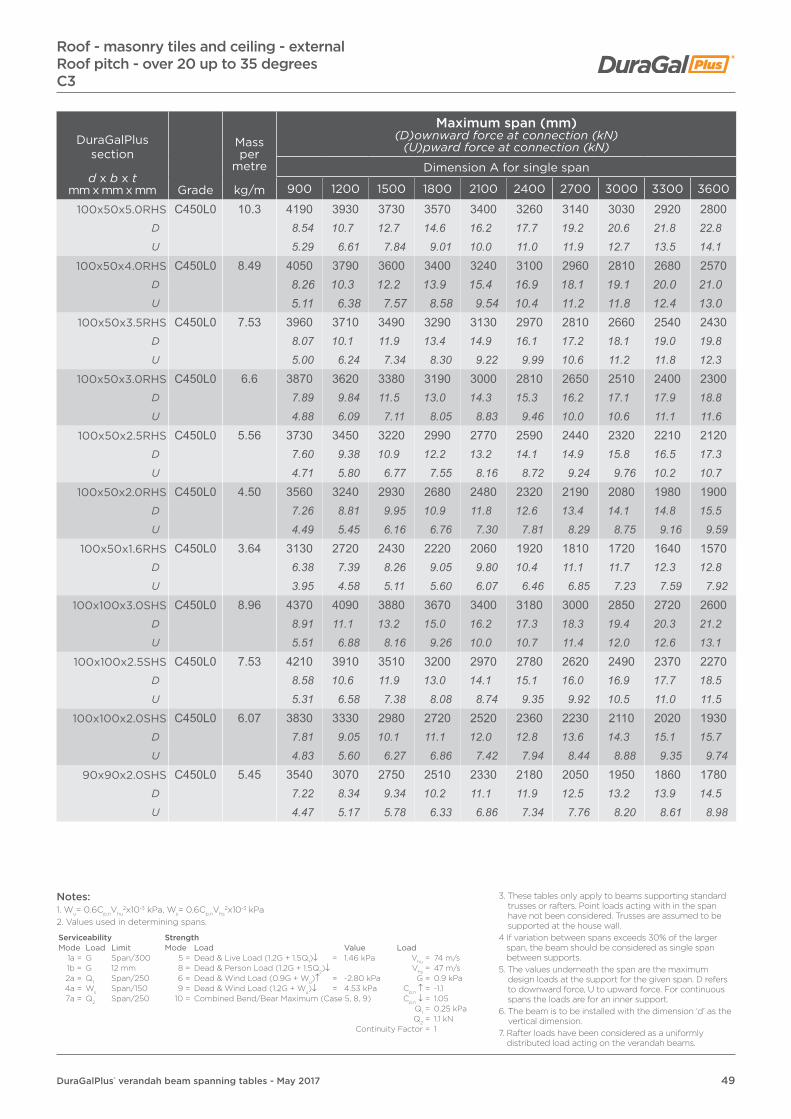
49DuraGalPlus® verandah beam spanning tables - May 2017
DuraGalPlus section
d x b x tmm x mm x mm Grade
Mass per
metre
kg/m
Maximum span (mm)(D)ownward force at connection (kN)
(U)pward force at connection (kN)
Dimension A for single span
900 1200 1500 1800 2100 2400 2700 3000 3300 3600
100x50x5.0RHS C450L0 10.3 4190 3930 3730 3570 3400 3260 3140 3030 2920 2800D 8.54 10.7 12.7 14.6 16.2 17.7 19.2 20.6 21.8 22.8U 5.29 6.61 7.84 9.01 10.0 11.0 11.9 12.7 13.5 14.1
100x50x4.0RHS C450L0 8.49 4050 3790 3600 3400 3240 3100 2960 2810 2680 2570D 8.26 10.3 12.2 13.9 15.4 16.9 18.1 19.1 20.0 21.0U 5.11 6.38 7.57 8.58 9.54 10.4 11.2 11.8 12.4 13.0
100x50x3.5RHS C450L0 7.53 3960 3710 3490 3290 3130 2970 2810 2660 2540 2430D 8.07 10.1 11.9 13.4 14.9 16.1 17.2 18.1 19.0 19.8U 5.00 6.24 7.34 8.30 9.22 9.99 10.6 11.2 11.8 12.3
100x50x3.0RHS C450L0 6.6 3870 3620 3380 3190 3000 2810 2650 2510 2400 2300D 7.89 9.84 11.5 13.0 14.3 15.3 16.2 17.1 17.9 18.8U 4.88 6.09 7.11 8.05 8.83 9.46 10.0 10.6 11.1 11.6
100x50x2.5RHS C450L0 5.56 3730 3450 3220 2990 2770 2590 2440 2320 2210 2120D 7.60 9.38 10.9 12.2 13.2 14.1 14.9 15.8 16.5 17.3U 4.71 5.80 6.77 7.55 8.16 8.72 9.24 9.76 10.2 10.7
100x50x2.0RHS C450L0 4.50 3560 3240 2930 2680 2480 2320 2190 2080 1980 1900D 7.26 8.81 9.95 10.9 11.8 12.6 13.4 14.1 14.8 15.5U 4.49 5.45 6.16 6.76 7.30 7.81 8.29 8.75 9.16 9.59
100x50x1.6RHS C450L0 3.64 3130 2720 2430 2220 2060 1920 1810 1720 1640 1570D 6.38 7.39 8.26 9.05 9.80 10.4 11.1 11.7 12.3 12.8U 3.95 4.58 5.11 5.60 6.07 6.46 6.85 7.23 7.59 7.92
100x100x3.0SHS C450L0 8.96 4370 4090 3880 3670 3400 3180 3000 2850 2720 2600D 8.91 11.1 13.2 15.0 16.2 17.3 18.3 19.4 20.3 21.2U 5.51 6.88 8.16 9.26 10.0 10.7 11.4 12.0 12.6 13.1
100x100x2.5SHS C450L0 7.53 4210 3910 3510 3200 2970 2780 2620 2490 2370 2270D 8.58 10.6 11.9 13.0 14.1 15.1 16.0 16.9 17.7 18.5U 5.31 6.58 7.38 8.08 8.74 9.35 9.92 10.5 11.0 11.5
100x100x2.0SHS C450L0 6.07 3830 3330 2980 2720 2520 2360 2230 2110 2020 1930D 7.81 9.05 10.1 11.1 12.0 12.8 13.6 14.3 15.1 15.7U 4.83 5.60 6.27 6.86 7.42 7.94 8.44 8.88 9.35 9.74
90x90x2.0SHS C450L0 5.45 3540 3070 2750 2510 2330 2180 2050 1950 1860 1780D 7.22 8.34 9.34 10.2 11.1 11.9 12.5 13.2 13.9 14.5U 4.47 5.17 5.78 6.33 6.86 7.34 7.76 8.20 8.61 8.98
Roof - masonry tiles and ceiling - externalRoof pitch - over 20 up to 35 degreesC3
Notes:1. Wu= 0.6Cp,nVhu
2x10⁻³ kPa, Ws= 0.6Cp,nVhs2x10-3 kPa
2. Values used in determining spans.
Serviceability StrengthMode Load Limit Mode Load Value Load
1a = G Span/300 5 = Dead & Live Load (1.2G + 1.5Q1)↓ = 1.46 kPa Vhu = 74 m/s1b = G 12 mm 8 = Dead & Person Load (1.2G + 1.5Q2)↓ Vhs = 47 m/s2a = Q1 Span/250 6 = Dead & Wind Load (0.9G + Wu)↑ = -2.80 kPa G = 0.9 kPa4a = Ws Span/150 9 = Dead & Wind Load (1.2G + Wu)↓ = 4.53 kPa Cp,n ↑ = -1.17a = Q2 Span/250 10 = Combined Bend/Bear Maximum (Case 5, 8, 9) Cp,n ↓ = 1.05
Q1 = 0.25 kPaQ2 = 1.1 kN
Continuity Factor = 1
3. These tables only apply to beams supporting standard trusses or rafters. Point loads acting with in the span have not been considered. Trusses are assumed to be supported at the house wall.
4 If variation between spans exceeds 30% of the larger span, the beam should be considered as single span between supports.
5. The values underneath the span are the maximum design loads at the support for the given span. D refers to downward force, U to upward force. For continuous spans the loads are for an inner support.
6. The beam is to be installed with the dimension ‘d’ as the vertical dimension.
7. Rafter loads have been considered as a uniformly distributed load acting on the verandah beams.

50 DuraGalPlus® verandah beam spanning tables - May 2017
Roof - masonry tiles and ceiling - externalRoof pitch - over 20 up to 35 degrees
C3
DuraGalPlus section
d x b x tmm x mm x mm Grade
Mass per
metre
kg/m
Maximum span (mm)(D)ownward force at connection (kN)
(U)pward force at connection (kN)
Dimension A for continuous span
900 1200 1500 1800 2100 2400 2700 3000 3300 3600
150x50x6.0RHS C450L0 16.7 6930 6520 6210 5950 5520 5170 4870 4630 4420 4230D 35.3 44.3 52.7 60.6 65.6 70.3 74.5 78.7 82.6 86.2U 21.9 27.4 32.7 37.5 40.6 43.5 46.1 48.7 51.1 53.4
150x50x5.0RHS C450L0 14.2 6750 6340 6030 5540 5140 4810 4540 4310 4110 3940D 34.4 43.1 51.2 56.5 61.1 65.4 69.4 73.2 76.8 80.3U 21.3 26.7 31.7 35.0 37.8 40.5 43.0 45.3 47.5 49.7
150x50x4.0RHS C450L0 11.6 6510 5680 5040 4570 4200 3910 3660 3450 3270 3120D 33.2 38.6 42.8 46.6 49.9 53.1 56.0 58.6 61.1 63.6U 20.5 23.9 26.5 28.8 30.9 32.9 34.6 36.3 37.8 39.4
150x50x3.0RHS C450L0 8.96 5410 4590 4030 3620 3300 3040 2820 2640 2490 2350D 27.6 31.2 34.2 36.9 39.2 41.3 43.1 44.8 46.5 47.9U 17.1 19.3 21.2 22.8 24.3 25.6 26.7 27.8 28.8 29.7
150x50x2.5RHS C450L0 7.53 4560 3810 3310 2940 2650 2430 2240 2080 1940 1830D 23.2 25.9 28.1 30.0 31.5 33.0 34.2 35.3 36.3 37.3U 14.4 16.0 17.4 18.5 19.5 20.4 21.2 21.9 22.4 23.1
150x50x2.0RHS C450L0 6.07 3320 2720 2320 2030 1800 1630 1490 1370 1270 1180D 16.9 18.5 19.7 20.7 21.4 22.2 22.8 23.3 23.7 24.1U 10.5 11.4 12.2 12.8 13.2 13.7 14.1 14.4 14.7 14.9
125x75x6.0RHS C450L0 16.7 6600 6210 5830 5300 4890 4550 4270 4040 3830 3660D 33.6 42.2 49.5 54.0 58.1 61.8 65.3 68.6 71.6 74.6U 20.8 26.1 30.7 33.4 36.0 38.3 40.4 42.5 44.3 46.2
125x75x5.0RHS C450L0 14.2 6420 6030 5390 4890 4510 4190 3930 3710 3530 3360D 32.7 41.0 45.8 49.8 53.6 56.9 60.1 63.0 66.0 68.5U 20.3 25.4 28.3 30.9 33.2 35.2 37.2 39.0 40.8 42.4
125x75x4.0RHS C450L0 11.6 6190 5430 4820 4360 4010 3730 3490 3290 3120 2970D 31.5 36.9 40.9 44.4 47.7 50.7 53.4 55.9 58.3 60.5U 19.5 22.8 25.3 27.5 29.5 31.4 33.0 34.6 36.1 37.5
125x75x3.0RHS C450L0 8.96 5350 4570 4030 3630 3320 3070 2870 2690 2540 2410D 27.3 31.1 34.2 37.0 39.5 41.7 43.9 45.7 47.5 49.1
U 16.9 19.2 21.2 22.9 24.4 25.8 27.2 28.3 29.4 30.4
125x75x2.5RHS C450L0 7.53 4380 3710 3240 2910 2640 2430 2250 2110 1980 1870D 22.3 25.2 27.5 29.7 31.4 33.0 34.4 35.8 37.0 38.1U 13.8 15.6 17.0 18.4 19.4 20.4 21.3 22.2 22.9 23.6
125x75x2.0RHS C450L0 6.07 3320 2760 2390 2110 1900 1730 1590 1470 1370 1290D 16.9 18.8 20.3 21.5 22.6 23.5 24.3 25.0 25.6 26.3U 10.5 11.6 12.6 13.3 14.0 14.6 15.0 15.5 15.8 16.3
Notes:1. Wu= 0.6Cp,nVhu
2x10⁻³ kPa, Ws= 0.6Cp,nVhs2x10-3 kPa
2. Values used in determining spans.
Serviceability StrengthMode Load Limit Mode Load Value Load
1a = G Span/300 5 = Dead & Live Load (1.2G + 1.5Q1)↓ = 1.46 kPa Vhu = 74 m/s1b = G 12 mm 8 = Dead & Person Load (1.2G + 1.5Q2)↓ Vhs = 47 m/s2a = Q1 Span/250 6 = Dead & Wind Load (0.9G + Wu)↑ = -2.80 kPa G = 0.9 kPa4a = Ws Span/150 9 = Dead & Wind Load (1.2G + Wu)↓ = 4.53 kPa Cp,n ↑ = -1.17a = Q2 Span/250 10 = Combined Bend/Bear Maximum (Case 5, 8, 9) Cp,n ↓ = 1.05
Q1 = 0.25 kPaQ2 = 1.1 kN
Continuity Factor = 1
3. These tables only apply to beams supporting standard trusses or rafters. Point loads acting with in the span have not been considered. Trusses are assumed to be supported at the house wall.
4 If variation between spans exceeds 30% of the larger span, the beam should be considered as single span between supports.
5. The values underneath the span are the maximum design loads at the support for the given span. D refers to downward force, U to upward force. For continuous spans the loads are for an inner support.
6. The beam is to be installed with the dimension ‘d’ as the vertical dimension.
7. Rafter loads have been considered as a uniformly distributed load acting on the verandah beams.

51DuraGalPlus® verandah beam spanning tables - May 2017
Roof - masonry tiles and ceiling - externalRoof pitch - over 20 up to 35 degreesC3
DuraGalPlus section
d x b x tmm x mm x mm Grade
Mass per
metre
kg/m
Maximum span (mm)(D)ownward force at connection (kN)
(U)pward force at connection (kN)
Dimension A for continuous span
900 1200 1500 1800 2100 2400 2700 3000 3300 3600100x50x5.0RHS C450L0 10.3 5220 4810 4320 3950 3660 3420 3230 3070 2920 2800
D 26.6 32.7 36.7 40.3 43.5 46.5 49.4 52.2 54.6 57.1U 16.5 20.2 22.7 24.9 26.9 28.8 30.6 32.3 33.8 35.3
100x50x4.0RHS C450L0 8.49 5050 4420 3960 3620 3360 3140 2960 2810 2680 2570D 25.7 30.0 33.6 36.9 40.0 42.7 45.3 47.7 50.1 52.4U 15.9 18.6 20.8 22.8 24.7 26.4 28.0 29.5 31.0 32.4
100x50x3.5RHS C450L0 7.53 4830 4190 3750 3430 3180 2970 2810 2660 2540 2430D 24.6 28.5 31.9 35.0 37.8 40.4 43.0 45.2 47.5 49.5U 15.2 17.6 19.7 21.6 23.4 25.0 26.6 28.0 29.4 30.7
100x50x3.0RHS C450L0 6.6 4270 3670 3260 2950 2710 2520 2360 2230 2110 2010D 21.8 24.9 27.7 30.1 32.2 34.2 36.1 37.9 39.4 41.0U 13.5 15.4 17.1 18.6 19.9 21.2 22.3 23.4 24.4 25.4
100x50x2.5RHS C450L0 5.56 3800 3240 2870 2590 2370 2190 2050 1920 1820 1730D 19.4 22.0 24.4 26.4 28.2 29.8 31.3 32.6 34.0 35.3U 12.0 13.6 15.1 16.3 17.4 18.4 19.4 20.2 21.1 21.8
100x50x2.0RHS C450L0 4.50 3160 2670 2330 2090 1890 1740 1610 1510 1420 1340D 16.1 18.1 19.8 21.3 22.5 23.6 24.6 25.7 26.5 27.3U 9.97 11.2 12.3 13.2 13.9 14.6 15.2 15.9 16.4 16.9
100x50x1.6RHS C450L0 3.64 2350 1950 1680 1490 1340 1220 1120 1040 960 900D 12.0 13.2 14.3 15.2 15.9 16.6 17.1 17.7 17.9 18.3U 7.41 8.20 8.83 9.40 9.86 10.3 10.6 10.9 11.1 11.4
100x100x3.0SHS C450L0 8.96 4030 3370 2930 2600 2350 2140 1980 1840 1720 1610D 20.5 22.9 24.9 26.5 27.9 29.1 30.3 31.3 32.1 32.8U 12.7 14.2 15.4 16.4 17.3 18.0 18.7 19.3 19.9 20.3
100x100x2.5SHS C450L0 7.53 3630 3050 2660 2370 2140 1960 1820 1690 1580 1490D 18.5 20.7 22.6 24.2 25.4 26.6 27.8 28.7 29.5 30.4U 11.5 12.8 14.0 15.0 15.8 16.5 17.2 17.8 18.3 18.8
100x100x2.0SHS C450L0 6.07 3190 2690 2350 2100 1910 1760 1630 1520 1430 1350D 16.3 18.3 20.0 21.4 22.7 23.9 24.9 25.8 26.7 27.5U 10.1 11.3 12.4 13.2 14.1 14.8 15.4 16.0 16.5 17.0
90x90x2.0SHS C450L0 5.45 2990 2530 2210 1980 1800 1660 1540 1440 1350 1280D 15.2 17.2 18.8 20.2 21.4 22.6 23.5 24.5 25.2 26.1U 9.43 10.6 11.6 12.5 13.2 14.0 14.6 15.1 15.6 16.2
Notes:1. Wu= 0.6Cp,nVhu
2x10⁻³ kPa, Ws= 0.6Cp,nVhs2x10-3 kPa
2. Values used in determining spans.
Serviceability StrengthMode Load Limit Mode Load Value Load
1a = G Span/300 5 = Dead & Live Load (1.2G + 1.5Q1)↓ = 1.46 kPa Vhu = 74 m/s1b = G 12 mm 8 = Dead & Person Load (1.2G + 1.5Q2)↓ Vhs = 47 m/s2a = Q1 Span/250 6 = Dead & Wind Load (0.9G + Wu)↑ = -2.80 kPa G = 0.9 kPa4a = Ws Span/150 9 = Dead & Wind Load (1.2G + Wu)↓ = 4.53 kPa Cp,n ↑ = -1.17a = Q2 Span/250 10 = Combined Bend/Bear Maximum (Case 5, 8, 9) Cp,n ↓ = 1.05
Q1 = 0.25 kPaQ2 = 1.1 kN
Continuity Factor = 1
3. These tables only apply to beams supporting standard trusses or rafters. Point loads acting with in the span have not been considered. Trusses are assumed to be supported at the house wall.
4 If variation between spans exceeds 30% of the larger span, the beam should be considered as single span between supports.
5. The values underneath the span are the maximum design loads at the support for the given span. D refers to downward force, U to upward force. For continuous spans the loads are for an inner support.
6. The beam is to be installed with the dimension ‘d’ as the vertical dimension.
7. Rafter loads have been considered as a uniformly distributed load acting on the verandah beams.
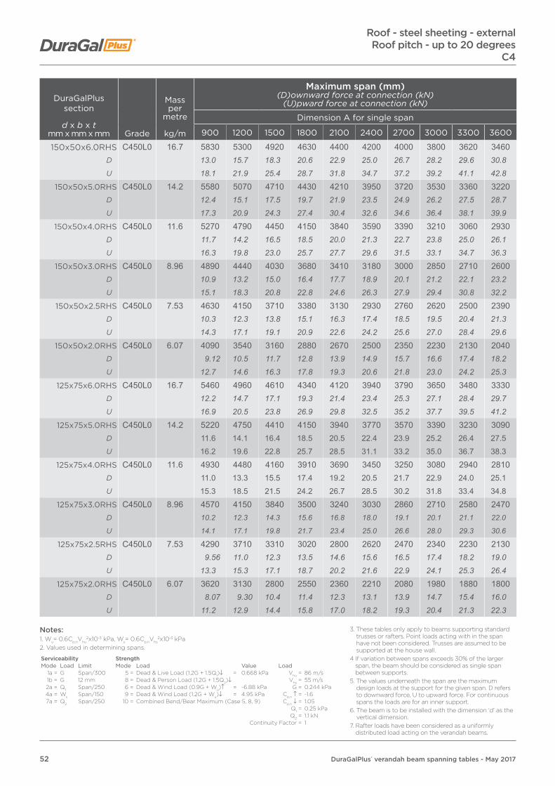
52 DuraGalPlus® verandah beam spanning tables - May 2017
DuraGalPlus section
d x b x tmm x mm x mm Grade
Mass per
metre
kg/m
Maximum span (mm)(D)ownward force at connection (kN)
(U)pward force at connection (kN)
Dimension A for single span
900 1200 1500 1800 2100 2400 2700 3000 3300 3600
150x50x6.0RHS C450L0 16.7 5830 5300 4920 4630 4400 4200 4000 3800 3620 3460D 13.0 15.7 18.3 20.6 22.9 25.0 26.7 28.2 29.6 30.8U 18.1 21.9 25.4 28.7 31.8 34.7 37.2 39.2 41.1 42.8
150x50x5.0RHS C450L0 14.2 5580 5070 4710 4430 4210 3950 3720 3530 3360 3220D 12.4 15.1 17.5 19.7 21.9 23.5 24.9 26.2 27.5 28.7U 17.3 20.9 24.3 27.4 30.4 32.6 34.6 36.4 38.1 39.9
150x50x4.0RHS C450L0 11.6 5270 4790 4450 4150 3840 3590 3390 3210 3060 2930D 11.7 14.2 16.5 18.5 20.0 21.3 22.7 23.8 25.0 26.1U 16.3 19.8 23.0 25.7 27.7 29.6 31.5 33.1 34.7 36.3
150x50x3.0RHS C450L0 8.96 4890 4440 4030 3680 3410 3180 3000 2850 2710 2600D 10.9 13.2 15.0 16.4 17.7 18.9 20.1 21.2 22.1 23.2U 15.1 18.3 20.8 22.8 24.6 26.3 27.9 29.4 30.8 32.2
150x50x2.5RHS C450L0 7.53 4630 4150 3710 3380 3130 2930 2760 2620 2500 2390D 10.3 12.3 13.8 15.1 16.3 17.4 18.5 19.5 20.4 21.3U 14.3 17.1 19.1 20.9 22.6 24.2 25.6 27.0 28.4 29.6
150x50x2.0RHS C450L0 6.07 4090 3540 3160 2880 2670 2500 2350 2230 2130 2040D 9.12 10.5 11.7 12.8 13.9 14.9 15.7 16.6 17.4 18.2U 12.7 14.6 16.3 17.8 19.3 20.6 21.8 23.0 24.2 25.3
125x75x6.0RHS C450L0 16.7 5460 4960 4610 4340 4120 3940 3790 3650 3480 3330D 12.2 14.7 17.1 19.3 21.4 23.4 25.3 27.1 28.4 29.7U 16.9 20.5 23.8 26.9 29.8 32.5 35.2 37.7 39.5 41.2
125x75x5.0RHS C450L0 14.2 5220 4750 4410 4150 3940 3770 3570 3390 3230 3090D 11.6 14.1 16.4 18.5 20.5 22.4 23.9 25.2 26.4 27.5U 16.2 19.6 22.8 25.7 28.5 31.1 33.2 35.0 36.7 38.3
125x75x4.0RHS C450L0 11.6 4930 4480 4160 3910 3690 3450 3250 3080 2940 2810D 11.0 13.3 15.5 17.4 19.2 20.5 21.7 22.9 24.0 25.1U 15.3 18.5 21.5 24.2 26.7 28.5 30.2 31.8 33.4 34.8
125x75x3.0RHS C450L0 8.96 4570 4150 3840 3500 3240 3030 2860 2710 2580 2470D 10.2 12.3 14.3 15.6 16.8 18.0 19.1 20.1 21.1 22.0
U 14.1 17.1 19.8 21.7 23.4 25.0 26.6 28.0 29.3 30.6
125x75x2.5RHS C450L0 7.53 4290 3710 3310 3020 2800 2620 2470 2340 2230 2130D 9.56 11.0 12.3 13.5 14.6 15.6 16.5 17.4 18.2 19.0U 13.3 15.3 17.1 18.7 20.2 21.6 22.9 24.1 25.3 26.4
125x75x2.0RHS C450L0 6.07 3620 3130 2800 2550 2360 2210 2080 1980 1880 1800D 8.07 9.30 10.4 11.4 12.3 13.1 13.9 14.7 15.4 16.0U 11.2 12.9 14.4 15.8 17.0 18.2 19.3 20.4 21.3 22.3
Roof - steel sheeting - externalRoof pitch - up to 20 degrees
C4
Notes:1. Wu= 0.6Cp,nVhu
2x10⁻³ kPa, Ws= 0.6Cp,nVhs2x10-3 kPa
2. Values used in determining spans.
Serviceability StrengthMode Load Limit Mode Load Value Load
1a = G Span/300 5 = Dead & Live Load (1.2G + 1.5Q1)↓ = 0.668 kPa Vhu = 86 m/s1b = G 12 mm 8 = Dead & Person Load (1.2G + 1.5Q2)↓ Vhs = 55 m/s2a = Q1 Span/250 6 = Dead & Wind Load (0.9G + Wu)↑ = -6.88 kPa G = 0.244 kPa4a = Ws Span/150 9 = Dead & Wind Load (1.2G + Wu)↓ = 4.95 kPa Cp,n ↑ = -1.67a = Q2 Span/250 10 = Combined Bend/Bear Maximum (Case 5, 8, 9) Cp,n ↓ = 1.05
Q1 = 0.25 kPaQ2 = 1.1 kN
Continuity Factor = 1
3. These tables only apply to beams supporting standard trusses or rafters. Point loads acting with in the span have not been considered. Trusses are assumed to be supported at the house wall.
4 If variation between spans exceeds 30% of the larger span, the beam should be considered as single span between supports.
5. The values underneath the span are the maximum design loads at the support for the given span. D refers to downward force, U to upward force. For continuous spans the loads are for an inner support.
6. The beam is to be installed with the dimension ‘d’ as the vertical dimension.
7. Rafter loads have been considered as a uniformly distributed load acting on the verandah beams.

53DuraGalPlus® verandah beam spanning tables - May 2017
DuraGalPlus section
d x b x tmm x mm x mm Grade
Mass per
metre
kg/m
Maximum span (mm)(D)ownward force at connection (kN)
(U)pward force at connection (kN)
Dimension A for single span
900 1200 1500 1800 2100 2400 2700 3000 3300 3600
100x50x5.0RHS C450L0 10.3 3910 3550 3300 3100 2950 2800 2640 2500 2390 2280D 8.71 10.5 12.3 13.8 15.3 16.6 17.7 18.6 19.5 20.3U 12.1 14.7 17.0 19.2 21.3 23.1 24.5 25.8 27.1 28.2
100x50x4.0RHS C450L0 8.49 3710 3370 3130 2950 2740 2570 2420 2290 2190 2090D 8.27 10.0 11.6 13.1 14.2 15.3 16.2 17.0 17.9 18.6U 11.5 13.9 16.2 18.3 19.8 21.2 22.5 23.6 24.9 25.9
100x50x3.5RHS C450L0 7.53 3590 3260 3030 2810 2600 2430 2290 2170 2070 1980D 8.00 9.69 11.3 12.5 13.5 14.4 15.3 16.1 16.9 17.7U 11.1 13.5 15.6 17.4 18.8 20.1 21.3 22.4 23.5 24.5
100x50x3.0RHS C450L0 6.6 3470 3150 2900 2650 2450 2290 2160 2050 1950 1870D 7.73 9.36 10.8 11.8 12.7 13.6 14.4 15.2 15.9 16.7U 10.7 13.0 15.0 16.4 17.7 18.9 20.1 21.2 22.1 23.2
100x50x2.5RHS C450L0 5.56 3290 2990 2670 2440 2260 2110 1990 1890 1800 1720D 7.33 8.89 9.92 10.9 11.8 12.5 13.3 14.0 14.7 15.3U 10.2 12.3 13.8 15.1 16.3 17.4 18.5 19.5 20.4 21.3
100x50x2.0RHS C450L0 4.50 3090 2680 2400 2190 2020 1890 1780 1690 1610 1540D 6.89 7.96 8.91 9.76 10.5 11.2 11.9 12.6 13.2 13.7U 9.57 11.1 12.4 13.6 14.6 15.6 16.5 17.4 18.3 19.1
100x50x1.6RHS C450L0 3.64 2560 2220 1980 1810 1670 1570 1480 1400 1330 1280D 5.71 6.60 7.35 8.07 8.68 9.33 9.90 10.4 10.9 11.4U 7.93 9.16 10.2 11.2 12.1 13.0 13.7 14.4 15.1 15.9
100x100x3.0SHS C450L0 8.96 4110 3690 3300 3010 2780 2600 2450 2330 2220 2120D 9.16 11.0 12.3 13.4 14.5 15.5 16.4 17.3 18.1 18.9U 12.7 15.2 17.0 18.6 20.1 21.5 22.8 24.0 25.2 26.3
100x100x2.5SHS C450L0 7.53 3720 3210 2870 2620 2430 2270 2140 2030 1930 1850D 8.29 9.54 10.7 11.7 12.6 13.5 14.3 15.1 15.8 16.5U 11.5 13.3 14.8 16.2 17.6 18.7 19.9 21.0 21.9 22.9
100x100x2.0SHS C450L0 6.07 3150 2730 2440 2220 2060 1930 1810 1720 1640 1570D 7.02 8.11 9.06 9.90 10.7 11.5 12.1 12.8 13.4 14.0U 9.75 11.3 12.6 13.7 14.9 15.9 16.8 17.8 18.6 19.4
90x90x2.0SHS C450L0 5.45 2900 2510 2250 2050 1900 1770 1670 1590 1510 1450D 6.46 7.46 8.36 9.14 9.88 10.5 11.2 11.8 12.3 12.9U 8.98 10.4 11.6 12.7 13.7 14.6 15.5 16.4 17.1 18.0
Roof - steel sheeting - externalRoof pitch - up to 20 degreesC4
Notes:1. Wu= 0.6Cp,nVhu
2x10⁻³ kPa, Ws= 0.6Cp,nVhs2x10-3 kPa
2. Values used in determining spans.
Serviceability StrengthMode Load Limit Mode Load Value Load
1a = G Span/300 5 = Dead & Live Load (1.2G + 1.5Q1)↓ = 0.668 kPa Vhu = 86 m/s1b = G 12 mm 8 = Dead & Person Load (1.2G + 1.5Q2)↓ Vhs = 55 m/s2a = Q1 Span/250 6 = Dead & Wind Load (0.9G + Wu)↑ = -6.88 kPa G = 0.244 kPa4a = Ws Span/150 9 = Dead & Wind Load (1.2G + Wu)↓ = 4.95 kPa Cp,n ↑ = -1.67a = Q2 Span/250 10 = Combined Bend/Bear Maximum (Case 5, 8, 9) Cp,n ↓ = 1.05
Q1 = 0.25 kPaQ2 = 1.1 kN
Continuity Factor = 1
3. These tables only apply to beams supporting standard trusses or rafters. Point loads acting with in the span have not been considered. Trusses are assumed to be supported at the house wall.
4 If variation between spans exceeds 30% of the larger span, the beam should be considered as single span between supports.
5. The values underneath the span are the maximum design loads at the support for the given span. D refers to downward force, U to upward force. For continuous spans the loads are for an inner support.
6. The beam is to be installed with the dimension ‘d’ as the vertical dimension.
7. Rafter loads have been considered as a uniformly distributed load acting on the verandah beams.

54 DuraGalPlus® verandah beam spanning tables - May 2017
Roof - steel sheeting - externalRoof pitch - up to 20 degrees
C4
DuraGalPlus section
d x b x tmm x mm x mm Grade
Mass per
metre
kg/m
Maximum span (mm)(D)ownward force at connection (kN)
(U)pward force at connection (kN)
Dimension A for continuous span
900 1200 1500 1800 2100 2400 2700 3000 3300 3600
150x50x6.0RHS C450L0 16.7 6990 6040 5390 4910 4540 4250 4000 3800 3620 3460D 38.9 44.9 50.1 54.7 59.0 63.1 66.9 70.6 74.0 77.1U 54.1 62.3 69.5 76.0 82.0 87.7 92.9 98.0 102.7 107.1
150x50x5.0RHS C450L0 14.2 6490 5610 5010 4570 4220 3950 3720 3530 3360 3220D 36.2 41.7 46.5 50.9 54.9 58.7 62.2 65.6 68.6 71.8U 50.2 57.9 64.6 70.7 76.2 81.5 86.4 91.1 95.4 99.7
150x50x4.0RHS C450L0 11.6 5900 5100 4560 4150 3840 3590 3390 3210 3060 2930D 32.9 37.9 42.3 46.2 49.9 53.3 56.7 59.6 62.5 65.3U 45.7 52.6 58.8 64.2 69.4 74.1 78.7 82.8 86.8 90.7
150x50x3.0RHS C450L0 8.96 5150 4360 3830 3430 3120 2880 2670 2500 2350 2220D 28.7 32.4 35.6 38.2 40.6 42.8 44.6 46.4 48.0 49.5U 39.9 45.0 49.4 53.1 56.3 59.4 62.0 64.5 66.7 68.7
150x50x2.5RHS C450L0 7.53 4310 3610 3120 2770 2500 2280 2100 1950 1820 1710D 24.0 26.8 29.0 30.9 32.5 33.9 35.1 36.2 37.2 38.1U 33.4 37.3 40.2 42.9 45.2 47.1 48.8 50.3 51.7 52.9
150x50x2.0RHS C450L0 6.07 3130 2550 2170 1900 1690 1520 1380 1270 1180 1100D 17.4 18.9 20.2 21.2 22.0 22.6 23.1 23.6 24.1 24.5U 24.2 26.3 28.0 29.4 30.5 31.4 32.0 32.8 33.5 34.1
125x75x6.0RHS C450L0 16.7 6720 5800 5180 4720 4370 4080 3850 3650 3480 3330D 37.4 43.1 48.1 52.6 56.8 60.6 64.4 67.8 71.1 74.2U 52.0 59.9 66.8 73.1 78.9 84.2 89.4 94.2 98.8 103.1
125x75x5.0RHS C450L0 14.2 6230 5380 4810 4380 4060 3790 3570 3390 3230 3090D 34.7 40.0 44.7 48.8 52.8 56.3 59.7 63.0 66.0 68.9U 48.2 55.5 62.1 67.8 73.3 78.2 82.9 87.5 91.7 95.7
125x75x4.0RHS C450L0 11.6 5660 4890 4370 3990 3690 3450 3250 3080 2940 2810D 31.5 36.3 40.6 44.5 48.0 51.3 54.3 57.2 60.1 62.6U 43.8 50.5 56.4 61.8 66.6 71.2 75.5 79.5 83.4 87.0
125x75x3.0RHS C450L0 8.96 4970 4290 3830 3450 3150 2920 2720 2550 2410 2280D 27.7 31.9 35.6 38.4 41.0 43.4 45.5 47.4 49.2 50.8
U 38.5 44.3 49.4 53.4 56.9 60.3 63.2 65.8 68.4 70.6
125x75x2.5RHS C450L0 7.53 4160 3510 3070 2750 2500 2300 2130 1990 1870 1760D 23.2 26.1 28.5 30.6 32.5 34.2 35.6 37.0 38.2 39.2U 32.2 36.2 39.6 42.6 45.2 47.5 49.5 51.3 53.1 54.5
125x75x2.0RHS C450L0 6.07 3140 2610 2250 1990 1780 1620 1490 1380 1290 1210D 17.5 19.4 20.9 22.2 23.1 24.1 24.9 25.6 26.4 27.0U 24.3 26.9 29.0 30.8 32.1 33.4 34.6 35.6 36.6 37.5
Notes:1. Wu= 0.6Cp,nVhu
2x10⁻³ kPa, Ws= 0.6Cp,nVhs2x10-3 kPa
2. Values used in determining spans.
Serviceability StrengthMode Load Limit Mode Load Value Load
1a = G Span/300 5 = Dead & Live Load (1.2G + 1.5Q1)↓ = 0.668 kPa Vhu = 86 m/s1b = G 12 mm 8 = Dead & Person Load (1.2G + 1.5Q2)↓ Vhs = 55 m/s2a = Q1 Span/250 6 = Dead & Wind Load (0.9G + Wu)↑ = -6.88 kPa G = 0.244 kPa4a = Ws Span/150 9 = Dead & Wind Load (1.2G + Wu)↓ = 4.95 kPa Cp,n ↑ = -1.67a = Q2 Span/250 10 = Combined Bend/Bear Maximum (Case 5, 8, 9) Cp,n ↓ = 1.05
Q1 = 0.25 kPaQ2 = 1.1 kN
Continuity Factor = 1
3. These tables only apply to beams supporting standard trusses or rafters. Point loads acting with in the span have not been considered. Trusses are assumed to be supported at the house wall.
4 If variation between spans exceeds 30% of the larger span, the beam should be considered as single span between supports.
5. The values underneath the span are the maximum design loads at the support for the given span. D refers to downward force, U to upward force. For continuous spans the loads are for an inner support.
6. The beam is to be installed with the dimension ‘d’ as the vertical dimension.
7. Rafter loads have been considered as a uniformly distributed load acting on the verandah beams.

55DuraGalPlus® verandah beam spanning tables - May 2017
Roof - steel sheeting - externalRoof pitch - up to 20 degreesC4
DuraGalPlus section
d x b x tmm x mm x mm Grade
Mass per
metre
kg/m
Maximum span (mm)(D)ownward force at connection (kN)
(U)pward force at connection (kN)
Dimension A for continuous span
900 1200 1500 1800 2100 2400 2700 3000 3300 3600100x50x5.0RHS C450L0 10.3 4600 3970 3550 3240 3000 2800 2640 2500 2390 2280
D 25.6 29.5 33.0 36.1 39.0 41.6 44.1 46.4 48.8 50.8U 35.6 41.0 45.8 50.2 54.2 57.8 61.3 64.5 67.8 70.6
100x50x4.0RHS C450L0 8.49 4210 3640 3250 2970 2740 2570 2420 2290 2190 2090D 23.5 27.0 30.2 33.1 35.6 38.2 40.5 42.5 44.7 46.6U 32.6 37.6 41.9 46.0 49.5 53.0 56.2 59.1 62.2 64.7
100x50x3.5RHS C450L0 7.53 3980 3440 3080 2810 2600 2430 2290 2170 2070 1980D 22.2 25.6 28.6 31.3 33.8 36.1 38.3 40.3 42.3 44.1U 30.8 35.5 39.7 43.5 47.0 50.2 53.2 56.0 58.7 61.3
100x50x3.0RHS C450L0 6.6 3750 3250 2900 2650 2450 2290 2160 2050 1950 1870D 20.9 24.1 26.9 29.5 31.9 34.0 36.1 38.1 39.8 41.7U 29.0 33.5 37.4 41.0 44.2 47.3 50.2 52.9 55.3 57.9
100x50x2.5RHS C450L0 5.56 3460 2990 2670 2440 2250 2080 1940 1830 1720 1640D 19.3 22.2 24.8 27.2 29.3 30.9 32.4 34.0 35.1 36.6U 26.8 30.9 34.4 37.8 40.6 42.9 45.0 47.2 48.8 50.8
100x50x2.0RHS C450L0 4.50 3000 2530 2210 1970 1790 1640 1520 1420 1330 1260D 16.7 18.8 20.5 22.0 23.3 24.4 25.4 26.4 27.2 28.1U 23.2 26.1 28.5 30.5 32.3 33.9 35.3 36.6 37.7 39.0
100x50x1.6RHS C450L0 3.64 2220 1840 1580 1400 1260 1140 1050 970 900 850D 12.4 13.7 14.7 15.6 16.4 16.9 17.6 18.0 18.4 18.9U 17.2 19.0 20.4 21.7 22.8 23.5 24.4 25.0 25.5 26.3
100x100x3.0SHS C450L0 8.96 3810 3190 2760 2450 2210 2020 1860 1720 1610 1510D 21.2 23.7 25.6 27.3 28.7 30.0 31.1 31.9 32.9 33.7U 29.5 32.9 35.6 37.9 39.9 41.7 43.2 44.4 45.7 46.8
100x100x2.5SHS C450L0 7.53 3440 2890 2510 2240 2020 1850 1710 1590 1490 1400D 19.2 21.5 23.3 25.0 26.3 27.5 28.6 29.5 30.4 31.2U 26.6 29.8 32.4 34.7 36.5 38.2 39.7 41.0 42.3 43.3
100x100x2.0SHS C450L0 6.07 3030 2550 2230 1990 1810 1660 1540 1430 1340 1270D 16.9 18.9 20.7 22.2 23.5 24.7 25.7 26.6 27.4 28.3U 23.5 26.3 28.8 30.8 32.7 34.3 35.8 36.9 38.0 39.3
90x90x2.0SHS C450L0 5.45 2840 2400 2100 1870 1700 1560 1450 1360 1270 1200D 15.8 17.8 19.5 20.8 22.1 23.2 24.2 25.3 25.9 26.7U 22.0 24.8 27.1 28.9 30.7 32.2 33.7 35.1 36.0 37.2
Notes:1. Wu= 0.6Cp,nVhu
2x10⁻³ kPa, Ws= 0.6Cp,nVhs2x10-3 kPa
2. Values used in determining spans.
Serviceability StrengthMode Load Limit Mode Load Value Load
1a = G Span/300 5 = Dead & Live Load (1.2G + 1.5Q1)↓ = 0.668 kPa Vhu = 86 m/s1b = G 12 mm 8 = Dead & Person Load (1.2G + 1.5Q2)↓ Vhs = 55 m/s2a = Q1 Span/250 6 = Dead & Wind Load (0.9G + Wu)↑ = -6.88 kPa G = 0.244 kPa4a = Ws Span/150 9 = Dead & Wind Load (1.2G + Wu)↓ = 4.95 kPa Cp,n ↑ = -1.67a = Q2 Span/250 10 = Combined Bend/Bear Maximum (Case 5, 8, 9) Cp,n ↓ = 1.05
Q1 = 0.25 kPaQ2 = 1.1 kN
Continuity Factor = 1
3. These tables only apply to beams supporting standard trusses or rafters. Point loads acting with in the span have not been considered. Trusses are assumed to be supported at the house wall.
4 If variation between spans exceeds 30% of the larger span, the beam should be considered as single span between supports.
5. The values underneath the span are the maximum design loads at the support for the given span. D refers to downward force, U to upward force. For continuous spans the loads are for an inner support.
6. The beam is to be installed with the dimension ‘d’ as the vertical dimension.
7. Rafter loads have been considered as a uniformly distributed load acting on the verandah beams.

56 DuraGalPlus® verandah beam spanning tables - May 2017
DuraGalPlus section
d x b x tmm x mm x mm Grade
Mass per
metre
kg/m
Maximum span (mm)(D)ownward force at connection (kN)
(U)pward force at connection (kN)
Dimension A for single span
900 1200 1500 1800 2100 2400 2700 3000 3300 3600
150x50x6.0RHS C450L0 16.7 5560 5230 4920 4630 4400 4200 4040 3900 3780 3620D 14.4 18.0 21.2 23.9 26.5 28.9 31.3 33.6 35.8 37.4U 15.7 19.7 23.2 26.2 29.1 31.7 34.3 36.8 39.2 41.0
150x50x5.0RHS C450L0 14.2 5420 5070 4710 4430 4210 4030 3870 3690 3520 3370D 14.0 17.5 20.3 22.9 25.4 27.8 30.0 31.8 33.3 34.8U 15.3 19.1 22.2 25.1 27.8 30.4 32.9 34.8 36.5 38.2
150x50x4.0RHS C450L0 11.6 5220 4790 4450 4180 3970 3760 3540 3360 3200 3070D 13.5 16.5 19.2 21.6 23.9 25.9 27.4 28.9 30.3 31.7U 14.8 18.1 21.0 23.7 26.2 28.4 30.1 31.7 33.2 34.8
150x50x3.0RHS C450L0 8.96 4890 4440 4120 3850 3560 3330 3140 2980 2840 2720D 12.6 15.3 17.7 19.9 21.5 22.9 24.3 25.7 26.9 28.1U 13.8 16.8 19.4 21.8 23.5 25.1 26.7 28.1 29.5 30.8
150x50x2.5RHS C450L0 7.53 4630 4210 3880 3540 3280 3060 2890 2740 2610 2500D 12.0 14.5 16.7 18.3 19.8 21.1 22.4 23.6 24.7 25.8U 13.1 15.9 18.3 20.0 21.7 23.1 24.5 25.9 27.1 28.3
150x50x2.0RHS C450L0 6.07 4280 3700 3310 3020 2790 2610 2460 2330 2230 2130D 11.1 12.7 14.2 15.6 16.8 18.0 19.1 20.1 21.1 22.0U 12.1 14.0 15.6 17.1 18.4 19.7 20.9 22.0 23.1 24.1
125x75x6.0RHS C450L0 16.7 5300 4960 4610 4340 4120 3940 3790 3660 3540 3440D 13.7 17.1 19.8 22.4 24.8 27.1 29.4 31.5 33.5 35.5U 15.0 18.7 21.7 24.6 27.2 29.7 32.2 34.5 36.7 38.9
125x75x5.0RHS C450L0 14.2 5160 4750 4410 4150 3940 3770 3620 3500 3380 3240D 13.3 16.4 19.0 21.4 23.7 26.0 28.0 30.1 32.0 33.5U 14.6 17.9 20.8 23.5 26.0 28.5 30.7 33.0 35.1 36.7
125x75x4.0RHS C450L0 11.6 4930 4480 4160 3910 3720 3550 3400 3230 3070 2940D 12.7 15.4 17.9 20.2 22.4 24.5 26.3 27.8 29.1 30.4U 14.0 16.9 19.6 22.1 24.6 26.8 28.9 30.5 31.9 33.3
125x75x3.0RHS C450L0 8.96 4570 4150 3850 3620 3390 3170 2990 2830 2700 2580D 11.8 14.3 16.6 18.7 20.4 21.8 23.2 24.4 25.6 26.7
U 12.9 15.7 18.2 20.5 22.4 23.9 25.4 26.7 28.0 29.2
125x75x2.5RHS C450L0 7.53 4330 3880 3470 3160 2930 2740 2580 2450 2330 2230D 11.2 13.4 14.9 16.3 17.7 18.9 20.0 21.1 22.1 23.0U 12.3 14.6 16.4 17.9 19.4 20.7 21.9 23.1 24.2 25.2
125x75x2.0RHS C450L0 6.07 3790 3280 2930 2670 2470 2310 2180 2070 1970 1890D 9.79 11.3 12.6 13.8 14.9 15.9 16.9 17.8 18.7 19.5U 10.7 12.4 13.8 15.1 16.3 17.4 18.5 19.5 20.4 21.4
Roof - masonry tiles and ceiling - externalRoof pitch - up to 20 degrees
C4
Notes:1. Wu= 0.6Cp,nVhu
2x10⁻³ kPa, Ws= 0.6Cp,nVhs2x10-3 kPa
2. Values used in determining spans.
Serviceability StrengthMode Load Limit Mode Load Value Load
1a = G Span/300 5 = Dead & Live Load (1.2G + 1.5Q1)↓ = 1.46 kPa Vhu = 86 m/s1b = G 12 mm 8 = Dead & Person Load (1.2G + 1.5Q2)↓ Vhs = 55 m/s2a = Q1 Span/250 6 = Dead & Wind Load (0.9G + Wu)↑ = -6.29 kPa G = 0.9 kPa4a = Ws Span/150 9 = Dead & Wind Load (1.2G + Wu)↓ = 5.74 kPa Cp,n ↑ = -1.67a = Q2 Span/250 10 = Combined Bend/Bear Maximum (Case 5, 8, 9) Cp,n ↓ = 1.05
Q1 = 0.25 kPaQ2 = 1.1 kN
Continuity Factor = 1
3. These tables only apply to beams supporting standard trusses or rafters. Point loads acting with in the span have not been considered. Trusses are assumed to be supported at the house wall.
4 If variation between spans exceeds 30% of the larger span, the beam should be considered as single span between supports.
5. The values underneath the span are the maximum design loads at the support for the given span. D refers to downward force, U to upward force. For continuous spans the loads are for an inner support.
6. The beam is to be installed with the dimension ‘d’ as the vertical dimension.
7. Rafter loads have been considered as a uniformly distributed load acting on the verandah beams.

57DuraGalPlus® verandah beam spanning tables - May 2017
DuraGalPlus section
d x b x tmm x mm x mm Grade
Mass per
metre
kg/m
Maximum span (mm)(D)ownward force at connection (kN)
(U)pward force at connection (kN)
Dimension A for single span
900 1200 1500 1800 2100 2400 2700 3000 3300 3600
100x50x5.0RHS C450L0 10.3 3910 3550 3300 3100 2950 2820 2710 2620 2500 2390D 10.1 12.2 14.2 16.0 17.8 19.4 21.0 22.6 23.7 24.7U 11.1 13.4 15.6 17.5 19.5 21.3 23.0 24.7 25.9 27.1
100x50x4.0RHS C450L0 8.49 3710 3370 3130 2950 2800 2680 2530 2400 2290 2190D 9.58 11.6 13.5 15.2 16.9 18.5 19.6 20.7 21.7 22.6U 10.5 12.7 14.8 16.7 18.5 20.2 21.5 22.6 23.8 24.8
100x50x3.5RHS C450L0 7.53 3590 3260 3030 2850 2710 2540 2390 2270 2170 2070D 9.27 11.2 13.0 14.7 16.3 17.5 18.5 19.5 20.6 21.4U 10.2 12.3 14.3 16.1 17.9 19.2 20.3 21.4 22.5 23.4
100x50x3.0RHS C450L0 6.6 3470 3150 2930 2750 2560 2400 2260 2140 2040 1960D 8.96 10.8 12.6 14.2 15.4 16.5 17.5 18.4 19.3 20.2U 9.82 11.9 13.8 15.6 16.9 18.1 19.2 20.2 21.2 22.2
100x50x2.5RHS C450L0 5.56 3290 2990 2780 2550 2360 2210 2080 1980 1880 1800D 8.50 10.3 12.0 13.2 14.2 15.2 16.1 17.0 17.8 18.6U 9.31 11.3 13.1 14.4 15.6 16.7 17.7 18.7 19.5 20.4
100x50x2.0RHS C450L0 4.50 3090 2800 2510 2290 2120 1980 1870 1770 1690 1620D 7.98 9.64 10.8 11.8 12.8 13.6 14.5 15.2 16.0 16.7U 8.75 10.6 11.8 13.0 14.0 14.9 15.9 16.7 17.5 18.3
100x50x1.6RHS C450L0 3.64 2680 2320 2070 1890 1750 1640 1540 1460 1400 1340D 6.92 7.99 8.91 9.76 10.5 11.3 11.9 12.6 13.3 13.8U 7.59 8.76 9.77 10.7 11.6 12.4 13.1 13.8 14.5 15.2
100x100x3.0SHS C450L0 8.96 4110 3730 3450 3150 2910 2720 2570 2430 2320 2220D 10.6 12.8 14.9 16.3 17.5 18.7 19.9 20.9 22.0 22.9U 11.6 14.1 16.3 17.8 19.2 20.5 21.8 22.9 24.1 25.1
100x100x2.5SHS C450L0 7.53 3890 3360 3010 2740 2540 2370 2240 2120 2020 1940D 10.0 11.6 13.0 14.2 15.3 16.3 17.4 18.3 19.1 20.0U 11.0 12.7 14.2 15.5 16.8 17.9 19.0 20.0 21.0 22.0
100x100x2.0SHS C450L0 6.07 3300 2850 2550 2330 2150 2010 1900 1800 1720 1640D 8.52 9.81 11.0 12.0 13.0 13.8 14.7 15.5 16.3 16.9U 9.34 10.8 12.0 13.2 14.2 15.2 16.1 17.0 17.9 18.6
90x90x2.0SHS C450L0 5.45 3040 2630 2350 2140 1980 1860 1750 1660 1580 1510D 7.85 9.06 10.1 11.1 11.9 12.8 13.6 14.3 15.0 15.6U 8.60 9.93 11.1 12.1 13.1 14.0 14.9 15.7 16.4 17.1
Roof - masonry tiles and ceiling - externalRoof pitch - up to 20 degreesC4
Notes:1. Wu= 0.6Cp,nVhu
2x10⁻³ kPa, Ws= 0.6Cp,nVhs2x10-3 kPa
2. Values used in determining spans.
Serviceability StrengthMode Load Limit Mode Load Value Load
1a = G Span/300 5 = Dead & Live Load (1.2G + 1.5Q1)↓ = 1.46 kPa Vhu = 86 m/s1b = G 12 mm 8 = Dead & Person Load (1.2G + 1.5Q2)↓ Vhs = 55 m/s2a = Q1 Span/250 6 = Dead & Wind Load (0.9G + Wu)↑ = -6.29 kPa G = 0.9 kPa4a = Ws Span/150 9 = Dead & Wind Load (1.2G + Wu)↓ = 5.74 kPa Cp,n ↑ = -1.67a = Q2 Span/250 10 = Combined Bend/Bear Maximum (Case 5, 8, 9) Cp,n ↓ = 1.05
Q1 = 0.25 kPaQ2 = 1.1 kN
Continuity Factor = 1
3. These tables only apply to beams supporting standard trusses or rafters. Point loads acting with in the span have not been considered. Trusses are assumed to be supported at the house wall.
4 If variation between spans exceeds 30% of the larger span, the beam should be considered as single span between supports.
5. The values underneath the span are the maximum design loads at the support for the given span. D refers to downward force, U to upward force. For continuous spans the loads are for an inner support.
6. The beam is to be installed with the dimension ‘d’ as the vertical dimension.
7. Rafter loads have been considered as a uniformly distributed load acting on the verandah beams.

58 DuraGalPlus® verandah beam spanning tables - May 2017
Roof - masonry tiles and ceiling - externalRoof pitch - up to 20 degrees
C4
DuraGalPlus section
d x b x tmm x mm x mm Grade
Mass per
metre
kg/m
Maximum span (mm)(D)ownward force at connection (kN)
(U)pward force at connection (kN)
Dimension A for continuous span
900 1200 1500 1800 2100 2400 2700 3000 3300 3600
150x50x6.0RHS C450L0 16.7 6930 6320 5640 5140 4760 4440 4190 3970 3790 3620D 44.7 54.4 60.7 66.4 71.7 76.4 81.2 85.4 89.7 93.5U 49.0 59.6 66.5 72.7 78.6 83.8 89.0 93.6 98.3 102.5
150x50x5.0RHS C450L0 14.2 6750 5870 5240 4780 4420 4130 3890 3690 3520 3370D 43.6 50.5 56.4 61.7 66.6 71.1 75.4 79.4 83.3 87.0U 47.8 55.4 61.8 67.7 73.0 77.9 82.6 87.0 91.3 95.4
150x50x4.0RHS C450L0 11.6 5830 5010 4440 4020 3690 3430 3210 3020 2860 2720D 37.6 43.1 47.8 51.9 55.6 59.1 62.2 65.0 67.7 70.3U 41.3 47.3 52.4 56.9 60.9 64.7 68.1 71.2 74.2 77.0
150x50x3.0RHS C450L0 8.96 4730 4000 3500 3140 2850 2620 2430 2270 2140 2020D 30.5 34.4 37.7 40.5 42.9 45.1 47.1 48.9 50.7 52.2U 33.5 37.7 41.3 44.4 47.1 49.4 51.6 53.5 55.5 57.2
150x50x2.5RHS C450L0 7.53 3940 3280 2840 2510 2260 2060 1890 1760 1640 1540D 25.4 28.2 30.6 32.4 34.0 35.5 36.6 37.9 38.8 39.8U 27.9 30.9 33.5 35.5 37.3 38.9 40.1 41.5 42.6 43.6
150x50x2.0RHS C450L0 6.07 2820 2300 1950 1690 1500 1350 1230 1130 1040 970D 18.2 19.8 21.0 21.8 22.6 23.2 23.8 24.3 24.6 25.1U 20.0 21.7 23.0 23.9 24.8 25.5 26.1 26.7 27.0 27.5
125x75x6.0RHS C450L0 16.7 6600 5790 5150 4680 4310 4010 3760 3550 3370 3210D 42.6 49.8 55.4 60.4 64.9 69.0 72.8 76.4 79.8 82.9U 46.7 54.6 60.7 66.2 71.2 75.7 79.8 83.7 87.4 90.9
125x75x5.0RHS C450L0 14.2 6220 5350 4750 4310 3970 3690 3460 3260 3090 2940D 40.2 46.1 51.1 55.7 59.8 63.5 67.0 70.2 73.2 75.9U 44.0 50.5 56.0 61.0 65.6 69.6 73.5 76.9 80.2 83.2
125x75x4.0RHS C450L0 11.6 5580 4780 4240 3830 3520 3270 3050 2880 2720 2590D 36.0 41.2 45.6 49.5 53.0 56.3 59.1 62.0 64.4 66.9U 39.5 45.1 50.0 54.2 58.1 61.7 64.7 67.9 70.6 73.3
125x75x3.0RHS C450L0 8.96 4700 4000 3520 3170 2890 2670 2490 2330 2200 2080D 30.3 34.4 37.9 40.9 43.5 46.0 48.2 50.1 52.1 53.7
U 33.3 37.7 41.5 44.9 47.7 50.4 52.9 55.0 57.1 58.9
125x75x2.5RHS C450L0 7.53 3820 3220 2810 2510 2280 2090 1940 1810 1690 1600D 24.7 27.7 30.2 32.4 34.4 36.0 37.6 39.0 40.0 41.3U 27.0 30.4 33.1 35.5 37.6 39.4 41.2 42.7 43.9 45.3
125x75x2.0RHS C450L0 6.07 2860 2370 2030 1790 1610 1460 1340 1240 1150 1080D 18.5 20.4 21.8 23.1 24.3 25.1 26.0 26.7 27.2 27.9U 20.2 22.4 23.9 25.3 26.6 27.6 28.4 29.2 29.8 30.6
Notes:1. Wu= 0.6Cp,nVhu
2x10⁻³ kPa, Ws= 0.6Cp,nVhs2x10-3 kPa
2. Values used in determining spans.
Serviceability StrengthMode Load Limit Mode Load Value Load
1a = G Span/300 5 = Dead & Live Load (1.2G + 1.5Q1)↓ = 1.46 kPa Vhu = 86 m/s1b = G 12 mm 8 = Dead & Person Load (1.2G + 1.5Q2)↓ Vhs = 55 m/s2a = Q1 Span/250 6 = Dead & Wind Load (0.9G + Wu)↑ = -6.29 kPa G = 0.9 kPa4a = Ws Span/150 9 = Dead & Wind Load (1.2G + Wu)↓ = 5.74 kPa Cp,n ↑ = -1.67a = Q2 Span/250 10 = Combined Bend/Bear Maximum (Case 5, 8, 9) Cp,n ↓ = 1.05
Q1 = 0.25 kPaQ2 = 1.1 kN
Continuity Factor = 1
3. These tables only apply to beams supporting standard trusses or rafters. Point loads acting with in the span have not been considered. Trusses are assumed to be supported at the house wall.
4 If variation between spans exceeds 30% of the larger span, the beam should be considered as single span between supports.
5. The values underneath the span are the maximum design loads at the support for the given span. D refers to downward force, U to upward force. For continuous spans the loads are for an inner support.
6. The beam is to be installed with the dimension ‘d’ as the vertical dimension.
7. Rafter loads have been considered as a uniformly distributed load acting on the verandah beams.

59DuraGalPlus® verandah beam spanning tables - May 2017
Roof - masonry tiles and ceiling - externalRoof pitch - up to 20 degreesC4
DuraGalPlus section
d x b x tmm x mm x mm Grade
Mass per
metre
kg/m
Maximum span (mm)(D)ownward force at connection (kN)
(U)pward force at connection (kN)
Dimension A for continuous span
900 1200 1500 1800 2100 2400 2700 3000 3300 3600100x50x5.0RHS C450L0 10.3 4810 4160 3710 3390 3130 2930 2760 2620 2500 2390
D 31.1 35.8 39.9 43.8 47.2 50.5 53.5 56.4 59.2 61.7U 34.0 39.3 43.8 48.0 51.7 55.3 58.6 61.8 64.9 67.7
100x50x4.0RHS C450L0 8.49 4400 3810 3400 3100 2870 2680 2530 2400 2290 2190D 28.4 32.8 36.6 40.0 43.2 46.1 49.0 51.7 54.2 56.6U 31.1 35.9 40.1 43.9 47.4 50.6 53.7 56.6 59.4 62.0
100x50x3.5RHS C450L0 7.53 4160 3600 3220 2940 2720 2540 2390 2270 2170 2070D 26.9 31.0 34.7 38.0 41.0 43.7 46.3 48.9 51.4 53.5U 29.4 34.0 38.0 41.6 44.9 47.9 50.7 53.5 56.3 58.6
100x50x3.0RHS C450L0 6.6 3770 3230 2870 2590 2380 2210 2070 1950 1850 1760D 24.3 27.8 30.9 33.4 35.9 38.1 40.1 42.0 43.8 45.5U 26.7 30.5 33.8 36.7 39.3 41.7 43.9 46.0 48.0 49.8
100x50x2.5RHS C450L0 5.56 3340 2840 2510 2260 2060 1910 1780 1670 1580 1500D 21.6 24.5 27.0 29.2 31.0 32.9 34.5 35.9 37.4 38.7U 23.6 26.8 29.6 32.0 34.0 36.0 37.8 39.4 41.0 42.5
100x50x2.0RHS C450L0 4.50 2750 2310 2020 1800 1630 1490 1380 1290 1210 1140D 17.8 19.9 21.7 23.2 24.6 25.7 26.7 27.8 28.6 29.4U 19.5 21.8 23.8 25.5 26.9 28.1 29.3 30.4 31.4 32.3
100x50x1.6RHS C450L0 3.64 2020 1670 1430 1260 1130 1020 940 870 810 760D 13.0 14.4 15.4 16.3 17.0 17.6 18.2 18.7 19.2 19.6U 14.3 15.8 16.9 17.8 18.7 19.2 20.0 20.5 21.0 21.5
100x100x3.0SHS C450L0 8.96 3480 2900 2510 2220 2000 1820 1670 1550 1450 1360D 22.5 25.0 27.0 28.7 30.1 31.3 32.3 33.4 34.3 35.1U 24.6 27.4 29.6 31.4 33.0 34.3 35.5 36.6 37.6 38.5
100x100x2.5SHS C450L0 7.53 3150 2640 2290 2030 1830 1670 1540 1440 1340 1260D 20.3 22.7 24.6 26.2 27.6 28.8 29.8 31.0 31.7 32.5U 22.3 24.9 27.0 28.7 30.2 31.5 32.7 34.0 34.8 35.7
100x100x2.0SHS C450L0 6.07 2780 2340 2030 1810 1640 1510 1390 1300 1220 1150D 18.0 20.1 21.8 23.4 24.7 26.0 26.9 28.0 28.9 29.7U 19.7 22.1 23.9 25.6 27.1 28.5 29.5 30.7 31.7 32.6
90x90x2.0SHS C450L0 5.45 2600 2190 1910 1710 1550 1420 1320 1230 1150 1090D 16.8 18.9 20.6 22.1 23.4 24.5 25.6 26.5 27.2 28.2U 18.4 20.7 22.5 24.2 25.6 26.8 28.0 29.0 29.8 30.9
Notes:1. Wu= 0.6Cp,nVhu
2x10⁻³ kPa, Ws= 0.6Cp,nVhs2x10-3 kPa
2. Values used in determining spans.
Serviceability StrengthMode Load Limit Mode Load Value Load
1a = G Span/300 5 = Dead & Live Load (1.2G + 1.5Q1)↓ = 1.46 kPa Vhu = 86 m/s1b = G 12 mm 8 = Dead & Person Load (1.2G + 1.5Q2)↓ Vhs = 55 m/s2a = Q1 Span/250 6 = Dead & Wind Load (0.9G + Wu)↑ = -6.29 kPa G = 0.9 kPa4a = Ws Span/150 9 = Dead & Wind Load (1.2G + Wu)↓ = 5.74 kPa Cp,n ↑ = -1.67a = Q2 Span/250 10 = Combined Bend/Bear Maximum (Case 5, 8, 9) Cp,n ↓ = 1.05
Q1 = 0.25 kPaQ2 = 1.1 kN
Continuity Factor = 1
3. These tables only apply to beams supporting standard trusses or rafters. Point loads acting with in the span have not been considered. Trusses are assumed to be supported at the house wall.
4 If variation between spans exceeds 30% of the larger span, the beam should be considered as single span between supports.
5. The values underneath the span are the maximum design loads at the support for the given span. D refers to downward force, U to upward force. For continuous spans the loads are for an inner support.
6. The beam is to be installed with the dimension ‘d’ as the vertical dimension.
7. Rafter loads have been considered as a uniformly distributed load acting on the verandah beams.

60 DuraGalPlus® verandah beam spanning tables - May 2017
DuraGalPlus section
d x b x tmm x mm x mm Grade
Mass per
metre
kg/m
Maximum span (mm)(D)ownward force at connection (kN)
(U)pward force at connection (kN)
Dimension A for single span
900 1200 1500 1800 2100 2400 2700 3000 3300 3600
150x50x6.0RHS C450L0 16.7 6610 6000 5570 5240 4980 4760 4580 4420 4230 4050D 14.7 17.8 20.7 23.4 25.9 28.3 30.6 32.8 34.6 36.1U 13.9 16.8 19.5 22.0 24.4 26.6 28.8 30.9 32.5 34.0
150x50x5.0RHS C450L0 14.2 6330 5750 5340 5020 4770 4560 4340 4120 3930 3770D 14.1 17.1 19.8 22.4 24.8 27.1 29.0 30.6 32.1 33.6U 13.3 16.1 18.7 21.1 23.3 25.5 27.3 28.8 30.2 31.6
150x50x4.0RHS C450L0 11.6 5970 5430 5040 4740 4490 4200 3960 3760 3590 3440D 13.3 16.1 18.7 21.1 23.3 25.0 26.5 27.9 29.3 30.7U 12.5 15.2 17.6 19.9 22.0 23.5 24.9 26.3 27.6 28.9
150x50x3.0RHS C450L0 8.96 5540 5030 4670 4300 3980 3730 3520 3340 3180 3050D 12.3 14.9 17.3 19.2 20.7 22.2 23.5 24.8 26.0 27.2U 11.6 14.1 16.3 18.0 19.5 20.9 22.2 23.4 24.5 25.6
150x50x2.5RHS C450L0 7.53 5250 4770 4330 3960 3670 3430 3240 3070 2930 2810D 11.7 14.2 16.1 17.7 19.1 20.4 21.7 22.8 23.9 25.1U 11.0 13.3 15.1 16.6 18.0 19.2 20.4 21.5 22.5 23.6
150x50x2.0RHS C450L0 6.07 4760 4130 3700 3380 3130 2930 2760 2620 2500 2390D 10.6 12.3 13.7 15.1 16.3 17.4 18.5 19.5 20.4 21.3U 9.98 11.6 12.9 14.2 15.3 16.4 17.4 18.3 19.2 20.1
125x75x6.0RHS C450L0 16.7 6190 5620 5220 4910 4670 4460 4290 4140 4010 3890D 13.8 16.7 19.4 21.9 24.3 26.5 28.7 30.8 32.8 34.7U 13.0 15.7 18.2 20.6 22.9 24.9 27.0 28.9 30.8 32.6
125x75x5.0RHS C450L0 14.2 5920 5380 4990 4700 4460 4270 4100 3960 3780 3620D 13.2 16.0 18.5 21.0 23.2 25.4 27.4 29.4 30.9 32.3U 12.4 15.0 17.4 19.7 21.8 23.9 25.8 27.7 29.1 30.4
125x75x4.0RHS C450L0 11.6 5580 5070 4710 4430 4210 4030 3800 3610 3440 3300D 12.4 15.1 17.5 19.7 21.9 24.0 25.4 26.8 28.1 29.4U 11.7 14.2 16.5 18.6 20.6 22.5 23.9 25.2 26.5 27.7
125x75x3.0RHS C450L0 8.96 5170 4700 4360 4090 3790 3550 3340 3170 3030 2900D 11.5 14.0 16.2 18.2 19.7 21.1 22.3 23.6 24.8 25.9
U 10.8 13.1 15.2 17.2 18.6 19.9 21.0 22.2 23.3 24.3
125x75x2.5RHS C450L0 7.53 4900 4320 3870 3540 3280 3070 2890 2740 2620 2510D 10.9 12.8 14.4 15.8 17.1 18.2 19.3 20.4 21.4 22.4U 10.3 12.1 13.5 14.9 16.1 17.2 18.2 19.2 20.2 21.1
125x75x2.0RHS C450L0 6.07 4210 3660 3270 2990 2770 2590 2450 2320 2210 2120D 9.38 10.9 12.1 13.3 14.4 15.4 16.4 17.2 18.1 18.9U 8.83 10.2 11.4 12.5 13.6 14.5 15.4 16.2 17.0 17.8
Roof - steel sheeting - externalRoof pitch - over 20 up to 35 degrees
C4
Notes:1. Wu= 0.6Cp,nVhu
2x10⁻³ kPa, Ws= 0.6Cp,nVhs2x10-3 kPa
2. Values used in determining spans.
Serviceability StrengthMode Load Limit Mode Load Value Load
1a = G Span/300 5 = Dead & Live Load (1.2G + 1.5Q1)↓ = 0.668 kPa Vhu = 86 m/s1b = G 12 mm 8 = Dead & Person Load (1.2G + 1.5Q2)↓ Vhs = 55 m/s2a = Q1 Span/250 6 = Dead & Wind Load (0.9G + Wu)↑ = -4.66 kPa G = 0.244 kPa4a = Ws Span/150 9 = Dead & Wind Load (1.2G + Wu)↓ = 4.95 kPa Cp,n ↑ = -1.17a = Q2 Span/250 10 = Combined Bend/Bear Maximum (Case 5, 8, 9) Cp,n ↓ = 1.05
Q1 = 0.25 kPaQ2 = 1.1 kN
Continuity Factor = 1
3. These tables only apply to beams supporting standard trusses or rafters. Point loads acting with in the span have not been considered. Trusses are assumed to be supported at the house wall.
4 If variation between spans exceeds 30% of the larger span, the beam should be considered as single span between supports.
5. The values underneath the span are the maximum design loads at the support for the given span. D refers to downward force, U to upward force. For continuous spans the loads are for an inner support.
6. The beam is to be installed with the dimension ‘d’ as the vertical dimension.
7. Rafter loads have been considered as a uniformly distributed load acting on the verandah beams.

61DuraGalPlus® verandah beam spanning tables - May 2017
DuraGalPlus section
d x b x tmm x mm x mm Grade
Mass per
metre
kg/m
Maximum span (mm)(D)ownward force at connection (kN)
(U)pward force at connection (kN)
Dimension A for single span
900 1200 1500 1800 2100 2400 2700 3000 3300 3600
100x50x5.0RHS C450L0 10.3 4430 4030 3740 3520 3340 3200 3070 2930 2800 2680D 9.87 12.0 13.9 15.7 17.4 19.0 20.5 21.8 22.9 23.9U 9.29 11.3 13.1 14.8 16.3 17.9 19.3 20.5 21.5 22.5
100x50x4.0RHS C450L0 8.49 4210 3820 3550 3340 3170 3010 2830 2690 2570 2460D 9.38 11.4 13.2 14.9 16.5 17.9 18.9 20.0 21.0 21.9U 8.83 10.7 12.4 14.0 15.5 16.8 17.8 18.8 19.8 20.6
100x50x3.5RHS C450L0 7.53 4070 3700 3430 3230 3040 2850 2680 2550 2430 2330D 9.07 11.0 12.7 14.4 15.8 16.9 17.9 18.9 19.9 20.8U 8.54 10.3 12.0 13.6 14.9 15.9 16.9 17.8 18.7 19.5
100x50x3.0RHS C450L0 6.6 3930 3570 3310 3100 2870 2690 2530 2400 2290 2200D 8.76 10.6 12.3 13.8 14.9 16.0 16.9 17.8 18.7 19.6U 8.24 9.98 11.6 13.0 14.0 15.0 15.9 16.8 17.6 18.5
100x50x2.5RHS C450L0 5.56 3730 3390 3130 2860 2650 2480 2340 2220 2120 2030D 8.31 10.1 11.6 12.7 13.8 14.7 15.6 16.5 17.3 18.1U 7.82 9.48 10.9 12.0 13.0 13.9 14.7 15.5 16.3 17.0
100x50x2.0RHS C450L0 4.50 3500 3140 2810 2560 2380 2220 2100 1990 1900 1820D 7.80 9.33 10.4 11.4 12.4 13.2 14.0 14.8 15.5 16.2U 7.34 8.78 9.82 10.7 11.6 12.4 13.2 13.9 14.6 15.3
100x50x1.6RHS C450L0 3.64 3000 2600 2330 2120 1970 1840 1740 1650 1570 1500D 6.69 7.73 8.65 9.45 10.2 10.9 11.6 12.3 12.8 13.4U 6.29 7.27 8.15 8.89 9.64 10.3 10.9 11.5 12.1 12.6
100x100x3.0SHS C450L0 8.96 4660 4230 3840 3510 3250 3050 2870 2730 2600 2490D 10.4 12.6 14.3 15.6 16.9 18.1 19.2 20.3 21.2 22.2U 9.77 11.8 13.4 14.7 15.9 17.1 18.1 19.1 20.0 20.9
100x100x2.5SHS C450L0 7.53 4310 3750 3360 3070 2840 2660 2510 2380 2270 2170D 9.61 11.1 12.5 13.7 14.8 15.8 16.8 17.7 18.6 19.3U 9.04 10.5 11.7 12.9 13.9 14.9 15.8 16.6 17.5 18.2
100x100x2.0SHS C450L0 6.07 3670 3180 2850 2610 2410 2260 2130 2020 1930 1850D 8.18 9.45 10.6 11.6 12.5 13.4 14.2 15.0 15.8 16.5U 7.70 8.89 9.96 10.9 11.8 12.6 13.4 14.1 14.8 15.5
90x90x2.0SHS C450L0 5.45 3390 2940 2630 2400 2230 2080 1960 1860 1780 1700D 7.56 8.74 9.77 10.7 11.6 12.4 13.1 13.8 14.5 15.2U 7.11 8.22 9.19 10.1 10.9 11.6 12.3 13.0 13.7 14.3
Roof - steel sheeting - externalRoof pitch - over 20 up to 35 degreesC4
Notes:1. Wu= 0.6Cp,nVhu
2x10⁻³ kPa, Ws= 0.6Cp,nVhs2x10-3 kPa
2. Values used in determining spans.
Serviceability StrengthMode Load Limit Mode Load Value Load
1a = G Span/300 5 = Dead & Live Load (1.2G + 1.5Q1)↓ = 0.668 kPa Vhu = 86 m/s1b = G 12 mm 8 = Dead & Person Load (1.2G + 1.5Q2)↓ Vhs = 55 m/s2a = Q1 Span/250 6 = Dead & Wind Load (0.9G + Wu)↑ = -4.66 kPa G = 0.244 kPa4a = Ws Span/150 9 = Dead & Wind Load (1.2G + Wu)↓ = 4.95 kPa Cp,n ↑ = -1.17a = Q2 Span/250 10 = Combined Bend/Bear Maximum (Case 5, 8, 9) Cp,n ↓ = 1.05
Q1 = 0.25 kPaQ2 = 1.1 kN
Continuity Factor = 1
3. These tables only apply to beams supporting standard trusses or rafters. Point loads acting with in the span have not been considered. Trusses are assumed to be supported at the house wall.
4 If variation between spans exceeds 30% of the larger span, the beam should be considered as single span between supports.
5. The values underneath the span are the maximum design loads at the support for the given span. D refers to downward force, U to upward force. For continuous spans the loads are for an inner support.
6. The beam is to be installed with the dimension ‘d’ as the vertical dimension.
7. Rafter loads have been considered as a uniformly distributed load acting on the verandah beams.
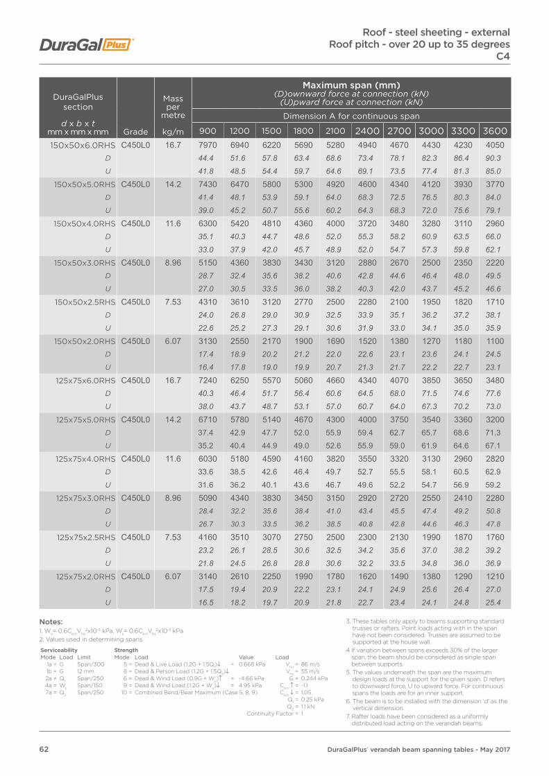
62 DuraGalPlus® verandah beam spanning tables - May 2017
Roof - steel sheeting - externalRoof pitch - over 20 up to 35 degrees
C4
DuraGalPlus section
d x b x tmm x mm x mm Grade
Mass per
metre
kg/m
Maximum span (mm)(D)ownward force at connection (kN)
(U)pward force at connection (kN)
Dimension A for continuous span
900 1200 1500 1800 2100 2400 2700 3000 3300 3600
150x50x6.0RHS C450L0 16.7 7970 6940 6220 5690 5280 4940 4670 4430 4230 4050D 44.4 51.6 57.8 63.4 68.6 73.4 78.1 82.3 86.4 90.3U 41.8 48.5 54.4 59.7 64.6 69.1 73.5 77.4 81.3 85.0
150x50x5.0RHS C450L0 14.2 7430 6470 5800 5300 4920 4600 4340 4120 3930 3770D 41.4 48.1 53.9 59.1 64.0 68.3 72.5 76.5 80.3 84.0U 39.0 45.2 50.7 55.6 60.2 64.3 68.3 72.0 75.6 79.1
150x50x4.0RHS C450L0 11.6 6300 5420 4810 4360 4000 3720 3480 3280 3110 2960D 35.1 40.3 44.7 48.6 52.0 55.3 58.2 60.9 63.5 66.0U 33.0 37.9 42.0 45.7 48.9 52.0 54.7 57.3 59.8 62.1
150x50x3.0RHS C450L0 8.96 5150 4360 3830 3430 3120 2880 2670 2500 2350 2220D 28.7 32.4 35.6 38.2 40.6 42.8 44.6 46.4 48.0 49.5U 27.0 30.5 33.5 36.0 38.2 40.3 42.0 43.7 45.2 46.6
150x50x2.5RHS C450L0 7.53 4310 3610 3120 2770 2500 2280 2100 1950 1820 1710D 24.0 26.8 29.0 30.9 32.5 33.9 35.1 36.2 37.2 38.1U 22.6 25.2 27.3 29.1 30.6 31.9 33.0 34.1 35.0 35.9
150x50x2.0RHS C450L0 6.07 3130 2550 2170 1900 1690 1520 1380 1270 1180 1100D 17.4 18.9 20.2 21.2 22.0 22.6 23.1 23.6 24.1 24.5U 16.4 17.8 19.0 19.9 20.7 21.3 21.7 22.2 22.7 23.1
125x75x6.0RHS C450L0 16.7 7240 6250 5570 5060 4660 4340 4070 3850 3650 3480D 40.3 46.4 51.7 56.4 60.6 64.5 68.0 71.5 74.6 77.6U 38.0 43.7 48.7 53.1 57.0 60.7 64.0 67.3 70.2 73.0
125x75x5.0RHS C450L0 14.2 6710 5780 5140 4670 4300 4000 3750 3540 3360 3200D 37.4 42.9 47.7 52.0 55.9 59.4 62.7 65.7 68.6 71.3U 35.2 40.4 44.9 49.0 52.6 55.9 59.0 61.9 64.6 67.1
125x75x4.0RHS C450L0 11.6 6030 5180 4590 4160 3820 3550 3320 3130 2960 2820D 33.6 38.5 42.6 46.4 49.7 52.7 55.5 58.1 60.5 62.9U 31.6 36.2 40.1 43.6 46.7 49.6 52.2 54.7 56.9 59.2
125x75x3.0RHS C450L0 8.96 5090 4340 3830 3450 3150 2920 2720 2550 2410 2280D 28.4 32.2 35.6 38.4 41.0 43.4 45.5 47.4 49.2 50.8
U 26.7 30.3 33.5 36.2 38.5 40.8 42.8 44.6 46.3 47.8
125x75x2.5RHS C450L0 7.53 4160 3510 3070 2750 2500 2300 2130 1990 1870 1760D 23.2 26.1 28.5 30.6 32.5 34.2 35.6 37.0 38.2 39.2U 21.8 24.5 26.8 28.8 30.6 32.2 33.5 34.8 36.0 36.9
125x75x2.0RHS C450L0 6.07 3140 2610 2250 1990 1780 1620 1490 1380 1290 1210D 17.5 19.4 20.9 22.2 23.1 24.1 24.9 25.6 26.4 27.0U 16.5 18.2 19.7 20.9 21.8 22.7 23.4 24.1 24.8 25.4
Notes:1. Wu= 0.6Cp,nVhu
2x10⁻³ kPa, Ws= 0.6Cp,nVhs2x10-3 kPa
2. Values used in determining spans.
Serviceability StrengthMode Load Limit Mode Load Value Load
1a = G Span/300 5 = Dead & Live Load (1.2G + 1.5Q1)↓ = 0.668 kPa Vhu = 86 m/s1b = G 12 mm 8 = Dead & Person Load (1.2G + 1.5Q2)↓ Vhs = 55 m/s2a = Q1 Span/250 6 = Dead & Wind Load (0.9G + Wu)↑ = -4.66 kPa G = 0.244 kPa4a = Ws Span/150 9 = Dead & Wind Load (1.2G + Wu)↓ = 4.95 kPa Cp,n ↑ = -1.17a = Q2 Span/250 10 = Combined Bend/Bear Maximum (Case 5, 8, 9) Cp,n ↓ = 1.05
Q1 = 0.25 kPaQ2 = 1.1 kN
Continuity Factor = 1
3. These tables only apply to beams supporting standard trusses or rafters. Point loads acting with in the span have not been considered. Trusses are assumed to be supported at the house wall.
4 If variation between spans exceeds 30% of the larger span, the beam should be considered as single span between supports.
5. The values underneath the span are the maximum design loads at the support for the given span. D refers to downward force, U to upward force. For continuous spans the loads are for an inner support.
6. The beam is to be installed with the dimension ‘d’ as the vertical dimension.
7. Rafter loads have been considered as a uniformly distributed load acting on the verandah beams.

63DuraGalPlus® verandah beam spanning tables - May 2017
Roof - steel sheeting - externalRoof pitch - over 20 up to 35 degreesC4
DuraGalPlus section
d x b x tmm x mm x mm Grade
Mass per
metre
kg/m
Maximum span (mm)(D)ownward force at connection (kN)
(U)pward force at connection (kN)
Dimension A for continuous span
900 1200 1500 1800 2100 2400 2700 3000 3300 3600100x50x5.0RHS C450L0 10.3 5300 4610 4130 3780 3500 3280 3090 2930 2800 2680
D 29.5 34.2 38.4 42.1 45.5 48.7 51.7 54.4 57.2 59.7U 27.8 32.2 36.1 39.6 42.8 45.9 48.6 51.2 53.8 56.2
100x50x4.0RHS C450L0 8.49 4870 4230 3790 3470 3210 3010 2830 2690 2570 2460D 27.1 31.4 35.2 38.7 41.7 44.7 47.3 50.0 52.5 54.8U 25.5 29.6 33.1 36.4 39.3 42.1 44.5 47.0 49.4 51.6
100x50x3.5RHS C450L0 7.53 4620 4010 3590 3280 3040 2850 2680 2550 2430 2330D 25.7 29.8 33.3 36.6 39.5 42.3 44.8 47.4 49.6 51.9U 24.2 28.0 31.4 34.4 37.2 39.9 42.2 44.6 46.7 48.9
100x50x3.0RHS C450L0 6.6 4070 3500 3100 2810 2580 2400 2250 2120 2010 1910D 22.7 26.0 28.8 31.3 33.5 35.7 37.6 39.4 41.1 42.6U 21.3 24.5 27.1 29.5 31.6 33.6 35.4 37.1 38.6 40.1
100x50x2.5RHS C450L0 5.56 3620 3090 2730 2460 2250 2080 1940 1830 1720 1640D 20.2 23.0 25.4 27.4 29.3 30.9 32.4 34.0 35.1 36.6U 19.0 21.6 23.9 25.8 27.5 29.1 30.5 32.0 33.1 34.4
100x50x2.0RHS C450L0 4.50 3000 2530 2210 1970 1790 1640 1520 1420 1330 1260D 16.7 18.8 20.5 22.0 23.3 24.4 25.4 26.4 27.2 28.1U 15.7 17.7 19.3 20.7 21.9 22.9 23.9 24.8 25.6 26.4
100x50x1.6RHS C450L0 3.64 2220 1840 1580 1400 1260 1140 1050 970 900 850D 12.4 13.7 14.7 15.6 16.4 16.9 17.6 18.0 18.4 18.9U 11.6 12.9 13.8 14.7 15.4 15.9 16.5 17.0 17.3 17.8
100x100x3.0SHS C450L0 8.96 3810 3190 2760 2450 2210 2020 1860 1720 1610 1510D 21.2 23.7 25.6 27.3 28.7 30.0 31.1 31.9 32.9 33.7U 20.0 22.3 24.1 25.7 27.0 28.2 29.3 30.1 31.0 31.7
100x100x2.5SHS C450L0 7.53 3440 2890 2510 2240 2020 1850 1710 1590 1490 1400D 19.2 21.5 23.3 25.0 26.3 27.5 28.6 29.5 30.4 31.2U 18.0 20.2 21.9 23.5 24.7 25.9 26.9 27.8 28.7 29.4
100x100x2.0SHS C450L0 6.07 3030 2550 2230 1990 1810 1660 1540 1430 1340 1270D 16.9 18.9 20.7 22.2 23.5 24.7 25.7 26.6 27.4 28.3U 15.9 17.8 19.5 20.9 22.1 23.2 24.2 25.0 25.8 26.6
90x90x2.0SHS C450L0 5.45 2840 2400 2100 1870 1700 1560 1450 1360 1270 1200D 15.8 17.8 19.5 20.8 22.1 23.2 24.2 25.3 25.9 26.7U 14.9 16.8 18.4 19.6 20.8 21.8 22.8 23.8 24.4 25.2
Notes:1. Wu= 0.6Cp,nVhu
2x10⁻³ kPa, Ws= 0.6Cp,nVhs2x10-3 kPa
2. Values used in determining spans.
Serviceability StrengthMode Load Limit Mode Load Value Load
1a = G Span/300 5 = Dead & Live Load (1.2G + 1.5Q1)↓ = 0.668 kPa Vhu = 86 m/s1b = G 12 mm 8 = Dead & Person Load (1.2G + 1.5Q2)↓ Vhs = 55 m/s2a = Q1 Span/250 6 = Dead & Wind Load (0.9G + Wu)↑ = -4.66 kPa G = 0.244 kPa4a = Ws Span/150 9 = Dead & Wind Load (1.2G + Wu)↓ = 4.95 kPa Cp,n ↑ = -1.17a = Q2 Span/250 10 = Combined Bend/Bear Maximum (Case 5, 8, 9) Cp,n ↓ = 1.05
Q1 = 0.25 kPaQ2 = 1.1 kN
Continuity Factor = 1
3. These tables only apply to beams supporting standard trusses or rafters. Point loads acting with in the span have not been considered. Trusses are assumed to be supported at the house wall.
4 If variation between spans exceeds 30% of the larger span, the beam should be considered as single span between supports.
5. The values underneath the span are the maximum design loads at the support for the given span. D refers to downward force, U to upward force. For continuous spans the loads are for an inner support.
6. The beam is to be installed with the dimension ‘d’ as the vertical dimension.
7. Rafter loads have been considered as a uniformly distributed load acting on the verandah beams.
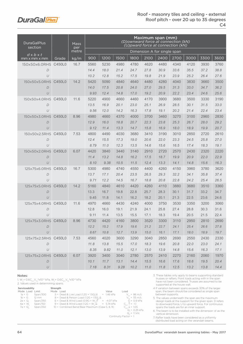
64 DuraGalPlus® verandah beam spanning tables - May 2017
DuraGalPlus section
d x b x tmm x mm x mm Grade
Mass per
metre
kg/m
Maximum span (mm)(D)ownward force at connection (kN)
(U)pward force at connection (kN)
Dimension A for single span
900 1200 1500 1800 2100 2400 2700 3000 3300 3600
150x50x6.0RHS C450L0 16.7 5560 5230 4980 4780 4620 4480 4340 4120 3930 3760D 14.4 18.0 21.4 24.7 27.8 30.9 33.6 35.5 37.2 38.8U 10.2 12.8 15.2 17.5 19.8 21.9 23.9 25.2 26.4 27.6
150x50x5.0RHS C450L0 14.2 5420 5090 4840 4640 4480 4280 4040 3830 3660 3500D 14.0 17.5 20.8 24.0 27.0 29.5 31.3 33.0 34.7 36.2U 9.93 12.4 14.8 17.0 19.2 20.9 22.2 23.4 24.6 25.6
150x50x4.0RHS C450L0 11.6 5220 4900 4660 4460 4170 3900 3680 3500 3330 3190D 13.5 16.9 20.1 23.0 25.1 26.9 28.5 30.1 31.5 33.0U 9.56 12.0 14.2 16.3 17.8 19.1 20.2 21.4 22.4 23.4
150x50x3.0RHS C450L0 8.96 4980 4660 4370 4000 3700 3460 3270 3100 2960 2830D 12.9 16.0 18.8 20.7 22.3 23.8 25.3 26.7 28.0 29.2U 9.12 11.4 13.3 14.7 15.8 16.9 18.0 18.9 19.9 20.7
150x50x2.5RHS C450L0 7.53 4800 4490 4030 3680 3410 3190 3010 2850 2720 2610D 12.4 15.5 17.3 19.0 20.6 22.0 23.3 24.5 25.8 27.0U 8.79 11.0 12.3 13.5 14.6 15.6 16.5 17.4 18.3 19.1
150x50x2.0RHS C450L0 6.07 4420 3840 3440 3140 2910 2720 2570 2430 2320 2220D 11.4 13.2 14.8 16.2 17.5 18.7 19.9 20.9 22.0 22.9U 8.10 9.38 10.5 11.5 12.4 13.3 14.1 14.8 15.6 16.3
125x75x6.0RHS C450L0 16.7 5300 4980 4740 4550 4400 4260 4150 3960 3780 3620D 13.7 17.1 20.4 23.5 26.5 29.3 32.2 34.1 35.8 37.4U 9.71 12.2 14.5 16.7 18.8 20.8 22.8 24.2 25.4 26.5
125x75x5.0RHS C450L0 14.2 5160 4840 4610 4420 4260 4110 3880 3680 3510 3360D 13.3 16.7 19.8 22.8 25.7 28.3 30.1 31.7 33.2 34.7U 9.45 11.8 14.1 16.2 18.2 20.1 21.3 22.5 23.6 24.6
125x75x4.0RHS C450L0 11.6 4970 4660 4430 4240 4000 3750 3530 3350 3200 3060D 12.8 16.0 19.1 21.9 24.1 25.8 27.4 28.8 30.3 31.6U 9.11 11.4 13.5 15.5 17.1 18.3 19.4 20.5 21.5 22.4
125x75x3.0RHS C450L0 8.96 4730 4420 4160 3800 3520 3300 3110 2950 2810 2690D 12.2 15.2 17.9 19.6 21.2 22.7 24.1 25.4 26.6 27.8
U 8.67 10.8 12.7 13.9 15.0 16.1 17.1 18.0 18.9 19.7
125x75x2.5RHS C450L0 7.53 4560 4020 3600 3290 3040 2850 2690 2550 2430 2330D 11.8 13.8 15.5 17.0 18.3 19.6 20.8 22.0 23.0 24.1U 8.35 9.82 11.0 12.1 13.0 13.9 14.8 15.6 16.3 17.1
125x75x2.0RHS C450L0 6.07 3920 3400 3040 2780 2570 2410 2270 2160 2060 1970D 10.1 11.7 13.1 14.4 15.5 16.6 17.6 18.6 19.5 20.4U 7.18 8.31 9.28 10.2 11.0 11.8 12.5 13.2 13.8 14.4
Roof - masonry tiles and ceiling - externalRoof pitch - over 20 up to 35 degrees
C4
Notes:1. Wu= 0.6Cp,nVhu
2x10⁻³ kPa, Ws= 0.6Cp,nVhs2x10-3 kPa
2. Values used in determining spans.
Serviceability StrengthMode Load Limit Mode Load Value Load
1a = G Span/300 5 = Dead & Live Load (1.2G + 1.5Q1)↓ = 1.46 kPa Vhu = 86 m/s1b = G 12 mm 8 = Dead & Person Load (1.2G + 1.5Q2)↓ Vhs = 55 m/s2a = Q1 Span/250 6 = Dead & Wind Load (0.9G + Wu)↑ = -4.07 kPa G = 0.9 kPa4a = Ws Span/150 9 = Dead & Wind Load (1.2G + Wu)↓ = 5.74 kPa Cp,n ↑ = -1.17a = Q2 Span/250 10 = Combined Bend/Bear Maximum (Case 5, 8, 9) Cp,n ↓ = 1.05
Q1 = 0.25 kPaQ2 = 1.1 kN
Continuity Factor = 1
3. These tables only apply to beams supporting standard trusses or rafters. Point loads acting with in the span have not been considered. Trusses are assumed to be supported at the house wall.
4 If variation between spans exceeds 30% of the larger span, the beam should be considered as single span between supports.
5. The values underneath the span are the maximum design loads at the support for the given span. D refers to downward force, U to upward force. For continuous spans the loads are for an inner support.
6. The beam is to be installed with the dimension ‘d’ as the vertical dimension.
7. Rafter loads have been considered as a uniformly distributed load acting on the verandah beams.

65DuraGalPlus® verandah beam spanning tables - May 2017
DuraGalPlus section
d x b x tmm x mm x mm Grade
Mass per
metre
kg/m
Maximum span (mm)(D)ownward force at connection (kN)
(U)pward force at connection (kN)
Dimension A for single span
900 1200 1500 1800 2100 2400 2700 3000 3300 3600
100x50x5.0RHS C450L0 10.3 4190 3930 3730 3510 3250 3040 2870 2730 2600 2490D 10.8 13.5 16.1 18.1 19.6 20.9 22.2 23.5 24.6 25.7U 7.68 9.60 11.4 12.9 13.9 14.9 15.8 16.7 17.5 18.2
100x50x4.0RHS C450L0 8.49 4050 3790 3530 3220 2980 2790 2630 2500 2380 2280D 10.5 13.1 15.2 16.6 18.0 19.2 20.4 21.5 22.5 23.6U 7.42 9.26 10.8 11.8 12.7 13.6 14.5 15.3 16.0 16.7
100x50x3.5RHS C450L0 7.53 3960 3700 3340 3050 2830 2650 2490 2370 2260 2160D 10.2 12.7 14.4 15.8 17.1 18.3 19.3 20.4 21.4 22.3U 7.26 9.04 10.2 11.2 12.1 12.9 13.7 14.5 15.2 15.8
100x50x3.0RHS C450L0 6.6 3870 3520 3150 2880 2670 2500 2350 2230 2130 2040D 10.00 12.1 13.6 14.9 16.1 17.2 18.2 19.2 20.2 21.1U 7.09 8.60 9.62 10.6 11.4 12.2 12.9 13.6 14.3 15.0
100x50x2.5RHS C450L0 5.56 3730 3250 2910 2660 2460 2300 2170 2060 1970 1880D 9.63 11.2 12.5 13.7 14.8 15.8 16.8 17.7 18.7 19.4U 6.83 7.94 8.89 9.75 10.5 11.2 11.9 12.6 13.2 13.8
100x50x2.0RHS C450L0 4.50 3360 2920 2610 2380 2210 2070 1950 1850 1760 1690D 8.68 10.1 11.2 12.3 13.3 14.3 15.1 15.9 16.7 17.5U 6.16 7.13 7.97 8.72 9.45 10.1 10.7 11.3 11.8 12.4
100x50x1.6RHS C450L0 3.64 2790 2410 2160 1970 1830 1710 1610 1530 1460 1400D 7.21 8.30 9.30 10.2 11.0 11.8 12.5 13.2 13.8 14.5U 5.11 5.89 6.60 7.22 7.82 8.35 8.85 9.34 9.81 10.3
100x100x3.0SHS C450L0 8.96 4370 3990 3570 3270 3030 2830 2670 2530 2420 2320D 11.3 13.7 15.4 16.9 18.3 19.5 20.7 21.8 22.9 24.0U 8.01 9.75 10.9 12.0 13.0 13.8 14.7 15.5 16.3 17.0
100x100x2.5SHS C450L0 7.53 4010 3480 3120 2850 2640 2470 2330 2210 2110 2020D 10.4 12.0 13.4 14.7 15.9 17.0 18.1 19.0 20.0 20.9U 7.35 8.50 9.53 10.4 11.3 12.1 12.8 13.5 14.2 14.8
100x100x2.0SHS C450L0 6.07 3410 2960 2650 2420 2240 2100 1980 1880 1790 1720D 8.81 10.2 11.4 12.5 13.5 14.5 15.3 16.2 17.0 17.8U 6.25 7.23 8.09 8.87 9.58 10.3 10.9 11.5 12.0 12.6
90x90x2.0SHS C450L0 5.45 3150 2730 2440 2230 2070 1940 1830 1730 1650 1580D 8.14 9.40 10.5 11.5 12.5 13.4 14.2 14.9 15.6 16.3U 5.77 6.67 7.45 8.17 8.85 9.48 10.1 10.6 11.1 11.6
Roof - masonry tiles and ceiling - externalRoof pitch - over 20 up to 35 degreesC4
Notes:1. Wu= 0.6Cp,nVhu
2x10⁻³ kPa, Ws= 0.6Cp,nVhs2x10-3 kPa
2. Values used in determining spans.
Serviceability StrengthMode Load Limit Mode Load Value Load
1a = G Span/300 5 = Dead & Live Load (1.2G + 1.5Q1)↓ = 1.46 kPa Vhu = 86 m/s1b = G 12 mm 8 = Dead & Person Load (1.2G + 1.5Q2)↓ Vhs = 55 m/s2a = Q1 Span/250 6 = Dead & Wind Load (0.9G + Wu)↑ = -4.07 kPa G = 0.9 kPa4a = Ws Span/150 9 = Dead & Wind Load (1.2G + Wu)↓ = 5.74 kPa Cp,n ↑ = -1.17a = Q2 Span/250 10 = Combined Bend/Bear Maximum (Case 5, 8, 9) Cp,n ↓ = 1.05
Q1 = 0.25 kPaQ2 = 1.1 kN
Continuity Factor = 1
3. These tables only apply to beams supporting standard trusses or rafters. Point loads acting with in the span have not been considered. Trusses are assumed to be supported at the house wall.
4 If variation between spans exceeds 30% of the larger span, the beam should be considered as single span between supports.
5. The values underneath the span are the maximum design loads at the support for the given span. D refers to downward force, U to upward force. For continuous spans the loads are for an inner support.
6. The beam is to be installed with the dimension ‘d’ as the vertical dimension.
7. Rafter loads have been considered as a uniformly distributed load acting on the verandah beams.

66 DuraGalPlus® verandah beam spanning tables - May 2017
Roof - masonry tiles and ceiling - externalRoof pitch - over 20 up to 35 degrees
C4
DuraGalPlus section
d x b x tmm x mm x mm Grade
Mass per
metre
kg/m
Maximum span (mm)(D)ownward force at connection (kN)
(U)pward force at connection (kN)
Dimension A for continuous span
900 1200 1500 1800 2100 2400 2700 3000 3300 3600
150x50x6.0RHS C450L0 16.7 6930 6460 5790 5300 4910 4600 4340 4120 3930 3760D 44.7 55.6 62.3 68.4 74.0 79.2 84.1 88.7 93.0 97.1U 31.7 39.5 44.2 48.6 52.5 56.2 59.6 62.9 66.0 68.9
150x50x5.0RHS C450L0 14.2 6750 6020 5400 4930 4570 4280 4040 3830 3660 3500D 43.6 51.8 58.1 63.7 68.9 73.7 78.3 82.4 86.7 90.4U 30.9 36.8 41.2 45.2 48.8 52.3 55.5 58.5 61.5 64.1
150x50x4.0RHS C450L0 11.6 5830 5010 4440 4020 3690 3430 3210 3020 2860 2720D 37.6 43.1 47.8 51.9 55.6 59.1 62.2 65.0 67.7 70.3U 26.7 30.6 33.9 36.8 39.4 41.9 44.1 46.1 48.0 49.8
150x50x3.0RHS C450L0 8.96 4730 4000 3500 3140 2850 2620 2430 2270 2140 2020D 30.5 34.4 37.7 40.5 42.9 45.1 47.1 48.9 50.7 52.2U 21.7 24.4 26.7 28.8 30.5 32.0 33.4 34.7 35.9 37.0
150x50x2.5RHS C450L0 7.53 3940 3280 2840 2510 2260 2060 1890 1760 1640 1540D 25.4 28.2 30.6 32.4 34.0 35.5 36.6 37.9 38.8 39.8U 18.0 20.0 21.7 23.0 24.2 25.2 26.0 26.9 27.5 28.2
150x50x2.0RHS C450L0 6.07 2820 2300 1950 1690 1500 1350 1230 1130 1040 970D 18.2 19.8 21.0 21.8 22.6 23.2 23.8 24.3 24.6 25.1U 12.9 14.0 14.9 15.5 16.0 16.5 16.9 17.3 17.5 17.8
125x75x6.0RHS C450L0 16.7 6600 5790 5150 4680 4310 4010 3760 3550 3370 3210D 42.6 49.8 55.4 60.4 64.9 69.0 72.8 76.4 79.8 82.9U 30.2 35.4 39.3 42.9 46.1 49.0 51.7 54.2 56.6 58.8
125x75x5.0RHS C450L0 14.2 6220 5350 4750 4310 3970 3690 3460 3260 3090 2940D 40.2 46.1 51.1 55.7 59.8 63.5 67.0 70.2 73.2 75.9U 28.5 32.7 36.3 39.5 42.4 45.1 47.5 49.8 51.9 53.9
125x75x4.0RHS C450L0 11.6 5580 4780 4240 3830 3520 3270 3050 2880 2720 2590D 36.0 41.2 45.6 49.5 53.0 56.3 59.1 62.0 64.4 66.9U 25.6 29.2 32.4 35.1 37.6 39.9 41.9 44.0 45.7 47.5
125x75x3.0RHS C450L0 8.96 4700 4000 3520 3170 2890 2670 2490 2330 2200 2080D 30.3 34.4 37.9 40.9 43.5 46.0 48.2 50.1 52.1 53.7
U 21.5 24.4 26.9 29.0 30.9 32.6 34.2 35.6 36.9 38.1
125x75x2.5RHS C450L0 7.53 3820 3220 2810 2510 2280 2090 1940 1810 1690 1600D 24.7 27.7 30.2 32.4 34.4 36.0 37.6 39.0 40.0 41.3U 17.5 19.7 21.5 23.0 24.4 25.5 26.7 27.6 28.4 29.3
125x75x2.0RHS C450L0 6.07 2860 2370 2030 1790 1610 1460 1340 1240 1150 1080D 18.5 20.4 21.8 23.1 24.3 25.1 26.0 26.7 27.2 27.9U 13.1 14.5 15.5 16.4 17.2 17.8 18.4 18.9 19.3 19.8
Notes:1. Wu= 0.6Cp,nVhu
2x10⁻³ kPa, Ws= 0.6Cp,nVhs2x10-3 kPa
2. Values used in determining spans.
Serviceability StrengthMode Load Limit Mode Load Value Load
1a = G Span/300 5 = Dead & Live Load (1.2G + 1.5Q1)↓ = 1.46 kPa Vhu = 86 m/s1b = G 12 mm 8 = Dead & Person Load (1.2G + 1.5Q2)↓ Vhs = 55 m/s2a = Q1 Span/250 6 = Dead & Wind Load (0.9G + Wu)↑ = -4.07 kPa G = 0.9 kPa4a = Ws Span/150 9 = Dead & Wind Load (1.2G + Wu)↓ = 5.74 kPa Cp,n ↑ = -1.17a = Q2 Span/250 10 = Combined Bend/Bear Maximum (Case 5, 8, 9) Cp,n ↓ = 1.05
Q1 = 0.25 kPaQ2 = 1.1 kN
Continuity Factor = 1
3. These tables only apply to beams supporting standard trusses or rafters. Point loads acting with in the span have not been considered. Trusses are assumed to be supported at the house wall.
4 If variation between spans exceeds 30% of the larger span, the beam should be considered as single span between supports.
5. The values underneath the span are the maximum design loads at the support for the given span. D refers to downward force, U to upward force. For continuous spans the loads are for an inner support.
6. The beam is to be installed with the dimension ‘d’ as the vertical dimension.
7. Rafter loads have been considered as a uniformly distributed load acting on the verandah beams.
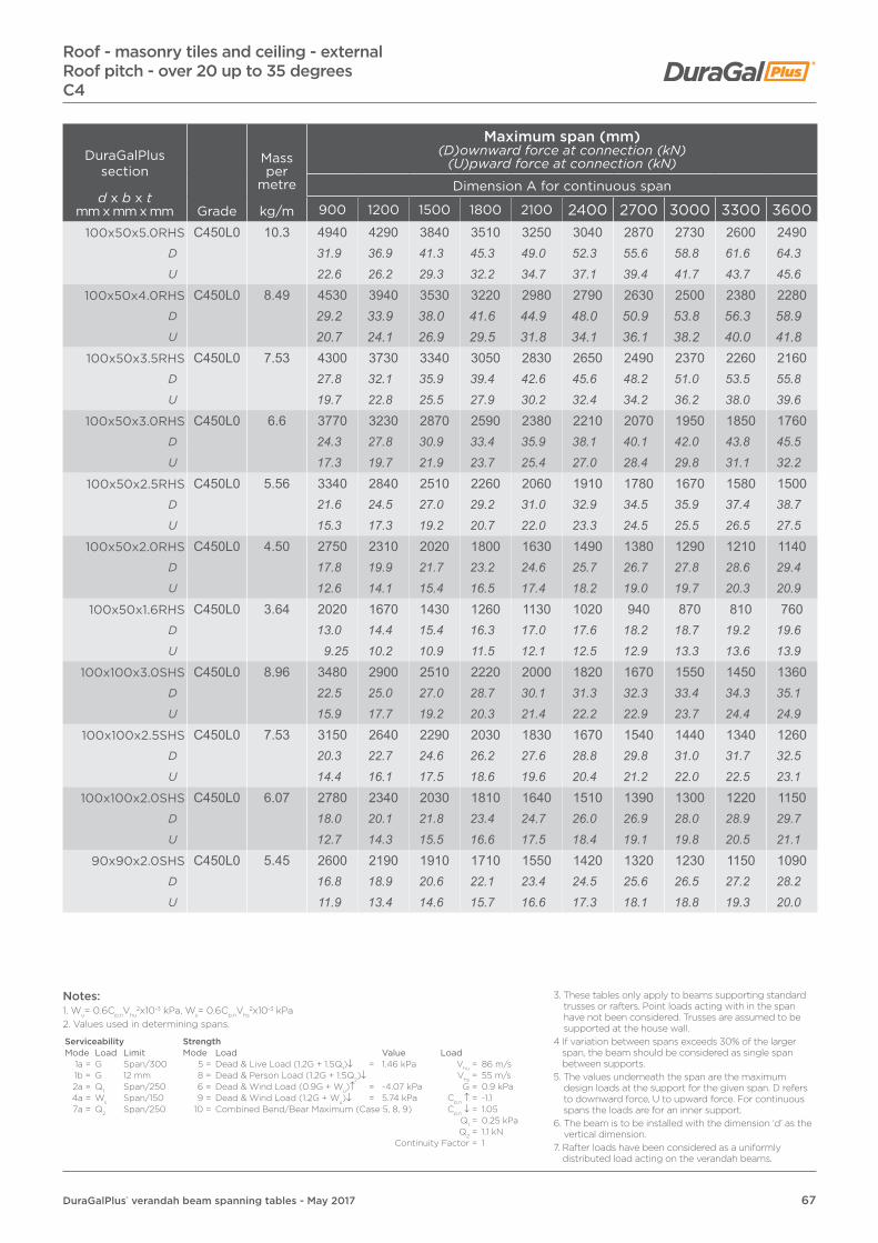
67DuraGalPlus® verandah beam spanning tables - May 2017
Roof - masonry tiles and ceiling - externalRoof pitch - over 20 up to 35 degreesC4
DuraGalPlus section
d x b x tmm x mm x mm Grade
Mass per
metre
kg/m
Maximum span (mm)(D)ownward force at connection (kN)
(U)pward force at connection (kN)
Dimension A for continuous span
900 1200 1500 1800 2100 2400 2700 3000 3300 3600100x50x5.0RHS C450L0 10.3 4940 4290 3840 3510 3250 3040 2870 2730 2600 2490
D 31.9 36.9 41.3 45.3 49.0 52.3 55.6 58.8 61.6 64.3U 22.6 26.2 29.3 32.2 34.7 37.1 39.4 41.7 43.7 45.6
100x50x4.0RHS C450L0 8.49 4530 3940 3530 3220 2980 2790 2630 2500 2380 2280D 29.2 33.9 38.0 41.6 44.9 48.0 50.9 53.8 56.3 58.9U 20.7 24.1 26.9 29.5 31.8 34.1 36.1 38.2 40.0 41.8
100x50x3.5RHS C450L0 7.53 4300 3730 3340 3050 2830 2650 2490 2370 2260 2160D 27.8 32.1 35.9 39.4 42.6 45.6 48.2 51.0 53.5 55.8U 19.7 22.8 25.5 27.9 30.2 32.4 34.2 36.2 38.0 39.6
100x50x3.0RHS C450L0 6.6 3770 3230 2870 2590 2380 2210 2070 1950 1850 1760D 24.3 27.8 30.9 33.4 35.9 38.1 40.1 42.0 43.8 45.5U 17.3 19.7 21.9 23.7 25.4 27.0 28.4 29.8 31.1 32.2
100x50x2.5RHS C450L0 5.56 3340 2840 2510 2260 2060 1910 1780 1670 1580 1500D 21.6 24.5 27.0 29.2 31.0 32.9 34.5 35.9 37.4 38.7U 15.3 17.3 19.2 20.7 22.0 23.3 24.5 25.5 26.5 27.5
100x50x2.0RHS C450L0 4.50 2750 2310 2020 1800 1630 1490 1380 1290 1210 1140D 17.8 19.9 21.7 23.2 24.6 25.7 26.7 27.8 28.6 29.4U 12.6 14.1 15.4 16.5 17.4 18.2 19.0 19.7 20.3 20.9
100x50x1.6RHS C450L0 3.64 2020 1670 1430 1260 1130 1020 940 870 810 760D 13.0 14.4 15.4 16.3 17.0 17.6 18.2 18.7 19.2 19.6U 9.25 10.2 10.9 11.5 12.1 12.5 12.9 13.3 13.6 13.9
100x100x3.0SHS C450L0 8.96 3480 2900 2510 2220 2000 1820 1670 1550 1450 1360D 22.5 25.0 27.0 28.7 30.1 31.3 32.3 33.4 34.3 35.1U 15.9 17.7 19.2 20.3 21.4 22.2 22.9 23.7 24.4 24.9
100x100x2.5SHS C450L0 7.53 3150 2640 2290 2030 1830 1670 1540 1440 1340 1260D 20.3 22.7 24.6 26.2 27.6 28.8 29.8 31.0 31.7 32.5U 14.4 16.1 17.5 18.6 19.6 20.4 21.2 22.0 22.5 23.1
100x100x2.0SHS C450L0 6.07 2780 2340 2030 1810 1640 1510 1390 1300 1220 1150D 18.0 20.1 21.8 23.4 24.7 26.0 26.9 28.0 28.9 29.7U 12.7 14.3 15.5 16.6 17.5 18.4 19.1 19.8 20.5 21.1
90x90x2.0SHS C450L0 5.45 2600 2190 1910 1710 1550 1420 1320 1230 1150 1090D 16.8 18.9 20.6 22.1 23.4 24.5 25.6 26.5 27.2 28.2U 11.9 13.4 14.6 15.7 16.6 17.3 18.1 18.8 19.3 20.0
Notes:1. Wu= 0.6Cp,nVhu
2x10⁻³ kPa, Ws= 0.6Cp,nVhs2x10-3 kPa
2. Values used in determining spans.
Serviceability StrengthMode Load Limit Mode Load Value Load
1a = G Span/300 5 = Dead & Live Load (1.2G + 1.5Q1)↓ = 1.46 kPa Vhu = 86 m/s1b = G 12 mm 8 = Dead & Person Load (1.2G + 1.5Q2)↓ Vhs = 55 m/s2a = Q1 Span/250 6 = Dead & Wind Load (0.9G + Wu)↑ = -4.07 kPa G = 0.9 kPa4a = Ws Span/150 9 = Dead & Wind Load (1.2G + Wu)↓ = 5.74 kPa Cp,n ↑ = -1.17a = Q2 Span/250 10 = Combined Bend/Bear Maximum (Case 5, 8, 9) Cp,n ↓ = 1.05
Q1 = 0.25 kPaQ2 = 1.1 kN
Continuity Factor = 1
3. These tables only apply to beams supporting standard trusses or rafters. Point loads acting with in the span have not been considered. Trusses are assumed to be supported at the house wall.
4 If variation between spans exceeds 30% of the larger span, the beam should be considered as single span between supports.
5. The values underneath the span are the maximum design loads at the support for the given span. D refers to downward force, U to upward force. For continuous spans the loads are for an inner support.
6. The beam is to be installed with the dimension ‘d’ as the vertical dimension.
7. Rafter loads have been considered as a uniformly distributed load acting on the verandah beams.
This publication has been prepared as a guide only to assist anyone that may specify or use the products described in this publication. Accordingly, while Austube Mills has endeavoured to ensure that all information provided in this publication is accurate and up-to-date, the following must be noted: this publication does not take into account any individual circumstances and is therefore not a substitute for informed or professional individual advice; the specifications and technical data relating to the products described in this publication are approximate and subject to change without notice, and users should check the currency of the information before relying upon it; and unless required by law, Austube Mills does not accept any responsibility for any loss, damage or consequence resulting from the contents of this publication or from any omission of information in this publication. © Copyright Austube Mills Pty Ltd. DuraGal, DuraGalPlus, the Austube Mills logo and the Australian Map of tubes are registered trade marks of Austube Mills Pty Ltd. Issued May 2017. TS3047.
Address Industrial Drive, Mayfield NSW 2304 | PO Box 156, Newcastle NSW 2300, AustraliaPhone 1800 281 424 | Fax +61 7 3909 6660
Web www.austubemills.com