Durability of Adhesive Joints -cyclic loading -viscoplasticity
34
Durability of Adhesive Joints -cyclic loading -viscoplasticity 2019 JAMS Annual Meeting 5/22/19
Transcript of Durability of Adhesive Joints -cyclic loading -viscoplasticity

Durability of Adhesive Joints
-cyclic loading
-viscoplasticity
2019 JAMS Annual Meeting
5/22/19

• Principal Investigators & Researchers– Lloyd Smith– Yi Chen, Michael Krause
• FAA Technical Monitor– Ahmet Oztekin
• Other FAA Personnel Involved– Larry Ilcewicz
• Industry Participation– The Boeing Company: Will Grace, Kay Blohowiak,
Ashley Tracey

• Motivation and Key Issues – Adhesive bonding is a key path towards reduced weight in aerospace structures.
– Certification requirements for bonded structures are not well defined.
• Objective– Explore cyclic response of adhesive joints.
– Develop predictive models describing adhesive time and plastic response.
• Approach– Experiments designed to clarify constitutive relations.
– Develop FEA Models of adhesive bonds.
– Compare models with experiments that are unlike constitutive tests.

Review: Bulk Coupon, EA9696
20% UTS
50% UTS
80% UTS
Ratcheting triangle wave

Viscoelastic Response in Shear
Bulk Tension End Notch Flexure
(unnotched)
Wide Area Lap Shear
Creep
Ratchet

Why Scarf Joint?
-6,000
-5,000
-4,000
-3,000
-2,000
-1,000
0
1,000
0 0.2 0.4 0.6 0.8 1
Str
ess
(psi
)Non-Dimensional Length
WALS vs Scarf - Shear Stress
WALS Scarf Joint
-5,000
0
5,000
10,000
15,000
0 0.2 0.4 0.6 0.8 1
Str
ess
(psi
)
Non-Dimensional Length
WALS vs Scarf - Peel StressWALS Scarf Joint
FEA Results :
• Scarf has no load eccentricity
• Scarf has a uniform distribution of shear
stress
• Scarf has minimal peel stress
-3000
-2000
-1000
0
1000
2000
3000
0 10 20 30 40 50 60 70
Avera
ge s
tress
(psi
)
Scarf angle (deg)
Peel Shear
Why 10 degree
6

Measuring Cyclic strain
Thin bond prevents traditional direct methods
Extensometer tends to drift with cyclic loading
DIC is computationally expensive
Shear modulus gage not available
Considered a stacked rosette
Maximum strain not sensitive to gage orientation

Scarf Coupon
EA9696

Strain Modifications
ε1
ε2
ε3
• Divided each strain by the percentage of the gage covering the adhesive
• Strain Gauge Area: 0.064in x 0.05in
• Adhesive Thickness: 0.008in
ε’1= ε1a/t ε’2= ε2a cos(45o)/t ε’3= ε3b/t
γxy = 2ε’2-ε’1-ε’3
b
a
t
45o
yx

Monotonic Testing Results Ultimate Shear Strength (USS): 6 ksi
Adhesive Shear Modulus: 88.5 ksi
Verified through digital imaging correlation
Elastic Region

Creep Testing
• 50% USS

Change in Frequency
• 20% USS
• 0.1 R
• Sine Wave
Ratcheting Recovery

Change in Frequency
RecoveryRatcheting
• 50% USS
• 0.1 R
• Sine Wave

Change in R Ratio
Change in Strain
Ratcheting
• 20% USS
• 3 Hz
• Sine Wave
Recovery
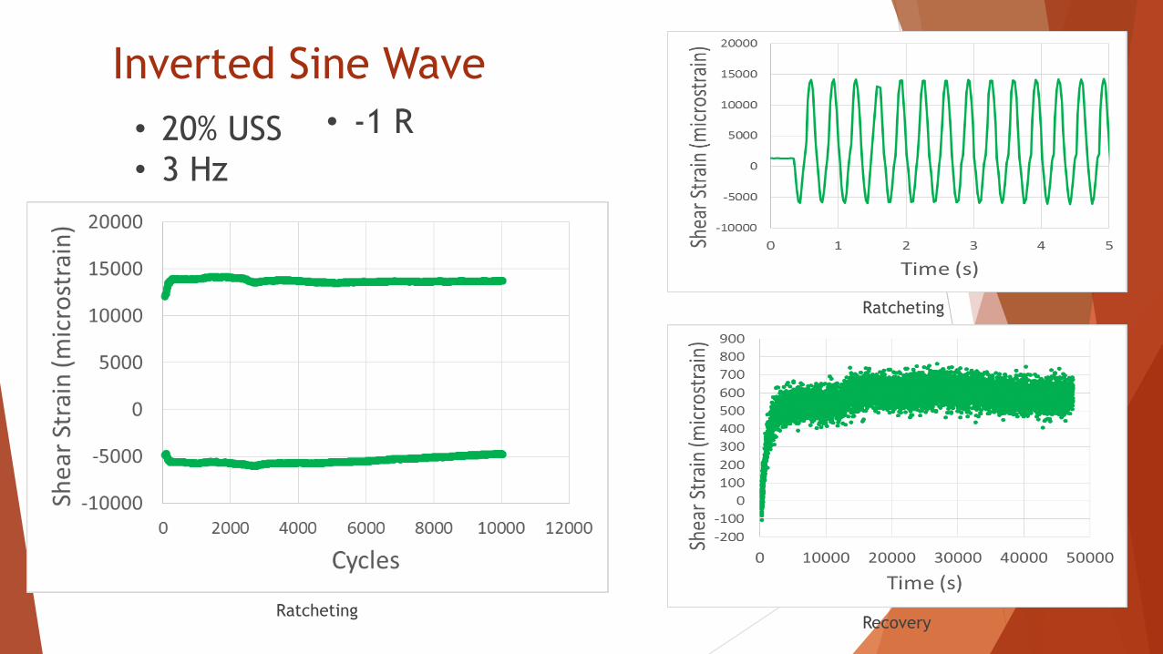
Inverted Sine Wave
Ratcheting
• 20% USS
• 3 Hz
• -1 R
Recovery
Ratcheting

Stress-Strain Hysteresis Loop
0.1 R
-1500
-1000
-500
0
500
1000
1500
-10000 -5000 0 5000 10000 15000 20000
She
ar S
tres
s (p
si)
Shear Strain (microstrain)
3 hz .5 hz 0.15 hz
-1500
-1000
-500
0
500
1000
1500
-0.1 -0.05 0 0.05 0.1 0.15
Shea
r St
ress
(p
si)
Extensometer
3 hz .5 hz 0.15 hz
0
200
400
600
800
1000
1200
1400
0 5000 10000 15000 20000
Shea
r St
ress
(p
si)
Shear Strain (microstrain)
3 hz .5 hz 0.15 hz
-1 R
• 20% USS
• Sine Wave
-1 R

Change in R Ratio
Ratcheting Ratcheting and Recovery
• 50% USS
• 3 Hz
x
• Sine Wave

Maximum Shear Angle y
x
10o
θ
• 50% USS
• 3 Hz
• Sine Wave

50% USS
-1 R
Ratcheting
Ratcheting
Monotonic
Ratcheting until Failure

Questions
50% UTS, R=0.1 (compression)
Similar cyclic and permanent strain as in tension?
Do WALS coupons have response similar to scarf joints?
They also have tension at free edges
Is strain growth associated with material softening (i.e. damage)?
We can now measure modulus during a cyclic test
Is the maximum shear angle a measure of damage?
We need more data
What can the failure surface tell us?
Adhesive failure vs. primer failure

Test Matrix
EA9696 0.1 R 10,000 Cycles EA9696 3 Hz 10,000 Cycles
Frequency (Hz) R ratio
0.05 3.00 5.00 -1.00 -0.50 0.10 0.90
Stress (% Ultimate
Shear Strength)
80% 0/3 0/3 0/3Stress
(% Ultimate Shear Strength)
50% 2/3 1/3 2/3 1/3
50% 2/3 2/3 1/3 20% 3/3 2/3
20% 1/3 2/3
FM300-2 0.1 R 10,000 Cycles FM300-2 3 Hz 10,000 Cycles
Frequency (Hz) R ratio
0.05 3.00 5.00 -1.00 -0.50 0.10 0.90
Stress (% Ultimate
Shear Strength)
80% 0/3 0/3 0/3Stress
(% Ultimate Shear Strength)
50% 0/3 0/3 0/3 0/3
50% 0/3 0/3 0/3 20% 0/3 0/3
20% 0/3 0/3
Finished In Progress Not Started

Nonlinear Viscoplastic Model
• History Models
ABAQUS Models
•Two-layer viscoplasticity
•Linear viscoelasticity
•Parallel Rheological Framework
ABAQUS User Subroutine + UMAT
• 𝜀 𝑡 =
∞−𝑡𝐷0𝑒
𝑡−𝜏
𝑡0
𝑚
ሶ𝜎 𝜏 ⅆ𝜏
UMAT
•Nonlinear Viscoelasticity + Nonlinear Plasticity
• No time-dependent
for recovery stage
• No permanent strain
• Bad prediction for
long term creep and
recovery strain
• No time-dependent
for recovery stage

Popular Nonlinear Viscoplastic Models
Viscoplastic Models Comparison• Raghava Model
𝑓 =𝜂−1 𝐼1+ 𝜂−1 2𝐼1
2+12𝜂𝐽2
2𝜂− 𝜎𝑡 − 𝑅 𝑘
𝜂 – viscosity parameter𝜎𝑡 - yield stress in uniaxial tension𝑅 𝑘 - hardening rule
• Zapas- Crissman Model
𝜀𝑣𝑝 = 𝐶න0
𝑡
𝜎𝑁 ⅆ𝜏
𝑀
𝐶, 𝑁, 𝑀 – temperature dependent parameters
• Both models had limited ability to describe plasticity.

Nonlinear Viscoplastic Model
Total Strain:
ε = 𝜀𝑣𝑒 + 𝜀𝑣𝑝
VE- Schapery Model
𝜀𝑣𝑒 𝑡 = 𝑔0𝐷0𝜎𝑡 + 𝑔1 0
𝑡∆𝐷 𝜓𝑡−𝜓𝜏 𝑑 𝑔2𝜎
𝜏
𝑑𝜏ⅆ𝜏
𝜓𝑡 =𝑡
𝑎
Δ𝐷𝜓𝑡= σ𝑛=1
𝑁 𝐷𝑛 1 − exp −𝜆𝑛𝜓𝑡
𝑔0, 𝑔1, 𝑔2, 𝑎 - nonlinear parameters dependent on stress at current time t, 𝜎𝑡
𝐷0, 𝐷𝑛 , 𝜆𝑛 – parameters in Prony series, here this project has 7 branches in Prony (i.e. n=7)

Nonlinear Viscoplastic Model
VP- Perzyna Model
ሶ𝜀𝑣𝑝 = ሶ𝜆𝑚 = 𝜂 𝜙 𝑓𝜕𝑔
𝜕𝜎𝑖𝑗= 𝜂
𝑓
𝜎𝑦0
𝑁𝜕𝑔
𝜕𝜎𝑖𝑗
Where,
𝜂 – viscosity parameter
N - constant
• 𝒇 yield stress
Yield Surface Hardening Associated/Non Associated
Model 1 Drucker-Prager Nonlinear Isotropic Associated (f=g)
Model 2 Von Mises Nonlinear Kinematic Associated (f=g)
Model 2:
𝑓 = 𝜎𝑒 − 𝜎𝑦0 =
3
2𝑆𝑖𝑗 − 𝛼 𝑆𝑖𝑗 − 𝛼 − 𝜎𝑦
0
α =𝑐
𝑘1 − 𝑒−𝑘𝜀𝑒
𝑣𝑝
Model 1:
𝑓 = τ − α𝐼1 − 𝜅 𝜀𝑒𝑣𝑝
=3
2𝑆𝑖𝑗𝑆𝑖𝑗 − 𝛼𝐼1 − 𝜅 𝜀𝑒
𝑣𝑝
𝜅 𝜀𝑒𝑣𝑝
= 𝜅0 + 𝜅1 1 − 𝑒−𝑘𝜀𝑒𝑣𝑝

Nonlinear Viscoelastic-Viscoplastic Model
• Flowchart • Parameters Calibration
Creep data without permanent strain
•Prony series
•VE nonlinear parameters
Uniaxial tension test
•Yield surface and hardening rule
Creep data
•VP parameters

Bulk Coupon EA9696Creep
0
2000
4000
6000
8000
10000
12000
14000
16000
18000
20000
22000
24000
26000
28000
30000
32000
34000
36000
38000
0 2000 4000 6000 8000 10000
Str
ain
(με)
Time (s)
TEST
20% Model
50% Model
80% Model 1
80% Model 2
80% NPL
0
500
1000
1500
2000
2500
3000
3500
4000
4500
5000
5500
6000
10000 30000 50000 70000 90000 110000
Recovery
Str
ain
(με)
Time (S)
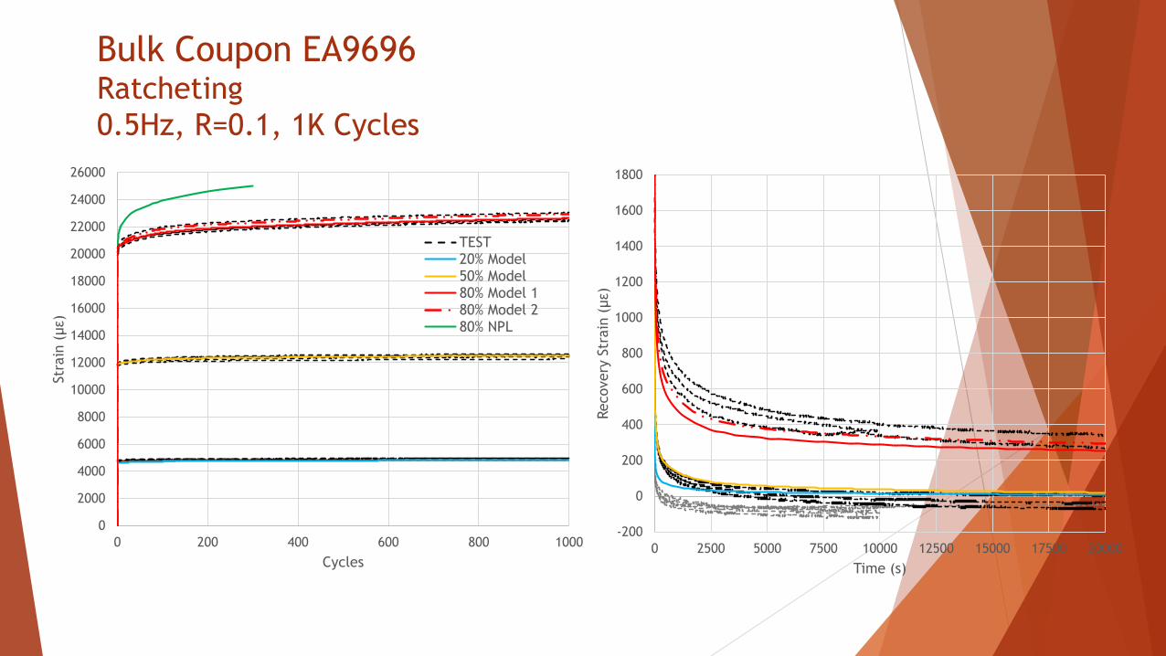
Bulk Coupon EA9696Ratcheting
0.5Hz, R=0.1, 1K Cycles
0
2000
4000
6000
8000
10000
12000
14000
16000
18000
20000
22000
24000
26000
0 200 400 600 800 1000
Str
ain
(με)
Cycles
TEST20% Model50% Model80% Model 180% Model 280% NPL
-200
0
200
400
600
800
1000
1200
1400
1600
1800
0 2500 5000 7500 10000 12500 15000 17500 20000
Recovery
Str
ain
(με)
Time (s)

Bulk Coupon EA9696Ratcheting
0.5Hz, R=0.1, 10K Cycles
0
2000
4000
6000
8000
10000
12000
14000
16000
18000
20000
22000
24000
26000
0 2000 4000 6000 8000 10000
Str
ain
(με)
Cycles
TEST
20% Model
50% Model
80% Model 1
80% Model 2
80% NPL
-300
0
300
600
900
1200
1500
1800
2100
2400
2700
3000
0 15000 30000 45000 60000 75000 90000 105000 120000 135000 150000
Recovery
Str
ain
(με)
Time (s)

Bulk Coupon FM300-2Creep
0
2000
4000
6000
8000
10000
12000
14000
16000
18000
20000
22000
24000
0 2000 4000 6000 8000 10000
Str
ain
(με)
Time (s)
TEST
20% Model
50% Model
80% Model 1
80% Model 2
80% NPL
0
500
1000
1500
2000
2500
3000
3500
4000
10000 20000 30000 40000 50000 60000 70000 80000 90000 100000 110000
Recovery
Str
ain
(με)
Time (s)

Bulk Coupon FM3000-2Ratcheting
0.5Hz, R=0.1, 1K Cycles
0
2000
4000
6000
8000
10000
12000
14000
16000
18000
20000
0 200 400 600 800 1000
Str
ain
(με)
Cycles
TEST
20% Model
50% Model
80% Model 1
80% Model 2
80% NPL
-200
0
200
400
600
800
1000
1200
0 1000 2000 3000 4000 5000 6000 7000 8000 9000 10000Str
ain
(με)
Time (s)

Bulk Coupon FM300-2Ratcheting
0.5Hz, R=0.1, 10K Cycles
0
2000
4000
6000
8000
10000
12000
14000
16000
18000
20000
0 2000 4000 6000 8000 10000
Str
ain
(με)
Cycles
TEST
20% Model
50% Model
80% Model 1
80% Model 2
80% NPL
-200
0
200
400
600
800
1000
1200
1400
1600
1800
0 10000 20000 30000 40000 50000 60000 70000 80000 90000 100000
Recovery
Str
ain
(με)
Time (s)

Conclusion
• Strain gages work surprisingly well in measuring thin bond adhesive strain
• Some adhesives exhibit more cyclic plasticity in shear than normal stress
• Plastic strain can accumulate at low stress (20% UTS)
• Adhesives exhibit viscoelastic and viscoplastic response.
• Parameters calibrated from creep test can predict ratcheting response.
• Plastic rule is more important for multiaxial stress.

Looking Forward
• Benefit to Aviation– Methodology to characterize adhesive plasticity
– Improved models of adhesive time and plastic response
– Adhesive ratcheting behavior
• Future needs– Experiment
– Shear with compression, WALS
– Shear angle, softening, failure surface examination
– Simulation of bonded joints under shear
– Extend current model to 2D plane strain.
– Consider plastic flow rule as non-associated.
– Apply to scarf and WALS adhesive joints.