Ductless Hydronic Distribution...
40
Buildings Technologies Program Date: November 8, 2011 Ductless Hydronic Distribution Systems Welcome to the Webinar! We will start at 1:00 PM Eastern Time Be sure that you are also dialed into the telephone conference call: Dial-in number: 800-779-8694; Pass code: 2506667 Download the presentation at: www.buildingamerica.gov/meetings.html
Transcript of Ductless Hydronic Distribution...

1 | Building America Program www.buildingamerica.gov
Buildings Technologies Program
Date: November 8, 2011
Ductless Hydronic Distribution Systems Welcome to the Webinar! We will start at 1:00 PM Eastern Time
Be sure that you are also dialed into the telephone conference call:
Dial-in number: 800-779-8694; Pass code: 2506667 Download the presentation at: www.buildingamerica.gov/meetings.html
Building Technologies Program eere.energy.gov
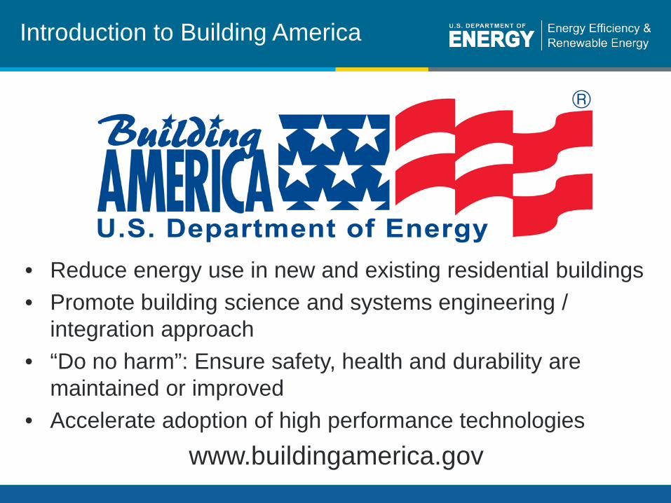
• Reduce energy use in new and existing residential buildings • Promote building science and systems engineering /
integration approach • “Do no harm”: Ensure safety, health and durability are
maintained or improved • Accelerate adoption of high performance technologies
www.buildingamerica.gov
Introduction to Building America
Building Technologies Program eere.energy.gov
Building America Industry Consortia Industry Research Teams
Habitat Cost Effective Energy Retrofit Program
NorthernSTAR Building America Partnership
Building Energy Efficient Homes for America (BeeHa)
Building Technologies Program eere.energy.gov
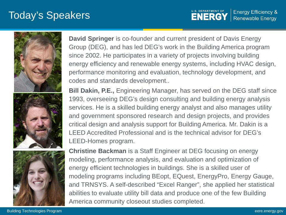
Today’s Speakers
David Springer is co-founder and current president of Davis Energy Group (DEG), and has led DEG’s work in the Building America program since 2002. He participates in a variety of projects involving building energy efficiency and renewable energy systems, including HVAC design, performance monitoring and evaluation, technology development, and codes and standards development.. Bill Dakin, P.E., Engineering Manager, has served on the DEG staff since 1993, overseeing DEG’s design consulting and building energy analysis services. He is a skilled building energy analyst and also manages utility and government sponsored research and design projects, and provides critical design and analysis support for Building America. Mr. Dakin is a LEED Accredited Professional and is the technical advisor for DEG’s LEED-Homes program. Christine Backman is a Staff Engineer at DEG focusing on energy modeling, performance analysis, and evaluation and optimization of energy efficient technologies in buildings. She is a skilled user of modeling programs including BEopt, EQuest, EnergyPro, Energy Gauge, and TRNSYS. A self-described “Excel Ranger”, she applied her statistical abilities to evaluate utility bill data and produce one of the few Building America community closeout studies completed.
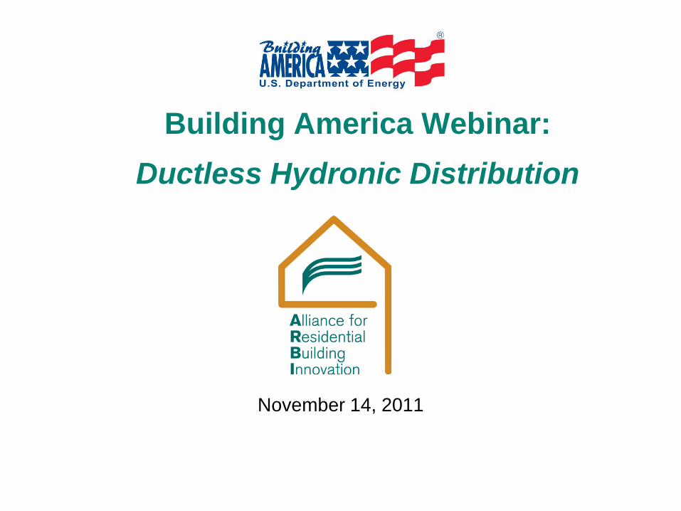
Building America Webinar:
Ductless Hydronic Distribution
November 14, 2011

2
The ARBI Team
…plus multiple industry partners
3
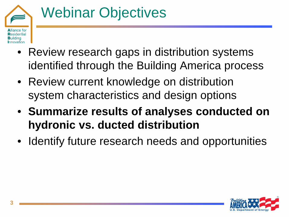
Webinar Objectives
• Review research gaps in distribution systems identified through the Building America process
• Review current knowledge on distribution system characteristics and design options
• Summarize results of analyses conducted on hydronic vs. ducted distribution
• Identify future research needs and opportunities
4
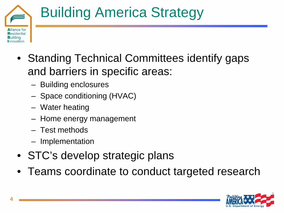
Building America Strategy
• Standing Technical Committees identify gaps and barriers in specific areas: – Building enclosures – Space conditioning (HVAC) – Water heating – Home energy management – Test methods – Implementation
• STC’s develop strategic plans • Teams coordinate to conduct targeted research

5
Gaps Identified by HVAC STC
• Heating & Cooling Equipment – Lack of availability of small capacity heating & cooling
systems – Excessive fan energy use
• Distribution – Low cost space conditioning distribution strategies for
low load homes – Effectiveness of zoned systems
6
Primary HVAC Issues
• Ducts in non-conditioned spaces (esp. attics) have a low distribution efficiency and alternatives are costly: – Creating non-vented, conditioned attics or interior chases for
ducts – Multi-split variable refrigerant flow systems
• Most conventional equipment is oversized for houses with small loads – Cycling losses – Poor humidity control in humid climates
• Forced air zoning is problematic – Systems cannot vary airflow capacity with the number of zones
calling for heating or cooling – Duct over-sizing, dump zones, and/or bypass dampers
compromise efficiency
7
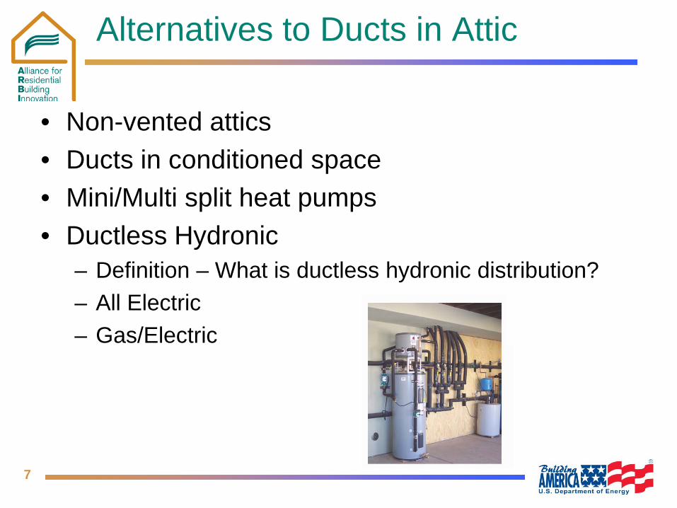
Alternatives to Ducts in Attic
• Non-vented attics • Ducts in conditioned space • Mini/Multi split heat pumps • Ductless Hydronic
– Definition – What is ductless hydronic distribution? – All Electric – Gas/Electric
8
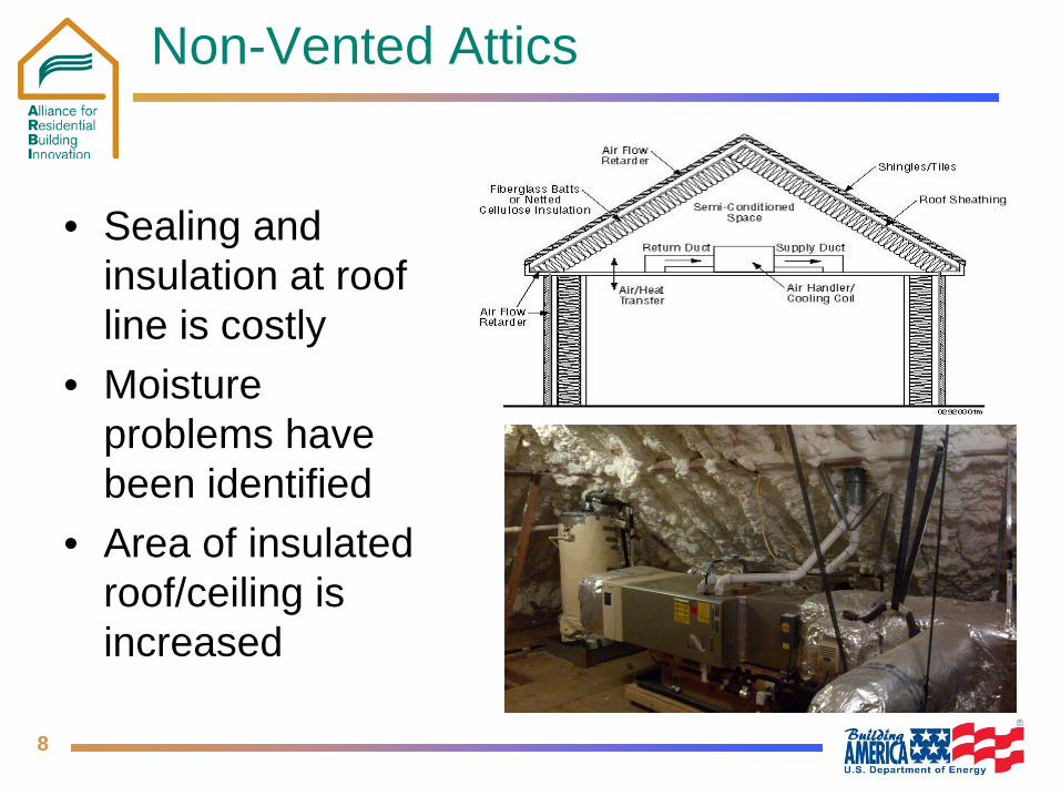
Non-Vented Attics
• Sealing and insulation at roof line is costly
• Moisture problems have been identified
• Area of insulated roof/ceiling is increased
9
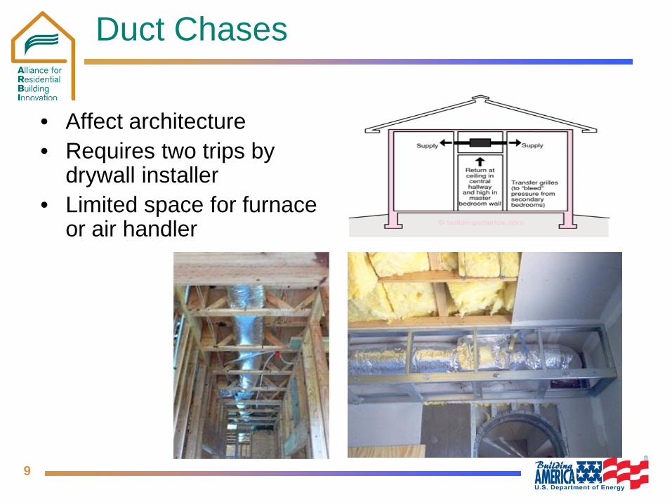
Duct Chases
• Affect architecture • Requires two trips by
drywall installer • Limited space for furnace
or air handler
10
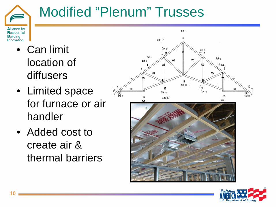
Modified “Plenum” Trusses
• Can limit location of diffusers
• Limited space for furnace or air handler
• Added cost to create air & thermal barriers
11
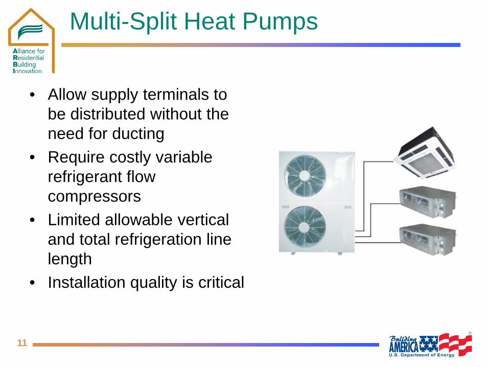
Multi-Split Heat Pumps
• Allow supply terminals to be distributed without the need for ducting
• Require costly variable refrigerant flow compressors
• Limited allowable vertical and total refrigeration line length
• Installation quality is critical
12
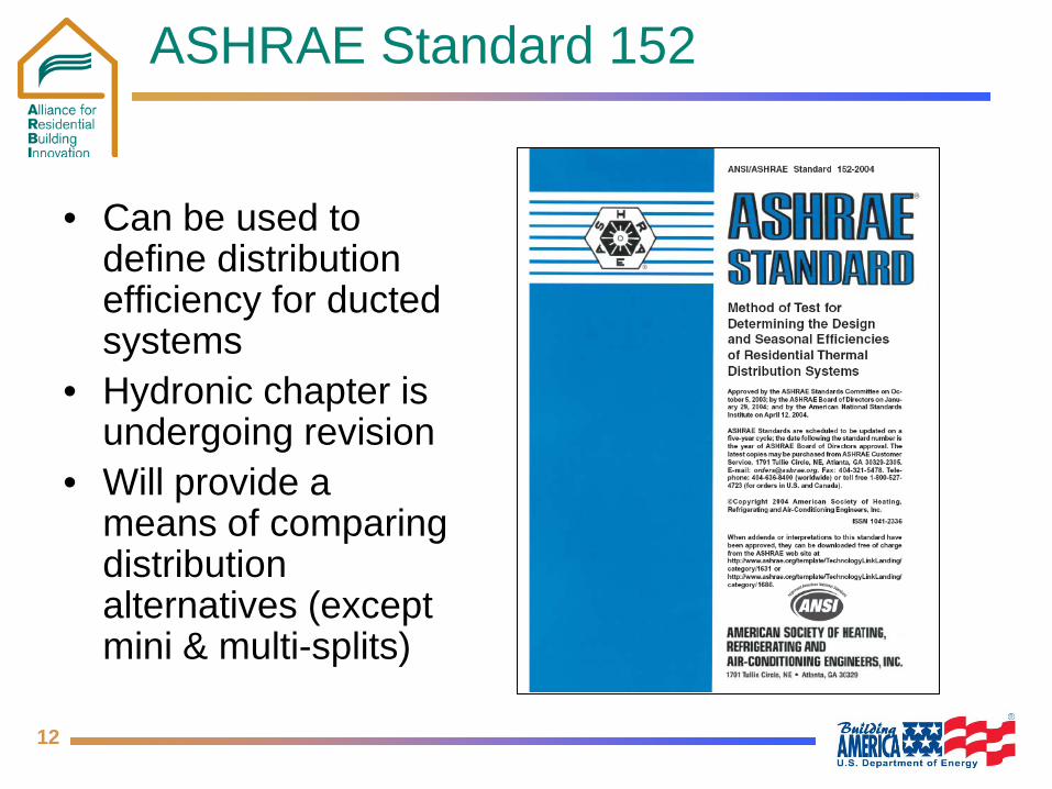
ASHRAE Standard 152
• Can be used to define distribution efficiency for ducted systems
• Hydronic chapter is undergoing revision
• Will provide a means of comparing distribution alternatives (except mini & multi-splits)
13
Project Hypothesis
• Hydronic distribution offers a better value proposition than ducts: – Lower heat losses from conduits (pipes vs. ducts) – Less energy required to move fluid (pumps vs. fans) – Easier to seal against leakage – Pipes can be routed under attic insulation or through
framing without modifying the structure – Easier to transport and install pipes than ducts – Easier to zone – Potential for off-peak storage and integration with
solar and heat recovery

14
Duct vs. Pipe Heat Loss
• Assume 5,000 Btuh of cooling delivery • Ducted Air Delivery
Р167 cfm 8ӯ duct = 12.8 Btuh thermal loss
• Hydronic Chilled Water Delivery – 0.7 gpm ½”Ø pipe = 4.6 Btuh thermal loss (64% Savings)
DUCT PIPE
15
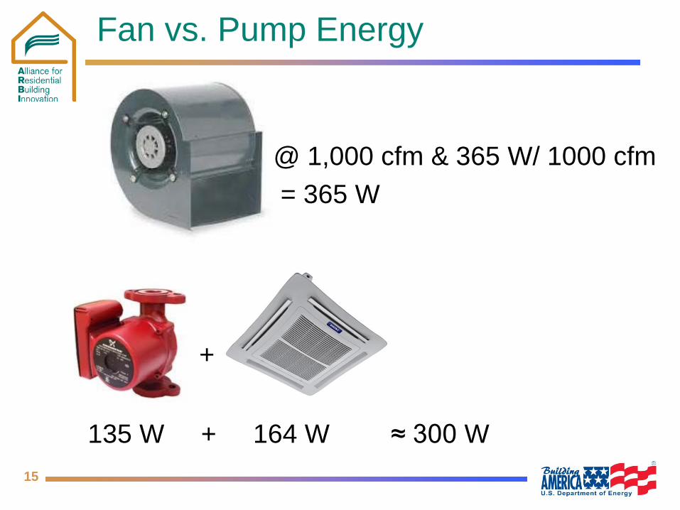
Fan vs. Pump Energy
@ 1,000 cfm & 365 W/ 1000 cfm = 365 W
135 W + 164 W ≈ 300 W
+
16
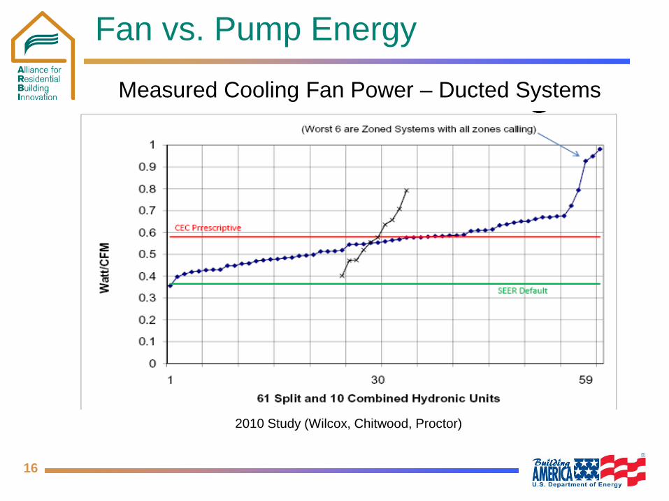
Fan vs. Pump Energy
Measured Cooling Fan Power – Ducted Systems
2010 Study (Wilcox, Chitwood, Proctor)
17
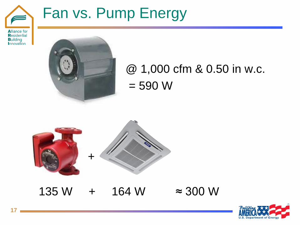
Fan vs. Pump Energy
@ 1,000 cfm & 0.50 in w.c. = 590 W
135 W + 164 W ≈ 300 W
+

18
Terminal Delivery Options
Delivery Options Load Type"Pancake" fan coil or ceiling cassette Heating or CoolingBaseboard Convector Heating OnlyWall Radiators Heating OnlyCeiling Panels Heating or CoolingSlab-on-Grade Radiant Floor Heating or Cooling*Raised Foundation Radiant Floor Heating OnlyValence Heating or Cooling *Dry climates with exposed concrete or tile floors only
19
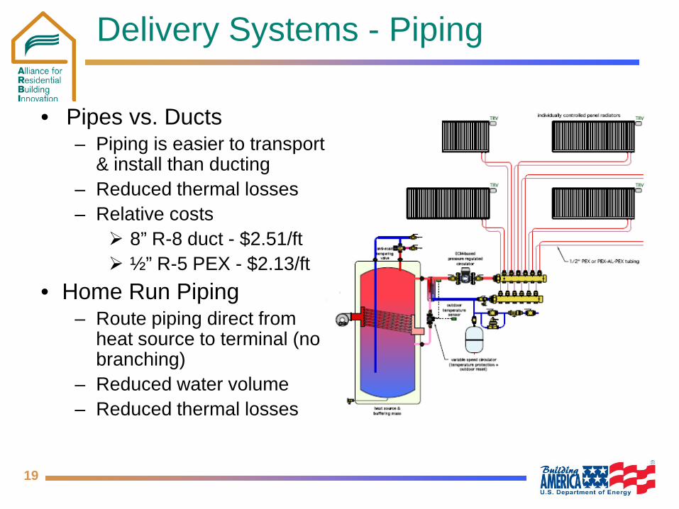
Delivery Systems - Piping
• Pipes vs. Ducts – Piping is easier to transport
& install than ducting – Reduced thermal losses – Relative costs
8” R-8 duct - $2.51/ft ½” R-5 PEX - $2.13/ft
• Home Run Piping – Route piping direct from
heat source to terminal (no branching)
– Reduced water volume – Reduced thermal losses
20
Hot-Chilled Water Sources
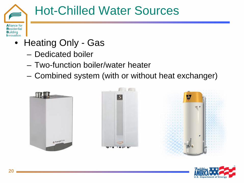
• Heating Only - Gas – Dedicated boiler – Two-function boiler/water heater – Combined system (with or without heat exchanger)
21
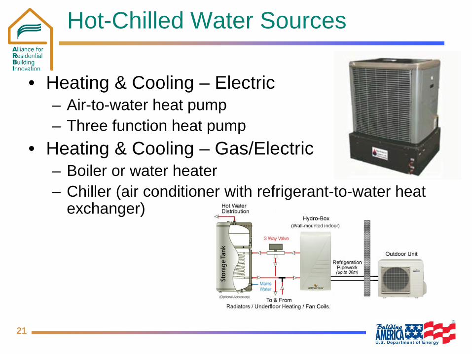
Hot-Chilled Water Sources
• Heating & Cooling – Electric – Air-to-water heat pump – Three function heat pump
• Heating & Cooling – Gas/Electric – Boiler or water heater – Chiller (air conditioner with refrigerant-to-water heat
exchanger)
22
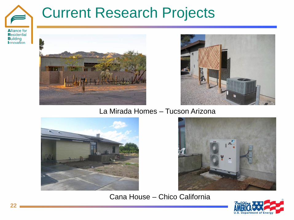
Current Research Projects
La Mirada Homes – Tucson Arizona
Cana House – Chico California
23
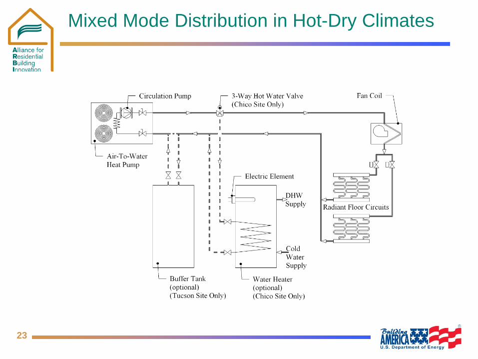
Mixed Mode Distribution in Hot-Dry Climates
24
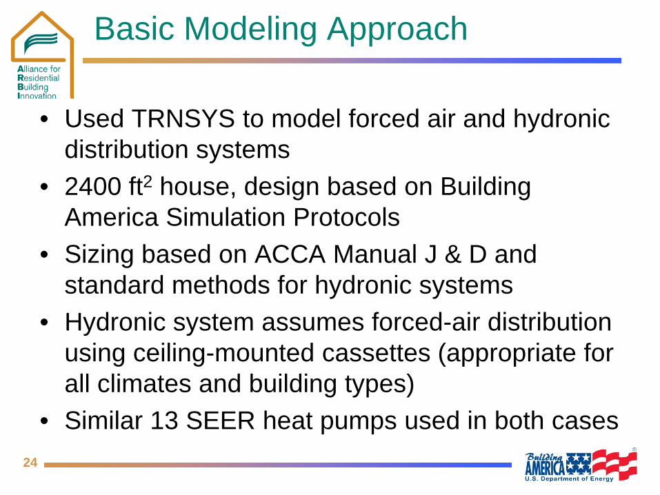
Basic Modeling Approach
• Used TRNSYS to model forced air and hydronic distribution systems
• 2400 ft2 house, design based on Building America Simulation Protocols
• Sizing based on ACCA Manual J & D and standard methods for hydronic systems
• Hydronic system assumes forced-air distribution using ceiling-mounted cassettes (appropriate for all climates and building types)
• Similar 13 SEER heat pumps used in both cases
25
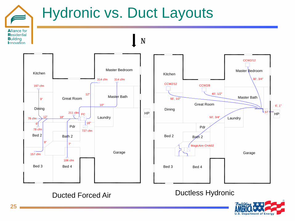
Hydronic vs. Duct Layouts
N
Kitchen
Dining
Bed 2
Bed 3 Bed 4
Bath 2
Pdr
Laundry
Master Bedroom
Master Bath
Great Room
30', 3/4"
50', 3/4"
55', 1/2"
40', 1/2"
HPST
Garage
6', 1"
CCW2/12
CCW2/12
CCW2/8
MagicAire CHA02
Kitchen
Dining
Bed 2
Bed 3 Bed 4
Bath 2
Pdr
Laundry
Master Bedroom
Master BathGreat Room
FC HP
Garage
78 cfm
157 cfm
106 cfm
78 cfm
197 cfm
211 cfm
314 cfm314 cfm
727 cfm
18"
7"9"
6"
9"
12"
10"
12"
16"
Ductless Hydronic Ducted Forced Air

26
Energy Use Comparison - Methods
TRNSYS Model • Base Case
– Forced air ducted system
– Single zone • 1 thermostat
– Air to air heat pump – Blower Fan
• 900 CFM • 327 W

27
Energy Use Comparison - Methods
TRNSYS Model • Ductless Hydronic
– 4 Ceiling Cassettes • Airdale Model – 250 CFM/room – 0.14 CFM/Watt
– Single zone • 1 thermostat
– Air to-water heat pump
• Altherma specs

28
Energy Use Comparison - Results
-
1,000
2,000
3,000
4,000
5,000
6,000
7,000
8,000
9,000
10,000
Ducted Forced Air System (Ducts in Attic)
Ducted Forced Air System (Ducts in Zone)
Ductless Ceiling Cassette (Single Zone)
Annu
al E
lect
ricity
Use
(kW
h/yr
)
Annual Fan and Pump (kWh/yr)
Annual Cooling (kWh/yr)
Annual Heating (kWh/yr)
8,844
7,316
5,376

29
Delivery Efficiency
Distribution Energy Savings
Delivered Energy by Heat Pump (MBtu/yr)
Fan and Pump Energy (kWh/yr)
Ducts in Attic 56.0 972.8
Ductless 47.7 714.9
% Savings 15% 27%
30
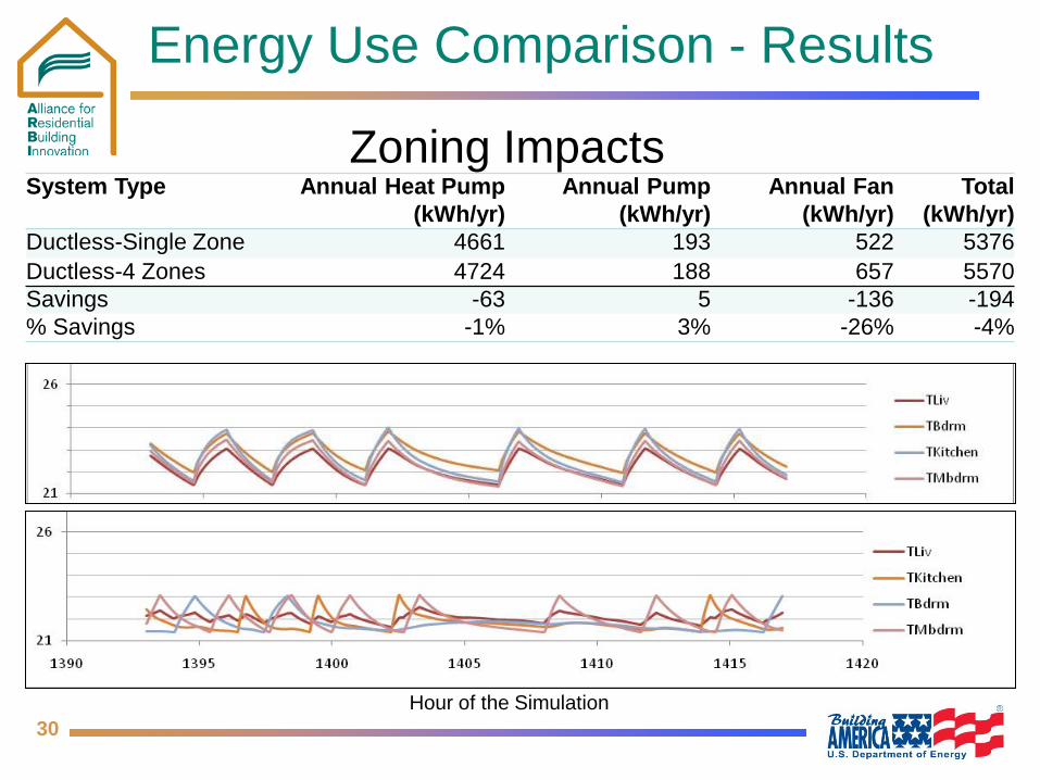
Energy Use Comparison - Results
Zoning Impacts System Type Annual Heat Pump
(kWh/yr) Annual Pump
(kWh/yr) Annual Fan
(kWh/yr) Total
(kWh/yr) Ductless-Single Zone 4661 193 522 5376 Ductless-4 Zones 4724 188 657 5570 Savings -63 5 -136 -194 % Savings -1% 3% -26% -4%
Hour of the Simulation

31
Further Modeling Objectives
• Generic Air-to-Water Heat Pump model • Delivery Methods-Radiant Floor or Ceiling
Panels • Climate Zone Impacts • Building Load Impacts

32
Estimated Savings
System Type Annual Heating
(kWh/yr)
Annual Cooling
(kWh/yr)
Annual Fan and Pump (kWh/yr)
Total (kWh/yr)
Ducted Forced Air System (Ducts in Attic)
6,967 944 933 8,844
Ductless Ceiling Cassette (Single Zone)
4,139 522 715 5,376
Estimated Annual Savings 3,468
Estimated Annual Cost Savings $390
Cost savings based on $0.113/kWh (National Avg. Electricity Rate)
33
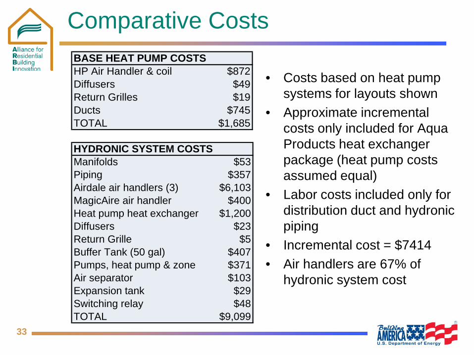
Comparative Costs
• Costs based on heat pump systems for layouts shown
• Approximate incremental costs only included for Aqua Products heat exchanger package (heat pump costs assumed equal)
• Labor costs included only for distribution duct and hydronic piping
• Incremental cost = $7414 • Air handlers are 67% of
hydronic system cost
BASE HEAT PUMP COSTSHP Air Handler & coil $872Diffusers $49Return Grilles $19Ducts $745TOTAL $1,685
HYDRONIC SYSTEM COSTSManifolds $53Piping $357Airdale air handlers (3) $6,103MagicAire air handler $400Heat pump heat exchanger $1,200Diffusers $23Return Grille $5Buffer Tank (50 gal) $407Pumps, heat pump & zone $371Air separator $103Expansion tank $29Switching relay $48TOTAL $9,099
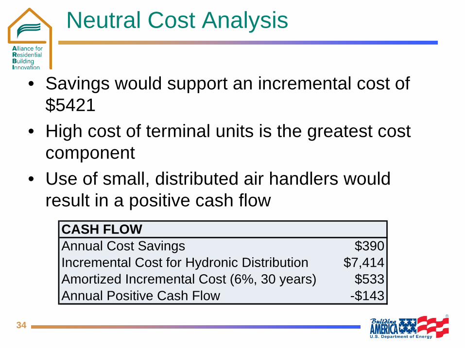
34
Neutral Cost Analysis
• Savings would support an incremental cost of $5421
• High cost of terminal units is the greatest cost component
• Use of small, distributed air handlers would result in a positive cash flow
CASH FLOWAnnual Cost Savings $390Incremental Cost for Hydronic Distribution $7,414Amortized Incremental Cost (6%, 30 years) $533Annual Positive Cash Flow -$143

35
Summary
• Simulations show significant energy savings relative to ducted systems
• Additional savings may result from zoning • Equipment gap: inexpensive, ceiling-mounted forced
air terminal units • Radiant floor distribution would likely cost less than
the specified forced air units • Additional product offerings and increased volume
would improve market viability • Trades would need to adapt to provide both
plumbing and HVAC services

36
Next Steps
• Evaluate for different climates • Comparative field test of systems
– Radiant floor distribution (in process) – Forced air distribution
• Work with TESS on TRNSYS model verification • Develop performance maps for air-to-water heat
pumps