
China Tape,Teflon Tape,PVC Electrical Insulation Tape,Packing Tape,PTFE Thread Seal Tape,Duct Tape

Arnold Schwarzenegger Governor
Duct Tape Durability Testing
Prepared For: California Energy Commission Public Interest Energy Research Program
Prepared By: Lawrence Berkeley National Laboratory
PIER
FIN
AL
PRO
JEC
T R
EPO
RT
JANUARY 2005
CEC-500-2005-008

Prepared By: Lawrence Berkeley National Laboratory
M.H. Sherman Berkeley, CA Contract No. 500-99-013 Prepared For:
California Energy Commission Public Interest Energy Research (PIER) Program
Phil Spartz, Contract Manager Nancy Jenkins, Program Area Team Lead Buildings End-Use Energy Efficiency Ron Kukulka, Acting Deputy Director ENERGY RESEARCH AND DEVELOPMENT
DIVISION Robert L. Therkelsen Executive Director
DISCLAIMER This report was prepared as the result of work sponsored by the
California Energy Commission. It does not necessarily represent the views of the Energy Commission, its employees or the State of California. The Energy Commission, the State of California, its employees, contractors and subcontractors make no warrant, express or implied, and assume no legal liability for the information in this report; nor does any party represent that the uses of this information will not infringe upon privately owned rights. This report has not been approved or disapproved by the California Energy Commission nor has the California Energy Commission passed upon the accuracy or adequacy of the information in this report.

LEGAL NOTICE This work was supported by the Assistant Secretary for Energy Efficiency and Renewable Energy, Building Technologies Program, of the U.S. Department of Energy under contract No. DE-AC03-76SF00098. The research reported here was also funded by the California Institute for Energy Efficiency (CIEE), a research unit of the University of California, under Memorandum Agreement C-03-11, Interagency Agreement No. 500-99-013 with the California Energy Commission. Publication of research results does not imply CIEE endorsement of or agreement with these findings, nor that of any CIEE sponsor.
i

PREFACE The Public Interest Energy Research (PIER) Program supports public interest energy research and development that will help improve the quality of life in California by bringing environmentally safe, affordable and reliable energy services and products to the marketplace.
The PIER program, managed by the California Energy Commission (Energy Commission), annually awards up to $62 Million to conduct the most promising public interest energy research by partnering with Research, Development and Demonstration (RD&D) organizations, including individuals, businesses, utilities, and public or private research institutions.
• PIER funding efforts are focused on the following six RD&D program areas: • Buildings End-Use Energy Efficiency • Industrial/Agricultural/Water End-Use Energy Efficiency • Renewable Energy • Environmentally-Preferred Advanced Generation • Energy Related Environmental Research • Strategic Energy Research
What follows is the final report for the Advanced Duct Sealant Testing, work authorization No. 49, Interagency Agreement No. 500-99-013 conducted by the Lawrence Berkeley National Laboratory. This report is entitled Advanced Duct Sealing. This project contributes to the Buildings End-Use Energy Efficiency program.
For more information on the PIER Program, please visit the Energy Commission's Web site at: http://www.energy.ca.gov/research/index.html or contact the Energy Commission's Publications Unit at 916-654-5200.
ii

ABSTRACT Duct leakage is a major source of energy loss in residential buildings. Most duct leakage occurs at the connections to registers, plenums, or branches in the duct system. At each of these connections, a method of sealing the duct system is required. Typical sealing methods include tapes or mastics applied around the joints in the system. Field examinations of duct systems have shown that taped seals tend to fail over extended periods of time. The Lawrence Berkeley National Laboratory (LBNL) has been testing sealant durability for several years using accelerated test methods and found that typical duct tape (i.e., cloth-backed tapes with natural rubber adhesives) fails more rapidly than other duct sealants. The test results for collar-to-plenum connections showed that the current UL testing and certification program is not sufficient for indicating durability and many tapes showed significant failure when testing using UL 181B procedures. The current study focused on evaluating UL181B-FX duct sealants on round flex duct to sheet metal collar connections that placed less stress on the joint to be sealed. After two years of testing, the flex-to-collar connections showed little change in air leakage, but substantial visual degradation from some products. A surprising result from the testing was that most of the clamps used to mechanically fasten the connections failed during the testing. This indicates that the durability of clamps also need to be evaluated to ensure longevity of the duct connection. Testing also included advanced tape products being developed by major manufacturers on a collar-to-plenum connection as used in previous studies. The advanced tape performed better than previously tested cloth backed tapes and failed after about 60 days of testing. During this study we completed an ASTM standard (E2342-03) for evaluating the durability of duct sealants using the collar-to-plenum connection.
Keywords: ducts, air leakage, duct tape, durability, longevity, UL 181 B
iii

TABLE OF CONTENTS Abstract ......................................................................................................................................................iii
Executive Summary..................................................................................................................................iv
1.0 Introduction ................................................................................................................................... 3
2.0 Project Approach........................................................................................................................... 7
3.0 Project Outcomes ........................................................................................................................ 17
4.0 Conclusions and Recommendations ........................................................................................ 29
4.1. Implications for Title 24, Part 6............................................................................................. 30
References ................................................................................................................................................. 32
Appendix A: Examples of Visual Deterioration ...................................................................................A
Appendix B: Initial and Final Photographs of Test Samples ...............................................................B
Appendix C: Notice of Committee Conclusions .................................................................................. C
LIST OF FIGURES Figure 1 Example Of Collar-To-Plenum Connections On A System Where The Tape Sealant Has
Fallen Off ............................................................................................................................................. 5
Figure 2 A Collection Of Collar-To-Plenum Test Samples From LBNL ............................................ 5
Figure 3 Example Of A Core-To-Collar Test Sample Showing The Two Taped Connections And The Mechanical Clamps .................................................................................................................... 8
Figure 4 A Side-View Schematic Of A Flexible Duct Core To Sheet Metal Collar Joint Specimen Positioned On The Aging Test Apparatus ..................................................................................... 9
Figure 5 One Chamber Of The High Temperature Aging Test Apparatus ..................................... 10
Figure 6 Leakage Test Device For Pressurizing Test Samples. Test Sample Is A Collar-To-Plenum Joint ..................................................................................................................................... 11
Figure 7 Decay In The Measured Leakage As The Specimen Cools Down From 200F (93°C) To Room Temperature .......................................................................................................................... 13
Figure 8 High Temperature Baking Apparatus................................................................................... 14
Figure 9 Before Testing............................................................................................................................ 14
Figure 10 After Four Weeks Of Testing ................................................................................................ 15
Figure 11 Before Testing.......................................................................................................................... 15
Figure 12 After Three Weeks Of Testing .............................................................................................. 15
iv
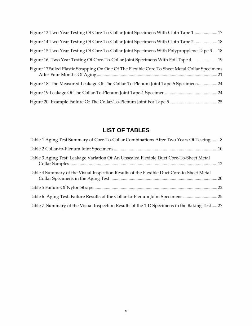
Figure 13 Two Year Testing Of Core-To-Collar Joint Specimens With Cloth Tape 1 .................... 17
Figure 14 Two Year Testing Of Core-To-Collar Joint Specimens With Cloth Tape 2 .................... 18
Figure 15 Two Year Testing Of Core-To-Collar Joint Specimens With Polypropylene Tape 3 .... 18
Figure 16 Two Year Testing Of Core-To-Collar Joint Specimens With Foil Tape 4....................... 19
Figure 17Failed Plastic Strapping On One Of The Flexible Core To Sheet Metal Collar Specimens After Four Months Of Aging.......................................................................................................... 21
Figure 18 The Measured Leakage Of The Collar-To-Plenum Joint Tape-5 Specimens................. 24
Figure 19 Leakage Of The Collar-To-Plenum Joint Tape-1 Specimen.............................................. 24
Figure 20 Example Failure Of The Collar-To-Plenum Joint For Tape 5 .......................................... 25
LIST OF TABLES
Table 1 Aging Test Summary of Core-To-Collar Combinations After Two Years Of Testing........ 8
Table 2 Collar-to-Plenum Joint Specimens........................................................................................... 10
Table 3 Aging Test: Leakage Variation Of An Unsealed Flexible Duct Core-To-Sheet Metal Collar Samples.................................................................................................................................. 12
Table 4 Summary of the Visual Inspection Results of the Flexible Duct Core-to-Sheet Metal Collar Specimens in the Aging Test .............................................................................................. 20
Table 5 Failure Of Nylon Straps............................................................................................................. 22
Table 6 Aging Test: Failure Results of the Collar-to-Plenum Joint Specimens .............................. 25
Table 7 Summary of the Visual Inspection Results of the 1-D Specimens in the Baking Test ..... 27
v

EXECUTIVE SUMMARY Duct leakage has been identified as a major source of energy loss in residential buildings. Most duct leakage occurs at the connections to registers, plenums or branches in the duct system. At each of these connections a method of sealing the duct system is required. Typical sealing methods include tapes or mastics applied around the joints in the system. Field examinations of duct systems have typically shown that these seals tend to fail over extended periods of time. The Lawrence Berkeley National Laboratory has been testing sealant durability for several years. Typical duct tape (i.e. cloth-backed tape with natural rubber adhesive) was found to fail more rapidly than all other duct sealants.
This report summarizes the results of duct sealant durability testing of five UL 181B-FX listed duct tapes (three cloth tapes, a foil tape and an Oriented Polypropylene (OPP) tape) in three test configurations using a new protocol. In the first configuration, four tapes were tested on a standard flex duct core-to-collar connection. One of the cloth tapes was specifically developed in collaboration with a tape manufacturer to perform better in our durability testing. This new cloth tape was tested in the second configuration on a collar-to-plenum connection (as used in ASTM E2342-03) so that its performance could be compared to products tested in previous studies. The third configuration consisted of baking duct tape specimens in a constant 212°F (100°C) oven following the UL 181B-FX “Temperature Test” requirements. The study is a continuation of ongoing research at Lawrence Berkeley National Laboratory (Sherman and Walker, 2003; Walker and Sherman 2003; Walker and Sherman 2000; Sherman and Walker, 1998) that has the following objectives and outcomes:
Objectives Outcomes
Evaluate existing UL 181B-FX rated tape products on core-to-collar connections for two years.
The core-to-collar connections had no significant failures in terms of leakage. Some showed significant visual degradation. This method was not deemed a good predictor of actual performance1. Most of the standard nylon straps2 failed before the two year test period was completed.
Evaluate the UL 181B-FX high temperature test.
All the UL 181B-FX rated tapes except the foil tape showed significant visual degradation. This indicates that the interpretive nature of UL 181 B-FX high temperature test makes UL 181 B-FX an unreliable indicator of sealant performance.
Evaluate new duct sealant product on a collar-to-plenum connection.
The new duct sealant tape showed improved performance on collar-to-plenum joints, but still failed after 60 days of testing.
Develop a standardized test method for evaluating duct sealant durability.
An American Society for Testing and Materials (ASTM) standard (E2342-03) has been developed that will standardize test procedures and increase reliability of testing.
Key Project Conclusions:
1 The core-to-collar connections did not place any mechanical stress on the tape. Previous LBNL field research (confirmed by many practitioners) has observed that many failed connections have mechanical stresses on the connections.
2 The terms “fastener”, “clamp”, “strap”, “drawband”, “strapping system” and “clamping system” are all used to described mechanical fastening of flex-duct material to the metal collar. Different references and standards use these terms and we do not make any distinctions between them in this report.

When ideally installed on round core-to-collar connections that do not place any mechanical stress on the joint, the UL181B-FX tapes tested do not show substantial increase in air leakage, but have substantial visual degradation. This result, however, is not applicable to California construction practices.
ASTM E2342-03 is a superior test method for determining sealant longevity than the core-to-collar test procedure that formed the majority of testing for this report because it better addresses durability requirements.
The new duct tape is an improvement over other cloth-backed tapes, but still fails in collar-to-plenum testing.
An unexpected discovery of the research was that the standard (non-metallic) core-to-collar clamps have unacceptable high temperature performance. The new UL 181B testing of clamps does not adequately address this issue.
Recommendations:
At the next appropriate standards revision cycle the following changes should be considered:
• Use of cloth back rubber adhesive tapes in Title 24 should be prohibited unless they pass an ASTM E2342 test for a period of at least 60 days.
• Straps must be rated for continuous use at a temperature of at least 200°F. These ratings are available in manufacturers product literature and refer to UL 2043 (“Fire Test for Heat and Visible Smoke Release for Discrete Products and Their Accessories Installed in Air-Handling Spaces”) and other UL and ASTM ratings.
• Industry installation recommendations (e.g., ADC (2003)) must be followed. • A new test method for determining the durability of clamping systems should be developed in
order to test the actual failure modes found in the field. Such a test could be incorporated in the UL testing or be a separate ASTM (or equivalent ANSI) test method.
The Benefits To California From The Work In This Study Are:
• Retention of existing code language that restricts the use of typical duct tapes in California . • Development and approval of an ASTM standard that the Commission (and other building code
authorities) can use to ensure the durability of duct sealants in California buildings. • Development of improved duct sealants that can be used in California buildings. • Increased awareness of duct sealing issues by the California building industry.
2

1.0 Introduction
Background
Air leakage in ducts has been identified as a major source of energy loss in residential buildings. Thirty to forty percent of air flow leaks into and out of ducting systems in residential buildings, and most of the duct leakage occurs at the connections to registers, plenums or branches in the air distribution system (Walker and Sherman 2000). The present study was a continuation of previous studies conducted at LBNL (Walker et al. 1998, Walker and Sherman 1998, Walker and Sherman 2000, Sherman et al. 2000, and especially Sherman and Walker 2003), with the objective of developing new test methods for duct sealant durability, evaluating different sealant types (e.g., tape, mastic, aerosol), facilitating the development of consensus standards (e.g., ASTM), and promoting technology transfer to improve industry practice.
Underwriters Laboratory (UL) have developed standards for closure systems for use with rigid air ducts and air connectors, and flexible air duct and air connectors; UL 181A and UL 181B, respectively (UL 1993 and 2003). The current UL 181B standard deals with field assembled flexible duct systems and is of special importance to residential buildings since residential duct systems in the U.S. are normally field assembled. The standard covers pressure sensitive tapes, mastics and (in the latest 2003 version) fasteners3. The UL 181B standard only applies to tapes to be used on flex duct core-to-collar connections in conjunction with a mechanical clamp. Six tests are prescribed for pressure sensitive tape: tensile strength, peel adhesion at 180° angle, shear adhesion, surface burning, mold growth and humidity, and temperature tests. However, the standard has very limited tests of the durability of duct sealants. For example, the “shear adhesion test” requires duct tape to sustain a specified load without evidence of separation or slippage in excess of 1/8 in (3.2 mm) for only 24 hours. While the UL tests address some important aspects of sealant performance, they do not adequately address durability issues. The Air Diffusion Council (ADC 2003) has standards providing recommendations for the installation of ducting systems, including the use of two wraps of duct tape and a clamp for mechanical connection over flexible duct core-to-collar joints.
UL 181B and the ADC do not address the collar-to-plenum joint. Instead, they focus only on the core-to-collar joint. Empirically, however, it is observed that the collar-to-plenum joint is a more significant source of air leakage. It is also quite common to use the same sealant system (e.g., tape) on both kinds of joints. Thus, it is important to consider the full range of likely applications of sealants when evaluating suitability.
The main purpose of the current study was to perform accelerated aging tests of UL 181B-FX listed products to evaluate their longevity performance. The products were continuously exposed to high temperature and a typical residential duct system pressure difference for two years. The two-year time period was chosen (after consultation with manufacturers of sealant products) to be equivalent to up to 30 years of in-service life assuming that the products were installed in pristine, laboratory conditions with no mechanical stress on the connection. This core-to-collar connection was chosen in consultation with the Energy Commission and sealant manufacturers and was not the same as the collar-to-plenum connection specified in the ASTM E2342-03 standard which was not complete when this study was started. Testing of the core-to-collar connection
3 The terms ‘fastener”, “clamp”, “strap”, “drawband”, “strapping system” and “clamping system” are all used to described mechanical fastening of flex-duct material to the metal collar. Different references and standards use these terms and we do not make any distinctions between them in this report.
3

minimized mechanical stress, but in a real application there will be stress including vibration or shear that might cause failure. Also, if ducts are not fully supported (e.g., when straps fail), the connection is likely to be under mechanical stress. For this reason test methods that include mechanical stress as part of the test will provide superior predictive power in determining sealant longevity. ASTM E2342-03 tests tapes in a condition that puts mechanical stress on the seal by using them in a collar-to-plenum configuration. ASTM E2342-03 specifies how the testing should be carried out, but it does not specify a time-to-failure criterion. Based on our laboratory test results of collar-to-plenum connections, a time period of 60 days is sufficient to distinguish between sealants that fail rapidly, and those that do not.
The project also conducted specific tests a collar-to-plenum connection (as used in previous studies and the ASTM E2342-03 standard) for a new UL181B-FX cloth-backed tape with butyl adhesive together with a conventional UL 181B-FX tape for comparison purposes. The collar-to-plenum connection is more difficult to seal for tape products; all cloth backed rubber adhesive duct tapes have failed prematurely in collar-to-plenum testing. The testing showed that this new cloth-backed tape performed better than other products, but still failed quicker than non-cloth-backed tapes and other sealants.
This project included tests of tape samples using the baking test procedure in UL 181B-FX. This baking test evaluates the tapes stuck to flat substrates rather than to a duct connection. The baking test maintains the tapes at 212 °F (100 °C) for 60 days. The evaluation criteria are based on visual observation. Three of the four tapes tested had significant visual degradation in spite of being UL 181B-FX listed products. The foil backed tape showed no visual degradation.
Prior Work
LBNL has been performing detailed field studies of duct systems in California for over a decade. In several studies for The California Institute for Energy Efficiency, Pacific Gas and Electric Co. (PG&E), Sacramento Municipal Utility District, and the Department of Energy, over 170 were tested in California. These houses included both new and existing construction and were located in many cities throughout the State. The work carried out for these studies has led to LBNL becoming expert observers of duct practices in California. In these general studies, a key observation was the failure of duct sealants that led to LBNL’s more focussed interest in evaluating the sealants themselves.
Previous duct sealing tests conducted at LBNL covered two types of joints, core-to-collar, and collar-to-plenum, using sheet metal ducts and fittings. For the core-to-collar joints, the tape joined two concentric materials, thus exhibiting a 2-dimensional joint. However, the collar-to-plenum joints (Figure 1) are typical when a metal collar attaches to a duct branch, splitter box, or a supply or return plenum (see Figure 2). The collar-to-plenum joint was the most difficult to seal with duct tape because the leaks to be covered are not in a flat plane and the tape must be folded in order to conform to the joint. The round collar is mated through a circular hole to a flat piece of metal, with a set of flexible tabs that mechanically hold the collar in place with the use of sheet metal screws. The gaps between the tabs leave gaps of 1/8” to 1/4” (3 to 6 mm).
4

Figure 1 Example Of Collar-To-Plenum Connections On A System Where The Tape Sealant Has Fallen Off
Figure 2 A Collection Of Collar-To-Plenum Test Samples From LBNL
Previous work at LBNL has progressed in several phases, with the exact experimental details changing as the test procedures were refined:
The first durability testing (in 1996) was for evaluating the aerosol sealant technique developed at LBNL. This test alternately blew hot or room temperature air through sample joints with a 20 minute cycle time.
5

The second phase of testing (1997-1998) was initiated to examine a wide range of sealants and to make the testing more thorough by alternately blowing hot (140°F (60°C)) or cold (32°F (0°C)) air through test sections, with pressures across the sealed leaks of about 0.8 inches of water (200 Pa). The addition of cooling allowed the tests to examine the effects of condensation and frost formation on durability. The new apparatus used for the second phase of testing allowed simultaneous testing of eight samples. The second phase also included some simple baking tests where sample duct connections (the same as used in the cyclic temperature apparatus) were exposed to continuous high temperatures (between 140 and 176°F (60 and 80°C)) in an oven, with no temperature cycling and no pressure difference across the sealed leaks.
The third phase of testing (1998–2001) was based on a new apparatus that could simultaneously have samples either continually cooled (32°F to 41°F (0°C to 5°C)), continually heated (150°F to 180°F (66°C to 82°C), or cycled between the two extremes. The pressures across the sealed leaks varied over the range 0.4 to 0.8 inches of water (100 to 200 Pa) depending on the testing mode. This larger apparatus could accommodate up to 30 samples at one time and over 50 samples were tested during this third phase. The testing during this phase confirmed previous results – the only sealants to fail are cloth backed natural rubber adhesive tapes, and heating only produces the most rapid failure.
Current Work
The previous LBNL tests of duct tape durability evaluated six types of sealants: (1) tape with vinyl or polyethylene backing with fiber reinforcement and rubber-based adhesive, (2) oriented polypropylene (OPP) tape with acrylic adhesive, (3) foil tape with acrylic adhesive, (4) butyl tape with foil backing and thick butyl adhesive, (5) mastic, an adhesive that dries to a semi-rigid solid, and (6) aerosol sealant, a sticky vinyl polymer blown inside the duct system. Some of these products carried UL 181B-FX or UL 181B-M labels. In the current study only UL 181B-FX products were evaluated because many building codes now require that duct sealants be UL 181B-FX listed. Four different UL-listed duct tape products were used in the aging of flexible duct joints and the baking tests, generically referred to in this report as Tape 1, Tape 2, Tape 3, and Tape 4. For the aging of the sheet metal collar-to-plenum joints, two tapes were used; Tape 1, and an additional duct tape, Tape 5. Tapes 1 and 2 are conventional duct tapes with cloth backing and natural rubber based adhesive. Tape 3 is an OPP, acrylic adhesive tape. Tape 4 is a foil-backed, butyl adhesive tape. Tape 5 is a prototype cloth-backed, butyl adhesive tape developed by a duct tape manufacturer specifically to meet the requirements of the current study.
The core-to-collar testing used the same apparatus as the third phase of testing (see above) – but has heating only and no cooling. Eighteen samples were simultaneously heated and pressurized, and the high temperature is set to 200°F (93°C). This temperature was elevated compared to the phase 3 testing to more closely match that used in the UL 181B-FX temperature tests (212°F (100°C)) and in response to comments received on drafts of the ASTM standard prepared in parallel with these laboratory tests. The average pressure difference the specimens are exposed to in the apparatus is 0.34 inch water (84 Pa).
The collar-to-plenum testing used the same apparatus and test procedure. Five samples of two tapes were evaluated.
In addition, tape samples on substrates were baked in an oven following the procedures in the U181B-FX high temperature test.
6

2.0 Project Approach
Aging Of Core-To-Collar And Collar-To-Plenum Samples
The core-to-collar duct connection consisted of a six inch diameter (150 mm) round collar to flex duct core. Figure 3 shows a laboratory construction of the 6” (150 mm) flexible core-to-collar joint aging test specimens, which contains two core-to-collar joints (the joint being tested) and one collar-to-plenum joint (sealed with mastic). The white irregular ring of material at the back (left) is mastic that has been applied over the collar-to-plenum joint. The end of the duct is capped with a metal cap that is sealed before testing. Figure 4 shows a schematic of the flexible duct core-to-collar joint as it is fits on the aging test apparatus. Figure 4 shows how the whole specimen is enclosed in insulation that forms a test chamber. A nylon strap was used to mechanically hold the connection together for 10 of the 18 samples. The tapes were applied using different combinations of the number of wraps and multiple pieces of tape. Table 1 summarizes the different combinations of tape type, clamping, and wrapping that were tested.
7

Table 1 Aging Test Summary of Core-To-Collar Combinations After Two Years Of Testing
Aging Test: Summary of Core-To-Collar Combinations After Two Years Of Testing
Tape # Type Specimen # Clamping # of Tape Wraps
Continuous Wrapping
S7001 √ 2 √ S7002 √ 2 S7003 √ 1 √ S7004 √ 1 S7005 2 √ S7006 2 S7007 1 √
Tape 1 Duct Tape (Cloth-backed)
S7008 1 S7009 √ 2 √ S7010 √ 2 S7011 2 √
Tape 2 Duct Tape (Cloth-backed)
S7012 1 S7013 √ 2 √ S7014 √ 1 √
Tape 3 OPP Tape
S7015 2 S7016 √ 2 √ S7017 √ 1
Tape 4 Foil-Butyl Tape
S7018 1 √
Clamps
n
Figure 3 Example Of A Core-To-Collar Test Sample ShowinMechanical Clamps
8
Taped connectio
s
g The Two Taped Connections And The
Flex Duct Core

Figure 4 A Side-View Schematic Of A Flexible Duct Core To Sheet Metal Collar Joint Specimen Positioned On The Aging Test Apparatus
The collar-to-plenum connections consisted of a flange and a collar with fingers to fold in and out of the hole in the flange. The gap between the flange and the collar was ¼ in. (6 mm) all around the perimeter. The collar was centered in the flange. Sheet metal screws were used to mechanically connect the collar to the flange. The mastic sealed joint in Figure 2 (and the samples mounted on the leakage measurement apparatus in Figure 6) are illustrations of the collar-to-plenum joint. A total of five samples were tested: four of the new higher temperature cloth backed tape and a single example of a UL181B-FX cloth-backed rubber adhesive tape. Two of the samples were tested at lower temperatures to provide some insight on temperature sensitivity of this product. These lower temperatures were achieved by using alternative placement on the test apparatus between the supply and return plenums. Table 2 summarizes the collar-to-plenum test samples.
9

Table 2 Collar-to-Plenum Joint Specimens
Collar-to-Plenum Joint Specimens
Tape Specimen Test Temperature
F (°C)
5 S1100 111 (44)
5 S1101 147 (64)
5 S1102 194 (90)
5 S1105 194 (90)
1 S1103 194 (90)
Figure 5 shows samples mounted on the aging test apparatus. Heated air is continuously circulated through the test apparatus to both heat and pressurize the leakage sites. The apparatus is divided into an upper and lower chamber that each contains nine samples. The inside of the test samples are exposed to high pressure (0.34 inch water (84 Pa)) heated air and the outside is in an insulated chamber that also becomes heated during the experiments by conduction through the test samples. This means that there is little temperature gradient across the samples. The hot air temperature (200°F (93°C)) is controlled using electric resistance heaters mounted directly in the air stream. The surface temperatures of each sample, the air temperature and the pressure across the leaks are continuously monitored using a computer based data acquisition system.
Figure 5 One Chamber Of The High Temperature Aging Test Apparatus
10

The air leakage measurements were conducted periodically (typically on a monthly or weekly basis) by removing the samples from the test apparatus. They were then placed in a separate leakage testing device (Figure 6) that pressurized the samples to 0.1 in. water (25 Pa) and measured the airflow rate required to maintain the pressure difference. 0.1 in. water (25 Pa) was chosen because this pressure difference is used as a reference pressure in field testing of duct system leakage4 and it is typical of average pressures across residential duct leaks.
Figure 6 Leakage Test Device For Pressurizing Test Samples. Test Sample Is A Collar-To-Plenum Joint
For collar-to-plenum connections, the leakage failure criterion was based on measuring leakage at a fixed reference pressure of 25 Pa (0.1 In. water). This air leakage was measured before any sealant was applied (Qpre) and after initial sealing (Qpost). The difference between these two measurements (Qsealed) is the leakage air flow sealed by the sealant. Failure was said to occur when the measured leakage of a sample is greater than the sum of Qpost plus 10% of Qsealed. The inclusion of Qpost in the failure criterion calculation corrected for other small leaks in the sample as well as any remaining leakage past the duct sealant after it was applied.
Measuring the leakage in a flexible duct core-to-collar specimen prior to applying the duct tape (sealing), cannot be taken as a baseline leakage for these samples. The reason is that the flexible duct does not fit firmly on the sheet metal fitting and thus the unsealed joint is relatively much leakier than one made with two sheet metal sections. In addition, the flexibility of the core and how it is placed around the sheet metal collar can make a considerable difference in the amount of leakage. An unsealed specimen was tested and the leakage changed by up to 30% when the test was repeated by only changing the positioning of the flexible core around the sheet metal collar, and up to 40% among different flexible duct configurations (stretched, bent & compressed). Therefore we considered the base case to be the initial sealing prior to testing. The failure criteria could then be characterized by the changes in the leakage, as well as visual inspection. Table 3 shows the detailed repeatability and variability results of the unsealed leakage of a flexible duct core-to-sheet metal collar specimen.
4 Test Methods for Determining External Air Leakage of Air Distribution Systems by Fan Pressurization (ASTM E1554) and Method of Test for Determining Design and Seasonal Efficiencies for Residential Thermal Distribution Systems (ASHRAE Standard 152)
11
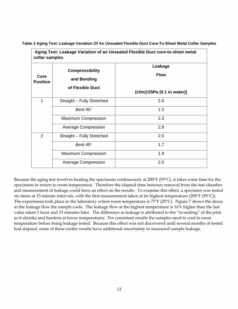
Table 3 Aging Test: Leakage Variation Of An Unsealed Flexible Duct Core-To-Sheet Metal Collar Samples
Aging Test: Leakage Variation of an Unsealed Flexible Duct core-to-sheet metal collar samples
Core Position
Compressibility
and Bending
of Flexible Duct
Leakage
Flow
(cfm@25Pa (0.1 in water))
Straight – Fully Stretched 2.6
Bent 45° 1.5
Maximum Compression 2.3
1
Average Compression 2.9
Straight – Fully Stretched 2.0
Bent 45° 1.7
Maximum Compression 1.9
2
Average Compression 2.0
Because the aging test involves heating the specimens continuously at 200°F (93°C), it takes some time for the specimens to return to room temperature. Therefore the elapsed time between removal from the test chamber and measurement of leakage could have an effect on the results. To examine this effect, a specimen was tested six times at 15-minute intervals, with the first measurement taken at its highest temperature (200°F (93°C)). The experiment took place in the laboratory where room temperature is 77°F (25°C). Figure 7 shows the decay in the leakage flow the sample cools. The leakage flow at the highest temperature is 16% higher than the last value taken 1 hour and 15 minutes later. The difference in leakage is attributed to the “re-sealing” of the joint as it shrinks and hardens at lower temperatures. For consistent results the samples need to cool to room temperature before being leakage tested. Because this effect was not discovered until several months of tested had elapsed, some of these earlier results have additional uncertainty in measured sample leakage.
12

0.230
0.240
0.250
0.260
0.270
0.280
0.290
0.300
0.310
11:10 11:25 11:40 11:55 12:10 12:25
Time (hr:min)
Leak
ge F
low
Rat
e (c
fm@
25Pa
)Sample S1105 cooling down from 200F (93°C) to room temprature 77F (25°C). Room temperature is reached before the total elapse of time shown in the figure.
Figure 7 Decay In The Measured Leakage As The Specimen Cools Down From 200F (93°C) To Room Temperature
In addition to these air leakage measurements, the visual features of the specimen failure were also documented. This included observations of drying and hardening of the adhesive, shrinking of the tape baking, delamination of the tape layers (backing/fiber/adhesive), and peeling of the tape off the medium it is applied to.
Baking Test
Figure 8 shows the baking test oven that provides constant circulating air temperature of 212°F (100°C) for the baking specimens following the UL 181B-FX “temperature test” protocol. All walls of the oven were made with 4” (100 mm) thick foil-faced foam sheathing. The bottom of the oven, sitting on the floor, was made thicker (6” (150 mm)) for added insulation. The oven was 44” (112 cm) high, 72” (183 cm) wide, and 10” (25 cm) deep. It contained four racks made of two strips of aluminum that hold the testing specimens. Six temperature sensors provided readings of the temperature profile inside the oven. Measured results show that the temperatures did not vary by more than 5°F (2.5°C) from the average temperature of 212°F (100°C). The oven had an electric heating unit controlled by a relay box to turn off at 214°F (101°C) and on at 210°F (99°C), and also protected by a safety snap thermostat rated at 250°F (121°C). The temperature values were recorded at a one-minute intervals.
13

Figure 8 High Temperature Baking Apparatus
For each duct tape (Tape 1, Tape 2, Tape 3, and Tape 4), twelve specimens were made by applying a strip of tape to three 4 by 4 inch (100 by 100 mm) samples of each of the following materials: aluminum foil, polyethylene, polyethylene terephthalate (PET), and sheet metal (galvanized steel). Another 4 by 4 inch (100 by 100 mm) control sample of each of the substrate materials is also tested without applying the tape to it. The control sample serves as a means to quantify the deterioration attributed to the substrate in isolation from the duct tape. A specimen set in the baking test, therefore consists of three similar samples and one control sample, all carried by a sheet metal tray in the oven. Figure 9 and Figure 10 demonstrates A baking specimen following the UL 181B temperature test protocol consisting of three samples of tape (Tape 3) and one control sample of the substrate (Aluminum Foil) before testing (Figure 9) and after four weeks of testing (Figure 10).
Figure 9 Before Testing
14
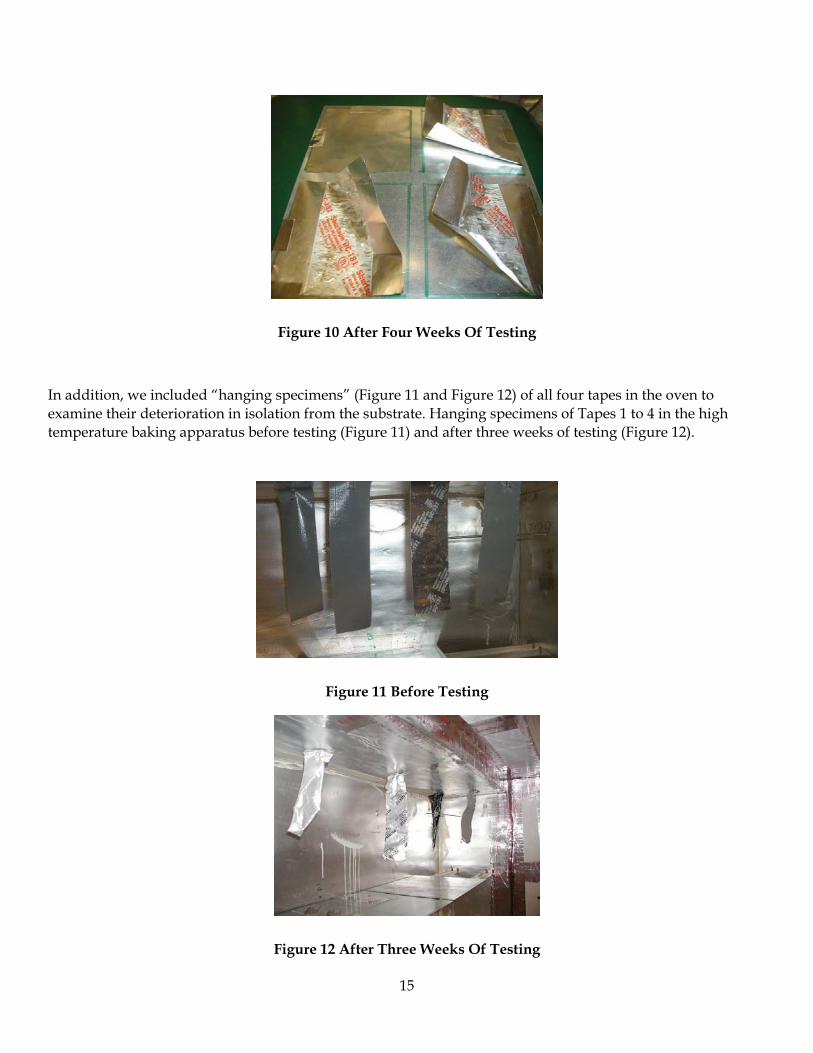
Figure 10 After Four Weeks Of Testing
In addition, we included “hanging specimens” (Figure 11 and Figure 12) of all four tapes in the oven to examine their deterioration in isolation from the substrate. Hanging specimens of Tapes 1 to 4 in the high temperature baking apparatus before testing (Figure 11) and after three weeks of testing (Figure 12).
Figure 11 Before Testing
Figure 12 After Three Weeks Of Testing
15

For the baking test, visual inspection was used as the an indicator of the tape failure. The baking test specimens were visually inspected weekly, and the durability was judged by the observed deterioration in terms of hardening, brittleness, peeling, shrinkage, wrinkling, delamination, flaking, cracking, bubbling, oozing and discoloration.
Previous Project Publications
In addition to this final report, this project has produced the following publications:
LBNL published ASTM Review drafts of sealant durability (and duct leakage) test methods.
LBNL presented a technical paper at an ASTM Sealant Symposium on durability of building sealants in Orlando, FL, January 2003: Walker, I.S. and Sherman, M.H., (2003), Sealant Longevity for Residential Ducts, Durability of Building and Construction Sealants and Adhesives, ASTM STP 1453, A. Wolf Ed., American Society for Testing and Materials, West Conshohocken, Pa. LBNL 50189.http://epb.lbl.gov/Publications/lbnl-50189.pdf
LBNL completed an interim final report “Advanced Duct Sealing” (LBNL 53547) in September 2003.http://epb.lbl.gov/Publications/lbnl-53547.pdf
LBNL gave a presentation titled “A Sticky Situation: Durability of Duct Sealants” at the PIER Research Results Seminar at the ASHRAE meeting in Anaheim, January 2004.
LBNL developed and maintained a project-use website to provide instant access to test results for CEC staff.
LBNL provided Summaries of previous testing of UL rated tapes from 1997 and 2000 to CEC staff.
LBNL prepared a Technical Report after 6 months of testing, LBNL Report 51099
16

3.0 Project Outcomes
Aging Of Core-To-Collar Samples
The core-to-collar testing took place over a total of 773 days. A combination of equipment maintenance and periodic leak testing, visual inspection and photography reduced the total number of days on the test apparatus to 695. The leakage results are shown in Figure 13 through Figure 16. The flexible duct core-to-collar specimens showed no systematic increases in leakage and no catastrophic failures. Most of the samples showed small changes in leakage (either increases or decreases) of 0.2 cfm (at 25 Pa) or less. The exception was one of the foil tape samples, which showed an increase of 0.4 cfm after the first month of testing. However, this sample then stabilized at this leakage level and did not show any significant further leakage increases. Many of the samples showed leakage reductions and our visual observations indicate that this is probably due to the flowing of the adhesive at high temperatures, such that it seals more of the small cracks and leaks as it flows. Several of the samples (10, 11, 16, 17, and 18) showed oozing of the adhesive where it ran out from the confines of the tape and was visually observed on the duct collar surfaces.
Cloth Tape 1
-0.5
-0.4
-0.3-0.2
-0.1
0
0.1
0.20.3
0.4
0.5
0 100 200 300 400 500 600 700 800
Elapsed Time, days
Chan
ge in
Air
Leak
age,
cfm S7001S7002S7003S7004S7005S7006S7007S7008
Figure 13 Two Year Testing Of Core-To-Collar Joint Specimens With Cloth Tape 1
17

Cloth Tape 2
-0.5-0.4-0.3-0.2-0.1
00.10.20.30.40.5
0 100 200 300 400 500 600 700 800
Elapsed Time, days
Cha
nge
in A
ir Le
akag
e, c
fm
S7009S7010S7011S7012
Figure 14 Two Year Testing Of Core-To-Collar Joint Specimens With Cloth Tape 2
Polypropylene (OPP) Tape 3
-0.5-0.4-0.3-0.2-0.1
00.10.20.30.40.5
0 100 200 300 400 500 600 700 800Elapsed Time, days
Chan
ge in
Air
Lea
kage
, cfm
S7013S7014S7015
Figure 15 Two Year Testing Of Core-To-Collar Joint Specimens With Polypropylene Tape 3
18

Foil Tape 4
-0.5-0.4-0.3-0.2-0.1
00.10.20.30.40.5
0 200 400 600 800
Elapsed Time, days
Cha
nge
in A
ir Le
akag
e,
cfm
S7016S7017S7018
Figure 16 Two Year Testing Of Core-To-Collar Joint Specimens With Foil Tape 4
In order to systematically record the visual deterioration of the samples, monthly pictures of all 18 specimens were taken. Typical minor deteriorations were observed as discoloration, wrinkling, and oozing, and major deteriorations were shrinking, peeling, delamination, and cracking. The observations as a result of the visual inspection are summarized in Table 4. Table 4 assigns points (0 to 2) to each of the ten categories of the degradation; “0” denoting “no sign of deterioration” in that category, “1” denoting a “moderate deterioration”, and “2” denoting an “excessive deterioration”. Like the visual inspections of the UL 181B test, these points are subjective, but they do serve to give a relative rating for each tape. The table also includes the total number of points given to each specimen. The results show that specimens S7013, S7014, and S7015 (all Tape 3, polypropylene tape) showed the most deterioration, while specimen S7009 (Tape 2, duct tape with clamping, two continuous wraps), and specimens S7017 (Tape 4, foil-butyl tape, with clamping, and one discontinuous wrap), and S7018 (Tape 4, foil-butyl tape, without clamping, and one continuous wrap) showed the least deterioration. Appendix A contains photographs illustrating the deterioration of the samples. Appendix B shows photographs of each sample before testing and at the end of the experiment.
19

20
Table 4 Summary of the Visual Inspection Results of the Flexible Duct Core-to-Sheet Metal Collar Specimens in the Aging Test
Summary of the Visual Inspection Results of the Flexible Duct Core-to-Sheet Metal Collar Specimens in the Aging Test5
Specimen Hardening
and Brittleness
Peeling Shrinkage Wrinkling Delamination Flaking Cracking Bubbling Oozing Discoloration Total Score
S7001 1 1 1 2 0 0 0 0 0 1 6S7002 1 1 1 2 0 0 0 0 0 1 6S7003 2 1 1 2 0 0 0 0 0 1 7S7004 2 1 1 2 0 0 0 0 0 1 7S7005 2 0 1 2 2 0 0 0 0 1 8S7006 2 1 2 2 2 0 0 0 0 1 10S7007 2 1 2 2 2 0 0 0 0 1 10S7008 2 1 2 2 2 0 0 0 0 1 10S7009 2 0 0 1 0 0 0 0 0 0 3S7010 2 0 0 1 0 0 0 0 1 0 4S7011 2 0 0 2 0 0 0 0 1 0 5S7012 2 0 0 2 0 0 0 0 0 1 5S7013 2 2 0 2 2 2 2 2 0 2 16S7014 2 2 0 2 2 2 2 2 0 2 16S7015 2 2 0 2 2 2 2 2 0 2 16S7016 0 0 0 2 0 0 0 0 2 0 4S7017 0 0 0 1 0 0 0 0 2 0 3S7018 0 0 0 1 0 0 0 0 2 0 3
5 “0” denotes “no sign of deterioration”, “1” denotes “moderate deterioration”, and “2” denotes “excessive deterioration”

Strap failure
One unexpected result of the core-to-collar testing was the failure of the nylon straps. The discoloration of the nylon straps observed within one month of the start of testing was an indication of thermal deterioration that later lead to total failure. Two different nylon strap materials were used and both showed the same brittle failure. The two strap types were identified by their color: beige and gray. The beige straps turned ochre with age and the gray straps turned a darker green/gray color. The nylon straps all showed the same failure mechanism due to the increased brittleness of the plastic. The failure point for most of the straps was at the point of greatest stress: where the strap passes through the ratchet. Two straps were used on each strapped sample – one at the cap end and one at the flange end. Several of the samples had their end cap and flange straps fail at different times and the failure times for each end were recorded separately. Table 5 summarizes the times of strap failure on the ten samples that used clamps.
One sample (S7014) had strap failure after four months of aging (Figure 17). Other straps lasted longer, however, all but two failed by the end of testing. The two remaining straps show the same discoloration as failed straps – but have not completely fallen off. The results show no significant pattern for flange or end caps failing first, the two straps on each sample generally failed within a couple of months of each other. Strap failure potentially is a major problem because mechanical attachment thereafter only is maintained by the duct sealant. If ducts are not well-supported, significant mechanical stress can occur to cause the sealant to fail after the clamp fails.
Figure 17Failed Plastic Strapping On One Of The Flexible Core To Sheet Metal Collar Specimens After Four Months Of Aging
Testing of the straps had not been considered part of the original experiment, so little variability in strapping materials was selected. The materials used for the straps were typical of those used in the field, which have an unknown temperature rating. Product literature from strap manufacturers (see sources in the references) show that there are other strap materials that have higher temperature ratings (e.g. Heat Stabilized Nylon 6/6 for continuous exposure above 185°F, or TEFZEL for even higher temperature
21

applications) that may also have improved high-temperature durability. As an alternative, metal straps are unlikely to fail at even higher temperature ranges.
Table 5 Failure Of Nylon Straps
Failure of nylon straps
Beige Straps Grey Straps
Days to failure Days to failure
Sample Number
Cap Flange Sample Number
Cap Flange
7001 359 119 7013 254 254
7002 401 359 7014 122 122
7003 552 756 7016 359 374
7004 359 756 7017 285 119
7009 INTACT 674
7010 756 INTACT
UL181B Revisions for Straps
In 2003 UL181B was revised to include a new test for fasteners including straps. Products that pass the test are to be marked UL 181B-C. The tests include tensile strength, smoke spread, heat production, mold growth, tension test (evaluation of the mechanical integrity of the connection), air leakage and low and high temperature aging. The most relevant test for this study is the high temperature test in which the straps are heated to 212°F (100°C) for 60 days. The straps are tested for tensile strength before and after the 60 days and must retain 75% of their initial strength. The straps are not tested at high temperature, instead they are conditioned for 48 hours at 23°C (and 50% RH) before testing at some unspecified temperature. In other words the strength at high temperature is not evaluated, instead the effect of high temperature exposure on material properties is the object of the test. Because our testing started before this new UL clamp requirement we were not able to evaluate the performance of UL listed clamps. However, this testing should be carried out in the future, particularly in light of the clamp failures we experienced and the failure of tape products in baking tests (in a previous study) that were UL listed.
While a good step forward, the new UL test falls short in being a good indicator of strap performance. The problems with the UL test are:
22

The straps are not tested in the failure mode that we observed in our testing, i.e., brittle failure in bending. Many of our observed failures were where the tie passes through the ratchet mechanism and has to bend through 90 degrees. We do not know if the strapping materials show greater or lower tensile strength as they become more brittle; many ductile materials in fact show greater tensile strength as they become brittle. In addition, the straps are not subjected to any strain during the UL high temperature baking. In real applications (and in our laboratory testing) the straps are under the influence of combined heat and strain. Without additional testing we do not know if this is a factor, but in general we would expect so.
The testing is for 60 days only. In the current study (see Table 4), none of the straps failed in 60 days. Testing straps for only 60 days appears to be insufficient.
The test wording is unclear: “Three fasteners are to be fastened around a 4 inch galvanized sleeve (mandrel) with a diameter of 4 inches (102 mm). The samples are to be installed in the intended manner and installation tools (if provided) are to be used according to the manufacturer’s instructions. The average peak tensile strength of the three samples shall not be less than 100 lb (45.5 kg). The peak tensile strength value for an individual sample shall not be less than 90 lbs (40.8 kg).” If the samples are installed around the sleeve – how is their tensile strength tested? If all three are tested at once, how can one evaluate the minimum strength of an individual fastener?
Collar-to-plenum evaluation of a new duct sealant product
Collar-to-plenum testing was performed for a new duct tape product that has been developed to have improved high temperature performance (Tape 5) as well a sample of Tape 1 as a control and for comparison purposes. The new tape was tested on the collar-to-plenum joint in order to facilitate performance comparisons with previously tested duct sealant products. The old tape (Tape 1) failed in 9 days, showing shrinkage and pulling away from the sheet metal plenum. The new tape showed substantially better durability performance failing after about 60 days. Additional tests at lower temperatures showed that the new tape takes longer to fail as temperatures are decreased, and at temperatures below (111°F) 44°C the tape takes more than 100 days to fail (we limited our test duration to 100 days). Figure 18 and Figure 19 show more detailed test results. Because they were mounted in a different location on the test apparatus, these collar-to-plenum samples were exposed to different temperatures than the core to collar samples. Table 6 shows the temperatures the specimens were exposed to during the test, and the corresponding elapsed time before failure.
23

0.000
0.500
1.000
1.500
2.000
2.500
14-M
ar
21-M
ar
28-M
ar
4-A
pr
11-A
pr
18-A
pr
25-A
pr
2-M
ay
9-M
ay
16-M
ay
23-M
ay
30-M
ay
6-Ju
n
13-J
un
20-J
un
27-J
un
4-Ju
l
11-J
ul
18-J
ul
25-J
ul
1-A
ug
Date
Leak
age
Flow
of d
uct-t
ape-
seal
ed s
peci
men
s (c
fm@
25Pa
)
S1100
S1101
S1102
S1105
Unsealed specimens before aging and baking:S1100: 7.493 cfm@25PaS1101: 8.021 cfm@25PaS1102: 7.937 cfm@25PaS1105: 8.380 cfm@25Pa
Failure
S1100, S1101, S1102, and S1105: Tape 5
Figure 18 The Measured Leakage Of The Collar-To-Plenum Joint Tape-5 Specimens
0.000
0.100
0.200
0.300
0.400
0.500
0.600
0.700
0.800
0.900
1.000
26-A
pr
27-A
pr
28-A
pr
29-A
pr
30-A
pr
1-M
ay
2-M
ay
3-M
ay
4-M
ay
5-M
ay
Date
Leak
age
Flow
of d
uct-t
ape-
seal
ed s
peci
men
s (c
fm@
25Pa
)
Unsealed specimen before aging and baking:S1103: 8.481 cfm@25Pa
S1103: Tape 1 Failure
Figure 19 Leakage Of The Collar-To-Plenum Joint Tape-1 Specimen
24

Table 6 Aging Test: Failure Results of the Collar-to-Plenum Joint Specimens
Aging Test: Failure Results of the Collar-to-Plenum Joint Specimens
Tape Specimen Temperature F (°C) Elapsed Time Before Failure
S1100 111 (44) No Failure after 4 Months and 3 Weeks
S1101 147 (64) 4 Months and 3 Weeks S1102 194 (90) 2 Months and 2 Weeks
5
S1105 194 (90) 1 Month and 3 Weeks 1 S1103 194 (90) 9 Days
Figure 20 shows the failure of the joint as the duct tape tends to pull away from the sheet metal, thus uncovering the series of overlapping fin-joints.
l
Figure 20 Exam
Baking test results: Eva
Weekly visual inspectionshowed gradual deteriorahanging specimens that wdeterioration after only tw
When the test was complinspection were recordedsimilar to Table 3, assigns“0” denoting “no sign of “moderate deterioration”includes the total number
As can be seen in Table 7deterioration, while its codeterioration at all. The T
Gap between tape and sheet meta
ple Failure Of The Collar-To-Plenum Joint For Tape 5
luating the UL 181B-FX temperature test
of the baking specimens prepared to UL181B-FX specifications tion in the specimens over the 60-day period of the test. The ere not applied to a substrate showed considerable o weeks of baking.
eted after the 60-day period, the final observations of the visual and summarized. Table 7 shows these final observations, and, points (0 to 2) to each of the ten features of the degradation;
deterioration” in that category (feature), “1” denoting a , and “2” denoting an “excessive deterioration”. The table also of points given to each specimen.
, the Tape 4 specimens (foil-butyl tape) showed the least mbination with the sheet metal substrate shows no ape 3 specimens (OPP tape) showed the most deterioration.
25

Its combination with the aluminum foil substrate was the worst case. Also, in agreement with the aging test results of the conventional duct tape (Tape 1 and Tape 2), Tape 2 showed a better performance than Tape 1. The results for the hanging specimens were consistent with those of the substrate combinations. The tapes were ranked from worst to best as follows: Tape 4; Tape 2; Tape 1; Tape 3.
All the samples except foil tape showed significant visual degradation in the baking tests and therefore they failed this test. In the future we need to find out how these tapes are able to achieve the UL listing with such obvious failures.
26

Table 7 Summary of the Visual Inspection Results of the 1-D Specimens in the Baking Test
Summary of the Visual Inspection Results of the 1-D Specimens in the Baking Test.
Specimena, b
Hardening
and
Brittleness
Peeling Shrinkage –
Substrate
Shrinkage –
Tape
Shrinkage -
Both Wrinkling Rolling Delamination Flaking Cracking Bubbling Oozing
Discolo-
ration
Total
Score
SM-Tape 1 0 1 0 1 0 2 0 1 0 0 0 0 0 5
SM-Tape 2 1 0 0 1 0 1 0 0 0 0 0 0 0 3
SM-Tape 3 0 0 0 0 0 0 0 1 1 0 0 0 1 3
SM-Tape 4 0 0 0 0 0 0 0 0 0 0 0 0 0 0
PET-Tape 1 2 0 0 1 0 1 1 1 0 0 0 0 0 6
PET-Tape 2 2 0 0 2 0 0 2 0 0 0 0 0 0 6
PET-Tape 3 1 0 0 0 0 0 2 2 2 2 2 0 1 12
PET-Tape 4 0 0 1 0 0 0 0 0 0 0 0 1 0 2
POLY-Tape 1 2 1 1 0 0 2 0 1 0 0 0 0 0 7
POLY-Tape 2 2 0 1 0 0 2 0 0 0 0 0 0 0 5
POLY-Tape 3 1 2 2 2 2 2 1 0 0 0 0 0 1 13
POLY-Tape 4 0 0 2 0 0 0 0 0 0 0 0 1 0 3
AF-Tape 1 2 2 0 2 0 1 2 2 0 0 0 0 0 11
AF-Tape 2 2 0 0 2 0 1 2 0 0 0 0 0 0 7
AF-Tape 3 2 0 0 0 0 2 2 2 2 2 2 0 2 16
AF-Tape 4 0 0 1 0 0 0 0 0 0 0 0 1 0 2
H-T –Tape 1 2 n/a n/a N/a n/a 2 1 1 0 0 0 2 0 8
H-T – Tape 2 2 n/a n/a N/a n/a 2 2 0 0 0 0 0 0 6
H-T –Tape 3 2 n/a n/a N/a n/a 2 2 0 0 2 0 0 2 10
H-T – tape 4 0 n/a n/a N/a n/a 0 1 0 0 0 0 0 0 1
a Substrate material: SM: Sheet metal; PET: Polyethylene Terephthalate, POLY: Polyethylene, and AF: Aluminum Foil b H: Tape Hanging without substrate.
27

Developing a standardized test method for evaluating duct sealant durability
The ASTM test procedure evaluates sealants using a collar-to-plenum connection as used in previous studies and for the advanced sealant testing in this study. Use of this connection places a mechanical stress on the tape sealants because they must conform to the configuration of the joint, and provides for measurable air leakage that can be used as an objective basis for determining sealant failure (unlike subjective visual inspection tests). In real applications there will be stress on duct joints including vibration or shear that might cause failure. Also, if ducts are not fully suppoted (e.g., when straps fail), the connection is likely to be under mechanical stress. The ASTM test procedure evaluates sealants using a connection that is under mechanical stress, providing an accelerated method that can in a short test-period (e.g., 60 days) identify duct sealants that are likely to fail over the useful life of a duct system when connections are under mechanical stress. In previous field research, LBNL researchers have observed collar-to-plenum connections where sealing had been attempted with cloth duct tape, and have observed many core-to-collar connections that were under mechanical stress.
Development of the ASTM standard continued during the current study, including changes to the test procedures to use heating only (earlier drafts had both heating and cooling of samples), and an increase in test temperatures. The change to heating only was made in order to make the testing simpler because cooling added significant cost and complexity to the testing. The increase in temperatures was to bring the durability testing more in-line with the existing UL181B-FX temperature test and comments received on the previous draft from ASTM ballots. Administrative tasks included preparation of drafts, preparation of supporting materials for ASTM ballots, preparing responses to comments received from the ASTM ballot process, and interactions with ASTM staff and other task group members. The ASTM Standard has completed the ASTM approval process and is now available as ASTM E2342-03 “Standard Test Method for Longevity Testing of Duct Sealant Methods.”
Discussion and Context
Using a test method similar to ASTM E2342 our previous results demonstrated that cloth-backed rubber-adhesive tapes performed substantially worse than other duct sealant methods. In contrast, the results of the current study did not demonstrate any substantial sealant failure in the configuration tested—despite the fact that the latest test was longer in duration (almost 800 days rather than about 100 days) and generally at higher temperatures.
There are several differences between the two protocols. The most substantial difference is the fact that configuration of the tested connection was different in the two protocols. The connection used in the original research and the ASTM test method is a 3-dimensional, collar-to-plenum connection, while the most recent testing used a 2-dimensional, round-to-round configuration of a core-to-collar connection. In addition the most recent testing used mechanical straps over the tapes to hold the joint together in several of the samples. This strapping helps hold the tape in place.
The impact of this difference in configuration is that the ASTM E2342 test protocol puts mechanical stress on the tape, while the most recent testing using the round-to-round configuration does not. Thus the ASTM E2342 protocol will have superior predictive power for
28

joints that experience mechanical stresses, while the round-to-round protocol would be expected to be more predictive for stress-free joints.
In 2002 the California Energy Commission (2002) conducted a rulemaking proceeding regarding whether the Title 24 Building Energy Efficiency Standards requirements, which were based on the original LBNL collar-to-plenum testing, should be changed to allow the use of cloth back rubber adhesive duct tape on the assumption that installers will follow the manufacturers installation procedures. Considerable testimony was presented indicating that installers will not consistently follow manufacturer installation procedures, and that building officials will not be able to verify if they do or not because duct connections are often inaccessible inside walls or under insulation in attics and because core-to-collar connections are covered up by flex duct liner, which is then sealed, and building officials will not take the connection apart to verify that it was correctly sealed. The Commission concluded that changing the regulations to allow cloth back rubber adhesive duct tape (by itself, not in combination with mastic) "would fail to … result in long-lasting sealing, and would fail to protect California from the potentially major energy and peak demand consequences of inadequately sealed ducts … only long-lasting duct sealing products, which are resilient to the conditions in which they are installed and installation practices that fail to meet ideal recommendations, should be allowed for use in Califonia." Previous LBNL field observations support the Commission’s findings.
Thus in the context of the typical California situation, the round-to-round, core-to-collar protocol used in the most recent testing has limited predictive power. Sealants which passed the core-to-collar test, did not pass the collar-to-plenum tests presented in earlier reports.
4.0 Conclusions and Recommendations Testing of the core-to-collar connections showed no significant failures in terms of leakage over two years of testing, but some samples showed significant visual degradation. Many of the joints became brittle during the test, which would imply that mechanical stress in almost any form could cause them to fail. Testing of the core-to-collar connection minimized mechanical stress, but in a real application there will be stress including vibration or shear that might cause failure. Also, if ducts are not fully supported (e.g., when straps fail), the connection is likely to be under mechanical stress.
For this reason test methods that include mechanical stress as part of the test will provide superior predictive power in determining sealant longevity. Both our previous test method and ASTM E2342-03 tests tapes in a condition that puts mechanical stress on the seal—by using them in a collar-to-plenum configuration. Furthermore the ASTM standard is a consensus standard that has passed the rigorous reviews required by ANSI. Thus ASTM E2342-03 is preferred over the core-to-collar testing presented in this report because it is likely to be more indicative of duct sealant performance in the field and will better safeguard California duct systems against failure in applications and conditions that are likely to occur in the field.
Another key result was that almost all the clamps used in our testing failed during the two years of testing. They all failed in the same way – becoming discolored and brittle and finally falling off the samples. For this reason we recommend either requiring metal clamps or other high temperature materials. Given that clamps are required as part of a UL181B-FX sealing system, this failure of clamps is a very important issue. It should be noted that a recent revision of UL181B includes a 60 day high temperature test for clamps, but it is not clear that this test evaluates the clamps in the failure mode that we observed.
29

The visual degradation combined with the failure of the straps means that the tested connections failed, despite the fact that there was no appreciable increase in air leakage. The significance of this failure cannot be directly inferred from our experiments because best efforts were made to minimize mechanical stresses in the tested connections. Field observation has shown that joints often have significant mechanical stresses applied to them during construction, operation, maintenance and renovation. Failed clamps will lead to mechanical stress common in the field directly acting to reduce the longevity of the duct sealant.
The benefits to California of the work in this study are:
• Retention of existing code language that restricts the use of typical duct tapes in certain applications.
• Development and approval of an ASTM standard that the Commission (and other building code authorities) can use to ensure the durability of duct sealants in California buildings.
• Development of improved duct sealants that can be used in California buildings. • Increased awareness of duct sealing issues by the California building industry.
4.1. Implications for Title 24, Part 6 Since the 2001 Building Energy Efficiency Standards were passed California requires that “Joints and seams of duct systems and their components shall not be sealed with cloth back rubber adhesive duct tapes unless such tape is used in combination with mastic and drawbands.”
The industry objected to this requirement and the Energy Commission opened a rulemaking, Docket 02-BSTD-1, to consider possible revisions to the Standards related to the issue. Potential revisions would have allowed cloth-back, rubber adhesive tapes to be used on core-to-collar connections only, which meet the installation recommendations of the ADC. As a result of that rulemaking the Energy Commission decided not to adopt any changes to the Standards. (California Energy Commission (2002))The results of this report support the Energy Commission’s decision.
Now that longevity can be evaluated using ASTM E2342-03, the current Title 24, Part 6 provisions for cloth back rubber adhesive tapes should be replaced in future versions of the Standards by a longevity requirement. Because ASTM E2342-03 creates a performance metric, we do not see the need for future versions of the Standards to call out specific classes of products as it currently does for cloth-backed rubber adhesive tapes.
When put into context of Commission findings and our previous results we recommend that: at the next appropriate standards revision cycle the following changes should be considered:
• Use of cloth back rubber adhesive tapes in Title 24 should be prohibited unless they pass an ASTM E2342 test for a test period of at least 60 days.
• Straps should be rated for continuous use at a temperature of at least 200°F. These ratings are available in manufacturers product literature and refer to UL 2043 (“Fire Test for Heat and Visible Smoke Release for Discrete Products and Their Accessories Installed in Air-Handling Spaces”) and other UL and ASTM ratings.
30

• Industry installation recommendations (e.g., ADC (2003)) should be followed. We also recommend that a new test method for determining the durability of clamping systems should be developed in order to test the actual failure modes found in the field. Such a test could be incorporated in the UL testing or be a separate ASTM (or equivalent ANSI) test method.
31

REFERENCES Air Diffusion Council (2003) “Flexible Duct Performance and Installation Standards – 4th
Edition. Air Diffusion Council, Schaumberg, IL.
ASHRAE Standard 152P, (2003) “Method of test for Determining the Design and Seasonal Efficiencies of Residential Thermal Distribution Systems”. ASHRAE, Atlanta, GA.
ASTM Standard E2342-03 (2003) “Standard Test Method for Longevity Testing of Duct Sealant Methods”. American Society for Testing and Materials, West Conshohocken, PA.
ASTM Standard E1554-03 (2003) “Standard Test Methods for Determining External Air Leakage of Air Distribution Systems by Fan Pressurization”, American Society for Testing and Materials, West Conshohocken, PA.
California Energy Commission. (2002). "Notice of Committee Conclusions, Duct Tape Rulemaking Proceeding." March 16, 2002, Sacramento, CA. California Energy Commission. http://www.energy.ca.gov/title24/ducttape/notices/2002-03-26_COM_CONCLUSIONS.PDF.
Sherman, M.H. and Walker, I.S. (2003). “Advanced Duct Sealant Testing”. CEC/LBNL Contract Report. LBNL 53547. http://epb.lbl.gov/Publications/lbnl-53547.pdf
Sherman, M.H., Walker, I.S. and Dickerhoff, D.J. (2000). “Stopping Duct Quacks: Longevity of Residential Duct Sealants”. Proc. ACEEE 2000 Summer Study. Vol. 1, pp. 273-284. American Council for an Energy Efficient Economy, Washington, D.C. LBNL 45423 http://epb.lbl.gov/Publications/lbnl-45423.pdf
Sherman, M.H. and Walker, I.S. (1998). “Can Duct Tape Take the Heat?”, Home Energy Magazine, Vol. 14, No. 4, pp.14-19, July/August 1998, Berkeley, CA. LBNL 41434. http://epb.lbl.gov/Publications/lbl-41434.pdf
Underwriters Laboratory (UL). (1993). Standard for Closure Systems for Use with Rigid Air Ducts and Air Connectors – UL 181A. Underwriters Laboratories Inc. Northbrook, IL.
Underwriters Laboratory (UL). (2003). Standard for Closure Systems for Use with Flexible Air Ducts and Air Connectors – UL 181B. Underwriters Laboratories Inc. Northbrook, IL.
Walker, I.S. and Sherman, M.H., (2003), Sealant Longevity for Residential Ducts, Durability of Building and Construction Sealants and Adhesives, ASTM STP 1453, A. Wolf Ed., American Society for Testing and Materials, West Conshohocken, Pa. LBNL 50189. http://epb.lbl.gov/Publications/lbnl-50189.pdf
Walker, I., Sherman, M., Modera, M., and Siegel, J. (1998). Leakage Diagnostics, Sealant Longevity, Sizing and Technology Transfer in Residential Thermal Distribution Systems. LBNL-41118, Lawrence Berkeley National Laboratory, Berkeley, CA. http://epb.lbl.gov/Publications/lbl-41118.pdf
Walker , I.S., and Sherman, M.H. (2000). “Assessing the Longevity of Residential Duct Sealants”, Proc. RILEM 3rd International Symposium: Durability of Building and
32

Construction Sealants, February 2000. pp. 71-86. RILEM Publications, Paris, France. LBNL 43381. http://epb.lbl.gov/Publications/lbnl-43381.pdf
Example sources for high temperature cable-tie/clamp information:
http://www.nelcoproducts.com/
http://www.planetcableties.com/download_catalog.shtml
33

APPENDIX A: EXAMPLES OF VISUAL DETERIORATION
A

Appendix A. Examples of visual deterioration
Adhesive on inner tape layer Adhesive on inner tape layer
Figure A1. Sample 1. This figure shows the curling of the tape end where it is no longer stuck to the inner layer of tape. The yellow (circled) areas show where the adhesive has remained on the inner tape layer. The tape edges have curled away from the duct and the tape surface is wrinkled. The indentations in the center of the tape shows where the strap used to be before it fell off.
A-1

Figure A2. Sample 1. The second seal still has part of the nylon clamp in place. This shows the same characteristics as in Figure A1.
A-2

Wrinkling
Figurfrom
Delamination
e A3. Sample 1. The tape shows wrinkling and delamination of the reinforcing mesh the tape backing.
A-3

Figure A4. Sample 3. Tape has separated from the flex duct core
A-4
Separation
at the tape edges

Adhesive remains
Reinforcing Mesh
Figure A5. Sample 5. The end of the tape shows shrinkage and delamination. Compare this to Figure A1, where the presence of the clamp in A1 reduces the shrinkage and delamination at the center of the tape. This figure clearly shows the adhesive left where the tape was originally attached and the reinforcing mesh separated from the backing.
A-5

Adhesive Remains
Original tape end location
Figure A6. Sample 6. This figure is similar to Figure A5, but shows even more shrinkage.
A-6

Figure A7. Sample 7. Like sample 6, sample 7 shows considerable shrinkage and delamination.
A-7

Figure A8. Sample 7. The edges of the tape have lifted off the duct surface in large wrinkles.
A-8

Figure A9. Sample 8. The edges of the tape are no longer stuck to the flex duct core.
A-9
Figure A10. Sample 9. The clamp shows its brittle failure. Note that these clamp sections are now held in place because they are stuck to the duct tape.
A-10

Figure A11. Sample 9. This sample shows almost no shrinkage or delamaination.
A-11

Figure A12. Sample 10. The adhesive has oozed out onto the surface of the duct.
A-12

Figure A13. Sample 11. The adhesive has oozed out the edge of the tape.
A-13

Figure A14. Sample 12. The end of the tape has wrinkled and shrunk.
A-14

Figure A15. Sample 13. This sample shows cracking and disintegration of the tape
A-15

Figure A16. Sample 13. This sample is cracking and peeling.
A-16

Figure A17. Sample 14. This sample shows the same cracking and splitting as Sample 13.
A-17

Figure A18. Sample 15. Like samples 13 and 14, this sample is also peeling and cracking. This figure shows how the metallized layer is splitting from the adhesive layer.
A-18

Figure A19. Sample 16. This sample shows oozing of the adhesive at the tape edges.
A-19

Oozing adhesive
Clamp remains
No end shrinkage or peeling
Figure A20. Sample 17. As with sample 16, this metal foil tape is showing oozing of the adhesive. Note that there is no shrinkage or delamination like the other tapes at the end of the tape. There is also a small piece of clamp stuck in place by the oozed adhesive.
A-20

APPENDIX B: INITIAL AND FINAL PHOTOGRAPHS OF TEST SAMPLES
B

Appendix B. Initial and Final photographs of test samples
Sample 1
B-1
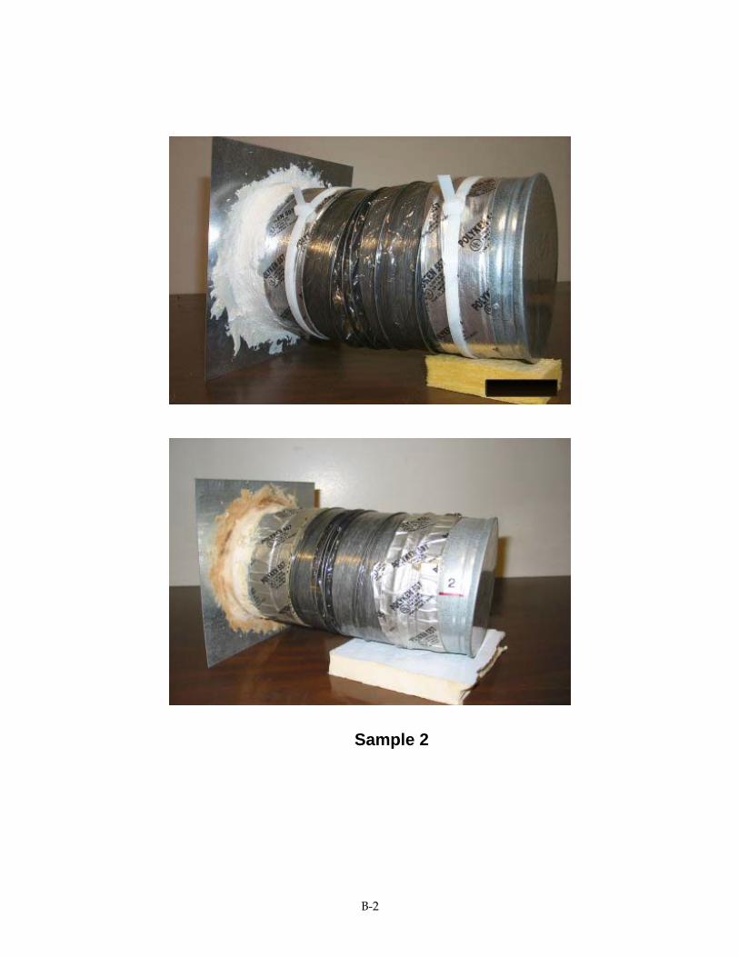
Sample 2
B-2

Sample 3
B-3

Sample 4
B-4

Sample 5
B-5

Sample 6
B-6

Sample 7
B-7

Sample 8
B-8

Sample 9
B-9

Sample 10
B-10

Sample 11
B-11

Sample 12
B-12

Sample 13
B-13

Sample 14
B-14

Sample 15
B-15

Sample 16
B-16

Sample 17
B-17

Sample 18
B-18

APPENDIX C: NOTICE OF COMMITTEE CONCLUSIONS
C

STATE OF CALIFORNIA – THE RESOURCES AGENCY GRAY DAVIS, Governor
D
BI(a(drrininpSpcthesImrrdcow EOpta(wwwss
CALIFORNIA ENERGY COMMISSION1516 NINTH STREET SACRAMENTO, CA 95814-5512
UCT TAPE RULEMAKING PROCEEDING Docket 02-BSTD-1
March 26, 2002
ACKGROUND n response to a petition filed by Tyco Adhesives and Shurtape Technologies, Inc. Tyco), the Commission opened a rulemaking proceeding to consider possible repeal or mendment of requirements in the California Code of Regulations, Title 24, Part 6 Building Energy Efficiency Standards) that allow the use of cloth back rubber adhesive uct tape for sealing ducts only if installed in combination with mastic. The current equirements were adopted by emergency pursuant to AB 970 in January, 2001. The egulations were subsequently readopted and made permanent in April, 2001. They went to effect for nonresidential buildings and some residences on June 1, 2001. They went to effect for the remaining residential buildings on January 1, 2002. In granting the
etition, the Commission took no position on the substantive merits of Tyco's petition. ince the mid-1990s the Commission has recognized the severe energy and peak demand roblems caused by badly designed, sealed and installed heating, ventilation and air onditioning (HVAC) system ducts. In 1998 the Commission took a first step to address ese problems in its performance standards by giving compliance credit for duct
fficiency improvement, in particular for pressure-tested and field verified ducts that are ealed using long-lasting sealant products. n 2000 the Legislature enacted AB 970, requiring the Commission to adopt new easures in the building energy efficiency standards to reduce peak electric load to
espond to the State's electricity crisis. The Commission adopted several new equirements, among them are requirements that do not allow cloth-back rubber adhesive uct tape for the connecting of joints in HVAC system ducts unless such tape is used in ombination with mastic. These are the requirements that Tyco has petitioned to repeal r amend, so that cloth back rubber adhesive duct tape alone can be used on duct joints, ithout the use of mastic
XPRESS TERMS AND COMMITTEE HEARING n February 22, 2002 the Commission opened a rulemaking proceeding to consider ossible repeal or amendment of the requirements for cloth back rubber adhesive duct pe. To start the rulemaking the Commission released for consideration Express Terms
45 Day Language) to respond to concerns expressed by Tyco. The Express Terms ould amend the requirements to allow the use of cloth back rubber adhesive duct tape ithout mastic for a limited time (until January 1, 2004) on only those duct connections here manufacturers recommend (on flex duct to fitting joints) in strict compliance with
pecific installation procedures. This allowance would only apply to field-fabricated duct ystems in low-rise residential buildings.
1

The Commission stated the following in its Initial Statement of Reasons: The Express Terms result from a specific proposal in a petition for rulemaking. One alternative is to not adopt the Express Terms. Other alternatives to the Express Terms may be proposed by participants in the rulemaking proceeding. At this point the Commission has not rejected alternatives to the Express Terms. The Energy Efficiency Committee held a hearing on March 21, 2002 to receive public comment on the Express Terms. SUMMARY OF KEY COMMENTS The following is a summary of the key comments that the Committee heard at the March 21, 2002 hearing. California Building Officials (CALBO) opposes any changes to the Standards at this time. A major effort has been made to get building officials (approximately 550 jurisdictions statewide) and the building industry trained on the new Standards. There is no reason to change. The industry has already moved away from cloth tape or is in the process of doing so. The current options for compliance are fully satisfactory. The duct tape requirements are one of the easiest aspects of the Standards to enforce. Making a change to the Standards at this time would be very disruptive and would reduce the credibility of the Standards. California Building Industry Association (CBIA) agrees with CALBO. Making a change to the current duct tape requirements undercuts a CBIA effort that has been going on since 1998 to train the largest California builders in how to do a good job of sealing ducts using long-lasting duct sealing materials. There is no problem with the industry being able to comply with the current Standards. If a more rigorous installation process was required to make it possible to use cloth back rubber adhesive duct tape in limited applications, builders would likely choose to use other sealing alternatives. Insulation Contractors Association (ICA) supports CALBO’s position. Insulation contractors get callbacks from customers not seeing an impact in their energy bills after an insulation upgrade. Often the problem turns out to be bad duct sealing. Bad duct sealing costs insulation contractors money. If the Commission’s goal is to get high performance duct tape into the California market, then the way to do that is to keep the Standards the way they are. Tyco and Shurtape support Commission adoption of the Express Terms. They agree with other stakeholders that the Express Terms should be improved to include other specific installation requirements for cloth back rubber adhesive duct tape. They will put installation instructions in shipping boxes for duct tape, will put an abbreviated set of instructions in the liner of the core of the tape roll, and will put a marking agreed to with the Commission, which says this tape is prohibited from use on other than flex duct to fitting joints, at intervals on the tape backing. They will work with the Commission to train building officials and contractors about installation practices that are acceptable to
2

the Commission. They will work with the Commission and LBNL to develop a new test procedure that will insure that future duct tape products will last for the life of the home, accounting for hot temperatures and dirty conditions in California attics where ducts are installed. Rottiers Sales Associates (Northern California distributor of Tyco products) are continuing to supply cloth back rubber adhesive duct tape to areas of Northern California outside of the Sacramento area where building officials are not enforcing the 2001 Standards requirement. Proctor Engineering (California air conditioning systems expert and field researcher) urges the Commission to not allow the use of cloth back rubber adhesive duct tape. Sealing ducts is a very important energy savings and peak demand reduction action. Once construction of a house is finished, the joints where ducts leak are often inaccessible inside walls or under insulation in attics. If the joint fails, it will stay failed for the life of the house, wasting energy and the homeowner’s or renter’s money the whole time. He presented survey data that shows that a significant portion of contractors fail to follow manufacturer’s installation instructions. He believes this can’t be changed by a revision to the Standards. Installation instructions similar to the Express Terms currently are included in flex duct shipping boxes, but they don’t get followed consistently. If the Commission wants to allow cloth tape, several key points would need to be added to the Express Terms to make the installation instructions acceptable. Pacific Gas and Electric Company (PG&E) recommends that the Commission not change the Standards. Failed duct sealing means higher energy bills for their customers. Their programs have not allowed cloth tape since 1998. PG&E thinks that the installation instructions that are supplied with flex ducts are a good idea, but since they are printed on a small piece of paper in very small type, they could easily be disregarded by installers. If the Commission wanted to allow cloth tape, several points would need to be added to make the installation instructions in the Express Terms satisfactory. They think that rigorous installation instructions that are rigorously enforced would discourage the use of cloth tape. They agree that the use of cloth tape should be prohibited for collar to plenum joints. Lawrence Berkeley National Laboratory (LBNL) recommends to not allow the use of cloth tape on collar to plenum joints and not allow the use of cloth tape if industry installation recommendations are not consistently followed. Their past testing shows that cloth back rubber adhesive duct tape is not a long-lasting duct sealing product. They recently have begun additional testing of duct tape on flex duct to collar joints. There are early signs of degradation of a sample, which was not installed to meet manufacturer’s installation instructions. C. A. Shroeder, Inc. (CASCO - factory-fabricated flex duct manufacturer) said that a building official cannot tell whether the flex duct to fitting joint is properly installed because it is covered up by the flex duct liner, which is then sealed. The building official will not take the joint apart to see if was correctly installed.
3

Underwriters Laboratories (UL) was not aware of a problem with cloth back rubber adhesive duct tape prior to the Commission’s actions. UL does not have the resources to keep track of research, such as that in the building science literature over the past several years regarding the failure of duct tape. UL has limited ability to make changes to its requirements on its own authority. UL primarily gets its advice from manufacturers, but it is open to other input so long as it is submitted in a formal way following UL procedures. UL requires flex duct manufacturers to put installation requirements for sealing the flex duct to fitting joint in packing boxes. UL only endorses the use of duct tape on the flex duct to fitting joint when the installation is fully compliant with these instructions. UL has no mechanism to address problems with using duct tape on other duct system joints or failure of installers to follow the installation instructions. UL has not considered the possibility of requiring duct tape to be more durable so as to withstand installation problems that occur in the field. Intertape Polymer Group (duct tape manufacturer) in a letter submitted to the Commission after the hearing urged the Commission not to adopt changes to the 2001 Standards. The letter stated, “… the CEC would be remiss in allowing duct tape to be continued to be used on an application that would waste energy and millions of dollars paid for that energy … the pressure sensitive tape industry has come up with a solution to this problem, that is the UL 181 B-FX polypropylene backed tape with acrylic adhesive … and the fact that this product already exists in the marketplace [indicates] there is no hardship created by enforcing this change.” COMMITTEE FINDINGS Based on the comment received at the March 21, 2002 hearing and documents submitted to the docket, the Energy Efficiency Committee finds that adoption of the Express Terms is unnecessary and would be disruptive to the effective implementation of the 2001 Building Energy Efficiency Standards. The Express Terms would fail to insure that sealing duct systems with cloth back rubber adhesive duct tape would result in long-lasting sealing, and would fail to protect California from the potentially major energy and peak demand consequences of inadequately sealed ducts. The Committee believes that only long-lasting duct sealing products, which are resilient to the conditions in which they are installed and installation practices that fail to meet ideal recommendations, should be allowed for use in California. The Committee also is concerned with the admission of a Tyco business associate who knowingly has continued to supply cloth back rubber adhesive duct tape for installations that would not be in compliance with the 2001 Building Energy Efficiency Standards.
4

COMMITTEE RECOMMENDATION The Energy Efficiency Committee recommends that the Commission not adopt the Express Terms or any other changes to the Building Energy Efficiency Standards in response to the Tyco petition. Signed:
5


