DUCA-LCD96 - ducatienergia.com€¦ · Chapter 3 10 DUCA-LCD96 NETWORK ANALYSER Rev. 1.1 TECHNICAL...
84
NETWORK ANALYSER EN Assembly and use instructions DUCA-LCD96 468001289 DUCA-LCD96 485 468001291 DUCA-LCD96-ETH 468001296 DUCA-LCD96-PROFI 468001294 DUCA-LCD96 485-RELE 468001293 DUCA-LCD96 485-IO 468001292 DUCA-LCD96 BASE 468001288 energia DUCA-LCD96
Transcript of DUCA-LCD96 - ducatienergia.com€¦ · Chapter 3 10 DUCA-LCD96 NETWORK ANALYSER Rev. 1.1 TECHNICAL...
NETWORK ANALYSEREN Assembly and use instructions
DUCA-LCD96468001289DUCA-LCD96 485468001291DUCA-LCD96-ETH468001296 DUCA-LCD96-PROFI468001294DUCA-LCD96 485-RELE468001293DUCA-LCD96 485-IO468001292DUCA-LCD96 BASE468001288
energia
DU
CA
-LC
D96


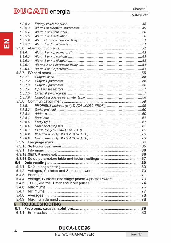
SUMMARY
DUCA-LCD96 3Rev. 1.1 NETWORK ANALYSER
Chapter 1
EN
energia
1 GENERAL INFORMATION1.1 Reference regulations and conformity....................................................51.2 Use and storage of the manual ................................................................61.2.1 Storing .....................................................................................................61.2.2 Copyright..................................................................................................6
1.3 General safety warnings ...........................................................................72 PACKAGING CONTENTS2.1 Removal of packaging ..............................................................................82.2 Description of the contents ......................................................................9
3 TECHNICAL CHARACTERISTICS3.1 Description of the device........................................................................103.2 Measuring functions ...............................................................................103.3 Models ......................................................................................................113.4 Overall dimensions .................................................................................123.5 Technical data ..........................................................................................13
4 INSTALLATION4.1 Assembly .................................................................................................184.2 Disassembly ............................................................................................194.3 Connections .............................................................................................204.3.1 Inputs connections .................................................................................224.3.2 Optional outputs connections.................................................................244.4 Configurationsforfirstuse ....................................................................26
5 OPERATING5.1 Front panel ...............................................................................................275.2 Use of device ...........................................................................................295.2.1 Access to the page ................................................................................305.3 ConfigurationoftheSETUPdevice .......................................................315.3.1 Control keys ...........................................................................................32
5.3.1.1 Data entry .....................................................................................................335.3.2 Password menu .....................................................................................34
5.3.2.1 Password creation ........................................................................................345.3.2.2 Passwordmodification ..................................................................................355.3.2.3 Password entry .............................................................................................35
5.3.3 Reset menu............................................................................................375.3.4 Configurationmenu................................................................................38
5.3.4.1 Type of entry .................................................................................................385.3.4.2 Set CT ratio ..................................................................................................405.3.4.3 Set VT ratio ...................................................................................................415.3.4.4 Average time ................................................................................................425.3.4.5 Current threshold for T2 hour counter ..........................................................425.3.4.7 Generation ....................................................................................................445.3.4.8 Euro/energy factor ........................................................................................455.3.4.9 CO2/energy factor ........................................................................................455.3.4.10 Back lighting .................................................................................................465.3.4.11 Energy saving ...............................................................................................46
5.3.5 Digital output menu ................................................................................475.3.5.1 Digital output mode .......................................................................................47
Chapter 1
4 DUCA-LCD96NETWORK ANALYSER Rev. 1.1
SUMMARY
ENenergia
5.3.5.2 Energy value for pulse ..................................................................................485.3.5.3 Alarm1 or alarm2(*) parameter .....................................................................495.3.5.4 Alarm 1 or 2 threshold ..................................................................................505.3.5.5 Alarm 1 or 2 activation ..................................................................................505.3.5.6 Alarms 1 or 2 activation delay ......................................................................515.3.5.7 Alarm 1 or 2 hysteresis .................................................................................51
5.3.6 Alarm output menu.................................................................................525.3.6.1 Alarm 3 or 4 parameter (*) ............................................................................525.3.6.2 Alarm 3 or 4 threshold ..................................................................................535.3.6.3 Alarm 3 or 4 activation ..................................................................................535.3.6.4 Alarms 3 or 4 activation delay ......................................................................545.3.6.5 Alarm 3 or 4 hysteresis .................................................................................54
5.3.7 I/O card menu ........................................................................................555.3.7.1 Outputs span ................................................................................................555.3.7.2 Output 1 parameter ......................................................................................565.3.7.3 Output 2 parameter ......................................................................................565.3.7.4 Input pulses factors ......................................................................................575.3.7.5 External synchronism ...................................................................................575.3.7.6 Output associated parameter table ..............................................................58
5.3.8 Communication menu ............................................................................595.3.8.1 PROFIBUS address (only DUCA-LCD96-PROFI) ........................................595.3.8.2 Serial protocol ...............................................................................................605.3.8.3 Address ........................................................................................................605.3.8.4 Baud rate ......................................................................................................615.3.8.5 Parity type .....................................................................................................615.3.8.6 Number of stop bits ......................................................................................625.3.8.7 DHCP (only DUCA-LCD96 ETH) ..................................................................625.3.8.8 IP Address (only DUCA-LCD96 ETH) .........................................................635.3.8.9 Host name (only DUCA-LCD96 ETH) ..........................................................63
5.3.9 Language menu .....................................................................................645.3.10 Self-diagnosis menu ..............................................................................655.3.11 Info menu ...............................................................................................665.3.12 SETUP mode exit ..................................................................................665.3.13 Setup parameters table and factory settings .........................................67
5.4 Data reading.............................................................................................695.4.1 Default page setting ...............................................................................695.4.2 Voltages, Currents and 3-phase powers ................................................705.4.3 Energies .................................................................................................715.4.4 Voltage, Currents and single phase 3-phase Powers ............................735.4.5 THDF, Alarms, Timer and input pulses...................................................745.4.6 Maximums..............................................................................................765.4.7 Minimums...............................................................................................775.4.8 Averages ................................................................................................785.4.9 Maximum demand .................................................................................78
6 TROUBLESHOOTING6.1 Problems, causes, solutions ..................................................................796.1.1 Error codes ...........................................................................................80
GENERAL INFORMATION
DUCA-LCD96 5Rev. 1.1 NETWORK ANALYSER
Chapter 1
EN
energia
1 GENERAL INFORMATION
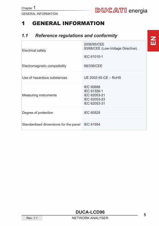
1.1 Reference regulations and conformity
Electrical safety
2006/95/CEE93/68/CEE (Low-Voltage Directive).
IEC 61010-1
Electromagnetic compatibility 89/336/CEE
Use of hazardous substances UE 2002-95-CE – RoHS
Measuring instruments
IEC 60688IEC 61326-1IEC 62053-21IEC 62053-23IEC 62053-31
Degree of protection IEC 60529
Standardised dimensions for the panel IEC 61554

Chapter 1
6 DUCA-LCD96NETWORK ANALYSER Rev. 1.1
GENERAL INFORMATION
ENenergia
1.2 Use and storage of the manual
Carefully read this manual and adhere to the indications described prior to using the device.
This manual contains all of the safety information, the technical aspects and the operating necessary to ensure the correct use of the device and maintain it in safe conditions.
1.2.1 Storing The manual must be stored close to the device; safe from liquids and anything else which may compromise its leggibility.The manual and the declaration of conformity are both an integral part of the device until it is dismantled.If the manual is lost or illegible please request a copy from the manufacturer.
1.2.2 CopyrightThe copyright of this manual is the property of DUCATI Energia S.p.A.This manual contains texts, designs and illustrations of a technical nature which must not be disclosed or transmitted to third parties, even partially, without the written authorisation of DUCATI Energia S.p.A.
GENERAL INFORMATION
DUCA-LCD96 7Rev. 1.1 NETWORK ANALYSER
Chapter 1
EN
energia
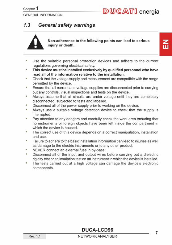
1.3 General safety warnings
Non-adherence to the following points can lead to serious injury or death.
• Use the suitable personal protection devices and adhere to the current regulations governing electrical safety.
• Thisdevicemustbeinstalledexclusivelybyqualifiedpersonnelwhohaveread all of the information relative to the installation.
• Check that the voltage supply and measurement are compatible with the range permitted by the device.
• Ensure that all current and voltage supplies are disconnected prior to carrying out any controls, visual inspections and tests on the device.
• Always assume that all circuits are under voltage until they are completely disconnected, subjected to tests and labelled.
• Disconnect all of the power supply prior to working on the device. • Always use a suitable voltage detection device to check that the supply is
interrupted. • Pay attention to any dangers and carefully check the work area ensuring that
no instruments or foreign objects have been left inside the compartment in which the device is housed.
• The correct use of this device depends on a correct manipulation, installation and use.
• Failure to adhere to the basic installation information can lead to injuries as well as damage to the electric instruments or to any other product.
• NEVER connect an external fuse in by-pass. • Disconnect all of the input and output wires before carrying out a dielectric
rigidity test or an insulation test on an instrument in which the device is installed. • The tests carried out at a high voltage can damage the device's electronic
components.

Chapter 2
8 DUCA-LCD96NETWORK ANALYSER Rev. 1.1
PACKAGING CONTENTS
ENenergia
2 PACKAGING CONTENTS
2.1 Removal of packaging
We recommend that the packaging is stored in a suitable location in compliance with the warranty terms
PACKAGING CONTENTS
DUCA-LCD96 9Rev. 1.1 NETWORK ANALYSER
Chapter 2
EN
energia
D U C A T I e n e r g i a s . p . a .
40132 BOLOGNA - Via M.E.Lepido, 182 - C.P. 3159 Bo Ponente - Tel. 051/404140 - Telefax: 402040
C E R T I F I C A T O D I C O L L A U D O / T E S T R E P O R T
DUCA-LCD96 4854 6 8 . 0 0 . 1 2 9 1
S e r i a l N u m b e r : … … … … … … … … … … … … … … … … …
Calibration System: …………………………………………………………………………
Certified by:…………………………………………………………………………………..
ParameterRated values
Measured values Error percentage at full scale.
…. V rms
V rms
%
V1
…. V rms
V rms
%
…. V rms
V rms
%
V2
…. V rms
V rms
%
…. V rms
V rms
%
V3
…. V rms
V rms
%
…. A rms
A rms
%
I1
…. A rms
A rms
%
…. A rms
A rms
%
I2
…. A rms
A rms
%
…. A rms
A rms
%
I3
…. A rms
A rms
%
Firmware vers ion:………………………………………………………………
Accuracy c lass : ±0.5% at fu l l sca le (±1 d ig i t ) a t 20°C
D a t e : … … … … … … … … … … … … … … … … … … … … … … … … … … …
C h e c k e r : … … … … … … … … … … … … … … … … … … … … … … … … … … …
energia
energiaenergia
1 2
5
3
4
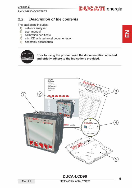
2.2 Description of the contentsThe packaging includes:
1) network analyser2) user manual3) calibrationcertificate4) mini CD with technical documentation5) assembly accessories
Prior to using the product read the documentation attached and strictly adhere to the indications provided.
Chapter 3
10 DUCA-LCD96NETWORK ANALYSER Rev. 1.1
TECHNICAL CHARACTERISTICS
ENenergia
3 TECHNICAL CHARACTERISTICS
3.1 Description of the deviceThe DUCA-LCD96 network analyser is an instrument that measures of the main electric quantities on 3-phase and monophase networks designed for the monitoring and the local or remote analysis of:
• electrical parameters of systems in low or medium voltage; • system energy consumption.
3.2 Measuring functionsAll of the DUCA-LCD96 series models are able to measure and process the quantities shown below.
1) Voltages (phase neutral and linked) and relative peak values;2) Currents and relative peak values;3) Active, reactive and apparent phase powers and the 3-phase system on 2 and
4 quadrants;4) Power factors or PF phases and the 3-phase system, with distinction icon
between the inductive and capacitive load;5) Frequency (measured on L1-N phase);6) Active, reactive and apparent phase energies and the 3-phase system on 2
quadrants (with automatic recognition function of the AT directions);7) Active, reactive and apparent power phases and the 3-phase system on 4
quadrants (monitoring of energy absorbed and generated by the system);8) Average power values on a time period programmed by the user;9) Maximum calculated demand on active and apparent power;10) Voltage and current THdF expressed in absolute and percent values;11) T1 increase total operating hour counter and T2 decrease partial hour counter;12) Balance of active, reactive and apparent energy of 3-phase system,
balance = absorbed energy - generated energy;13) Balance of the "partial" active, reactive and apparent energies of the 3-phase
system on 4 quadrants in a period that can be programmed by the user, balance = energy absorbed - energy generated;
The change frequency (for each quantity available on display) is equal to 2 times/second.
TECHNICAL CHARACTERISTICS
DUCA-LCD96 11Rev. 1.1 NETWORK ANALYSER
Chapter 3
EN
energia
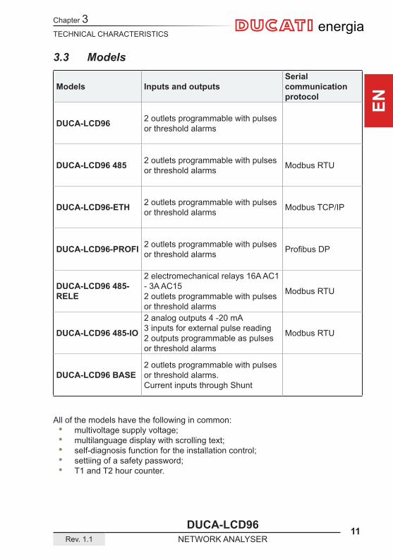
3.3 Models
Models Inputs and outputsSerial communication protocol
DUCA-LCD96 2 outlets programmable with pulses or threshold alarms
DUCA-LCD96 485 2 outlets programmable with pulses or threshold alarms Modbus RTU
DUCA-LCD96-ETH 2 outlets programmable with pulses or threshold alarms Modbus TCP/IP
DUCA-LCD96-PROFI 2 outlets programmable with pulses or threshold alarms ProfibusDP
DUCA-LCD96 485-RELE
2 electromechanical relays 16A AC1 - 3A AC15 2 outlets programmable with pulses or threshold alarms
Modbus RTU
DUCA-LCD96 485-IO
2 analog outputs 4 -20 mA 3 inputs for external pulse reading 2 outputs programmable as pulses or threshold alarms
Modbus RTU
DUCA-LCD96 BASE2 outlets programmable with pulses or threshold alarms. Current inputs through Shunt
All of the models have the following in common: • multivoltage supply voltage; • multilanguage display with scrolling text; • self-diagnosis function for the installation control; • settiing of a safety password; • T1 and T2 hour counter.
Chapter 3
12 DUCA-LCD96NETWORK ANALYSER Rev. 1.1
TECHNICAL CHARACTERISTICS
ENenergia
A
B C
ED
F
e n e r g i aDUCA-LCD96
VIP E L MIXMAX
MINAVG
OKSETUP
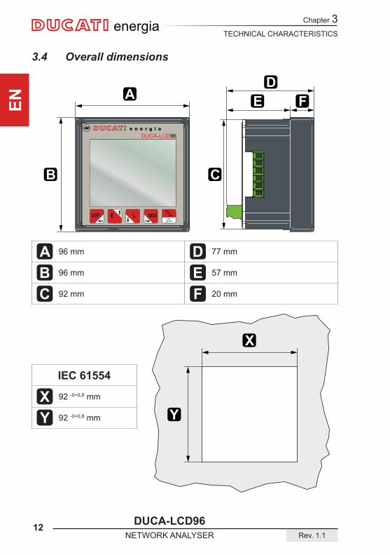
A 96 mm D 77 mm
B 96 mm E 57 mm
C 92 mm F 20 mm
IEC 61554
X 92 -0+0,8 mm
Y 92 -0+0,8 mm
X
Y
3.4 Overall dimensions
TECHNICAL CHARACTERISTICS
DUCA-LCD96 13Rev. 1.1 NETWORK ANALYSER
Chapter 3
EN
energia
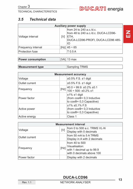
3.5 Technical dataAuxiliary power supply
Voltage interval [V]
from 24 to 240 a.c./d.c.from 48 to 240 a.c./d.c. DUCA-LCD96-ETH,DUCA-LCD96-PROFI, DUCA-LCD96 485-IO
Frequency interval [Hz] 45 ÷ 65Protection fuse T 0.5 A
Power consumption [VA] 13 max
Measurement type Sampling TRMS
Measurement accuracyVoltage ±0.5% F.S. ±1 digitOutlet current ±0.5% F.S. ±1 digit
Frequency [Hz] 40.0 ÷ 99.9: ±0.2% ±0.1100 ÷ 500: ±0.2% ±1
Power factor±1% ±1 digit(fromcosΦ=0,3Inductive tocosΦ=0,3Capacitive)
Active power±1% ±0,1% F.S(fromcosΦ=0,3Inductive tocosΦ=0,3Capacitive)
Active energy Class 1
Measurement interval
Voltage [V] from 0 to 500 a.c. TRMS VL-NDisplay with 0 decimals
Outlet current from 50 mA to 5 A TRMSDisplay in A with 2 decimals
Frequency [Hz]
from 40 to 500Visualisation:with 1 decimal up to 99.9with 0 decimals above 100
Power factor Display with 2 decimals
Chapter 3
14 DUCA-LCD96NETWORK ANALYSER Rev. 1.1
TECHNICAL CHARACTERISTICS
ENenergia
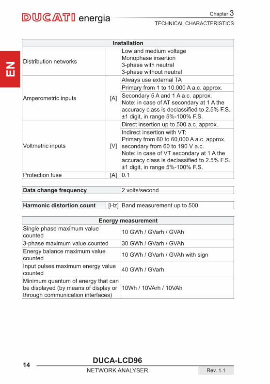
Installation
Distribution networks
Low and medium voltageMonophase insertion3-phase with neutral3-phase without neutral
Amperometric inputs [A]
Always use external TAPrimary from 1 to 10.000 A a.c. approx.Secondary 5 A and 1 A a.c. approx.Note: in case of AT secondary at 1 A the accuracyclassisdeclassifiedto2.5%F.S.±1 digit, in range 5%-100% F.S.
Voltmetric inputs [V]
Direct insertion up to 500 a.c. approx.Indirect insertion with VT:Primary from 60 to 60,000 A a.c. approx.secondary from 60 to 190 V a.c.Note: in case of VT secondary at 1 A the accuracyclassisdeclassifiedto2.5%F.S.±1 digit, in range 5%-100% F.S.
Protection fuse [A] 0.1
Data change frequency 2 volts/second
Harmonic distortion count [Hz] Band measurement up to 500
Energy measurementSingle phase maximum value counted 10 GWh / GVarh / GVAh
3-phase maximum value counted 30 GWh / GVarh / GVAhEnergy balance maximum value counted 10 GWh / GVarh / GVAh with sign
Input pulses maximum energy value counted 40 GWh / GVarh
Minimum quantum of energy that can be displayed (by means of display or through communication interfaces)
10Wh / 10VArh / 10VAh
TECHNICAL CHARACTERISTICS
DUCA-LCD96 15Rev. 1.1 NETWORK ANALYSER
Chapter 3
EN
energia
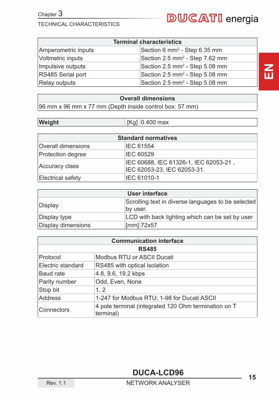
Terminal characteristicsAmperometric inputs Section 6 mm2 - Step 6.35 mmVoltmetric inputs Section 2.5 mm2 - Step 7.62 mmImpulsive outputs Section 2.5 mm2 - Step 5.08 mmRS485 Serial port Section 2.5 mm2 - Step 5.08 mmRelay outputs Section 2.5 mm2 - Step 5.08 mm
Overall dimensions96 mm x 96 mm x 77 mm (Depth inside control box: 57 mm)
Weight [Kg] 0.400 max
Standard normativesOverall dimensions IEC 61554Protection degree IEC 60529
Accuracy class IEC 60688, IEC 61326-1, IEC 62053-21 , IEC 62053-23, IEC 62053-31.
Electrical safety IEC 61010-1
User interface
Display Scrolling text in diverse languages to be selected by user.
Display type LCD with back lighting which can be set by userDisplay dimensions [mm] 72x57
Communication interfaceRS485
Protocol Modbus RTU or ASCII DucatiElectric standard RS485 with optical isolationBaud rate 4.8, 9.6, 19.2 kbpsParity number Odd, Even, NoneStop bit 1, 2Address 1-247 for Modbus RTU; 1-98 for Ducati ASCII
Connectors 4 pole terminal (integrated 120 Ohm termination on T terminal)
Chapter 3
16 DUCA-LCD96NETWORK ANALYSER Rev. 1.1
TECHNICAL CHARACTERISTICS
ENenergia
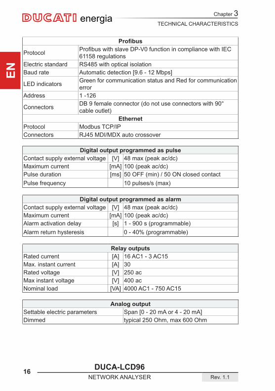
Profibus
Protocol ProfibuswithslaveDP-V0functionincompliancewithIEC61158 regulations
Electric standard RS485 with optical isolationBaud rate Automatic detection [9.6 - 12 Mbps]
LED indicators Green for communication status and Red for communication error
Address 1 -126
Connectors DB 9 female connector (do not use connectors with 90° cable outlet)
EthernetProtocol Modbus TCP/IPConnectors RJ45 MDI/MDX auto crossover
Digital output programmed as pulseContact supply external voltage [V] 48 max (peak ac/dc)Maximum current [mA] 100 (peak ac/dc)Pulse duration [ms] 50 OFF (min) / 50 ON closed contactPulse frequency 10 pulses/s (max)
Digital output programmed as alarmContact supply external voltage [V] 48 max (peak ac/dc)Maximum current [mA] 100 (peak ac/dc)Alarm activation delay [s] 1 - 900 s (programmable)Alarm return hysteresis 0 - 40% (programmable)
Relay outputsRated current [A] 16 AC1 - 3 AC15Max. instant current [A] 30Rated voltage [V] 250 acMax instant voltage [V] 400 acNominal load [VA] 4000 AC1 - 750 AC15
Analog outputSettable electric parameters Span [0 - 20 mA or 4 - 20 mA]Dimmed typical 250 Ohm, max 600 Ohm
TECHNICAL CHARACTERISTICS
DUCA-LCD96 17Rev. 1.1 NETWORK ANALYSER
Chapter 3
EN
energia
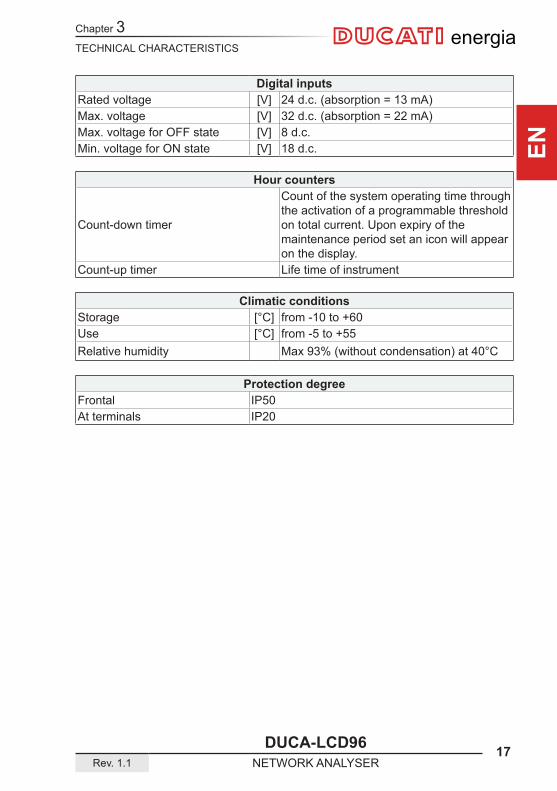
Digital inputsRated voltage [V] 24 d.c. (absorption = 13 mA)Max. voltage [V] 32 d.c. (absorption = 22 mA)Max. voltage for OFF state [V] 8 d.c.Min. voltage for ON state [V] 18 d.c.
Hour counters
Count-down timer
Count of the system operating time through the activation of a programmable threshold on total current. Upon expiry of the maintenance period set an icon will appear on the display.
Count-up timer Life time of instrument
Climatic conditionsStorage [°C] from -10 to +60Use [°C] from -5 to +55Relative humidity Max 93% (without condensation) at 40°C
Protection degreeFrontal IP50At terminals IP20

Chapter 4
18 DUCA-LCD96NETWORK ANALYSER Rev. 1.1
INSTALLATION
ENenergia
A x 4
1
2
IEC 61554
A
A
A A
A
4 INSTALLATION
4.1 Assembly
INSTALLATION
DUCA-LCD96 19Rev. 1.1 NETWORK ANALYSER
Chapter 4
EN
energia
A x 4
1
12
3
A
A A
A
A
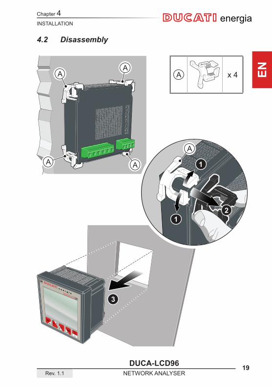
4.2 Disassembly
Chapter 4
20 DUCA-LCD96NETWORK ANALYSER Rev. 1.1
INSTALLATION
ENenergia
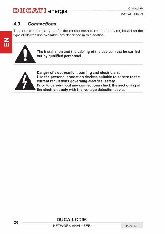
4.3 ConnectionsThe operations to carry out for the correct connection of the device, based on the type of electric line available, are described in this section.
The installation and the cabling of the device must be carried outbyqualifiedpersonnel.
Danger of electrocution, burning and electric arc.Use the personal protection devices suitable to adhere to the current regulations governing electrical safety.Prior to carrying out any connections check the sectioning of the electric supply with the voltage detection device.

INSTALLATION
DUCA-LCD96 21Rev. 1.1 NETWORK ANALYSER
Chapter 4
EN
energia
DU
CA
-LC
D96
/ D
UC
A-L
CD
96 B
ASE
24-240V|
AC-DC |L3 L2 L1 N| 1 2 | 1 2
OUT2 | OUT1
I1
I2
I3
S2
S1
S2
S1
S2
S1
Max 500 V DU
CA
-LC
D96
485
24-240V|
AC-DC |L3 L2 L1 N| 1 2 | 1 2
OUT2 | OUT1
I1
I2
I3
S2
S1
S2
S1
S2
S1
BSAT
Max 500 V
DU
CA
-LC
D96
-ETH
48-240V|
AC-DC |L3 L2 L1 N| 1 2 | 1 2
OUT2 | OUT1
I1
I2
I3
S2
S1
S2
S1
S2
S1
LAN
Max 500 V
DU
CA
-LC
D96
-PR
OFI
48-240V|
AC-DC |L3 L2 L1 N| 1 2 | 1 2
OUT2 | OUT1
I1
I2
I3
S2
S1
S2
S1
S2
S1
Profibus
Max 500 V
DU
CA
-LC
D96
485
-REL
E
24-240V|
AC-DC |L3 L2 L1 N| 1 2 | 1 2
OUT2 | OUT1
OUT4 OUT3
I1
I2
I3
S2
S1
S2
S1
S2
S1
BSAT
C NO NC | C NO NC
Max 500 V
DU
CA
-LC
D96
485
-IO
48-240V| Max 500 V
AC-DC |L3 L2 L1 N| 1 2 | 1 2
OUT2 | OUT1
I1
I2
I3
S2
S1
S2
S1
S2
S1
BSAT
+ COM + COM
AN-01 AN-02
+ - + - + -
IN1 | IN2 | SYNC
Chapter 4
22 DUCA-LCD96NETWORK ANALYSER Rev. 1.1
INSTALLATION
ENenergia
1A A
B
2A A
B
3
TV3 TV2 TV1
B
A
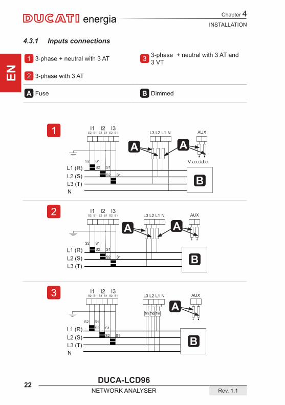
4.3.1 Inputs connections
1 3-phase + neutral with 3 AT 3 3-phase + neutral with 3 AT and 3 VT
2 3-phase with 3 AT
A Fuse B Dimmed
V a.c./d.c.

INSTALLATION
DUCA-LCD96 23Rev. 1.1 NETWORK ANALYSER
Chapter 4
EN
energia
4
TV3 TV1
B
A
5
A
B
A
6
A
B
A
4 AARON 3-phase with 2 AT and 3 VT 6 Balanced 3-phase with 1 AT
5 Monophase with 1 AT
A Fuse B Dimmed
Not suitable for the DUCA-LCD96 BASE model.

Chapter 4
24 DUCA-LCD96NETWORK ANALYSER Rev. 1.1
INSTALLATION
ENenergia
7
B
A8
C
A
9
ED
4.3.2 Optional outputs connections
7 Digital outlets as alarms with external relay for loads command 9 Electromechanical relay outputs
DUCA-LCD96 485-RELE
8 Digital outputs as pulses
A V aux 48 V a.c./d.c. 100 mA D Load 16A AC1 - 3A AC15
B External relay E V aux 250 V a.c. MAX
C Pulse acquisition
INSTALLATION
DUCA-LCD96 25Rev. 1.1 NETWORK ANALYSER
Chapter 4
EN
energia
10F
G
11 + +
H H
12B
A (+)GNDB (-)
120 Ohm
S A T
I
J
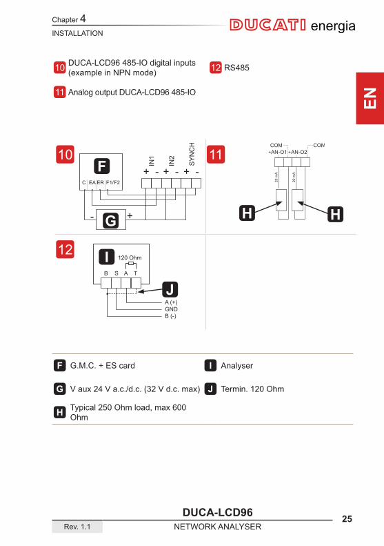
10 DUCA-LCD96 485-IO digital inputs(example in NPN mode) 12 RS485
11 Analog output DUCA-LCD96 485-IO
F G.M.C. + ES card I Analyser
G V aux 24 V a.c./d.c. (32 V d.c. max) J Termin. 120 Ohm
H Typical 250 Ohm load, max 600 Ohm
Chapter 4
26 DUCA-LCD96NETWORK ANALYSER Rev. 1.1
INSTALLATION
ENenergia
4.4 Configurations for first useAfter having cabled the instrument according to the pre-selected layout, the following operations must be carried out to start to use the analyser:
1) set the language (see paragraph “5.3.9 Language menu”)2) set the CT transformation ratio (see “5.3.4.2 Set CT ratio”)3) set the VT transformation ratio (see “5.3.4.3 Set VT ratio”)

OPERATING
DUCA-LCD96 27Rev. 1.1 NETWORK ANALYSER
Chapter 5
EN
energia
e n e r g i aDUCA-LCD96
VIP E L MIXMAX
MINAVG
OKSETUP
Alarm Setup
L31
L23
L12
51 2 3 4
6
13
14
18
17
19
8
7
9
15
16
10
11
12
5 OPERATING
5.1 Front panel

Chapter 5
28 DUCA-LCD96NETWORK ANALYSER Rev. 1.1
OPERATING
ENenergia
Description
1 Control key 1
2 Control key 2
3 Control key 3
4 Control key 4
5 Control key 5
6 Control keys unit
7 Device error or warning indicator
8 Data transmission to external devices indicator
9 Indicator for data acquisition on 4 quadrants-GENERATION
10 Alarm indicators
11 Hours counter indicator
12 SETUP mode indicator
13 Scrolling descriptive text
14 Descriptive or data display text
15 Size reading values
16 Measurement unit
17 Line indicator corresponding to value displayed
18 Indicator of capacitive load (PF and reactive power page)
19 Indicator of inductive load (PF and reactive power page)

OPERATING
DUCA-LCD96 29Rev. 1.1 NETWORK ANALYSER
Chapter 5
EN
energia
5.2 Use of deviceDuring normal operating or during the reading of the parameters, the device is set in DATA READING mode.Duringtheconfigurationphaseofoneormoreparametersthedevicewillpassonto the SETUP mode (signalled on display by the 12 icon).Based on the mode activate, the control keys 6 performaspecificfunction.
Passing from the DATA READING to SETUP mode and viceversa occurs by keeping the 5 key pressed down for over 2 seconds.
If the 7 icon is active when switching on, the device is signalling an installation or internal electronic anomaly.See paragraphs “5.3.10 Self-diagnosis menu” and “6.1 Problems, causes, solutions” to check the anomaly and solve the problem.
Chapter 5
30 DUCA-LCD96NETWORK ANALYSER Rev. 1.1
OPERATING
ENenergia
Setup
x1 x1 x1
>2s
XXXXXXXXXXXXXXXX XXXXXXXXXXXXXXXX
A
C D
B
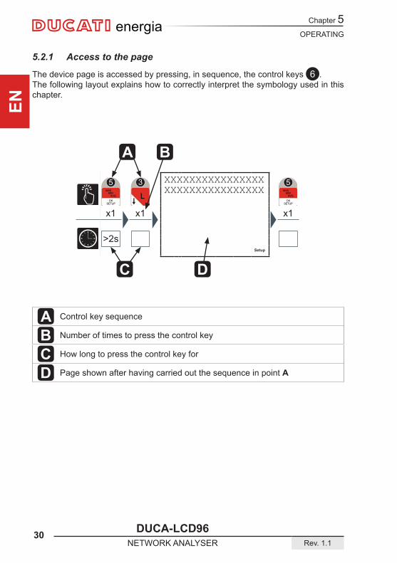
5.2.1 Access to the page
The device page is accessed by pressing, in sequence, the control keys 6 .The following layout explains how to correctly interpret the symbology used in this chapter.
A Control key sequence
B Number of times to press the control key
C How long to press the control key for
D Page shown after having carried out the sequence in point A
OPERATING
DUCA-LCD96 31Rev. 1.1 NETWORK ANALYSER
Chapter 5
EN
energia
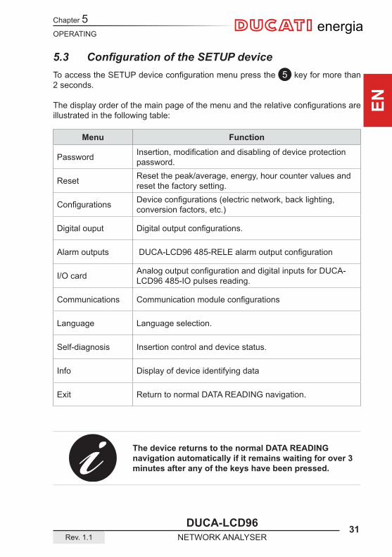
5.3 Configuration of the SETUP deviceToaccesstheSETUPdeviceconfigurationmenupressthe 5 key for more than 2 seconds.
Thedisplayorderofthemainpageofthemenuandtherelativeconfigurationsareillustrated in the following table:
Menu Function
Password Insertion,modificationanddisablingofdeviceprotectionpassword.
Reset Reset the peak/average, energy, hour counter values and reset the factory setting.
Configurations Deviceconfigurations(electricnetwork,backlighting,conversion factors, etc.)
Digital ouput Digitaloutputconfigurations.
Alarm outputs DUCA-LCD96485-RELEalarmoutputconfiguration
I/O card AnalogoutputconfigurationanddigitalinputsforDUCA-LCD96 485-IO pulses reading.
Communications Communicationmoduleconfigurations
Language Language selection.
Self-diagnosis Insertion control and device status.
Info Display of device identifying data
Exit Return to normal DATA READING navigation.
The device returns to the normal DATA READING navigation automatically if it remains waiting for over 3 minutes after any of the keys have been pressed.
Chapter 5
32 DUCA-LCD96NETWORK ANALYSER Rev. 1.1
OPERATING
ENenergia
Repeatedly press the 1 key to reach the Exit page, regardless of navigation point.Press the 5 keytoconfirm.
To quickly return to the normal DATA READING navigation, keep the 5 key pressed down for more than 2 seconds.
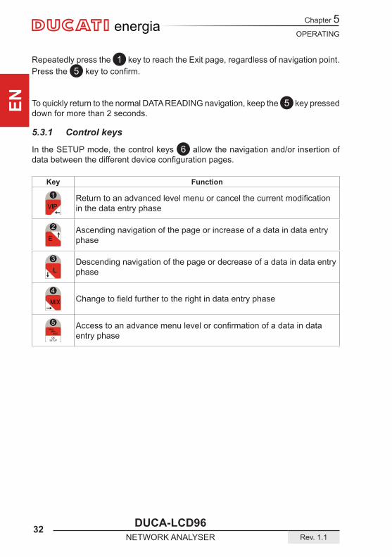
5.3.1 Control keys
In the SETUP mode, the control keys 6 allow the navigation and/or insertion of databetweenthedifferentdeviceconfigurationpages.
Key Function
Returntoanadvancedlevelmenuorcancelthecurrentmodificationin the data entry phase
Ascending navigation of the page or increase of a data in data entry phase
Descending navigation of the page or decrease of a data in data entry phase
Changetofieldfurthertotherightindataentryphase
Accesstoanadvancemenulevelorconfirmationofadataindataentry phase

OPERATING
DUCA-LCD96 33Rev. 1.1 NETWORK ANALYSER
Chapter 5
EN
energia
5.3.1.1 Data entry
Some of the pages require the entry of alphanumerical characters (A-Z, 0-9) in the SETUP mode.
In thesecasesthepagewillhaveaseriesoffieldswheretheactivefieldwillbeidentifiedbyaflashingcursor.
The data entry procedure (password, etc) is as follows:1) Use the 2 and 3 keys to scroll the alphanumerical characters available in either
ascending or descending order until the required character is obtained;2) Use the 4 key to move the cursor between the characters:3) Repeat the operations described in points 1 and 2 up to the completion of all the
fieldsonthepage:4) Press the 5 keytoconfirmorthe 1 keytocancelthemodification...
Chapter 5
34 DUCA-LCD96NETWORK ANALYSER Rev. 1.1
OPERATING
ENenergia
Setup
x1 x1 x1
>2s
Setup
x1 x1 x1 x1 x1
>2s
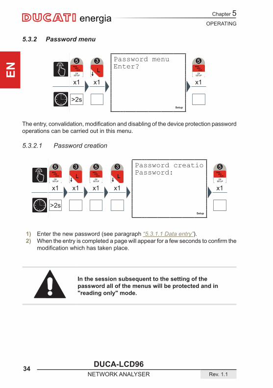
5.3.2 Password menu
Theentry,convalidation,modificationanddisablingofthedeviceprotectionpasswordoperations can be carried out in this menu.
5.3.2.1 Password creation
1) Enter the new password (see paragraph “5.3.1.1 Data entry”).2) Whentheentryiscompletedapagewillappearforafewsecondstoconfirmthe
modificationwhichhastakenplace.
In the session subsequent to the setting of the password all of the menus will be protected and in "reading only" mode.
Password menuEnter?
Password creatioPassword:
OPERATING
DUCA-LCD96 35Rev. 1.1 NETWORK ANALYSER
Chapter 5
EN
energia
Setup
x1 x1 x1 x1
>2s
Setup
x1 x1 x1 x1
>2s
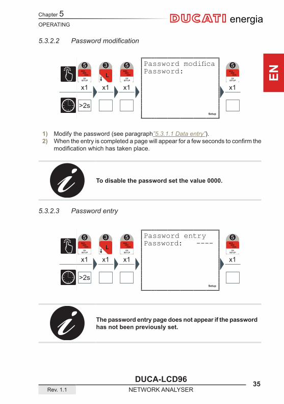
5.3.2.2 Passwordmodification
1) Modify the password (see paragraph”5.3.1.1 Data entry”).2) Whentheentryiscompletedapagewillappearforafewsecondstoconfirmthe
modificationwhichhastakenplace.
To disable the password set the value 0000.
5.3.2.3 Password entry
The password entry page does not appear if the password has not been previously set.
Password entryPassword: ----
Password modificaPassword:
Chapter 5
36 DUCA-LCD96NETWORK ANALYSER Rev. 1.1
OPERATING
ENenergia
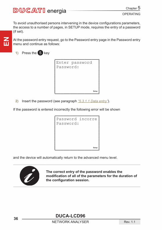
Toavoidunauthorisedpersonsinterveninginthedeviceconfigurationsparameters,the access to a number of pages, in SETUP mode, requires the entry of a password (if set).
At the password entry request, go to the Password entry page in the Password entry menu and continue as follows:
1) Press the 5 key
Enter password Password:
Setup
2) Insert the password (see paragraph “5.3.1.1 Data entry”).
If the password is entered incorrectly the following error will be shown
Password incorrePassword:
Setup
and the device will automatically return to the advanced menu level.
The correct entry of the password enables the modificationofalloftheparametersforthedurationoftheconfigurationsession.

OPERATING
DUCA-LCD96 37Rev. 1.1 NETWORK ANALYSER
Chapter 5
EN
energia
Setup
x1 x2 x1
>2s
The following operations can be carried out in this menu: • Peaks reset, the maximum, minimum and Maximum demand values are zeroed • Average values reset • Timer reset: T1 is zeroed, T2 starts from the value set • Balance reset partial of energy • Energy reset, all of the energy counts are zeroed, including the counts from
external impulses for DUCA-LCD96 485-IO • Total reset: resetting of the factory settings for all of the setup parameters
1) With the 2 or 3 keys select the page corresponding to the value you wish to reset.2) Press the 5 keytoconfirm.
Confirm reset<-esc OK-conf.
Setup
3) Press the 5 keytoconfirmtheselectionorthe 1 key to cancel and return to the advanced menu level.
5.3.3 Reset menu
Reset menu Enter?

Chapter 5
38 DUCA-LCD96NETWORK ANALYSER Rev. 1.1
OPERATING
ENenergia
Setup
x1 x3 x1 x1
>2s
Setup
x1 x3 x1
>2s
5.3.4 Configuration menu
In this menu the settings of the parameters relative to the entry of the electric network device, the T2 hour counter, the generation functions, the back lighting and the conversion factors used to calculate the values in euro and CO2 can be made.
5.3.4.1 Type of entry
1) Press the 2 or the 3 key to navigate between the following options: • GENERIC • MONOPHASE • BALANCED 3-PHASE • 3-PHASE (default)
2) Press the 5 keytoconfirm.
Configuration menEnter?
Type of entry GENERIC
OPERATING
DUCA-LCD96 39Rev. 1.1 NETWORK ANALYSER
Chapter 5
EN
energia
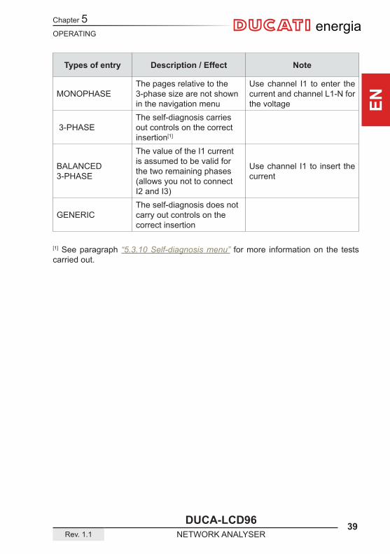
Types of entry Description / Effect Note
MONOPHASEThe pages relative to the 3-phase size are not shown in the navigation menu
Use channel I1 to enter the current and channel L1-N for the voltage
3-PHASEThe self-diagnosis carries out controls on the correct insertion[1]
BALANCED 3-PHASE
The value of the I1 current is assumed to be valid for the two remaining phases (allows you not to connect I2 and I3)
Use channel I1 to insert the current
GENERICThe self-diagnosis does not carry out controls on the correct insertion
[1] See paragraph “5.3.10 Self-diagnosis menu” for more information on the tests carried out.
Chapter 5
40 DUCA-LCD96NETWORK ANALYSER Rev. 1.1
OPERATING
ENenergia
Setup
x1 x3 x1 x1 x1
>2sA B
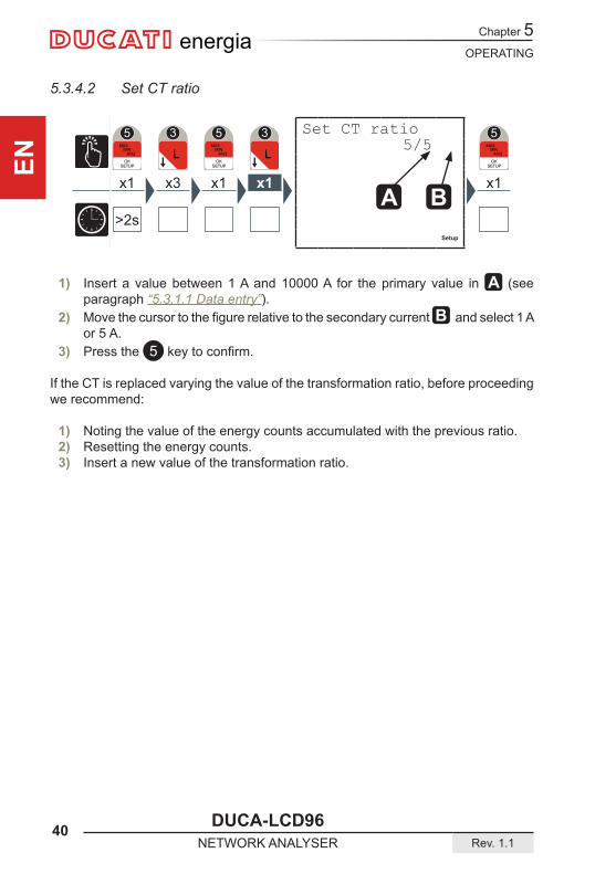
5.3.4.2 Set CT ratio
1) Insert a value between 1 A and 10000 A for the primary value in A (see paragraph “5.3.1.1 Data entry”).
2) MovethecursortothefigurerelativetothesecondarycurrentB and select 1 A or 5 A.
3) Press the 5 keytoconfirm.
If the CT is replaced varying the value of the transformation ratio, before proceeding we recommend:
1) Noting the value of the energy counts accumulated with the previous ratio.2) Resetting the energy counts.3) Insert a new value of the transformation ratio.
Set CT ratio 5/5
OPERATING
DUCA-LCD96 41Rev. 1.1 NETWORK ANALYSER
Chapter 5
EN
energia
Setup
x1 x3 x1 x2 x1
>2sA B
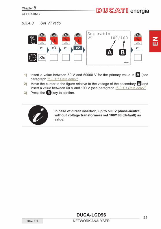
5.3.4.3 Set VT ratio
1) Insert a value between 60 V and 60000 V for the primary value in A (see paragraph “5.3.1.1 Data entry”).
2) Movethecursortothefigurerelativetothevoltageofthesecondary B and insert a value between 60 V and 190 V (see paragraph “5.3.1.1 Data entry”).
3) Press the 5 keytoconfirm.
In case of direct insertion, up to 500 V phase-neutral, without voltage transformers set 100/100 (default) as value.
Set ratioVT 100/100

Chapter 5
42 DUCA-LCD96NETWORK ANALYSER Rev. 1.1
OPERATING
ENenergia
Setup
x1 x3 x1 x3 x1
>2s
Setup
x1 x3 x1 x4 x1
>2s
5.3.4.4 Average time
In this page the time intervals used by the device to carry out the calculation of the average values is set.
1) Insert a value between 1 and 60 minutes (see paragraph “5.3.1.1 Data entry”).2) Press the 5 keytoconfirm.
5.3.4.5 Current threshold for T2 hour counter
The current threshold for the T2 hour counter represents the minimum current value at which the counter begins the countdown.
1) Insert a value of between 0 and the nominal value of the current transformer used, KA*5 (see paragraph “5.3.1.1 Data entry”).
2) Press the 5 keytoconfirm.
KA and KV respectively represent the ammetric and voltmetric transformation ratio.
Average time time(min) 15
Current thresholThrI(A) 0.00
OPERATING
DUCA-LCD96 43Rev. 1.1 NETWORK ANALYSER
Chapter 5
EN
energia
Setup
x1 x3 x1 x5 x1
>2s
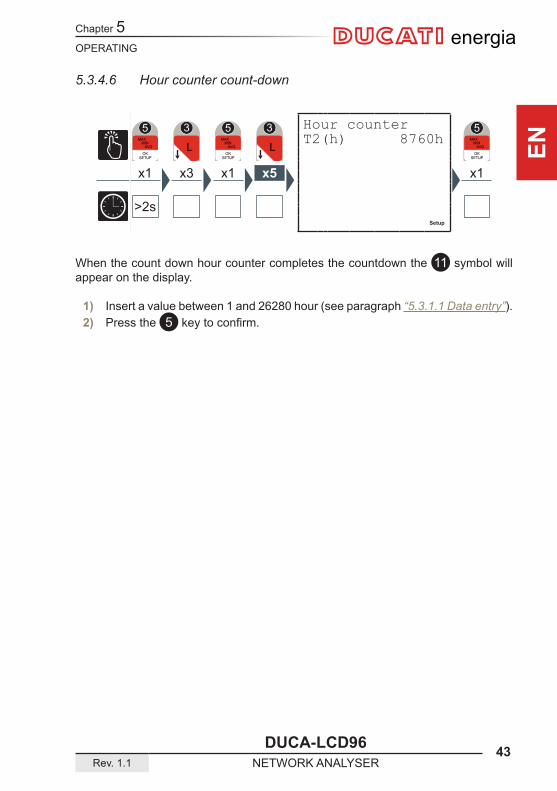
5.3.4.6 Hour counter count-down
When the count down hour counter completes the countdown the 11 symbol will appear on the display.
1) Insert a value between 1 and 26280 hour (see paragraph “5.3.1.1 Data entry”).2) Press the 5 keytoconfirm.
Hour counterT2(h) 8760h
Chapter 5
44 DUCA-LCD96NETWORK ANALYSER Rev. 1.1
OPERATING
ENenergia
Setup
x1 x3 x1 x6 x1
>2s
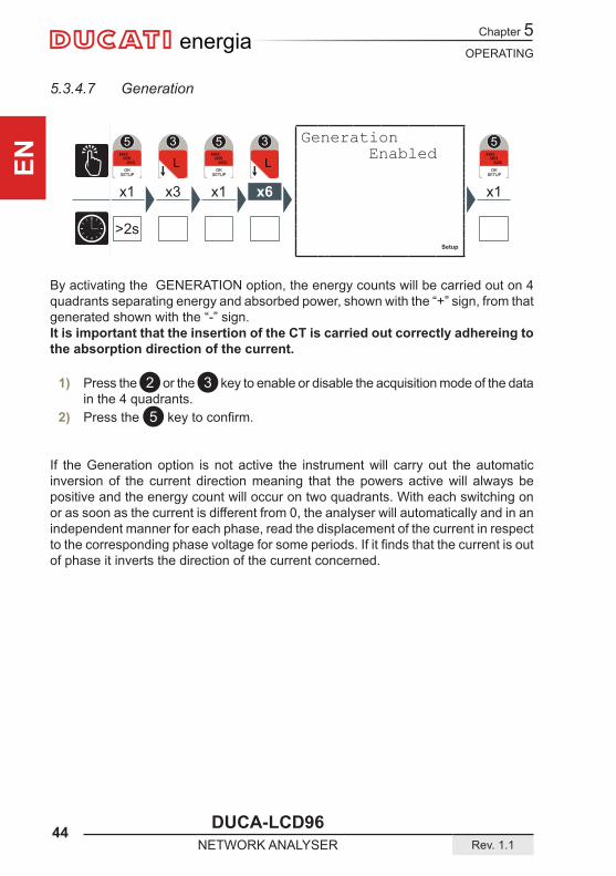
By activating the GENERATION option, the energy counts will be carried out on 4 quadrants separating energy and absorbed power, shown with the “+” sign, from that generated shown with the “-” sign.It is important that the insertion of the CT is carried out correctly adhereing to the absorption direction of the current.
1) Press the 2 or the 3 key to enable or disable the acquisition mode of the data in the 4 quadrants.
2) Press the 5 keytoconfirm.
If the Generation option is not active the instrument will carry out the automatic inversion of the current direction meaning that the powers active will always be positive and the energy count will occur on two quadrants. With each switching on or as soon as the current is different from 0, the analyser will automatically and in an independent manner for each phase, read the displacement of the current in respect tothecorrespondingphasevoltageforsomeperiods.Ifitfindsthatthecurrentisoutof phase it inverts the direction of the current concerned.
5.3.4.7 Generation
Generation Enabled

OPERATING
DUCA-LCD96 45Rev. 1.1 NETWORK ANALYSER
Chapter 5
EN
energia
c Setup
x1 x3 x1 x8 x1
>2s
c Setup
x1 x3 x1 x7 x1
>2s
conversion factor so that the equivalent can be displayed in Kg CO2.
1) Insert a value between 0.01 and 9.99 (see paragraph “5.3.1.1 Data entry”).2) Press the 5 keytoconfirm.
The active 3-phase energy, both absorbed and generated, is multiplied by the conversion factor so that the equivalent can be displayed in euro.
1) Insert a value between 0.01 and 9.99 (see paragraph “5.3.1.1 Data entry”).2) Press the 5 keytoconfirm.
5.3.4.9 CO2/energy factor
The active 3-phase energy, both absorbed and generated, is multiplied by the
5.3.4.8 Euro/energy factor
CO2/energy factoKg/KWh 0.05
Euro/energy fact€/KWh 0.18

Chapter 5
46 DUCA-LCD96NETWORK ANALYSER Rev. 1.1
OPERATING
ENenergia
Setup
x1 x3 x1 x9 x1
>2s
Setup
x1 x3 x1 x10 x1
>2s
5.3.4.10 Back lighting
The energy saving foresees the automatic switching off of the back lighting (if not set at “off”) if the control keys 6 remain inactive for approx. 3 minutes.The back lighting can be reactivated by pressing any of the 6 control keys.
1) Press the 2 key or the 3 key to enable or to disable the ‘Energy saving’ mode.2) Press the 5 keytoconfirm.
1) Press the 2 or the 3 key to navigate between the following options: • off • intermediate • maximum
2) Press the 5 keytoconfirm.
5.3.4.11 Energy saving
Back lighting interme
Energy saving Enabled
OPERATING
DUCA-LCD96 47Rev. 1.1 NETWORK ANALYSER
Chapter 5
EN
energia
Setup
x1 x4 x1 x1
>2s
c Setup
x1 x4 x1
>2s
5.3.5 Digital output menu
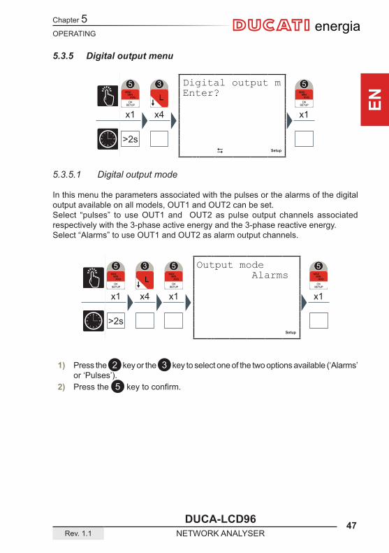
5.3.5.1 Digital output mode
In this menu the parameters associated with the pulses or the alarms of the digital output available on all models, OUT1 and OUT2 can be set.Select “pulses” to use OUT1 and OUT2 as pulse output channels associated respectively with the 3-phase active energy and the 3-phase reactive energy.Select “Alarms” to use OUT1 and OUT2 as alarm output channels.
1) Press the 2 key or the 3 key to select one of the two options available (‘Alarms’ or ‘Pulses’).
2) Press the 5 keytoconfirm.
Output mode Alarms
Digital output m Enter?
Chapter 5
48 DUCA-LCD96NETWORK ANALYSER Rev. 1.1
OPERATING
ENenergia
Setup
x1 x4 x1 x1 x1
>2s
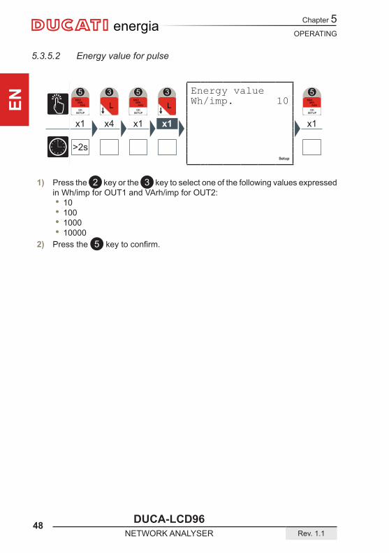
5.3.5.2 Energy value for pulse
1) Press the 2 key or the 3 key to select one of the following values expressed in Wh/imp for OUT1 and VArh/imp for OUT2:
• 10 • 100 • 1000 • 10000
2) Press the 5 keytoconfirm.
Energy valueWh/imp. 10

OPERATING
DUCA-LCD96 49Rev. 1.1 NETWORK ANALYSER
Chapter 5
EN
energia
Setup
x1 x4 x1 x2 x1x3(*)
>2s
5.3.5.3 Alarm1 or alarm2(*) parameter
1) Press the 2 key or the 3 key to navigate between the parameters given in paragraph “5.3.7.6 Output associated parameter table”.
2) Press the 5 keytoconfirm.
Alarm parameter None
Chapter 5
50 DUCA-LCD96NETWORK ANALYSER Rev. 1.1
OPERATING
ENenergia
Setup
x1 x4 x1 x5 x1
>2s
Setup
x1 x4 x1 x4 x1
>2s
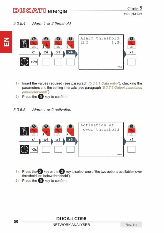
1) Press the 2 key or the 3 key to select one of the two options available (‘over threshold’ or ‘below threshold’).
2) Press the 5 keytoconfirm.
1) Insert the values required (see paragraph “5.3.1.1 Data entry”), checking the parameters and the setting intervals (see paragraph “5.3.7.6 Output associated parameter table”).
2) Press the 5 keytoconfirm.
5.3.5.5 Alarm 1 or 2 activation
5.3.5.4 Alarm 1 or 2 threshold
Activation at over threshold
Alarm threshold th2 1.00
OPERATING
DUCA-LCD96 51Rev. 1.1 NETWORK ANALYSER
Chapter 5
EN
energia
Setup
x1 x4 x1 x6 x1
>2s
Setup
x1 x4 x1 x7 x1
>2s
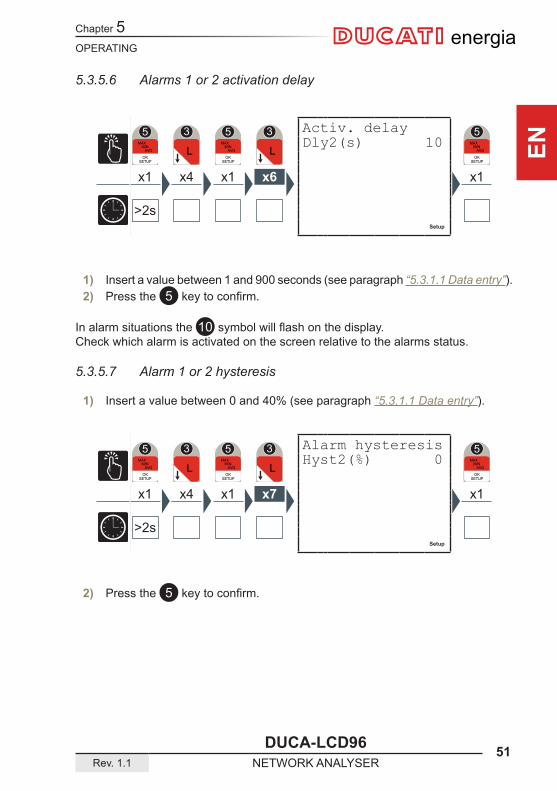
1) Insert a value between 1 and 900 seconds (see paragraph “5.3.1.1 Data entry”).2) Press the 5 keytoconfirm.
In alarm situations the 10 symbolwillflashonthedisplay.Check which alarm is activated on the screen relative to the alarms status.
5.3.5.7 Alarm 1 or 2 hysteresis
1) Insert a value between 0 and 40% (see paragraph “5.3.1.1 Data entry”).
5.3.5.6 Alarms 1 or 2 activation delay
2) Press the 5 keytoconfirm.
Activ. delayDly2(s) 10
Alarm hysteresisHyst2(%) 0

Chapter 5
52 DUCA-LCD96NETWORK ANALYSER Rev. 1.1
OPERATING
ENenergia
Setup
x1x1 x5 x2(*) x1
>2s
c Setup
x1 x5 x1
>2s
5.3.6 Alarm output menu
5.3.6.1 Alarm 3 or 4 parameter (*)
1) Press the 2 key or the 3 key to navigate between the parameters given in paragraph “5.3.7.6 Output associated parameter table”.
2) Press the 5 keytoconfirm.
Alarm output menEnter?
Alarm parameter None
OPERATING
DUCA-LCD96 53Rev. 1.1 NETWORK ANALYSER
Chapter 5
EN
energia
Setup
x1 x5 x1 x1 x1
>2s
Setup
x1 x5 x1 x2 x1
>2s
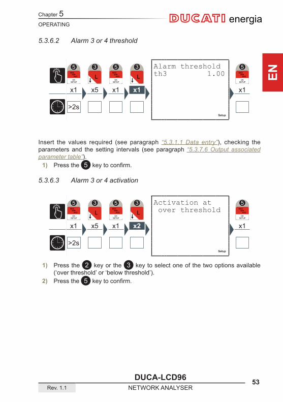
5.3.6.2 Alarm 3 or 4 threshold
Insert the values required (see paragraph “5.3.1.1 Data entry”), checking the parameters and the setting intervals (see paragraph “5.3.7.6 Output associated parameter table”).
1) Press the 5 keytoconfirm.
5.3.6.3 Alarm 3 or 4 activation
1) Press the 2 key or the 3 key to select one of the two options available (‘over threshold’ or ‘below threshold’).
2) Press the 5 keytoconfirm.
Alarm threshold th3 1.00
Activation at over threshold
Chapter 5
54 DUCA-LCD96NETWORK ANALYSER Rev. 1.1
OPERATING
ENenergia
Setup
x1 x5 x1 x3 x1
>2s
Setup
x1 x4 x1 x4 x1
>2s
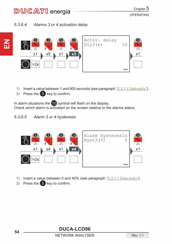
5.3.6.4 Alarms 3 or 4 activation delay
1) Insert a value between 1 and 900 seconds (see paragraph “5.3.1.1 Data entry”).2) Press the 5 keytoconfirm.
In alarm situations the 10 symbolwillflashonthedisplay.Check which alarm is activated on the screen relative to the alarms status.
5.3.6.5 Alarm 3 or 4 hysteresis
1) Insert a value between 0 and 40% (see paragraph “5.3.1.1 Data entry”).2) Press the 5 keytoconfirm.
Activ. delayDly3(s) 10
Alarm hysteresisHyst3(%) 0
OPERATING
DUCA-LCD96 55Rev. 1.1 NETWORK ANALYSER
Chapter 5
EN
energia
c Setup
x1 x5 x1
>2s
Setup
x1 x5 x1 x1
>2s
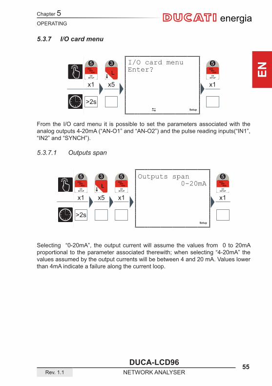
5.3.7 I/O card menu
From the I/O card menu it is possible to set the parameters associated with the analog outputs 4-20mA (“AN-O1” and “AN-O2”) and the pulse reading inputs(“IN1”, “IN2” and “SYNCH”).
5.3.7.1 Outputs span
Selecting “0-20mA”, the output current will assume the values from 0 to 20mA proportional to the parameter associated therewith; when selecting “4-20mA” the values assumed by the output currents will be between 4 and 20 mA. Values lower than 4mA indicate a failure along the current loop.
I/O card menu Enter?
Outputs span 0-20mA
Chapter 5
56 DUCA-LCD96NETWORK ANALYSER Rev. 1.1
OPERATING
ENenergia
Setup
x1 x5 x1 x1 x1
>2s
Setup
x1 x5 x1 x2 x1
>2s
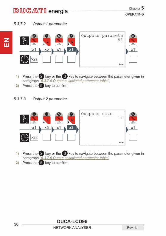
5.3.7.2 Output 1 parameter
1) Press the 2 key or the 3 key to navigate between the parameter given in paragraph “5.3.7.6 Output associated parameter table”.
2) Press the 5 keytoconfirm.
5.3.7.3 Output 2 parameter
1) Press the 2 key or the 3 key to navigate between the parameter given in paragraph “5.3.7.6 Output associated parameter table”.
2) Press the 5 keytoconfirm.
Outputs paramete V1
Outputs size l1
OPERATING
DUCA-LCD96 57Rev. 1.1 NETWORK ANALYSER
Chapter 5
EN
energia
Setup
x1 x4 x1 x3 x1
>2s
Setup
x1 x4 x1 x4 x1
>2s
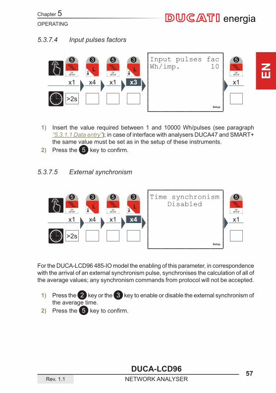
5.3.7.4 Input pulses factors
1) Insert the value required between 1 and 10000 Wh/pulses (see paragraph “5.3.1.1 Data entry”); in case of interface with analysers DUCA47 and SMART+ the same value must be set as in the setup of these instruments.
2) Press the 5 keytoconfirm.
5.3.7.5 External synchronism
For the DUCA-LCD96 485-IO model the enabling of this parameter, in correspondence with the arrival of an external synchronism pulse, synchronises the calculation of all of the average values; any synchronism commands from protocol will not be accepted.
1) Press the 2 key or the 3 key to enable or disable the external synchronism of the average time.
2) Press the 5 keytoconfirm.
Input pulses facWh/imp. 10
Time synchronism Disabled

Chapter 5
58 DUCA-LCD96NETWORK ANALYSER Rev. 1.1
OPERATING
ENenergia
5.3.7.6 Output associated parameter table
The following table shows the parameters associated to alarm ouput and/or analog output in current.
Parameter Measurement unit Max. limitFrequency Hz 500V12 concatenated voltage V KV * 866V23 concatenated voltage V KV * 866V31 concatenated voltage V KV * 866L1 voltage V KV * 500L2 voltage V KV * 500L3 voltage V KV * 500Equivalent 3-phase voltage V KV * 866L1 current A KA * 5L2 current A KA * 5L3 current A KA * 53-phase current A KA * 5L1 active power W KA * KV * 2500L2 active power W KA * KV * 2500L3 active power W KA * KV * 25003-phase active power W KA * KV * 7500L1 reactive power VAr KA * KV * 2500L2 reactive power VAr KA * KV * 2500L3 reactive power VAr KA * KV * 25003-phase reactive power VAr KA * KV * 7500L1 apparent power VA KA * KV * 2500L2 apparent power VA KA * KV * 2500L3 apparent power VA KA * KV * 25003-phase apparent power VA KA * KV * 7500PF1 1.00PF2 1.00PF3 1.003-phase PF 1.00T2(1) h Activated when 0 is reached(1) Parameter not associated to analog output in current.
KA and KV respectively represent the ammetric and voltmetric transformation ratio.

OPERATING
DUCA-LCD96 59Rev. 1.1 NETWORK ANALYSER
Chapter 5
EN
energia
Setup
x1 x4 x1 x1
>2s
Setup
x1 x4 x1
>2s
5.3.8 Communication menu
When the communication is active or the instrument is interrogated by a monitoring system and responds, the flashingcommunicationactive 8 symbol appears.
5.3.8.1 PROFIBUS address (only DUCA-LCD96-PROFI)
1) Enter the PROFIBUS node between 1 and 126 (see paragraph “5.3.1.1 Data entry”) to be associated with the instrument.
2) Press the 5 keytoconfirm.
This is the only page available in this menu for the DUCA-LCD96-PROFI model.
Nod address Addr 126
Communication meEnter?

Chapter 5
60 DUCA-LCD96NETWORK ANALYSER Rev. 1.1
OPERATING
ENenergia
Setup
x1 x4 x1 x1
>2s
Setup
x1 x4 x1 x1 x1
>2s
5.3.8.2 Serial protocol
1) Press the 2 key or the 3 key to select one of the two options available (‘MODBUS’ or ‘ASCII’).
2) Press the 5 keytoconfirm.
5.3.8.3 Address
1) Insert a value between 1 and 247(for Modbus protocol) or between 1 and 98 (for ASCII protocol) (see paragraph “5.3.1.1 Data entry”).
2) Press the 5 keytoconfirm.
Serial protocol Prot MODBUS
AddressAddr 31
OPERATING
DUCA-LCD96 61Rev. 1.1 NETWORK ANALYSER
Chapter 5
EN
energia
Setup
x1 x4 x1 x3 x1
>2s
Setup
x1 x4 x1 x2 x1
>2s
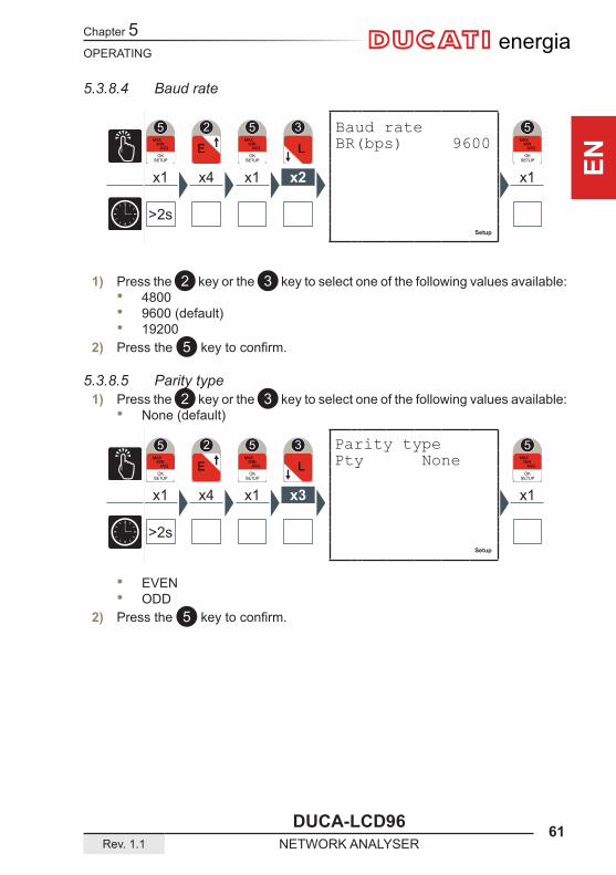
1) Press the 2 key or the 3 key to select one of the following values available: • 4800 • 9600 (default) • 19200
2) Press the 5 keytoconfirm.
5.3.8.5 Parity type1) Press the 2 key or the 3 key to select one of the following values available:
• None (default)
• EVEN • ODD
2) Press the 5 keytoconfirm.
5.3.8.4 Baud rate
Parity typePty None
Baud rateBR(bps) 9600
Chapter 5
62 DUCA-LCD96NETWORK ANALYSER Rev. 1.1
OPERATING
ENenergia
Setup
x1 x4 x1 x4 x1
>2s
Setup
x1 x4 x1 x1
>2s
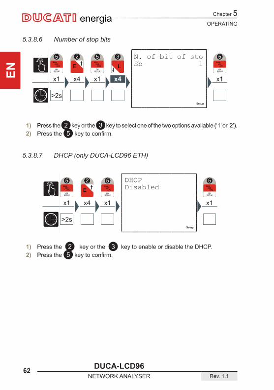
1) Press the 2 key or the 3 key to select one of the two options available (‘1’ or ‘2’).2) Press the 5 keytoconfirm.
5.3.8.7 DHCP (only DUCA-LCD96 ETH)
5.3.8.6 Number of stop bits
N. of bit of sto Sb 1
DHCPDisabled
1) Press the 2 key or the 3 key to enable or disable the DHCP.2) Press the 5 keytoconfirm.
OPERATING
DUCA-LCD96 63Rev. 1.1 NETWORK ANALYSER
Chapter 5
EN
energia
Setup
x1 x4 x1 x1 x1
>2s
Setup
x1 x4 x1 x2 x1
>2s
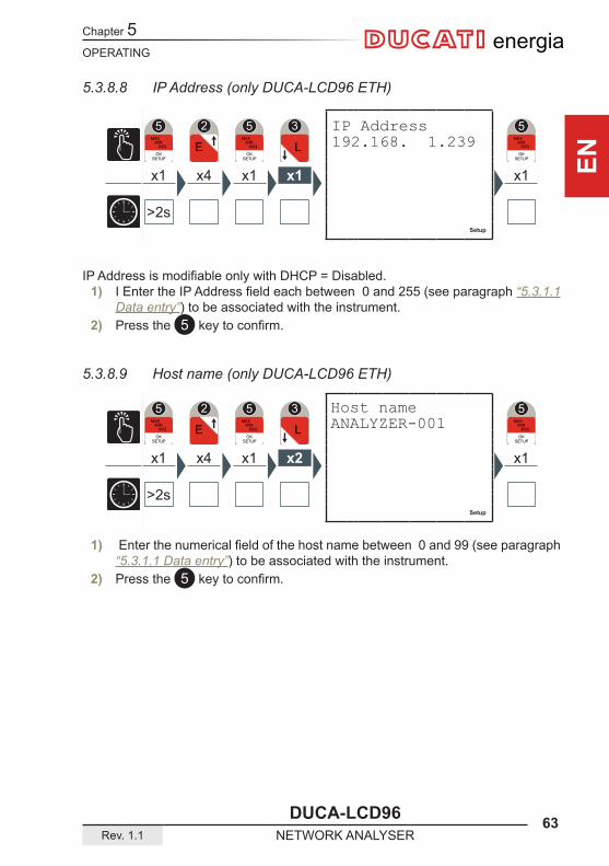
IP Address 192.168. 1.239
IPAddressismodifiableonlywithDHCP=Disabled.1) IEntertheIPAddressfieldeachbetween0and255(seeparagraph“5.3.1.1
Data entry”) to be associated with the instrument.2) Press the 5 keytoconfirm.
5.3.8.9 Host name (only DUCA-LCD96 ETH)
Host nameANALYZER-001
1) Enterthenumericalfieldofthehostnamebetween0and99(seeparagraph“5.3.1.1 Data entry”) to be associated with the instrument.
2) Press the 5 keytoconfirm.
5.3.8.8 IP Address (only DUCA-LCD96 ETH)
Chapter 5
64 DUCA-LCD96NETWORK ANALYSER Rev. 1.1
OPERATING
ENenergia
Setup
x1 x3 x1
>2s
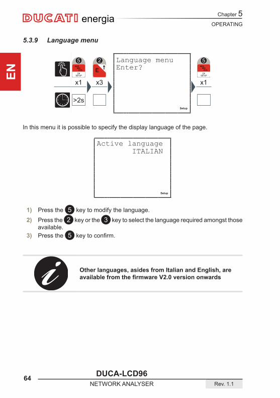
5.3.9 Language menu
In this menu it is possible to specify the display language of the page.
Active language ITALIAN
Setup
1) Press the 5 key to modify the language.
2) Press the 2 key or the 3 key to select the language required amongst those available.
3) Press the 5 keytoconfirm.
Other languages, asides from Italian and English, are availablefromthefirmwareV2.0versiononwards
Language menu Enter?
OPERATING
DUCA-LCD96 65Rev. 1.1 NETWORK ANALYSER
Chapter 5
EN
energia
Setup
x1 x2 x1
>2s
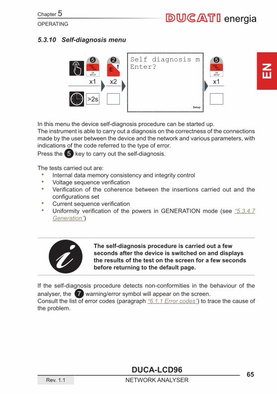
5.3.10 Self-diagnosis menu
In this menu the device self-diagnosis procedure can be started up.The instrument is able to carry out a diagnosis on the correctness of the connections made by the user between the device and the network and various parameters, with indications of the code referred to the type of error.Press the 5 key to carry out the self-diagnosis.
The tests carried out are: • Internal data memory consistency and integrity control • Voltagesequenceverification • Verification of the coherence between the insertions carried out and the
configurationsset • Currentsequenceverification • Uniformity verification of the powers inGENERATIONmode (see “5.3.4.7
Generation”)
The self-diagnosis procedure is carried out a few seconds after the device is switched on and displays the results of the test on the screen for a few seconds before returning to the default page.
If the self-diagnosis procedure detects non-conformities in the behaviour of the analyser, the 7 warning/error symbol will appear on the screen.Consult the list of error codes (paragraph “6.1.1 Error codes”) to trace the cause of the problem.
Self diagnosis mEnter?

Chapter 5
66 DUCA-LCD96NETWORK ANALYSER Rev. 1.1
OPERATING
ENenergia
Setup
x1 x1 x1
>2s
In this menu the identifying data of the device can be displayed, such as: • Typeofconfiguration • Series number • Firmware version
Press the 2 key or the 3 key to navigate between the pages and display the information required.
5.3.12 SETUP mode exit
To quickly exit from the SETUP mode keep the 5 key pressed for more than seconds.
5.3.11 Info menu
Info menu Enter?
OPERATING
DUCA-LCD96 67Rev. 1.1 NETWORK ANALYSER
Chapter 5
EN
energia
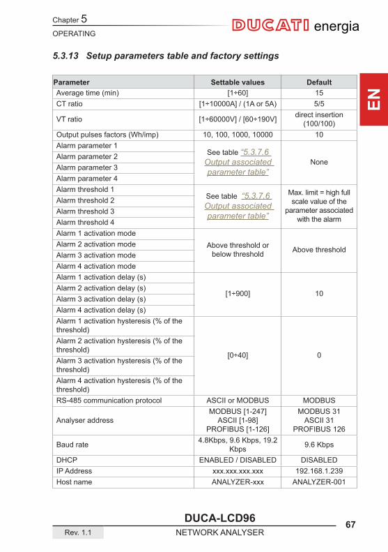
5.3.13 Setup parameters table and factory settings
Parameter Settable values DefaultAverage time (min) [1÷60] 15CT ratio [1÷10000A] / (1A or 5A) 5/5
VT ratio [1÷60000V] / [60÷190V] direct insertion (100/100)
Output pulses factors (Wh/imp) 10, 100, 1000, 10000 10Alarm parameter 1
See table “5.3.7.6 Output associated parameter table”
NoneAlarm parameter 2Alarm parameter 3Alarm parameter 4Alarm threshold 1
See table “5.3.7.6 Output associated parameter table”
Max. limit = high full scale value of the
parameter associated with the alarm
Alarm threshold 2Alarm threshold 3Alarm threshold 4Alarm 1 activation mode
Above threshold or below threshold Above threshold
Alarm 2 activation modeAlarm 3 activation modeAlarm 4 activation modeAlarm 1 activation delay (s)
[1÷900] 10Alarm 2 activation delay (s)Alarm 3 activation delay (s)Alarm 4 activation delay (s)Alarm 1 activation hysteresis (% of the threshold)
[0÷40] 0
Alarm 2 activation hysteresis (% of the threshold)Alarm 3 activation hysteresis (% of the threshold)Alarm 4 activation hysteresis (% of the threshold)RS-485 communication protocol ASCII or MODBUS MODBUS
Analyser addressMODBUS [1-247]
ASCII [1-98]PROFIBUS [1-126]
MODBUS 31ASCII 31
PROFIBUS 126
Baud rate 4.8Kbps, 9.6 Kbps, 19.2 Kbps 9.6 Kbps
DHCP ENABLED / DISABLED DISABLEDIP Address xxx.xxx.xxx.xxx 192.168.1.239Host name ANALYZER-xxx ANALYZER-001
Chapter 5
68 DUCA-LCD96NETWORK ANALYSER Rev. 1.1
OPERATING
ENenergia
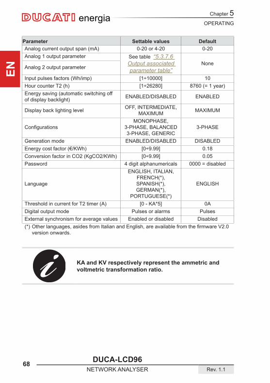
Parameter Settable values DefaultAnalog current output span (mA) 0-20 or 4-20 0-20Analog 1 output parameter See table “5.3.7.6
Output associated parameter table”
NoneAnalog 2 output parameter
Input pulses factors (Wh/imp) [1÷10000] 10Hour counter T2 (h) [1÷26280] 8760 (= 1 year)Energy saving (automatic switching off of display backlight) ENABLED/DISABLED ENABLED
Display back lighting level OFF, INTERMEDIATE, MAXIMUM MAXIMUM
ConfigurationsMONOPHASE,
3-PHASE, BALANCED 3-PHASE, GENERIC
3-PHASE
Generation mode ENABLED/DISABLED DISABLEDEnergy cost factor (€/KWh) [0÷9.99] 0.18Conversion factor in CO2 (KgCO2/KWh) [0÷9.99] 0.05Password 4 digit alphanumericals 0000 = disabled
Language
ENGLISH, ITALIAN, FRENCH(*), SPANISH(*), GERMAN(*),
PORTUGUESE(*)
ENGLISH
Threshold in current for T2 timer (A) [0 - KA*5] 0ADigital output mode Pulses or alarms PulsesExternal synchronism for average values Enabled or disabled Disabled(*) Otherlanguages,asidesfromItalianandEnglish,areavailablefromthefirmwareV2.0
version onwards.
KA and KV respectively represent the ammetric and voltmetric transformation ratio.

OPERATING
DUCA-LCD96 69Rev. 1.1 NETWORK ANALYSER
Chapter 5
EN
energia
5.4 Data readingIn DATA READING mode, the control keys 6 allow the navigation between the various reading pages of the parameter measured by the device.Each key has a series of pages grouped according to the logic reported in the following table:
Key Type of reading
Voltage, Currents and 3-phase powers, instant values, peak and average
Energies
Voltage, Currents and single phase powers
THD, alarms, hour counters and and external pulse counters
Access to peak, average and maximum demand values menus
Press the key corresponding to the data reading which you wish to carry out to display the start page.Each subsequent pressing of the same key cause the scrolling (cyclic) of the pages available up to the return to the start page.
Whenyoumovefromonekeytoanotherthefirstpagetobedisplayed is always the start page.
The display duration of a page is a maximum of 3 minutes after which the device will return to the default page.
5.4.1 Default page settingTo reset the default page:
1) Display the page you wish to set as the default page;2) Keep the 4 and 5 keys pressed down contemporaneously for more than 3
seconds.

Chapter 5
70 DUCA-LCD96NETWORK ANALYSER Rev. 1.1
OPERATING
ENenergia
x1
,3,9,8 V ,2.9,3 A ,1.9,9KW x2
L1 ,2,3,0 V L2 ,2,3,1 V L3 ,2,2,8 V
x3
L12 ,3,9,9 VL23 ,3,9,8 VL31 ,3,9,7 V x4
L1 ,3.4,0 AL2 ,1.3,0 AL3 ,4.1,0 A
x5
L1 ,7,7,4 WL2 ,3,0,0 WL3 ,9,2,5 W x6
L1 ,1,0,9 VArL2 , , ,0 VArL3 ,1,3,1 VAr
x7
L1 ,7,8,2 VAL2 ,3,0,0 VAL3 ,9,3,5 VA x8
L1 ,0.9,9L2 ,1.0,0L3 ,0.9,9
5.4.2 Voltages, Currents and 3-phase powers
Phase-neutral voltages
Reactive power
Currents
3-phase value
Apparent power Power factors
Active power
Concatenated voltages
3-phase valuePF 3F CAP0.99
Concatenated volFrq 50Hz
Active power3F 2.00KW
Apparent power3F 2.02KVA
Power factors3F CAP 0.99
Phase-neutral voFrq 50.0Hz
Currents3F 2.93A
Reactive power3F 240Var
OPERATING
DUCA-LCD96 71Rev. 1.1 NETWORK ANALYSER
Chapter 5
EN
energia
x1
L1 3,0,7.1KWhL2 2,7,2.0KWhL3 5,3,0.3KWh x2
L1 3,0.2,5KVArIL2 2,2.5,1KVArIL3 3,7.7,6KVArI
x3
L1 3,0,8.1KVAHL2 2,7,3.5KVAHL3 5,3,1.2KVAH x4
L1 8,0.2,1KWhL2 7,2.3,0KWhL3 7,3.8,8KWh
c
x5
L1 ,5,0,2 VArIL2 ,7,0,1 VArIL3 ,1,0,0 VArI
c
x6
L1 8,0.9,0KVAHL2 7,2.8,5KVAHL3 7,4.0,6KVAH
c
x7
, ,1,0KWh , , ,1KVArI , ,1,0KVAH
c
x8
8,8,3.0KWh8,9.2,2KVArI8,8,5.0KVAH
c
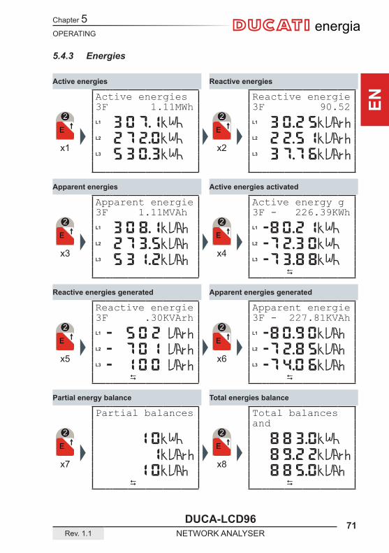
5.4.3 Energies
Reactive energies
Total energies balance
Apparent energies generated
Active energies activated
Active energies
Partial energy balance
Reactive energies generated
Apparent energies
Active energies3F 1.11MWh
Apparent energie3F 1.11MVAh
Reactive energie3F .30KVArh
Partial balances
Reactive energie3F 90.52
Active energy g3F - 226.39KWh
Apparent energie3F - 227.81KVAh
Total balances and
Chapter 5
72 DUCA-LCD96NETWORK ANALYSER Rev. 1.1
OPERATING
ENenergia
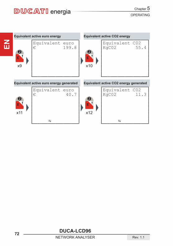
x9 x10
x11
c
x12
c
Equivalent active CO2 energy
Equivalent active CO2 energy generated
Equivalent active euro energy
Equivalent active euro energy generated
Equivalent euro€ 199.8
Equivalent euro€ 40.7
Equivalent C02KgC02 55.4
Equivalent C02KgC02 11.3
OPERATING
DUCA-LCD96 73Rev. 1.1 NETWORK ANALYSER
Chapter 5
EN
energia
x1
L1 ,2,3,0 V ,3.4,0 A
,7,7,4 W x2
L1 ,7,7,4 W ,1,0,9 VAr ,7,8,2 VA
x3
,2,3,1 VL2 ,1.3,0 A
,3,0,0 W x4
,3,0,0 WL2 , , ,0 VAr
,3,0,0 VA
x5
,2,2,8 V ,4.1,0 A
L3 ,9,2,5 W x6
,9,2,5 W ,1,3,1 VAr
L3 ,9,3,5 VA
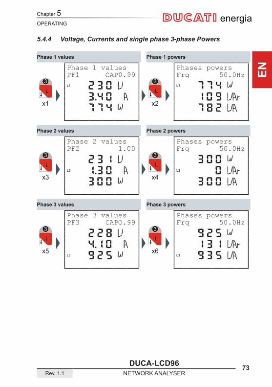
5.4.4 Voltage, Currents and single phase 3-phase Powers
Phase 1 powers
Phase 3 powers
Phase 2 powers
Phase 1 values
Phase 3 values
Phase 2 values
Phase 1 valuesPF1 CAP0.99
Phase 2 valuesPF2 1.00
Phase 3 valuesPF3 CAPO.99
Phases powersFrq 50.0Hz
Phases powersFrq 50.0Hz
Phases powersFrq 50.0Hz
Chapter 5
74 DUCA-LCD96NETWORK ANALYSER Rev. 1.1
OPERATING
ENenergia
x1
L1 , , ,1L2 , , ,0L3 , , ,1 x2
L1 ,1.0,1L2 ,1.0,0L3 ,1.0,1
x3
L1 , ,1,3L2 , , ,2L3 , , ,3 x4
L1 ,1.1,3L2 ,0.9,8L3 ,0.9,7
x5
3,on2,oFF1,oFF ,
Alarm
x6
x7 x8
,2.5,0KW
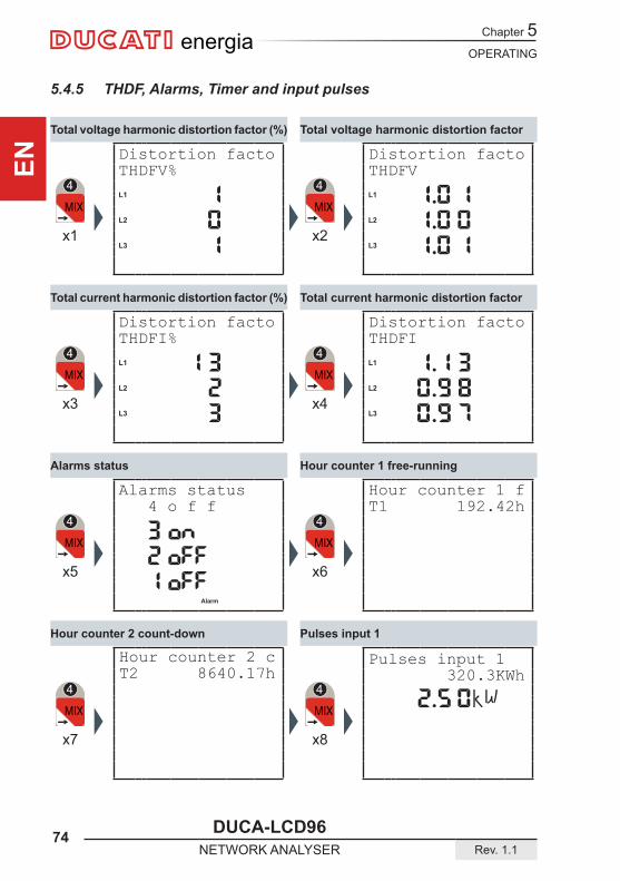
5.4.5 THDF, Alarms, Timer and input pulses
Total voltage harmonic distortion factor
Hour counter 1 free-running
Total current harmonic distortion factor
Total voltage harmonic distortion factor (%)
Hour counter 2 count-down Pulses input 1
Alarms status
Total current harmonic distortion factor (%)
Distortion factoTHDFV%
Distortion factoTHDFI%
Alarms status 4 o f f
Distortion factoTHDFV
Distortion factoTHDFI
Hour counter 1 fT1 192.42h
Hour counter 2 cT2 8640.17h
Pulses input 1 320.3KWh
OPERATING
DUCA-LCD96 75Rev. 1.1 NETWORK ANALYSER
Chapter 5
EN
energia
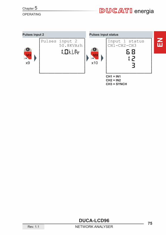
x9
, ,1.0KVAr
x10
, ,6,8 , ,1,2 , , ,3
Pulses input statusPulses input 2
Pulses input 2 50.8KVArh
Input 1 statusCH1-CH2-CH3
CH1 = IN1CH2 = IN2CH3 = SYNCH
Chapter 5
76 DUCA-LCD96NETWORK ANALYSER Rev. 1.1
OPERATING
ENenergia
x1
,4,0,0 V ,2.9,9 A ,2.1,0KW
L1 ,2,3,3 VL2 ,2,3,3 VL3 ,2,3,2 V
x1
x1
L12 ,4,0,3 VL23 ,4,0,2 VL31 ,4,0,2 V
L1 ,3.8,0 AL2 ,2.0,0 AL3 ,4.8,0 A
x1 x1
x2 x3
L1 ,8,8,0 WL2 ,4,6,0 WL3 ,1.1,0KW
L1 ,1,1,0 VArL2 , ,2,0 VArL3 ,1,4,0 VAr
x1 x1
x4 x5
L1 ,8,8,5 VAL2 ,4,6,5 VAL3 ,1.1,3KVA
x1
x6
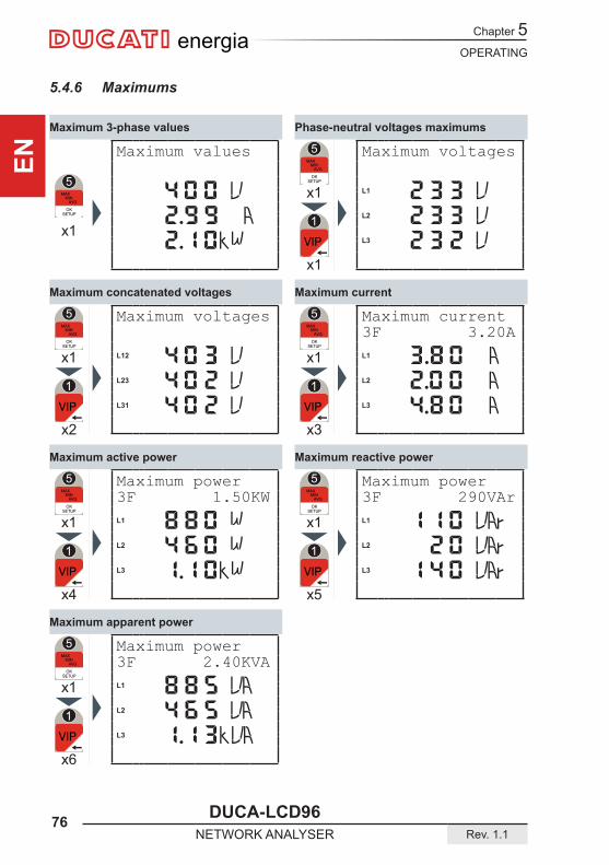
5.4.6 Maximums
Phase-neutral voltages maximums
Maximum reactive power
Maximum current
Maximum 3-phase values
Maximum apparent power
Maximum active power
Maximum concatenated voltages
Maximum values
Maximum voltages
Maximum power3F 1.50KW
Maximum power3F 2.40KVA
Maximum voltages
Maximum current3F 3.20A
Maximum power3F 290VAr

OPERATING
DUCA-LCD96 77Rev. 1.1 NETWORK ANALYSER
Chapter 5
EN
energia
x2
,3,9,8 V ,0.8,0 A ,2,0,0 W
L1 ,3,9,8 VL2 ,3,9,9 VL3 ,3,9,6 V
x2
x1
L1 , ,4,6 WL2 ,1,1,5 WL3 , ,2,3 W
L1 , , ,0 VArL2 , , ,0 VArL3 , , ,1 VAr
x2 x2
x4 x5
L12 ,3,9,9 VL23 ,3,9,8 VL31 ,3,9,7 V
L1 ,0.2,0 AL2 ,0.5,0 AL3 ,0.1,0 A
x2 x2
x2 x3
L1 , ,4,8 VAL2 ,1,1,9 VAL3 , ,2,5 VA
x1
x6
5.4.7 Minimums
Minimum phase-neutral voltages
Minimum reactive powers
Minimum currents
Minimum 3-phase values
Minimum apparent powers
Minimum active powers
Minimum concatenated voltages
Minimum values
Minimum voltages
Minimum powers3F 190W
Minimum powers3F 199VA
Minimum voltages
Minimum currents3F 0.80A
Minimum powers3F 4VAr
Chapter 5
78 DUCA-LCD96NETWORK ANALYSER Rev. 1.1
OPERATING
ENenergia
x4
L1 ,7,6,0 WL2 ,3,7,0 WL3 ,9,2,0 W
L1 ,8,1,0 VAL2 ,3,5,0 VAL3 ,1.0,1KVA
x4
x1
L1 ,7,8,0 VAL2 ,2,9,8 VAL3 ,9,3,7 VA
x3
x2
x3
L1 ,7,0,0 WL2 ,3,1,5 WL3 ,9,0,0 W
L1 ,1,0,0 VArL2 , , ,1 VArL3 ,1,3,0 VAr
x3
x1
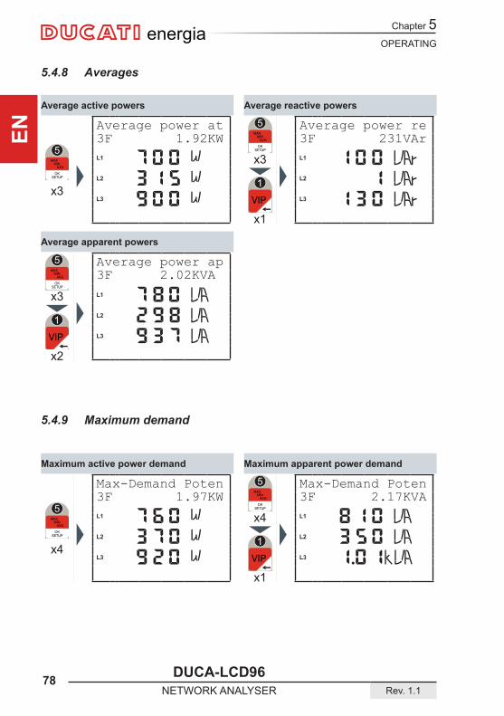
5.4.8 Averages
5.4.9 Maximum demand
Average reactive powersAverage active powers
Average apparent powers
Average power at 3F 1.92KW
Average power ap3F 2.02KVA
Average power re3F 231VAr
Maximum apparent power demandMaximum active power demand
Max-Demand Poten 3F 1.97KW
Max-Demand Poten 3F 2.17KVA
TROUBLESHOOTING
DUCA-LCD96 79Rev. 1.1 NETWORK ANALYSER
Chapter 6
EN
energia
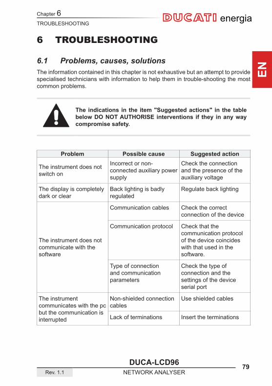
6 TROUBLESHOOTING
6.1 Problems, causes, solutionsThe information contained in this chapter is not exhaustive but an attempt to provide specialised technicians with information to help them in trouble-shooting the most common problems.
The indications in the item "Suggested actions" in the table below DO NOT AUTHORISE interventions if they in any way compromise safety.
Problem Possible cause Suggested action
The instrument does not switch on
Incorrect or non-connected auxiliary power supply
Check the connection and the presence of the auxiliary voltage
The display is completely dark or clear
Back lighting is badly regulated
Regulate back lighting
The instrument does not communicate with the software
Communication cables Check the correct connection of the device
Communication protocol Check that the communication protocol of the device coincides with that used in the software.
Type of connection and communication parameters
Check the type of connection and the settings of the device serial port
The instrument communicates with the pc but the communication is interrupted
Non-shielded connection cables
Use shielded cables
Lack of terminations Insert the terminations

Chapter 6
80 DUCA-LCD96NETWORK ANALYSER Rev. 1.1
TROUBLESHOOTING
ENenergia
6.1.1 Error codes
Code Type Description Suggested action
1 Internal memory error
Internal memory damaged
Contact the manufacturer
2 Voltage Errors V1 zero Check voltage presence
3Voltage Errors V2 and/or V3 zero with
config.=TRIPHASEorBALANCED 3-PHASE
Check voltage presence or set the correct configuration
4
Voltage Errors Voltage not at 120° amongst themselves withconfig.=3-PHASEor BALANCED 3-PHASE
Check voltage presence or set the correct configuration
5
Current Error I1 = 0 Check connection layoutscheck the TA connections and load presence
6 Current Error l2 and/or I3 zero with config.=3-PHASE
Setconfigurationcorrectly
7Warning V2 and/or V3 not
zerowithconfig.=SINGLEPHASE
Check the connection layouts or correctly set theconfiguration
8 Voltage sequence error
Possible inversions of 2 phases
Check connection layouts
9Warning l2 and/or I3 not zero with
config.=SINGLEPHASEor BALANCED 3-PHASE
Check the connection layouts or correctly set theconfiguration
10 Warning Possible current order inversion error
Check connection layouts
11 Warning Possible inversion of I1 and I2
Check connection layouts
12 Warning Possible inversion of I1 and I3
Check connection layouts
TROUBLESHOOTING
DUCA-LCD96 81Rev. 1.1 NETWORK ANALYSER
Chapter 6
EN
energia
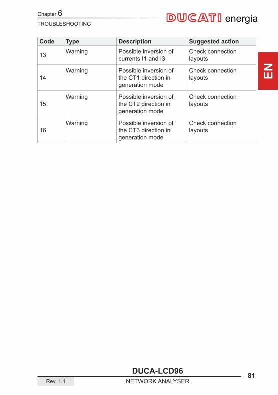
Code Type Description Suggested action
13 Warning Possible inversion of currents I1 and I3
Check connection layouts
14 Warning Possible inversion of
the CT1 direction in generation mode
Check connection layouts
15Warning Possible inversion of
the CT2 direction in generation mode
Check connection layouts
16Warning Possible inversion of
the CT3 direction in generation mode
Check connection layouts
Chapter 6
82 DUCA-LCD96NETWORK ANALYSER Rev. 1.1
TROUBLESHOOTING
ENenergia
If the operating problems have not been solved or the information is not contained in this manual, please contact the Technical Assistance Service.
Collect as much information as possible relative to the installation and, in particular, the following data:
1) Model and serial number of the instrument (data is indicated on the shield applied on the container at the rear).
2) Purchase date of the materials.3) Description of the problem.4) Systemconfiguration:typeofinsertion,CTandTVratio,connectionswithexternal
communication devices, etc.


energia
More info
Contact us
Via M. E. Lepido, 18240132 Bologna – ItalyPh.: +39 – 051 6411511Fax: +39 – 051 6411690
www.ducatienergia. com
E-mail (Sales): [email protected] (Technical): [email protected]
DUCATI Energia S.p.A cannot be held liable for any damage or personal injury arising from incorrect or improper use of its equipments.These documents are subject to changes without prior notice.Document code: Version 1.1 – July 2014