DUC UNDERCUT ANCHORS - mitek-us.com · accordance with ACI 355.2, meeting the requirements for...
18
USP Structural Connectors • 1-800-328-5934 • www.USPconnectors.com • 14305 Southcross Drive, Suite 200 • Burnsville, MN 55306 45 DUC UNDERCUT ANCHORS 4.0 DUC Undercut Anchors 4.1 Product Information 4.1.1 Description 4.1.2 Product Features 4.1.3 Code Reports/Listings/Test Standards 4.1.4 Suggested Specification 4.1.5 DUC Anchor Component Material Specifications 4.2 Performance Parameters 4.2.1 Behavior or Anchors in Concrete 4.2.2 Anchor Working Principals 4.2.3 DUC Undercut Anchor Testing and Performance Evaluation 4.3 Specification and Installation Details 4.3.1 DUC Anchor Dimensional Information 4.3.2 DUC Anchor Installation Details 4.3.3 DUC Anchor Installation Procedures 4.4 2003/06 IBC (ACI 318-02/05, Appendix D) Anchor Design 4.4.1 Introduction 4.4.2 Strength Design 4.4.3 Allowable Stress Design
Transcript of DUC UNDERCUT ANCHORS - mitek-us.com · accordance with ACI 355.2, meeting the requirements for...

USP Structural Connectors • 1-800-328-5934 • www.USPconnectors.com • 14305 Southcross Drive, Suite 200 • Burnsville, MN 55306
45
DUC UNDERCUT ANCHORS
4.0 DUC Undercut Anchors
4.1 Product Information
4.1.1 Description 4.1.2 Product Features 4.1.3 Code Reports/Listings/Test Standards 4.1.4 Suggested Specification 4.1.5 DUC Anchor Component Material Specifications
4.2 Performance Parameters
4.2.1 Behavior or Anchors in Concrete 4.2.2 Anchor Working Principals 4.2.3 DUC Undercut Anchor Testing and Performance Evaluation
4.3 Specification and Installation Details
4.3.1 DUC Anchor Dimensional Information 4.3.2 DUC Anchor Installation Details 4.3.3 DUC Anchor Installation Procedures
4.4 2003/06 IBC (ACI 318-02/05, Appendix D) Anchor Design
4.4.1 Introduction 4.4.2 Strength Design 4.4.3 Allowable Stress Design
46
USP Structural Connectors • 1-800-328-5934 • www.USPconnectors.com • 14305 Southcross Drive, Suite 200 • Burnsville, MN 55306
DUC UNDERCUT ANCHORS
4.1 Product Details - DUC Undercut Anchors
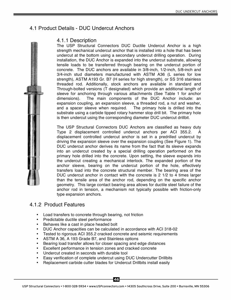
4.1.1 Description The USP Structural Connectors DUC Ductile Undercut Anchor is a high strength mechanical undercut anchor that is installed into a hole that has been undercut at the bottom using a secondary undercut drilling operation. During installation, the DUC Anchor is expanded into the undercut substrate, allowing tensile loads to be transferred through bearing on the undercut portion of concrete. The DUC anchors are available in 3/8-inch, 1/2-inch, 5/8-inch and 3/4-inch stud diameters manufactured with ASTM A36 (L series for low strength), ASTM A193 Gr. B7 (H series for high strength), or SS 316 stainless threaded rod. Additionally, stock anchors are available in standard and Through-bolted versions (T designated) which provide an additional length of sleeve for anchoring through various attachments (See Table 1 for anchor dimensions). The main components of the DUC Anchor include: an expansion coupling, an expansion sleeve, a threaded rod, a nut and washer, and a spacer sleeve when required. The primary hole is drilled into the substrate using a carbide tipped rotary hammer stop drill bit. The primary hole is then undercut using the corresponding diameter DUC undercut drillbit.
The USP Structural Connectors DUC Anchors are classified as heavy duty Type 2 displacement controlled undercut anchors per ACI 355.2. A displacement controlled undercut anchor is set in a predrilled undercut by driving the expansion sleeve over the expansion coupling (See Figure 1). The DUC undercut anchor derives its name from the fact that its sleeve expands into an undercut created by a special drilling operation performed on the primary hole drilled into the concrete. Upon setting, the sleeve expands into the undercut creating a mechanical interlock. The expanded portion of the anchor sleeve, bearing on the undercut portion of the hole, effectively transfers load into the concrete structural member. The bearing area of the DUC undercut anchor in contact with the concrete is 2 1/2 to 4 times larger than the tensile area of the anchor rod, depending on the specific anchor geometry. This large contact bearing area allows for ductile steel failure of the anchor rod in tension, a mechanism not typically possible with friction-only type expansion anchors.
4.1.2 Product Features
• Load transfers to concrete through bearing, not friction • Predictable ductile steel performance • Behaves like a cast in place headed bolt • DUC Anchor capacities can be calculated in accordance with ACI 318-02 • Tested to rigorous ACI 355.2 cracked concrete and seismic requirements • ASTM A 36, A 193 Grade B7, and Stainless options • Bearing load transfer allows for closer spacing and edge distances • Excellent performance in tension zones and cracked concrete • Undercut created in seconds with durable tool • Easy verification of complete undercut using DUC Undercutter Drillbits • Replacement carbide cutter blades for Undercut Drillbits install easily

47
USP Structural Connectors • 1-800-328-5934 • www.USPconnectors.com • 14305 Southcross Drive, Suite 200 • Burnsville, MN 55306
DUC UNDERCUT ANCHORS
4.1.3 Code Reports/ Listings/ Test Standards (See section 8.0 for further information)
ICC (ICBO) ES ESR 1970 – ICC Evaluation Service, Inc RR25753 – City of Los Angeles Research Report FL 4928 – Florida Statewide Building Code product Approval Meets ACI 318-02/05 Appendix D – Anchoring to Concrete Evaluated under ACI 355.2 - Performance of Post Installed Mechanical Anchors in Concrete Evaluated under ICC ES AC 193- Mechanical Anchors in Concrete Elements
4.1.4 Suggested Specification
Anchors installed into hardened concrete shall be DUC Ductile Undercut Anchors, manufactured by USP Structural Connectors, Burnsville, MN, per ICC ES ESR 1970. Anchors shall have been qualified for use in cracked concrete and for seismic applications in accordance with ACI 355.2, meeting the requirements for Category 1 classification. See structural details for diameter, embedment, spacing and edge distance or follow manufacturers’ recommendations if not shown in details. Follow all manufacturers’ installation instructions.
4.1.5 DUC Anchor component material specifications
Component Material Spec. fy (psi) fu (psi)L Series Threaded Rod ASTM A 36 36000 58000H Series Threaded Rod ASTM A 193 Gr. B7 105000 125000Expansion Coupling ASTM A 108 12L14 70000 78000Expansion Sleeve ASTM A 513 Type 5 70000 80000Spacer Sleeve ASTM A 513 Type 5 70000 80000Hex Nut ASTM A 563, Gr. C -- --Washer ASTM F 844 -- --
4.2 Performance Parameters
4.2.1 Behavior of Anchors in Concrete
The strength and serviceability of anchors in concrete are affected by many factors. Some of these factors are under the control of the anchor manufacturer such as the mechanical strength and corrosion resistance properties of a specifically selected anchor material, or the design of the geometry of the anchors’ load transfer mechanism to the concrete. Other factors are not under the control of the manufacturer, including installation in corrosive environments, subjection to seismic, long term, or shock loading conditions, installation with drill bits that are out of the specified diameter range, installation into tension zones in concrete subject to cracking, close spacing and edge conditions, etc. Although the manufacturer cannot control where and how an anchor is installed and loaded when in service, the manufacturer can design and test the anchor for proper performance in most of these conditions.
One anchor installation condition that has been shown to have a marked effect on the tensile strength and serviceability of anchors is installation in areas where there is a likelihood of the concrete cracking. Reinforced concrete design is largely based upon the principle that
48
USP Structural Connectors • 1-800-328-5934 • www.USPconnectors.com • 14305 Southcross Drive, Suite 200 • Burnsville, MN 55306
DUC UNDERCUT ANCHORS
concrete has low strength in tension, and steel reinforcement is provided to carry the tensile loads in concrete members, even at the service load level in many cases. In order for the structural element to properly transfer the tensile loads into the steel reinforcement, the concrete must crack. These cracks are a result of flexure in beams and slabs, moments in columns, walls, and other members, shrinkage, creep, settlement, thermal expansion and contraction, loading due to seismic and impact conditions, as well as stresses on the anchors themselves.
It has been shown that anchors under load located in the tension zone of a member will have a tendency to cause the formation of cracks towards itself due to stress concentrations in the concrete. The strength and serviceability of reinforced concrete members is well understood, and details such as reinforcing bar deformation requirements and bar development lengths have been established with acknowledgment that cracking in the concrete will occur. As indicated previously, it is also now recognized that cracking at or near an anchor can have a significant effect on its performance. This recognition is noticeably evident in ACI 318Appendix D – Anchoring to Concrete, which references ACI 355.2 - Evaluating the Performance of Post-Installed Mechanical Anchors in Concrete. These documents contain specific provisions to address the effect of cracks on anchors, including test methods and criteria used to establish whether an anchor is acceptable for use in cracked concrete. There is a wide difference in the effect that a crack will have on an anchor depending on that anchors specific design and manufacture. Certain types or classes of anchors that have been used widely in the past may not be suitable for cracked concrete applications under these new design criteria.
4.2.2 Anchor working principals
The DUC undercut anchor transfers tensile loads applied to the anchor stud into bearing between the attached expansion coupling and the expansion sleeve. The expansion sleeve in turn bears on the surface of the concrete, which has been undercut to a matching geometry which allows a large area of bearing contact. This undercut geometry allows the tensile load to be transferred into the concrete similar to a cast in place bolt, as opposed to traditional expansion anchors which rely on friction on the side of the cylindrical hole to resist pullout.
The unit bearing compressive stress on the surrounding concrete for a DUC undercut anchor is relatively small when compared to the unit-compressive stresses created by other types of expansion anchors which helps reduce deflection and creep at all load levels. The bearing load transfer mechanism also exerts less expansion force in the concrete when compared to traditional mechanical anchors, which allows for closer spacing and edge distances. Bearing in the undercut hole results in the anchor performing exceptionally well in cracked concrete when evaluated under the requirements of ACI 355.2. Perhaps most importantly, the low stress in the concrete provided by the large bearing area allows the DUC anchors to achieve full ductile steel failure in tension, even for the 125,000 psi H-designated anchor rods.
The thick sleeve of the USP DUC undercut anchor also transfers lateral load into the concrete without the crushing of the concrete generally associated with other types of anchors. Again, this is because of the lower unit compressive stress on the concrete generated by a sleeve with a much larger circumference than other types of concrete anchors. Additionally, the through-bolted version of the anchors, designated by a T suffix on

49
USP Structural Connectors • 1-800-328-5934 • www.USPconnectors.com • 14305 Southcross Drive, Suite 200 • Burnsville, MN 55306
DUC UNDERCUT ANCHORS
the anchor catalog number, are provided with an additional length of high strength spacer sleeve designed to transfer lateral load from the attachment into the concrete more effectively.
4.2.3 DUC Undercut Anchor Testing and Performance Evaluation
Over the last decade, the design of anchors in concrete has become increasingly complicated. This increase recognizes that there are many installation and service conditions that affect anchor performance that had not been adequately addressed in previous test and design methods. The latest design and test methods now address this deficiency, and as a result we have a better understanding of anchor performance in many installation conditions, both for cast in place anchors as well as post installed anchors. New test requirements examine an anchors performance in many possible adverse service conditions, and apply appropriate strength reduction factors to the capacities based on the results of this testing.
In the past, proprietary anchoring products were typically tested in accordance with a standard such as ASTM E-488, Strength of Anchors in Concrete and Masonry Elements. Additionally, companies such as ICBO Evaluation Services, now ICC ES, published additional test and acceptance criteria which typically specified a safety factor to the average ultimate test load of a series of 5 tests. These Acceptance Criteria (AC) also covered several service conditions including seismic loading, edge and group effects, etc. Undercut anchor testing has been covered under AC 01 and AC 193 in the past. Results of testing in accordance with these criteria have been published in ICBO/ICC ES Reports, which have served to bridge the gap between proprietary products and the building codes. Building officials have generally relied upon these Evaluation Report findings to determine a products suitability and compliance with the building code. This process has changed somewhat beginning with publication of the 2002 ACI 318 Building Code. In ACI 318-02 (and continuing in 318-05 and 318-08), the strength design of anchors in concrete is covered in Appendix D. Appendix D contains design methods to calculate the capacity of cast in place headed anchors, but also contains provisions to recognize proprietary anchor products directly. In order for proprietary anchors to be recognized, they must be tested in accordance with ACI 355.2, Evaluating the Performance of Post Installed Mechanical Anchors in Concrete.
ACI 355.2 is an extremely comprehensive test and evaluation program. In addition to the service conditions listed above, ACI 355.2 contains methods for evaluation of anchors for use in cracked concrete. This is especially important in areas determined as high seismic zones by building codes such as the 2003 and 2006 International Building Code (IBC). Design of anchorage to concrete members in high seismic areas will require the use of anchors that are recognized for use in cracked concrete. The USP DUC Ductile Undercut anchor capacities for use with the 2003 and 2006 IBC, and ACI 318-02/05 are found in Section 4.4 of this Guide. The anchor design information in Section 4.5 is a result of tests in accordance with ACI 355.2 conducted at the University of Stuttgart and ICC ES Evaluation Service Report ESR 1970.
50
USP Structural Connectors • 1-800-328-5934 • www.USPconnectors.com • 14305 Southcross Drive, Suite 200 • Burnsville, MN 55306
DUC UNDERCUT ANCHORS
4.3 Specification and Installation Details
4.3.1 DUC Anchor Dimensional Information
Table 1 Anchor Dimensional Characteristics
AnchorDesignation
db
(in.)ds
(in.)dc
(in.)lb
(in.)Lengthcodeletter
hef
(in.)ls
(in.)tfix
(in.)
38-275L 3/8 5/8 5/8 6 1/4 J 2 3/4 2 3/4 1 3/438-275LT 3/8 5/8 5/8 6 1/4 J 2 3/4 4 1/2 1 3/438-400H 3/8 5/8 5/8 7 1/2 L 4 4 1 3/438-400HT 3/8 5/8 5/8 7 1/2 L 4 5 3/4 1 3/412-400L 1/2 3/4 3/4 7 1/2 L 4 4 1 3/412-400LT 1/2 3/4 3/4 7 1/2 L 4 5 3/4 1 3/412-500H 1/2 3/4 3/4 8 1/2 N 5 5 1 3/412-500HT 1/2 3/4 3/4 8 1/2 N 5 6 3/4 1 3/412-675H 1/2 3/4 3/4 10 1/4 R 6 3/4 6 3/4 1 3/412-675HT 1/2 3/4 3/4 10 1/4 R 6 3/4 8 1/2 1 3/458-450L 5/8 1 1 8 3/8 N 4 1/2 4 1/2 1 3/458-450LT 5/8 1 1 8 3/8 N 4 1/2 6 1/4 1 3/458-750H 5/8 1 1 11 3/8 S 7 1/2 7 1/2 1 3/458-750HT 5/8 1 1 11 3/8 S 7 1/2 9 1/4 1 3/458-900H 5/8 1 1 12 7/8 T 9 9 1 3/458-900HT 5/8 1 1 12 7/8 T 9 10 3/4 1 3/434-500L 3/4 1 1/8 1 1/8 8 7/8 O 5 5 1 3/434-500LT 3/4 1 1/8 1 1/8 8 7/8 O 5 7 1 3/434-100H 3/4 1 1/8 1 1/8 13 7/8 U 10 10 1 3/434-100HT 3/4 1 1/8 1 1/8 13 7/8 U 10 11 3/4 1 3/4
Tfix = Maximum thickness of fastened part
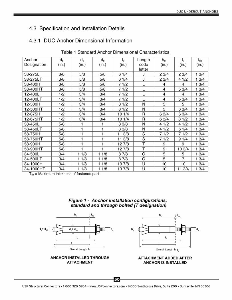
Figure 1 - Anchor installation configurations,
Overall Length Overall Length
ANCHOR INSTALLED THROUGHATTACHMENT
ATTACHMENT ADDED AFTERANCHOR IS INSTALLED
hef
ls
lb
ls
tfix t
fix
t t
ds+ d
bitd
bd
bd
s+ d
bit Do
h h
hef
standard and through bolted (T designation)
4.3 Specification and Installation Details
4.3.1 DUC Anchor Dimensional Information
Table 1 Standard Anchor Dimensional Characteristics Anchor Designation
db(in.)
ds(in.)
dc(in.)
lb(in.)
Length code letter
hef(in.)
ls(in.)
tfix (in.)
38-275L 3/8 5/8 5/8 6 1/4 J 2 3/4 2 3/4 1 3/4 38-275LT 3/8 5/8 5/8 6 1/4 J 2 3/4 4 1/2 1 3/4 38-400H 3/8 5/8 5/8 7 1/2 L 4 4 1 3/4 38-400HT 3/8 5/8 5/8 7 1/2 L 4 5 3/4 1 3/4 12-400L 1/2 3/4 3/4 7 1/2 L 4 4 1 3/4 12-400LT 1/2 3/4 3/4 7 1/2 L 4 5 3/4 1 3/4 12-500H 1/2 3/4 3/4 8 1/2 N 5 5 1 3/4 12-500HT 1/2 3/4 3/4 8 1/2 N 5 6 3/4 1 3/4 12-675H 1/2 3/4 3/4 10 1/4 R 6 3/4 6 3/4 1 3/4 12-675HT 1/2 3/4 3/4 10 1/4 R 6 3/4 8 1/2 1 3/4 58-450L 5/8 1 1 8 3/8 N 4 1/2 4 1/2 1 3/4 58-450LT 5/8 1 1 8 3/8 N 4 1/2 6 1/4 1 3/4 58-750H 5/8 1 1 11 3/8 S 7 1/2 7 1/2 1 3/4 58-750HT 5/8 1 1 11 3/8 S 7 1/2 9 1/4 1 3/4 58-900H 5/8 1 1 12 7/8 T 9 9 1 3/4 58-900HT 5/8 1 1 12 7/8 T 9 10 3/4 1 3/4 34-500L 3/4 1 1/8 1 1/8 8 7/8 O 5 5 1 3/4 34-500LT 3/4 1 1/8 1 1/8 8 7/8 O 5 7 1 3/4 34-1000H 3/4 1 1/8 1 1/8 13 7/8 U 10 10 1 3/4 34-1000HT 3/4 1 1/8 1 1/8 13 7/8 U 10 11 3/4 1 3/4
Tfix = Maximum thickness of fastened part
Figure 1 - Anchor installation configurations
51
USP Structural Connectors • 1-800-328-5934 • www.USPconnectors.com • 14305 Southcross Drive, Suite 200 • Burnsville, MN 55306
DUC UNDERCUT ANCHORS
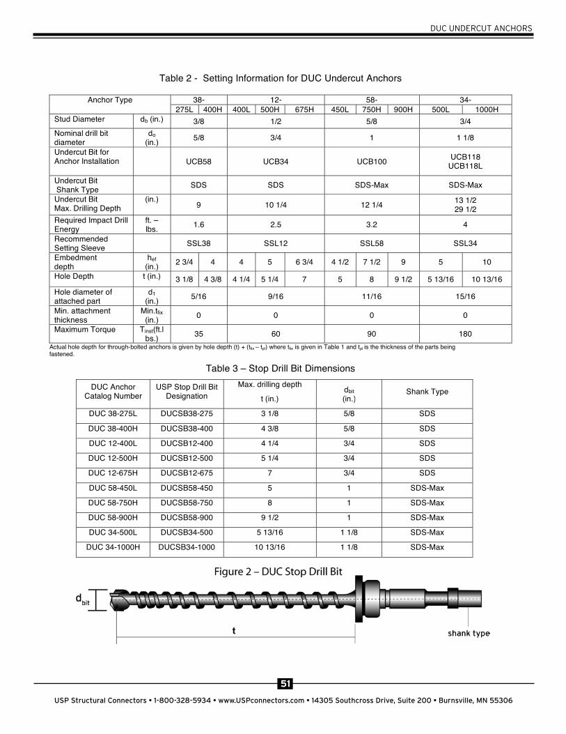
Table 2 - Setting Information for DUC Undercut Anchors
38- 12- 58- 34- Anchor Type 275L 400H 400L 500H 675H 450L 750H 900H 500L 1000H
Stud Diameter db (in.) 3/8 1/2 5/8 3/4 Nominal drill bit diameter
do(in.) 5/8 3/4 1 1 1/8
Undercut Bit for Anchor Installation UCB58 UCB34 UCB100 UCB118
UCB118L
Undercut Bit Shank Type SDS SDS SDS-Max SDS-Max
Undercut Bit Max. Drilling Depth
(in.) 9 10 1/4 12 1/4 13 1/2
29 1/2 Required Impact Drill Energy
ft. – lbs. 1.6 2.5 3.2 4
Recommended Setting Sleeve SSL38 SSL12 SSL58 SSL34
Embedment depth
hef(in.) 2 3/4 4 4 5 6 3/4 4 1/2 7 1/2 9 5 10
Hole Depth t (in.) 3 1/8 4 3/8 4 1/4 5 1/4 7 5 8 9 1/2 5 13/16 10 13/16 Hole diameter of attached part
d1(in.) 5/16 9/16 11/16 15/16
Min. attachment thickness
Min.tfix (in.) 0 0 0 0
Maximum Torque Tinst(ft.lbs.) 35 60 90 180
Actual hole depth for through-bolted anchors is given by hole depth (t) + (tfix – tpl) where tfix is given in Table 1 and tpl is the thickness of the parts being fastened.
Table 3 – Stop Drill Bit Dimensions
DUC Anchor Catalog Number
USP Stop Drill Bit Designation
Max. drilling depth
t (in.) dbit (in.)
Shank Type
DUC 38-275L DUCSB38-275 3 1/8 5/8 SDS
DUC 38-400H DUCSB38-400 4 3/8 5/8 SDS
DUC 12-400L DUCSB12-400 4 1/4 3/4 SDS
DUC 12-500H DUCSB12-500 5 1/4 3/4 SDS
DUC 12-675H DUCSB12-675 7 3/4 SDS
DUC 58-450L DUCSB58-450 5 1 SDS-Max
DUC 58-750H DUCSB58-750 8 1 SDS-Max
DUC 58-900H DUCSB58-900 9 1/2 1 SDS-Max
DUC 34-500L DUCSB34-500 5 13/16 1 1/8 SDS-Max
DUC 34-1000H DUCSB34-1000 10 13/16 1 1/8 SDS-Max
Figure 2 – DUC Stop Drill Bit

52
USP Structural Connectors • 1-800-328-5934 • www.USPconnectors.com • 14305 Southcross Drive, Suite 200 • Burnsville, MN 55306
DUC UNDERCUT ANCHORS
4.3.3 DUC Ductile Undercut Anchor Installation Procedures
4.4 1997 UBC Anchor Design 4.4.1 Introduction Design of the DUC Ductile undercut anchors in accordance with the 1997 UBC (Uniform
Building Code) is based primarily on evaluation of results of independent laboratory testing
conducted on the anchors in uncracked concrete in accordance ICBO/ICC ES AC 193.
These tests included static and seismic tests in tension and shear. See ICC ES ESR 1702 for additional information.
4.4.2 Allowable Stress Design in accordance with the 1997 UBC In the 1997 UBC, allowable stress design capacities of headed anchors in concrete are listed
in Table 19-D. This table was expanded from earlier versions in the UBC based on additional testing conducted on embedded bolts. This table lists tension and shear
capacities for 1/4” diameter through 1 1/4” diameter bolts with embedments of up to 9 inches.
Up to 50% reduction of the listed spacing and edge distance is permitted with an equal reduction in the allowable capacity. The tension capacities may be increased 100% when
special inspection is provided, and the allowable values may be increased 33 1/3% for short
duration of loads such as wind and seismic forces.
4.3.3 DUC Ductile Undercut Anchor Installation Procedures
Figure 3-UCB Undercut Bit (expanded).
53
USP Structural Connectors • 1-800-328-5934 • www.USPconnectors.com • 14305 Southcross Drive, Suite 200 • Burnsville, MN 55306
DUC UNDERCUT ANCHORS
4.4 2003/06 IBC Anchor Design (ACI 318-02/05, Appendix D)
4.4.1 Introduction
Design of the DUC Ductile Undercut Anchors in accordance with the 2003 and 2006 IBC is based on extensive testing and calculations conforming to state of the art standards. As described in Section 4.2.3 of this guide, the DUC anchor capacities listed in the following sections have been derived based on the requirements of ACI 318-05 Appendix D, ACI 355.2, and ICC ES AC 193. These tests include static and seismic tests, in tension and shear, in cracked and uncracked concrete, conducted in multiple concrete strengths. Additional testing included moving crack (opening and closing), group, spacing, edge, base thickness, and reduced setting effort tests. The result of this testing and evaluation is the basis for the design in the following sections.
4.4.2 Strength Design (LRFD) in accordance with the 2003/06 IBC
As noted previously, design strength of the DUC Undercut Anchors in accordance with the 2003/06 IBC is based primarily on the concepts found in ACI 318 Appendix D. The Appendix D method for concrete breakout design has been developed from the European Concrete Capacity Design (CCD) method, which was an adaptation of the Kappa ( ) Method, also from Europe. The concrete breakout method is based around a prism breakout angle of 35 degrees.
In accordance with Appendix D Section D.4.1.2, the strength of an anchor or group of anchors shall be based on the lowest design strength determined from all appropriate failure modes. Nn is the lowest design strength in tension, and Vn is the lowest design strength in shear. The information in Table 5 shall be used where required by Appendix D to complete anchor strength calculations in accordance with the code.
The strength reduction factor for anchors in concrete shall be in accordance with ACI 318 D.4.4 when using the load combinations found in section 9.2, or D.4.5 when using the load combinations found in Appendix C. Also, note that when anchor design includes seismic loads, the requirements of D.3.3 shall apply.
4.4.3 Allowable Stress Design in accordance with ACI 318-02/05
Allowable Strength Design (ASD) capacities for the DUC Ductile Undercut Anchors are derived by applying the appropriate factor to the limiting strength found when using the Strength Design Method (LRFD) calculations of the previous section. The ASD capacities for use in accordance with IBC Section 1605.3 are calculated using the following:
Tallowable, ASD = Nn/and
V allowable, ASD = Vn/ where:

54
USP Structural Connectors • 1-800-328-5934 • www.USPconnectors.com • 14305 Southcross Drive, Suite 200 • Burnsville, MN 55306
DUC UNDERCUT ANCHORS
4.4 2003/06 IBC Anchor Design (ACI 318-02/05, Appendix D)
4.4.1 Introduction
Design of the DUC Ductile Undercut Anchors in accordance with the 2003 and 2006 IBC is based on extensive testing and calculations conforming to state of the art standards. As described in Section 4.2.3 of this guide, the DUC anchor capacities listed in the following sections have been derived based on the requirements of ACI 318-05 Appendix D, ACI 355.2, and ICC ES AC 193. These tests include static and seismic tests, in tension and shear, in cracked and uncracked concrete, conducted in multiple concrete strengths. Additional testing included moving crack (opening and closing), group, spacing, edge, base thickness, and reduced setting effort tests. The result of this testing and evaluation is the basis for the design in the following sections.
4.4.2 Strength Design (LRFD) in accordance with the 2003/06 IBC
As noted previously, design strength of the DUC Undercut Anchors in accordance with the 2003/06 IBC is based primarily on the concepts found in ACI 318 Appendix D. The Appendix D method for concrete breakout design has been developed from the European Concrete Capacity Design (CCD) method, which was an adaptation of the Kappa ( ) Method, also from Europe. The concrete breakout method is based around a prism breakout angle of 35 degrees.
In accordance with Appendix D Section D.4.1.2, the strength of an anchor or group of anchors shall be based on the lowest design strength determined from all appropriate failure modes. Nn is the lowest design strength in tension, and Vn is the lowest design strength in shear. The information in Table 5 shall be used where required by Appendix D to complete anchor strength calculations in accordance with the code.
The strength reduction factor for anchors in concrete shall be in accordance with ACI 318 D.4.4 when using the load combinations found in section 9.2, or D.4.5 when using the load combinations found in Appendix C. Also, note that when anchor design includes seismic loads, the requirements of D.3.3 shall apply.
4.4.3 Allowable Stress Design in accordance with ACI 318-02/05
Allowable Strength Design (ASD) capacities for the DUC Ductile Undercut Anchors are derived by applying the appropriate factor to the limiting strength found when using the Strength Design Method (LRFD) calculations of the previous section. The ASD capacities for use in accordance with IBC Section 1605.3 are calculated using the following:
Tallowable, ASD = Nn/and
V allowable, ASD = Vn/ where:
Tallowable, ASD = Allowable tension load (lbf or kN)
Vallowable, ASD = Allowable shear load (lbf or kN)
Nn = Lowest design strength of an anchor or anchor group in tension as determined in accordance with ACI 318 Appendix D and 2006 IBC Section 1908.1.16.
Vn = Lowest design strength of an anchor or anchor group in shear as determined in accordance with ACI 318 Appendix D and 2006 IBC Section 1908.1.16.
= Conversion factor calculated as a weighted average of the load factors for the controlling load combination. In addition, shall include all applicable factors to account for non-ductile failure modes and required over-strength.
Interaction shall be calculated consistent with ACI 318 Appendix D Section D.7 as follows:
For shear loads V < 0.2 V allowable, ASD, the full allowable load in tension shall be permitted.
For tension loads T < 0.2 T allowable, ASD, the full allowable load in shear shall be permitted.
For all other cases: T / T allowable, ASD + V / Vallowable, ASD < 1.2
55
USP Structural Connectors • 1-800-328-5934 • www.USPconnectors.com • 14305 Southcross Drive, Suite 200 • Burnsville, MN 55306
DUC UNDERCUT ANCHORS
275L 400H 400L 500H 675H 450L 750H 900H 500L 1000H
Stud Diameter
Anchor O.D.
Min. Embedment
depth
Maximum Torque
Yield strength of anchor steel36 105 36 105 105 36 105 105 36 105
Ultimate strength of anchor steel58 125 58 125 125 58 125 125 58 125
Anchor Category1
Strength Reduction Factor for Tension Steel failure modes 2
Strength Reduction Factor for Shear Steel failure modes 2
2
2
Cond. A
Cond. B
Cond. A
Cond. B
Tensile stress Area
Effectiveness Factor Uncracked
Concrete
Effectiveness Factor Cracked Concrete3
Kc,uncr /Kc,cr
Steel Resistance - Static Tension
4494 9685 8225 17730 17730 13101 28247 28247 19371 41730
Steel Resistance-Static Shear
2247 4854 4112 8854 8854 6562 14112 14112 9685 20876
Steel Resistance-Sesimic Tension
4494 9685 8225 17730 17730 12292 26494 26494 16067 34607
Steel Resistance-Seismic Shear 2247 4854 4112 8854 8854 6562 14112 14112 9685 20876
Pullout Resistance cracked concrete 5
Pullout Resistance Seismic Tension
3/4
Anchor Designation
-43-85-21-83
8/5 2/1 8/3 ).ni( d
do 8/1 1 14/3 8/5 ).ni(
hef, min
(in.)2 3/4 4 4 5 6 3/4 4 1/2 7 1/2
fy (Ksi)
1724
9 5 10
Tinst 081090653).sbl.tf(
fut (Ksi)
1444
91
394
11113 ro ,2,1
0.75
131
930
0.65
22000
17730 357147428288811
0.75
0.7
Strength Reduction Factor for Tension Concrete failure modes
Strength Reduction Factor for Shear Concrete failure modes
Ase (in2 622.08141.05770.0)
00051005110009
0.334
0303
52.152.152.1
Kc,cr
SymbolDesign Parameter
Np,seismic (lbs)
Np,cr (lbs)
Vs,seismic (lbs)
Nsa,seismic (lbs)
Vs,static (lbs)
Nsa, static (lbs)
c,N
Kc,uncr (in-lb)
Axial Stiffness in the service loadrange in cracked concrete
min (103lb/in)
m (103lb/in)
Axial Stiffness in service load range uncracked concrete
min (103lb/in)
m (103lb/in)
max (103lb/in)
0.75
0.65
30
max (103lb/in)
1.25
30
42424242
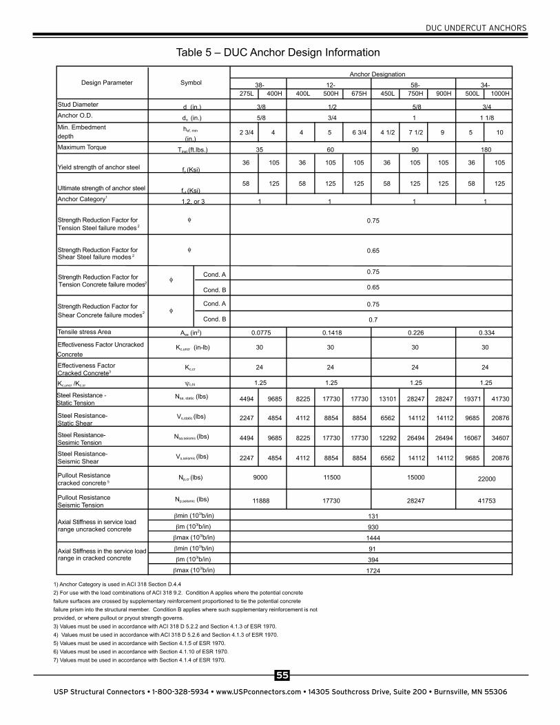
Table 5 – DUC Anchor Design Information
1) Anchor Category is used in ACI 318 Section D.4.4
2) For use with the load combinations of ACI 318 9.2. Condition A applies where the potential concrete
failure surfaces are crossed by supplementary reinforcement proportioned to tie the potential concrete
failure prism into the structural member. Condition B applies where such supplementary reinforcement is not
provided, or where pullout or pryout strength governs.
3) Values must be used in accordance with ACI 318 D 5.2.2 and Section 4.1.3 of ESR 1970.
4) Values must be used in accordance with ACI 318 D 5.2.6 and Section 4.1.3 of ESR 1970.
5) Values must be used in accordance with Section 4.1.5 of ESR 1970.
6) Values must be used in accordance with Section 4.1.10 of ESR 1970.
7) Values must be used in accordance with Section 4.1.4 of ESR 1970.

56
USP Structural Connectors • 1-800-328-5934 • www.USPconnectors.com • 14305 Southcross Drive, Suite 200 • Burnsville, MN 55306
DUC UNDERCUT ANCHORS
.
Table 6 – Spacing, Edge Distance and Concrete Thickness Requirements for DUC Undercut Anchors
Nominal Anchor Diameter
3/8 1/2 5/8 3/4 Design Parameter
Symbol 275L 400H 400L 500H 675H 450L 750H 900H 500L 100H
Anchor O.D. do
( in.)5/8 3/4 1 1 1/8
Min. Embedment depth
hef , min
( in.) 2 3/4 4 4 5 6 3/4 4 1/2 7 1/2 9 5 10
Dril l hole depth
t( in.)
3 1/8 4 3/8 4
1/4 5 1/4 7 5 8 9 1/2 5 13/16
1013/16
Minimum Concrete Thickness 1 Min. Concrete Thickness 1
hmin1 5 1/2 8 8 10 131/2
9 15 18 10 20
Crit ical edge distance
cac 4 1/8 6 6 7 1/2 101/8
6 3/4 111/4
131/2
7 1/2 15
Min. edge distance
cmin 2 1/4 3 1/4 3
1/4 4 5 3/8 3 5/8 6 7 1/4 4 8
Min. anchor spacing
smin 2 3/4 4 4 5 6 3/4 4 1/2 7 1/2 9 5 10
Minimum Concrete Thickness 2 Min. Concrete Thickness 2
hmin2 4 1/2 6 6 7 1/2 101/8
6 7/8 111/4
131/2
7 1/2 15
Crit ical edge distance
ccr 4 1/8 6 6 7 1/2 101/8
6 3/4 111/4
131/2
7 1/2 15
Crit ical corner edge distance
cac 5 1/2 103/8
93/16
13201/4
97/16
21 27 10 1/2 30
Min. edge distance
cmin 2 1/4 3 1/4 3
1/4 4 5 3/8 3 5/8 6 7 1/4 4 8
Min. anchor spacing
smin 2 3/4 4 4 5 6 3/4 4 1/2 7 1/2 9 5 10
57
USP Structural Connectors • 1-800-328-5934 • www.USPconnectors.com • 14305 Southcross Drive, Suite 200 • Burnsville, MN 55306
DUC UNDERCUT ANCHORS
Crit ical edge
distance ccr 4 1/8 6 6 7 1/2
10
1/8 6 3/4
11
1/4
13
1/2 7 1/2 15
Crit ical corner
edge distance cac 5 1/2
10
3/8
9
3/16 13
20
1/4
9
7/16 21 27 10 1/2 30
Min. edge
distance cmin 2 1/4 3 1/4
3
1/4 4 5 3/8 3 5/8 6 7 1/4 4 8
Min. anchor
spacing smin 2 3/4 4 4 5 6 3/4 4 1/2 7 1/2 9 5 10
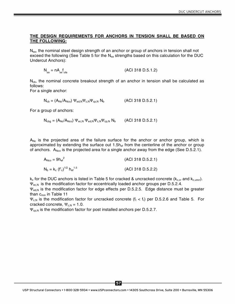
THE DESIGN REQUIREMENTS FOR ANCHORS IN TENSION SHALL BE BASED ON THE FOLLOWING:
Nsa, the nominal steel design strength of an anchor or group of anchors in tension shall not exceed the following (See Table 5 for the Nsa strengths based on this calculation for the DUC Undercut Anchors):
Nsa
= nAse
futa
(ACI 318 D.5.1.2)
Ncb, the nominal concrete breakout strength of an anchor in tension shall be calculated as follows: For a single anchor:
Ncb = (ANc/ANco) ed,N c,N cp,N Nb (ACI 318 D.5.2.1)
For a group of anchors:
Ncbg = (ANc/ANco) ec,N ed,N c,N cp,N Nb (ACI 318 D.5.2.1)
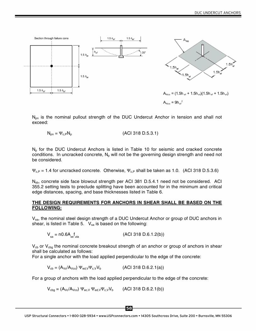
ANc is the projected area of the failure surface for the anchor or anchor group, which is approximated by extending the surface out 1.5hef from the centerline of the anchor or group of anchors. ANco is the projected area for a single anchor away from the edge (See D.5.2.1).
ANco = 9hef2 (ACI 318 D.5.2.1)
Nb = kc (f’c)1/2 hef
1.5 (ACI 318 D.5.2.2)
kc for the DUC anchors is listed in Table 5 for cracked & uncracked concrete (kc,cr and kc,uncr). ec,N is the modification factor for eccentrically loaded anchor groups per D.5.2.4.ed,N is the modification factor for edge effects per D.5.2.5. Edge distance must be greater
than cmin in Table 11 c,N is the modification factor for uncracked concrete (ft < fr) per D.5.2.6 and Table 5. For
cracked concrete, c,N = 1.0. cp,N is the modification factor for post installed anchors per D.5.2.7.
58
USP Structural Connectors • 1-800-328-5934 • www.USPconnectors.com • 14305 Southcross Drive, Suite 200 • Burnsville, MN 55306
DUC UNDERCUT ANCHORS
Npn is the nominal pullout strength of the DUC Undercut Anchor in tension and shall not exceed:
Npn = c,PNp (ACI 318 D.5.3.1)
Np for the DUC Undercut Anchors is listed in Table 10 for seismic and cracked concrete conditions. In uncracked concrete, Np will not be the governing design strength and need not be considered.
c,P = 1.4 for uncracked concrete. Otherwise, c,P shall be taken as 1.0. (ACI 318 D.5.3.6)
Nsb, concrete side face blowout strength per ACI 381 D.5.4.1 need not be considered. ACI 355.2 setting tests to preclude splitting have been accounted for in the minimum and critical edge distances, spacing, and base thicknesses listed in Table 6.
THE DESIGN REQUIREMENTS FOR ANCHORS IN SHEAR SHALL BE BASED ON THE FOLLOWING:
Vsa, the nominal steel design strength of a DUC Undercut Anchor or group of DUC anchors in shear, is listed in Table 5. Vsa is based on the following:
Vsa
= n0.6Ase
futa
(ACI 318 D.6.1.2(b))
Vcb or Vcbg the nominal concrete breakout strength of an anchor or group of anchors in shear shall be calculated as follows: For a single anchor with the load applied perpendicular to the edge of the concrete:
Vcb = (AVc/AVco) ed,V c,VVb (ACI 318 D.6.2.1(a))
For a group of anchors with the load applied perpendicular to the edge of the concrete:
Vcbg = (AVc/AVco) ec,V ed,V c,VVb (ACI 318 D.6.2.1(b))
ANco = (1.5h ef + 1.5h ef)(1.5h ef + 1.5h ef) ANco = 9hef
2

59
USP Structural Connectors • 1-800-328-5934 • www.USPconnectors.com • 14305 Southcross Drive, Suite 200 • Burnsville, MN 55306
DUC UNDERCUT ANCHORS
For a shear force parallel to an edge, Vcb and Vcbg shall be twice the value calculated above respectively, with ed,V = 1.0.
AVc is the projected area of the failure surface on the side of a concrete member in the direction of the load for the anchor or anchor group. AVc shall be the area of the base of a truncated half pyramid projected on the side face of the member (See D.6.2.1). AVco is the projected area for a single anchor in a deep member away from the edge. AVco shall be the area of the base of a half pyramid with a side length parallel to the edge of 3ca1 and a depth of 1.5ca1 (See D.6.2.1)
AVco = 4.5ca12 (ACI 318 D.6.2.1)
Vb is the basic concrete breakout strength of a single anchor in cracked concrete.
Vb = 7(l/do)0.2(do)1/2 (f’c)1/2 c1.5 (ACI 318 D.6.2.2)
ec,V is the modification factor for eccentrically loaded anchor groups per D.6.2.5.ed,V is the modification factor for edge effects per D.6.2.6. Edge distance must be greater
than cmin in Table 6. c,V is the modification factor for cracked/uncracked concrete and supplementary
reinforcement per D.6.2.7. For cracked concrete, c,V = 1.0.
Vcp is the nominal pryout strength of an anchor in shear and shall not exceed:
Vcp = kcp Ncb (ACI 318 D.6.3.1) where kcp = 1.0 for hef < 2.5 in. kcp = 2.0 for hef > 2.5 in.
For combined loads, the following may be used when an anchor or group of anchors is simultaneously subjected to both shear and tension loading:
If Vua < 0.2 Vn, then full strength in tension shall be permitted: Nn > Nua.If Nua < 0.2 Nn, then full strength in shear shall be permitted: Vn > Vua.If Vua > 0.2 Vn and Nu > 0.2 Nn, then:
(Nua/ Nn) + (Vua/ Vn) < 1.2 (ACI 318 D.7.3)
ACI 355.2 setting tests to preclude splitting have been accounted for in the minimum and critical edge distances, spacing, and base thicknesses listed in Table 6.
60
USP Structural Connectors • 1-800-328-5934 • www.USPconnectors.com • 14305 Southcross Drive, Suite 200 • Burnsville, MN 55306
DUC UNDERCUT ANCHORS
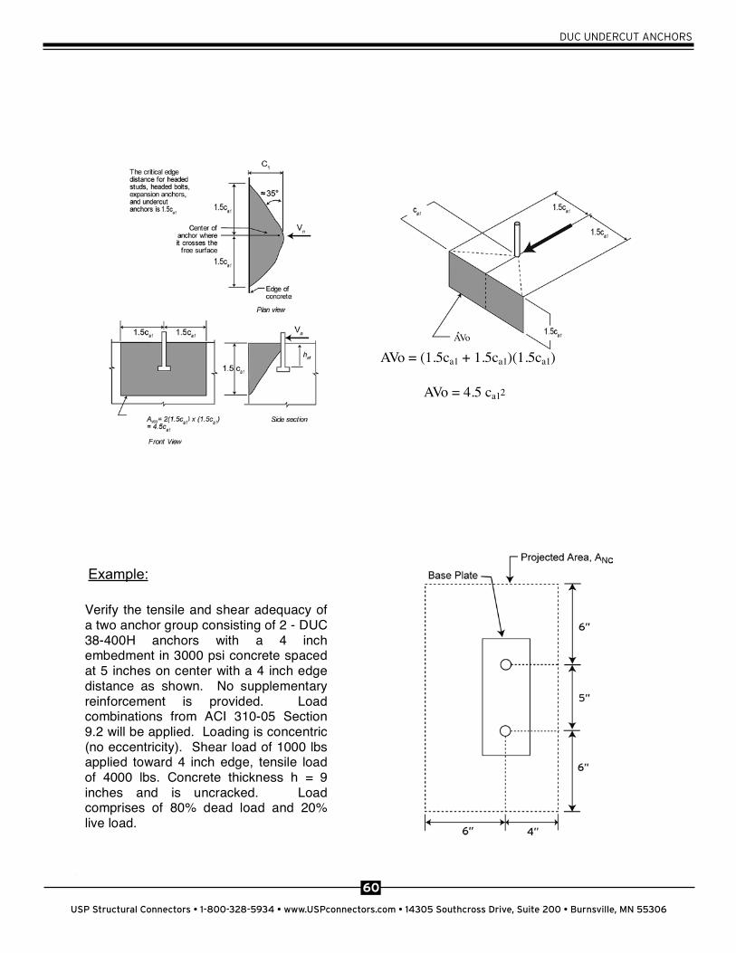
AVo = (1.5ca1 + 1.5ca1)(1.5ca1)
AVo = 4.5 ca1 2
6
Calculation ACI 318-05Appendix D
Section
ESR 1970Section
Steel strength in tension: Nsa = nAsefuta = (2)(.0775)(125000) = 19375 lb D.5.1.2 Table 5
Steel capacity in tension: Nsa = (0.75)(19375) = 14531 lb ( for steel tension failure
modes) D.4.4 Table 5
Concrete breakout in tension: Ncbg = (ANc/ANco) ec,N ed,N c,N cp,N Nb
ec,N =1.0 (no eccentricity) ed,N = 0.7 + 0.3(c/1.5hef) = 0.7 + 0.3(4/1.5(4)) = 0.90 c,N = 1.25 (uncracked concrete) cp,N = (1.5)(4)/6 = 1.0
ANo = 9hef2 = (9)(4)2 = 144 in2
AN = (1.5hef + s + 1.5hef )(1.5 hef + c) = (6+5+6)(6+4) = 170 in2
kc,uncr = 30 Nb = kc,uncr (f’c)1/2 hef
1.5 = (30)(3000)1/2(4)1.5 = 13145 lb Ncbg = (170/144)(1.0)(0.90)(1.25)(1.0)(13145) = 17458 lb
Ncbg = (0.65)(17458) = 11,348 lb ( for concrete failure mode, no supplementary reinforcement)
D.5.2.1 D.5.2.4 D.5.2.5 D.5.2.6 D.5.2.7 D.5.2.1
RD.5.2.1 D.5.2.2 D.5.2.2
D.4.4
Table 5
Table 5
Table 5
Concrete pullout in tension: Npn = c,PNp N/A – pullout does not govern in uncrackedconcrete.
D.5.3.1 Table 5
Controlling tensile strength Nn = Ncbg = 11348 lb for the 2
Verify the tensile and shear adequacy ofa two anchor group consisting of 2 - DUC38-400H anchors with a 4 inchembedment in 3000 psi concrete spacedat 5 inches on center with a 4 inch edgedistance as shown. No supplementaryreinforcement is provided. Loadcombinations from ACI 310-05 Section9.2 will be applied. Loading is concentric(no eccentricity). Shear load of 1000 lbsapplied toward 4 inch edge, tensile loadof 4000 lbs. Concrete thickness h = 9inches and is uncracked. Loadcomprises of 80% dead load and 20%live load.
Example:
AVo

61
USP Structural Connectors • 1-800-328-5934 • www.USPconnectors.com • 14305 Southcross Drive, Suite 200 • Burnsville, MN 55306
DUC UNDERCUT ANCHORS
6
Calculation ACI 318-05Appendix D
Section
ESR 1970Section
Steel strength in tension: Nsa = nAsefuta = (2)(.0775)(125000) = 19375 lb D.5.1.2 Table 5
Steel capacity in tension: Nsa = (0.75)(19375) = 14531 lb ( for steel tension failure
modes) D.4.4 Table 5
Concrete breakout in tension: Ncbg = (ANc/ANco) ec,N ed,N c,N cp,N Nb
ec,N =1.0 (no eccentricity) ed,N = 0.7 + 0.3(c/1.5hef) = 0.7 + 0.3(4/1.5(4)) = 0.90 c,N = 1.25 (uncracked concrete) cp,N = (1.5)(4)/6 = 1.0
ANo = 9hef2 = (9)(4)2 = 144 in2
AN = (1.5hef + s + 1.5hef )(1.5 hef + c) = (6+5+6)(6+4) = 170 in2
kc,uncr = 30 Nb = kc,uncr (f’c)1/2 hef
1.5 = (30)(3000)1/2(4)1.5 = 13145 lb Ncbg = (170/144)(1.0)(0.90)(1.25)(1.0)(13145) = 17458 lb
Ncbg = (0.65)(17458) = 11,348 lb ( for concrete failure mode, no supplementary reinforcement)
D.5.2.1 D.5.2.4 D.5.2.5 D.5.2.6 D.5.2.7 D.5.2.1
RD.5.2.1 D.5.2.2 D.5.2.2
D.4.4
Table 5
Table 5
Table 5
Concrete pullout in tension: Npn = c,PNp N/A – pullout does not govern in uncrackedconcrete.
D.5.3.1 Table 5
Controlling tensile strength Nn = Ncbg = 11348 lb for the 2
Verify the tensile and shear adequacy ofa two anchor group consisting of 2 - DUC38-400H anchors with a 4 inchembedment in 3000 psi concrete spacedat 5 inches on center with a 4 inch edgedistance as shown. No supplementaryreinforcement is provided. Loadcombinations from ACI 310-05 Section9.2 will be applied. Loading is concentric(no eccentricity). Shear load of 1000 lbsapplied toward 4 inch edge, tensile loadof 4000 lbs. Concrete thickness h = 9inches and is uncracked. Loadcomprises of 80% dead load and 20%live load.
anchor group
Steel strength in shear: nVsa = (2)(4854) = 9708 lb (loaded through anchor stud only,non-T anchor)
Table 5
Steel capacity in shear: Vsa = (0.65)(9708) = 6310 lb ( for ductile steel shearfailure modes)
Table 5
Concrete breakout in shear: Vcbg = (AVc/AVco) ec,V ed,V c,VVb
ec,V = 1.0 (no eccentricity) ed,V = 1.0
c,V = 1.4 (uncracked concrete) AVco = 4.5ca1
2 = (4.5)(4)2 = 72 in2
AVc = (1.5c a1 + s + 1.5c a1)(1.5c a1) = (6 + 6 + 6)(6) = 108 in2
Vb = 7(l/do)0.2(do)1/2 (f’c)1/2 c a11.5
l = lesser of hef or 8(do) = (8)(3/8) = 3” Note that for through bolted anchors (T), do = ds (sleeve dia) Vb = 7(3/(3/8))0.2(3/8)1/2 (3000)1/2 (4)1.5 = 2847 lb Vcbg = (108/72)(1.0)(1.0)(1.4)(2847) = 5979 lb
Vcbg = (0.70)(5979) = 4185 lb ( for concrete failure mode, no supplementary reinforcement)
D.6.2.1(b) D.6.2.5 D.6.2.6 D.6.2.7 D.6.2.1
D.6.2.2 D.6.2.2
Table 5 Concrete Pryout: Vcp = kcp Ncbg = (2.0)(17458) = 34916 lb
Vcpg = (0.70)(34916) = 24441 lbD.6.3.1
Controlling shear strength Vn = Vcbg = 4185 lb for the 2 anchorgroup
Combined loading: Given 80% D + 20% L loading, ACI 318-05, 9.2, 9-2 governs. U = 1.2D + 1.6L. Nua = (1.2)(.8)(4000) + (1.6)(.2)(4000) = 5120 lb Vua = (1.2)(.8)(1000) + (1.6)(.2)(1000) = 1280 lb Verify that the applied factored loads Nua and Vua comply with thefollowing: Nua / Nn + Vua/ Vn < 1.2 = 5120/11348 + 1280/4185 = 0.76 <1.2 ok
D.7.3
Or, for ASD, determine based on ACI 318-05 9.2 load combinations.Given 80% D + 20%L loading, 9-2 governs. U = 1.2D + 1.6L.
= 1.2(0.8) + 1.6(0.2) = 1.28
9.2.1 4.2
Allowable tensile strength: Nallowable ASD = n / = (11348)/1.28 = 8865 lb for the 2 anchor group
4.2

62
USP Structural Connectors • 1-800-328-5934 • www.USPconnectors.com • 14305 Southcross Drive, Suite 200 • Burnsville, MN 55306
DUC UNDERCUT ANCHORS
anchor group
Steel strength in shear: nVsa = (2)(4854) = 9708 lb (loaded through anchor stud only,non-T anchor)
Table 5
Steel capacity in shear: Vsa = (0.65)(9708) = 6310 lb ( for ductile steel shearfailure modes)
Table 5
Concrete breakout in shear: Vcbg = (AVc/AVco) ec,V ed,V c,VVb
ec,V = 1.0 (no eccentricity) ed,V = 1.0
c,V = 1.4 (uncracked concrete) AVco = 4.5ca1
2 = (4.5)(4)2 = 72 in2
AVc = (1.5c a1 + s + 1.5c a1)(1.5c a1) = (6 + 6 + 6)(6) = 108 in2
Vb = 7(l/do)0.2(do)1/2 (f’c)1/2 c a11.5
l = lesser of hef or 8(do) = (8)(3/8) = 3” Note that for through bolted anchors (T), do = ds (sleeve dia) Vb = 7(3/(3/8))0.2(3/8)1/2 (3000)1/2 (4)1.5 = 2847 lb Vcbg = (108/72)(1.0)(1.0)(1.4)(2847) = 5979 lb
Vcbg = (0.70)(5979) = 4185 lb ( for concrete failure mode, no supplementary reinforcement)
D.6.2.1(b) D.6.2.5 D.6.2.6 D.6.2.7 D.6.2.1
D.6.2.2 D.6.2.2
Table 5 Concrete Pryout: Vcp = kcp Ncbg = (2.0)(17458) = 34916 lb
Vcpg = (0.70)(34916) = 24441 lbD.6.3.1
Controlling shear strength Vn = Vcbg = 4185 lb for the 2 anchorgroup
Combined loading: Given 80% D + 20% L loading, ACI 318-05, 9.2, 9-2 governs. U = 1.2D + 1.6L. Nua = (1.2)(.8)(4000) + (1.6)(.2)(4000) = 5120 lb Vua = (1.2)(.8)(1000) + (1.6)(.2)(1000) = 1280 lb Verify that the applied factored loads Nua and Vua comply with thefollowing: Nua / Nn + Vua/ Vn < 1.2 = 5120/11348 + 1280/4185 = 0.76 <1.2 ok
D.7.3
Or, for ASD, determine based on ACI 318-05 9.2 load combinations.Given 80% D + 20%L loading, 9-2 governs. U = 1.2D + 1.6L.
= 1.2(0.8) + 1.6(0.2) = 1.28
9.2.1 4.2
Allowable tensile strength: Nallowable ASD = n / = (11348)/1.28 = 8865 lb for the 2 anchor group
4.2
Allowable shear strength: Vallowable ASD = Vn / = (4185)/1.28 = 3270 lb for the 2 anchor group
4.2
Interaction: T/Tallowable ASD = V/Vallowable ASD < 1.2 = (4000/8865) + (1000/3270) = 0.76 < 1.2 ok
4.2