
Dubai metro challenge for a fast track construction - · PDF fileDubai metro challenge for a...
6
Tailor Made Concrete Structures – Walraven & Stoelhorst (eds) © 2008Taylor & Francis Group, London, ISBN 978-0-415-47535-8 Dubai metro challenge for a fast track construction Y. Gauthier, S. Montens, P.Arnaud &T. Paineau Systra ABSTRACT: Building a transportation infrastructure is a critical challenge for the fast growing city of Dubai. Both elevated and underground structures of the two first Metro lines of Dubai have been designed to be cost and time efficient. On the elevated section, the Railway viaduct is designed to be built extensively by precast techniques. The time efficient proven technique of precast segmental construction is implemented. The elevated station concept is in line with the standardization of the viaduct design and construction. At the end, the overall success of a speedy and timely construction depends on the quality of the planning: interface with Third Parties Projects, Utilities, resources, design freeze, quick decision process, are as usual, critical parameters. 1 INTRODUCTION In 2003, the Road and Transport Authority of Dubai awarded a contract for the Preliminary Design of the Red Line and Green line of the Dubai Metro to SYS- TRA. SYSTRA has prepared a concept for the System (Civil Works and Rail System) and then has developed a 30% Design to establish the Dubai Metro Tender documentation. Since July 2005, SYSTRA in joint venture with Parsons was awarded the Project Manage- ment and Consultancy Services, Contract that include the verification of the design, the supervision of the Civil Works construction and Rail System installa- tion, supervision of the tests, preparation of Operation, assistance during the guarantee period. 2 DUBAI CONTEXT The Dubai population should considerably increase over the next years. The number of residents is pre- dicted to grow from 1.5 million who currently live in the city to more than five million by 2020. As a result, road congestion could lead to severe economic losses. The RTA announced in November 2007 that Dubai’s transport infrastructure would be dramatically improved with a range of road, rail and marine projects estimated around $22 billion to be completed by 2020. The RailAgency of the RTA has announced so far plans for four Metro lines – red, green, purple and blue. In this context, speed of construction is a key parameter of Dubai success. There are many aspects to the speed of construction and we can list: Client (RTA): fast track decision process, commitment to freeze the design Consultant (SYSTRA): consideration of construction speed criteria in the conceptual design, proposal of adequate construction methods Contractor: resources, procurement, management of design and construction interfaces. In this paper, we would like to review the Systra early conceptual choices for the Civil Works that were aimed at increasing the speed of construction. 3 BRIEF DESCRIPTION OF DUBAI METRO SYSTEM The Dubai Metro will be a fully automated and driver- less system. The Red and Green Line Dubai Metro lines are 75kms long of which 13km are underground and 62km are elevated. Red Line Elevated 44.1 km 24 stations Underground ∗ 4.7 km 4 stations At Grade 3.3 km 1 station Total Red Line 52.1 km 29 stations ∗ with 2 transfer stations. Green Line Elevated 14.6 km 12 stations Underground ∗ 7.9 km 6 stations Total Red Line 22.5 km 18 stations ∗ with 2 transfer stations. 977
Transcript of Dubai metro challenge for a fast track construction - · PDF fileDubai metro challenge for a...

Tailor Made Concrete Structures – Walraven & Stoelhorst (eds)© 2008 Taylor & Francis Group, London, ISBN 978-0-415-47535-8
Dubai metro challenge for a fast track construction
Y. Gauthier, S. Montens, P. Arnaud & T. PaineauSystra
ABSTRACT: Building a transportation infrastructure is a critical challenge for the fast growing city of Dubai.Both elevated and underground structures of the two first Metro lines of Dubai have been designed to be costand time efficient. On the elevated section, the Railway viaduct is designed to be built extensively by precasttechniques. The time efficient proven technique of precast segmental construction is implemented. The elevatedstation concept is in line with the standardization of the viaduct design and construction. At the end, the overallsuccess of a speedy and timely construction depends on the quality of the planning: interface with Third PartiesProjects, Utilities, resources, design freeze, quick decision process, are as usual, critical parameters.
1 INTRODUCTION
In 2003, the Road and Transport Authority of Dubaiawarded a contract for the Preliminary Design of theRed Line and Green line of the Dubai Metro to SYS-TRA. SYSTRA has prepared a concept for the System(Civil Works and Rail System) and then has developeda 30% Design to establish the Dubai Metro Tenderdocumentation. Since July 2005, SYSTRA in jointventure with Parsons was awarded the Project Manage-ment and Consultancy Services, Contract that includethe verification of the design, the supervision of theCivil Works construction and Rail System installa-tion, supervision of the tests, preparation of Operation,assistance during the guarantee period.
2 DUBAI CONTEXT
The Dubai population should considerably increaseover the next years. The number of residents is pre-dicted to grow from 1.5 million who currently livein the city to more than five million by 2020. As aresult, road congestion could lead to severe economiclosses. The RTA announced in November 2007 thatDubai’s transport infrastructure would be dramaticallyimproved with a range of road, rail and marine projectsestimated around $22 billion to be completed by 2020.The RailAgency of the RTA has announced so far plansfor four Metro lines – red, green, purple and blue.
In this context, speed of construction is a keyparameter of Dubai success.
There are many aspects to the speed of constructionand we can list:
Client (RTA): fast track decision process, commitmentto freeze the design
Consultant (SYSTRA): consideration of constructionspeed criteria in the conceptual design, proposal ofadequate construction methods
Contractor: resources, procurement, management ofdesign and construction interfaces.
In this paper, we would like to review the Systraearly conceptual choices for the Civil Works that wereaimed at increasing the speed of construction.
3 BRIEF DESCRIPTION OF DUBAI METROSYSTEM
The Dubai Metro will be a fully automated and driver-less system. The Red and Green Line Dubai Metrolines are 75kms long of which 13km are undergroundand 62km are elevated.
Red LineElevated 44.1 km 24 stationsUnderground∗ 4.7 km 4 stationsAt Grade 3.3 km 1 stationTotal Red Line 52.1 km 29 stations
∗ with 2 transfer stations.
Green LineElevated 14.6 km 12 stationsUnderground∗ 7.9 km 6 stationsTotal Red Line 22.5 km 18 stations
∗ with 2 transfer stations.
977

The maximal capacity of the Red Line is reachedwith 106 trains and a 90s headway correspondingto 25720 persons per hour and per direction (with4 persons/m2).
The maximal capacity of the Green Line is reachedwith 64 trains and a 90s headway correspondingto 25720 persons per hour and per direction (with4 persons/m2).
4 VIADUCT – SUPERSTRUCTURES
SYSTRA proposed an innovative design based on theU-viaduct concept.
Over the past 6 years SYSTRA fine tuned this con-cept in several metro projects (Delhi Line 3, SantiagoLine 4 among others).
The U-viaduct offers several advantages both interms of insertion into the city and in terms of cost.
• The rail level can be lowered due to the minimumdistance between the rail and the bottom of the deck.This results in savings for the design of the founda-tions (lever arm of horizontal forces reduced) andof the stations.
• The visual impact is reduced: no extra anti derail-ment barrier is required, noise barrier is integratedand the top flanges do provide emergency walkways(at coach floor level) all along the line.
• The open shape is particularly convenient for pre-casting (no collapsible inner form required) andfor erection (workers are safely standing inside theU-girder).
5 VIADUCT – STANDARDISATION
To match the very tight time schedule (the Design andBuild contract was finalized in July 2005, and revenueservice is to start on 09/09/2009 for the 52 km of theRed Line and on 21/03/2010 for the 22 km of GreenLine) SYSTRA proposed a limited number of versatilestructures types that could accommodate all the spanconfigurations.
5.1 Span distribution on Red line
• Simple spans up to 36m (typical span being 32 m);
• Twin-spans from 36 m to 44 m: these structures areerected as 2nos simple spans. Subsequently (awayfrom the launching girders critical path) a concretestitch is cast between the 2 spans and continuitypost-tensioning is stressed;
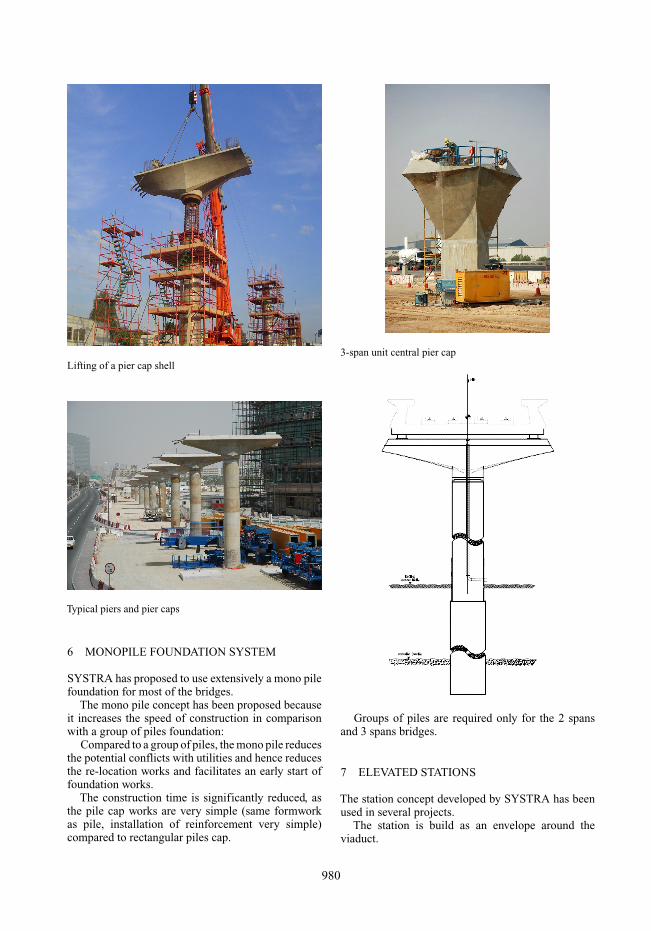
• 3-span units up to 72 m: these long span bridges arerequired at most of the road interchanges crossed bythe alignment. They feature a variable depth deckresulting from the combination of a U-girder and abox-girder. The depth of the deck at the end spansis identical to the depth of the adjacent spans thusproviding a perfectly smooth transition. The bridgeis erected by the balanced cantilever method.
• Continuous units in stations: the continuity iscalled by the very limited movements of the spansrequested by the platform screen doors. As for thetwin span units the continuity is implemented outof the launching girders critical path.
• 3-track stations (Nakheel and Rashidiya): some ofthe spans are cast in situ whereas the single trackspans are made of precast segments.
978
The choice for precasting techniques meets thespeed criteria: casting operations starts very early inthe construction schedule and hence it reduces theoverall construction duration.
The deck segments are manufactured in a 45 ha pre-casting yard located in Jebel Ali (5 km away from thesouth portion of the Red Line).
16500 segments are to be cast (75% for the RedLine and 25% for the Green line) using 66 moulds(long lines and cells). The daily production is 35 to40 segments which require ∼ 170 tons of reinforce-ment and ∼ 800 m3 of double mix concrete producedby 2 dedicated batching plants. Casting operations arescheduled to last 2 years.
The casting yard is served by 11 gantry cranes and8 tower cranes.
The segment weight ranges from 49 t for the mosttypical to 88 t for some segments of the 3-span unit.The segments are transported to site by dedicatedtrailers (maximum segment length is 4 m).
The spans are erected by several methods:
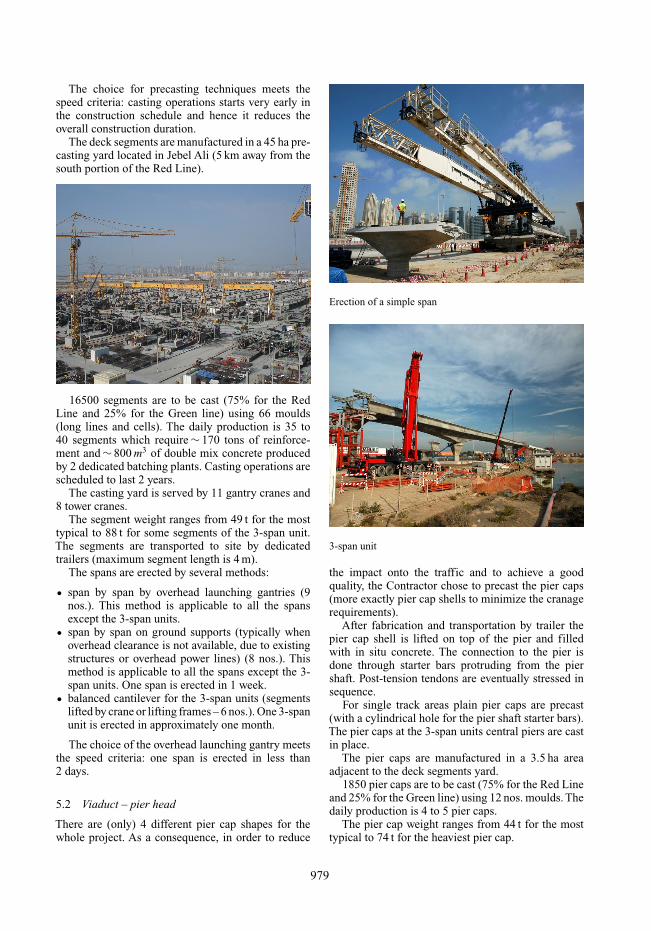
• span by span by overhead launching gantries (9nos.). This method is applicable to all the spansexcept the 3-span units.
• span by span on ground supports (typically whenoverhead clearance is not available, due to existingstructures or overhead power lines) (8 nos.). Thismethod is applicable to all the spans except the 3-span units. One span is erected in 1 week.
• balanced cantilever for the 3-span units (segmentslifted by crane or lifting frames – 6 nos.). One 3-spanunit is erected in approximately one month.
The choice of the overhead launching gantry meetsthe speed criteria: one span is erected in less than2 days.
5.2 Viaduct – pier head
There are (only) 4 different pier cap shapes for thewhole project. As a consequence, in order to reduce
Erection of a simple span
3-span unit
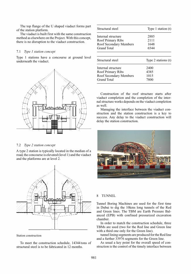
the impact onto the traffic and to achieve a goodquality, the Contractor chose to precast the pier caps(more exactly pier cap shells to minimize the cranagerequirements).
After fabrication and transportation by trailer thepier cap shell is lifted on top of the pier and filledwith in situ concrete. The connection to the pier isdone through starter bars protruding from the piershaft. Post-tension tendons are eventually stressed insequence.
For single track areas plain pier caps are precast(with a cylindrical hole for the pier shaft starter bars).The pier caps at the 3-span units central piers are castin place.
The pier caps are manufactured in a 3.5 ha areaadjacent to the deck segments yard.
1850 pier caps are to be cast (75% for the Red Lineand 25% for the Green line) using 12 nos. moulds. Thedaily production is 4 to 5 pier caps.
The pier cap weight ranges from 44 t for the mosttypical to 74 t for the heaviest pier cap.
979
Lifting of a pier cap shell
Typical piers and pier caps
6 MONOPILE FOUNDATION SYSTEM
SYSTRA has proposed to use extensively a mono pilefoundation for most of the bridges.
The mono pile concept has been proposed becauseit increases the speed of construction in comparisonwith a group of piles foundation:
Compared to a group of piles, the mono pile reducesthe potential conflicts with utilities and hence reducesthe re-location works and facilitates an early start offoundation works.
The construction time is significantly reduced, asthe pile cap works are very simple (same formworkas pile, installation of reinforcement very simple)compared to rectangular piles cap.
3-span unit central pier cap
Groups of piles are required only for the 2 spansand 3 spans bridges.
7 ELEVATED STATIONS
The station concept developed by SYSTRA has beenused in several projects.
The station is build as an envelope around theviaduct.
980
The top flange of the U shaped viaduct forms partof the station platform.
The viaduct is built first with the same constructionmethod as elsewhere on the Project. With this concept,there is no disruption to the viaduct construction.
7.1 Type 1 station concept
Type 1 stations have a concourse at ground levelunderneath the viaduct.
7.2 Type 2 station concept
A type 2 station is typically located in the median of aroad, the concourse is elevated (level 1) and the viaductand the platforms are at level 2.
Station construction
To meet the construction schedule, 14344 tons ofstructural steel is to be fabricated in 12 months.
Structural steel Type 1 station (t)
Internal structure 2885Roof Primary Ribs 2111Roof Secondary Members 1648Grand Total 6544
Structural steel Type 2 stations (t)
Internal structure 2400Roof Primary Ribs 4385Roof Secondary Members 1015Grand Total 7800
Construction of the roof structure starts afterviaduct completion and the completion of the inter-nal structure works depends on the viaduct completionas well.
Managing the interface between the viaduct con-struction and the station construction is a key tosuccess. Any delay to the viaduct construction willdelay the station construction.
8 TUNNEL
Tunnel Boring Machines are used for the first timein Dubai to dig the 10kms long tunnels of the Redand Green lines. The TBM are Earth Pressure Bal-anced (EPB) with confined pressurized excavationchamber.
In order to match the construction schedule, threeTBMs are used (two for the Red line and Green linewith a third one only for the Green line).
tunnel lining segments are produced for the Red lineand a further 33976 segments for the Green line.
As usual a key point for the overall speed of con-struction is the control of the timely interface between
981

underground stations construction and break in/out ofthe TBM.
9 UNDERGROUND STATIONS
For the 10 underground stations of the Red and Greenline, the top down technique has been selected tominimize the disruption to roads surface traffic.
10 CONCLUSION
Red and Green line are mainly elevated. The SYS-TRA concepts for the viaduct and elevated stationsare cost efficient and time effective. These conceptshave been validated as they have not been amended bythe Contractor in the context of the tight Dubai Metroconstruction schedule.
982


![Dubai Metro: building the world s longest driverless metro1].pdf · 116 Civil Engineering Volume 165 Issue CE3 August 2012 Dubai Metro: building the world s longest driverless metro](https://static.fdocuments.in/doc/165x107/5a7a7a257f8b9a2d788bc8c7/dubai-metro-building-the-world-s-longest-driverless-1pdf116-civil-engineering.jpg)
