Dual Sensing Digital Instructions - REHAU North America thermostat (Art. No. 236487-001) comes...
12
Construction Automotive Industry www.rehau.com DUAL SENSING DIGITAL THERMOSTAT PRODUCT INSTRUCTIONS
-
Upload
nguyenkhanh -
Category
Documents
-
view
214 -
download
0
Transcript of Dual Sensing Digital Instructions - REHAU North America thermostat (Art. No. 236487-001) comes...
ConstructionAutomotive
Industry
www.rehau.com
DUAL SENSING DIGITAL THERMOSTAT PRODUCT INSTRUCTIONS
2
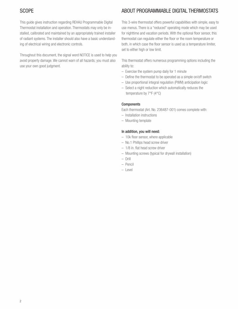
SCOPE
This guide gives instruction regarding REHAU Programmable Digital Thermostat installation and operation. Thermostats may only be in-stalled, calibrated and maintained by an appropriately trained installer of radiant systems. The installer should also have a basic understand-ing of electrical wiring and electronic controls.
Throughout this document, the signal word NOTICE is used to help you avoid property damage. We cannot warn of all hazards; you must also use your own good judgment.
ABOUT PROGRAMMABLE DIGITAL THERMOSTATS
This 3-wire thermostat offers powerful capabilities with simple, easy to use menus. There is a “reduced” operating mode which may be used for nighttime and vacation periods. With the optional floor sensor, this thermostat can regulate either the floor or the room temperature or both, in which case the floor sensor is used as a temperature limiter, set to either high or low limit.
This thermostat offers numerous programming options including the ability to:– Exercise the system pump daily for 1 minute – Define the thermostat to be operated as a simple on/off switch– Use proportional integral regulation (PWM) anticipation logic– Select a night reduction which automatically reduces the
temperature by 7°F (4°C)
ComponentsEach thermostat (Art. No. 236487-001) comes complete with:– Installation instructions– Mounting template
In addition, you will need:– 10k floor sensor, where applicable – No.1 Phillips head screw driver– 1/8 in. flat head screw driver– Mounting screws (typical for drywall installation)– Drill– Pencil– Level

3
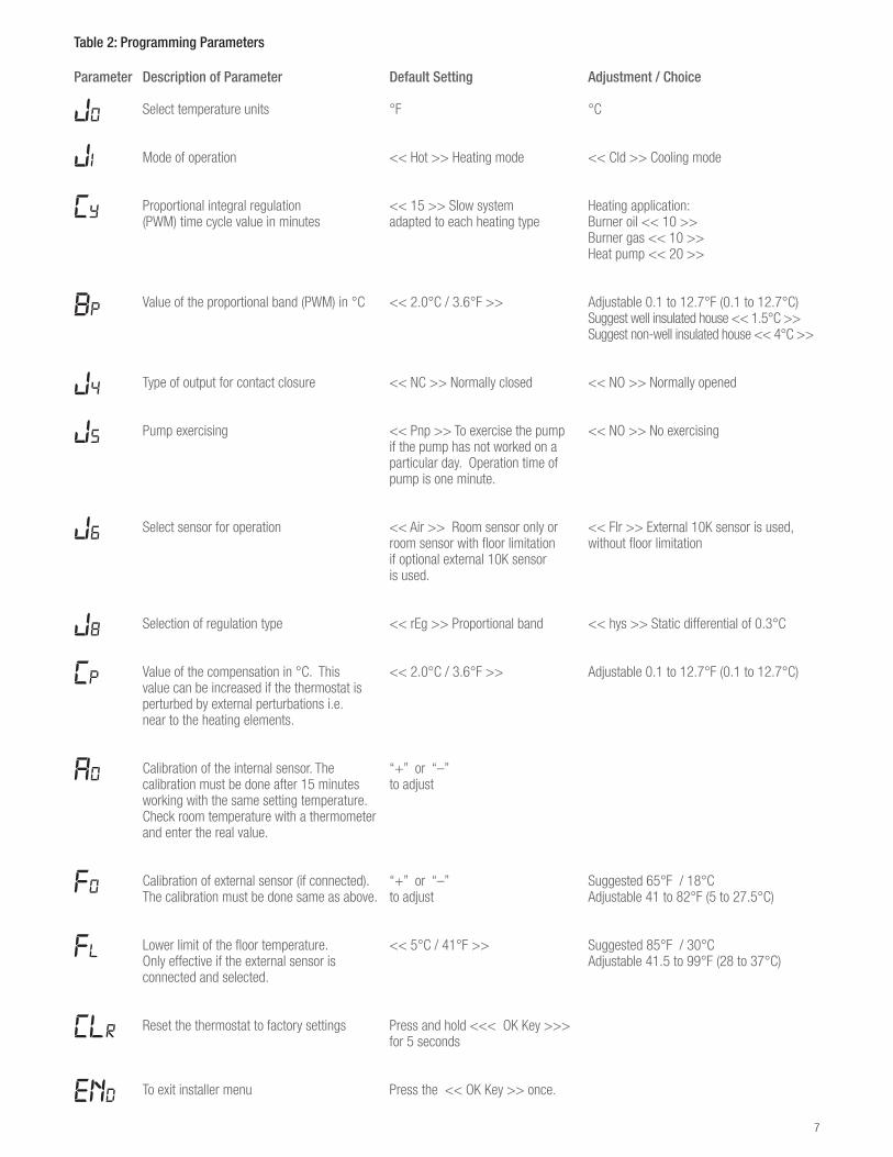
Table 1: Thermostat Technical Specifications
Control Microprocessor controlMaterial White PVC plasticDimensions (H x W x D) 3 1/4 x 3 1/4 x 1 in (80 x 80 x 27 mm)Measured temperature precision 0.2°F (0.1°C)Packaged weight 0.26 lb (97 g)Floor limiting temperature range 50 to 104°F (10 to 40°C)Temperature regulation Proportional integral regulation (adjustable – see installation menu) Cycle: 15 min. or static differential 1.8°F (1°C)Ambient conditions (indoor use only) 32 to 122°F (0 to 50°C), < 90%Electrical protection class Class II – IP30Power supply 24 V ±10% 60 Hz 15 W maxOutput TRIAC output 24 VC, 15W max (typical – 4 actuators)Optional floor sensor NTC thermistor, 10 kΩ; 10 ft (3 m) cable (Art. No. 236497-001)Wire type Minimum of three conductor thermostat wires (18-24 AWG); four or eight conductor thermostat wires are recommended
Thermostat Display Features
OK/
20.5j1°F°C
20.5j1°F°C
1. Operating mode menu2. Heating indication3. Cooling indication4. If symbol is displayed, the measured temperature is shown
(position 5)5. Measured temperature or set temperature6. °C or °F indication7. Title for installation parameters (J0,CLr…)
Fig. 1: Thermostat display features
1
2
3
4
7
6
5
4
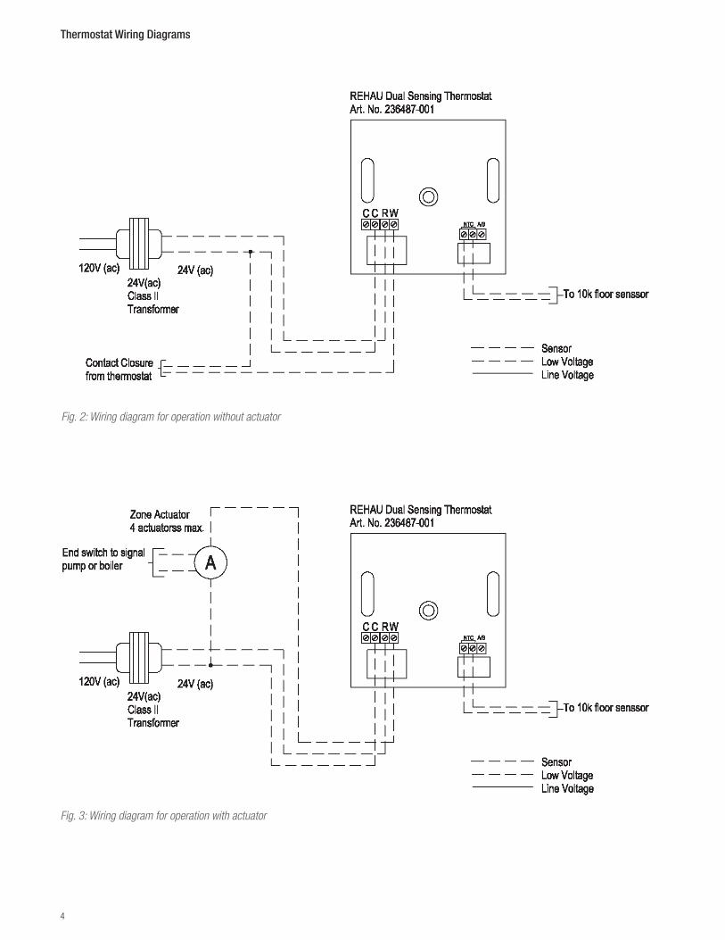
Thermostat Wiring Diagrams
Fig. 2: Wiring diagram for operation without actuator
Fig. 3: Wiring diagram for operation with actuator

5
MOUNTING THE THERMOSTAT
Note: Thermostat must be mounted in the correct location to work properly.
1. Thermostat should be located 1.5 m (5 ft) above the finished floor. The thermostat must be installed on an interior wall. Avoid loca-tions in drafts (e.g., staircases, air outlets), behind doors, in direct sunlight or near other heat sources.
2. Make sure that wire is installed from control location to the desired thermostat location.
3. Use the mounting template (see Fig. 5) to help position the thermo-stat and drill the mounting holes.
4. Pull wires through access holes for thermostat wiring and floor sensor wiring (if applicable). Fasten the screws, but do not com-pletely tighten the screws.
WARNING: Turn off all power to the wires before connecting wires to terminals. Failure to turn off power can cause electrocution.
60 in(1.5 m)Min. 8 in
(20 cm)
Fig. 4: Locating the thermostat
5. Adjust thermostat with a level and tighten the screws.
6. Put the cover on the thermostat and secure with Phillips head screw, using a No. 1 Phillips head screw driver.
7. Apply 24V power.
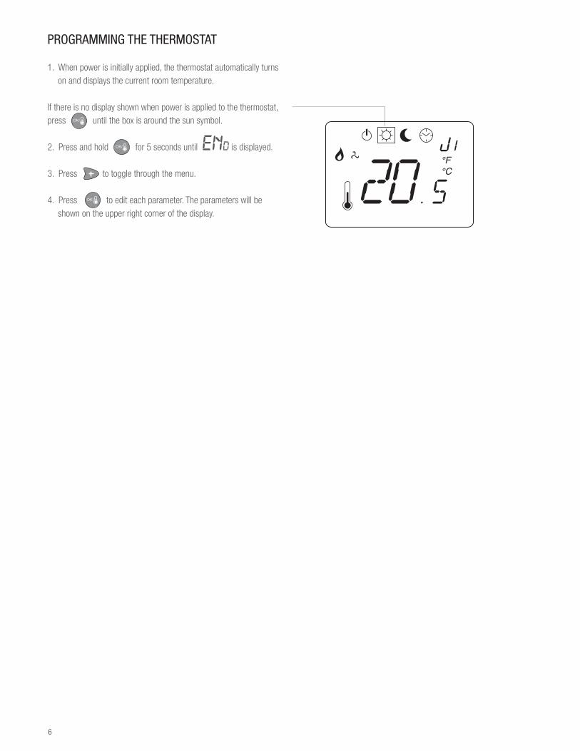
6
20.5j1°F°C
OK/
OK/
OK/
7
8
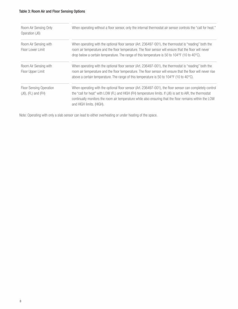
Table 3: Room Air and Floor Sensing Options
Room Air Sensing Only Operation (J6)
When operating without a floor sensor, only the internal thermostat air sensor controls the “call for heat.”
Room Air Sensing with Floor Lower Limit
When operating with the optional floor sensor (Art. 236497-001), the thermostat is “reading” both the room air temperature and the floor temperature. The floor sensor will ensure that the floor will never drop below a certain temperature. The range of this temperature is 50 to 104°F (10 to 40°C).
Room Air Sensing with Floor Upper Limit
When operating with the optional floor sensor (Art. 236497-001), the thermostat is “reading” both the room air temperature and the floor temperature. The floor sensor will ensure that the floor will never rise above a certain temperature. The range of this temperature is 50 to 104°F (10 to 40°C).
Floor Sensing Operation (J6), (FL) and (FH)
When operating with the optional floor sensor (Art. 236497-001), the floor sensor can completely control the “call for heat” with LOW (FL) and HIGH (FH) temperature limits. If (J6) is set to AIR, the thermostat continually monitors the room air temperature while also ensuring that the floor remains within the LOW and HIGH limits. (HIGH).
Note: Operating with only a slab sensor can lead to either overheating or under heating of the space.
9
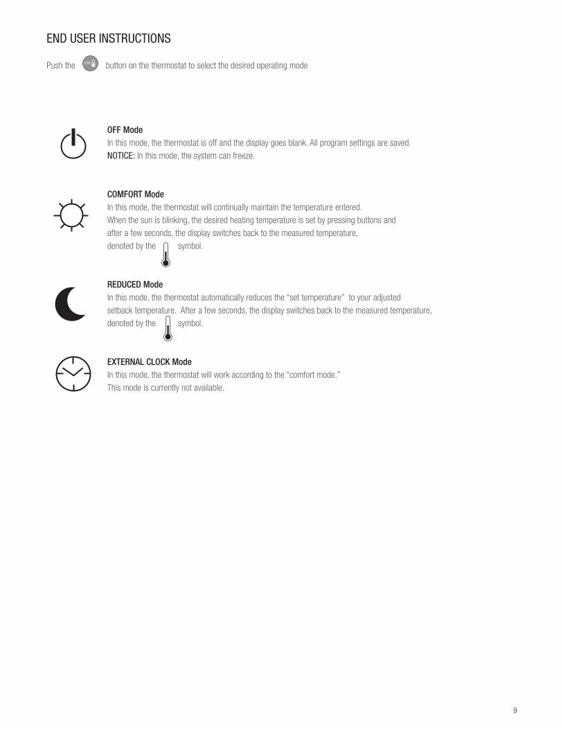
END USER INSTRUCTIONS
Push the OK/ button on the thermostat to select the desired operating mode
OFF ModeIn this mode, the thermostat is off and the display goes blank. All program settings are saved. NOTICE: In this mode, the system can freeze.
COMFORT ModeIn this mode, the thermostat will continually maintain the temperature entered. When the sun is blinking, the desired heating temperature is set by pressing buttons andafter a few seconds, the display switches back to the measured temperature, denoted by the symbol.
REDUCED ModeIn this mode, the thermostat automatically reduces the “set temperature” to your adjusted setback temperature. After a few seconds, the display switches back to the measured temperature, denoted by the symbol.
EXTERNAL CLOCK ModeIn this mode, the thermostat will work according to the “comfort mode.” This mode is currently not available.

10
11
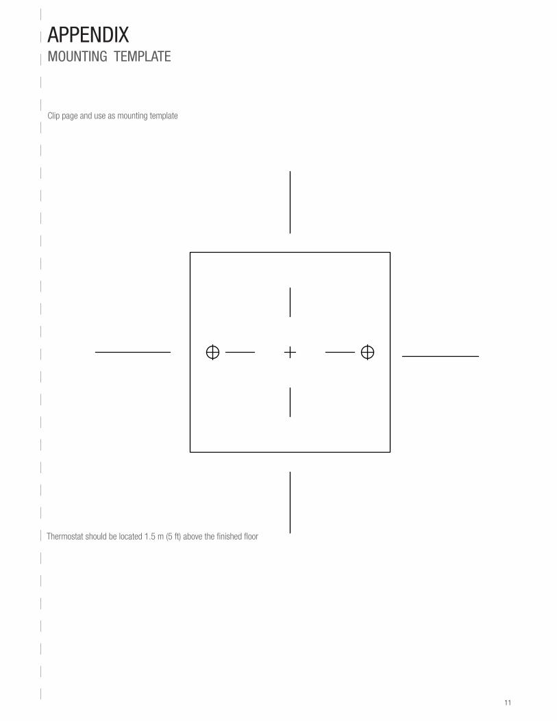
APPENDIX MOUNTING TEMPLATE
Clip page and use as mounting template
Thermostat should be located 1.5 m (5 ft) above the finished floor

www.rehau.com [email protected]
For updates to this publication, visit na.rehau.com/resourcecenter The information contained herein is believed to be reliable, but no representations, guarantees or warranties of any kind are made as to its accuracy, suitability for particular applications or the results to be obtained therefrom. Before using, the user will determine suitability of the information for user’s intended use and shall assume all risk and liability in connection therewith. © 2015 REHAU
855.665 04.2015