Dual Redundancy Guide Version 2 - ABB Ltd® Network Management Guide 1 1TGC 901092 M0201 Edition...
14
ABB Protect IT – MNS Motor Management INSUM Dual Redundancy Guide Version 2.3
Transcript of Dual Redundancy Guide Version 2 - ABB Ltd® Network Management Guide 1 1TGC 901092 M0201 Edition...
ABB
ProtectIT – MNS Motor Management INSUM
Dual Redundancy Guide Version 2.3

INSUM® Network Management Guide
1 1TGC 901092 M0201 Edition December 2002
INSUM® Dual Redundancy Guide
Version 2.3

INSUM®
Dual Redundancy Guide
2 1TGC 901092 M0201 Edition December 2002
NOTICE The information in this document is subject to change without notice and should not be con-strued as a commitment by ABB Schaltanlagentechnik GmbH. ABB Schaltanlagentechnik GmbH assumes no responsibility for any errors that may appear in this document. In no event shall ABB Schaltanlagentechnik GmbH be liable for direct, indirect, special, inci-dental, or consequential damages of any nature or kind arising from the use of this document, nor shall ABB Schaltanlagentechnik GmbH be liable for incidental or consequential damages arising from use of any software or hardware described in this document. This document and parts thereof must not be reproduced or copied without ABB Schaltanla-gentechnik GmbH’s written permission, and the contents thereof must not be imparted to a third party nor be used for any unauthorized purpose. Permission to translate the document shall be obtained from ABB Schaltanlagentechnik GmbH. The translated document shall be sent to ABB Schaltanlagentechnik GmbH together with the confirmation that the content of the document is the same. The software described in this document is furnished under a license and may be used, cop-ied, or disclosed only in accordance with the terms of such license. 2002 ABB Schaltanlagentechnik GmbH, Germany TRADEMARKS MNS and INSUM are registered trademarks of ABB Schaltanlagentechnik GmbH Microsoft, Windows and Windows NT are registered trademarks of Microsoft Corporation. Echelon, LON, LONWORKS, LonTalk, Neuron are trademarks of Echelon Corporation regis-tered in U.S. and other countries. Reference Document: 1TGL999004 R1.2

INSUM®
Dual Redundancy Guide
3 1TGC 901092 M0201 Edition December 2002
1 General ................................................................................................................................4 1.1 Objective ....................................................................................................................4 1.2 Application advice ......................................................................................................4 1.3 Related Documentation .............................................................................................4
2 INSUM Philosophy of Dual Redundancy..........................................................................5 2.1 Background................................................................................................................5 2.2 Dual Redundancy Interpretation ................................................................................5
2.2.1 Dual Gateway Configuration .........................................................................5 2.2.2 Dual Backplane Configuration.......................................................................5
3 Schematics .........................................................................................................................6 3.1 Dual Gateway Configuration ......................................................................................6 3.2 Schematic Dual Backplane Configuration .................................................................7
Annex A: INSUM Terms and Abbreviations ...........................................................................8

INSUM® Dual Redundancy Guide
4 ABB 1TGC 901092 M0201 Edition December 2002
Notes: 1 General 1.1 Objective
The objective of the document is to advise on the interpretation of dual redundancy in INSUM and the most recommended dual redundant configuration.
1.2 Application advice
Refers to all types of Gateways in dual redundant INSUM configuration, INSUM Router hardware rev.3.0
1.3 Related Documentation
1TGC 901007 B0201 INSUM Technical Information 1TGC 901021 M0201 INSUM MCU Users Guide 1TGC 901026 M0201 INSUM MCU Parameter Description 1TGC 901034 M0201 INSUM MMI Operating Instruction 1TGC 901030 M0201 INSUM MMI Quick Guide 1TGC 901042 M0201 INSUM Modbus Gateway Manual 1TGC 901052 M0201 INSUM Profibus Gateway Manual 1TGC 901060 M0201 INSUM Ethernet Gateway Manual 1TGC 901080 M0201 INSUM System Clock Manual 1TGC 901090 M0201 INSUM Control Access Guide 1TGC 901091 M0201 INSUM Failsafe Guide 1TGC 901093 M0201 INSUM Network Management Guide SACE RH 0080 Rev.l PR112/ PD-L LON Works Interface V2.0 1SEP 407948 P0001 Users Manual Intelligent Tier Switch (ITS)

INSUM® Dual Redundancy Guide
5 ABB 1TGC 901092 M0201 Edition December 2002
Notes: 2 INSUM Philosophy of Dual Redundancy 2.1 Background
INSUM provides the communication interface to the plant process control system (PCS/DCS) or any other external supervisory system by means of Gateways. Existing Gateways types support MODBUS, PROFIBUS-DP and Ethernet communication protocol.
If a higher availability (dual redundancy) is required, two alternatives are provided by INSUM to support such requirements.
2.2 Dual Redundancy Interpretation
The data provided from INSUM to the process control system shall be available dual redundant (two com-munication links to the PCS/DCS). INSUM supports two parallel communication lines to the PCS and provides the same data continuously at all times on both lines.
The following alternatives are available:
• Dual Gateway Configuration • Dual Backplane Configuration
One Gateway/backplane shall be selected active for control from the PCS, the second Gateway/backplane constantly exchanges a ‘handshake’ initiated by the PCS controller to ensure an active communications link. In the event of loss of communication on the active link or loss of component, the PCS has to initiate the switch-over and maintain control and monitoring through the second Gateway/backplane.
Note: In both of the alternatives, the dual bus redundancy ends at the Gateway level. The redundancy is not further extended down to the MCU level. On no account the INSUM dual redundancy should be expected below the Gateway level. Although the ring network structure is possible for MCU subnets but should not be misinterpreted as a support to achieve the MCU redundancy.
2.2.1 Dual Gateway Configuration
INSUM supports the dual bus redundancy of the communication interface by duplicating the Gateways. Both Gateways are residing on the same backplane. The Gateways are constantly updated by each field device. The handling of redundancy must then be performed by the external system (PCS/DCS).
INSUM allows the communication at all times on both lines but whereas switching over, failure detection and other functions needed for adequate handling of dual redundancy are not the scope of INSUM.
See fig.1 on page 5
2.2.2 Dual Backplane Configuration
The INSUM availability can be increased further by using two backplanes. In this configuration, the Gate-ways are mounted on separate backplanes. The handling of dual redundancy must still be performed by the external system (PCS/DCS). To ensure maximised system security and availablility each backplane shall be individually supplied from a secure voltage source. Further, the serial links from the Gateways to the PCS should be routed via alternate paths in the plant. The system architecture allows each Gateway to be constantly updated by each field device.
INSUM allows the communication at all times on both lines but whereas switching over, failure detection and other functions needed for adequate handling of dual redundancy are not the scope of INSUM.
See fig.2 on page 6

INSUM® Dual Redundancy Guide
6 ABB 1TGC 901092 M0201 Edition December 2002
Notes: 3 Schematics 3.1 Dual Gateway Configuration
Picture 1. Dual Gateway Configuration
Abb
revi
atio
nsLO
N
Lo
cal O
pera
ting
Net
wor
kM
MI
M
an M
achi
ne In
terfa
ceM
CU
M
otor
Con
trol U
nit
Plan
t Con
trol S
yste
m Up
to fo
ur L
ON
link
s w
ith u
p to
32
devi
ces
per l
ink,
tota
l 128
dev
ices
(dep
ends
on
gate
way
type
use
d).
Red
unda
ntco
mm
unic
atio
n lin
es
No
redu
ndan
cy b
elow
this
par
t,ex
cept
gat
eway
s
INS
UM
MM
I®
INSU
M O
S®
LON
Bus
@ 7
8kBa
ud
Ethe
rnet
TC
P/IP

INSUM® Dual Redundancy Guide
7 ABB 1TGC 901092 M0201 Edition December 2002
Notes: 3.2 Schematic Dual Backplane Configuration
Picture 2. Dual Backplane Configuration
Ethe
rnet
TC
P/IP
Abbr
evia
tions
LON
L
ocal
Ope
ratin
g N
etw
ork
MM
I
Man
Mac
hine
Inte
rface
MC
U
Mot
or C
ontro
l Uni
t
Plan
t Con
trol S
yste
m MC
U
Red
unda
ntco
mm
unic
atio
n lin
es
No
redu
ndan
cy b
elow
this
par
t INSU
M O
S®
INS
UM
MM
I®
Four
LO
N li
nks
with
up
to 3
2 de
vice
s pe
r lin
k, to
tal 1
28 d
evic
es (d
epen
ds o
n ga
tew
ay ty
pe u
sed)
.
INSU
M M
MI
®
INSUM® Dual Redundancy Guide
8 ABB 1TGC 901092 M0201 Edition December 2002
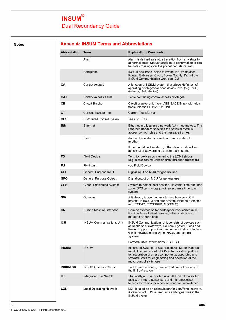
Notes: Annex A: INSUM Terms and Abbreviations Abbreviation Term Explanation / Comments
Alarm Alarm is defined as status transition from any state to abnormal state. Status transition to abnormal state can be data crossing over the predefined alarm limit.
Backplane INSUM backbone, holds following INSUM devices: Router, Gateways, Clock, Power Supply. Part of the INSUM Communication Unit, see ICU
CA Control Access A function of INSUM system that allows definition of operating privileges for each device level (e.g. PCS, Gateway, field device)
CAT Control Access Table Table containing control access privileges
CB Circuit Breaker Circuit breaker unit (here: ABB SACE Emax with elec-tronic release PR112-PD/LON)
CT Current Transformer Current Transformer
DCS Distributed Control System see also PCS
Eth Ethernet Ethernet is a local area network (LAN) technology. The Ethernet standard specifies the physical medium, access control rules and the message frames.
Event An event is a status transition from one state to another.
It can be defined as alarm, if the state is defined as abnormal or as warning as a pre-alarm state.
FD Field Device Term for devices connected to the LON fieldbus (e.g. motor control units or circuit breaker protection)
FU Field Unit see Field Device
GPI General Purpose Input Digital input on MCU for general use
GPO General Purpose Output Digital output on MCU for general use
GPS Global Positioning System System to detect local position, universal time and time zone, GPS technology provides accurate time to a system
GW Gateway A Gateway is used as an interface between LON protocol in INSUM and other communication protocols (e.g. TCP/IP, PROFIBUS, MODBUS)
HMI Human Machine Interface Generic expression for switchgear level communica-tion interfaces to field devices, either switchboard mounted or hand held
ICU INSUM Communications Unit INSUM Communications Unit consists of devices such as backplane, Gateways, Routers, System Clock and Power Supply. It provides the communication interface within INSUM and between INSUM and control systems.
Formerly used expressions: SGC, SU
INSUM INSUM Integrated System for User optimized Motor Manage-ment. The concept of INSUM is to provide a platform for integration of smart components, apparatus and software tools for engineering and operation of the motor control switchgea
INSUM OS INSUM Operator Station Tool to parameterise, monitor and control devices in the INSUM system
ITS Integrated Tier Switch The Intelligent Tier Switch is an ABB SlimLine switch fuse with integrated sensors and microprocessor based electronics for measurement and surveillance
LON Local Operating Network LON is used as an abbreviation for LonWorks network. A variation of LON is used as a switchgear bus in the INSUM system
Notes:
INSUM® Dual Redundancy Guide
9 ABB 1TGC 901092 M0201 Edition December 2002
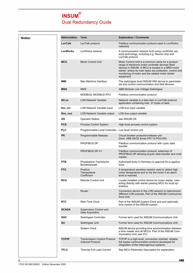
Notes: Abbreviation Term Explanation / Comments
LonTalk LonTalk protocol Fieldbus communication protocol used in LonWorks networks
LonWorks LonWorks network A communication network built using LonWorks net-work technology, including e.g. Neuron chip and LonTalk protocol
MCU Motor Control Unit Motor Control Unit is a common name for a product range of electronic motor controller devices (field device) in INSUM. A MCU is located in a MNS motor starter, where its main tasks are protection, control and monitoring of motor and the related motor starter equipment.
MMI Man Machine Interface The switchgear level INSUM HMI device to parameter-ize and control communication and field devices.
MNS MNS ABB Modular Low Voltage Switchgear
MODBUS, MODBUS RTU Fieldbus communication protocol
NV,nv LON Network Variable Network variable is a data item in LonTalk protocol application containing max. 31 bytes of data.
Nvi, nvi LON Network Variable input LON bus input variable
Nvo, nvo LON Network Variable output LON bus output variable
OS Operator Station see INSUM OS
PCS Process Control System High level process control system
PLC Programmable Local Controller Low level control unit
PR Programmable Release Circuit breaker protection/release unit (here: ABB SACE Emax PR112-PD/LON)
PROFIBUS DP Fieldbus communication protocol with cyclic data transfer
PROFIBUS DP-V1 Fieldbus communication protocol, extension of PROFIBUS DP allowing acyclic data transfer and multi master.
PTB Physikalisch-Technische Bundesanstalt
Authorized body in Germany to approve Ex-e applica-tions.
PTC Positive Temperature Coefficient
A temperature sensitive resistor used to detect high motor temperature and to trip the motor if an alarm level is reached.
RCU Remote Control Unit Locally installed control device for motor starter, inter-acting directly with starter passing MCU for local op-erations.
Router Connection device in the LON network to interconnect different LON subnets. Part of the INSUM Communica-tions Unit.
RTC Real Time Clock Part of the INSUM System Clock and and optionally time master of the INSUM system
SCADA Supervisory Control and Data Acquisition
SGC Switchgear Controller Former term used for INSUM Communications Unit
SU Switchgear Unit Former term used for INSUM Communications Unit
System Clock INSUM device providing time synchronisation between a time master and all MCUs. Part of the INSUM Com-munication Unit, see ICU
TCP/IP Transmission Control Protocol /Internet Protocol
TCP/IP is a high-level, connection oriented, reliable, full duplex communication protocol developed for integration of the heterogenous systems.
TFLC Thermal Full Load Current See MCU Parameter Description for explanation

INSUM® Dual Redundancy Guide
10 ABB 1TGC 901092 M0201 Edition December 2002
Notes: Abbreviation Term Explanation / Comments
TOL Thermal Overload See MCU Parameter Description for explanation
Trip A consequence of an alarm activated or an external trip command from another device to stop the motor or trip the circuit breaker.
UTC Coordinated Universal Time Coordinated Universal Time is the international time standard, formerly referred to as Greenwich Meridian Time (GMT). Zero (0) hours UTC is midnight in Greenwich England, which lies on the zero longitudinal meridian. Universal time is based on a 24 hours clock.
VU Voltage Unit Voltage measurement and power supply unit for MCU 2
Wink The Wink function enables identifcation of a device on the LON network. When a device receives a Wink-message via the fieldbus, it responds with a visual indication (flashing LED)


Editor: DEAST/BTPublication No: 1TGC901092M0201
ABB Schaltanlagentechnik GmbHWallstadter Str. 59D - 68526 Ladenburg / Germany
Related Products, News, Local Contacts:www.abb.com/mns