Dual purpose no voltage winding design for the … 2014 International Power Electronics Conference...
8
The 2014 International Power Electronics Conference Dual purpose no voltage winding design for the bearingless ac homopolar and consequent pole motors Eric Severson*, Robert Nilssen t , Tore Undeland t , and Ned Mohan* *Department of Electrical and Computer Engineering University of Minnesota, Minneapolis, Minnesota 55455 Email: [email protected] t Department of Electric Power Engineering Norwegian University of Science and Technology, Trondheim, Norway Email: [email protected] Abstract-Winding layouts for the bearingless ac ho- mopolar and consequent pole motors that allow the same coils to be used for both radial force and torque production are investigated. This concept enables a "pure" bearingless motor where the same iron and copper are used for both magnetic bearing operation and torque production. For three phase windings, it is shown that these schemes limit 6-pole machines to integral slot windings, but that 8-pole machines support various fractional slot windings. Conclusions are similarly drawn for two phase windings. A winding design procedure is proposed and 3D finite element analysis (FEA) results are presented for an example design. Keywords-Bearingless machines, bridge configured wind- ing, se-bearing moto single motor winding I. INTRODUCTION By definition, bearingless electric machines are ma- chines which are able to use the same iron to function as both a motor and a magnetic bearing. In conventional bearingless machines, this requires two sets of stator windings: an armature winding for torque production and a suspension winding for magnetic bearing operation. Typically, the suspension winding and the torque winding will share the same stator slots. The slot space allocated to the suspension winding must be large enough to achieve an acceptable current density for a worst-case (highest-possible) suspension current. For machines that are vertically oriented and experience no net radial forces, such as those used in flywheel energy storage, this worse- case suspension current may only occur on rare occasions. An example of such an occasion is during start-up, when the rotor is highly eccentric. For these machines, the normal suspension current is small compared to the worst- case scenario and therefore during typical operation the current density in the suspension winding is very low. This wastes valuable slot space that could otherwise be used for the torque winding, degrading the machine's motor performance. Recently, several papers have proposed winding meth- ods which use the same coils to produce both radial forces and torque [1], [2], [3], [4], [5]. Such methods 978-1-4799-2705-0/14/$31.00 ©2014 IEEE 1412 allow for more optimal machine performance as the entire slot space can be used to carry torque-producing current when no magnetic bearing forces are required. In [2], [3], [4], [5] these methods have been explored on bearing1ess versions of classical machines. In [1], a new type of machine is proposed which inherently has this feature. No investigation has been carried out on applying such techniques to the bearing1ess ac homopolar or consequent pole motors. This paper investigates applying the two techniques above that result in no motional-EMF for the suspension winding [2], [3], [5], so-called "dual purpose no voltage" windings, to the bearingless ac homopolar motor. The same results are true for the bearingless con- sequent pole motor, a study of which is omitted because its required drive system is a simpler version of the drive system required for the bearingless ac homopolar motor. In this paper, the application of "dual purpose no volt- age" windings to the bearingless ac homopolar motor is explained, design rules for these windings are developed, a design approach is proposed, and FEA of an example design is presented. II. BEARINGLESS AC HOMO POLAR MOTOR The ac homopo1ar motor, also known as the homopo- 1ar inductor alternator and the synchronous homopo1ar motor, has a robust rotor structure, uses stator-side current excitation, and has its poles in parallel with the magnetiz- ing flux, which means that no additional ampere-turns of field winding current are required when increasing the number of poles. These features have attracted recent interest in implementing the ac homopolar motor as a high-speed machine, a super-conducting machine, and a high-equency generator [6], [7], [8]. As a bearingless machine, work has focused on considering this machine in applications where magnetic bearings are typically required, such as in high-speed machinery [9], [10]. The authors of this work are interested in using the machine in a flywheel energy storage system. This is because, in addition to eliminating the need for radial magnetic bearings, the bearing1ess ac homopolar motor's current- based excitation can easily be adjusted to allow for lower iron losses.
Transcript of Dual purpose no voltage winding design for the … 2014 International Power Electronics Conference...

The 2014 International Power Electronics Conference
Dual purpose no voltage winding design for the
bearingless ac homopolar and consequent pole
motors
Eric Severson*, Robert Nilssent, Tore Undelandt, and Ned Mohan*
*Department of Electrical and Computer Engineering
University of Minnesota, Minneapolis, Minnesota 55455
Email: [email protected] tDepartment of Electric Power Engineering
Norwegian University of Science and Technology, Trondheim, Norway
Email: [email protected]
Abstract-Winding layouts for the bearingless ac ho
mopolar and consequent pole motors that allow the same
coils to be used for both radial force and torque production
are investigated. This concept enables a "pure" bearingless
motor where the same iron and copper are used for
both magnetic bearing operation and torque production.
For three phase windings, it is shown that these schemes
limit 6-pole machines to integral slot windings, but that
8-pole machines support various fractional slot windings.
Conclusions are similarly drawn for two phase windings. A
winding design procedure is proposed and 3D finite element
analysis (FEA) results are presented for an example design.
Keywords-Bearingless machines, bridge configured wind
ing, self-bearing motor, single motor winding
I. INTRODUCTION
By definition, bearingless electric machines are machines which are able to use the same iron to function as both a motor and a magnetic bearing. In conventional bearingless machines, this requires two sets of stator windings: an armature winding for torque production and a suspension winding for magnetic bearing operation. Typically, the suspension winding and the torque winding will share the same stator slots. The slot space allocated to the suspension winding must be large enough to achieve an acceptable current density for a worst-case (highest-possible) suspension current. For machines that are vertically oriented and experience no net radial forces, such as those used in flywheel energy storage, this worsecase suspension current may only occur on rare occasions. An example of such an occasion is during start-up, when the rotor is highly eccentric. For these machines, the normal suspension current is small compared to the worstcase scenario and therefore during typical operation the current density in the suspension winding is very low. This wastes valuable slot space that could otherwise be used for the torque winding, degrading the machine's motor performance.
Recently, several papers have proposed winding methods which use the same coils to produce both radial forces and torque [1], [2], [3], [4], [5]. Such methods
978-1-4799-2705-0/14/$31.00 ©2014 IEEE 1412
allow for more optimal machine performance as the entire slot space can be used to carry torque-producing current when no magnetic bearing forces are required. In [2], [3], [4], [5] these methods have been explored on bearing1ess versions of classical machines. In [1], a new type of machine is proposed which inherently has this feature. No investigation has been carried out on applying such techniques to the bearing1ess ac homopolar or consequent pole motors. This paper investigates applying the two techniques above that result in no motional-EMF for the suspension winding [2], [3], [5], so-called "dual purpose no voltage" windings, to the bearingless ac homopolar motor. The same results are true for the bearingless consequent pole motor, a study of which is omitted because its required drive system is a simpler version of the drive system required for the bearingless ac homopolar motor.
In this paper, the application of "dual purpose no voltage" windings to the bearingless ac homopolar motor is explained, design rules for these windings are developed, a design approach is proposed, and FEA of an example design is presented.
II. BEARINGLESS AC HOMO POLAR MOTOR
The ac homopo1ar motor, also known as the homopo-1ar inductor alternator and the synchronous homopo1ar motor, has a robust rotor structure, uses stator-side current excitation, and has its poles in parallel with the magnetizing flux, which means that no additional ampere-turns of field winding current are required when increasing the number of poles. These features have attracted recent interest in implementing the ac homopolar motor as a high-speed machine, a super-conducting machine, and a high-frequency generator [6], [7], [8]. As a bearingless machine, work has focused on considering this machine in applications where magnetic bearings are typically required, such as in high-speed machinery [9], [10]. The authors of this work are interested in using the machine in a flywheel energy storage system. This is because, in addition to eliminating the need for radial magnetic bearings, the bearing1ess ac homopolar motor's currentbased excitation can easily be adjusted to allow for lower iron losses.

The 2014 International Power Electronics Conference
x
(a) Bearingless ac homopolar machine (b) Magnetization (c) x-axis force production
Fig. 1. The bearingless ac homopolar machine: (a) 3-D cross-section, (b) axial view of the magnetization created by the field winding, (c) depiction of flux density created by an x-phase suspension winding for radial force production.
For bearingless versions of classical synchronous motors to create radial force, a p ± 1 pole-pair flux density must be created in the airgap to disrupt the otherwise symmetric p pole-pair flux density. To produce a constant direction force, this p ± 1 pole-pair flux must rotate with the p pole-pair flux. This requires an ac suspension current, high-bandwidth angular position sensors, and imposes stringent control requirements [9]. On the other hand, the bearingless ac homopolar and consequent pole motors with at least 8-poles are able to produce a constant direction force with dc suspension current, regardless of the rotor's angular position. This substantially reduces the cost and complexity of the bearingless motor drive.
A diagram of the bearingless ac homopolar motor explaining torque and radial force production is depicted in Fig. l. The airgap flux density is created by MMFs from three different windings: a dc field winding which is fixed to the stator and wraps around the rotor circumferentiallyFf, a 2p-pole synchronous torque winding located in the stator slots and spanning the full axial length of the machine-FT, and a 2-pole suspension winding which shares slot space with the stator winding but only spans a single rotor/stator section-Fs,,p. The radial airgap flux density can be calculated by imposing each of these MMF's upon an effective airgap length:
gu(a,e) = hl+h2!Cp[a-e])) (1)
gz (a, e) = h1+h2!(pla-el+11")) (2)
() Fto tal ,,p
(3) B,p a, e = ILO ( e) -
g,p a,
Here, gu is the effective upper airgap length at the stator location a when the p-pole pair rotor is at the rotational angle e; f is a function expressed as a summation of the harmonic terms in the airgap; the subscript '1jJ is used to indicate whether a quantity applies to the upper airgap ('I/J = u) or the lower airgap (ot/) = l).
In the simplest case of idealized sinusoidal windings and a sinusoidal effective airgap length:
f (cP) = coscP FT = FT cos (p [e - a] + cPT)
Fs,,p = Fs,,p cos (-a + cPs,,p)
1413
The airgap flux density resulting from each MMF can be expressed as a sum of harmonic terms as:
Bu (a, e) = BF (a, e) + BT (a, e) + Bs (a, e) (4)
BF (a, e) = fLohlFf + ILoh2 Ff cos (p [a - e])
BT (a, e) = fLo \2 FT cos cPT
+ fLohlFT cos (p [e - a] + cPT)
+ fLo h22 FT cos (2p [a - e] - cPT)
Bs (a, e) = fLohli:" cos (a - cPs)
+ M(�h2 Fs cos ([p -1] a - pe + cPs)
+ M02h2 Fs cos ( [p + 1] a - pe + cPs)
The radial forces created by (4) can be calculated using the Maxwell Stress Tensor (5). It can be shown that the only flux density terms which contribute to radial force generation differ in harmonic index by one. Provided that p 2 4, these terms' dependence on the rotor's angular position e will cancel each other out, proving that the bearingless ac homopolar motor is able to create forces independent of its rotor's angular position. Note that the only torque winding term which contributes to the radial forces is proportional to the current angle:
cos cPT. If no direct-axis current is present, cPT = 900 and the magnetic suspension operation is independent of the motor operation. These results break down for p < 4. However, it was shown in [10] that careful winding design can still allow for stable levitation when p = 3. Practical suspension and torque windings contain harmonics other than the fundamental which introduces some radial force dependence on the rotor's angular position. More information regarding the theory of operation can be found in [11], [12].
1211" 1 2 Fx,,p(e) = -B,p(a,e) lrcosada o 2/Lo 1211" 1 2 Fy,,p(e) = -B,p(a,e) lrsinada o 2/Lo (5)
III. DUAL PURPOSE No VOLTAGE BEARINGLESS
WINDINGS
Combining the suspension and torque windings into a single set of coils means having a winding with multiple
The 2014 International Power Electronics Conference
(a) Coils excited as torque winding (b) Coils excited as suspension winding
(c) Phase u excited as torque winding (d) Phase u excited as suspension winding
Fig. 2. Depiction of a 36 slot stator winding with coils that when excited from one set of terminals produce an 8-pole MMF and when excited from a separate set of terminals produce a 2-pole MMF.
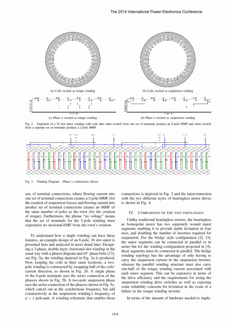
Fig. 3. Winding Diagram - Phase u connections shown.
sets of terminal connections, where flowing current into one set of terminal connections creates a 2-pole MMF (for the creation of suspension forces) and flowing current into another set of terminal connections creates an MMF of the same number of poles as the rotor (for the creation of torque). Furthermore, the phrase "no voltage" means that the set of terminals for the 2-pole winding must experience no motional-EMF from the rotor's rotation.
To understand how a single winding can have these features, an example design of an 8-pole, 36 slot stator is presented here and analyzed in more detail later. Designing a 3-phase, double-layer, fractional-slot winding in the usual way with a phasor diagram and 60° phase belts [13], see Fig. Sa, the winding depicted in Fig. 2a is produced. Now, keeping the coils in their same locations, a twopole winding is constructed by swapping half of the coils' current direction, as shown in Fig. 2b. A single phase of the 8-pole terminals sees the series connection of the phasors shown in Fig. Sb. A two-pole suspension phase sees the series connection of the phasors shown in Fig. Sc, which cancel out at the synchronous frequency but add constructively at the suspension winding's frequency of p = 1 pole-pair. A winding schematic that enables these
1414
connections is depicted in Fig. 3 and the interconnection with the two different styles of bearingless motor drives is shown in Fig. 4.
IV. COMPARISON OF T HE TWO TOPOLOGIES
Unlike traditional bearingless motors, the bearingless ac homopolar motor has two separately wound stator segments enabling it to provide stable levitation in four axes, and doubling the number of inverters required for suspension. For the bridge style configuration [2], [3], the stator segments can be connected in parallel or in series but for the winding configuration proposed in [4], these segments must be connected in parallel. The bridge winding topology has the advantage of only having to carry the suspension current in the suspension inverter, whereas the parallel winding structure must also carry one-half of the torque winding current associated with each stator segment. This can be expensive in terms of the drive efficiency and the requirements for sizing the suspension winding drive switches as well as exposing some reliability concerns for levitation in the event of a failure in the torque winding inverter.
In terms of the amount of hardware needed to imple-

The 2014 International Power Electronics Conference
Top Stator Winding
1"
(a) Bridge Winding (b) Parallel Winding
Fig. 4. Winding connections for the styles of dual-purpose windings considered. The coil names correspond to the labels in Fig. 3 where the dotted terminals match the subscript "+'
ment each inverter, the bridge winding is at a significant disadvantage, as each of the suspension current sources in Fig. 4a must be implemented as an isolated single phase inverter. Furthermore, it will be shown in the following section that the bridge winding is more restrictive on the types of windings that can be used.
V. WINDING DESIGN REQUIREMENTS
Only certain combinations of the number stator coils zc, stator slots Q, phases m, and rotor pole-pairs p can be used to realize a dual purpose no voltage winding. Restrictions on these combinations are now investigated.
A. Number of coils per phase winding
The bridge winding configuration requires that each phase winding have a multiple of four coils per phase: zclm = 4k; the parallel winding configuration requires that each phase winding have a multiple of two coils per phase zclm = 2k.
B. Symmetry conditions
A symmetry condition for fractional slot windings requires that the number of phases, m, be co-prime with the denominator of q (6), the number of slots per pole per phase [13]. Imposing this requirement along with the required number of coils per phase, restricts the types of winding that can be used.
Q z q = -- = 2mp n
(6)
In a single layer winding, the number of coils is Zc = Q /2 and in a double layer winding Zc = Q. Recalling that k is
1415
TABLE I.
Number of layers
Single
Double
SLOTS PER POLE PER PHASE
Parallel Connection
q = ¥f k
q = p
Bridge Connection
q = o/f
q= �
TABLE II. POSSIBLE DENOMINATORS OF q WHEN P = 4
Number of layers Parallel Connection Bridge Connection
Single n = 1 or 2 n = 1
Double n = 1, 2, or 4 n = 1 or 2
an integer, q is restricted to the values shown in Table I. The bearingless ac homopolar motor is most commonly used as a p = 4 and, under special circumstances, as a p = 3 pole-pair machine for reasons previously described.
For a six pole machine (p = 3), it can be seen from Table I that the denominator of q will be always be either 3 (fractional-slot) or 1 (integral slot). This means that a fractional-slot m = 3-phase winding cannot be used as it would violate the symmetry condition; however, 6-pole, two-phase fractional slot and three-phase integral slot windings are permissible.
The situation is a bit more complex for an 8-pole machine (p = 4) and is summarized in Table II. A singlelayer bridge configuration will always yield n = 1, which is an integral-slot design, and in all fractional slot designs (n # 1), n is even. This means that a reduced winding (such as an m = 2 phase winding) must be an integral slot design. However, in this case, three-phase fractional slot windings are permissible.

The 2014 International Power Electronics Conference
TABLE III. POSSIBLE DUAL PURPOSE No VOLTAGE WINDINGS
p=4 p=3
m=3 m=2 m=3 m=2
Q/m q Q t DL PIB SL PIB Q t DL PIB SL PIB q Q t DL PIB SL PIB Q t DL PIB SL PIB
2 1 6 2 P 4 4 4:
4 1 12 4 P, B P 8 4 2
6 3 18 2 P 12 4 4:
8 1 2 4 4 P, B P, B 16 4 P, B
10 G 30 2 P 20 4 4:
12 3 36 4 P, B P 2 4 4 2
14 7 42 2 P 28 4 4:
16 2 48 4 P, B P, B 32 4 P, B
C Restrictions necessary for no suspension voltage
The two-pole suspension phase terminals utilize the same coils as the 2p-pole torque phase terminals, but have half of the coils connected in the opposite direction in a way that cancels out the motional-EMF of the 2ppole rotor, The conditions necessary to facilitate this can be visualized in the winding star of phasors for the synchronous frequency as requiring either:
a) that each phase contain pairs of phasors that are 180 electrical degrees apart from one another, or
b) that each phase contain pairs of phasors that are at the same location,
If this condition is satisfied by criteria a), then careful consideration of end-turn connections must be made to insure that each phasor in a 180° pair is part of a separate coiL While this is always true in a double-layer lap winding with 60° phase belts, it may not be true for other winding layout approaches or single-layer windings.
VI. WINDING DESIGN
The design of dual purpose no voltage windings is now considered in detail. It is assumed that the machine should first and foremost be a good motor and that the magnetic bearing performance is a secondary concern. With this in mind, the design strategy is to first construct the desired torque winding (which supports a dual purpose winding) and then choose which half of the coils the direction of current flow should be reversed for the suspension terminals. Emphasis is placed on p = 4 polepole, m = 3 phase machines as this is the most common configuration for the bearingless ac homopolar motor.
A. Torque winding
The first step in the winding design is to layout a torque winding which supports a dual purpose winding scheme. Table III provides a list of two and three phase windings for Q 1m .-::: 16 when p = 3 and 4 that meet the previously described winding requirements. The table indicates whether a double layer parallel or bridge connection is possible in the "DL P/B" column and whether a single layer parallel of bridge connection is possible in the "SL P/B" column.
P, B
P, B
1416
1 6 3 4 1 P "3 2 12 3 8 1 P, B P "3
1 18 3 P 12 3 P
4 2 4 3 16 1 P, B P, B "3 5 30 3 20 1 P "3
2 36 3 P, B P 2 4 3 P, B P
7 42 3 28 1 P "3 8 48 3 32 1 P, B P, B "3
The chosen winding should be layed-out in a manner that locates phasors which are displaced by multiples of 180° in the same phase. For double-layer windings, this is done when the phasor star method is used with 60° phase belts.
B. Selection of suspension winding coils
The second step of the winding design is to determine which coils should be flipped in direction for series connection to the suspension winding terminals. The primary goal is to cancel out the motional-EMF. This requires that each phasor be matched to one which is 180° out of phase at the synchronous frequency. By having selected a winding from Table III and layed it out in a manner that guarantees that phasors displaced by multiples of 180° are in the same phase and aligned in the same direction (i.e. +u phasor at 0° and a -u phasor at 180°), it is guaranteed to be possible to cancel the motional-EMF. There will typically be several combinations of phasors which meet this requirement. The best combination is determined by optimizing the suspension winding factors to either maximize the amount of force produced per ampere of suspension current (maximizing the fundamental winding factor) or reducing the amount of ripple in the suspension force as a function of rotor position (minimizing the harmonics in the suspension winding).
C Design when p = 4, m = 3
When redrawing the phasor star at the frequency of the suspension winding (p = 1), the angular distance between each phasor will scale to a factor of lip of the angular distance in the synchronous frame. For a p = 4 winding, t is either 2 or 4. When t = 2, two aligned phasors will be 720 electrical degrees apart, meaning that when they are redrawn in the suspension winding frequency, they will be 180° degrees apart. Flipping one of these phasors to cancel at the p = 4 frequency will cause them to constructively add at the suspension winding's p = 1 frequency. In the case of t = 4, there will be four layers to the phasor star, meaning that each phasor will be 360° apart. When redrawn at the suspension winding frequency, this one phasor will split into four phasors 90° apart that when half of which are flipped will create two orthogonal phasors 90° apart. For either value of t, this means:

The 2014 International Power Electronics Conference
20 11
2 29
21 12
-u _ 30 3
-w
35 26 17
S +U
25 34 7 ](j
33 15 6
24 -V
(a) Torque winding design
-30 �,
8 7 " \ -21
35 16 '" - - :: ::: � *:"'=----+ 34 17«--
/ .. -3
25 2(j
(c) Sus. phase u, h = 1
-21
f:'7 � .1
�
-12
7 Hi
(b) Torque phase u
/ .. 17
I I
-3 :- 35
�<-::----+ 34
-�-30
26
(d) Sus. phase u, h = 5
Fig. 5. Phasor diagrams for the example Q = 36, p = 4, m = 3 design; (a) torque winding layout using 60° phase belts; (b) phase u
at the synchronous frequency; (c) phase u at the suspension winding frequency (p = 1), dashed phasors correspond to coils whose direction is reversed when connected as a suspension winding; (d) phase u at the 5th harmonic of the suspension frequency, dashed phasors correspond to coils whose direction is reversed when connected as a suspension winding
I) when the phasor star is viewed in the suspension winding frequency, a 180° band of phasors are able to be flipped which maximize the fundamental suspension winding factor (h = 1)
2) there will be no even harmonics present in the suspension winding, that is: kwh = 0 when h is even.
When the torque winding is a fractional slot winding, the choice of the 1800 band's location in the suspension winding domain can be used to adjust the suspension winding's fundamental winding factor.
D. Example design
As an illustration, consider the double layer example design presented earlier: Q = 36, p = 4, Tn = 3, q = 3/2. This is a common torque winding design for 8-pole, 3-phase motors. The star of phasors used for the torque winding layout is shown in Fig. 5a and a phase of this is redrawn for the p = 1 frequency of the suspension winding in Fig. 5c. There are clearly two choices for where the 1800 band could be located:
(i) starting at the phasor for slot 8 and wrapping around counter-clockwise to the slot 25 ph as or,
('ii) starting at the phasor for slot 7 and wrapping around counter-clockwise to the slot 3 phasor.
The resulting winding factors for the suspension winding are summarized in Table IV in the columns corresponding
1417
TABLE IV. SUSPENSION WINDING FACTOR MAGNITUDE
4 slot coil pi tch 5 slot coil pi tch
h winding i winding ii winding i winding ii
1 0.204 0.225 0.252 0.278 3 0.000 0.289 0.000 0.322 5 0.204 0.305 0.170 0.253 7 0.204 0.371 0.027 0.050 9 0.000 0.000 0.500 0.373
11 0.204 0.126 0.316 0.196 13 0.204 0.167 0.119 0.097 15 0.000 0.289 0.000 0.086
to a coil pitch of 4 slots. The harmonics h are multiples of the p = 1 frequency. The harmonic h = 4 corresponds to the fundamental harmonic v = 1 of the p = 4 frequency of the rotor. The winding factors of the suspension winding have low values, meaning that current is used inefficiently. This is a result of the design choice of placing emphasis on the quality of the torque winding and can be understood through the pitching factor: the coils are pitched based on the torque winding design, from the suspension winding perspective this is an extremely short pitch. Notice that while option (ii) has a higher fundamental winding factor than option (i), it also has dramatically higher harmonic winding factors, which will introduce force ripple in the suspension operation.
To understand the importance of winding factor on force ripple, refer back to the discussion in Section II regarding radial force calculation. The airgap flux density will contain the harmonics of each MMF as well as plus or minus the harmonics contained in the effective airgap length function f (¢) of (I). The suspension winding even harmonics have already been shown to be zero and constraining the suspension phase currents to sum to zero causes the triplen harmonics disappear from the suspension MMF. The torque winding MMF triplen harmonics will also be zero since the torque currents sum to zero. This particular torque winding has even harmonics and no sub-harmonics. The interaction between the first II suspension winding harmonics and the magnetizing and torque winding harmonics is summarized in Table V for the simple case where the effective airgap only contains the fundamental p component described in Section II. The interacting harmonic index of the magnetizing or
TABLE V. INTERACTION OF FLUX DENSITY HARMONICS
h h- 4 h+ 4
1 (v = 0) -3 (v = 1) 5 (v = 1) �
�
4
5 (v = 1) I (v = 0) 9 (v = 2)
..
7 (v = 2) 3 (v = 1) II (v = 3) &
{}
W
11 (v = 3) 7 (v = 2) 15 (v = 4)

The 2014 International Power Electronics Conference
(a) Sine rotor model (b) Square rotor model
Fig. 6. Models used for 3D FEA, Y = 4 slots.
torque flux density is written as "(V = . . )". Harmonics are crossed out which do not exist in this configuration. The first row of the table is the only row that corresponds to a radial force which does not vary with rotor positionthe existence of any other row is undesirable.
From this discussion, it can be concluded that the most important winding factor to minimize for force ripple is h = 5 since it is the only harmonic to interact with both main components of the magnetizing flux density, B f from (4), as well as the torque flux density, BT. This harmonic is particularly difficult to deal with because it is very near in frequency to the p = 4 pole-pair rotor, meaning that the pitching factor at h = 5 is relatively large. For a fixed coil pitch, the only way to minimize h = 5 is by the winding distribution factor - that is, by selecting the phasors to flip in Fig. 5d in a way that minimizes this harmonic.
One way to improve the winding factors of the suspension winding is to increase the pitch of the torque winding. However, this must be done with caution, as it may lead to an inferior torque winding in terms of winding factor, conduction losses, and end-effects. In this particular example with q = 3/2, a coil pitch would ideally be y = rnq = 4.5 slots. In a typical fractional slot machine this is rounded down 4 slots to obtain shorter coils. However, if this were rounded up to 5 slots, the same magnitude winding factors would be achieved for the torque winding, while the suspension winding factors would be improved considerably, as shown in Table IV.
VII. FE ANALYSIS OF THE EXAMPLE DESIGN
FEA has been conducted for both the example winding design shown in Fig. 2 and the modified coil pitch described in the previous section. Two different rotor structures have been considered: one with an inverted sinusoidal airgap length and one with a square airgap length, where f (¢) of (I) is cos ¢ and SQ (¢) respectively. Note that for this winding design, either style of drive can be used, as shown in Fig. 4, and will result in identical coil currents. All simulations have been solved on static, non-linear models using Infolytica's MagNet software. The models corresponding to a coil-pitch of y = 4 slots are shown in Fig. 6. Laminated M-18 electric steel is used for the rotor and stator laminations and a solid rotor steel is used for the rotor shaft and stator
1418
TABLE VI. FORCE RIPPLE DEPENDENCE ON COIL PITCH
Sine ro tor Sq uare ro tor
y (F,) .6."';:c (T","") � (Fa) ffrz, �
4 slots 125.9 N 11.1% 11.0% 136.3 N 12.0% 12.2% 5 slots 155.0 N 7.6% 7.3% 167.9 N 8.9% 7.9%
sleeve. All models have a minimum airgap length of 2mm and a maximum airgap length of 17.5mm.
Force and torque waveforms for each combination of rotor structure and winding are shown in Fig. 7a and b. In both plots, the same terminal currents are used, resulting in simultaneous torque and x-axis force. Notice that for the same winding, the larger harmonic content of the square rotor structure always results in greater average force, torque, force ripple, and torque ripple. As predicted in the previous section, for the same terminal currents, the winding design with a coil pitch of y = 5 slots produces a larger average radial force with the same torque waveform.
The quality of a suspension winding of a bearingless motor is often analyzed by looking at the force ripple along each radial axis (x and y) when a force is desired along only one of the axes. The ripple value is typically normalized by the non-zero average force produced along the desired axis. This situation is depicted in Fig. 7c for the square rotor, where the terminal currents are such that an average force is produced along the x axis and it can be seen that a zero-average force is also produced along the y axis. A numerical comparison of the two winding designs is shown in Table VI. Here, D..Fx/y is defined as the difference between the maximum and average force produced for that axis. In all cases considered, the same terminal current is used and no torque is created. As expected, the winding design with a coil pitch of y = 5 slots outperforms the shorter pitched design in terms of both the amount of average radial force produced and the amount of normalized force ripple.
Finally, to validate that the suspension phase terminals experience no motional-EMF, the flux linkage seen by a single phase of the torque and the suspension terminals is shown in Fig. 7d. In this plot, the suspension and torque currents are all zero while the field current is at its rated value. The torque phase terminal is clearly seeing a varying flux linkage, while the suspension phase terminal is not.
VIII. CONCLUSION
The design of dual purpose no voltage windings for the bearingless ac homopolar and consequent pole motors has been investigated. Design rules and a design approach for these windings has been developed and an example design has been explored using 3D FEA.
Dual purpose no voltage windings allow the same coils to be used for producing radial forces (magnetic bearing operation) and producing torque (motor operation), and thereby alleviate a major design trade-off between designing a machine with a large radial force

The 2014 International Power Electronics Conference
180
160
140
8 120
� 6- 120 I'-----�--�---<---..----�----I
� I (X) � '" 1.5
g 80
� 60
40 -----.-- Sine rotor force
20 =t= --+-- Square rotor torqLle
0.5
! � Irx)
.�. 80 9 (..; 60
40
20
-----.-- Sinc rotor forcc
=t= 0.5
--+-- SqLJare rotor torque [) OL--�--�-�--�--�-�---'-'
8 ;l.!
�
[) 50 ](x) 150 2(X) 250 3(X) 350 Rot.or angular position (<leg)
(a) Winding design with a coil pitch of y = 4 slots
It;o
160
140
120
100
80
GO
40
20
-20 � .&
0
� �� ( \
50 100 150
-----.-- 1) --1 :;10(':; - • - if --1 :;10(':;' !/-i(.lICC ______ Y - r; ;;lot.,;, ;r-fon:e - • - y - 5 :;10(':;, !/-i(.lICC
200 250 300 Rotor angllhu' position (<leg)
(c) Square rotor force production (no torque)
350
o 50 ](X) 150 2rx) 250 3rx) 350 Rot.or angular posit.ion (<leg)
(b) Winding design with a coil pitch of y = 5 slots
Rotor angllhu' position (<leg)
(d) Square rotor flux linkage for phase u
Fig. 7. 3D FEA results comparing the force and torque ripple and coil flux linkage of two variations of the example winding design for the two different rotor shapes shown in Fig. 6. Note that in (d). the each variation of the example winding design produces the same results.
density or a large torque density. This trade-otlhas been a major obstacle in using bearingless motor technology and for this reason the authors feel that dual purpose windings will enable bearingless motors to be used in a much wider range of applications.
ACKNOWLEDGEMENT
This research was supported by the Office of Naval Research (ONR) and the National Science Foundation Graduate Research Fellowship Program under Grant No. 00006595.
REFERENCES
[I] P. Kascak, R. Jansen, T. Dever, A. Nagorny, and K. Loparo, "Levitation performance of two opposed permanent magnet polepair separated conical bearingless motors," in Energy Conversion
Congress and Exposition (ECCE), IEEE, 2011, pp. 1649-1656.
[2] S. Khoo, R. Fittro, and S. Garvey, "An ac self-bearing rotating machine with a single set of windings," in Power Electronics,
Machines and Drives. International Conference on. lET, 2002, pp. 292-297.
[3] W. K. S. Khoo, K. Kalita, and S. Garvey, "Practical implementation of the bridge configured winding for producing controllable transverse forces in electrical machines," Magnetics, IEEE Trans
actions on, vol. 47, no. 6, pp. 1712-1718, 2011.
[4] A. Chiba, K. Sotome, Y. Iiyama, and M. Azizur Rahman, "A novel middle-point-current-injection-type bearingless pm synchronous motor for vibration suppression," Industry Applications,
IEEE Transactions on, vol. 47, no. 4, pp. 1700-1706,2011.
1419
[5] R. Oishi, S. Horima, H. Sugimoto, and A. Chiba, "A novel parallel motor winding structure for bearingless motors," Magnetics,
IEEE Transactions on, vol. 49, no. 5, pp. 2287-2290, 2013.
[6] P. Tsao, M. Senesky, and S. Sanders, "An integrated flywheel energy storage system with homopolar inductor motor/generator and high-frequency drive," Industry Applications, IEEE Transac
tions on, vol. 39, no. 6, pp. 1710 - 1725, nOv.-dec. 2003.
[7] K. Sivasubramaniam, T. Zhang, M. Lokhandwalla, E. Laskaris, J. Bray, B. Gerstler, M. Shah, and J. Alexander, "Development of a high speed hts generator for airborne applications," Applied
Superconductivity, IEEE Transactions on, vol. 19, no. 3, pp. 1656 -1661, june 2009.
[8] Z. ao Ren, K. Yu, Z. Lou, and C. Ye, "Investigation of a novel pulse ccps utilizing inertial energy storage of homopolar inductor alternator," Plasma Science, IEEE Transactions on, vol. 39, no. 1, pp. 310 -315, jan. 2011.
[9] A. Chiba, T. Fukao, O. Ichikawa, M. Oshima, M. Takemoto, and D. Dorrell, Magnetic Bearings and Bearingless Drives. Newnes, 2005.
[10] J. Asama, R. Natsume, H. Fukuhara, T. Oiwa, and A. Chiba, "Optimal suspension winding configuration in a homo-polar bearingless motor," Magnetics, IEEE Transactions on, vol. 48, no. 11, pp. 2973 -2976, nov. 2012.
[11] E. Severson, R. Nilssen, T. Undeland, and N. Mohan, "Analysis of the bearingless ac homopolar motor," in International Conference
on Electrical Machines (ICEM), 2012., Sep. 2012, pp. 568 - 574.
[12] O. Ichikawa, A. Chiba, and T. Fukao, "Inherently decoupled magnetic suspension in homopolar-type bearingless motors," Industry
Applications, IEEE Transactions on, vol. 37, no. 6, pp. 1668 -1674, nov/dec 2001.
[13] J. Pyrhonen, T. Jokinen, and V. Hrabovcova, Design of rotating
electrical machines. Wiley. com, 2009.