Dual-port 10GBASE-T Ethernet XMC module with Intel ... · Advance Technologies; Automate the World....
30
Advance Technologies; Automate the World. Manual Rev.: 2.00 Revision Date: August 7, 2013 Part No: 50-1Z124-1000 XMC-E540 Dual-port 10GBASE-T Ethernet XMC module with Intel® Ethernet Controller X540 User’s Manual
Transcript of Dual-port 10GBASE-T Ethernet XMC module with Intel ... · Advance Technologies; Automate the World....

Advance Technologies; Automate the World.
Manual Rev.: 2.00
Revision Date: August 7, 2013
Part No: 50-1Z124-1000
XMC-E540Dual-port 10GBASE-T Ethernet XMC module
with Intel® Ethernet Controller X540
User’s Manual

ii Revision History
Revision History
Revision Release Date Description of Change(s)
2.00 2013/08/07 Initial release

Preface iii
XMC-E540
PrefaceCopyright 2013 ADLINK Technology, Inc.This document contains proprietary information protected by copy-right. All rights are reserved. No part of this manual may be repro-duced by any mechanical, electronic, or other means in any formwithout prior written permission of the manufacturer.
DisclaimerThe information in this document is subject to change without priornotice in order to improve reliability, design, and function and doesnot represent a commitment on the part of the manufacturer.
In no event will the manufacturer be liable for direct, indirect, spe-cial, incidental, or consequential damages arising out of the use orinability to use the product or documentation, even if advised ofthe possibility of such damages.
Environmental ResponsibilityADLINK is committed to fulfill its social responsibility to globalenvironmental preservation through compliance with the Euro-pean Union's Restriction of Hazardous Substances (RoHS) direc-tive and Waste Electrical and Electronic Equipment (WEEE)directive. Environmental protection is a top priority for ADLINK.We have enforced measures to ensure that our products, manu-facturing processes, components, and raw materials have as littleimpact on the environment as possible. When products are at theirend of life, our customers are encouraged to dispose of them inaccordance with the product disposal and/or recovery programsprescribed by their nation or company.
TrademarksProduct names mentioned herein are used for identification pur-poses only and may be trademarks and/or registered trademarksof their respective companies.
iv Preface
Using this Manual
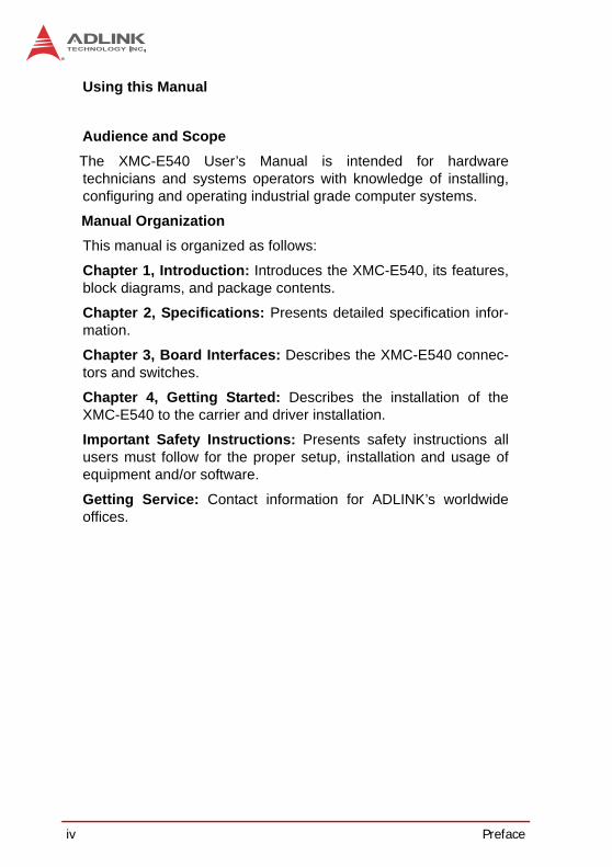
Audience and ScopeThe XMC-E540 User’s Manual is intended for hardwaretechnicians and systems operators with knowledge of installing,configuring and operating industrial grade computer systems.
Manual OrganizationThis manual is organized as follows:
Chapter 1, Introduction: Introduces the XMC-E540, its features,block diagrams, and package contents.
Chapter 2, Specifications: Presents detailed specification infor-mation.
Chapter 3, Board Interfaces: Describes the XMC-E540 connec-tors and switches.
Chapter 4, Getting Started: Describes the installation of theXMC-E540 to the carrier and driver installation.
Important Safety Instructions: Presents safety instructions allusers must follow for the proper setup, installation and usage ofequipment and/or software.
Getting Service: Contact information for ADLINK’s worldwideoffices.

Preface v
XMC-E540
ConventionsTake note of the following conventions used throughout thismanual to make sure that users perform certain tasks andinstructions properly.
NOTE:NOTE:
Additional information, aids, and tips that help users perform tasks.
CAUTION:
Information to prevent minor physical injury, component dam-age, data loss, and/or program corruption when trying to com-plete a task.
WARNING:
Information to prevent serious physical injury, component damage, data loss, and/or program corruption when trying to complete a specific task.

vi Preface
This page intentionally left blank.

vii
XMC-E540
Table of Contents
Revision History...................................................................... ii
Preface .................................................................................... iii
List of Figures ........................................................................ ix
List of Tables.......................................................................... xi
1 Introduction ........................................................................ 11.1 Overview.............................................................................. 11.2 Features............................................................................... 11.3 Block Diagram ..................................................................... 21.4 Package Contents ............................................................... 3
2 Specifications..................................................................... 52.1 XMC-E540 Module .............................................................. 52.2 Intel® Ethernet Controller X540-AT2 ................................... 62.3 Power Consumption ............................................................ 7
3 Board Interfaces................................................................. 93.1 XMC-E540 Board Layout..................................................... 93.2 Connector Pin Assignments .............................................. 10
4 Getting Started ................................................................. 134.1 Installing the Module.......................................................... 134.2 Driver Installation ............................................................... 14
Important Safety Instructions .............................................. 15
Getting Service...................................................................... 17

viii
This page intentionally left blank.

List of Figures ix
XMC-E540
List of FiguresFigure 1-1: XMC-E540 Functional Block Diagram ............................. 2Figure 3-1: XMC-E540 Board Layout................................................. 9

x List of Figures
This page intentionally left blank.

List of Tables xi
XMC-E540
List of TablesTable 2-1: XMC-E540 Power Consumption...................................... 7Table 3-1: RJ-45 10GbE Connector Pin Definitions ....................... 10Table 3-2: XMC Connector Pin Definition....................................... 11

xii List of Tables
This page intentionally left blank.

Introduction 1
XMC-E540
1 Introduction1.1 OverviewThe XMC-E540 is a dual-port 10GBASE-T Ethernet XMC modulewith equipped with an Inte® Ethernet Controller X540. Featuredare dual RJ-45 copper ports supporting 10G/1000/100BASE-Twith auto-negotiation, jumbo frames up to 15.5KB, TCP/UDP seg-mentation, IPv6 IP/TCP, IP/UDP receive checksum offload, FCoETx/Rx CRC offload, and 256KB FCoE transmit segmentation. TheXMC-E540 is compliant with the VITA 42.3-2006 XMC PCIExpress Protocol Layer Standard.
1.2 FeaturesCompliant with VITA 42.3 XMC standard with XMC.3 con-nectorDual-port Intel® 10Gigabit Ethernet Controller X540-AT210G/1G/100Mbps copper PHYs integrated on-chipJumbo frames up to 15.5KBTCP/UDP segmentation, IPv6 IP/TCP, IP/UDP receive checksum offloadFCoE Tx/Rx CRC offload, 256KB FCoE transmit segmenta-tionCompliant with PCI Express Base Specification Rev. 2.1 (5GT/s)Compatible with PCIe x1, x2, x4, x8 lanes Dual RJ-45 copper portsBackward compatible with 1000BASE-T by auto-negotiationPreboot Execution Environment (PXE) support
2 Introduction
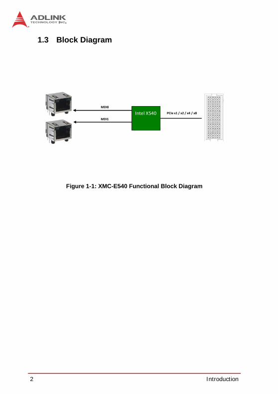
1.3 Block Diagram
Figure 1-1: XMC-E540 Functional Block Diagram
PCIe x1 / x2 / x4 / x8
MDI0
MDI1
Intel X540
Introduction 3
XMC-E540
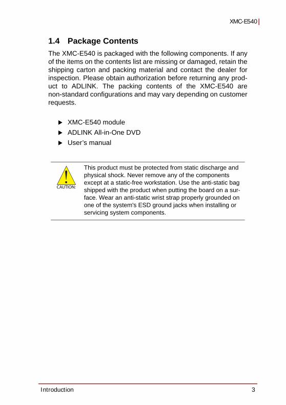
1.4 Package Contents The XMC-E540 is packaged with the following components. If anyof the items on the contents list are missing or damaged, retain theshipping carton and packing material and contact the dealer forinspection. Please obtain authorization before returning any prod-uct to ADLINK. The packing contents of the XMC-E540 arenon-standard configurations and may vary depending on customerrequests.
XMC-E540 module ADLINK All-in-One DVDUser’s manual
CAUTION:
This product must be protected from static discharge and physical shock. Never remove any of the components except at a static-free workstation. Use the anti-static bag shipped with the product when putting the board on a sur-face. Wear an anti-static wrist strap properly grounded on one of the system's ESD ground jacks when installing or servicing system components.

4 Introduction
This page intentionally left blank.

Specifications 5
XMC-E540
2 Specifications2.1 XMC-E540 Module
Standards VITA 42.3-2006 XMC PCI Express Protocol Layer StandardForm Factor • IEEE P1386, Standard XMC.3
• 74 mm x 149 mm x 8.2 mm (single width)Controller Intel® Ethernet Controller X540-AT2
• Dual port 100Mb/1000Mb/10Gb data rate• Intel® Virtualization Technology for Connectivity (VMDq,
SR-IOV)• Fiber Channel over Ethernet• MACsec IEEE 802.1 AE• IEEE 1588• Intel® Data Direct I/O Technology• Intelligent Offloads• Storage Over Ethernet (iSCSI, FCoE, NFS)
Interface • PCI Express base specification 2.1 (2.5GT/s or 5GT/s)• Supports PCI Express x1, x4, x8 lanes• 64-bit address support for systems using more than 4 GB
of physical memoryI/O • Two RJ-45 10G/1000/100BASE-T ports
• Auto-negotiation of 10 Gb/s, 1 Gb/s, 100Mb/s modeOS Compatibility
• Microsoft Windows 7 64-bit• Microsoft® Windows® Server 2003 R2 (32-bit x86)• Microsoft® Windows® Server 2008 64-bit• Red Hat Enterprise Linux 6 x86• Other OS support upon request
Environmental • Operating Temperature: 0°C to 60°C (with forced air flow)• Storage Temperature: -40°C to 85°C• Humidity: 95%@60°C non-condensing• Vibration: Operating 2Grms, 5-500Hz
EMI • CE EN55022• FCC Class A
NOTE:NOTE:
Specifications are subject to change without prior notice.
6 Specifications
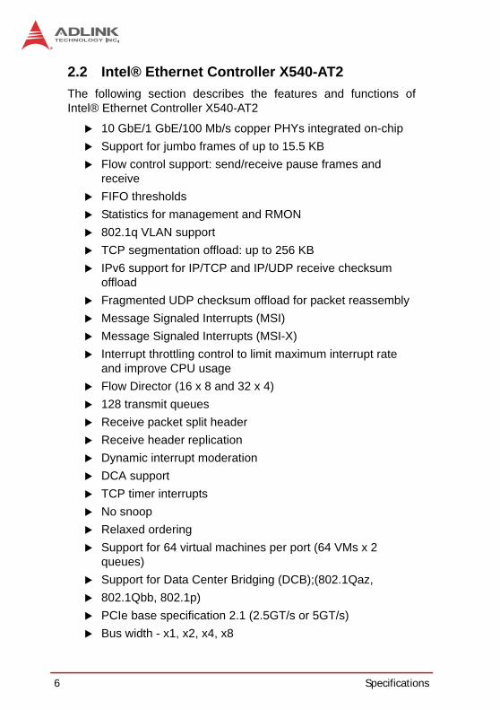
2.2 Intel® Ethernet Controller X540-AT2The following section describes the features and functions ofIntel® Ethernet Controller X540-AT2
10 GbE/1 GbE/100 Mb/s copper PHYs integrated on-chipSupport for jumbo frames of up to 15.5 KBFlow control support: send/receive pause frames and receive FIFO thresholdsStatistics for management and RMON802.1q VLAN supportTCP segmentation offload: up to 256 KBIPv6 support for IP/TCP and IP/UDP receive checksum offloadFragmented UDP checksum offload for packet reassemblyMessage Signaled Interrupts (MSI)Message Signaled Interrupts (MSI-X)Interrupt throttling control to limit maximum interrupt rate and improve CPU usageFlow Director (16 x 8 and 32 x 4)128 transmit queuesReceive packet split headerReceive header replicationDynamic interrupt moderationDCA supportTCP timer interruptsNo snoopRelaxed orderingSupport for 64 virtual machines per port (64 VMs x 2 queues)Support for Data Center Bridging (DCB);(802.1Qaz, 802.1Qbb, 802.1p)PCIe base specification 2.1 (2.5GT/s or 5GT/s)Bus width - x1, x2, x4, x8
Specifications 7
XMC-E540
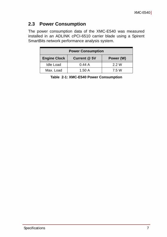
2.3 Power ConsumptionThe power consumption data of the XMC-E540 was measuredinstalled in an ADLINK cPCI-6510 carrier blade using a SpirentSmartBits network performance analysis system.
Table 2-1: XMC-E540 Power Consumption
Power Consumption
Engine Clock Current @ 5V Power (W)
Idle Load 0.44 A 2.2 WMax. Load 1.50 A 7.5 W

8 Specifications
This page intentionally left blank.
Board Interfaces 9
XMC-E540
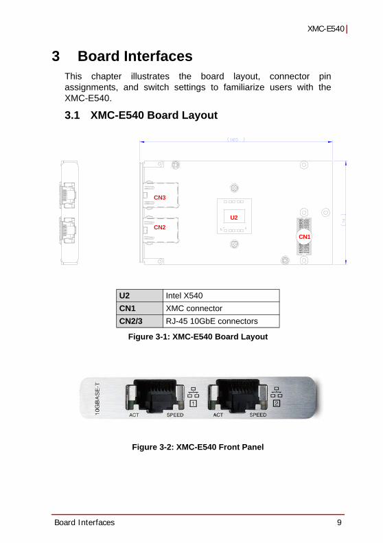
3 Board InterfacesThis chapter illustrates the board layout, connector pinassignments, and switch settings to familiarize users with theXMC-E540.
3.1 XMC-E540 Board Layout
Figure 3-1: XMC-E540 Board Layout
Figure 3-2: XMC-E540 Front Panel
U2 Intel X540CN1 XMC connectorCN2/3 RJ-45 10GbE connectors
CN2 CN1
U2
CN3

10 Board Interfaces
3.2 Connector Pin Assignments
RJ-45 10G Ethernet Connectors (CN2/3)
Table 3-1: RJ-45 10GbE Connector Pin Definitions
Pin # 100BASE-TX 10G/1000BASE-T
1 TX+ LAN_TX0+2 TX- LAN_TX0-3 RX+ LAN_TX1+4 -- LAN_TX2+5 -- LAN_TX2-6 RX- LAN_TX1-7 -- LAN_TX3+8 -- LAN_TX3+
Status ACT SPEED
Network link is not established or system powered off Off Off
100 Mbps (100BASE-T)
Link On (Green)Off
Active Blinking
1000 Mbps (1000BASE-TX)
Link On (Green)Yellow
Active Blinking
10 Gbps (10GBASE-T)
Link On (Green)Blue
Active Blinking
81
ACT SPEED

Board Interfaces 11
XMC-E540
XMC Connector (CN1)
Table 3-2: XMC Connector Pin Definition
Pin# A B C D E F1 PET0p0 PET0n0 3.3V PET0p1 PET0n1 VPWR2 GND GND Reserved GND GND MRSTI#3 PET0p2 PET0n2 3.3V PET0p3 PET0n3 VPWR4 GND GND Reserved GND GND Reserved5 PET0p4 PET0n4 3.3V PET0p5 PET0n5 VPWR6 GND GND Reserved GND GND NC7 PET0p6 PET0n6 3.3V PET0p7 PET0n7 VPWR8 GND GND NC GND GND NC9 NC NC NC NC NC VPWR
10 GND GND NC GND GND Reserved11 PER0p0 PER0n0 Reserved PER0p1 PER0n1 VPWR12 GND GND Reserved GND GND MPRESENT#13 PER0p2 PER0n2 Reserved PER0p3 PER0n3 VPWR14 GND GND Reserved GND GND Reserved15 PER0p4 PER0n4 N.C. PER0p5 PER0n5 VPWR16 GND GND Reserved GND GND Reserved17 PER0p6 PER0n6 N.C. PER0p7 PER0n7 N.C.18 GND GND N.C. GND GND N.C.19 REFCLK+0 REFCLK-0 N.C. N.C. N.C. N.C.
A19A1
F19F1

12 Board Interfaces
This page intentionally left blank.
Getting Started 13
XMC-E540
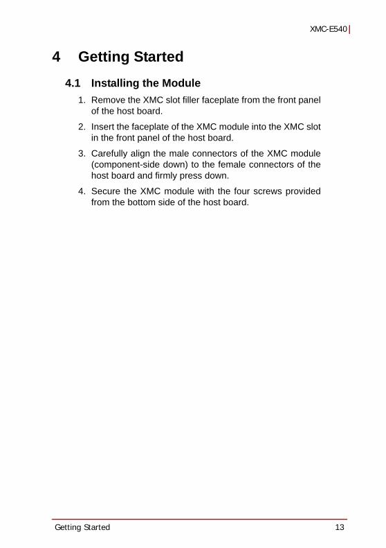
4 Getting Started4.1 Installing the Module
1. Remove the XMC slot filler faceplate from the front panelof the host board.
2. Insert the faceplate of the XMC module into the XMC slotin the front panel of the host board.
3. Carefully align the male connectors of the XMC module(component-side down) to the female connectors of thehost board and firmly press down.
4. Secure the XMC module with the four screws providedfrom the bottom side of the host board.

14 Getting Started
4.2 Driver InstallationThe XMC-E540 drivers can be found on the ADLINK All-In-OneDVD at X:\XMC\XMC-E540\LAN, or at the ADLINK website (http://www.adlinktech.com). Driver installation procedures for Win-dows 7 are described below.
1. Install the Windows operating system before installing anydriver. Most standard I/O device drivers are installed duringWindows installation.
2. Install the LAN drivers by extracting and running the execut-able file in ...\LAN\Intel_Network_Adapter_AllOS_v16.6.zip
We recommend using the drivers provided on the ADLINKAll-in-One DVD or downloaded from the ADLINK website toensure compatibility.

Important Safety Instructions 15
XMC-E540
Important Safety Instructions
For user safety, please read and follow all instructions,WARNINGS, CAUTIONS, and NOTES marked in this manualand on the associated equipment before handling/operating theequipment.
Read these safety instructions carefully.Keep this user’s manual for future reference.Read the specifications section of this manual for detailed information on the operating environment of this equipment.When installing/mounting or uninstalling/removing equipment:
Turn off power and unplug any power cords/cables.To avoid electrical shock and/or damage to equipment:
Keep equipment away from water or liquid sources;Keep equipment away from high heat or high humidity;Keep equipment properly ventilated (do not block or cover ventilation openings);Make sure to use recommended voltage and power source settings;Always install and operate equipment near an easily accessible electrical socket-outlet;Secure the power cord (do not place any object on/over the power cord);Only install/attach and operate equipment on stable surfaces and/or recommended mountings; and,If the equipment will not be used for long periods of time, turn off and unplug the equipment from its power source.

16 Important Safety Instructions
Never attempt to fix the equipment. Equipment should only be serviced by qualified personnel.
A Lithium-type battery may be provided for uninterrupted, backupor emergency power.
Equipment must be serviced by authorized technicians when:
The power cord or plug is damaged;Liquid has penetrated the equipment;It has been exposed to high humidity/moisture;It is not functioning or does not function according to the user’s manual;It has been dropped and/or damaged; and/or,It has an obvious sign of breakage.
WARNING:
Risk of explosion if battery is replaced with one of an incorrect type. Dispose of used batteries appropriately.

Getting Service 17
XMC-E540
Getting Service
Contact us should you require any service or assistance.
ADLINK Technology, Inc. Address: 9F, No.166 Jian Yi Road, Zhonghe District New Taipei City 235, Taiwan
166 9Tel: +886-2-8226-5877 Fax: +886-2-8226-5717 Email: [email protected]
Ampro ADLINK Technology, Inc. Address: 5215 Hellyer Avenue, #110, San Jose, CA 95138, USA Tel: +1-408-360-0200 Toll Free: +1-800-966-5200 (USA only) Fax: +1-408-360-0222 Email: [email protected]
ADLINK Technology (China) Co., Ltd. Address: 300 (201203) 300 Fang Chun Rd., Zhangjiang Hi-Tech Park,
Pudong New Area, Shanghai, 201203 China Tel: +86-21-5132-8988 Fax: +86-21-5132-3588 Email: [email protected]
ADLINK Technology Beijing Address: 1 E 801 (100085)
Rm. 801, Power Creative E, No. 1, B/D Shang Di East Rd., Beijing, 100085 China
Tel: +86-10-5885-8666 Fax: +86-10-5885-8626 Email: [email protected]
ADLINK Technology Shenzhen Address:
A1 2 C (518057) 2F, C Block, Bldg. A1, Cyber-Tech Zone, Gao Xin Ave. Sec. 7, High-Tech Industrial Park S., Shenzhen, 518054 China
Tel: +86-755-2643-4858 Fax: +86-755-2664-6353 Email: [email protected]
LiPPERT ADLINK Technology GmbH Address: Hans-Thoma-Strasse 11, D-68163, Mannheim, Germany Tel: +49-621-43214-0 Fax: +49-621 43214-30 Email: [email protected]

18 Getting Service
ADLINK Technology, Inc. (French Liaison Office) Address: 15 rue Emile Baudot, 91300 Massy CEDEX, France Tel: +33 (0) 1 60 12 35 66 Fax: +33 (0) 1 60 12 35 66 Email: [email protected]
ADLINK Technology Japan Corporation Address: 101-0045 3-7-4
374 4F KANDA374 Bldg. 4F, 3-7-4 Kanda Kajicho, Chiyoda-ku, Tokyo 101-0045, Japan
Tel: +81-3-4455-3722 Fax: +81-3-5209-6013 Email: [email protected]
ADLINK Technology, Inc. (Korean Liaison Office) Address: 1675-12 8
8F Mointer B/D,1675-12, Seocho-Dong, Seocho-Gu, Seoul 137-070, Korea
Tel: +82-2-2057-0565 Fax: +82-2-2057-0563 Email: [email protected]
ADLINK Technology Singapore Pte. Ltd. Address: 84 Genting Lane #07-02A, Cityneon Design Centre,
Singapore 349584 Tel: +65-6844-2261 Fax: +65-6844-2263 Email: [email protected]
ADLINK Technology Singapore Pte. Ltd. (Indian Liaison Office) Address: 1st Floor, #50-56 (Between 16th/17th Cross) Margosa Plaza,
Margosa Main Road, Malleswaram, Bangalore-560055, India Tel: +91-80-65605817, +91-80-42246107 Fax: +91-80-23464606 Email: [email protected]
ADLINK Technology, Inc. (Israeli Liaison Office) Address: 6 Hasadna St., Kfar Saba 44424, Israel Tel: +972-9-7446541 Fax: +972-9-7446542 Email: [email protected]