Dual Nano Switch - Aeotec › pub › media › manuals › Aeotec-Z... · 2018-03-18 · Reset...
18
View the expanded manual: http://aeotec.com/support Dual Nano Switch IMPORTANT! This product has been fully tested and certified to work with Z-Wave by the Z-Wave Alliance. It is crafted using Z-Wave Plus, the latest device version of Z-Wave. As such, if the product does not work with your gateway, please be sure to check with your gateway manufacturer that they have integrated this device with their gateway for full operation.
Transcript of Dual Nano Switch - Aeotec › pub › media › manuals › Aeotec-Z... · 2018-03-18 · Reset...

View the expanded manual:http://aeotec.com/support
Dual Nano Switch
IMPORTANT!This product has been fully tested and certified to work with Z-Wave by the Z-Wave Alliance. It is crafted using Z-Wave Plus, the latest device version of Z-Wave. As such, if the product does not work with your gateway, please be sure to check with your gateway manufacturer that they have integrated this device with their gateway for full operation.

Aeotec by Aeon Labs Dual Nano Switch.
Aeotec Dual Nano Switch is a low-cost Z-Wave Switch specifically used to enable Z-Wave command and control (on/off) of any wall switches. It can report immediate wattage consumption or kWh energy usage over a period of time. In the event of power failure, non-volatile memory retains all programmed information relating to the unit’s operating status.
It can connect to 2 external manual switches to control the load ON/OFF independently. Its surface has a pin socket, which can be used for connecting to the touch panel, so you can also use the touch panel to control the Dual Nano Switch.
The Dual Nano Switch is also a security Z-Wave device and supports Over The Air (OTA) feature for the products firmware upgrade.
132
1
Z-Wave and Z-Wave Plus areregistered trademarks of SigmaDesigns and its subsidiaries in the United States and other countries
FCC ID: XBAFT132
Certifications (regional):
Version: 501013200001-AA www.aeotec.com
Contact your local government for information regarding the collection systems available.

2 31
(Front)
Action Button
Touch panel connection port
RGB LED
RF antenna
Fastening screws
Familiarize yourself with your Dual Nano Switch.
2
(Back)
(Bottom)
Wire connection port
Do not dispose of electrical appliances as unsorted municipal waste, use separate collection facilities.
Warning
Connect the equipment into an outlet on a circuit different from that to which the receiver is connected.Consul the dealer or an experienced radio/TV technician for help.
UL NOTICE (For USA).Install only in a UL listed junction box sized 3×2×2.75 inch (75×50×70 mm) or larger, minimum volume 14 in (230 cm ).Use Copper Conductors Only.“CAUTION – Risk of Electric Shock – More than one disconnect switch may be required to de-energize the equipment before servicing”.“WARNING - This device shall not be used in combination with a wall switch controlling a receptacle.”
1.
2.3.
4.
3 3

330
N – Power input for neutralL – Power input for liveIN – Input for load power supplyOUT1 – Output for load 1OUT2 – Output for load 2S1 – External switch control for load 1S2 – External switch control for load 2
Notes for the wire connection ports:
Touch panelLN IN OUT1 OUT2 S1 S2
found to comply with the limits for a Class B digital device, pursuant to part 15 of the FCC Rules. These limits are designed to provide reasonable protection against harmful interference in a residential installation. This equipment generates, uses and can radiate radio frequency energy and, if not installed and used in accordance with the instructions, may cause harmful interference to radio communications. However, there is no guarantee that interference will not occur in a particular installation. If this equipment does cause harmful interference to radio or television reception, which can be determined by turning the equipment off and on, the user is encouraged to try to correct the interference by one or more of the following measures:
Reorient or relocate the receiving antenna.Increase the separation between the equipment and receiver.

4 29
Install the Dual Nano Switch.
1. Shut off the main circuit breaker of your home for safety during the installation and ensure the wires are not short circuited during the installation which will cause damage to the Dual Nano Switch.
Important: A licensed electrician with knowledge and understanding electrician systems and electrical safety should complete the electrical installation.
Note: Your home’s main circuit breaker must support the overload protection for safety.
FCC NOTICE (for USA)THE MANUFACTURER IS NOT RESPONSIBLE FOR ANY RADIO OR TV INTERFERENCE CAUSED BY UNAUTHORIZED MODIFICATIONS TO THIS EQUIPMENT.SUCH MODIFICATIONS COULD VOID THE USER’S AUTHORITY TO OPERATE THE EQUIPMENT.
STORE INDOORS WHEN NOT IN USE. SUITABLE FOR DRY LOCATIONS. DO NOT IMMERSE IN WATER. NOT FOR USE WHERE DIRECTLY EXPOSED TO WATER.
This device complies with Part 15 of the FCC Rules. Operation is subject to the following two conditions:
This device may not cause harmful interference, and This device must accept any interference received, including interference that may cause undesired operation. This equipment has been tested and
1.
2.

28
Cut wire if neccessary
0.27"(5mm)
Strip Gage (measure barehere)
5
Preparing connection wires14 AWG power wires for Input/ Output. 18 AWG copper wires for external manual switch.Use the wire stripper cut the metallic part of the connection wire and make sure the length of the metallic part is about 5mm.
2.
Note: All connection wires needs to be flexible cable.
USE OF THE PRODUCTS, WHETHER BASED ON NEGLIGENCE, STRICT LIABILITY, BREACH OF WARRANTY, BREACH OF AGREEMENT, OR EQUITABLE PRINCIPLES, IS EXPRESSLY LIMITED TO, AT AEON LABS' OPTION, REPLACEMENT OF, OR REPAYMENT OF THE PURCHASE PRICE FOR THAT PORTION OF PRODUCTS WITHRESPECT TO WHICH DAMAGES ARE CLAIMED. ALL CLAIMS OF ANY KIND ARISING IN CONNECTION WITH THIS AGREEMENT OR THE SALE OR USE OF PRODUCTS SHALL BE DEEMED WAIVED UNLESS MADE IN WRITING WITHIN THIRTY (30) DAYS FROM AEON LABS' DELIVERY, OR THE DATE FIXED FOR DELIVERY IN THE EVENT OF NONDELIVERY. THE INDEMNITY AND WARRANTY IN ABOVE ARE EXCLUSIVE AND IN LIEU OF ALL OTHER INDEMNITIES OR WARRANTIES, WHETHER EXPRESS OR IMPLIED, INCLUDING THE IMPLIED WARRANTIES OF MERCHANTABILITY AND FITNESS FOR A PARTICULAR PURPOSE.

6 27
Wiring diagram of AC120V/230V power input.
L Touch panel
Live
NeutralAC120V~230V
N IN OUT1 OUT2 S1 S2
or relating to any actual or alleged infringement or misappropriation of any patent, trademark, mask work, copyright, trade secret or any actual or alleged violation of any other intellectual property rights arising from or in connection with the products, except to the extent that such infringement exists as a result of Aeon Labs' manufacturing processes.
IN NO EVENT SHALL AEON LABS BE LIABLE FOR ANY INDIRECT, INCIDENTAL, PUNITIVE, SPECIAL OR CONSEQUENTIAL DAMAGES, OR DAMAGES FOR LOSS OF PROFITS, REVENUE, OR USE INCURRED BYCUSTOMER, COMPANY OR ANY THIRD PARTY, WHETHER IN AN ACTION IN CONTRACT, OR TORT, OR OTHERWISE EVENIF ADVISED OF THE POSSIBILITY OF SUCH DAMAGES. AEON LABS' LIABILITY AND CUSTOMER'S EXCLUSIVE REMEDY FOR ANY CAUSE OF ACTION ARISING IN CONNECTION WITH THIS AGREEMENT OR THE SALE OR

726
needs, Company must prepay shipping and transportation charges for returned Products, and insure the shipment or accept the risk of loss or damage during such shipment and transportation. Aeon Labs will ship the repaired or replacement products to Company freight prepaid.Customer and Company shall indemnify, defend, and hold Aeon Labs and Aeon Labs' affiliates, shareholders, directors, officers, employees, contractors, agents and other representatives harmless from all demands, claims, actions, causes of action, proceedings, suits, assessments, losses, damages, liabilities, settlements, judgments, fines, penalties, interest, costs and expenses (including fees and disbursements of counsel) of every kind (i) based upon personal injury or death or injury to property to the extent any of the foregoing is proximately caused either by a defective product (including strict liability in tort) or by the negligent or willful acts or omissions of Customer or its officers, employees, subcontractors or agents, and/or (ii) arising from

8 25
Wiring diagram of DC24V power input.Since the Dual Nano Switch also supports the DC24V power input, so you can use it to control the loads that powered by DC24V.
-
+
LN IN OUT1OUT2 S1 S2 Touch panel
DC 24V
Any repairs under this warranty must be conducted by an authorized Aeon Labs service representative and under Aeon Labs' RMA policy. Any repairs conducted by unauthorized persons shall void this warranty.
Excluded from the warranty are problems due to accidents, acts of God, civil or military authority, civil disturbance, war, strikes, fires, other catastrophes, misuse, misapplication, storage damage, negligence, electrical power problems, or modification to the Products or its components.
Aeon Labs does not authorize any person or party to assume or create for it any other obligation or liability in connection with the Products except as set forth herein. Aeon Labs will pass on to Company all manufacturers’ Material warranties to the extent that they are transferable, but will not independently warrant any Material. Company will assist Customer with all warranty, repair, return and technical support

924
Aeon Labs warrants to the original purchaser of Products, that is the Company who you have purchased from, that for the Warranty Period (as defined below), the Products will be free from material defects in materials and workmanship. The foregoing warranty is subject to the proper installation, operation and maintenance of the Products in accordance with installation instructions and the operating manual supplied. Warranty claims must be made to the Company who you have purchased from in writing within thirty (30) days of the manifestation of a problem.
Aeon Labs' sole obligation under the foregoing warranty is, at Aeon Labs' option, to repair, replace or correct any such defect that was present at the time of delivery, or to remove the Products and to refund the purchase price to Company.
The Warranty Period begins on the date the Products is delivered and continues for 12 months.

All above wiring diagrams show that the Dual Nano Switch uses 2-Way or momentary button switches as the external manual switch for 2-Way connection.
10 23
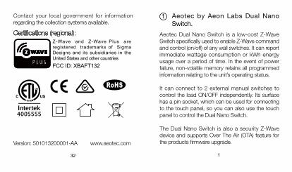
The below diagram will show you that the Dual Nano Switch uses the SPDT (Single-Pole Double-Throw) switches as the external manual switch for 3-Way connection.
Note: The “IN” terminal should be connected to the “Live” of AC 120V/230V power wire.
Wiring diagram of 3-Way connection for the external manual switch.
Operating temperature: 0℃ to 40℃ /32 ℉ to 104 ℉ .Relative humidity: 8% to 80%.Operating distance: Up to 492 feet/150 meters outdoors.
Warranty.7If you are in need of any technical support during or subsequent to your products’ warranty, please get in touch with our support team via http://aeotec.com/support. The Company you bought this product from has also guaranteed to assist you with any of your support needs, and you can also contact them for accordingly.
This guarantee made by the company who you purchased the product from includes the transfer of Aeon Labs’ full warranty to that Company. They’ve guaranteed that they’ll be able to assist you, the Customer, with all technical support and repair needs on our behalf.
1122
N Touch panel
Live
NeutralAC120V~230V
3-Way Switch(SPDT)
L IN OUT1OUT2 S1 S2
Install Dual Nano Switch to the gang box.3.
Live/Hot wire connection: Connect the Live/Hot wire to the “L” terminal on the Dual Nano Switch.
a.
Model number: ZW132/ZW140Power input: 120VAC to 240VAC, 50Hz to 60Hz.Rated output: 6.5A per channel for resistive load. Total current: Max 10A. Max standby power: 0.8W.
6 Technical specifications.
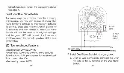
Reset your Dual Nano Switch.If at some stage, your primary controller is missing or inoperable, you may wish to reset all of your Dual Nano Switch’s settings to their factory defaults. To do this, press and hold the Action Button for 20 seconds and then release it. Your Dual Nano Switch will now be reset to its original settings, and the green LED will be solid for 2 seconds and then remain the colourful gradient status as a confirmation.
colourful gradient, repeat the instructions above from step 1.

12 21
Neutral wire connection: Connect the Neutral wire to the “N” terminal on the Dual Nano Switch.Load wire connection: Connect the 2 Load wires to the “OUT1” and “OUT2” on the Dual Nano Switch.External/manual Switch connection: Connect 2 18AWG wires to the “S1” and “S2” on the Dual Nano Switch.External/manual Switch connection: Connect 2 18AWG wires form the 2 terminals on the External/manual Switch to the Live wire.
b.
c.
d.
e.
LN IN OUT1 OUT2S1 S2
Set your Z-Wave Plus controller into pairing mode.Press the Action Button 2 times within 1 second on the Dual Nano Switch, the blue LED (secure indication) will blink to indicate the Dual Nano Switch is entering into secure pairing mode.If the Dual Nano Switch has been successfully added to your Z-Wave network, its RGB LED will be solid. If the pairing was unsuccessful, the red LED will be on for 2 seconds and then remain a
Including Dual Nano Switch as a secure device:In order to take full advantage of the Dual Nano Switch, you will want your Dual Nano Switch as a security device that uses encrypted messages to communicate in your Z-wave network. A security enabled controller/gateway (or Z-Wave Plus controller) is required.
1.
2.
3.a
b
c
d
e
solid indication. If inclusion is unsuccessful, the red LED will be on for 2 seconds and then return to a colourful gradient.

13
Mounting the gang box.4.Position all wires to provide room for the device. Place the Dual Nano Switch inside the gang box towards the back of the box. Position the antenna towards the back of the box, away from all other wiring.Reinstall the Dual Nano Switch to the gang box.Reinstall the cover onto the gang box.
a.
b.
c.
d.
20
Note: This is the physical connection diagram for AC120V/230V power input.
Security or Non-security feature of your Dual Nano Switch in Z-Wave network.Including Dual Nano Switch as a non-secure device:If you want your Dual Nano Switch as a non-secure device in your Z-Wave network, press the Action Button once on Dual Nano Switch when you pair it to your gateway. If inclusion is successful, the green LED will be on for 2 seconds, and then return to a
commands supporting energy monitoring are the Meter Command Class. Automatic reports are sent to association group 1, which is setup via the Association Command Class.) Please consult the operation manual for these control points for specific instructions on monitoring the Dual Nano Switch.
1 2 3
Note: The model ZW140 Dual Nano Switch does not have the ability to monitor energy consumption. The model ZW132 Dual Nano Switch supports the energy metering feature and you can see the words “with Energy Metering” on its packaging box.

14 19
Restore Power.Restore power at the circuit breaker or fuse.
5.
ON
ON
ON
ON
ON ON
ON
ON
ON
ON
Note:The gang box should be sized 3×2×2.75 inch/ 75×50×70 mm or larger, minimum volume 14 in / 230cm .Use flexible copper conductors only.
a.
b.
3 3
Monitoring Energy Consumption.
The Aeotec Dual Nano Switch can report wattage energy usage or kWh energy usage to a Z-Wave control point when requested. If this function is supported by the control points, the energy consumption will be displayed in the user interface of the control points. (The specific Z-Wave
Dual Nano Switch through the Touch panel directly.

1518
After your Dual Nano Switch is installed and powered on, you are now able to manually control the Dual Nano Switch to turn it On/Off directly via pressing your Dual Nano Switch’s Action Button, it is time to add your Dual Nano Switch to the Z-Wave network. To set your Z-Wave gateway/controller into pairing mode, please refer to the respective section within your controller instruction manual.
3
Adding your Dual Nano Switch to a Z-Wave network.
Quick start.
Set your Z-Wave controller into pairing mode. Press the Action Button on the Dual Nano Switch or toggle the external manual switch once, the green LED (non-secure indication) will blink to indicate the Dual Nano Switch is entering into pairing mode.
1.2.
You can also set the external switch mode through Configuration Command Class. Parameter 120 [1 byte dec] is the parameter that will set one of the 3 different modes. If you set this configuration to:
(0) 2-state switch mode(1) Momentary push button Mode(2) 3-way switch mode
manual switch wired into Dual Nano Switch, toggle the button on the manual switch once and wait 2 seconds for the Dual Nano Switch to detect the type of manual switch.
Touch panel control.
As you can see that the Dual Nano Switch’s surface has a pin port, this port is used to connect the Touch panel. When you have already connected it to the Dual Nano Switch, you will be possible to control the

16
5 Advanced functions.Changing mode on the External Switch/Button Control.The Dual Nano Switch can be controlled via 2-state (flip/flop) external/manual switch, momentary push button or the 3-way switch. To automatically detect and set the mode to the appropriate type of
17
If the Dual Nano Switch has been successfully added to your Z-Wave network, its RGB LED will be solid. If the pairing was unsuccessful, the red LED will be on for 2 seconds and then remain a colourful gradient, repeat the instructions above from step 1.
With your Dual Nano Switch now working as a part of your smart home, you’ll be able to configure it from your home control software/phone application. Please refer to your software’s user guide for further instructions on configuring Dual Nano Switch to your needs.
4 Removing Dual Nano Switch from a Z-Wave network.
Your Dual Nano Switch can be removed from your Z-Wave network at any time. You’ll need to use your Z-Wave network’s main controller. To set your Z-Wave controller/gateway into removal mode, please refer to the respective section within your
Set your Z-Wave controller into removal mode. Press the Action Button on the Dual Nano Switch or toggle the external manual switch 3 times in fast succession.If the Dual Nano Switch has been successfully removed from your Z-Wave network, its RGB LED will remain colourful gradient. If the removal was unsuccessful, the RGB LED will still be solid (following the state of the output load), repeat the instructions above from step 1.
1.2.
3.
controller instruction manual.3.