
Dual Converter using Thyristors
20
Dual Converter using Thyristors
-
Upload
anjalibajipai -
Category
Documents
-
view
244 -
download
1
description
Dual converter is a power electronics control system to get either polarity DC from AC rectification by forward converter and reverse converter . It can run a DC motors in either direction with speed control too.
Transcript of Dual Converter using Thyristors

Dual Converter using Thyristors
http://www.edgefxkits.com/
Introduction
Dual Converter using Thyristors
A.C. motors have the great advantages of being relatively inexpensive and very reliable.
Induction motors in particular are very robust and therefore used in many domestic appliances such as washing machines, vacuum cleaners, water pumps, and others.
The induction motor may be regarded as practically a constant-speed machine, the difficulty of varying its speed economically constitutes one of its main disadvantages.
This drawback is overcome by using a thyristor controlled cyclo converter that enables the speed to be lowered in steps by Microcontroller triggering a SCR bank of 8nos in F/2 & F/3.
http://www.edgefxkits.com/
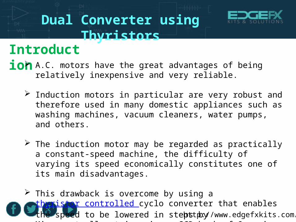
Project Block Diagram
http://www.edgefxkits.com/
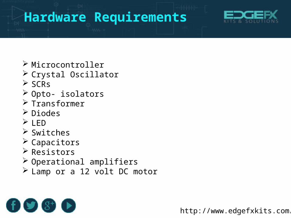
Hardware Requirements
Microcontroller Crystal Oscillator SCRs Opto- isolators Transformer Diodes LED Switches Capacitors Resistors Operational amplifiers Lamp or a 12 volt DC motor
http://www.edgefxkits.com/
Software Requirements
Keil Compiler
Keil an ARM Company makes C compilers, macro assemblers, real-time kernels, debuggers, simulators, integrated environments, evaluation boards, and emulators for ARM7/ARM9/Cortex-M3, XC16x/C16x/ST10, 251, and 8051 MCU families.
Languages: Embedded C or Assembly

http://www.edgefxkits.com/
Power Supply
230 V AC 50 Hz
5V DC
12V step down
Bridge rectifier Filter(470µf) 5v Regulator

http://www.edgefxkits.com/
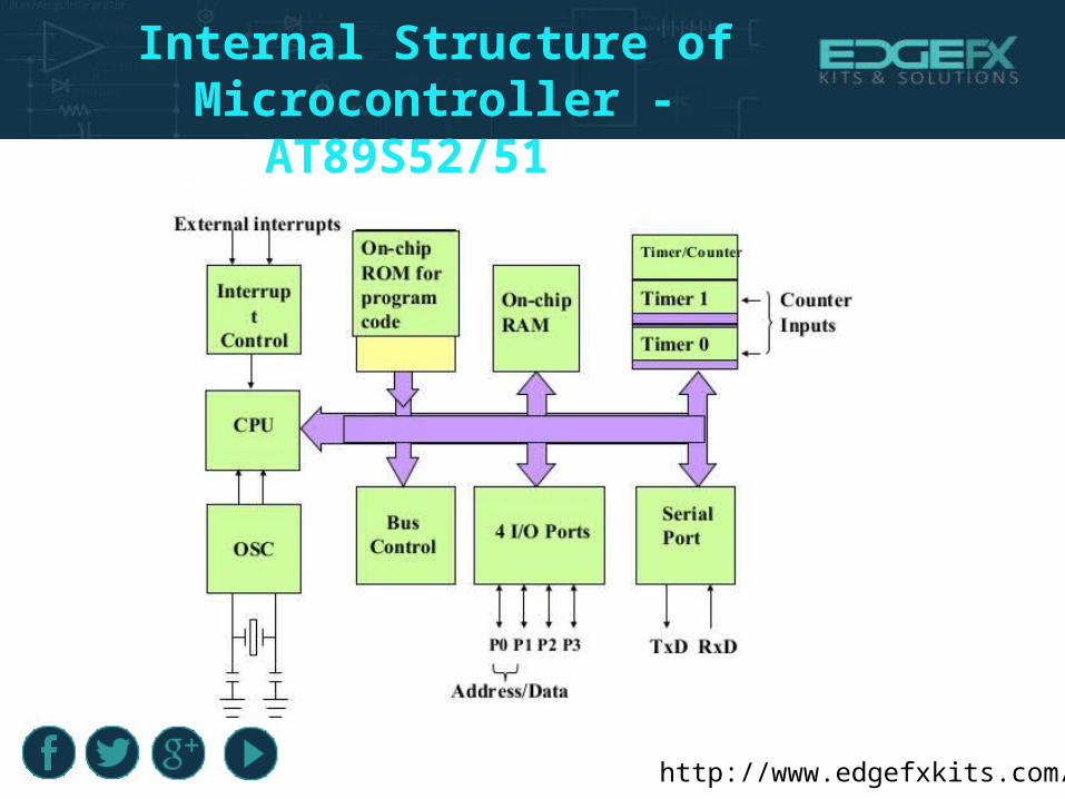
Which Microcontroller is Used in this Project?
A 40 pin microcontroller from 8051 family is used in this project.
It is a smaller computer
Has on-chip RAM, ROM, I/O ports...
http://www.edgefxkits.com/
Internal Structure of Microcontroller - AT89S52/51
http://www.edgefxkits.com/
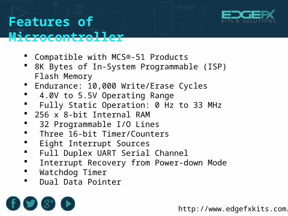
Features of Microcontroller
Compatible with MCS®-51 Products 8K Bytes of In-System Programmable (ISP) Flash Memory Endurance: 10,000 Write/Erase Cycles 4.0V to 5.5V Operating Range Fully Static Operation: 0 Hz to 33 MHz 256 x 8-bit Internal RAM 32 Programmable I/O Lines Three 16-bit Timer/Counters Eight Interrupt Sources Full Duplex UART Serial Channel Interrupt Recovery from Power-down Mode Watchdog Timer Dual Data Pointer
http://www.edgefxkits.com/
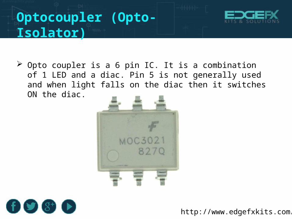
Optocoupler (Opto-Isolator)
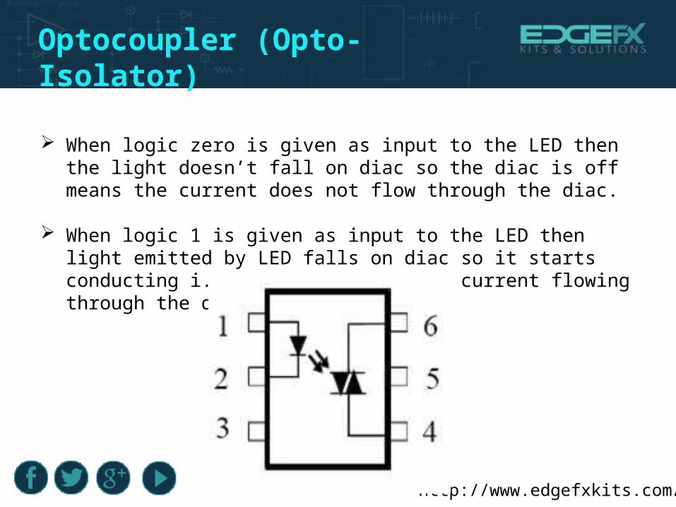
Opto coupler is a 6 pin IC. It is a combination of 1 LED and a diac. Pin 5 is not generally used and when light falls on the diac then it switches ON the diac.
http://www.edgefxkits.com/
When logic zero is given as input to the LED then the light doesn’t fall on diac so the diac is off means the current does not flow through the diac.
When logic 1 is given as input to the LED then light emitted by LED falls on diac so it starts conducting i.e., now there will be current flowing through the diac.
Optocoupler (Opto-Isolator)
http://www.edgefxkits.com/
Three Phase Induction Motor
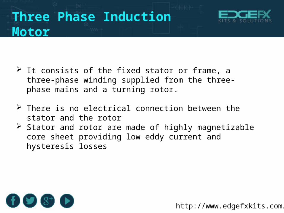
It consists of the fixed stator or frame, a three-phase winding supplied from the three-phase mains and a turning rotor.
There is no electrical connection between the stator and the rotor Stator and rotor are made of highly magnetizable core sheet providing
low eddy current and hysteresis losses
http://www.edgefxkits.com/
Stator And Rotor
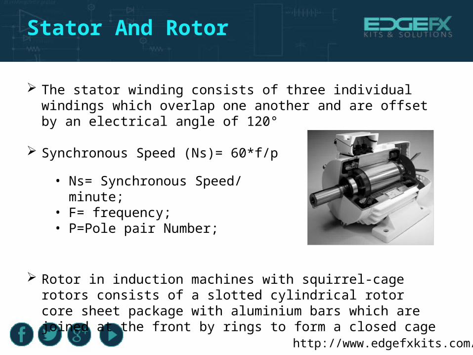
The stator winding consists of three individual windings which overlap one another and are offset by an electrical angle of 120°
Synchronous Speed (Ns)= 60*f/p
Rotor in induction machines with squirrel-cage rotors consists of a slotted cylindrical rotor core sheet package with aluminium bars which are joined at the front by rings to form a closed cage
• Ns= Synchronous Speed/ minute;• F= frequency;• P=Pole pair Number;
http://www.edgefxkits.com/
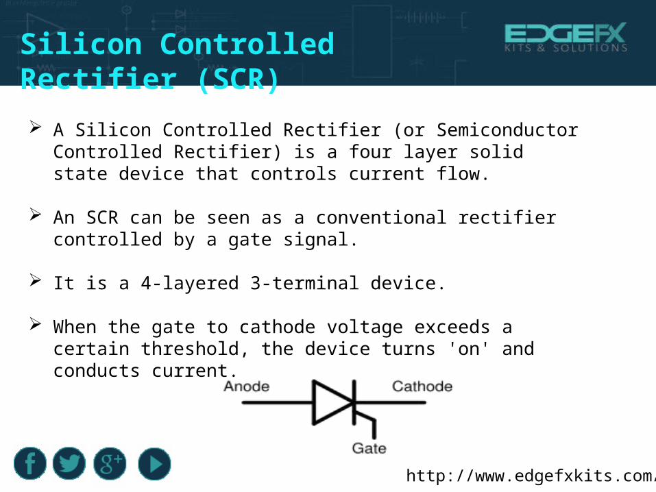
Silicon Controlled Rectifier (SCR) A Silicon Controlled Rectifier (or Semiconductor Controlled Rectifier) is
a four layer solid state device that controls current flow.
An SCR can be seen as a conventional rectifier controlled by a gate signal.
It is a 4-layered 3-terminal device.
When the gate to cathode voltage exceeds a certain threshold, the device turns 'on' and conducts current.

http://www.edgefxkits.com/
Silicon Controlled Rectifier (SCR)
The operation of a SCR can be understood in terms of a pair of tightly coupled Bipolar Junction Transistors.
SCR has three states:
Reverse blocking mode, forward blocking mode, and forward conducting mode
http://www.edgefxkits.com/
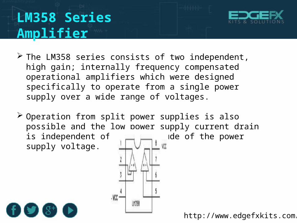
LM358 Series Amplifier The LM358 series consists of two independent, high gain; internally
frequency compensated operational amplifiers which were designed specifically to operate from a single power supply over a wide range of voltages.
Operation from split power supplies is also possible and the low power supply current drain is independent of the magnitude of the power supply voltage.

http://www.edgefxkits.com/
Features Of LM358 Available in 8-Bump micro SMD chip sized package.
Large dc voltage gain: 100 Db.
Wide power supply range:
• Single supply: 3V to 32V
• or dual supplies: ±1.5V to ±16V
Very low supply current drain (500 µA)-essentially independent of supply voltage.
http://www.edgefxkits.com/
Working Principle
The project uses zero voltage reference ,8 Opto isolators(MOC3021) are used for driving 8 SCR’s. Triggering pulses so generated by the MC as per the program written provides input condition to the Opto isolator that drive the respective SCR to get conducting for 20ms from 1st bridge and next 20ms from the 2nd bridge to get the output, total time period of one AC cycle of 40ms which is 25 Hz.
Thus F/2 is delivered to the load while switch 1 is closed. Similarly for F/3 the conduction takes place for 30ms in the 1st bridge and next 30ms from the next bridge, such that a total time period of 1 cycle comes to 60ms which in turn in F/3 while switch -2 is operated. Fundamental frequency of 50Hz is available by triggering on pair from the 1st bridge for 1st 10ms and for the next 10msfrom the next bridge while both the switches are kept in “OFF” condition. Reverse current flowing in the gates of the SCR’s are Opto – isolator output.

http://www.edgefxkits.com/
What is the Formula for Calculating Smoothing
Capacitor Value? There is some approximated formula .Peak to peak ripple voltage =
Load current in amps / (2*line frequency in hertz *capacitance in farads). But as rule of thumb for 1 A current 1000uF is best. Thus it is load dependent.